EP0000340B1 - Device for folding curtains ands screens - Google Patents
Device for folding curtains ands screens Download PDFInfo
- Publication number
- EP0000340B1 EP0000340B1 EP78100215A EP78100215A EP0000340B1 EP 0000340 B1 EP0000340 B1 EP 0000340B1 EP 78100215 A EP78100215 A EP 78100215A EP 78100215 A EP78100215 A EP 78100215A EP 0000340 B1 EP0000340 B1 EP 0000340B1
- Authority
- EP
- European Patent Office
- Prior art keywords
- pleat
- carrier plate
- clamp
- support plate
- curtain
- Prior art date
- Legal status (The legal status is an assumption and is not a legal conclusion. Google has not performed a legal analysis and makes no representation as to the accuracy of the status listed.)
- Expired
Links
- 239000004744 fabric Substances 0.000 description 14
- 210000000078 claw Anatomy 0.000 description 7
- 230000037431 insertion Effects 0.000 description 3
- 238000003780 insertion Methods 0.000 description 3
- 239000000463 material Substances 0.000 description 3
- 206010040954 Skin wrinkling Diseases 0.000 description 2
- 239000002585 base Substances 0.000 description 2
- 239000004033 plastic Substances 0.000 description 2
- 230000007704 transition Effects 0.000 description 2
- 238000005406 washing Methods 0.000 description 2
- 239000004952 Polyamide Substances 0.000 description 1
- 239000003513 alkali Substances 0.000 description 1
- 238000005452 bending Methods 0.000 description 1
- 230000015572 biosynthetic process Effects 0.000 description 1
- 238000004140 cleaning Methods 0.000 description 1
- 238000010276 construction Methods 0.000 description 1
- 229920002647 polyamide Polymers 0.000 description 1
- 239000000725 suspension Substances 0.000 description 1
- 229920001169 thermoplastic Polymers 0.000 description 1
- 239000004416 thermosoftening plastic Substances 0.000 description 1
- 230000037303 wrinkles Effects 0.000 description 1
Images


Classifications
-
- A—HUMAN NECESSITIES
- A47—FURNITURE; DOMESTIC ARTICLES OR APPLIANCES; COFFEE MILLS; SPICE MILLS; SUCTION CLEANERS IN GENERAL
- A47H—FURNISHINGS FOR WINDOWS OR DOORS
- A47H13/00—Fastening curtains on curtain rods or rails
- A47H13/14—Means for forming pleats
-
- Y—GENERAL TAGGING OF NEW TECHNOLOGICAL DEVELOPMENTS; GENERAL TAGGING OF CROSS-SECTIONAL TECHNOLOGIES SPANNING OVER SEVERAL SECTIONS OF THE IPC; TECHNICAL SUBJECTS COVERED BY FORMER USPC CROSS-REFERENCE ART COLLECTIONS [XRACs] AND DIGESTS
- Y10—TECHNICAL SUBJECTS COVERED BY FORMER USPC
- Y10T—TECHNICAL SUBJECTS COVERED BY FORMER US CLASSIFICATION
- Y10T24/00—Buckles, buttons, clasps, etc.
- Y10T24/34—Combined diverse multipart fasteners
- Y10T24/3427—Clasp
- Y10T24/3449—Clasp and hook
- Y10T24/3451—Clasp and hook having intermediate connector allowing movement
- Y10T24/3452—Clasp and hook having intermediate connector allowing movement and adjustment means
Definitions
- the invention relates to a device for fixing folds on curtains and curtains, with fold clamping devices in the form of vertically extending webs, wherein at least one inserted fold is held in an elastically clamping manner in a slot formed between two webs, and projecting on the webs into the respective slot barb-like projections are arranged.
- Such a device known from DE-PS 22 27 199 (corresponding to US-PS 3 861 001) is formed in one piece.
- This known device has the general advantage that it is relatively simple due to its one-piece construction.
- Their disadvantage is that the folds are only held on their feet.
- This known device is that the formation of a so-called head on the curtain, i. H. it is not possible to form a part on the curtain that goes upward beyond the holding device. Furthermore, this known device is not suitable for holding more sensitive curtain fabrics, since due to the punctiform mounting on the barbs of the claws, tearing of the fabric is to be feared when loaded. In addition, the front finger-like claws are visible when a forward protruding fold is formed, which is aesthetically disturbing.
- a holding device for curtains in which a hook can be fastened to a holding device by means of pins projecting from a plate of the hook with spherical heads, which in corresponding openings of the Holding body are insertable.
- the invention has for its object to provide a device of the type described above, by means of which the protruding folds are held securely and precisely in their shape without the folds in the fixing area becoming completely rigid.
- an elastically lockable pleat clip which carries at its front at least two formed by two webs, aligned, spaced-apart pleat clamps, at least one pleat clamp protrudes approximately as far as corresponds to the depth of the folds to be fixed, while the other fold clamping device protrudes by a significantly smaller distance, that the fold clamp can be locked at a distance from the support plate with this by means of centrally arranged locking devices and on both sides of these locking devices elastically deformable, with their outer longitudinal sides up close the wing has reaching wings and that the fold clip in the region of its longitudinal sides and the support plate have mutually associated tooth-like projections.
- This configuration according to the invention makes it possible, on the one hand, to hold folds to be fixed in the widely projecting fold clamping device, which extends only over a small area of the overall height of the device, in such a way that they are fixed over their full depth.
- the other fold clamping device on the other hand, only the foot is held by one or more folds, so that the folds can already spring open again without changing their position relative to the device.
- a double layer of fabric is firmly fixed between the fold clip and the trapeze, which means that the outer layer of the outer folds is also precisely fixed.
- the curtain or the curtain itself is carried by the device.
- the entire device is located on the back of the curtain and is therefore not recognizable from its visible side.
- the fold clip advantageously has an approximately cylindrical segment-shaped cross section.
- the locking devices by at least; a pair of elastic arms attached to the inside of the folding clamp with outwardly projecting projections with stop faces and in the support plate associated locking openings with contact surfaces are formed.
- a two-part, interlocking embodiment of a device for holding curtains is already known, in which wiping on both sides of the folds can be pinched.
- At least one pair of elastic arms with outwardly protruding projections with stop surfaces are provided as the locking device, which correspond to the associated locking openings in the other part, which also have contact surfaces for the stop surfaces.
- a hook which has at least one row with projecting pins which can be inserted into corresponding openings in the support plate.
- a device for hanging curtains and curtains to provide a row of pins on a runner to be guided in a curtain rail, which pins enter corresponding openings in one at the upper edge of the curtain or the curtain the clip to be attached can be inserted.
- the hook In order to ensure an absolutely safe but detachable hanging, the hook has a bracket attached to a plate, the free end of which can be connected to the plate in the manner of a safety pin.
- a safety pin-like hanger for curtains and drapes is known.
- the safety pin-like bunch is pulled through and closed directly by loops of a carrying strap attached to the upper edge of the curtain or the curtain.
- the hanger has sliders or rollers at its upper end.
- the device shown in the drawing consists of a support plate 1, on the front of which a folding clip 2 and on the rear of which a hook 3 can each be detachably attached.
- the support plate 1 has a flat, elongated, rectangular shape. On its front side 4 it is provided with tooth-like projections 5, of which a row is provided in the vicinity of the associated side edge 6 and 7, respectively. These rows of tooth-like projections 5 run parallel to one another and to the center line 8 of the support plate 1.
- the tooth-like projections 5 have the shape of a triangular pyramid, one side surface 9 of which faces away from the associated side edge 6 or 7 protrudes perpendicularly from the front side 4 of the support plate while the other two side surfaces 10, 11 run flat inclined towards the outer edge.
- a series of openings 12 are provided from each of these. These each consist of a cylindrical section 13 lying towards the front side 4 of the support plate 1, a cylindrical section 14 of smaller diameter adjoining it and located inside the support plate 1 and a frustoconical section 16 widening towards the rear side 15 of the support plate 1 Between the cylindrical section 13 and the cylindrical section 14 with a smaller diameter, an annular contact shoulder 17 directed towards the front side 4 is formed.
- each locking openings 18, likewise extending through the support plate 1 from its front side 4 to its rear side 15, of approximately rectangular cross section in plan view ⁇ . They consist of a narrowest rectangular section 19 lying in the interior of the support plate 1, on the vertical side surfaces 20 of which the insertion surfaces 21 adjoin one another at a distance from the front side 4. The side surfaces 20 of the section 19 spring back toward the rear 15, forming contact surfaces 22 that are open toward the rear 15, so that an enlarged section 23 is formed here.
- a hook 3 has a plate 24, from the top 25 of which a bracket 26 is attached bent backwards and downwards.
- the bracket 26 is provided with a tapered section 27 in the region of its free end.
- an upwardly open box 29 is attached to the latter, one side wall 30 of which is provided with a recess 31 in the region of the rear side 28 of the plate 24.
- Attached to the front 34 of the plate 24 are two rows of vertically projecting pins 35, each having a spherical head 36 at its end.
- the two rows of pins 35 with heads 36 are at the same distance a from one another that the two rows of openings 12 have in the support plate 1.
- the distance b between two adjacent pins 35 with heads 36 in a row is the same as the distance between two adjacent openings 12 in the support plate 1.
- the diameter of the pins 35 is slightly smaller than the diameter of the narrow cylindrical sections 14 in the support plate.
- the diameter of the spherical heads 36 is somewhat larger than the diameter of the narrower cylindrical sections 14 and somewhat smaller than the diameter of the further cylindrical sections 13.
- the heads 36 When a connection is made between the hook 3 and a support plate 1, the heads 36 become into the frustoconical sections 16 pressed in, causing the heads to deform slightly elastically so that they can be pushed through the narrower sections 14. In the other cylindrical sections 13, they spring back up again and lie behind the system shoulder 17, which creates a very firm but detachable connection between the hook 3 and the support plate 1. Since a relatively large number of openings 12 are provided on the support plate 1 in each row, the hook 3 can be attached to the support plate 1 in very different heights.
- the folding clip 2 has an elongated, elastically deformable clip part 37, approximately rectangular in plan view, which — in cross section — has approximately the shape of a ring cylinder segment.
- the fold clip 2 is constructed symmetrically to a plane of symmetry 38.
- On the inside 39 of the bent clamp part 37 are attached in pairs projecting elastic webs 40, 41 which have barbs 42, 43 projecting outwards in the region of their free ends. These barbs 42 and 43 have inclined surfaces 44 running away from the inside 39 and stop faces 45 facing the inside 39.
- the three pairs of webs 40, 41 are arranged at the same distance c from one another as the locking openings 18 in the support plate 1.
- the length of the webs 40, 41 is slightly less than the length of the locking openings 18.
- a series of tooth-like projections 49 is attached, which are identical to the projections 5.
- the distance d between the two rows of protrusions is the same as that of the support plate 1.
- the one protrusions 49 are only arranged in such a way that when the pleat clip 2 is locked with the support plate 1 they each pass between two adjacent protrusions 5 of the support plate 1.
- these projections 49 thus have side faces 50 that face each other and lie parallel to the plane of symmetry 38.
- the length of the webs 40, 41 on the one hand and the curvature of the clamp part 37 is selected such that when the fold clamp 2 is locked with the support plate 1, some air is still left between the respective tips of the projections 5 and 49 and the associated front side 4 of the support plate 1 and the longitudinal edges 47 48 of the folding clip 2.
- two fold clamping devices 52, 53 are attached at a distance from one another. These in turn consist of two spaced apart webs 54 and 55, which are provided in the region of their free ends with tooth-like projections 56, 57 directed towards each other.
- These vane-like projections 56, 57 have on their outer side inclined insertion surfaces 58, 59 towards the front side 51 of the clamp part and on their side facing the front side 51 approximately perpendicular to the plane of symmetry 38 side surfaces 60 and 61; also the tooth-like; Protrusions 56, 57 are thus designed like barbs.
- the webs of the fold clamping device 52 protrude much more from the front side 51 than the webs 55 of the fold clamping device 53.
- the middle fold foot 68 is pushed between the webs 55 of the smaller upper fold clamping device 53, where it is then likewise secured against being pulled out.
- the fabric of the curtain or of the curtain 62 folded over the long sides 47, 48 of the pleated clip 2, so that between these longitudinal edges 47, 48 and the webs 40, 41 there is a double layer of fabric 70, 71, then the pleated clip 2 in the manner already described with the support plate 1 locked, whereby the two double fabric layers 70, 71 each forming an outer fold base are firmly secured between the support plate and fold clamp against being pulled out.
- the support plate 1, the folding clip 2 and the hook 3 are each made in one piece from a hard elastic thermoplastic.
- the hook 3 can be attached to the support plate 1 at any height as described. Then the entire curtain or the curtain 62 is securely but releasably attached to a curtain rail according to the so-called American system by means of the hook.
- the support plate 1, folding clip 2 and the hook 3 are expediently made of alkali and light-stable plastic, such as. B. made of a polyamide.
- alkali and light-stable plastic such as. B. made of a polyamide.
- a knitted or woven stiffening band 77 is always processed at the same time when folding, which is shown in FIG the side areas is shown so as not to disturb the clarity of the drawing. It lies close to the back of the fabric, so it also extends along the folds 63 to 66 on the inside thereof.
- Such a stiffening band 77 will generally be so wide that it extends from the upper edge of the curtain to below the lower fold clamping device 52.
- a curtain can simply be a lining material attached to its rear. As a rule, such a stiffening tape will be sewn onto the curtain or the curtain 62.
Description
Die Erfindung betrifft eine Vorrichtung zur Fixierung von Falten an Gardinen und Vorhängen, mit Faltenklemmeinrichtungen in Form von vertikal verlaufenden Stegen, wobei in einem zwischen jeweils zwei Stegen gebildeten Schlitz mindestens eine eingeführte Falte elastisch klemmend _gehalten wird und wobei an den Stegen in den jeweiligen Schlitz hineinragende widerhakenartige Vorsprünge angeordnet sind.The invention relates to a device for fixing folds on curtains and curtains, with fold clamping devices in the form of vertically extending webs, wherein at least one inserted fold is held in an elastically clamping manner in a slot formed between two webs, and projecting on the webs into the respective slot barb-like projections are arranged.
Eine derartige aus der DE-PS 22 27 199 (entsprechend US-PS 3 861 001) bekannte Vorrichtung ist einstückig ausgebildet. Diese bekannte Vorrichtung weist den generellen Vorteil auf, daß sie aufgrund ihrer Einstückigkeit verhältnismäßig einfach aufgebaut ist. Ihr Nachteil besteht darin, daß die Falten nur an ihrem Fuß gehalten werden.Such a device known from DE-PS 22 27 199 (corresponding to US-
Aus der US-PS 3 223 148 ist eine Vorrichtung zur Fixierung von Falten an Gardinen und' Vorhängen bekannt, bei der die Falten an einem einstückigen, aus hartelastischem Kunststoff bestehenden Haltekörper gehalten werden, an dem ebenfalls von oben nach unten verlaufende Stege angeordnet sind, und wobei ebenfalls in dem zwischen zwei Stegen gebilde-. ten, oben und unten offenen Schlitz eine eingeführte Falte elastisch klemmend gehalten wird. Diese Schlitze sind an ihrem inneren geschlossenen Ende kreisförmig erweitert, so daß die Falten an ihrem Faltenfuß mittels eines Haltestabes von kreisförmigem Querschnitt gehalten werden können. Die als Hohlköper ausgebildeten Stege müssen so elastisch sein, daß die kreisförmigen Haltestäbe zusammen mit der doppelt liegenden Stofflage von vorm eingeschoben werden können. Dies hat aber wiederum zur Folge, daß mit dem gleichen Kraftaufwand, mit dem der Gardinenstoff samt Haltestab in den Schlitz eingedrückt wird, diese auch wieder herausgezogen werden kann. Des weiteren bedingt die verhältnismäßig große Breite des Schlitzes an seinem inneren geschlossenen Ende auch einen entsprechend großen Abstand einzelner benachbarter Schlitze, so daß der Haltekörper insgesamt verhältnismäßig groß und unförmig wird. Dies fuhrt wiederum dazu, daß mit einem derartigen Haltekörper keine eng zusammengefaßte Fältelung vorgenommen werden kann. Wegen der geringen Sicherheit der Faltenfixierung besteht auch die Gefahr, daß der Haltekörper: bei einem Waschen oder Reinigen der Gardine sich von dem Stoff löst.From US Pat. No. 3,223,148 a device for fixing folds to curtains and curtains is known, in which the folds are held on a one-piece holding body made of hard-elastic plastic, on which webs also running from top to bottom are arranged, and also formed in the between two webs. ten, open slot above and below an inserted fold is held elastically clamping. These slots are circularly widened at their inner closed end so that the folds can be held on their fold base by means of a holding rod of circular cross-section. The webs designed as a hollow body must be so elastic that the circular holding rods can be inserted from the front together with the double layer of fabric. However, this in turn means that it can be pulled out again with the same force with which the curtain fabric and the holding rod are pressed into the slot. Furthermore, the relatively large width of the slot at its inner closed end also requires a correspondingly large distance between individual adjacent slots, so that the holding body as a whole is relatively large and bulky. This in turn leads to the fact that such a holding body cannot be used to carry out a crimp that is tightly summarized. Because of the low security of the wrinkle fixation, there is also the danger that the holding body: detaches from the fabric when washing or cleaning the curtain.
Aus der US-PS 1 149 628 ist eine Einrichtung zur Fixierung von Falten an Vorhängen bekannt, mit der an einem in seinem Durchmesser verstellbaren, auf einer zylindrischen Gardinenstange zu führenden Haltering nach unten vorspringende Klauen vorgesehen sind. Auf der der Rückseite des Vorhands zugeordneten Seite ist eine einzige Klaue mit nach vorn vorspringenden Widerhaken vorgesehen, während an der der Vorderseite des Vorhangs zugewandten Seite zwei parallel zueinander verlaufende, fingerartige Klauen mit nach hinten vorspringenden Widerhaken vorgesehen sind. Mittels dieser Klauen wird der Vorhangstoff punktartig gehalten. Durch die beiden vorderen fingerartigen Klauen kann eine senkrecht zum Vorhand nach vorn vorspringende Falte herausgezogen werden. Des weiteren kann mit dieser bekannten Einrichtung nur eine einfache T-Falte gehalten werden. Der Nachteil diser bekannten Einrichtung liegt darin, daß die Bildung eines sogenannten Köpfchens am Vorhang, d. h. die Bildung eines über die Halteeinrichtung nach oben hinausgehenden Teils am Vorhang nicht möglich ist. Des weiteren ist diese bekannte Einrichtung nicht dazu geeignet, empfindlichere Gardinenstoffe zu halten, da aufgrund der punktförmigen Halterung an den Widerhaken der Klauen bei einer Belastung ein Zerreißen des Stoffes zu befürchtem ist. Außderdem sind bei der Bildung einer nach vorn vorspringenden Falte die vorderen fingerartigen Klauen sichtbar, was ästhetisch störend ist.From US-
Aus der DT-PS 22 55 328 (entsprechend US―PS 3 921 696) ist eine Haltevorrichtung für Gardinen bekannt, bei der an einer Halteeinrichtung ein Haken mittels von einer Platte des Hakens vorspringenden Zapfen mit kugelförmigen Köpfen befestigbar ist, die in entsprechende Öffnungen des Haltekörpers einführbar sind.From DT-
Der Erfindung liegt die Aufgabe zugrunde, eine Vorrichtung der eingangs beschriebenen Art zu schaffen, mittels der nach vom vorspringende Falten sicher und un ihrer Form genau fixiert gehalten werden, ohne daß die Falten im Fixierungsbereich in sich völlig starr werden.The invention has for its object to provide a device of the type described above, by means of which the protruding folds are held securely and precisely in their shape without the folds in the fixing area becoming completely rigid.
Diese Aufgabe wird erfindungsgemäß dadurch gelöst, daß eine elastisch mit einer Tragplatte verriegelbare Faltenklammer vorgesehen ist, die an ihrer Vorderseite mindestens zwei durch je zwei Stege gebildete, miteinander fluchtende, im Abstand voneinander angebrachte Faltenklemmeinrichtungen trägt, wobei mindestens eine Faltenklemmeinrichtung etwa so weit vorspringt, wie der Tiefe der zu fixierenden Falten entspricht, während die andere Faltenklemmeinrichtung um einen deutlich kleineren Abstand vorspringt, daß die Faltenklammer im Abstand von der Tragplatte mit dieser mittels mittig angeordneter Veriegelungseinrichtungen verriegelbar ist und beiderseits dieser Verriegelungseinrichtungen elastisch verformbare, mit ihren äußeren Längsseiten bis in die Nähe der Tragplatte reichende Flügel aufweist und daß die Faltenklammer im Bereich ihrer Längsseiten und die Tragplatte einander zugeordnete zahnartige Vorsprünge aufweisen.This object is achieved in that an elastically lockable pleat clip is provided which carries at its front at least two formed by two webs, aligned, spaced-apart pleat clamps, at least one pleat clamp protrudes approximately as far as corresponds to the depth of the folds to be fixed, while the other fold clamping device protrudes by a significantly smaller distance, that the fold clamp can be locked at a distance from the support plate with this by means of centrally arranged locking devices and on both sides of these locking devices elastically deformable, with their outer longitudinal sides up close the wing has reaching wings and that the fold clip in the region of its longitudinal sides and the support plate have mutually associated tooth-like projections.
Durch diese erfindungsgemäße Ausgestaltung ist es möglich, zu fixierende Falten einerseits in der weit vorpringenden Faltenklemmeinrichtung, die sich nur über einen kleinen Bereich der Gesamthöhe der Vorrichtung erstreckt, so zu halten, daß sie über ihre volle Tiefe fixiert werden. In der anderen Faltenklemmeinrichtung wird dagegen nur der Fuß von einer oder mehreren Falten gehalten, so daß die Falten hier bereits wieder aufspringen können, ohne daß sie ihre Lage relativ zu der Vorrichtung verändern. Am Übergang von dem nicht gefalteten Bereich der Gardine bzw. des Vorhangs zu den Falten wird jeweils eine doppelte Stofflage zwischen der Faltenklammer und der Traplatte fest fixiert, wodurch gleichzeitig auch die jeweils äußere Stofflage der außenliegenden Falten genau fixiert wird. Hier wird auch die Gardine bzw. der Vorhang selbst von der Vorrichtung getragen. Je dicker, d. h. je shwerer der Stoff der Gardine bzw. des Vorhangs ist, umso weiter werden die Flügel der Faltenklammer elastisch aufgeweitet, umso stärker ist die Klemmkraft zwischen der Faltenklammer und der Tragplatte. Aufgrund der erfindungsgemäßen Ausgestaltung liegt die gesamte Vorrichtung auf der Rückseite der Gardine, ist von ihrer Sichtseite her also nicht erkennbar.This configuration according to the invention makes it possible, on the one hand, to hold folds to be fixed in the widely projecting fold clamping device, which extends only over a small area of the overall height of the device, in such a way that they are fixed over their full depth. In the other fold clamping device, on the other hand, only the foot is held by one or more folds, so that the folds can already spring open again without changing their position relative to the device. At the transition from the non-folded area of the curtain or the curtain to the folds, a double layer of fabric is firmly fixed between the fold clip and the trapeze, which means that the outer layer of the outer folds is also precisely fixed. Here, the curtain or the curtain itself is carried by the device. The thicker, H. the heavier the fabric of the curtain or the curtain, the further the wings of the pleated clip are elastically expanded, the stronger the clamping force between the pleated clip and the support plate. Because of the configuration according to the invention, the entire device is located on the back of the curtain and is therefore not recognizable from its visible side.
Vorteilhafterweise weist die Faltenklammer einen etwa zylindersegmentförmigen Querschnitt auf. Nach einer besonders vorteilhaften Ausgestaltung ist vorgesehen, daß die Verriegelungseinrichtungen durch mindestens; ein Paar an der Innenseite der Faltenklammer angebrachte elastische Arme mit nach außen ragenden Vorsprüngen mit Anschlagflächen und in der Tragplatte diesen zugeordnete Verriegelungsöffnungen mit Anlageflächen gebildet sind. Aus der DE-OS 25 50 786 ist zwar bereits eine zweiteilige, miteinander verriegelbare Ausführung einer Vorrichtung zum Halten von Gardinen bekannt, bei welcher beidseitig wischen beiden Teilen Falten eingeklemmt werden können. Als Verriegelungseinrichtung sind hier mindestens ein Paar elastischer Arme mit nach außen ragenden Vorsprüngen mit Anschlagflächen vorgesehen, denen in dem anderen Teil zugeordnete Verriegelungsöffnungen entsprechen, die auch Anlageflächen für die Anschlagflächen aufweisen.The fold clip advantageously has an approximately cylindrical segment-shaped cross section. According to a particularly advantageous embodiment, it is provided that the locking devices by at least; a pair of elastic arms attached to the inside of the folding clamp with outwardly projecting projections with stop faces and in the support plate associated locking openings with contact surfaces are formed. From DE-OS 25 50 786 a two-part, interlocking embodiment of a device for holding curtains is already known, in which wiping on both sides of the folds can be pinched. At least one pair of elastic arms with outwardly protruding projections with stop surfaces are provided as the locking device, which correspond to the associated locking openings in the other part, which also have contact surfaces for the stop surfaces.
Weiterhin ist es insbesondere für das sogenannte amerikanische Aufhängesystem von Vorteil, wenn ein Haken vorgesehen ist, der mindestens eine Reihe mit vorspringenden Zapfen aufweist, die in entsprechende Öffnungen in der Tragplatte einführbar sind. Hierzu ist es aus der US-PS 3 992 749 bei einer Vorrichtung zum Aufhängen von Gardinen und Vorhängen bekannt, an einem in einer Gardinenschiene zu führenden Läufer eine Reihe von Zapfen vorzusehen, die in entsprechende Öffnungen einer am oberen Rand der Gardine bzw. des Vorhangs anzubringenden Klammer einführbar sind.Furthermore, it is particularly advantageous for the so-called American suspension system if a hook is provided which has at least one row with projecting pins which can be inserted into corresponding openings in the support plate. For this purpose, it is known from US Pat. No. 3,992,749 for a device for hanging curtains and curtains to provide a row of pins on a runner to be guided in a curtain rail, which pins enter corresponding openings in one at the upper edge of the curtain or the curtain the clip to be attached can be inserted.
Um ein absolut sicheres aber lösbares Aufhängen zu gewahrleisten, weist der Haken einen an einer Platte angebrachten Bügel auf, dessen freies Ende nach Art einer Sicherheitsnadel mit der Platte verbindbar ist. Aus der DE―OS 20 65 908 ist ein sicherheitsnadelartiger Aufhänger für Gardinen und Vorhänge bekannt. Der sicherheitsnadelartige Büngel wird hierbei direkt durch Schlaufen eines am oberen Rand der Gardine bzw. des Vorhangs angebrachten Tragebandes hindurchgezogen und verschlossen. Der Aufhänger weist an seinem oberen Ende Gleiter oder Rollen auf.In order to ensure an absolutely safe but detachable hanging, the hook has a bracket attached to a plate, the free end of which can be connected to the plate in the manner of a safety pin. From DE ― OS 20 65 908 a safety pin-like hanger for curtains and drapes is known. The safety pin-like bunch is pulled through and closed directly by loops of a carrying strap attached to the upper edge of the curtain or the curtain. The hanger has sliders or rollers at its upper end.
Weitere Vorteile und Merkmale der Erfindung ergeben sich aus der Beschreibung eines Ausführungsbeispiels anhand der Zeichnung. In der Zeichnung zeigt.
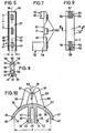
- Fig. 1 eine Tragplatte einer erfindungsgemäßen Vorrichtung in Draufsicht,
- Fig. 2 einen Querschnitt durch Fig. 1 gemäß der Schnittlinie II-II in gegenüber Fig. 1 vergrößertem Maßstab,
- Fig. 3 einen Haken einer erfindungsgemäßen Vorrichtung in Seitenansicht,
- Fig. 4 den Haken nach Fig. 3 in Draufsicht,
- Fig. 5 einen Querschnitt durch den Haken gemäß der Schnittlinie V-V in Fig. 3,
- Fig 6 eine Faltenklammer der erfindungsgemäßen Vorrichtung einer Rückansicht,
- Fig. 7 eine Seitenansicht der Faltenklammer,
- Fig. 8 eine Unteransicht der Faltenklammer
- Fig. 9 eine Draufsicht auf die Faltenklammer,
- Fig. 10 einen Teil-Querschnitt durch die Faltenklamnier in gegenüber Fig. 6 bis 9 vergrößertem Maßstab,
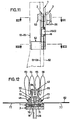
- Fig. 11 eine Seitenansicht einer zusammengebauten Vorrichtung mit eingelegten Falten,
- Fig. 12 einen Querschnitt durch Fig. 11 gemäß der Schnittlinie XII-XII in Fig. 11 und
- Fig. 13 einen Querschnitt durch Fig. 11 gemäß der Schnittlinie XIII-XIII.
- 1 is a top view of a support plate of a device according to the invention,
- 2 shows a cross section through FIG. 1 along the section line II-II on an enlarged scale compared to FIG. 1,
- 3 is a side view of a hook of a device according to the invention,
- 4 is a top view of the hook according to FIG. 3,
- 5 shows a cross section through the hook along the section line VV in FIG. 3,
- 6 shows a folding clip of the device according to the invention from a rear view,
- 7 is a side view of the pleat clip,
- Fig. 8 is a bottom view of the pleat clip
- 9 is a plan view of the pleat clip,
- 10 is a partial cross section through the pleated clip on an enlarged scale compared to FIGS. 6 to 9,
- 11 is a side view of an assembled device with inserted folds,
- Fig. 12 is a cross section through Fig. 11 along the section line XII-XII in Fig. 11 and
- Fig. 13 is a cross section through Fig. 11 along the section line XIII-XIII.
Die in der Zeichnung dargestellte Vorrichtung besteht aus einer Tragplatte 1, an deren Vorderseite eine Faltenklammer 2 und an deren Rückseite ein Haken 3 jeweils lösbar befestigt werden können.The device shown in the drawing consists of a
Die Tragplatte 1 weist eine flache, längliche, rechteckige Form auf. Auf ihrer Vorderseite 4 ist sie mit zahnartigen Vorsprüngen 5 versehen, von denen jeweils eine Reihe in der Nähe des zugehörigen Seitenrandes 6 bzw. 7 vorgesehen ist. Diese Reihen von zahnartigen Vorsprüngen 5 verlaufen parallel zueinander und zur Mittellinie 8 der Tragplatte 1. Die zahnartigen Vorsprünge 5 haben die Form einer Dreieck-Pyramide, deren eine, dem zugehörigen Seitenrand 6 bzw. 7 abgewandte Seitenfläche 9 senkrecht von der Vorderseite 4 der Tragplatte hochragt während die beiden anderen Seitenflächen 10, 11 flach geneigt zum Außenrand hin verlaufen.The
Innerhalb der beiden Reihen von zahnartigen Vorsprüngen 5 sind wiederum parallel zur Mittellinie 8 und beiderseits im gleichen Abstand von dieser jeweils eine Reihe von Öffnungen 12 vorgesehen. Diese bestehen jeweils aus einem zur Vorderseite 4 der Tragplatte 1 hin liegenden zylindrischen Abschnitt 13 einem sich an diesen anschließenden, im Inneren der Tragplatte 1 befindlichen zylindrischen Abschnitt 14 kleineren Durchmessers und einem sich zur Rüchseite 15 der Tragplatte 1 hin erweiternden kegelstumpfförmigen Abschnitt 16. Am Übergang zwischen dem zylindrischen Abschnitt 13 und dem zylindrischen Abschnitt 14 mit kleinerem Durchmesser ist eine ringförmige zur Vorderseite 4 hin gerichtete Anlageschulter 17 ausgebildet.Within the two rows of tooth-
Längs der Mittellinie 8 sind drei sich ebenfalls durch die Tragplatte 1 von deren Vorderseite 4 bis zu ihrer Rückseite 15 erstreckende Verriegelungsöffnungen 18 von-in der Draufsicht―etwa rechteckigem Querschnitt angebracht. Sie bestehen aus einem im Inneren der Tragplatte 1 liegenden engsten rechteckigen Abschnitt 19, an dessen vertikale Seitenflächen 20 sich zur Vorderseite 4 hin im Abstand voneinander erweiternde Einführflächen 21 anschließen. Zur Rückseite 15 hin springen die Seitenflächen 20 des Abschnitts 19 unter Bildung von zur Rückseite 15 hin offenen Anlageflächen 22 zurück, so daß sich hier ein erweiterter Abschnitt 23 bildet.Along the center line 8 there are three locking
Ein Haken 3 weist eine Platte 24 auf, von deren Oberseite 25 ein nach hinten und unten abgebogener Bügel 26 angebracht ist. Der Bügel 26 ist im Bereich seines freien Endes mit einem verjüngten Abschnitt 27 versehen. Im unteren Bereich der dem Bügel 26 zugewandten Rückseite 28 der Platte 24 ist an dieser ein nach oben offener Kasten 29 angebracht, dessen eine Seitenwand 30 im Bereich der Rückseite 28 der Platte 24 mit einer Ausnehmung 31 versehen ist. Durch Verbiegen des Bügels 26 zur Rückseite 28 der Platte 24 hin unter gleichzeitiger leichter seitlicher Verformung kann der Verjüngte Abschnitt 27 des Bügels 26 an der die Ausnehmung 31 aufweisenden Seitenwand vorbeigeführt und der verjüngte Abschnitt 27 durch die Ausnehmung 31 in das Innere des Kastens 29 eingeführt werden. Aufgrund der elastischen Aufdehnung des Bügels 26 bei Entlastung legt sich der verjüngte Abschnitt 27 gegen die Rückwand 32 des Kastens und ist seitlich zwischen der Seitenwand 30 und der gegenüberliegenden Seitenwand 33 festgelegt. Der Haken 3 kann also nach Art einer Sicherheitsnadel geschlossen werden.A
An der Vorderseite 34 der Platte 24 sind zwei Reihen von senkrecht vorspringenden Zapfen 35 angebracht, die jeweils einen kugelförmigen Kopf 36 an ihrem Ende aufweisen. Die beiden Reihen von Zapfen 35 mit Köpfen 36 weisen den gleichen Abstand a voneinander auf, den auch die beiden Reihen von Öffnungen 12 in der Tragplatte 1 aufweisen. Der Abstand b zweier benachbarter Zapfen 35 mit Köpfen 36 in einer Reihe ist der gleiche wie der Abstand zweier benachbarter Öffnungen 12 in der Tragplatte 1. Der Durchmesser der Zapfen 35 ist geringfügig kleiner als der Durchmesser der engen zylindrischen Abschnitte 14 in der Tragplatte. Der Durchmesser der kugelförmigen Köpfe 36 ist dagegen etwas größer als der Durchmesser der engeren zylindrischen Abschnitte 14 und etwas kleiner als der Durchmesser der weiteren zylindrischen Abschnitte 13. Beim Herstellen einer Verbindung zwischen dem Haken 3 und einer Tragplatte 1 werden die Köpfe 36 in die kegelstumpfförmigen Abschnitte 16 eingedrückt, wodurch sich die Köpfe leicht elastisch verformen, so daß sie durch die engeren Abschnitte 14 hindurchgedrückt werden können. In den weiteren zylindrischen Abschnitten 13 springen sie wieder elastisch auf und legen sich hinter die Anlageschultem 17, wodurch eine sehr feste aber mit größtem Kraftaufwand doch noch lösbare Verbindung dem Haken 3 und der Tragplatte 1 hergestellt wird. Da auf der Tragplatte 1 in jeder Reihe verhältnismäßig viele Offnungen 12 angebracht sind, kann der Haken 3 in sehr unterschiedlichen Höben an der Tragplatte 1 angebracht werden.Attached to the
Die Faltenklammer 2 weist ein längliches, in der Draufsicht etwa rechteckiges, elastisch verformbares Klammerteil 37 auf, das-im Querschnitt-etwa die Form eines Ringzylindersegmentes aufweist. Die Faltenklammer 2 ist symmetrisch zu einer Symmetrieebene 38 aufgebaut. An der Innenseite 39 des gebogenen Klammerteils 37 sind jeweils paarweise vorspringende elastische Stege 40, 41 angebracht, die im Bereich ihrer freien Enden nach außen vorstehende Widerhaken 42, 43 aufweisen. Diese Widerhaken 42 bzw. 43 weisen von der Innenseite 39 weg zueinander hin verlaufende Schrägflächen 44 und der Innenseiten 39 zugewandte anschlagflachen 45 auf. Die drei Paare von Stegen 40, 41 sind im selben Abstand c zueinander angebracht, wie die Verriegelungsöffnungen 18 in der Tragplatte 1. Die Länge der Stege 40, 41 ist etwas kleiner als die Länge der Verriegelungsöffnungen 18. Wenn die Faltenklammer 2 mit der Tragplatte 1 verriegelt werden soll, werden diese beiden Teile derart gegeneinander gedrückt, daß die Schrägflächen 44gegen die Einführflächen 21 der Tragplatte 1 anliegen. Bei einer gegeneinander gerichteten Kraft werden hierdurch die Stege unter Ausnutzung des zwischen ihnen befindlichen freien Raumes 46 elastisch gegeneinander, also zur Symmetrieebene 38 hin bewegt. Nachdem die Widerhaken 42, 43 durch den engsten Abschnitt 19 in der Tragplatte hindurchgeschoben worden sind, federn die Stege wieder auf, so daß sich die Anschlagflächen 45 der Widerhaken 42, 43 gegen die Anlageflächen 22 legen. Hiermit sind die Faltenklammer 2 und die Tragplatte 1 fest miteinander verriegelt. Ein Lösen dieser Verriegelung ist nur in der Weiss möglich, daß die Stege wieder zusammengebogen werden, so daß die Widerhaken durch den engen Abschnitt 19 herausgezogen werden können.The
An den beiden Längsseiten 47, 48 des Klammerteils 37 ist jeweils eine Reihe von zahnartigen Vorsprüngen 49 angebracht, die identisch wie die Vorsprünge 5 ausgebildet sind. Der Abstand d der beiden Reihen von Vorsprüngen ist der gleiche wie bei der Tragplatte 1. Die einseInen Vorsprünge 49 sind lediglich so angeordnet, daß sie beim Verriegeln der Faltenklammer 2 mit der Tragplatte 1 jeweils zwischen zwei benachbarten Vorsprüngen 5 der Tragplatte 1 gelangen. Insbesondere weisen diese Vorsprünge 49 also einander sugewandte parallel zu der Symmetrieebene 38 liegende Seitenflächen 50 auf.On the two
Die Länge der Stege 40, 41 einerseits und die Krümmung des Klammerteils 37 ist derart gewählt, daß bei Verriegelung der Faltenklammer 2 mit der Tragplatte 1 noch etwas Luft zwischen den jeweiligen Spitzen der Vorsprünge 5 bzw. 49 und der zugeordneten Vorderseite 4 der Tragplatte 1 bzw. den Längsrändern 47 48 der Faltenklammer 2 ist.The length of the
An der Vorderseite 51 des Klammerteils 37 sind im Abstand voneinander zwei Faltenklemmeinrichtungen 52, 53 angebracht. Diese bestehen wiederum aus jeweils zwei im Abstand voneinander angebrachten Stegen 54 bzw. 55, die im Bereich ihrer freien Enden mit aufeinanderzu gerichteten zahnartigen Vorsprüngen 56, 57 versehen sind.On the
Diese vahnartigen Vorsprünge 56, 57 weisen auf ihrer Außenseite zur Vorderseite 51 des Klammerteils hin geneigte Einschubflächen 58, 59 auf und an ihrer zur Vorderseite 51 hin gelegenen Seite etwa senkrecht zur Symmetrieebene 38 verlaufende Seitenflächen 60 bzw. 61 auf; auch die zahnartigen; Vorsprünge 56, 57 sind also widerhakenartig ausgebildet. Die Stege der Faltenklemmeinrichtung 52 ragen sehr viel stärker von der Vorderseite 51 vor als die Stege 55 der Faltenklemmeinrichtung 53.These vane-
Wenn am oberen Rand einer Garine oder eines Vorhangs 62 vier nach vorn vorstehende Falten 63, 64, 65, 66 gebildet und fixiert werden sollen, dann verden diese Falten unter entsprechender Raffung des Stoffes gebildet und die drei zwischen den beiden mittleren Falten 64, 65 und am Übergang zu den beiden äußeren Falten 63, 66 befindlichen Faltenfüße 67, 68, 69 unter entsprechender Aufweitung der Faltenklemmeinrichtung 52 zwischen deren Stege 54 bis auf die zwischen den Stegen 54 befindliche Vorderseite 51 der Faltenklammer 2 geschoben.If four forward protruding folds 63, 64, 65, 66 are to be formed and fixed at the upper edge of a curtain or
Nach Entlasten der Stege 54 legen sich diese wieder elastisch gegeneinander und halten den Stoff fest mit den zahnartigen Vorsprüngen 56, so daß dieser nicht wieder herausgezogen werden kann, ohne daß die Stege 54 auseinandergebogen werden.After relieving the
Gleichzeitig oder anschließend wird der mittlere Faltenfuß 68 zwischen die Stege 55 der kleineren oberen Faltenklemmeinrichtung 53 geschoben, wo er dann gleichermaßen gegen ein Herausziehen gesichert ist. Anschließend wird der Stoff der Gardine Bzw. des Vorhangs 62 über die Längsseiten 47, 48 der Faltenklammer 2 gefaltet, so daß zwischen diesen Längsrändern 47, 48 und den Stegen 40, 41 jeweils eine doppelte Stofflage 70, 71 liegt, Anschließend wird die Faltenklammer 2 in der beriets beschriebenen Weise mit der Tragplatte 1 verriegelt, wobei auch die beiden jeweils einen äußeren Faltenfuß bildenden doppelten Stofflagen 70, 71 fest zwischen Tragplatte und Faltenklanner gegen ein Herausziehen gesichert werden.Simultaneously or subsequently, the
Je dicker, d. h. je schwerer der Stoff der Gardine bzw. des Vorhangs 62 ist, desto größer sind die Verriegelungskräfte in den Faltenklemmeinrichtungen 52, 53 und zwischen dem Klammerteil 37 der Faltenklammer 2 und der Tragplatte 1, da die Stege 54 und 55 und die elastischen Flügel 72, 73 des Klammerteils 37 in Abhängigkeit von der Dicke des Stoffes elastisch verformt werden.The thicker, H. the heavier the fabric of the curtain or the
Die Tragplatte 1, die Faltenklammer 2 und der Haken 3 sind jeweils einstückig aus einem hartelastischen thermoplastischen Kunststoff hergestellt.The
Der Haken 3 kann in beliebiger Höhe-wie ;geschildertan der tragpiatte 1 angebracht werden. Anschließend wird die gesamte Gardine oder der Vorhang 62 mittels des Hakens sicher aber lösbar an einer Gardinenschiene nach dem sogenannten amerikanischen System befestigt.The
Am oberen Ende der Tragplatte sind an Wangen 74 miteinander fluchtende und aufeinanderzu gerichtete Zapfen 75, 76 vorgesehen, mittels derer eine Befestigung an Roll- oder Gleitaufhängern möglich ist, wie es im einzelnen in den DT―OSen 24 53 460 und 25 42 963 ausführlich dargestellt und beschrieben ist. Weiterhin ist es durch diese Ausgestaltung möglich, fertig konfektionierte Gardinen bzw. Vorhänge, die also fest mit einer Vorrichtung gemäß der Erfindung versehen sind, zum Auf- oder Abhängen und/oder zum Waschen in eine Vorrichtung einzuhängen, wie sie in der DT-OS 25 53 834 (entsprechend US-Serial No. 745 984) bekannt ist.At the upper end of the
Die Tragplatte 1, Faltenklammer 2 und der Haken 3 sind zweckmäßigerweise aus laugen-und lichtstabilem Kunststoff, wie z. B. einem Polyamid hergestellt. Wie sich aus der Zeichnung ergibt, ist die Vorrichtung lang im, Verhältnis zu ihrer Breite, so daß sich alle Faltenfüße verhältnismäßig dicht zusammenfassen lassen, andererseits aber eine aureichende Fixier- und Haltelänge zur Verfüngung steht.The
Um den Falten 63 bis 66 der Gardine bzw. des Vorhangs 62 einen guten Stand zu geben, d. h. um diese Falten ausreichend formstabil zu machen, wird beim Faltenlegen immer gleichzeitig ein gewirktes oder gewebtes Versteifungsband 77 verarbeitet, das in Fig. 12 nur in den seitlichen Bereichen dargestellt ist, um die Übersichtlichkeit der Zeichnung nicht zu stören. Es liegt dicht an der Rückseite des Stoffes an, erstreckt sich also auch längs der Falten 63 bis 66 jeweils an deren Innenseite. Ein solches Versteifungsband 77 wird in der Regel so breit sein, daß es sich vom oberen Rand der Gardine bis unterhalb der unteren Faltenklemmeinrichtung 52 erstreckt. Es kann sich hierbei aber auch insbesondere bei einem Vorhang einfach um einen an dessen Rückseite angebrachten Futterstoff handeln. In der Regel wird ein solches Versteifungsband an der Gardine bzw. dem Vorhang 62 angenäht sein.In order to give the
Claims (5)
Applications Claiming Priority (2)
| Application Number | Priority Date | Filing Date | Title |
|---|---|---|---|
| DE2732242 | 1977-07-16 | ||
| DE2732242A DE2732242C2 (en) | 1977-07-16 | 1977-07-16 | Device for fixing folds on curtains and drapes |
Publications (2)
| Publication Number | Publication Date |
|---|---|
| EP0000340A1 EP0000340A1 (en) | 1979-01-24 |
| EP0000340B1 true EP0000340B1 (en) | 1980-07-23 |
Family
ID=6014106
Family Applications (1)
| Application Number | Title | Priority Date | Filing Date |
|---|---|---|---|
| EP78100215A Expired EP0000340B1 (en) | 1977-07-16 | 1978-06-22 | Device for folding curtains ands screens |
Country Status (6)
| Country | Link |
|---|---|
| US (1) | US4166308A (en) |
| EP (1) | EP0000340B1 (en) |
| AT (1) | AT367627B (en) |
| DE (1) | DE2732242C2 (en) |
| DK (1) | DK281878A (en) |
| NO (1) | NO782287L (en) |
Families Citing this family (6)
| Publication number | Priority date | Publication date | Assignee | Title |
|---|---|---|---|---|
| US4277865A (en) * | 1978-06-14 | 1981-07-14 | Ietsugu Takazawa | Curtain hanger |
| US4344210A (en) * | 1979-09-10 | 1982-08-17 | Ryan Richard B | Adjustable drapery support assembly |
| US4261080A (en) * | 1979-09-10 | 1981-04-14 | Ryan Richard B | Adjustable drapery support assembly |
| US20100125987A1 (en) * | 2008-11-27 | 2010-05-27 | Ted Barkun | Curtain carrier for draping a curtain from a curtain rod |
| JP3161739U (en) * | 2010-05-28 | 2010-08-05 | 株式会社東京ソーイングカーテン | Curtain hanger |
| US10398248B1 (en) * | 2016-08-11 | 2019-09-03 | Ivan Curtis Burch, Jr. | Adjustable drapery form structure |
Family Cites Families (15)
| Publication number | Priority date | Publication date | Assignee | Title |
|---|---|---|---|---|
| BE530471A (en) * | ||||
| US2552922A (en) * | 1948-09-27 | 1951-05-15 | Rubie E Andreou | Pleater hook for drapes |
| US2765844A (en) * | 1955-12-09 | 1956-10-09 | Virginia R Kuddes | Apparatus for hanging draperies |
| FR1203911A (en) * | 1958-07-29 | 1960-01-21 | Clip for obtaining pleats on curtains and drapes and how to use it | |
| BE651540A (en) * | 1963-09-04 | 1964-12-01 | ||
| US3399712A (en) * | 1966-03-10 | 1968-09-03 | Worthy Products Corp | Drapery pleat forming and supporting assembly |
| FI47719C (en) * | 1967-12-30 | 1974-03-11 | Hachtel | Curtain picking device. |
| CH491634A (en) * | 1968-12-09 | 1970-06-15 | Concept S A | Device for hanging double curtains |
| US3735795A (en) * | 1970-11-12 | 1973-05-29 | Plastofold Ag | Support for suspending a curtain |
| AT321489B (en) * | 1972-06-03 | 1975-04-10 | Gardisette Holding | Device for fixing folds on curtains and drapes |
| US3921696A (en) * | 1972-11-11 | 1975-11-25 | Gardisette Holding | Fittings for gathering and fixing curtains or drapes |
| US3901303A (en) * | 1974-04-25 | 1975-08-26 | Douglas Manufacturing Co Inc | Drapery holder |
| CH567394A5 (en) * | 1974-08-15 | 1975-10-15 | Maron & Co Ag | |
| US3992749A (en) * | 1975-07-21 | 1976-11-23 | Getchell F Grant | Drapery slide and adjustable clip combination |
| DE2550786C3 (en) * | 1975-11-12 | 1978-05-24 | Gardisette Holding Ag, Luzern (Schweiz) | Curtain or curtain with double folds arranged and fixed on the upper edge |
-
1977
- 1977-07-16 DE DE2732242A patent/DE2732242C2/en not_active Expired
- 1977-10-17 US US05/843,042 patent/US4166308A/en not_active Expired - Lifetime
-
1978
- 1978-06-22 DK DK782818A patent/DK281878A/en not_active Application Discontinuation
- 1978-06-22 EP EP78100215A patent/EP0000340B1/en not_active Expired
- 1978-06-26 AT AT0461178A patent/AT367627B/en not_active IP Right Cessation
- 1978-06-30 NO NO782287A patent/NO782287L/en unknown
Also Published As
| Publication number | Publication date |
|---|---|
| ATA461178A (en) | 1981-12-15 |
| DK281878A (en) | 1979-01-17 |
| DE2732242B1 (en) | 1979-01-11 |
| NO782287L (en) | 1979-01-17 |
| AT367627B (en) | 1982-07-26 |
| DE2732242C2 (en) | 1979-08-30 |
| EP0000340A1 (en) | 1979-01-24 |
| US4166308A (en) | 1979-09-04 |
Similar Documents
| Publication | Publication Date | Title |
|---|---|---|
| DE3915461C2 (en) | Curtain glider | |
| EP0110811B1 (en) | Curtain heading tape | |
| DE1921295B2 (en) | Suspension device for curtains | |
| EP0000340B1 (en) | Device for folding curtains ands screens | |
| DE2139863C3 (en) | Kit for the production of completely or partially enclosed texts | |
| DE1268798B (en) | Hanging device for curtains | |
| CH702648A2 (en) | Curtain glider i.e. rotary glider, has gliding element including two-part gliding head upper part inserted into curtain rail section, and fastening element e.g. hook, for curtain attached at gliding element | |
| DE3004040C2 (en) | Hanger for drying clothes | |
| DE2107224C3 (en) | Inner curtain glider made of thermoplastic material | |
| DE2850036A1 (en) | FOLDING DRAPE HOOKS FOR CURTAINS | |
| DE3038022C2 (en) | Suspendable grid ceiling | |
| DE2227199C2 (en) | Device for fixing folds on curtains and drapes | |
| DE3512383C2 (en) | ||
| DE2255328C2 (en) | Device for gathering and fixing curtain material to be hung up | |
| DE2258213C3 (en) | Fixing clamp for strips with T-shaped recess for attachment to walls with through holes | |
| DE2328291C3 (en) | Device for holding curtains and drapes | |
| DE2240793C3 (en) | Device for hanging and gathering an open and close curtain made of flexible material | |
| DE2550786A1 (en) | Concealed double pleating fastener for curtains - comprises two interfitting plates for locking and holding curtain folds | |
| DE2227199B1 (en) | DEVICE FOR FIXING FOLDINGS ON CURTAINS AND CURTAINS | |
| DE2050237A1 (en) | Device to hang a folded curtain | |
| DE866993C (en) | File registration facility | |
| DE2328291B2 (en) | EQUIPMENT FOR HOLDING CURTAINS AND CURTAINS | |
| DE2453460B1 (en) | Easily detachable curtain runner arrangement - comprises curtain hooks fitting into runners and tracks at any point for pleated headings | |
| DE2534573A1 (en) | Curtain suspension hook and roller - hook forms pleats separated from roller for rehanging without removal from track | |
| DE3543314A1 (en) | GATHERED CURTAIN LIKE A CLOUD STORE |
Legal Events
| Date | Code | Title | Description |
|---|---|---|---|
| PUAI | Public reference made under article 153(3) epc to a published international application that has entered the european phase |
Free format text: ORIGINAL CODE: 0009012 |
|
| AK | Designated contracting states |
Designated state(s): BE CH FR GB NL SE |
|
| 17P | Request for examination filed | ||
| GRAA | (expected) grant |
Free format text: ORIGINAL CODE: 0009210 |
|
| AK | Designated contracting states |
Designated state(s): BE CH FR GB NL SE |
|
| PGFP | Annual fee paid to national office [announced via postgrant information from national office to epo] |
Ref country code: SE Payment date: 19810531 Year of fee payment: 4 |
|
| PGFP | Annual fee paid to national office [announced via postgrant information from national office to epo] |
Ref country code: NL Payment date: 19810630 Year of fee payment: 4 Ref country code: CH Payment date: 19810630 Year of fee payment: 4 Ref country code: BE Payment date: 19810630 Year of fee payment: 4 |
|
| PGFP | Annual fee paid to national office [announced via postgrant information from national office to epo] |
Ref country code: FR Payment date: 19810701 Year of fee payment: 4 |
|
| PG25 | Lapsed in a contracting state [announced via postgrant information from national office to epo] |
Ref country code: BE Effective date: 19820622 |
|
| PG25 | Lapsed in a contracting state [announced via postgrant information from national office to epo] |
Ref country code: SE Effective date: 19820623 |
|
| PG25 | Lapsed in a contracting state [announced via postgrant information from national office to epo] |
Ref country code: CH Effective date: 19820630 |
|
| PG25 | Lapsed in a contracting state [announced via postgrant information from national office to epo] |
Ref country code: NL Effective date: 19830101 |
|
| NLV4 | Nl: lapsed or anulled due to non-payment of the annual fee | ||
| REG | Reference to a national code |
Ref country code: CH Ref legal event code: PL |
|
| GBPC | Gb: european patent ceased through non-payment of renewal fee | ||
| PG25 | Lapsed in a contracting state [announced via postgrant information from national office to epo] |
Ref country code: FR Free format text: LAPSE BECAUSE OF NON-PAYMENT OF DUE FEES Effective date: 19830331 |
|
| REG | Reference to a national code |
Ref country code: FR Ref legal event code: ST |
|
| PG25 | Lapsed in a contracting state [announced via postgrant information from national office to epo] |
Ref country code: GB Effective date: 19881117 |
|
| ITCP | It: supplementary protection certificate |
Spc suppl protection certif: CCP 48 |
|
| EUG | Se: european patent has lapsed |
Ref document number: 78100215.9 Effective date: 19850612 |
|
| PLBE | No opposition filed within time limit |
Free format text: ORIGINAL CODE: 0009261 |
|
| STAA | Information on the status of an ep patent application or granted ep patent |
Free format text: STATUS: NO OPPOSITION FILED WITHIN TIME LIMIT |