EP0000202B1 - Device for controlling the line width variation of characters produced by a photographic composing apparatus - Google Patents
Device for controlling the line width variation of characters produced by a photographic composing apparatus Download PDFInfo
- Publication number
- EP0000202B1 EP0000202B1 EP78100279A EP78100279A EP0000202B1 EP 0000202 B1 EP0000202 B1 EP 0000202B1 EP 78100279 A EP78100279 A EP 78100279A EP 78100279 A EP78100279 A EP 78100279A EP 0000202 B1 EP0000202 B1 EP 0000202B1
- Authority
- EP
- European Patent Office
- Prior art keywords
- surface elements
- photo
- tolerance
- lines
- grid
- Prior art date
- Legal status (The legal status is an assumption and is not a legal conclusion. Google has not performed a legal analysis and makes no representation as to the accuracy of the status listed.)
- Expired
Links
- 238000009434 installation Methods 0.000 claims 2
- 238000000034 method Methods 0.000 description 13
- 230000007547 defect Effects 0.000 description 7
- 230000004304 visual acuity Effects 0.000 description 7
- 238000011161 development Methods 0.000 description 4
- 230000018109 developmental process Effects 0.000 description 4
- 238000012360 testing method Methods 0.000 description 4
- 230000001788 irregular Effects 0.000 description 3
- 239000000463 material Substances 0.000 description 3
- 238000007639 printing Methods 0.000 description 3
- 239000011521 glass Substances 0.000 description 2
- 238000005259 measurement Methods 0.000 description 2
- 230000003287 optical effect Effects 0.000 description 2
- 238000012545 processing Methods 0.000 description 2
- 238000000275 quality assurance Methods 0.000 description 2
- 230000032683 aging Effects 0.000 description 1
- 238000005282 brightening Methods 0.000 description 1
- 230000003247 decreasing effect Effects 0.000 description 1
- 230000002950 deficient Effects 0.000 description 1
- 230000008034 disappearance Effects 0.000 description 1
- 230000000694 effects Effects 0.000 description 1
- 239000000839 emulsion Substances 0.000 description 1
- 238000005516 engineering process Methods 0.000 description 1
- 238000004519 manufacturing process Methods 0.000 description 1
- 238000000691 measurement method Methods 0.000 description 1
- 238000012544 monitoring process Methods 0.000 description 1
- 238000007645 offset printing Methods 0.000 description 1
- 238000009877 rendering Methods 0.000 description 1
- 239000007787 solid Substances 0.000 description 1
- 238000012546 transfer Methods 0.000 description 1
Images


Classifications
-
- B—PERFORMING OPERATIONS; TRANSPORTING
- B41—PRINTING; LINING MACHINES; TYPEWRITERS; STAMPS
- B41B—MACHINES OR ACCESSORIES FOR MAKING, SETTING, OR DISTRIBUTING TYPE; TYPE; PHOTOGRAPHIC OR PHOTOELECTRIC COMPOSING DEVICES
- B41B27/00—Control, indicating, or safety devices or systems for composing machines of various kinds or types
-
- G—PHYSICS
- G03—PHOTOGRAPHY; CINEMATOGRAPHY; ANALOGOUS TECHNIQUES USING WAVES OTHER THAN OPTICAL WAVES; ELECTROGRAPHY; HOLOGRAPHY
- G03C—PHOTOSENSITIVE MATERIALS FOR PHOTOGRAPHIC PURPOSES; PHOTOGRAPHIC PROCESSES, e.g. CINE, X-RAY, COLOUR, STEREO-PHOTOGRAPHIC PROCESSES; AUXILIARY PROCESSES IN PHOTOGRAPHY
- G03C5/00—Photographic processes or agents therefor; Regeneration of such processing agents
- G03C5/02—Sensitometric processes, e.g. determining sensitivity, colour sensitivity, gradation, graininess, density; Making sensitometric wedges
-
- G—PHYSICS
- G03—PHOTOGRAPHY; CINEMATOGRAPHY; ANALOGOUS TECHNIQUES USING WAVES OTHER THAN OPTICAL WAVES; ELECTROGRAPHY; HOLOGRAPHY
- G03F—PHOTOMECHANICAL PRODUCTION OF TEXTURED OR PATTERNED SURFACES, e.g. FOR PRINTING, FOR PROCESSING OF SEMICONDUCTOR DEVICES; MATERIALS THEREFOR; ORIGINALS THEREFOR; APPARATUS SPECIALLY ADAPTED THEREFOR
- G03F7/00—Photomechanical, e.g. photolithographic, production of textured or patterned surfaces, e.g. printing surfaces; Materials therefor, e.g. comprising photoresists; Apparatus specially adapted therefor
- G03F7/20—Exposure; Apparatus therefor
Definitions
- the invention relates to a device for checking the line thickness change of fonts, which can be produced with the aid of a photo typesetting system.
- the main thing that is set in the photo set nowadays is with the help of a light source, a typewriter (photo typesetter), a size and thickness device and one or two cassettes for the photo material.
- a light source incandescent or flash light
- the recording light source which contains a steerable cathode or laser beam, builds up the mark in the desired size in lines or dots on the photo material. It takes over the "driving program" from another light source that scans a negative sign. However, digitally stored information can also direct the recording beam.
- the exposed sign (letter) consists of veil lines or lines or dots that cannot be identified individually by the naked eye only because its resolving power is not sufficient for this.
- a first group includes errors in the positioning of the characters, a second group the deformation of the characters. Positioning errors are crooked letters, poor line alignment, irregular letter spacing (Dickten) and irregular weft.
- the deformation of the font acts as a rounded corner, combined with a loss of the inside and outside shapes, as a breaking off of serifs, as a contour blur and as a change in line width.
- Line thickness changes can occur at different stages of production:
- the optical system of the exposure unit of the photo typesetting system can have defects and consequently deliver irregular results, the light source itself can be subject to fluctuations or signs of aging, which usually has an immediate effect as a line thickness change in the set.
- the photoset film emulsion used can fluctuate or the film development can lead to different results, which in turn appears as a change in the line thickness.
- changes in line thickness can also occur, as can the subsequent printing process itself.
- a microscope In the measurement microscopic method, a microscope is used which is magnified around 100 times or more and which has a measurement graduation of 0.01 mm or finer. This enables the stroke width of letters to be measured directly.
- the method is suitable to determine the tolerances of the line thickness change, which is still accepted by the eye of the reader.
- the method is laborious and time-consuming to monitor the tolerances once established in daily operating practice.
- Microscopes with 100x magnification are already laboratory instruments and unusual for photo typesetting experts. The field of view is so small that it does not usually capture an entire letter, which makes it difficult to find suitable measuring points in the script.
- the densitometric method is based on the knowledge that the widening of the font and the widening of the halftone dot have the same causes and can therefore be measured using the same methods.
- a widening of the halftone dot causes a halftone field to become darker and consequently indicates a higher density value when measured with the densitometer.
- a suitable grid for example a micro measuring field
- this field can be measured after development with a densitometer.
- the densitometer shows a higher value.
- a weaker exposure which results in a decrease in the line thickness and a brightening of the grid, a lower density value appears on the densitometer.
- the two measurement methods described are suitable, on the one hand, for defining standard values for the line width and, on the other hand, for determining the tolerances of the line width change which are still accepted by the eye. Tolerance values are defined, which is done with the help of test series.
- tests For a certain font and size, tests first determine the line width that results in an optimal typeface in terms of legibility and appearance. With the specified line width, several photo text blocks are exposed. Within these text blocks, however, individual lines are deliberately exposed with different exposure times, so that these lines either appear leaner or fatter than the rest of the text. Test persons then determine the critical change in the line thickness at which fatter or leaner lines or texts are disruptive to the eye.
- the critical line thickness change which will subsequently be called line thickness tolerance, changes slightly from font to font and also with the font size. Larger grades allow a slightly larger line width tolerance than smaller ones.
- the line thickness tolerance can be specified in micrometers or in density differences on a defined grid.
- the target value and tolerance of the line width can be determined for each font and each degree using the methods described. Since this is a unique task, the effort and time required are negligible. However, the situation is different with the daily monitoring of the setpoints and tolerances once established in the operational practice of the photo set. The methods mentioned appear tedious and time-consuming because of the necessary daily repetition. In practice, therefore, there is a need for a device which allows the control of the target values and tolerances quickly and with simple means.
- the invention has for its object to provide a device for quick and easy control of the font thickness change of a photo typesetting that can be produced with a photo typesetting system.
- the device according to the invention is characterized by a bright control field with more than one dark surface element, the smallest distance of at least two surface elements and the smallest width of the surface elements being selected such that the distance between the surface elements and is exceeded when a given tolerance for font size is exceeded if the tolerance falls below this, the surface elements disappear.
- the invention creates for the first time a control device, by means of which the reaching of the upper and lower tolerance for the font thickness can be made immediately visible in the typesetting.
- a control device can therefore be used in an advantageous and simple manner to assign each font type its own tolerance, which depends on its special peculiarities, and in this way to ensure that each font type is reproduced within the tolerance assigned to it in the photo set.
- a section of a photo record carrier 1 is shown in a large magnification.
- this carrier 1 which is usually made of glass, a letter i, designated by 2, and two possible embodiments 3 and 4 of the present control device are shown.
- the black areas 5 and 6 are opaque to these control devices, while the white areas 7 and 8 are transparent.
- the first embodiment 3 of the control device has the shape of a line grid.
- the second embodiment 4 of the control device has the shape of a so-called square grid.
- the width of the opaque and the transparent lines or squares of these control devices is the same size as the line width tolerance of the font that is present on the photoset carrier in question.
- the width of the opaque and transparent lines 5,7 and squares 6,8 of this control device is practically 1/3 of the width of the letter i.
- the length of lines 5 and 7 in the first embodiment of the present control device is smaller than the height of the respective letter 2, but this length can either be the same size or in some circumstances even greater than the height of the letter.
- the present control device contains at least one grid field 3 or 4, the grid points 6 or 8 or grid lines 5 or 7 of which correspond exactly to the line width tolerance in terms of their width and their smallest spacings.
- This grid 3 or 4 is also exposed and a white letter at the end of a line or a text column on the photo record carrier 1 and co-developed it. If, during the exposure and development of the photoset film, an increase in line thickness occurs that reaches the critical limit, i.e. the line width tolerance, the fine lines or halftone dots in the grid of the control device broaden at the same time in such a way that the gaps are just filled, and the field thereby becomes a solid black surface, which can easily be determined with the naked eye or with a magnifying glass.
- the control device thus allows defects in the photosetting film to be recognized with regard to the line thickness tolerance immediately after the film has been developed. As a result, such a photo replacement film can be eliminated in good time before further processing, whereas otherwise the defect can usually only be recognized from the finished print result, in which case the damage is much greater.
- the present control device also allows an assessment as to how a photoset film identified as defective must be repeated so that the identified defect is no longer present in the repetition.
- FIG. 2 shows a section of an exposed and developed photo-setting film, which was created by projecting the pattern according to FIG. 1. In this case there was no change in the line thickness and therefore the widths of both the letter i and the control devices 3 and 4 shown are unchanged, but positive in the photographic sense. The control devices 3 and 4 shown are still available as a grid.
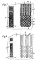
- Fig. 3 shows the corresponding sections of an exposed and developed photoset film, with an increase in line width has occurred, which is within the line width tolerance.
- letter i which is denoted by 2
- a richer letter has been created by adding a contour 9.
- the sum of two opposing contour widths 9 is assumed to be the same size as the line width tolerance.
- the same increase 9 can also be seen in this FIG. 3 for lines 73 and squares 83 of control devices 3 and 4.
- the contours 9 just fill the space 63 and 53 between the grid points 73 and 83 of the control devices 3 and 4, since this distance is the same as the line width tolerance.
- the grid area of the control devices is shown on the photo set film as a full area, which is visually easy to recognize.
- FIG. 4 shows the corresponding section 1 from an exposed and developed photographic set film, a line thickness decrease having just occurred which corresponds to the line width tolerance.
- a narrower letter is formed by omitting a contour 10.
- the sum of the two contours 10 lying opposite one another is the same size as the line width tolerance.
- the the same decrease was also effective on lines 53 and squares 83 of the control devices.
- the contours 10 cause the width of the lines 73 and grid points 83 of the control devices to decrease to zero, so that they disappear.
- the grid area of the control devices is shown on the photo set film as an empty area, which is visually easily recognizable.
- the resolving power as a physical quantity is specified in line pairs per centimeter or per millimeter and thus defines the finest stroke width, which can still be reproduced.
- the resolution of photo typesetting systems and the usual photo typesetting films is usually limited. For this reason, the lines or halftone dots of the control device do not disappear only when the line thickness tolerance falls below or exceeds, but already when the limit set by the resolution requirements is reached.
- the width of the control elements - lines or grid points - is selected in the control device described so that it corresponds to the sum of the two widths, which can be derived on the one hand from the line width tolerance and on the other hand from the resolving power.
- the line width tolerance for a certain font size is ⁇ 6 micrometers.
- the width of the lines and their spacing in the control device would therefore have to be 6 micrometers without taking into account the resolving power.
- the resolving power of the photosetting system used is 500 line pairs per centimeter.
- FIG. 5 shows the first of the control devices 3 from FIG. 1 together with the letter i, designated 2.
- This control device 3 is shown in FIG. 5 as it arises from the control device 3 shown in FIG. 1 by projecting it.
- This control or Grid 3 whose grid points or lines 75 correspond to the line thickness tolerances, a further control or grid 11 is set aside.
- the grid points or lines 12 of this further control or grid field 11 are finer or coarser, but together they form an area with the same tonal value, i.e. with the same area coverage as is the case with the first-mentioned grid 3.
- the smallest diameter of the band-shaped surface elements of the first control device 3 and their smallest distance 55 is larger (twice as large in the present example) than the corresponding surface elements 12 in the additional control field 11.
- the surface elements 75 in their entirety form the first field 3, the surface elements 12 on the other hand, together form the second field 11.
- the area coverage of the two fields 3 and 11 1 with respect to their surface elements 25 and 12 is of the same size, and in the example shown it is practically 50%. This means that the surface elements each cover 50% of the total area of the respective field3 or 11 to which they belong.
- the two fields 3 and 11 can also have a different total area from each other.
- the two grid fields 3 and 11 formed in this way appear in the same brightness level, but they differ in their grid fineness and consequently in their behavior when the line width changes. If a line thickness change occurs during a transfer process in the photo set, then the lines 75 or 12 or grid points of the first as well as of the second grid field 3 or 11 widen or narrow, however, since the grid field with its coarser lines or grid points for geometric reasons has a smaller sum of edge zones per unit area, the change in the line thickness in this coarser grid causes a smaller tonal shift than in the finer grid. As a result, a difference in brightness or tonal value occurs between the two raster fields, which is perceptible to the eye, but which can also be measured with a densitometer. If the first grid is darker than the second, coarser grid, the line width has increased, and if it is lighter, the line width has decreased. If both fields have the same tonal value, there is no change in line width.
Description
Die Erfindung betrifft eine Vorrichtung zur Kontrolle von Strichstärkenänderung von Schriften, welche mit Hilfe einer Fotosatzanlage herstellbar sind.The invention relates to a device for checking the line thickness change of fonts, which can be produced with the aid of a photo typesetting system.
Seit einigen Jahren findet in der grafischen Branche eine beschleunigte Ablösung des Bleisatzes durch den Fotosatz statt. Es lässt sich der Zeitpunkt abschätzen, ab welchem in Mittel-und Westeuropa nur noch Bücher bibliophilen Charakters ab Blei gedruckt werden. Denn die genannte neue Technik bringt den grafischen Betrieben bedeutende Zeit- und Platzersparnisse. Sie bringt jedoch auf der anderen Seite auch neue technische Probleme mit sich. Insbesondere stellt sich das Problem der Qualitätssicherung im Fotosatz anders als im Bleisatz.For some years now, the lead type has been replaced by the typeset in the graphic industry. It is possible to estimate the point in time from which only books of bibliophile character from lead will be printed in Central and Western Europe. Because the new technology mentioned brings significant time and space savings to graphic companies. On the other hand, however, it also brings with it new technical problems. In particular, the problem of quality assurance in photo typesetting is different from that in lead typesetting.
Das Setzen im Fotosatz geschieht heuzutage zur Hauptsache mit Hilfe einer Lichtquelle, eines Schriftspiechers (Fotosatzschriftträger), einer Grössen- und Dickteneinrichtung sowie einer oder zwei Kassetten für das Fotomaterial.The main thing that is set in the photo set nowadays is with the help of a light source, a typewriter (photo typesetter), a size and thickness device and one or two cassettes for the photo material.
Beim Projektionsfotosatz leuchtet eine Lichtquelle (Glühlicht oder Blitzlicht) ein Zeichennegativ aus und projiziert es im gewünschten Massstab über eine Grössenoptik auf fotografisches Material.In the projection photo set, a light source (incandescent or flash light) illuminates a negative of the sign and projects it onto the photographic material at the desired scale using size optics.
Beim Strahlfotosatz baut die Aufzeichnungslichtquelle, die einen lenkbaren Kathoden- oder Laserstrahl enthält, das Zeichen in gewünschter Grösse strich- oder punktweise auf dem Fotomaterial auf. Sie übernimmt das "Fahrprogramm" dabei von einer anderen Lichtquelle, die ein Zeichennegativ abtastet. Es können jedoch auch digital gespeicherte Informationen den Aufzeichnungsstrahl lenken. Beim Strahlfotosatz besteht das belichtete Zeichen (Buchstabe) also aus veilen Strichen bzw. Linien bzw. Punkten, die sich von blossem Auge nur deshalb nicht einzeln ausmachen lassen, weil dessen Auflösungsvermögen dazu nicht ausreicht.In jet photo setting, the recording light source, which contains a steerable cathode or laser beam, builds up the mark in the desired size in lines or dots on the photo material. It takes over the "driving program" from another light source that scans a negative sign. However, digitally stored information can also direct the recording beam. In the case of jet photo typesetting, the exposed sign (letter) consists of veil lines or lines or dots that cannot be identified individually by the naked eye only because its resolving power is not sufficient for this.
Untersucht man die qualitätsbestimmenden Merkmale der Schriftwiedergabe, so findet man zwei Gruppen von Mängeln: Eine erste Gruppe umfasst Fehler in der Positionierung der Schriftzeichen, eine zweite Gruppe die Deformation der Schriftzeichen. Positionierungsfehler sind schiefe Buchstaben, schlechte Zeilenhaltung, unregelmässige Buchstabenabstände (Dickten) und unregelmässiger Durchschuss. Die Deformation der Schrift wirkt sich als Eckenabrundung, verbunden mit einem Verlust der Innen- und Aussenformen, als Abbrechen von Serifen, als Konturunschärfe und als Strichstärkenänderung.If one examines the quality-determining characteristics of the font rendering, two groups of defects are found: a first group includes errors in the positioning of the characters, a second group the deformation of the characters. Positioning errors are crooked letters, poor line alignment, irregular letter spacing (Dickten) and irregular weft. The deformation of the font acts as a rounded corner, combined with a loss of the inside and outside shapes, as a breaking off of serifs, as a contour blur and as a change in line width.
Unerwünschte Strichstärkenänderungen haben zur Folge, dass einzelne Buchstaben, Wörter, Zeilen oder ganze Textabschnitte und Textseiten fetter oder magerer erscheinen als beabsichtigt. Drucksachen, welche derartige Mängel aufweisen, wirken ungepflegt, zudem wird die Lesbarkeit herabgesetzt, weil der Leser unsicher wird, ob eine fettere Zeile eine beabsichtigte Hervorhebung im Text bedeutet oder auf einen unbeabsichtigten technischen Mangel zurückzuführen ist. Die Vermeidung unerwünschter und ausserhalb der vom Auge noch akzeptierten Toleranz liegender Strichstärkenänderungen ist deshalb in der Qualitätssicherung des Fotosatzes von grosser Bedeutung.Undesired changes in the weight of the line result in individual letters, words, lines or entire text sections and text pages appearing bolder or leaner than intended. Printed matter that has such defects appears neglected, and legibility is reduced because the reader is unsure whether a bold line means an intentional highlighting in the text or is due to an unintentional technical defect. Avoiding unwanted line thickness changes that are still outside the tolerance accepted by the eye is therefore of great importance in the quality assurance of the photo set.
Strichstärkenänderungen können auf verschiedenen Produktionsstufen auftreten: Das optische System der Belichtungseinheit der Fotosatzanlage kann Mängel aufweisen und demzufolge unregelmässige Ergebnisse liefern, die Lichtquelle selber kann Schwankungen oder Alterungserscheinungen unterliegen, was sich meist unverzüglich als Strichstärkenänderung im Satz auswirkt. lm weiteren kann die verwendete Fotosatzfilmemulsion Schwankungen aufweisen oder die Filmentwicklung kann zu unterschiedlichen Resultaten führen, was wiederum als Strichstärkenänderung in Erscheinung tritt. Bei der Kopie des Fotosatzfilmes auf die Offsetdruckplatte können ebenfalls Strichstärkenänderungen auftreten, ebenso beim nachfolgenden Druckvorgang selber.Line thickness changes can occur at different stages of production: The optical system of the exposure unit of the photo typesetting system can have defects and consequently deliver irregular results, the light source itself can be subject to fluctuations or signs of aging, which usually has an immediate effect as a line thickness change in the set. Furthermore, the photoset film emulsion used can fluctuate or the film development can lead to different results, which in turn appears as a change in the line thickness. When copying the photoset film onto the offset printing plate, changes in line thickness can also occur, as can the subsequent printing process itself.
Für die Messung von Strichstärkenänderungen im Fotosatz sind im wesentlichen zwei Methoden bekannt:
- 1) die messmikroskopische Methode und
- 2) die densitometrische Methode.
- 1) the measuring microscopic method and
- 2) the densitometric method.
Bei der messmikroskopischen Methode wird ein Mikroskop verwendet, welches rund 100- fach oder mehr vergrössert und welches eine Messeinteilung von 0,01 mm oder feiner besitzt. Damit kann die Strichbreite von Buchstaben direkt gemessen werden. Die Methode ist geeignet um die Toleranzen der Strichstärkenänderung, welche vom Auge des Lesers noch akzeptiert wird, zu ermitteln. Zur Ueberwachung der einmal festgelegten Toleranzen in der täglichen Betriebspraxis ist die Methode jedoch umständlich und aufwendig. Mikroskope mit 100-facher Vergrösserung sind bereits Laborinstrumente und für Fachleute des Fotosatzes ungewohnt. Das Gesichtsfeld ist dabei so klein, dass davon in der Regel nicht einmal ein ganzer Buchstabe erfasst wird, was das Aufsuchen geeigneter Messstellen in der Schrift erschwert.In the measurement microscopic method, a microscope is used which is magnified around 100 times or more and which has a measurement graduation of 0.01 mm or finer. This enables the stroke width of letters to be measured directly. The method is suitable to determine the tolerances of the line thickness change, which is still accepted by the eye of the reader. However, the method is laborious and time-consuming to monitor the tolerances once established in daily operating practice. Microscopes with 100x magnification are already laboratory instruments and unusual for photo typesetting experts. The field of view is so small that it does not usually capture an entire letter, which makes it difficult to find suitable measuring points in the script.
Die densitometrische Methode beruht auf der Erkenntnis, dass Schriftverbreiterung und Rasterpunktverbreiterung die gleichen Ursachen haben und demzufolge mit den gleichen Messmethoden erfasst werden können. Eine Rasterpunktverbreiterung bewirkt, dass ein Rasterfeld dunkler wird und demzufolge bei der Messung mit dem Densitometer einen höheren Dichtewert angibt.The densitometric method is based on the knowledge that the widening of the font and the widening of the halftone dot have the same causes and can therefore be measured using the same methods. A widening of the halftone dot causes a halftone field to become darker and consequently indicates a higher density value when measured with the densitometer.
Bringt man auf dem Fotosatzschriftträger an der Stelle, die sonst ein Buchstabennegativ einnehmen würde, ein geeignetes Rasterfeld, z.B. ein Mikromessfeld, und belichtet ein solches Rasterfeld in der gleichen Weise wie ein Buchstabe auf den Fotosatzfilm, so kann diese Feld nach dem Entwickeln mit einem Densitometer gemessen werden. Bei einer stärkeren Belichtung, welche eine Strichstärkenzunahme der Buchstaben einerseits und ein Dunklerwerden des Rasterfeldes andererseits zur Folge hat, zeigt das Densitometer einen höheren Wert an. Bei einer schwächeren Belichtung, welche eine Strichstärkenabnahme und ein Hellerwerden das Rasterfeldes zur Folge hat, erscheint am Densitometer ein niedrigerer Dichtewert.If a suitable grid, for example a micro measuring field, is placed on the photo record carrier at the place that would otherwise take up a letter negative, and one is exposed Grid in the same way as a letter on the photoset film, so this field can be measured after development with a densitometer. With a stronger exposure, which results in an increase in the line thickness of the letters on the one hand and a darkening of the grid on the other hand, the densitometer shows a higher value. With a weaker exposure, which results in a decrease in the line thickness and a brightening of the grid, a lower density value appears on the densitometer.
Die beiden beschriebenen Messmethoden sind geeignet, um einerseits Standardwerte für die Strichstärke festzulegen und andererseits die vom Auge noch akzeptierten Toleranzen der Strichstärkenänderung zu ermitteln. Es verden Toleranzwerte festgelegt, was mit Hilfe von Testreihen geschieht.The two measurement methods described are suitable, on the one hand, for defining standard values for the line width and, on the other hand, for determining the tolerances of the line width change which are still accepted by the eye. Tolerance values are defined, which is done with the help of test series.
Eine solche Testreihe kann folgendermassen hergestellt werden: Für eine bestimmte Schriftart und -grösse wird durch Versuche zuerst diejenige Strichstärke festgelegt, welche ein optimales Schriftbild in bezug auf Lesbarkeit und Aussehen ergibt. Mit der festgelegten Strichstärke werden mehrere Fotosatztextblöcke belichtet. Innerhalb dieser Textblöcke werden einzelne Zeilen jedoch gezielt mit anderen Belichtungszeiten belichtet, so dass diese Zeilen entweder magerer oder fetter erscheinen als der übrige Text. Testpersonen bestimmen dann die kritische Strichstärkenänderung, bei welcher fettere oder magerere Zeilen oder Texte für das Auge störend in Erscheinung treten.Such a series of tests can be produced as follows: For a certain font and size, tests first determine the line width that results in an optimal typeface in terms of legibility and appearance. With the specified line width, several photo text blocks are exposed. Within these text blocks, however, individual lines are deliberately exposed with different exposure times, so that these lines either appear leaner or fatter than the rest of the text. Test persons then determine the critical change in the line thickness at which fatter or leaner lines or texts are disruptive to the eye.
Die kritische Strichstärkenänderung, welche in der Folge Strichstärkentoleranz genannt werden soll, ändert sich geringfügig von Schriftart zu Schriftart und auch mit dem Schriftgrad. Grössere Grade erlauben eine etwas grössere Strichstärkentoleranz als kleinere. Die Strichstärkentoleranz kann in Mikrometern oder in Dichtedifferenzen an einem definierten Rasterfeld angegeben werden.The critical line thickness change, which will subsequently be called line thickness tolerance, changes slightly from font to font and also with the font size. Larger grades allow a slightly larger line width tolerance than smaller ones. The line thickness tolerance can be specified in micrometers or in density differences on a defined grid.
Sollwert und Toleranz der Strichstärke können für jede Schriftart und jeden Grad nach den beschriebenen Methoden festgelgt werden. Da es sich dabei jeweilen un eine einmalige Aufgabe handelt, fällt der notwendige Aufwand und Zeitbedarf nicht ins Gewicht. Anders verhält es sich jedoch mit der täglichen Ueberwachung der einmal festgelegten Sollwerte und Toleranzen in der Betriebspraxis des Fotosatzes. Hier erscheinen die genannten Methoden wegen der notwendigen täglichen Wiederholung mühsam und aufwendig. In der Praxis besteht deshalb das Bedürfnis nach einer Vorrichtung, welche es erlaubt, die Kontrolle der Sollwerte und Toleranzen rasch und mit einfachen Mitteln durchzuführen.The target value and tolerance of the line width can be determined for each font and each degree using the methods described. Since this is a unique task, the effort and time required are negligible. However, the situation is different with the daily monitoring of the setpoints and tolerances once established in the operational practice of the photo set. The methods mentioned appear tedious and time-consuming because of the necessary daily repetition. In practice, therefore, there is a need for a device which allows the control of the target values and tolerances quickly and with simple means.
Es sind bereits Vorrichtungen zur Kontrolle der Qualität eines aus Rasterpunkten bestehenden, in einem Reproduktions- und Druckverfahren zu verarbeitenden und auf einem Träger befindlichen Bildes bekannt, die aus wenigstens einem Meßelement mit wenigstens einem Meßsymbol bestehen, das so ausgebildet ist, daß das Verschwinden eines Teils desselben unmittelbar ein Maß für die relative Flächenvergrößerung der Rasterpunkte des Bildes ist (CH-PS 554 751). Derartige Vorrichtungen lassen sich jedoch nicht ohne weiteres auf die Kontrolle der Sollwerte und Toleranzen der Schriftstärke beim Fotosatz anwenden, weil Fotosatzschriften nicht wie Bilder aus einer Vielzahl von einzelnen Rasterpunkten bestehen und weil beim Fotosatz andere Kriterien als bei der Reproduktion oder beim Druck zu beachten sind.Devices for checking the quality of an image consisting of halftone dots, to be processed in a reproduction and printing process and located on a support are already known, which consist of at least one measuring element with at least one measuring symbol which is designed such that the disappearance of a part it is a direct measure of the relative enlargement of the grid points of the image (CH-PS 554 751). However, such devices cannot readily be used to check the setpoints and tolerances of the font size in the photo set, because photo set fonts do not consist of a large number of individual halftone dots like pictures and because other criteria have to be taken into account in the photo set than when reproducing or printing.
Der Erfindung liegt die Aufgabe zugrunde, eine Vorrichtung zur raschen und einfachen Kontrolle der Schriftstärkenänderung einer mit einer Fotosatzanlage herstellbaren Fotosatzschrift zu schaffen.The invention has for its object to provide a device for quick and easy control of the font thickness change of a photo typesetting that can be produced with a photo typesetting system.
Zur Lösung dieser Aufgabe ist die erfindungsgemäße Vorrichtung gekennzeichnet durch ein helles Kontrollfeld mit mehr als einem dunklen Flächenelement, wobei der kleinste Abstand von wenigstens zwei Flächenelementen und die kleinste Breite der Flächenelemente so gewählt sind, daß bei Überschreiten einer vorgegebenen Schriftstärkentoleranz der Abstand zwischen den Flächenelementen und bei Unterschreiten dieser Toleranz die Flächenelemente verschwinden.To achieve this object, the device according to the invention is characterized by a bright control field with more than one dark surface element, the smallest distance of at least two surface elements and the smallest width of the surface elements being selected such that the distance between the surface elements and is exceeded when a given tolerance for font size is exceeded if the tolerance falls below this, the surface elements disappear.
Weitere vorteilhafte Merkmale der Erfindung sind in den Unteransprüchen gekennzeichnet.Further advantageous features of the invention are characterized in the subclaims.
Die Erfindung schafft erstmals eine Kontrollvorrichtung, mittels derer beim Fotosatz das Erreichen der oberen und unteren Schriftstärkentoleranz unmittelbar sichtbar gemacht werden kann. Eine solche Vorrichtung kann daher in vorteilhafter und einfacher Weise dazu benutzt werden, jedem Schrifttyp eine eigene, von seinen speziellen Eigentümlichkeiten abhängige Toleranz zuzuordnen und auf diese Weise sicherzustellen, daß beim Fotosatz jeder Schrifttyp innerhalb der ihm zugeordneten Toleranz wiedergegeben wird.The invention creates for the first time a control device, by means of which the reaching of the upper and lower tolerance for the font thickness can be made immediately visible in the typesetting. Such a device can therefore be used in an advantageous and simple manner to assign each font type its own tolerance, which depends on its special peculiarities, and in this way to ensure that each font type is reproduced within the tolerance assigned to it in the photo set.
Nachstehend werden Ausführungsbeispiele der vorliegenden Erfindung anhand der beiliegenden Zeichnungen näher erläutert. Es zeigt:
- Fig. 1 in starker Vergrößerung einen Ausschnitt aus einem Fotosatzschriftträger, welcher den Buchstaben "i" sowie zwei Ausführungsformen der vorliegenden Kontrollvorrichtung trägt,
- Fig. 2 denselben Ausschnitt, der sich nun auf einem belichteten und entwickelten Fotosatzfilm befindet, wobei dieser Ausschnitt durch Projektion enstanden ist,
- Fig. 3 den Ausschnitt nach Fig. 2, bei welchem eine Strichstärkenzunahme eingetreten ist,
- Fig. 4 einen Ausschnitt nach Fig. 2, bei welchem eine Strichstärkenabnahme eingetreten ist,
- Fig. 5 in starker Vergrößerung eine weitere Ausführungsform der vorliegenden Kontrollvorrichtung, welche ähnlich wie die Vorrichtung nach Fig. 2 durch Projektion enstanden ist, und
- Fig. 6 die Vorrichtung nach Fig. 5, bei welcher eine Strichstärkenzunahme eingetreten ist.
- 1 is a large enlargement of a section of a photo record carrier, which carries the letter "i" and two embodiments of the present control device,
- 2 the same section, which is now on an exposed and developed photo-set film, this section being created by projection,
- 3 shows the detail according to FIG. 2, in which an increase in line thickness has occurred,
- 4 shows a detail according to FIG. 2, in which a decrease in the line thickness has occurred,
- Fig. 5 in high magnification another embodiment of the present control device, which is similar to the
device 2 is created by projection, and - Fig. 6 shows the device of Fig. 5, in which an increase in line thickness has occurred.
In Fig. 1 ist ein Ausschnitt aus einem Fotosatzschriftträger 1 in starker Vergrößerung dargestellt. Auf diesem Träger 1, der meist aus Glas ist, sind ein Buchstabe i, bezeichnet mit 2, sowie zwei mögliche Ausführungsformen 3 und 4 der vorliegenden Kontrollvorrichtung dargestellt. Die schwarzen Flächen 5 bzw. 6 sind bei diesen Kontrollvorrichtungen lichtundurchlässig, die weißen Flächen 7 bzw. 8 sind hingegen transparent.In Fig. 1 a section of a photo record carrier 1 is shown in a large magnification. On this carrier 1, which is usually made of glass, a letter i, designated by 2, and two
Die erste Ausführungsform 3 der Kontrollvorrichtung hat die Form eines Linienrasters. Die zweite Ausführungsform 4 der Kontrollvorrichtung hat die Form eines sogenannten Quadratrasters. Die Breite der deckenden und der transparenten Linien bzw. Quadrate dieser Kontrollvorrichtungen ist dabei gleich gross wie die Strichstärkentoleranz derjenigen Schriftart, welche auf dem betreffenden Fotosatzschriftträger vorhanden ist.The
Aus Fig. 1 ist ferner ersichtlich, dass die Breite der deckenden und der transparenten Linien 5,7 bzw. Quadrate 6,8 dieser Kontrollvorrichtung praktisch 1/3 der Breite des Buchstabens i beträgt. Die Länge der Linien 5 bzw. 7 bei der ersten Ausführungsform der vorliegenden Kontrollvorrichtung ist zwar kleiner als die Höhe des jeweiligen Buchstabens 2, diese Länge kann jedoch entweder gleich gross oder unter Umständen sogar grösser als die Höhe des Buchstabens sein.From Fig. 1 it can also be seen that the width of the opaque and
Was die Anzahl dieser Linien 5 bzw. 7 anbelangt, sind selbstverständlich wenigstens zwei Flächenelemente 5 bzw. 7 erforderlich. Es versteht sich wohl, dass die Kontrolle der Strichstärkenänderung umso leichter erfolgen kann, je mehr Linien 5 und 7 bzw. Quadrate 6 und 8 die jeweilige Kontrollvorrichtung enthält.As far as the number of these
Wie ersichtlich, enthält die vorliegende Kontrollvorrichtung wenigstens ein Rasterfeld 3 bzw. 4, dessen Rasterpunkte 6 bzw. 8 oder Rasterlinien 5 bzw. 7 in bezug auf deren Breite und deren kleinste Abstände genau der Strichstärkentoleranz entsprechen. Dieses Rasterfeld 3 bzw. 4 wird beim Fotosetzen wei ein Buchstabe am Ende einer Zeile oder einer Textspalte auf dem Fotosatzschriftträger 1 mitbelichtet und mite,itwickelt. Tritt während der Belichtung und Entwicklung des Fotosatzfilmes eine Strichstärkenzunahme ein, welche die kritische Grenze, also die Strichstärkentoleranz erreicht, so verbreitern sich gleichzeitig die feinen Linien oder Rasterpunkte im Rasterfeld der Kontrollvorrichtung in der Weise, dass die Zwischenräume gerade gefüllt werden, und das Feld dadurch zu einer schwarzen Vollfläche wird, was von blossem Auge oder mit einer Lupe einfach festgestellt werden kann.As can be seen, the present control device contains at least one
Tritt umgekehrt bei der Belichtung und Entwicklung des Fotosatzfilmes eine Strichstärkenabnahme ein, welche die untere Toleranzgrenze erreicht, so verschmälern sich die feinen Linien oder Rasterpunkte im Rasterfeld der Kontrollvorrichtung soweit, dass diese vollständig verschwinden, was ebenfalls einfach festgestellt werden kann.Conversely, if there is a decrease in the line thickness in the exposure and development of the photoset film, which reaches the lower tolerance limit, the fine lines or halftone dots in the grid of the control device become so narrow that they disappear completely, which can also be easily determined.
Die Kontrollvorrichtung erlaubt damit, Mängel im Fotosatzfilm in bezug auf die Strichstärkentoleranz unmittelbar nach dem Entwickeln des Filmes zu erkennen. Infolgedessen kann ein solcher Fotosatzfilm vor der Weiterverarbeitung rechtzeitig ausgeschieden werden, während sonst der Mangel meist erst am fertigen Druckresultat erkennbar wird, wobei dann der Schaden viel grösser ist. Die vorliegende Kontrollvorrichtung erlaubt auch eine Beurteilung wie ein als fehlerhaft erkannter Fotosatzfilm wiederholt werden muss, damit der festgestellte Mangel in der Wiederholung nicht mehr vorhanden ist.The control device thus allows defects in the photosetting film to be recognized with regard to the line thickness tolerance immediately after the film has been developed. As a result, such a photo replacement film can be eliminated in good time before further processing, whereas otherwise the defect can usually only be recognized from the finished print result, in which case the damage is much greater. The present control device also allows an assessment as to how a photoset film identified as defective must be repeated so that the identified defect is no longer present in the repetition.
Diese nun geschilderte Anwendungsweise der vorliegenden Kontrollvorrichtung sowie eine noch weitere Ausführungsform derselben werden nun noch näher beschrieben und erörtert.This now described application of the present control device and a still further embodiment of the same will now be described and discussed in more detail.
Fig. 2 zeigt ein Teilstück aus einem belichteten und entwickelten Fotosatzfilm, welcher durch Projektion des Musters nach Fig. 1 entstanden ist. In diesem Fall trat keine Strichstärkenänderung auf, und deswegen sind die Breiten sowohl des Buchstaben i als auch der abgebildeten Kontrollvorrichtungen 3 und 4 unverändert, jedoch im fotografischen Sinne positiv. Die abgebildeten Kontrollvorrichtungen 3 und 4 sind noch als Rasterfeld vorhanden.FIG. 2 shows a section of an exposed and developed photo-setting film, which was created by projecting the pattern according to FIG. 1. In this case there was no change in the line thickness and therefore the widths of both the letter i and the
Fig. 3 zeigt das entsprechende Teilstücke aus einem belichteten und entwickelten Fotosatzfilm, wobei eine Strichstärkenzunahme eingetreten ist, welche in der Strichstärkentoleranz liegt. Aus dem Buchstaben i, welcher mit 2 bezeichnet ist, ist durch Hinzukommen einer Kontur 9 ein fetterer Buchstabe entstanden. Die Summe von zwei einander gegenüberliegenden Konturbreiten 9 ist dabei gleich gross angenommen, wie die Strichstärkentoleranz. Die gleiche Zunahme 9 ist in dieser Fig. 3 auch bei den Linien 73 und den Quadraten 83 der Kontrollvorrichtungen 3 und 4 feststellbar. Die Konturen 9 füllen dabei gerade den Zwischenraum 63 bzw. 53 zwischen den Rasterpunkten 73 bzw. 83 der Kontrollvorrichtungen 3 und 4 aus, da ja dieser Abstand gleich gross ist, wie die Strichstärkentoleranz. Die Rasterfläche der Kontrollvorrichtungen wird dabei auf dem Fotosatzfilm als Vollfläche abgebildet, was optisch leicht zu erkennen ist.Fig. 3 shows the corresponding sections of an exposed and developed photoset film, with an increase in line width has occurred, which is within the line width tolerance. From letter i, which is denoted by 2, a richer letter has been created by adding a
Fig. 4 zeigt das entsprechende Teilstück 1 aus einem belichteten und entwickelten Fotosatzfilm, wobei eine Strichstärkenabnahme eingetreten ist, welche gerade der Strichstärkentoleranz entspricht. Aus dem Buchstaben i, bezeichnet mit 2, ist durch Wegfallen einer Kontur 10 ein schmälerer Buchstabe entstanden. Die Summe der beiden einander gegenüber liegenden Konturen 10 ist dabei gleich gross, wie die Strichstärkentoleranz. Die gleiche Abnahme wurde auch an den Linien 53 und Quadraten 83 der Kontrollvorrichtungen wirksam. Die Konturen 10 bewirken dabei, dass die Breite der Linien 73 und Rasterpunkte 83 der Kontrollvorrichtungen auf Null sinkt, so dass diese verschwinden. Die Rasterfläche der Kontrollvorrichtungen wird dabei auf dem Fotosatzfilm als Leerfläche abgebildet, was optisch leicht erkennbar ist.FIG. 4 shows the corresponding section 1 from an exposed and developed photographic set film, a line thickness decrease having just occurred which corresponds to the line width tolerance. From the letter i, designated 2, a narrower letter is formed by omitting a
In den vorstehend beschriebenen einfachen Fällen wird von der Annahme ausgegangen, das Zusammenfallen bzw. Wegfallen der Linien bzw. der Rasterelemente der Kontrollvorrichtungen geschehe allein auf Grund einer Strichstärkenzunahme oder -abnahme bei der Belichtung und Weiterverarbeitung des Fotosatzfilmes. Dieser einfachste Fall setzt voraus, dass das Auflösungsvermögen des optischen Systems der Fotosatzanlage sowie das Auflösungsvermögen der verwendeten fotografischen Schichten unendlich hoch sei, oder mindestens sehr viel höher liegt, als die Strichstärkentoleranz.In the simple cases described above, it is assumed that the lines or the raster elements of the control devices collapse or disappear solely on the basis of an increase or decrease in the line width during the exposure and further processing of the photoset film. This simplest case assumes that the resolving power of the optical system of the photosetting system and the resolving power of the photographic layers used are infinitely high, or at least much higher than the line thickness tolerance.
Das Auflösungsvermögen als physikalische Grösse wird bekanntlich in Linienpaaren pro Zentimeter oder pro Millimeter angegeben und definiert damit die feinste Strichbreite, welche noch wiedergegeben werden kann. Das Auflösungsvermögen von Fotosatzanlagen und der üblichen Fotosatzfilme ist in der Regel beschränkt. Aus diesem Grunde verschwinden die Linien oder Rasterpunkte der Kontrollvorrichtung nicht erst dann, wenn die Strichstärkentoleranz unter bzw. überschritten, sondern bereits dann, wenn die durch das Auflösungsvormögen gesetzte Grenze erreicht wird. Um diesem Umstande Rechnung zu tragen, wird in der beschriebenen Kontrollvorrichtung die Breite der Kontrollelemente - Linien oder Rasterpunkte - so gewählt, dass diese der Summe der beiden Breiten entspricht, welche sich einerseits aus der Strichstärkentoleranz und andererseits aus dem Auflösungsvermögen ableiten lassen.As is known, the resolving power as a physical quantity is specified in line pairs per centimeter or per millimeter and thus defines the finest stroke width, which can still be reproduced. The resolution of photo typesetting systems and the usual photo typesetting films is usually limited. For this reason, the lines or halftone dots of the control device do not disappear only when the line thickness tolerance falls below or exceeds, but already when the limit set by the resolution requirements is reached. In order to take this into account, the width of the control elements - lines or grid points - is selected in the control device described so that it corresponds to the sum of the two widths, which can be derived on the one hand from the line width tolerance and on the other hand from the resolving power.
Ein Beispiel soll diesen Sachverhalt näher erläutern: Die Strichstärkentoleranz für einen bestimmten Schriftgrad betrage ± 6 Mikrometer. Die Breite der Linien und deren Abstände in der Kontrollvorrichtung müsste ohne Berücksichtigung des Auflösungsvermögens demzufolge 6 Mikrometer betragen. Das Auflösungsvermögen des angewandten Fotosatzsystems betrage 500 Linienpaare pro Zentimeter.An example should explain this fact in more detail: The line width tolerance for a certain font size is ± 6 micrometers. The width of the lines and their spacing in the control device would therefore have to be 6 micrometers without taking into account the resolving power. The resolving power of the photosetting system used is 500 line pairs per centimeter.
Ein Linienpaar, das gerade noch abgebildet werden kann, hat demzufolge eine Gesamtbreite von 20 Mikrometer, die einzelne positive oder negative Linie demzufolge eine solche von 10 Mikrometer. Feinere Linien können nicht mehr abgebildet werden, sie verschwinden oder fallen zu einer Fläche zusammen. Die Strichbreite der Linien oder der Durchmesser der Rasterpunkte in der Kontrollvorrichtung muss demzufolge 6 plus 10 = 16 Mikrometer betragen.A line pair that can just be mapped therefore has a total width of 20 micrometers, and the individual positive or negative line accordingly has a width of 10 micrometers. Finer lines can no longer be mapped, they disappear or collapse into a surface. The line width of the lines or the diameter of the screen dots in the control device must therefore be 6 plus 10 = 16 micrometers.
Eine weitere Ausführungsform der vorliegenden Kontrollvorrichtung ist in Fig. 5 und 6 dargestellt. In Fig. 5 ist die erste der Kontrollvorrichtungen 3 aus Fig. 1 samt dem Buchstaben i, bezeichnet mit 2, dargestellt. Diese Kontrollvorrichtung 3 ist in Fig. 5 so abgebildet, wie sie aus der in Fig. 1 dargestellten Kontrollvorrichtung 3 durch Projektion dieser entsteht. Diesem Kontroll-bzw. Rasterfeld 3, dessen Rasterpunkte oder -linien 75 den Strichstärkentoleranzen entsprechen, wird ein weiteres Kontroll- bzw. Rasterfeld 11 an die Seite gestellt. Die Rasterpunkte oder -linien 12 dieses weiteren Kontroll- bzw. Rasterfeldes 11 sind zwar feiner oder gröber, sie bilden jedoch zusammen eine Fläche mit gleichem Tonwert, d.h. mit gleicher Flächenbedeckung, wie das beim erstgenannten Rasterfeld 3 der Fall ist. Der kleinste Durchmesser der bandförmigen Flächenelemente der ersten Kontrollvorrichtung 3 und deren kleinster Abstand 55 ist grösser (im vorliegenden Beispiel doppelt so gross) als die entsprechenden Flächenelemente 12 im zusätzlichen Kontrollfeld 11. Die Flächenelemente 75 bilden in ihrer Gesamtheit das erste Feld 3, die Flächenelemente 12 bilden dagegen zusammen das zweite Feld 11. Die Flächenbedeckung der beiden Felder 3 und 11 1 in bezug auf ihre Flächenelemente 25 bzw. 12 ist gleich gross, und im dargestellten Beispiel beträgt sie praktisch 50%. Dies bedeutet, dass die Flächenelemente je 50% der Gesamtfläche des jeweiligen Feldes3 bzw. 11 bedecken, dem sie zugehören. Die beiden Felder 3 und 11 können aber auch eine voneinander unterschiedliche Gesamtfläche besitzen.Another embodiment of the present control device is shown in FIGS. 5 and 6. FIG. 5 shows the first of the
Visuell erscheinen die beiden solchermassen ausgeformten Rasterfelder 3 und 11 in der gleichen Helligkeitsstufe, sie unterscheiden sich jedoch durch ihre Rasterfeinheit und demzufolge in ihrem Verhalten bei Strichstärkenänderungen. Tritt mämlich während eines Uebertragungsvorganges im Fotosatz eine Strichstärkenveränderung ein, so verbreitern oder verschmälern sich sowohl die Linien 75 bzw. 12 oder Rasterpunkte des ersten wie auch des zweiten Rasterfeldes 3 bzw. 11. Da jedoch das Rasterfeld mit seinen gröberen Linien oder Rasterpunkten aus geometrischen Gründen eine geringere Summe von Randzonen pro Flächeneinheit aufweist, bewirkt die Strichstärkenveränderung in diesem gröberen Rasterfeld eine geringere Tonwertverschiebung als im feineren Rasterfeld. Demzufolge tritt zwischen den beiden Rasterfeldern ein Helligkeits- oder Tonwertunterschied auf, welcher vom Auge wahrgenommen wird, welcher aber auch mit einem Densitometer gemessen werden kann. Wird das erste Rasterfeld gegenüber dem zweiten gröberen Rasterfeld dunkler, so ist eine Strichstärkenzunahme erfolgt, wird es umgekehrt heller, ist eine Strichstärkenabnahme erfolgt. Behalten beide Felder den gleichen Tonwert, so ist keine Strichstärkenveränderung eingetreten.Visually, the two
Da im Feld 11 die sogenannte Summe der Randzone der Flächenelemente grösser ist (im dargestellten Beispiel doppelt so gross) als im Feld 3, bewirkt die gleiche Strichstärkenzunahme in diesem Feld eine stärkere Flächenzunahme als im benachbarten Feld 3, und demzufolge auch ein stärkeres Dunklerwerden. Fig 6 soll diesen Sachverhalt deutlicher machen. Aus dem Buchstaben i, der mit 2 bezeichnet ist, ist durch das Hinzukommen einer Kontur 9 ein fetterer Buchstabe geworden. Die gleichen Konturen 9 sind auch bei den bandförmigen Flächenelementen 53 bzw. 12 der Felder 3 und 11 hinzugekommen. Da das Feld 11 jedoch mehr Flächenelemente 12 besitzt, (doppelt so viele) wie das erste Feld 3, erfährt es eine stärkere Tonwertzunahme durch diese hinzugefügten Konturen als das Feld 3. Der Tonwertunterschied ist visuell oder densitometrisch feststellbar und dient als Mass für die Strichstärkenänderung.Since in
Claims (5)
Applications Claiming Priority (2)
| Application Number | Priority Date | Filing Date | Title |
|---|---|---|---|
| CH808377 | 1977-06-30 | ||
| CH8083/77 | 1977-06-30 |
Publications (2)
| Publication Number | Publication Date |
|---|---|
| EP0000202A1 EP0000202A1 (en) | 1979-01-10 |
| EP0000202B1 true EP0000202B1 (en) | 1981-11-25 |
Family
ID=4334887
Family Applications (1)
| Application Number | Title | Priority Date | Filing Date |
|---|---|---|---|
| EP78100279A Expired EP0000202B1 (en) | 1977-06-30 | 1978-06-29 | Device for controlling the line width variation of characters produced by a photographic composing apparatus |
Country Status (3)
| Country | Link |
|---|---|
| US (1) | US4183659A (en) |
| EP (1) | EP0000202B1 (en) |
| DE (1) | DE2861347D1 (en) |
Families Citing this family (12)
| Publication number | Priority date | Publication date | Assignee | Title |
|---|---|---|---|---|
| DE2862298D1 (en) * | 1978-11-29 | 1983-08-25 | Hell Rudolf Dr Ing Gmbh | Method for visually testing the reproduction quality of printed matter obtained by cathode ray tube composition |
| DE2939681A1 (en) * | 1979-09-29 | 1981-04-30 | Agfa-Gevaert Ag, 5090 Leverkusen | METHOD AND DEVICE FOR MONITORING THE QUALITY IN THE PRODUCTION OF PHOTOGRAPHIC IMAGES |
| WO1982000368A1 (en) * | 1980-07-15 | 1982-02-04 | Kehl C | Method for checking the quality of reproduction of graphic elements |
| US4419426A (en) * | 1982-03-05 | 1983-12-06 | Dr. -Ing. Rudolf Hell Gmbh | Method for the visual inspection of the reproduction quality of drawing elements and elements for the execution of the method |
| US4566192A (en) * | 1983-12-28 | 1986-01-28 | Harris Corporation | Critical dimension measurement structure |
| US4527333A (en) * | 1984-01-23 | 1985-07-09 | Graphic Arts Technical Foundation | Device for indicating a quantitative change in dot area of an image in a printing process and the method of making the same |
| EP0437867B1 (en) * | 1990-01-19 | 1995-09-13 | Agfa-Gevaert N.V. | Measuring strip |
| US5311246A (en) * | 1992-08-26 | 1994-05-10 | Graphic Arts Technical Foundation | Frequency modulated acutance guide and method of use |
| ES2119928T3 (en) * | 1993-04-30 | 1998-10-16 | Hewlett Packard Co | ALIGNMENT SYSTEM FOR MULTIPLE INK JET PRINTER CARTRIDGES. |
| JPH06340065A (en) * | 1993-04-30 | 1994-12-13 | Hewlett Packard Co <Hp> | Ink jet cartridge arranging method |
| US5404020A (en) * | 1993-04-30 | 1995-04-04 | Hewlett-Packard Company | Phase plate design for aligning multiple inkjet cartridges by scanning a reference pattern |
| US5451990A (en) * | 1993-04-30 | 1995-09-19 | Hewlett-Packard Company | Reference pattern for use in aligning multiple inkjet cartridges |
Family Cites Families (7)
| Publication number | Priority date | Publication date | Assignee | Title |
|---|---|---|---|---|
| US1808123A (en) * | 1927-07-29 | 1931-06-02 | Jr Edmund Uher | Method of producing photographed printing forms |
| US3220301A (en) * | 1960-07-11 | 1965-11-30 | Magnavox Co | Coding and photographing device |
| US3620622A (en) * | 1968-06-18 | 1971-11-16 | Norton Goodwin | Microphotographic record and method |
| US3631772A (en) * | 1969-07-09 | 1972-01-04 | Bell Telephone Labor Inc | Method and apparatus for characterizing photoresist |
| US3785733A (en) * | 1973-01-29 | 1974-01-15 | Logetronics Inc | Method of calibrating a graphic arts camera |
| CH554751A (en) * | 1973-03-08 | 1974-10-15 | Brunner Felix | DEVICE FOR CONTROLLING THE IMAGE QUALITY OF AN IMAGE TO BE PROCESSED IN A REPRODUCTION PROCESS. |
| US3998639A (en) * | 1974-11-19 | 1976-12-21 | Bell Telephone Laboratories, Incorporated | Methods for determining feature-size accuracy of circuit patterns |
-
1978
- 1978-06-27 US US05/919,575 patent/US4183659A/en not_active Expired - Lifetime
- 1978-06-29 EP EP78100279A patent/EP0000202B1/en not_active Expired
- 1978-06-29 DE DE7878100279T patent/DE2861347D1/en not_active Expired
Also Published As
| Publication number | Publication date |
|---|---|
| US4183659A (en) | 1980-01-15 |
| DE2861347D1 (en) | 1982-01-28 |
| EP0000202A1 (en) | 1979-01-10 |
Similar Documents
| Publication | Publication Date | Title |
|---|---|---|
| DE69816350T2 (en) | Technique for the detection of imaging errors | |
| DE3708147C2 (en) | ||
| EP0000202B1 (en) | Device for controlling the line width variation of characters produced by a photographic composing apparatus | |
| EP0020897B1 (en) | Device for determining the optimum scanning angle of printed matter | |
| DE2820965A1 (en) | PHOTOGRAPHIC COPY DEVICE | |
| DE2401672C3 (en) | Device for controlling the image quality of an image to be processed in a reproduction and printing process and method for producing the device | |
| DE2105946B2 (en) | DEVICE FOR DETERMINING THE EXPOSURE TIMES | |
| EP0759192B1 (en) | Process control strip and a method of recording | |
| CH681929A5 (en) | Quality control testing of printing processes - uses test pattern consisting of mixt. of line dot and chess board patterns | |
| DE10261221A1 (en) | Method and device for real-time control of printed images | |
| DE2356325A1 (en) | PRUEFFILM AND ITS USE | |
| DE2426840C3 (en) | Measuring strips | |
| US4419426A (en) | Method for the visual inspection of the reproduction quality of drawing elements and elements for the execution of the method | |
| EP0016234B1 (en) | Method for visually testing the reproduction quality of printed matter obtained by cathode ray tube composition | |
| DE3933854C2 (en) | ||
| DE3615126C2 (en) | ||
| DE4316825C2 (en) | Control strips for monitoring the transfer properties and tonal value changes of photopolymer printing plates | |
| CH622625A5 (en) | Means for monitoring the edge coverage of character elements in a line film, photosetting film or lenticulated film, and use of said means | |
| DE3805365C2 (en) | ||
| DE2701088A1 (en) | Cine or negative film framing control - uses photocells in frame area and on narrow strip between frames to compare light transmission | |
| DE1212756B (en) | Character recognition device | |
| DE4327967C1 (en) | System and method for converting picture information | |
| DE3409856A1 (en) | Monitoring element for image-transmitting methods, in particular for reproduction engineering and printing engineering | |
| DE2641835B1 (en) | METHOD OF ELECTRONIC RETOUCHING | |
| DE1904504A1 (en) | Photolithography process and apparatus |
Legal Events
| Date | Code | Title | Description |
|---|---|---|---|
| PUAI | Public reference made under article 153(3) epc to a published international application that has entered the european phase |
Free format text: ORIGINAL CODE: 0009012 |
|
| AK | Designated contracting states |
Designated state(s): BE CH DE FR GB LU NL SE |
|
| 17P | Request for examination filed | ||
| GRAA | (expected) grant |
Free format text: ORIGINAL CODE: 0009210 |
|
| AK | Designated contracting states |
Designated state(s): BE CH DE FR GB LU NL SE |
|
| REF | Corresponds to: |
Ref document number: 2861347 Country of ref document: DE Date of ref document: 19820128 |
|
| PG25 | Lapsed in a contracting state [announced via postgrant information from national office to epo] |
Ref country code: BE Effective date: 19820629 |
|
| PG25 | Lapsed in a contracting state [announced via postgrant information from national office to epo] |
Ref country code: SE Effective date: 19820630 Ref country code: LU Free format text: LAPSE BECAUSE OF NON-PAYMENT OF DUE FEES Effective date: 19820630 |
|
| PGFP | Annual fee paid to national office [announced via postgrant information from national office to epo] |
Ref country code: NL Payment date: 19820630 Year of fee payment: 5 |
|
| PLBI | Opposition filed |
Free format text: ORIGINAL CODE: 0009260 |
|
| 26 | Opposition filed |
Opponent name: H. BERTHOLD AG Effective date: 19820821 |
|
| PG25 | Lapsed in a contracting state [announced via postgrant information from national office to epo] |
Ref country code: NL Effective date: 19840101 |
|
| NLV4 | Nl: lapsed or anulled due to non-payment of the annual fee | ||
| PGFP | Annual fee paid to national office [announced via postgrant information from national office to epo] |
Ref country code: DE Payment date: 19840524 Year of fee payment: 7 |
|
| PGFP | Annual fee paid to national office [announced via postgrant information from national office to epo] |
Ref country code: FR Payment date: 19840601 Year of fee payment: 7 |
|
| PGFP | Annual fee paid to national office [announced via postgrant information from national office to epo] |
Ref country code: CH Payment date: 19840614 Year of fee payment: 7 |
|
| PLAB | Opposition data, opponent's data or that of the opponent's representative modified |
Free format text: ORIGINAL CODE: 0009299OPPO |
|
| R26 | Opposition filed (corrected) |
Opponent name: H. BERTHOLD AG Effective date: 19820821 |
|
| RDAG | Patent revoked |
Free format text: ORIGINAL CODE: 0009271 |
|
| STAA | Information on the status of an ep patent application or granted ep patent |
Free format text: STATUS: PATENT REVOKED |
|
| 27W | Patent revoked |
Effective date: 19851206 |
|
| REG | Reference to a national code |
Ref country code: CH Ref legal event code: PL |
|
| GBPR | Gb: patent revoked under art. 102 of the ep convention designating the uk as contracting state | ||
| REG | Reference to a national code |
Ref country code: FR Ref legal event code: ST |
|
| EUG | Se: european patent has lapsed |
Ref document number: 78100279.5 Effective date: 19850612 |