EP0000104A1 - Dispositif achromatique de déflexion acoustooptique - Google Patents
Dispositif achromatique de déflexion acoustooptique Download PDFInfo
- Publication number
- EP0000104A1 EP0000104A1 EP78300038A EP78300038A EP0000104A1 EP 0000104 A1 EP0000104 A1 EP 0000104A1 EP 78300038 A EP78300038 A EP 78300038A EP 78300038 A EP78300038 A EP 78300038A EP 0000104 A1 EP0000104 A1 EP 0000104A1
- Authority
- EP
- European Patent Office
- Prior art keywords
- prism
- beams
- scan
- angle
- light
- Prior art date
- Legal status (The legal status is an assumption and is not a legal conclusion. Google has not performed a legal analysis and makes no representation as to the accuracy of the status listed.)
- Withdrawn
Links
Images


Classifications
-
- H—ELECTRICITY
- H04—ELECTRIC COMMUNICATION TECHNIQUE
- H04N—PICTORIAL COMMUNICATION, e.g. TELEVISION
- H04N9/00—Details of colour television systems
- H04N9/12—Picture reproducers
- H04N9/31—Projection devices for colour picture display, e.g. using electronic spatial light modulators [ESLM]
- H04N9/3129—Projection devices for colour picture display, e.g. using electronic spatial light modulators [ESLM] scanning a light beam on the display screen
-
- G—PHYSICS
- G02—OPTICS
- G02F—OPTICAL DEVICES OR ARRANGEMENTS FOR THE CONTROL OF LIGHT BY MODIFICATION OF THE OPTICAL PROPERTIES OF THE MEDIA OF THE ELEMENTS INVOLVED THEREIN; NON-LINEAR OPTICS; FREQUENCY-CHANGING OF LIGHT; OPTICAL LOGIC ELEMENTS; OPTICAL ANALOGUE/DIGITAL CONVERTERS
- G02F1/00—Devices or arrangements for the control of the intensity, colour, phase, polarisation or direction of light arriving from an independent light source, e.g. switching, gating or modulating; Non-linear optics
- G02F1/29—Devices or arrangements for the control of the intensity, colour, phase, polarisation or direction of light arriving from an independent light source, e.g. switching, gating or modulating; Non-linear optics for the control of the position or the direction of light beams, i.e. deflection
- G02F1/33—Acousto-optical deflection devices
Definitions
- This invention relates to acoustooptic light deflection apparatus. More particularly it relates to apparatus for deflecting two or more beams of light of different wavelength through substantially the same scan angle.
- equation (1) defines a different angle a for each wavelength subjected to the same'acoustic wave. If frequency f is continuously varied through a bandwidth ⁇ f, light beams of different wavelength will scan through different scan angles according to
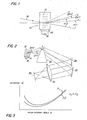
- a conventional diffraction cell 10 contains acoustic waves 12 of frequency f l produced by a transducer 14, which is in turn energized by a signal source 16.
- Watson and Korpel require different prisms for different beams. This requires spatially separate beams.
- Watson and Korpel provide spatially separate beams by using three separate acoustooptic deflectors driven by the same signal.
- a single acoustooptic deflector can be used to deflect two or more beams while the prior art uses separate deflectors for each beam.
- prism means positioned in the path of both beams which prism means magnifies the scan angles of both beams by an amount which is an inverse function of the wavelengths of the beams.
- a single prism having indexes of refraction n 1 and n 2 for the wavelengths in question and an apex angle A is positioned with the deflected light beams incident on its tang surface at approximately the same incident angle ⁇ .
- the parameters n 1 , n 2 , A and ⁇ are chosen so that the product of the wavelength and the magnification of scan angle of one beam is equal to that of the other beam.
- a single prism is used to equalize the scan angles for three light beams of different wavelength, by proper choice of n 1 , n 2 , n 3 , A and ⁇ .
- the prism means provides such separation or greatly shortens the optical path necessary for such separation. Therefore, according to another embodiment, three beams of different wavelength are passed through a single prism which equalizes the scan angle of two of the beams and contributes to the separation of the third beam from the first two. The scan angle of the third beam is equalized with the first two by further magnifying its scan angle with a second prism positioned only in the third beam.
- Acoustooptic deflectors normally function at very small scan and diffraction angles, for example, less than 1 0 in each case. However, these angles are shown much greater than this in the drawings for illustrative purposes.
- a schematic representation of light deflector apparatus constructed in accordance with the present invention, is shown.
- Diffraction cell 10 is identical to that shown in Fig. 1, described above.
- the acan angles of beams exiting from cell 10 vary in direct proportion with wavelength.
- the apparatus is optically achromatized by prism means, for example, single prism 26 positioned in the path of the deflected beams to differentially magnify and thus equalize the scan angles of the different wavelength light.
- a pair of centering mirrors 26 and 30 realign the beams so that all rays impinging upon an imaging lens 31 at any instant are parallel.
- the lens focuses the parallel beams to a point at plane 32, which point varies according to the scan angle.
- the parameters of prism 26 are selected in accordance with the present invention so that -the scan angle A a of each beam is magnified by an amount necessary to equalize the scan angles of the two beams.
- an advantage of the invention is that the prism greatly shortens the path required to separate the beams for optical elements such as centering mirrors 28 and 30. In fact, if the scan angles of the original diffracted beams overlap and emanate from the same point in cell 10, they will never separate without the prism or other optical elements.
- the angle between the path of the incident and emergent rays of a light beam passing through a prism is the angle of deviation D.
- the amount of deviation is dependent upon the index-of refraction n of the prism material for the particular wavelength, the apex angle A of the prism and the incident angle ⁇ (the angle between the incident light beam and the normal to the incident prism face). The relationship between these parameters is:
- Fig. 3 is a typical plot for two different optical wavelengths ⁇ 1 and ⁇ 2 of deviation versus incident angle. Note that as the angle of incidence is, say, decreased from a large value (moving from right to left), the angle of deviation decreases at first and then increases.
- the angle of minimum deviation D m is related to the apex angle of the prism and its index of refraction as discussed in Sears and Zemansky, University Physics, 2nd Edition, Addison-Wesley Publishing Company, page 736.
- the magnification M of the prism at any value of incident angle ⁇ is equal to the slope dD/d ⁇ .
- the change in incident angle ⁇ of a beam arriving at a prism face from an acoustooptic deflector cell as in Fig. 2 is linearly related to the change ⁇ ain the diffraction angle a of the cell.
- the scan angles ⁇ 1 , ⁇ 2 ,..., ⁇ n corresponding to light of wavelengths ⁇ 1, ⁇ 2, ... ⁇ n are directly proportional to wavelengths.
- a prism is one device wherein magnification varies inversely with wavelength. That is, the prism magnification M cam be greater for shorter optical wavelengths. In the region to the left of the point of minimum deviation in Fig. 3, the slope for the shorter wavelength ⁇ 1 -s more negative than that for the longer wavelength ⁇ 2 . Unfortunately, the relationship is not linear. However, if specific values for the parameters can be found where the relationship holds for two or more specific wavelengths, very close achromatization over small diffraction and scan angles can be effected.
- Deviation as a function of the apex angle can be computed from equation (3) for a given prism material and a fixed incident angle ⁇ .
- the chosen apex angle cannot be so large that any light beam will suffer total internal reflection within the prism.
- the relative magnification can be adjusted to the desired value by choosing the appropriate angle of incidence 0.
- Acoustooptic deflectors commonly function at very small scan and diffraction angles. For example, both angles may be less than 1°. For this reason, a single angle ⁇ is used for all wavelengths in determining.prism parameters and orientation. If the angle ⁇ varies substantially between beams, then allowance for such variance must be made, which allowance is within the skill of the art.
- FIG. 7 Another technique, which does not require changing the wavelength of any beam, is shown in Fig. 7. ' A second "trimming" prism 34 has been used to compensate for the horizontal distance between the circled points in Figure 6 by providing an additional control on the magnification for one wavelength. Essentially, this involves separating one of the three beams for individual magnification.
- M 2 cannot change because a change in the magnification of the ⁇ 2 wavelength light scan angle would effect R 12 also. Therefore, only M 3 may be adjusted.
- a trimming prism of apex angle equal to 9.5° in the path of the ⁇ 3 beam would provide correct additional magnification of one wavelength.
- Prism 26 both equalizes the scan angles of ⁇ 1 and ⁇ 2 and shortens greatly the optical path required before the beans separate enough to use prism 34.
- the invention can be used in applications requiring scanning multi-color light. It is particularly usable with discrete wavelength beams of small bandwidth such as those produced by lasers. Accordingly, it can be used in laser color television receivers, laser color printers and laser color copiers.
Applications Claiming Priority (2)
| Application Number | Priority Date | Filing Date | Title |
|---|---|---|---|
| US806205 | 1977-06-13 | ||
| US05/806,205 US4150880A (en) | 1977-06-13 | 1977-06-13 | Optical achromatization for acoustooptic deflectors |
Publications (1)
| Publication Number | Publication Date |
|---|---|
| EP0000104A1 true EP0000104A1 (fr) | 1978-12-20 |
Family
ID=25193563
Family Applications (1)
| Application Number | Title | Priority Date | Filing Date |
|---|---|---|---|
| EP78300038A Withdrawn EP0000104A1 (fr) | 1977-06-13 | 1978-06-13 | Dispositif achromatique de déflexion acoustooptique |
Country Status (3)
| Country | Link |
|---|---|
| US (1) | US4150880A (fr) |
| EP (1) | EP0000104A1 (fr) |
| JP (1) | JPS546564A (fr) |
Cited By (1)
| Publication number | Priority date | Publication date | Assignee | Title |
|---|---|---|---|---|
| EP0935150A1 (fr) * | 1998-02-09 | 1999-08-11 | LDT GmbH & Co. Laser-Display-Technologie KG | Dispositif de balayage, son utilisation et système vidéo |
Families Citing this family (9)
| Publication number | Priority date | Publication date | Assignee | Title |
|---|---|---|---|---|
| FR2507332A1 (fr) * | 1981-06-04 | 1982-12-10 | Roulot Maurice | Source lumineuse polychromatique munie d'un deviateur de rayons lumineux et d'un correcteur d'aberration chromatique |
| US4499437A (en) * | 1981-07-08 | 1985-02-12 | Eastman Kodak Company | Apparatus and method providing improved control of a laser beam |
| US4541694A (en) * | 1982-03-27 | 1985-09-17 | Rediffusion Simulation Limited | Acousto-optic scanners |
| FI872508A (fi) * | 1986-06-10 | 1987-12-11 | Kei Mori | Anordning foer aostadkommande av regnbaog. |
| JPH0338984A (ja) * | 1989-07-05 | 1991-02-20 | Pioneer Electron Corp | 投射型表示装置 |
| US5264957A (en) * | 1992-07-02 | 1993-11-23 | The United States Of America As Represented By The Secretary Of The Air Force | Electrically controlled multiple dispersion (zoom) device |
| US5463493A (en) * | 1993-01-19 | 1995-10-31 | Mvm Electronics | Acousto-optic polychromatic light modulator |
| US5796512A (en) * | 1996-02-16 | 1998-08-18 | Carnegie Mellon University | Subicron imaging system having an acousto-optic tunable filter |
| JP3718397B2 (ja) * | 2000-01-07 | 2005-11-24 | ペンタックス株式会社 | マルチビーム光学系 |
Citations (1)
| Publication number | Priority date | Publication date | Assignee | Title |
|---|---|---|---|---|
| US3524011A (en) * | 1968-03-29 | 1970-08-11 | Zenith Radio Corp | Laser color display utilizing acoustical light modulators |
-
1977
- 1977-06-13 US US05/806,205 patent/US4150880A/en not_active Expired - Lifetime
-
1978
- 1978-06-13 EP EP78300038A patent/EP0000104A1/fr not_active Withdrawn
- 1978-06-13 JP JP7142978A patent/JPS546564A/ja active Pending
Patent Citations (1)
| Publication number | Priority date | Publication date | Assignee | Title |
|---|---|---|---|---|
| US3524011A (en) * | 1968-03-29 | 1970-08-11 | Zenith Radio Corp | Laser color display utilizing acoustical light modulators |
Non-Patent Citations (1)
| Title |
|---|
| IBM TECHNICAL DISCLOSURE BULLETIN, vol. 13, nr. 9, february 1971, New York, US B.B. BROWN & S.H. ROWE " Acoustic light deflector chromatic variation compensation", pages 2634-2635 * |
Cited By (2)
| Publication number | Priority date | Publication date | Assignee | Title |
|---|---|---|---|---|
| EP0935150A1 (fr) * | 1998-02-09 | 1999-08-11 | LDT GmbH & Co. Laser-Display-Technologie KG | Dispositif de balayage, son utilisation et système vidéo |
| US6281948B1 (en) | 1998-02-09 | 2001-08-28 | Ldt Gmbh & Co. Laser-Display-Technologies Kg | Device for deflection, use thereof, and a video system |
Also Published As
| Publication number | Publication date |
|---|---|
| US4150880A (en) | 1979-04-24 |
| JPS546564A (en) | 1979-01-18 |
Similar Documents
| Publication | Publication Date | Title |
|---|---|---|
| US4435041A (en) | Chromatic aberration correction in a multiwavelength light beam deflection system | |
| US5930045A (en) | Optical apparatus which uses a virtually imaged phased array to produce chromatic dispersion | |
| US5969865A (en) | Optical apparatus which uses a virtually imaged phased array to produce chromatic dispersion | |
| Thomas | Optical spectrum analysis of large space bandwidth signals | |
| US5946128A (en) | Grating assisted acousto-optic tunable filter and method | |
| US4411492A (en) | Dispersionless refractor for use with high-power lasers | |
| US3524011A (en) | Laser color display utilizing acoustical light modulators | |
| EP0000104A1 (fr) | Dispositif achromatique de déflexion acoustooptique | |
| US4460250A (en) | Acousto-optical channelized processor | |
| DE2905630A1 (de) | Optische messeinrichtung | |
| US4856884A (en) | Dynamically matched optical filtering in a multiple telescope imaging system | |
| US4541694A (en) | Acousto-optic scanners | |
| US4776654A (en) | Scanning optical system | |
| US4027946A (en) | Acousto-optic guided-light beam device | |
| GB1580364A (en) | Acoustooptic diffraction | |
| US5002395A (en) | Interferometric acousto-optic spectrum analyzer | |
| US4808823A (en) | Thermal imagers | |
| US3540795A (en) | Achromatic compensation apparatus using polarization rotation and birefringent elements | |
| US3517200A (en) | Image conversion system | |
| US6281948B1 (en) | Device for deflection, use thereof, and a video system | |
| US2768557A (en) | Uniaxial crystal electric light valve compensated for divergent light | |
| US6765644B1 (en) | Broadband optical beam steering system and method | |
| US6744991B1 (en) | Tunable chromatic dispersion and polarization mode dispersion compensator utilizing a virtually imaged phased array | |
| US20040212806A1 (en) | High-resolution optical spectrum analyzer | |
| EP0264433B1 (fr) | Procede et dispositif d'egalisation optique de phase hf |
Legal Events
| Date | Code | Title | Description |
|---|---|---|---|
| PUAI | Public reference made under article 153(3) epc to a published international application that has entered the european phase |
Free format text: ORIGINAL CODE: 0009012 |
|
| AK | Designated contracting states |
Designated state(s): CH DE FR GB NL Kind code of ref document: A1 Designated state(s): CH DE FR GB NL |
|
| 17P | Request for examination filed | ||
| STAA | Information on the status of an ep patent application or granted ep patent |
Free format text: STATUS: THE APPLICATION IS DEEMED TO BE WITHDRAWN |
|
| 18D | Application deemed to be withdrawn |
Effective date: 19810413 |
|
| RIN1 | Information on inventor provided before grant (corrected) |
Inventor name: HOWE, DENNIS GEORGE Inventor name: BLAZEY, RICHARD NELSON Inventor name: OWENS, JAMES CARL |