TECHNICAL FIELD
-
This invention relates to acoustooptic light deflection apparatus. More particularly it relates to apparatus for deflecting two or more beams of light of different wavelength through substantially the same scan angle.
BACKGROUND ART
-
It is well known that the passage of acoustic waves through a transparent medium produces a diffraction grating by periodic variation of the index of refraction of the medium. Light directed through the medium, or cell, is diffracted through a diffraction angle a, between the undiffracted and diffracted beams, according to the following formula:
for small values of a and where.1 is the vacuum wave length of the light, f is the frequency of the acoustic wave, and v is the acoustic velocity. In acoustooptic deflectors, light is deflected or scanned through a scan angle Δα by varying the acoustic frequency f.
-
However, it can be seen that equation (1) defines a different angle a for each wavelength subjected to the same'acoustic wave. If frequency f is continuously varied through a bandwidth Δf, light beams of different wavelength will scan through different scan angles according to
-
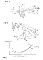
These characteristics are illustrated in Fig. 1. A conventional diffraction cell 10 contains acoustic waves 12 of frequency fl produced by a transducer 14, which is in turn energized by a signal source 16. Two beams of light having wavelengths λ1 and λ2 where λ1<λ2 travel along a path 18, enter the cell 10 and are diffracted by the acoustic wavefronts. Since the angle of diffraction is a function of optical wavelength, the light of each wavelength exits at different respective diffraction angles a 1 and a 2.
-
If the frequency of acoustic waves 12 is changed from f1 to a higher frequency f22 the diffraction angles will change in accordance with equation (2) by Δα1 Δα2, respectively, where Δα1<Δα2. Thus, it is apparent that, even if the diffraction paths of the two wavelengths could be made co-linear at one chosen frequency,such as, for example, by impinging beams of different wavelengths at different respective incident light angles, they would not remain co-linear as the frequency is varied.
-
In their article "Equalization of Acoustooptic Deflection Cells in a Laser Color TV System", Applied Optics, Vol. 9, No. 5, May 1970, W. H. Watson and A. Korpel suggest the use of an acoustooptic deflector in a three color laser television apparatus. They recognize that the dispersive characteristics of acoustooptic deflection require some form of electrical or optical compensation before three primary color images will remain in register as the acoustic frequency is varied over a bandwidth Δ f. Electrical compensation requires. different acoustic signals for each beam, thereby apparently requiring a separate acoustooptic cell for each beam. Watson and Korpel optically equalize the scan angles using separate compensating prisms to magnify the smaller blue and green scan angles to match the scan angle of the red beam.
-
The optical solution suggested by Watson and Korpel requires different prisms for different beams. This requires spatially separate beams. Watson and Korpel provide spatially separate beams by using three separate acoustooptic deflectors driven by the same signal.
DISCLOSURE OF THE INVENTION
-
It is the object of the invention to equalize the scan angles of two or more acoustooptically deflected beams using an optical means without the need of spatially separating the beams prior to the optical means. With this invention a single acoustooptic deflector can be used to deflect two or more beams while the prior art uses separate deflectors for each beam.
-
This object is accomplished by provision of prism means positioned in the path of both beams which prism means magnifies the scan angles of both beams by an amount which is an inverse function of the wavelengths of the beams.
-
According to a preferred embodiment of the invention, a single prism having indexes of refraction n1 and n2 for the wavelengths in question and an apex angle A is positioned with the deflected light beams incident on its frant surface at approximately the same incident angle θ. The parameters n1, n2, A and θ are chosen so that the product of the wavelength and the magnification of scan angle of one beam is equal to that of the other beam.
-
According to a further preferred embodiment a single prism is used to equalize the scan angles for three light beams of different wavelength, by proper choice of n1, n2, n3, A and θ.
-
Even if the light beams are eventually separated, for example, to insert other optical elements to equalize the diffraction angles, it is an advantage of the invention that the prism means provides such separation or greatly shortens the optical path necessary for such separation. Therefore, according to another embodiment, three beams of different wavelength are passed through a single prism which equalizes the scan angle of two of the beams and contributes to the separation of the third beam from the first two. The scan angle of the third beam is equalized with the first two by further magnifying its scan angle with a second prism positioned only in the third beam.
BRIEF DESCRIPTION OF THE DRAWINGS
-
In the description of the embodiments of the invention presented below, reference is made to the accompanying drawings in which:
- Fig. 1 is a schematic representation first referred to above,of two light beams of different wavelength passing through a diffraction cell, with greatly exaggerated scan and diffraction angles;
- Fig. 2 is a schematic view of an optical achromatization system according to the invention, with greatly exaggerated scan and diffraction angles;
- Fig. 3 is a plot of light deviation of a prism vs.. incident angle;
- Fig. 4 is a plot of scan angle magnification of a prism vs. prism apex angle;
- Fig. 5' is a plot of scan angle magnification of a prism vs. incident angle;
- Fig. 6 is a plot of the magnification ratios of a prism for two optical wavelengths vs.incident angle; and
- Fig. 7 is a schematic view of an optical achromatization system according to another embodiment of the invention, with greatly exaggerated scan and diffraction angles.
DETAILED DESCRIPTION OF EMBODIMENTS
-
Acoustooptic deflectors normally function at very small scan and diffraction angles, for example, less than 10 in each case. However, these angles are shown much greater than this in the drawings for illustrative purposes.
-
Referring to Fig. 2, a schematic representation of light deflector apparatus, constructed in accordance with the present invention, is shown. Diffraction cell 10 is identical to that shown in Fig. 1, described above. As in Fig. l,the acan angles of beams exiting from cell 10 vary in direct proportion with wavelength. The apparatus is optically achromatized by prism means, for example, single prism 26 positioned in the path of the deflected beams to differentially magnify and thus equalize the scan angles of the different wavelength light. A pair of centering mirrors 26 and 30 realign the beams so that all rays impinging upon an imaging lens 31 at any instant are parallel. The lens focuses the parallel beams to a point at plane 32, which point varies according to the scan angle.
-
The parameters of prism 26 are selected in accordance with the present invention so that -the scan angle A a of each beam is magnified by an amount necessary to equalize the scan angles of the two beams. In the following sections of this specification, we will discuss those parameters which affect scan angle magnification and how such parameters are used to achromatize the beams.
-
Because the prism means is placed in the path of both beams, it is not necessary to spatially separate the beams prior to entering the prism as in the prior art. However, an advantage of the invention is that the prism greatly shortens the path required to separate the beams for optical elements such as centering mirrors 28 and 30. In fact, if the scan angles of the original diffracted beams overlap and emanate from the same point in cell 10, they will never separate without the prism or other optical elements.
Scan Angle Magnification
-
The angle between the path of the incident and emergent rays of a light beam passing through a prism is the angle of deviation D. The amount of deviation is dependent upon the index-of refraction n of the prism material for the particular wavelength, the apex angle A of the prism and the incident angle θ (the angle between the incident light beam and the normal to the incident prism face). The relationship between these parameters is:
-
'From equation (3), it is seen that, for a given prism and wavelength, deviation of a light beam is a function solely of the incident angle θ. Fig. 3 is a typical plot for two different optical wavelengths λ1 and λ2 of deviation versus incident angle. Note that as the angle of incidence is, say, decreased from a large value (moving from right to left), the angle of deviation decreases at first and then increases. The angle of minimum deviation Dm is related to the apex angle of the prism and its index of refraction as discussed in Sears and Zemansky, University Physics, 2nd Edition, Addison-Wesley Publishing Company, page 736.
-
The magnification M of the prism at any value of incident angle θ is equal to the slope dD/dθ.
-
Of course, the change in incident angle Δθ of a beam arriving at a prism face from an acoustooptic deflector cell as in Fig. 2 is linearly related to the change Δain the diffraction angle a of the cell. From equation (2), the scan angles Δα
1, Δα
2,...,Δα
n corresponding to light of wavelengths λ1, λ2, ... λ
n are directly proportional to wavelengths. Mathematically, such a relationship can be expressed as follows:
-
Accordingly, if the scan angles Δα
1 (where i is any integer are multiplied by a factor M
1 which is constant over the scan angle Δα
1 and inversely proportional to the associated optical wavelength, the resulting scan angles would all be the same. Another way to express the same relationship is:
where
-
From this relationship and from Fig. 3 it can be deduced that a prism is one device wherein magnification varies inversely with wavelength. That is, the prism magnification M cam be greater for shorter optical wavelengths. In the region to the left of the point of minimum deviation in Fig. 3, the slope for the shorter wavelength λ1 -s more negative than that for the longer wavelength λ2. Unfortunately, the relationship is not linear. However, if specific values for the parameters can be found where the relationship holds for two or more specific wavelengths, very close achromatization over small diffraction and scan angles can be effected.
Selection of Apex Angle
-
Deviation as a function of the apex angle can be computed from equation (3) for a given prism material and a fixed incident angle θ. In fig. 4, magnification (dD/dθ) is plotted against apex angle for red and blue light beams (respective wavelengths of 6328A and 4416A) at an incident angle of 35°; using a prism having an index of refraction ND= 1.68893 and a dispersive index vD= 31.08.
-
For large apex angles, the absolute magnitude of the scan angle magnification increases as wavelength decreases, a desirable effect to compensate for the differences in scan angles Δα1 from acoustooptic cell 10. Thus, in order to obtain prism magnifications that are an inverse function of a wide range of optical wavelengths, we must choose relatively large prism apex angles.
-
However, as the apex angle gets larger, the critical angle will eventually be reached for the blue beam. Therefore, the chosen apex angle cannot be so large that any light beam will suffer total internal reflection within the prism.
Incidence Angle for Two Color Scan Equalization
-
Once a prism apex angle is chosen, the relative magnification can be adjusted to the desired value by choosing the appropriate angle of incidence 0. Acoustooptic deflectors commonly function at very small scan and diffraction angles. For example, both angles may be less than 1°. For this reason, a single angle θ is used for all wavelengths in determining.prism parameters and orientation. If the angle θ varies substantially between beams, then allowance for such variance must be made, which allowance is within the skill of the art.
-
Fig. 5 shows a pair of plots of magnification versus incident angle for a 40° apex angle prism having indexes of refraction n1 and n2 of 2.08537 and 2.16790 for red (λ1 = 6328A) and blue (λ2 = 4416A) respectively. It can be shown that at θ = 32°, M = constant /λ for the red (6328 A) and blue (4416 A) lines for such a prism. Thus, there is an incident angle at which the magnification will be inversely proportional to the optical wavelengths 6328 A and 4416 A for that particular prism.
-
In determining the incident angle at which the desired relationship between magnification and wavelength exists, we define Rij ≡ Mi/Mj, where i and j are integers. If only two colors λ1 and λ2 are to be deflected, achromatization will be achieved where M1λ1 = M2 λ2, or R 12 = λ2/λ1.
-
Consider the three wavelengths λ
1 = 6328 A, λ
2 = 4416 A, λ
3 = 5210 A. For the pair λ
1 and λ
2, or the Fair λ
3 and λ
2, respectively we require that:
and
-
In Figure 6, computed magnification ratios
or R
ij, are plotted vs. prism incident angle θ for a prism of the same glass as in Fig. 5 (n
3 = 2.11493) with 30° apex angle for the three optical wavelengths λ
1 = 6328 A, λ2 = 4416 A and λ
3 = 5210 A. The circled points indicate those incidence angles at which the condition of either equation (6) or (7) is fulfilled, i.e., where R
ij = λ
j/λ
i (R
12 = 0.6979and R
32 = 0.8476). Thus, if-one uses this prism at an incident angle of 29.6°, scan equalization is achieved for the two colors λ
2 = 4416 A and λ
1 = 6328 A. Similarly, achromatization of the scans of the two colors λ
3 = 5210 A and λ
2 = 4416 A is achieved by choosing θ = 28.0°. Of course, as the deflection angle a varies over a range Δα, the
incidence angle 0 will vary over a corresponding rangeΔθ, and optimum performance will result if the change in R
ij in Fig.- 6 is as small as possible over the range Δθ. Two color achromatization holds over a larger scan range A a in the case of the upper curve since the slope of that curve at θ = 28.0° is smaller than the slope of the lower curve at θ = 29.6°. Perfect two color achromatization over the entire scan range requires that the change of R
ij be zero over the range of values Δθ corresponding to the scan range of Aa.
Three Color Achromatization By Choice of Wavelengths
-
If the two circled points in Figure 6 were vertically aligned, i.e., if both equations (6) and (7) were satisfied at a single θ value, then at that value of θ, M
i = constant/λ
i, or
-
There are several ways this can be done. One way consists of choosing the third wavelength λ3 to fit the achromatization conditions of the other two wavelengths. For example, when equation (6) is satisfied, R12 = 0.6979 for λ2 = 4416 A and λ1 = 6328 A, and from Fig. 6, this is true. at θ = 29.6°. However, for the θ value 29.6°, R 32 = 0.8050 and does not satisfy equation (7) with λ2 = 5210 A.
-
We can use equation (7.) to find a value for λ3 at θ = 29.6°. Letting R32 = 0.8050 and λ2 = 4416 Å, equation (7) can be solved for λ3; and we have λ3 = λ2 R32 = 5486 A. Thus, if R32 did not change with the change in λ3, simply changing from λ3 = 5210 A to λ3 = 5486 A would accomplish three color achromatization. Of course, changing λ3 does make a slight shift in.the upper curve of Fig. 6 and thus an iterative process of solving for λ3' plotting R32, solving for a new λ3, etc., must be followed to approximate the correct value of λ3.
Three Color Achromatization By a Trimming Prism
-
Another technique, which does not require changing the wavelength of any beam, is shown in Fig. 7.
'A second "trimming"
prism 34 has been used to compensate for the horizontal distance between the circled points in Figure 6 by providing an additional control on the magnification for one wavelength. Essentially, this involves separating one of the three beams for individual magnification. A prism operating near normal incidence (θ = 0) has a magnification M
o given by
Solving for apex angle A,
-
Calculating as an example the value of A for a correcting prism needed in the example of Figure 6, we remember that at θ = 29.6° (the incident angle θ which provides scan equalization for wavelengths λ1 6328 A and λ2= 4416 A), the magnification ratio R32 must be 0.8050 to equalize the scan of a third wavelength λ3. For two color scan equalization with λ3 = 5210 A and λ2 = 44l6A it has been shown that R32 must equal 0.8476.
-
Hence, we see that we can have three color scan equalization without changing the optical wavelengths (as was required by the technique of the preceding section) at θ = 29.6° if R32 is increased from 0.8050 to 0.8476. In doing so, M2 cannot change because a change in the magnification of the λ2 wavelength light scan angle would effect R12 also. Therefore, only M3 may be adjusted. The amount of adjustment in our example is determined by multiplying the magnification ratio 0.8u50 by a factor which would bring it to 0.8476, or by 1.053. This can be accomplished by magnifying the scan angle of the λ3 beam by 1.053 by placing a "trimming" prism of magnification Mo= 1.053 in the path of that beam.
-
If the same glass is used for both prisms'26 and 34 then
-
Thus, a trimming prism of apex angle equal to 9.5° in the path of the λ3 beam would provide correct additional magnification of one wavelength.
-
This example illustrates an advantage of the invention. Prism 26 both equalizes the scan angles of λ1 and λ2 and shortens greatly the optical path required before the beans separate enough to use prism 34.
-
The invention has been described in detail with particular reference to certain preferred embodiments thereof, but it will be understood that variations and modifications can be effected within the spirit and scope of the invention. For example, additional degrees of freedom can be obtained in matching three wavelength light with the desired prism parameters if the prism is compound, for example, with two prisms of differing dispersive characteristics either cemented together or airspaced.
INDUSTRIAL APPLICATION
-
The invention can be used in applications requiring scanning multi-color light. It is particularly usable with discrete wavelength beams of small bandwidth such as those produced by lasers. Accordingly, it can be used in laser color television receivers, laser color printers and laser color copiers.