EP0000045B1 - Electrophotographic copying machine comprising a device for erasing residual electrostatic images - Google Patents
Electrophotographic copying machine comprising a device for erasing residual electrostatic images Download PDFInfo
- Publication number
- EP0000045B1 EP0000045B1 EP78100083A EP78100083A EP0000045B1 EP 0000045 B1 EP0000045 B1 EP 0000045B1 EP 78100083 A EP78100083 A EP 78100083A EP 78100083 A EP78100083 A EP 78100083A EP 0000045 B1 EP0000045 B1 EP 0000045B1
- Authority
- EP
- European Patent Office
- Prior art keywords
- radiation
- spectral
- spectral region
- maximum
- light
- Prior art date
- Legal status (The legal status is an assumption and is not a legal conclusion. Google has not performed a legal analysis and makes no representation as to the accuracy of the status listed.)
- Expired
Links
Images

Classifications
-
- G—PHYSICS
- G03—PHOTOGRAPHY; CINEMATOGRAPHY; ANALOGOUS TECHNIQUES USING WAVES OTHER THAN OPTICAL WAVES; ELECTROGRAPHY; HOLOGRAPHY
- G03G—ELECTROGRAPHY; ELECTROPHOTOGRAPHY; MAGNETOGRAPHY
- G03G21/00—Arrangements not provided for by groups G03G13/00 - G03G19/00, e.g. cleaning, elimination of residual charge
- G03G21/06—Eliminating residual charges from a reusable imaging member
- G03G21/08—Eliminating residual charges from a reusable imaging member using optical radiation
Definitions
- the invention relates to an electrophotographic copying device, as specified in the preamble of claim 1.
- a copying device is known from DE-OS 26 46 150, in which two individual light sources with radiation of the same spectral distribution are provided for quenching the charge of the electrophotographic layer.
- DE-OS Relating to the cyclical process of xerography with erasing-charge spraying-scanning-toner-sputtering-printing, the device known from DE-OS uses a light source as usual for complete erasing after printing. However, the second light source for partially erasing the charge is interposed between toner sputtering and printing.
- the carrier of the layer used is transparent to radiation and this second light source is arranged on the back of the carrier, because in this state one side of the layer is still covered with the toner of the image which has not yet been printed .
- the spectral distribution of these two light sources it is stipulated that at least 25% of the radiation intensity falls in a wavelength range in which the optical density of the image carrier is at least 50% of the highest optical density of the image carrier, here under "optical density" not the refractive index of the Layer material, but a measure of the spectral radiation absorption in the layer is to be understood.
- DE-OS 26 46 150 in addition to using a second light source for partially extinguishing the charge even before printing in the case of a radiation carrier which is necessarily permeable to radiation, is intended to reduce the symptoms of fatigue which are noticeable as ghosting (page 12, paragraph 1) do.
- a reference contained in the DE-OS to red extinguishing light (p. 22) instead of green or white extinguishing light (page 18, paragraph 3) relates to its use with organic photoconductors with absorption maxima, which are spectral with light of the wavelength range of this red light match (page 23 paragraph 2 and page 15 paragraph 1).
- Electrophotographic copying devices are known from the prior art, in which an electrostatic charge image is generated in a layer of a photoconductive material such as arsenic-selenium.
- the layer is charged by means of a corona discharge.
- An inscribed charge image is usually deleted with light of a spectral range of maximum photoconductivity generation.
- spectral range i.e. a spectral range with which the greatest increase in conductivity compared to the dark conductivity is achieved in comparison with other spectral ranges under otherwise identical radiation conditions.
- this spectral range lies in the green light range at approximately 500 nm.
- the charge image is generally written in with light of the same spectral range.
- FIG. 1 schematically shows the result to be achieved with the invention.
- the diagram shows the charging surface potential over the number of successive charges with a sequence of points 1. For comparison, the case is entered in this diagram in which the extinguishing with light of an incandescent lamp with filtering as used in the prior art has been carried out.
- sequence 2 consisting of crosses is entered. Each point or cross corresponds to a potential measurement after charging a drum, as is customary in such copying devices, on which the photoconductive layer of As-Se is located. No write exposure is involved in these rounds of episodes 1 and 2. From the diagram or from the difference between sequence 1 and sequence 2, one can clearly see this one stabilizing effect which is achieved with the measure according to the invention.
- Circles of a sequence 3 denote the potential of the photoconductive layer which is suitable for one of the revolutions of the drum, i.e. for one of the successive copying processes, in the case of write exposure with such light, which according to the known prior art - see e.g. U.S. Patent 3,511 1,649 - leads to severe potential fatigue.
- the representation is normalized to these potential values 3 with respect to the ordinate.
- the advantage described above also has the further advantage that, after a write exposure indicated with sequence 3 of the circles, subsequent cycles of a sequence 4 (again shown with circles) in which no more write exposure is provided, the same potential value occurs immediately as in episode 1 and remains the same for the other cycles.
- the point sequences 1 and 4 thus together represent a constant charging of the surface potential independent of write exposure processes, which is achieved with the measures according to the invention for all cycles in which there is no write exposure (regardless of the number of previous such cycles).
- FIG. 1 furthermore shows which potential values of the surface potential occur on the other hand if, for example, a filtered incandescent lamp is used in accordance with the known prior art.
- Sequence 5 which is marked by triangles, indicates the sequence of charges of the layer occurring from cycle to cycle, counted after the last write exposure, in the event that the measures according to the invention are not applied.
- the invention therefore provides for the light used for the extinction to be composed of two spectral ranges.
- One spectral range is approximately ⁇ 10% around a radiation wavelength at which maximum photoconductivity generation can be achieved in the photoconductive material.
- this value of the maximum 12 is 500 nm.
- the width indicated with + 10% characterizes the spectral range in which light is equivalent in terms of the photoconductivity generation in the respective material.
- the integral of the radiation energy over this range is effective in the photoconductive material for photoconductivity generation.
- the other spectral range in which the wavelength for light of the maximum of the product of photoconductivity generation and penetration depth lies.
- the penetration depth is the distance from the surface of the layer at which the intensity of the radiation incident perpendicularly to the surface has dropped to 1 / e.
- the effect of the light 13, for the wavelength of which the product of photoconductivity generation and penetration depth is maximum, corresponds physically to an amplification effect due to changed space charge conditions, which produce a higher photoconductivity for light of all wavelength ranges which are shorter-wavelength than the light of this spectral range 13.
- the light of the two spectral ranges provided according to the invention can thus be light from a single radiation source which is provided, for example, with appropriate filters.
- this dimensioning according to the invention can also be implemented with the aid of two light sources, one of which emits white light and the other light practically only of the spectral range of the maximum photoconductivity generation 11, in the case of the As Z Se 3 green light.
- the light of the area of the maximum product can therefore be part of this white light.
- the spectral range of maximum photoconductivity generation is designated with 11, with 12 indicating the wavelength of the maximum plotted on the abscissa.
- the range 11 around this wavelength value 12 is defined as ⁇ 10%. It should be pointed out that the specification ⁇ 10% is an approximate specification which is dependent on the respective photoconductive material anyway and is essentially intended to give the person skilled in the art an indication.
- the range of the wavelengths of the maximum of the product of photoconductivity generation and penetration depth is illustrated in a corresponding manner by 13. This lies around a wavelength 14.
- FIG. 2 An example of the energy ratio of the radiations of these regions to one another can be seen from the illustration in FIG. 2.
- the approximate position of the absorption curve of a photoconductive material as a function of the wavelength is plotted in the diagram in FIG. 2.
- the position of the areas provided according to the invention in relation to this absorption curve can be clearly seen from this illustration.
- the line 16 shown in broken lines in FIG. 2 indicates additional radiation, which may be present, for example, and which lies outside the spectral ranges mentioned. Spectral components of this radiation that fall into the respective spectral ranges 11 and 13 are to be included in the energy values of the ranges 11 and 13, respectively.
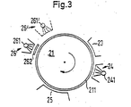
- Fig. 3 shows schematically a known copying device in which the invention is implemented.
- 21 is a drum on which the photosensitive layer 211 is located.
- a device for a corona discharge is indicated.
- 24 denotes a device for writing exposure in which there is a light source 241 for, for example, red light.
- a printing device for making the electrostatic copies is indicated.
- 26 a device is designated in which the Erfin is specifically realized.
- the light source 261 located in this device 26 can, for example using a filter 262, deliver both the light of the spectral range of maximum photoconductivity generation and the light of the spectral range of the maximum of the specified product.
- a second device 26 'with a light source 261 is included, which generates the required light of the other spectral range.
- a second device 26 'with a light source 261 is included, which generates the required light of the other spectral range.
- the light of the two spectral ranges reach the surface of the drum 21 or the layer 211 simultaneously. Rather, it is also possible to carry out the irradiation of the light of the one spectral range in time after the irradiation of the light of the other spectral range (and vice versa).
- these two exposures are carried out in succession (not separated from one another, for example by a corona charge or a copying process), namely between the printing process with the device 25 and the (re) charging of the corona. Facility 23.
- the contrast potential 5 minus 3 (FIG. 1) changes by 50% until its stabilized end value is set.
- A results in a corona current density of 13,4.10-4- to a charge potential of 700 V.
- changes m2 the contrast potential minus 4 3 (Fig. 1) by less than 3% and for setting its stabilized final value, what the desired Influence of the proposed device 26 illustrates.
- the erasure exposure according to the invention which can also be addressed as pre-exposure before the corona charge, results in an increased photosensitivity of the material of the layer for the write exposure with a light long-wave spectral range.
- "Long-wave” is to be understood as a wavelength range in which the light energy essentially corresponds to the band edge of the respective photoconductive material. For As 2 Se 3 , this is a range from approximately 550 to 650 nm. Previously, registered letters with such a long wavelength had to be ruled out in practice, as can be seen, for example, from US Pat.
Landscapes
- Health & Medical Sciences (AREA)
- Toxicology (AREA)
- Physics & Mathematics (AREA)
- General Physics & Mathematics (AREA)
- Discharging, Photosensitive Material Shape In Electrophotography (AREA)
- Photoreceptors In Electrophotography (AREA)
- Exposure Or Original Feeding In Electrophotography (AREA)
- Light Sources And Details Of Projection-Printing Devices (AREA)
Description
Die Erfindung bezieht sich auf eine elektrofotografische Kopiervorrichtung, wie sie im Oberbegriff des Patentanspruches 1 angegeben ist.The invention relates to an electrophotographic copying device, as specified in the preamble of claim 1.
Eine Kopiervorrichtung nach dem Oberbegriff ist aus der DE - OS 26 46 150 bekannt, in der zwei einzelne Lichtquellen mit Strahlung gleicher Spektralverteilung zur Löschung der Ladung der elektrofotografischen Schicht vorgesehen sind. Bezogen auf den zyklischen Prozeß der Xerografie mit Löschen-Ladungsaufsprühung-Ablichten-Toneraufstäuben-Drucken ist bei der aus der DE - OS bekannten Einrichtung die eine Lichtquelle wie üblich zum vollständigen Löschen nach dem Drucken verwendet. Die zweite Lichtquelle für ein teilweises Löschen der Aufladung ist jedoch zwischen das Toneraufstäuben und das Drucken eingefügt. Um die ganze Fläche der Schicht mit der zweiten Lichtquelle erfassen zu können, ist der verwendete Träger der Schicht strahlungsdurchlässig und diese zweite Lichtquelle auf der Rückseite des Trägers angeordnet, denn die eine Schichtseite ist in diesem Zustand noch mit dem Toner des noch nicht gedruckten Bildes bedeckt. Für die Spektralverteilung dieser beiden Lichtquellen wird dort vorgeschrieben, daß wenigstens 25% der Strahlungsintensität in einen Wellenlängenbereich fällt, in dem die optische Dichte des Bildträgers mindestens 50% der höchsten optischen Dichte des Bildträgers beträgt, wobei hier unter "optischer Dichte" nicht der Brechungsindex des Schichtmaterials, sondern ein Maß für die spektrale Strahlungs absorption in der Schicht zu verstehen ist.A copying device according to the preamble is known from DE-OS 26 46 150, in which two individual light sources with radiation of the same spectral distribution are provided for quenching the charge of the electrophotographic layer. Relating to the cyclical process of xerography with erasing-charge spraying-scanning-toner-sputtering-printing, the device known from DE-OS uses a light source as usual for complete erasing after printing. However, the second light source for partially erasing the charge is interposed between toner sputtering and printing. In order to be able to cover the entire surface of the layer with the second light source, the carrier of the layer used is transparent to radiation and this second light source is arranged on the back of the carrier, because in this state one side of the layer is still covered with the toner of the image which has not yet been printed . For the spectral distribution of these two light sources it is stipulated that at least 25% of the radiation intensity falls in a wavelength range in which the optical density of the image carrier is at least 50% of the highest optical density of the image carrier, here under "optical density" not the refractive index of the Layer material, but a measure of the spectral radiation absorption in the layer is to be understood.
Diese Maßnahme aus der DE - OS 26 46 150, zusätzlich eine zweite Lichtquelle zum teilweisen Löschen der Aufladung schon vor dem Drucken bei notwendigerweise strahlungsdurchlässigem Schichtträger zu verwenden, soll der Verringerung solcher Ermüdungserscheinungen dienen, die sich als Geisterbilder (Seite 12 Abs. 1) bemerkbar machen. Ein in der DE - OS enthaltener Hinweis auf rotes Löschlicht (S. 22), anstelle von grünem oder von weißem Löschlicht (Seite 18 Abs. 3) bezieht sich auf dessen Verwendung bei speziell in organischen Fotoleitern mit Absorptionsmaxima, die spektral mit Licht des Wellenlängenbereichs dieses Rotlichts übereinstimmen (Seite 23 Abs. 2 und Seite 15 Abs. 1).This measure from DE-OS 26 46 150, in addition to using a second light source for partially extinguishing the charge even before printing in the case of a radiation carrier which is necessarily permeable to radiation, is intended to reduce the symptoms of fatigue which are noticeable as ghosting (
Aus dem Stand der Technik sind elektrofotografische Kopiervorrichtungen bekannt, bei denen ein elektrostatisches Ladungsbild in einer Schicht aus einem fotoleitfähigen Material wie Arsen-Selen erzeugt wird. Bei diesen Kopiervorrichtungen wird eine Aufladung der Schicht mit Hilfe einer Corona-Entladung vorgenommen. Die Löschung eines eingeschrieben Ladungsbildes erfolgt üblicherweise mit Licht eines Spektralbereiches maximaler Fotoleitfähigkeitserzeugung.Electrophotographic copying devices are known from the prior art, in which an electrostatic charge image is generated in a layer of a photoconductive material such as arsenic-selenium. In these copying devices, the layer is charged by means of a corona discharge. An inscribed charge image is usually deleted with light of a spectral range of maximum photoconductivity generation.
d.h. eines Spektralbereichs, mit dem im Vergleich zuanderen Spektralbereichen unter sonst gleichen Bestrahlungsbedingungen die größte Leitfähigkeitssteigerung gegenüber der Dunkelleitfahigkeit erzielt wird.i.e. a spectral range with which the greatest increase in conductivity compared to the dark conductivity is achieved in comparison with other spectral ranges under otherwise identical radiation conditions.
Dieser Spektralbereich liegt für das beispielhaft angegebene Arsen-Selen (As2Se3) im Bereich grünen Lichts bei etwa 500 nm. Das Einschreiben des Ladungsbildes wird im allgemeinen mit Licht des gleichen Spektralbereichs vorgenommen.For the arsenic selenium (As 2 Se 3 ) given by way of example, this spectral range lies in the green light range at approximately 500 nm. The charge image is generally written in with light of the same spectral range.
Es sind auch vom Erfinder der verliegenden Erfindung vorausgegangene Untersuchungen durchgeführt worden, mit Licht des roten Spektralbereiches einzuschreiben. Mit dieser Maßnahme des Einschreibens mit Licht des roten Spektralbereichs läßt sich ein elektrostatisches Ladungsbild erreichen, das durch die übliche Corona-Aufladung nicht beseitigt, sondern regeneriert wird. Die Löschung eines derart eingeschriebenen Ladungsbildes erfolgte auch bei diesem Einschreiben wie üblich mit wie oben angegebenem grünen Licht.Investigations preceding the inventor of the present invention have also been carried out to inscribe with light of the red spectral range. With this measure of inscription with light of the red spectral range, an electrostatic charge image can be achieved, which is not removed but regenerated by the usual corona charging. The charge image inscribed in this way was also deleted in this inscription as usual with the green light indicated above.
Es hat sich gezeigt, daß bei elektrofotografischen Kopiervorrichtungen der bekannten und der oben beschrieben Art Ermüdungseffekte der Schicht auftreten. Diese Ermüdungseffekte treten insbesondere bei Fotoleitern mit feldstärkeabhängiger Beweg!ichkeitsverteilung auf, zu denen das erwähnte As2Se3 gehört. Ein solcher Ermüdungseffekt ist des weiteren z.B. auch in der DE - OS 20 37 456 für OdS beschrieben. Dort ist eine Vorbelichtung vorgesehen, deren Intensität abhängig vom festzustellenden Sättigungsgrad der Schicht, d.h. abhängig von der Anzahl der vorangegangenen Kopiervorgänge, jeweils schrittweise verringert wird.It has been found that fatigue effects of the layer occur in electrophotographic copying devices of the known and the type described above. These fatigue effects occur particularly in the case of photoconductors with field strength-dependent mobility distribution, to which the As 2 Se 3 mentioned belongs. Such a fatigue effect is also described, for example, in DE-OS 20 37 456 for OdS. A pre-exposure is provided there, the intensity of which is reduced step by step depending on the degree of saturation of the layer to be determined, ie depending on the number of previous copying processes.
Zur Beseitung dieses z.B. in der vorgenannten DE - OS beschriebenen Ermüdungseffekts ist dort angegeben, eine solche Belichtung der fotoleitenden Schioht vorzunehmen, deren Stärke vom jeweils vorliegenden Oberflächenpotential des Fotoleiters abhängig gemacht wird.To eliminate this e.g. The fatigue effect described in the aforementioned DE-OS specifies that the photoconductive layer should be exposed in such a way, the strength of which is made dependent on the surface potential of the photoconductor in each case.
Die Ermüdungserscheinung macht sich dadurch bemerkbar, daß bei mehrfach aufeinander folgendem zyklischen Aufladen der fotoleitenden Schicht mittels der Corona-Entladung eine kontinuierliche abnahme des tatsächlich erreichten Oberflächenpotentials auftritt. Dies führt zu Kontrastver- änderungen in den Kopien bei fortlaufender Benutzung der Kopiervorrichtung.The phenomenon of fatigue is noticeable in the fact that when the photoconductive layer is charged several times in succession by means of the corona discharge, there is a continuous decrease in the surface potential actually achieved. This leads to changes in the contrast in the copies when the copying device is used continuously.
Es ist Aufgabe der vorliegenden Erfindung, Maßnahmen für eine Kopiervorrichtung anzugeben, mit denen eine Stabilisierung und/oder Erhöhung des Kontrastpotentials erreicht wird, d.h. mit denen Ermüdungseffekte eliminiert werden können.It is an object of the present invention to provide measures for a copying device with which stabilization and / or increase in the contrast potential is achieved, i.e. with which fatigue effects can be eliminated.
Diese Aufgabe wird mit einer wie in Oberbegriff des Patentanspruches 1 angegebenen Vorrichtung erreicht, die erfindungsgemäß gekennzeichnet ist, wie dies im Kennzeichen des Patentanspruches 1 angegeben ist.This object is achieved with a device as specified in the preamble of claim 1, which is characterized according to the invention, as indicated in the characterizing part of claim 1.
Weitere Ausgestaltungen und Weiterbildungen der Erfindung gehen aus den Unteransprüchen hervor.Further refinements and developments of the invention emerge from the subclaims.
Die Verwendung von Licht einer Glühlampe, das einen überwiegenden Rotanteil oder gefilterte Anteile aus einem einzigen Spektralbereich zum Löschen hat, führte nach Feststellungen des Erfinders zu dem oben bereits erwähnten nachteiligen Effekt, daß von Kopie zu Kopie das Oberflächenpotential abnimmt. Die erfindungsgemäße Maßnahme einer speziellen Bemessung der Energieanteile verschiedener Spektralbereiche des zur Löschung vorgesehenen Lichtes ermöglicht es, diesen Effekt vollständig zu beseitigen. Die beigefügte Fig. 1 zeigt in einem Diagramm schematisch das mit der Erfindung zu erreichende Ergebnis. In dem Diagramm ist das Auflade-Oberflächenpotential über der Zahl der aufeinanderfolgenden Aufladungen mit einer Punktfolge 1 dargestellt. Zum Vergleich ist in dieses Diagramm der Fall eingetragen, in dem das Löschen mit Licht einer wie im Stand der Technik benutzten Glühlampe mit Filterung vorgenommen worden ist. Hierfür ist eine Folge 2, bestehend aus Kreuzen, eingetragen. Ein jeder Punkt bzw. ein jedes Kreuz entspricht einer Potentialmessung nach den Aufladen einer wie üblich in solchen Kopiervorrichtungen verwendeten Trommel, auf der sich die fotoleitende Schicht aus As-Se befindet. Bei diesen Umläufen der Folgen 1 und 2 wirkt keine Schreibbelichtung mit. Aus dem Diagramm bzw. aus dem Unterschied zwischen der Folge 1 und der Folge 2 erkennt man deutlich diesen einen Stabilisierungseffekt, der mit der erfindungsgemäßen Maßnahme erreicht wird.The use of light from an incandescent lamp, which has a predominant red component or filtered components from a single spectral range for quenching, has, according to the inventor's findings, led to the above-mentioned disadvantageous effect that the surface potential decreases from copy to copy. The measure according to the invention of a special dimensioning of the energy components of different spectral ranges of the light provided for the quenching makes it possible to completely eliminate this effect. The attached FIG. 1 schematically shows the result to be achieved with the invention. The diagram shows the charging surface potential over the number of successive charges with a sequence of points 1. For comparison, the case is entered in this diagram in which the extinguishing with light of an incandescent lamp with filtering as used in the prior art has been carried out. For this, a sequence 2 consisting of crosses is entered. Each point or cross corresponds to a potential measurement after charging a drum, as is customary in such copying devices, on which the photoconductive layer of As-Se is located. No write exposure is involved in these rounds of episodes 1 and 2. From the diagram or from the difference between sequence 1 and sequence 2, one can clearly see this one stabilizing effect which is achieved with the measure according to the invention.
Mit der Erfindung wird darüber hinaus noch ein weiterer Vorteil erreicht, nämlich ein vergrößertes Kontrastpotential, das unabhängig von den vorangegangenen Belichtungszyklen ist. Mit Kreisen einer Folge 3 ist das Potential der fotoleitfähigen Schicht bezeichnet, das sich für einen der Umläufe der Trommel, d.h. für je einen der aufeinanderfolgenden Kopiervorgänge, bei Schreibbelichtung mit einem solchen Licht ergibt, das nach bekanntem Stand der Technik - siehe z.B. US-Patent 3 511 1 649 - zu starken Potentialermüdungserscheinungen führt. Die Darstellung ist bezüglich der Ordinate auf diese Potentialwerte 3 normiert.Another advantage is achieved with the invention, namely an increased contrast potential, which is independent of the previous exposure cycles. Circles of a sequence 3 denote the potential of the photoconductive layer which is suitable for one of the revolutions of the drum, i.e. for one of the successive copying processes, in the case of write exposure with such light, which according to the known prior art - see e.g. U.S. Patent 3,511 1,649 - leads to severe potential fatigue. The representation is normalized to these potential values 3 with respect to the ordinate.
Aus dem Voranstehenden ist deutlich zu erkennen, wie mit Hilfe der erfindungsgemäßen Maßnahme der als Kontrast auswertbare Potentialunterschied deutlich erhöht wird, der sich aus der Höhe der Punktfolge 1 bzw. Kreuze 2 und der Folge 3 der Kreise ergibt. Mit dem voranstehend beschriebenen Vorteil ist aber auch der weitere Vorteil verbunden, daß sich nach einer mit Folge 3 der Kreise angedeuteten Schreibbelichtung bei darauffolgenden Zyklen einer Folge 4 (wieder mit Kreisen dargestellt), in denen keine Schreibbelichtung mehr vorgesehen ist, sich sofort der gleiche Potentialwert wie bei der Folge 1 wieder einstellt und auch für die weiteren Zyklen beibehalten bleibt. Die Punktfolgen 1 und 4 stellen somit zusammen eine von Schreibbelichtungsvorgängen unabhängig konstante Aufladung des Oberflächenpotentials dar, die mit den erfindungsgemäßen Maßnahmen für alle Zyklen, bei denen keine Schreibbelichtung erfolgt (unabhängig von der Anzahl vorausgegangener derartiger Zyklen), erreicht wird.From the foregoing it can be clearly seen how, with the aid of the measure according to the invention, the potential difference which can be evaluated as a contrast is significantly increased, which results from the height of the point sequence 1 or crosses 2 and the sequence 3 of the circles. However, the advantage described above also has the further advantage that, after a write exposure indicated with sequence 3 of the circles, subsequent cycles of a sequence 4 (again shown with circles) in which no more write exposure is provided, the same potential value occurs immediately as in episode 1 and remains the same for the other cycles. The point sequences 1 and 4 thus together represent a constant charging of the surface potential independent of write exposure processes, which is achieved with the measures according to the invention for all cycles in which there is no write exposure (regardless of the number of previous such cycles).
Das Diagramm der Fig. 1 zeigt weiterhin, welche Potentialwerte des Oberflächenpotentials sich andererseits dann einstellen, wenn nach bekanntem Stand der Technik beispielsweise mit einer gefilterten Glühlampe gearbeitet wird. Die Folge 5, die durch Dreiecke gekennzeichnet ist, gibt die von Zyklus zu Zyklus auftretende Folge der Aufladungen der Schicht, gezählt nach letzter erfolgter Schreibbelichtung, und zwar für den Fall, daß die erfindungsgemäßen Maßnahmen nicht angewendet werden, an.The diagram in FIG. 1 furthermore shows which potential values of the surface potential occur on the other hand if, for example, a filtered incandescent lamp is used in accordance with the known prior art. Sequence 5, which is marked by triangles, indicates the sequence of charges of the layer occurring from cycle to cycle, counted after the last write exposure, in the event that the measures according to the invention are not applied.
Mit wenigen Worten zusammengefaßt, ist somit bei der Erfindung vorgesehen, das zur Löschung verwendete Licht aus zwei Spektralbereichen zusammenzusetzen. Der eine Spektralbereich liegt etwa ±10% um eine Strahlungswellenlänge herum, bei der eine maximale Fotoleitfähigkeitserzeugung im fotoleitfähigen Material zu erreichen ist. Für As2Se3 liegt dieser Wert des Maximums 12 bei 500 nm. Die mit +10% angegebene Breite kennzeichnet den Spektralbereich, in dem Licht bezüglich der Fotoleitfähigkeitserzeugng im jeweiligen Material gleichwertig ist. Das Integral der Strahlungsenergie über diesen Bereich ist in dem fotoleitfähigen Material zur Fotoleitfähigkeitserzeugung wirksam. Entsprechendes gilt für den anderen Spektralbereich, in dem die Wellenlänge für Licht des Maximums des Produktes aus Fotoleitfähigkeitserzeugung und Eindringtiefe liegt.Summarized in a few words, the invention therefore provides for the light used for the extinction to be composed of two spectral ranges. One spectral range is approximately ± 10% around a radiation wavelength at which maximum photoconductivity generation can be achieved in the photoconductive material. For As 2 Se 3 , this value of the maximum 12 is 500 nm. The width indicated with + 10% characterizes the spectral range in which light is equivalent in terms of the photoconductivity generation in the respective material. The integral of the radiation energy over this range is effective in the photoconductive material for photoconductivity generation. The same applies to the other spectral range, in which the wavelength for light of the maximum of the product of photoconductivity generation and penetration depth lies.
Die Eindringtiefe ist der Abstand von der Oberfläche der Schicht in dem die Intensität senkrecht auf die Oberfläche einfallenden Strahlung auf 1/e abgefallen ist. Die Wirkung des Lichtes 13, für dessen Wellenlänge das Produkt aus Fotoleitfähigkeitserzeugung und Eindringtiefe maximal ist, entspricht physikalisch einem Verstärkungseffekt durch geänderte Raumladungsverhältnisse, die eine höhere Fotoleitfähigkeit für Licht aller Wellenlängenbereiche erzeugen, die kurzwelliger als das Licht dieses Spektralbereiches 13 sind.The penetration depth is the distance from the surface of the layer at which the intensity of the radiation incident perpendicularly to the surface has dropped to 1 / e. The effect of the
In diesem Zusammenhang ist zu erwähnen, daß außer dem Licht dieser beiden angegebenen Spektralbereiche weiteres Licht nur mit einer Gesamtenergie eingestrahlt werden darf, die 10% der Gesamtstrahlungsenergie des an erster Stelle genannten Spektralbereiches (maximaler Fotoleitfähigkeitserzeugung) 11 nicht übersteigt. Das erfindungsgemäß vorgesehene Licht der beiden Spektralbereiche kann damit Licht einer einzigen Strahlungsquelle sein, die z.B. mit entsprechenden Filtern versehen ist. Diese erfindungsgemäße Bemessung kann aber auch mit Hilfe zweier Lichtquellen realisiert werden, von denen die eine weißes Licht und die andere Licht praktisch nur des Spektralbereiches der maximalen Fotoleitfähigkeitserzeugung 11, im Falle des AsZSe3 grünes Licht, abgibt. Dabei kann also das Licht des Bereiches des maximalen Produktes Anteil dieses weißen Lichtes sein.In this context, it should be mentioned that in addition to the light of these two spectral ranges specified, further light may only be radiated in with a total energy which does not exceed 10% of the total radiation energy of the spectral range mentioned in the first place (maximum photoconductivity generation) 11. The light of the two spectral ranges provided according to the invention can thus be light from a single radiation source which is provided, for example, with appropriate filters. However, this dimensioning according to the invention can also be implemented with the aid of two light sources, one of which emits white light and the other light practically only of the spectral range of the maximum photoconductivity generation 11, in the case of the As Z Se 3 green light. The light of the area of the maximum product can therefore be part of this white light.
Die Fig. 2 soll noch ergänzend die Spektralbereiche und die Strahlungsenergien dieser Bereiche im Verhältnis zueinander und bezüglich der Absorptionskurve des Materials des Fotoleiters verdeutlichen. Mit 11 ist der Spektralbereich maximaler Fotoleitfähigkeitserzeugung bezeichnet, wobei mit 12 die auf der Abszisse aufgetragene Wellenlänge des Maximums angegeben ist. Mit ±10% ist der Bereich 11 um diesen Wellenlängenwert 12 herum definiert. Es sei darauf hingewiesen, daß die Angabe ±10% eine ungefähre Angabe ist, die ohnehin vom jeweiligen fotoleitfähigen Material abhängig ist und dem Fachmann im wesentlichen einen Hinweis geben soll. Mit 13 ist in entsprechender Weise der Bereich der Wellenlängen des Maximums des Produktes aus Fotoleitfähigkeitserzeugung und Eindringtiefe verdeutlicht. Dieser liegt um eine Wellenlänge 14 herum. Aus der Darstellung der Fig. 2 ist ein Beispiel für das Energieverhältnis der Strahlungen dieser Bereiche zueinander ersichtlich. Mit 15 ist in das Schaubild der Fig. 2 die ungefähre Lage der Absorptionskurve eines fotoleitenden Materials in Abhängigkeit von der Wellenlänge aufgetragen. Aus dieser Darstellung ist die Lage der erfindungsgemäß vorgesehenen Bereiche in bezug auf diese Absorptionskurve gut ersichtlich.2 is intended to additionally illustrate the spectral ranges and the radiation energies of these ranges in relation to one another and with respect to the absorption curve of the material of the photoconductor. The spectral range of maximum photoconductivity generation is designated with 11, with 12 indicating the wavelength of the maximum plotted on the abscissa. The range 11 around this
Die gestrichelt in Fig. 2 eingetragene Linie 16 weist auf zusätzliche Strahlung hin, die beispielsweise zusätzlich vorhanden sein kann und die außerhalb der erwähnten Spektralbereiche liegt. Spektrale Anteile dieser Strahlung, die in die jeweiligen Spektralbereiche 11 und 13 hereinfallen, sind in die Energiewerte der Bereiche 11 bzw. 13 einzurechnen.The line 16 shown in broken lines in FIG. 2 indicates additional radiation, which may be present, for example, and which lies outside the spectral ranges mentioned. Spectral components of this radiation that fall into the respective spectral ranges 11 and 13 are to be included in the energy values of the
Fig. 3 zeigt schematisch eine an sich bekannte Kopiervorrichtung, in der die Erfindung realisiert ist. Mit 21 ist eine Trommel bezeichnet, auf der sich die fotoempfindliche Schichte 211 befindet. Mit 23 ist eine Einrichtung für eine Corona-Entladung angedeutet. Mit 24 ist eine Einrichtung zur Schreibbelichtung bezeichnet, in der sich eine Lichtquelle 241 für beispielsweise rotes Licht befindet. Mit 25 ist eine Druckeinrichtung für das Herstellen der elektrostatischen Kopien angedeutet. Mit 26 ist eine Einrichtung bezeichnet, in der speziell die Erfinrealisiert ist. Die in dieser Einrichtung 26 befindliche Lichtquelle 261 kann beispielsweise unter Anwendung eines Filters 262 sowohl das Licht des Spektralbereiches maximaler Fotoleitfähigkeitserzeugung als auch das Licht des Spektralbereiches des Maximums des angegebenen Produktes liefern.Fig. 3 shows schematically a known copying device in which the invention is implemented. 21 is a drum on which the
Die Fig. 3 enthält eine spezielle Ausgestaltung der Erfindung, bei der außer einer ersten Einrichtung 26 mit einer Lichtquelle 261 für nur den einen Spektralbereich eine zweite Einrichtung 26' mit einer Lichtquelle 261 enthalten ist, die das erforderliche Licht des anderen Spektralbereiches erzeugt. Für die Erfindung ist es nämlich nicht zwingend erforderlich, daß das Licht der beiden Spektralbereiche gleichzeitig auf die Oberfläche der Trommel 21 bzw. in die Schicht 211 gelangt. Vielmehr ist es auch möglich, die Einstrahlung des Lichtes des einen Spektralbereiches zeitlich nach der Einstrahlung des Lichtes des anderen Spektralbereiches (und umgekehrt) durchzuführen. Es braucht nicht besonders darauf hingewiesen zu werden, daß diese beiden Belichtungen aufeinanderfolgend (nicht z.B. durch eine Corona-Aufladung oder einen Kopiervorgang voneinander getrennt) vorgenommen werden, und zwar zwischen dem Druckvorgang mit der Einrichtung 25 und der (Wieder-)Aufladung der Corona-Einrichtung 23.3 contains a special embodiment of the invention, in which, in addition to a
Nachfolgend werden noch einige Zahlenbeispiele zur Erfindung angegeben, die den Einfluß der Lichtenergieanteile 1(11) und !(13) auf die Stabilisierung des Kontrastpotentials bei Verwendung von As2Se3 als Fotoleiter zeigen:


Dann ändert sich das Kontrastpotential 5 minus 3 (Fig. 1) um 50% bis zur Einstellung seins stabilisierten Endwertes.

Durch die erfindungsgemäße Löschbelichtung, die auch als Vorbelichtung vor der Corona-Aufladung anzusprechen ist, erreicht man eine gesteigerte Fotoempfindlichkeit des Materials der Schicht für die Schreibbelichtung mit einem Licht langwelligen Spektralbereiches. Dabei ist unter "langwellig" ein Wellenlängenbereich zu verstehen, bei dem die Lichtenergie der Bandkante des jeweiligen fotoleitenden Materials im wesentlichen entspricht. Für As2Se3 ist dies ein Bereich von etwa 550 bis 650 nm. Einschreiben mit derartig langer Wellenlänge war bisher nach der Praxis auszuschließen, wie dies z.B. aus der US-PS 3 511 649 hervorgeht.The erasure exposure according to the invention, which can also be addressed as pre-exposure before the corona charge, results in an increased photosensitivity of the material of the layer for the write exposure with a light long-wave spectral range. "Long-wave" is to be understood as a wavelength range in which the light energy essentially corresponds to the band edge of the respective photoconductive material. For As 2 Se 3 , this is a range from approximately 550 to 650 nm. Previously, registered letters with such a long wavelength had to be ruled out in practice, as can be seen, for example, from US Pat.
Claims (4)
Applications Claiming Priority (2)
| Application Number | Priority Date | Filing Date | Title |
|---|---|---|---|
| DE2726805 | 1977-06-14 | ||
| DE2726805A DE2726805C3 (en) | 1977-06-14 | 1977-06-14 | Electrophotographic copier with a device for erasing an electrostatic charge image |
Publications (2)
| Publication Number | Publication Date |
|---|---|
| EP0000045A1 EP0000045A1 (en) | 1978-12-20 |
| EP0000045B1 true EP0000045B1 (en) | 1981-10-21 |
Family
ID=6011507
Family Applications (1)
| Application Number | Title | Priority Date | Filing Date |
|---|---|---|---|
| EP78100083A Expired EP0000045B1 (en) | 1977-06-14 | 1978-06-02 | Electrophotographic copying machine comprising a device for erasing residual electrostatic images |
Country Status (7)
| Country | Link |
|---|---|
| US (1) | US4170413A (en) |
| EP (1) | EP0000045B1 (en) |
| JP (1) | JPS547347A (en) |
| AT (1) | AT359827B (en) |
| CH (1) | CH622628A5 (en) |
| DE (1) | DE2726805C3 (en) |
| IT (1) | IT1096641B (en) |
Families Citing this family (18)
| Publication number | Priority date | Publication date | Assignee | Title |
|---|---|---|---|---|
| JPS6027026B2 (en) * | 1977-06-17 | 1985-06-26 | キヤノン株式会社 | Electrophotographic method and apparatus |
| JPS5557875A (en) * | 1978-06-24 | 1980-04-30 | Mita Ind Co Ltd | Transfer type electrostatic copying machine |
| JPS55101981A (en) * | 1979-01-31 | 1980-08-04 | Ricoh Co Ltd | Electrophotographic copying method |
| JPS5624383A (en) * | 1979-08-02 | 1981-03-07 | Minolta Camera Co Ltd | Light erasing device in transfer type copying machine |
| JPS57212458A (en) * | 1981-06-24 | 1982-12-27 | Ricoh Co Ltd | Electrophotographic copying method |
| JPS587649A (en) * | 1981-07-08 | 1983-01-17 | Ricoh Co Ltd | Electrophographic copying method and its apparatus |
| JPS58114082A (en) * | 1981-12-28 | 1983-07-07 | Ricoh Co Ltd | Electrophotographic copying method |
| JPS58137873A (en) * | 1982-02-10 | 1983-08-16 | Ricoh Co Ltd | Photoreceptor destaticizing method |
| JPS6014255A (en) * | 1983-07-05 | 1985-01-24 | Toshiba Corp | Electrophotographic device |
| JPS6014254A (en) * | 1983-07-05 | 1985-01-24 | Toshiba Corp | Electrophotographic device |
| JPS6082669U (en) * | 1983-11-10 | 1985-06-07 | 株式会社リコー | Photoreceptor optical static eliminator |
| JPS6197683A (en) * | 1984-10-17 | 1986-05-16 | Sharp Corp | Method for stabilizing charged potential of electrophotographic sensitive body |
| DE3536836A1 (en) * | 1984-10-17 | 1986-04-17 | Sharp K.K., Osaka | UNLOADING DEVICE FOR A COPIER |
| JPS6197667A (en) * | 1984-10-17 | 1986-05-16 | Sharp Corp | Method for stabilizing charged potential of electrophotographic sensitive body |
| JPS6197681A (en) * | 1984-10-17 | 1986-05-16 | Sharp Corp | Method for preventing optical fatigue of electrophotographic sensitive body |
| JPS6197668A (en) * | 1984-10-17 | 1986-05-16 | Sharp Corp | Device for stabilizing charged potential of electrophotographic sensitive body |
| DE3901496A1 (en) * | 1988-01-21 | 1989-08-03 | Fuji Electric Co Ltd | Electrophotographic printer |
| US5606398A (en) * | 1995-04-28 | 1997-02-25 | Minnesota Mining And Manufacturing Company | Reduction of residual potential and ghosting in a photoconductor |
Family Cites Families (9)
| Publication number | Priority date | Publication date | Assignee | Title |
|---|---|---|---|---|
| US3481669A (en) * | 1965-03-01 | 1969-12-02 | Xerox Corp | Photo-charging of xerographic plates |
| US3666364A (en) * | 1965-12-01 | 1972-05-30 | Canon Kk | Electrophotographic apparatus |
| US3511649A (en) * | 1966-05-02 | 1970-05-12 | Xerox Corp | Process of reducing fatigue in photoconductive glasses |
| US3615395A (en) * | 1966-09-28 | 1971-10-26 | Canon Camera Co | Electrostatic and electrophotographic variable contrast image-forming methods |
| JPS494337B1 (en) * | 1969-07-28 | 1974-01-31 | ||
| JPS5025233A (en) * | 1972-09-20 | 1975-03-17 | ||
| US3930853A (en) * | 1973-12-06 | 1976-01-06 | Xerox Corporation | Accelerating aging method for selenium-arsenic photoconductors |
| US3963488A (en) * | 1974-09-03 | 1976-06-15 | Gaf Corporation | Contrast of electrostatic latent images with a light flooding step |
| US4035750A (en) * | 1975-10-14 | 1977-07-12 | Eastman Kodak Company | Electrophotographic apparatus having improved photoconductor regenerative structure and procedure |
-
1977
- 1977-06-14 DE DE2726805A patent/DE2726805C3/en not_active Expired
- 1977-12-15 CH CH1547477A patent/CH622628A5/de not_active IP Right Cessation
-
1978
- 1978-06-02 EP EP78100083A patent/EP0000045B1/en not_active Expired
- 1978-06-05 AT AT408778A patent/AT359827B/en not_active IP Right Cessation
- 1978-06-08 US US05/913,700 patent/US4170413A/en not_active Expired - Lifetime
- 1978-06-12 IT IT24439/78A patent/IT1096641B/en active
- 1978-06-14 JP JP7201578A patent/JPS547347A/en active Granted
Also Published As
| Publication number | Publication date |
|---|---|
| IT7824439A0 (en) | 1978-06-12 |
| US4170413A (en) | 1979-10-09 |
| JPS547347A (en) | 1979-01-20 |
| EP0000045A1 (en) | 1978-12-20 |
| DE2726805C3 (en) | 1981-01-22 |
| ATA408778A (en) | 1980-04-15 |
| AT359827B (en) | 1980-12-10 |
| DE2726805A1 (en) | 1978-12-21 |
| DE2726805B2 (en) | 1980-05-08 |
| IT1096641B (en) | 1985-08-26 |
| CH622628A5 (en) | 1981-04-15 |
| JPH0514277B2 (en) | 1993-02-24 |
Similar Documents
| Publication | Publication Date | Title |
|---|---|---|
| EP0000045B1 (en) | Electrophotographic copying machine comprising a device for erasing residual electrostatic images | |
| DE2646150C2 (en) | Electrophotographic copier with erasing device | |
| DE3530733C2 (en) | ||
| DE3020657A1 (en) | ELECTROPHOTOGRAPHIC PHOTO LADDER | |
| DE1797549C3 (en) | Process for producing a charge image on an insulating surface using an electrophotographic recording material and an electrophotographic device for carrying out the process | |
| DE3401992A1 (en) | ELECTROPHOTOGRAPHIC COPIER AND METHOD | |
| DE1910749C3 (en) | Method and apparatus for producing a screened landing image Rank Xerox Ltd, London | |
| DE2826583A1 (en) | METHOD AND DEVICE FOR ELECTROPHOTOGRAPHIC IMAGE GENERATION | |
| DE3036731A1 (en) | ELECTROPHOTOGRAPHIC DEVICE | |
| DE3536836A1 (en) | UNLOADING DEVICE FOR A COPIER | |
| DE1797577C3 (en) | Electrophotographic process | |
| DE1472926B2 (en) | Electrophotographic recording material and electrophotographic process | |
| DE3424783A1 (en) | ELECTROPHOTOGRAPHIC DEVICE | |
| DE2742891C2 (en) | Electrophotographic process with uniform pre-exposure for the formation of charge images | |
| DE2825276A1 (en) | PROCESS FOR THE FORMATION OF A LATENT, ELECTROSTATOGRAPHICALLY EVALUABLE IMAGE AND ELECTROSTATOGRAPHIC RECORDING MATERIAL | |
| DE2811056C2 (en) | Process for generating a charge image on an insulating recording material | |
| DE2759968C2 (en) | Electrophotographic process for forming an electrostatic latent image | |
| DE1572377B2 (en) | METHOD AND DEVICE FOR UNIFORM GRIDED SUPPORTS OF A PHOTOLOCULATIVE LAYER | |
| DE1205828B (en) | Method of controlling contrast in the electrophotographic production of images | |
| DE3248363A1 (en) | ELECTROPHOTOGRAPHIC PLAYBACK METHOD | |
| DE2635731C2 (en) | Device for an electrophotographic process | |
| DE2657912A1 (en) | IMAGE GENERATION PROCESS | |
| DE2347422C3 (en) | Electrophotographic recorder | |
| DE2028641A1 (en) | Electrophotographic photosensitive body and electrophotographic process using this body | |
| DE2730051C2 (en) | Electrophotographic process |
Legal Events
| Date | Code | Title | Description |
|---|---|---|---|
| PUAI | Public reference made under article 153(3) epc to a published international application that has entered the european phase |
Free format text: ORIGINAL CODE: 0009012 |
|
| AK | Designated contracting states |
Kind code of ref document: A1 Designated state(s): BE GB NL |
|
| 17P | Request for examination filed | ||
| GRAA | (expected) grant |
Free format text: ORIGINAL CODE: 0009210 |
|
| AK | Designated contracting states |
Kind code of ref document: B1 Designated state(s): BE GB NL |
|
| PG25 | Lapsed in a contracting state [announced via postgrant information from national office to epo] |
Ref country code: BE Effective date: 19820602 |
|
| PG25 | Lapsed in a contracting state [announced via postgrant information from national office to epo] |
Ref country code: NL Effective date: 19830101 |
|
| NLV4 | Nl: lapsed or anulled due to non-payment of the annual fee | ||
| REG | Reference to a national code |
Ref country code: GB Ref legal event code: 732E |
|
| PGFP | Annual fee paid to national office [announced via postgrant information from national office to epo] |
Ref country code: GB Payment date: 19970326 Year of fee payment: 20 |
|
| PG25 | Lapsed in a contracting state [announced via postgrant information from national office to epo] |
Ref country code: GB Free format text: LAPSE BECAUSE OF EXPIRATION OF PROTECTION Effective date: 19980601 |
|
| REG | Reference to a national code |
Ref country code: GB Ref legal event code: PE20 Effective date: 19980601 |
|
| PLBE | No opposition filed within time limit |
Free format text: ORIGINAL CODE: 0009261 |
|
| STAA | Information on the status of an ep patent application or granted ep patent |
Free format text: STATUS: NO OPPOSITION FILED WITHIN TIME LIMIT |