DE69936060T2 - Method and apparatus for an improved interface between computer components - Google Patents
Method and apparatus for an improved interface between computer components Download PDFInfo
- Publication number
- DE69936060T2 DE69936060T2 DE69936060T DE69936060T DE69936060T2 DE 69936060 T2 DE69936060 T2 DE 69936060T2 DE 69936060 T DE69936060 T DE 69936060T DE 69936060 T DE69936060 T DE 69936060T DE 69936060 T2 DE69936060 T2 DE 69936060T2
- Authority
- DE
- Germany
- Prior art keywords
- interface
- hub
- data
- transaction
- packets
- Prior art date
- Legal status (The legal status is an assumption and is not a legal conclusion. Google has not performed a legal analysis and makes no representation as to the accuracy of the status listed.)
- Expired - Lifetime
Links
Classifications
-
- G—PHYSICS
- G06—COMPUTING; CALCULATING OR COUNTING
- G06F—ELECTRIC DIGITAL DATA PROCESSING
- G06F13/00—Interconnection of, or transfer of information or other signals between, memories, input/output devices or central processing units
-
- G—PHYSICS
- G06—COMPUTING; CALCULATING OR COUNTING
- G06F—ELECTRIC DIGITAL DATA PROCESSING
- G06F13/00—Interconnection of, or transfer of information or other signals between, memories, input/output devices or central processing units
- G06F13/38—Information transfer, e.g. on bus
- G06F13/42—Bus transfer protocol, e.g. handshake; Synchronisation
- G06F13/4204—Bus transfer protocol, e.g. handshake; Synchronisation on a parallel bus
- G06F13/4208—Bus transfer protocol, e.g. handshake; Synchronisation on a parallel bus being a system bus, e.g. VME bus, Futurebus, Multibus
Landscapes
- Engineering & Computer Science (AREA)
- Theoretical Computer Science (AREA)
- Physics & Mathematics (AREA)
- General Engineering & Computer Science (AREA)
- General Physics & Mathematics (AREA)
- Data Exchanges In Wide-Area Networks (AREA)
- Information Transfer Systems (AREA)
Description
GEBIET DER ERFINDUNGFIELD OF THE INVENTION
Die vorliegende Erfindung betrifft das Gebiet der Computersysteme und im Besonderen das Gebiet der Bereitstellung einer verbesserten Schnittstelle zwischen Computerkomponenten.The The present invention relates to the field of computer systems and in particular, the field of providing an improved interface between computer components.
STAND DER TECHNIKSTATE OF THE ART
Moderne
Computersysteme weisen Zentraleinheiten (CPU
Wie
dies zum Beispiel ferner in
Darüber hinaus
können
auch externe Busse (z.B. ein PCI-Bus (Peripheral Component Interconnect-Bus)
Das
U.S. Patent
Folglich wird eine verbesserte Schnittstelle zwischen peripheren Komponenten und Prozessor/Speicher-Subsystemen benötigt.consequently becomes an improved interface between peripheral components and processor / memory subsystems.
ZUSAMMENFASSUNG DER ERFINDUNGSUMMARY OF THE INVENTION
Vorgesehen ist gemäß der vorliegenden Erfindung eine Schnittstelle gemäß dem gegenständlichen Anspruch 1.Intended is in accordance with the present Invention an interface according to the subject claim 1.
Weitere Ausführungsbeispiele der vorliegenden Erfindung sind in den Unteransprüchen enthalten.Further embodiments The present invention is contained in the subclaims.
Vorgesehen ist gemäß der vorliegenden Erfindung somit eine Schnittstelle für eine Datenübertragung zwischen getrennten Hubs in einem Computersystem, mit einem Datensignalpfad zur Datenübertragung zwischen Hubs in Paketen über Split-Transaktionen. In einem Ausführungsbeispiel werden die Daten in einem quellensynchronen Modus übertragen. In einem Ausführungsbeispiel weisen die Pakete zur Datenübermittlung ferner bei Bedarf ein Anforderungspaket und ein Vollzugspaket auf. In einem Ausführungsbeispiel weisen die Pakete ferner Transaktionsdeskriptoren auf.Intended is in accordance with the present Invention thus an interface for a data transfer between separate hubs in a computer system, with a data signal path for data transmission between hubs in packets over Split transactions. In one embodiment, the data becomes transmitted in a source synchronous mode. In one embodiment assign the packets for data transmission and if required, a request packet and a completion package. In one embodiment the packets further comprise transaction descriptors.
KURZE BESCHREIBUNG DER ZEICHNUNGENBRIEF DESCRIPTION OF THE DRAWINGS
Die vorliegende Erfindung ist in den Abbildungen der beigefügten Zeichnungen beispielhaft und ohne einzuschränken veranschaulicht, wobei ähnliche Elemente in den Abbildungen mit den gleichen Bezugszeichen bezeichnet sind. Es zeigen:The The present invention is illustrated in the drawings of the accompanying drawings exemplary and without limitation illustrates, with similar Elements in the figures are denoted by the same reference numerals are. Show it:
GENAUE BESCHREIBUNGPRECISE DESCRIPTION
Beschrieben wird eine verbesserte Schnittstelle zwischen Computerkomponenten. Die Schnittstelle kann hierin als ein Hub-Link bezeichnet werden. Der Hub-Link ist eine Schnittstelle zur Verbindung von Bausteinen einer Kernlogik über eine Schnittstelle mit schmaler und hoher Bandbreite.described will be an improved interface between computer components. The interface may be referred to herein as a hub link. The hub link is an interface for connecting blocks a kernel logic about an interface with narrow and high bandwidth.
Wie
dies in der Abbildung aus
Im
Besonderen veranschaulicht die Abbildung aus
Wie
dies in der Abbildung aus
Der
E/A-Hub
Durch
den Einsatz eines Hub-Link zur Zwischenverbindung des Memory Controller
Hub
Zur Bereitstellung der verbesserten Schnittstelle weist der Hub-Link ein oder mehrere einzigartige Merkmale auf. In einem Ausführungsbeispiel werden Transaktionen über den Hub-Link unter Verwendung eines Split-Transaktionsprotokolls auf Paketbasis übertragen. Zum Beispiel wird ein Anforderungspaket eingesetzt, um eine Transaktion zu beginnen, und wobei ein separates Vollzugspaket in der Folge eingesetzt werden kann, um eine Transaktion zu beenden, sofern dies erforderlich ist.to The hub link provides the improved interface one or more unique features. In one embodiment Transactions are over the hub link using a split transaction log transmitted on a packet basis. For example, a request packet is used to make a transaction to start, and being a separate enforcement package in the episode can be used to terminate a transaction, if so is required.
Die
Abbildung aus
Zwischen
dem Zeitpunkt der Übertragung
eines Anforderungspakets und eines entsprechenden Vollzugspakets über den
Hub-Link können
separate, nicht im Verhältnis
zueinander stehende Pakete gemäß vorbestimmter
Regeln für
die Reihenfolge über
den Hub-Link übertragen
werden, wie dies nachstehend im Text näher beschrieben wird. Für den Fall
einer Leseanforderung von einem Peripheriegerät in den Speicher kann die
Bereitstellung der angeforderten Daten zum Beispiel mehrere Taktzyklen
in Anspruch nehmen, bis die Daten für die Rückführung in einem Vollzugspaket
bereit stehen. Während
dem Zeitraum, der benötigt wird,
um die angeforderten Daten zu erhalten, können separate, nicht im Verhältnis zueinander
stehende Vollzugs- und/oder Anforderungspakete, die in einer Warteschlange/Pipe
des Memory Controller Hub
Wie
dies in der Abbildung aus
In einem Ausführungsbeispiel verwendet der Hub-Link darüber hinaus Transaktionsdeskriptoren, um den Hub-Link-Verkehr zu leiten sowie um die Attribute einer Transaktion zu identifizieren. Zum Beispiel können die Deskriptoren eingesetzt werden, um eine Transaktion als isochron oder asynchron zu definieren, die als Folge dessen gemäß einem vordefinierten Protokoll behandelt werden kann.In an embodiment the hub link uses it In addition, transaction descriptors to direct hub-link traffic and to identify the attributes of a transaction. To the Example, the Descriptors are used to make a transaction as isochronous or asynchronously defined as a result of a predefined protocol can be handled.
In einem Ausführungsbeispiel wird ferner die Bandbreite der Schnittstelle teilweise dadurch erhöht, dass die Datenpakete über einen quellensynchronen Taktmodus übertragen werden. In einem Ausführungsbeispiel stellt der Hub-Link ferner die erhöhte Bandbreite trotz einer schmalen Verbindung bereit (z.B. weniger Pins/Anschlussflächen).In an embodiment Furthermore, the bandwidth of the interface is partially increased by the fact that the data packets over a source synchronous clock mode are transmitted. In one embodiment In addition, the hub link provides the increased bandwidth despite one narrow connection ready (e.g., fewer pins / pads).
In alternativen Ausführungsbeispielen kann ein Hub-Link jedoch auch mit weniger als allen vorstehend beschriebenen eindeutigen Merkmalen implementiert werden, ohne dabei von dem Umfang der vorliegenden Erfindung abzuweichen. Ferner kann der Hub-Link auch verwendet werden, um Brücken miteinander zu verbinden und/oder die Komponenten in einem Chipsatz oder außerhalb eines Chipsatzes, ohne dabei vom Umfang der vorliegenden Erfindung abzuweichen.In alternative embodiments however, a hub link may also handle less than all of the above unique features are implemented without going by the scope to depart from the present invention. Furthermore, the hub link also used to build bridges connect to each other and / or the components in a chipset or outside a chipset, without departing from the scope of the present invention departing.
TRANSAKTIONS-, PROTOKOLL- UND PHYSIKALISCHE SCHICHTENTRANSACTION, PROTOCOL AND PHYSICAL LAYERS
Zur deutlicheren Veranschaulichung wird der Hub-Link hierein in drei Abschnitten beschrieben: einer Transaktionsschicht, einer Protokollschicht und einer physikalischen Schicht. Die Unterscheidungen zwischen den Schichten dienen jedoch einem veranschaulichenden Zweck und haben keine einschränkende Funktion, und somit wird dadurch kein spezielles bevorzugtes Ausführungsbeispiel impliziert.to For a clearer illustration, the hub link will be in three Sections: a transaction layer, a protocol layer and a physical layer. The distinctions between the However, layers serve an illustrative purpose and have no restrictive Function, and thus does not become a special preferred embodiment implied.
TRANSAKTIONSSCHICHTTRANSACTION LAYER
In einem Ausführungsbeispiel des Hub-Link unterstützt die Transaktionsschicht das Routing bzw. Leiten separater Transaktionen, die über den Hub-Link übertragen werden (wobei sie ein oder mehrere Pakete aufweisen können). In einem Ausführungsbeispiel erzeugt die Transaktionsschicht des Hub-Link zum Beispiel Transaktionsdeskriptoren, die in den Anforderungs- und Datenpaketen enthalten sind. Die Transaktionsdeskriptoren können zur Unterstützung der Arbitrierung zwischen Warteschlangen in einem Hub-Agenten (z.B. MCH) eingesetzt werden und/oder zur Erleichterung des Routing von Anforderungen und Datenpaketen durch den Hub-Link.In an embodiment supported by the hub link the transaction layer routing separate transactions, the above transmit the hub link (they may have one or more packets). In an embodiment For example, the transaction layer of the hub link generates transaction descriptors. which are contained in the request and data packets. The transaction descriptors can for support arbitration between queues in a hub agent (e.g., MCH) be used and / or to facilitate the routing of requirements and data packets through the hub link.
In einem Ausführungsbeispiel unterstützen zum Beispiel die Transaktionsdeskriptoren das Leiten von Vollzugspaketen zurück zu dem die Anforderung einleitenden Agenten auf der Basis der ursprünglich bereitgestellten (in einem Anforderungspaket) Routing-Informationen. Die Transaktionsdeskriptoren unterstützen ferner die Reduzierung oder möglicherweise Minimierung der Paketdecodierungslogik in den Hub-Agenten.In an embodiment support for example, the transaction descriptors directing completion packages back to the request-initiating agent based on the originally provided (in a request packet) routing information. The transaction descriptors support further the reduction or possibly Minimizing the packet decode logic in the Hub Agent.
In alternativen Ausführungsbeispielen stellen die Transaktionsdeskriptoren ferner die Fähigkeit bereit, die Behandlung von Anforderungen auf der Basis ihrer entsprechenden Transaktionsattribute zu unterscheiden. Zum Beispiel können die in den Transaktionsdeskriptoren identifizierten Transaktionsattribute Operationen als isochron identifizieren (d.h. Operationen, die feste Datenmengen unregelmäßig transportieren; wie zum Beispiel Video- oder Audio-Echtzeitoperationen). Als Folge dessen können die durch die Transaktionsattribute identifizierten Operationen gemäß einem entsprechenden vorbestimmten Routing-Protokoll behandelt werden, um eine bestimmte Art von Operation zu unterstützen (z.B. isochron).In alternative embodiments the transaction descriptors further provide the capability willing to handle the requirements based on their corresponding requirements To distinguish transaction attributes. For example, the Transaction attributes identified in the transaction descriptors Identify operations as isochronous (i.e., operations that are fixed Transport data volumes irregularly; such as video or audio real-time operations). As a result whose can the operations identified by the transaction attributes according to one be handled according to a predetermined predetermined routing protocol, to support a particular type of operation (e.g., isochronous).
In einem Ausführungsbeispiel weisen die Transaktionsdeskriptoren zwei Felder auf: ein Routing-Feld und ein Attributfeld. In alternativen Ausführungsbeispielen können mehr oder weniger Felder verwendet werden, um eine oder mehrere der Funktionen der Transaktionsdeskriptoren bereitzustellen, ohne dabei vom Umfang der Erfindung abzuweichen.In an embodiment The transaction descriptors have two fields: a routing field and an attribute field. In alternative embodiments, more can be used or less fields are used to perform one or more of the functions to provide the transaction descriptors without going out of scope to deviate from the invention.
In
einem Ausführungsbeispiel
handelt es sich bei dem Routing-Feld um ein Feld mit sechs Bit,
das für das
Paket-Routing eingesetzt wird, wie dies unten in Tabelle 1 dargestellt
ist. Die Größe des Routing-Felds sowie
des Attributfelds kann gemäß dem Umfang
der vorliegenden Erfindung variieren. Tabelle
1: Routing-Feld des Transaktionsdeskriptors 
Wie dies in Tabelle 1 dargestellt ist, werden drei Bits des Routing-Felds für die Hub-ID eingesetzt, welche den Hub-Agenten identifiziert, der die Transaktion eingeleitet hat. In alternativen Ausführungsbeispielen können zusätzliche Bits in dem Routing-Feld eingesetzt werden, um eine Hub-Link-Hierarchie bereitzustellen, die 8 überschreitet.As this is shown in Table 1, becomes three bits of the routing field for the Hub ID used to identify the hub agent that hosts the Initiated the transaction. In alternative embodiments, additional Bits in the routing field are inserted to a hub-link hierarchy to provide that exceeds 8.
In
einem System können
zum Beispiel mehrere Hub-Link-Hierarchiene existieren, wobei in
diesem Fall der Agent an der Spitze der Hierarchien in der Lage
sein sollte, Vollzüge
zurück
zur Basis der Hierarchie zu leiten. In diesem Zusammenhang umfasst "Hierarchie" mehrere verbundene
Hub-Link-Segmente, die mit einem Hub-Link "Wurzel"-Agenten (z.B. einem Memory Control
Hub) beginnen. Die Abbildung aus
Die verbleibenden drei Bits des Routing-Felds können eingesetzt werden, um interne Leitungen bzw. Pipes/Warteschlangen in einem Hub-Link-Agenten zu identifizieren. Zum Beispiel kann der E/A Control Hub bzw. Steuerungs-Hub den internen USB (Universal Serial Bus) Host-Controller-Verkehr und den Bus Mastering-ID (BM-ID) Verkehr über separate Leitungen bzw. "Pipes" unterstützen. Dabei kann die Pipe-ID dazu eingesetzt werden, dem behandelnden Agenten (z.B. MCH) mitzuteilen, dass der durch verschiedene "Pipes" eingeleitete Verkehr unterschiedliche Attribute aufweist und gemäß einem vorbestimmten Protokoll behandelt werden kann. Wenn ein Hub-Link-Agent keine separaten internen Pipes implementiert, so kann er in dem Feld Pipe-ID einen Standardwert von "000" verwenden.The remaining three bits of the routing field can be used to internal pipes or pipes / queues in a hub-link agent to identify. For example, the I / O Control Hub or Control Hub the internal USB (Universal Serial Bus) host controller traffic and the Bus Mastering ID (BM-ID) support traffic over separate pipes or "pipes". there The Pipe ID can be used to instruct the treating agent (e.g., MCH) that the traffic initiated by different "pipes" has different attributes and according to a predetermined protocol can be treated. If a Hub Link Agent does not have a separate internal Pipes implemented, so he can in the field Pipe ID a default value of "000" use.
In einem alternativen Ausführungsbeispiel weisen die Transaktionsdeskriptoren ferner ein Attributfeld auf. In einem Ausführungsbeispiel handelt es sich bei dem Attributfeld um einen Drei-Bit-Wert, der spezifiziert, wie eine Transaktion zu behandeln ist, wenn sie von einem Ziel-Hub-Link-Agenten empfangen wird. In bestimmten Fällen unterstützt das Attributfeld ein System bei der Unterstützung anspruchsvoller Anwendungsauslastungen, welche auf der Bewegung bzw. dem Transport und der Verarbeitung von Daten mit spezifischen Anforderungen oder anderen sich unterscheidenden Eigenschaften beruhen.In an alternative embodiment the transaction descriptors further comprise an attribute field. In one embodiment For example, the attribute field is a three-bit value Specifies how to handle a transaction when it comes from a destination hub link agent is received. In certain cases, that supports Attribute field a system in supporting demanding application workloads, which on the movement or the transport and processing of data with specific requirements or other differing ones Properties are based.
Zum Beispiel kann das Attributfeld die isochrone Datenbewegung zwischen Vorrichtungen unterstützen, wie diese von einigen in letzter Zeit entwickelten externen Bussen (z.B. IEEE 1394 und USB) verwendet werden. Derartige Datenbewegungsanforderungen müssen erhalten werden, wenn Daten durch den Hub-Link zwischen E/A-Vorrichtungen und dem CPU/Speicher-Subsystem fließen.To the For example, the attribute field may use the isochronous data movement between Support devices, like these from some recently developed external buses (e.g., IEEE 1394 and USB). Such data movement requests have to can be obtained when data through the hub link between I / O devices and the CPU / memory subsystem.
In alternativen Ausführungsbeispielen können zusätzliche Transaktionsattribute die Fähigkeit umfassen, zwischen "snooped" Verkehr, bei dem die Cache-Kohärenz durch Hardware erzwungen wird (d.h. einen Chipsatz) und "non-snooped" Verkehr zu unterscheiden, wobei letzterer auf Softwaremechanismen basiert, um eine Datenkohärenz in dem System zu gewährleisten. Ferner wäre ein weiteres mögliches Attribut ein Hinweis "ausdrücklich vorab erfassbar", um eine Form des Lesens des Caches zu unterstützen und eine effizientere Nutzung der Hauptspeicher-Bandbreite zu ermöglichen.In alternative embodiments can additional Transaction attributes the ability include, between "snooped" traffic, in which the cache coherency enforced by hardware (i.e., a chipset) and to distinguish "non-snooped" traffic, the latter being based on software mechanisms to provide data coherence in to ensure the system. Further, would be another possible Attribute a note "express in advance detectable "to one Support form of reading the cache and a more efficient Use of main memory bandwidth.
Regeln zur ReihenfolgeRules for the order
Die Transaktionsdeskriptoren können auch zur Unterstützung der Regeln zur Reihenfolge bzw. Anordnung zwischen über den Hub-Link übertragenen Transaktionen eingesetzt werden. In einem Ausführungsbeispiel werden zum Beispiel Transaktionen mit identischen Transaktionsdeskriptoren strikt nach Reihenfolge ausgeführt (d.h. die erste Transaktion wird zu erst behandelt).The Transaction descriptors can also for support the rules of order or arrangement between over the Transmitted hub-link Transactions are used. In one embodiment, for example Transactions with identical transaction descriptors strictly follow Order executed (i.e., the first transaction will be dealt with first).
Transaktionen mit dem gleichen Routing-Feld, jedoch unterschiedlichen Attributfeldern, können im Verhältnis zueinander neu angeordnet werden. In einem Ausführungsbeispiel müssen zum Beispiel isochrone Transaktionen nicht in strikter Reihenfolge in Bezug auf asynchrone Transaktionen geordnet werden.transactions with the same routing field but different attribute fields, can in relation to be rearranged to each other. In one embodiment, for Example isochronous transactions are not strictly ordered in Regarding asynchronous transactions.
In einem Ausführungsbeispiel der Hub-Link-Schnittstelle können Datenübertragungen darüber hinaus über Anforderungen hinaus fortschreiten, und zwar entweder in die gleiche Richtung oder in die entgegengesetzte Richtung. Lesevollzüge, die in eine Richtung verlaufen, können Leseanforderungen vorbeilaufen lassen, die in die gleiche Richtung fließen. Und Schreibanforderungen können Leseanforderungen passieren lassen, die in die gleiche Richtung verlaufen.In an embodiment the hub link interface data transfers about that beyond Requirements, either in the same way Direction or in the opposite direction. Reading passages, the can go in one direction Pass read requests in the same direction flow. And write requests can Let read requests pass in the same direction run.
In alternativen Ausführungsbeispielen können die Regeln für die Anordnung bzw. die Reihenfolge von Transaktionen, die über die Hub-Link-Schnittstelle verlaufen, jedoch gemäß dem Umfang der vorliegenden Erfindung variieren. In einem Ausführungsbeispiel implementiert der Hub-Link zum Beispiel die Regeln für die Anordnung, die in Peripheral Component Interconnect (PCI) (Revision 2.2) bereitgestellt werden, um den Verkehrsfluss über den Hub-Link in entgegengesetzte Richtungen zu bestimmen.In alternative embodiments can the rules for the order or order of transactions made over the Hub link interface, however, according to the scope of the present Vary invention. Implemented in one embodiment the hub link, for example, the rules for the arrangement in peripheral Component Interconnect (PCI) (Revision 2.2), about the traffic flow over to determine the hub link in opposite directions.
PROTOKOLLSCHICHTPROTOCOL LAYER
In einem Ausführungsbeispiel verwendet der Hub-Link ein Protokoll auf Paketbasis mit zwei Arten von Paketen: Anforderung und Vollzug. Ein Anforderungspaket wird für jede Hub-Link-Transaktion verwendet. Vollzugspakete werden nach Bedarf eingesetzt, wie zum Beispiel zur Rückführung gelesener Daten oder zur Bestätigung der Ausführung (Vollzug) bestimmter Arten von Schreibtransaktionen (z.B. E/A-Schreibtransaktionen und Speicherschreibtransaktionen mit angefordertem Vollzug). Vollzugspakete sind ihren entsprechenden Anforderungspaketen über Transaktionsdeskriptoren und die Anordnung bzw. die Reihenfolge zugeordnet, wie dies vorstehend in dem Abschnitt über die Transaktionsschicht beschrieben worden ist.In an embodiment The hub link uses a packet-based protocol with two types of packages: requirement and enforcement. A request packet becomes for every Hub link transaction used. Implementation packages are used as needed, such as Example for the return of read Data or for confirmation the execution (Completion) of certain types of write transactions (e.g., I / O write transactions and Memory write transactions with requested completion). implementation packages are their corresponding request packages via transaction descriptors and the order assigned as above in the section above the transaction layer has been described.
Darüber hinaus verwendet die Hub-Link-Schnittstelle in einem Ausführungsbeispiel ein Arbitrierungsprotokoll, das symmetrisch ist und verteilt. Zum Beispiel steuert jeder Hub-Agent ein Anforderungssignal, das von dem anderen Agenten überwacht wird, der mit der gleichen Schnittstelle verbunden ist. Es wird kein Gewährungssignal eingesetzt, und Agenten bestimmen die Herrschaft über die Schnittstelle unabhängig.Furthermore uses the hub-link interface in one embodiment an arbitration protocol that is symmetric and distributed. To the Example controls each Hub Agent a request signal that is being monitored by the other agent which is connected to the same interface. It will no grant signal used, and agents determine the rule over the Interface independent.
In einem Ausführungsbeispiel wird ferner kein ausdrückliches Rahmensignal bzw. Framing-Signal eingesetzt. Es existiert ein impliziertes Verhältnis zwischen dem Arbitrierungsereignis, das einem Agenten die Herrschaft über die Schnittstelle verleiht und dem Beginn der Übertragung des Agenten. In einem alternativen Ausführungsbeispiel können Framing-Signale eingesetzt werden, ohne dabei vom Umfang der Erfindung abzuweichen.Furthermore, in one embodiment, no explicit frame signal or framing signal is used. There is an implied relationship between the arbitration event that gives an agent control of the interface and the beginning of the agent's transfer. In an alternative Embodiment framing signals can be used without departing from the scope of the invention.
Das Ende der Paketübermittlung tritt auf, wenn ein Hub-Link-Agent, der die Herrschaft über die Schnittstelle besitzt (z.B. sich im Prozess der Übermittlung von Daten befindet), die Steuerung der Schnittstelle durch Deaktivierung eines Anforderungssignals freigibt. In einem Ausführungsbeispiel wird die Ablaufsteuerung darüber hinaus auch unter Verwendung eines Signals STOP (Stoppsignal) für einen neuen Versuch oder zur Trennung von Paketen erreicht, wie dies nachstehend im Text näher beschrieben wird.The End of the package transfer occurs when a hub-link agent takes control of the interface has (e.g., is in the process of transmitting data), the control of the interface by deactivating a request signal releases. In one embodiment will the flow control over it also using a signal STOP (stop signal) for a new attempt or separation of packets as follows closer in the text is described.
Paketdefinitionpackage definition
In einem Ausführungsbeispiel des Hub-Link werden Daten mit einem Vielfachen der Rate (z.B. 1x, 4x, 8x) des Hub-Link-Takts (HLCK) übertragen, bei dem es sich in einem Ausführungsbeispiel um einen gemeinsamen Takt handelt, den die mit dem Hub-Link verbundenen Hub-Agenten gemeinsam nutzen.In an embodiment of the hub link data at a multiple of the rate (e.g., 1x, 4x, 8x) of the Hub Link Clock (HLCK), which is itself in one embodiment is a common heartbeat associated with the hub link Sharing Hub Agents.
Die Daten werden über einen Datensignalpfad (PD) des Hub-Link übertragen, der eine "Schnittstellenbreite" der gleichen Zweierpotenz (z.B. 8, 16, 24, 32) aufweist. Somit kann der Hub-Link unterschiedliche Datenübertragungs-Körnigkeiten (d.h. Übertragungsbreiten) aufweisen, abhängig von der Übertragungsrate und der Breite des Datensignalpfads. Zum Beispiel für den Fall einer Schnittstellenbreite von acht Bit in dem 4x Modus entspricht die Übertragungsbreite 32 Bits je HLCK. Durch Veränderung bzw. Anpassung der Übertragungsrate und/oder der Schnittstellenbreite des Datensignalpfads kann somit die Übertragungsbreite (d.h. die Anzahl der je HLCK übertragenen Bytes) skaliert werden.The Data is being transmitted transmit a data signal path (PD) of the hub link having an "interface width" of the same power of two (e.g., 8, 16, 24, 32). Thus, the hub link can be different Data transfer granularities (i.e., transmission widths) have, depending from the transmission rate and the width of the data signal path. For example, in case corresponds to an interface width of eight bits in the 4x mode the transmission width 32 bits per HLCK. By change or adaptation of the transmission rate and / or the interface width of the data signal path can thus the transmission width (i.e., the number of HLCK transmitted Bytes).
In einem Ausführungsbeispiel können ferner Pakete größer sein als die Übertragungsbreiten. Somit werden die Pakete in mehreren Abschnitten übertragen (d.h. Paketbreiten). In einem Ausführungsbeispiel werden die Pakete in Paketbreiten aufgeteilt, welche die Größe von Doppelwörtern (32 Bits) aufweisen.In an embodiment can Furthermore, packages should be larger as the transmission widths. Thus, the packets are transmitted in multiple sections (i.e., packet widths). In one embodiment the packets are divided into packet widths which are the size of double words (32 Bits).
Für den Fall
einer Übertragungsbreite
von 32 Bits, werden die Bytes einer Paketbreite an der Schnittstelle
beginnend mit dem wertniedrigsten Byte (Byte 0) präsentiert,
wobei das werthöchste
Byte (Byte 3) den Abschluss bildet, wie dies nachstehend in Tabelle
2 dargestellt ist. Für
den Fall einer Übertragungsbreite
von 64 Bits (z.B. eine Schnittstelle mit einer Breite von sechzehn
Bit im 4x Modus) wird das wertniedrigste Doppelwort (Paketbreite)
auf den unteren Bytes des Datensignals (z.B. PD[0:7]) übertragen,
und das werthöhere
Doppelwort wird parallel auf den oberen Bytes des Datensignals (z.B.
PD[15:8]) übertragen.
Die beiden Beispiele sind nachstehend in Tabelle 2 dargestellt. Tabelle
2: Byte-Übertragungsreihenfolge
für Schnittstellenbreiten
von 8 und 16 Bit 
Die Protokollschicht der Hub-Link-Schnittstelle ist auch für das Begrenzen bzw. Rahmen der Daten verantwortlich. Dabei definieren die durch den Hub-Link implementierten Framing-Regeln, wie eine oder mehrere Paketbreiten auf eine Reihe von Übertragungsbreiten abgebildet werden. Zur Vereinfachung der Analyse bzw. des Parsing der Pakete in Paketbreiten, werden in einem Ausführungsbeispiel des Hub-Link die folgenden drei Begrenzungsregeln implementiert: ein Header-Abschnitt eines Pakets beginnt bei dem ersten Byte einer Übertragungsbreite; ein Datenabschnitt eines Pakets (sofern vorhanden) beginnt an dem ersten Byte einer Übertragungsbreite; und ein Paket belegt eine integrale Anzahl von Übertragungsbreiten.The Protocol layer of the hub link interface is also for limiting resp. the frame of the data. The define by The hub link implemented framing rules, such as one or more packet widths on a range of transmission widths be imaged. To simplify the analysis or parsing The packets in packet widths, in one embodiment, are the hub link implemented the following three limiting rules: a header section a packet starts at the first byte of a transmission width; a data section a packet (if any) starts at the first byte of a transmission width; and a packet occupies an integral number of transmission widths.
Jede verfügbare Übertragungsbreite, die von einem Paket nicht eingesetzt wird, kann mit einem Übertragung eines Scheindoppelwortes (DW) gefüllt werden und wird von dem empfangenden Hub-Agenten ignoriert. In alternativen Ausführungsbeispielen können mehr, weniger und/oder andere Begrenzungsregeln gemäß dem Umfang der vorliegenden Erfindung durch den Hub-Link verwendet werden.each available transmission width, which is not used by a package can with a transfer of a mock double word (DW) and is filled by the ignored by the receiving hub agent. In alternative embodiments can more, less and / or different limitation rules according to the scope of the present invention are used by the hub link.
Die
nachstehend aufgeführten
Tabellen 3 und 4 veranschaulichen Beispiele für die vorstehend aufgeführten Begrenzungsregeln
in Bezug auf den Fall einer 64-Bit-Übertragungsbreite. Tabelle
3: Anforderung unter Verwendung einer 32-Bit-Adressierung und mit
drei Doppelwörtern
an Daten 

Anforderungspaketerequest packets
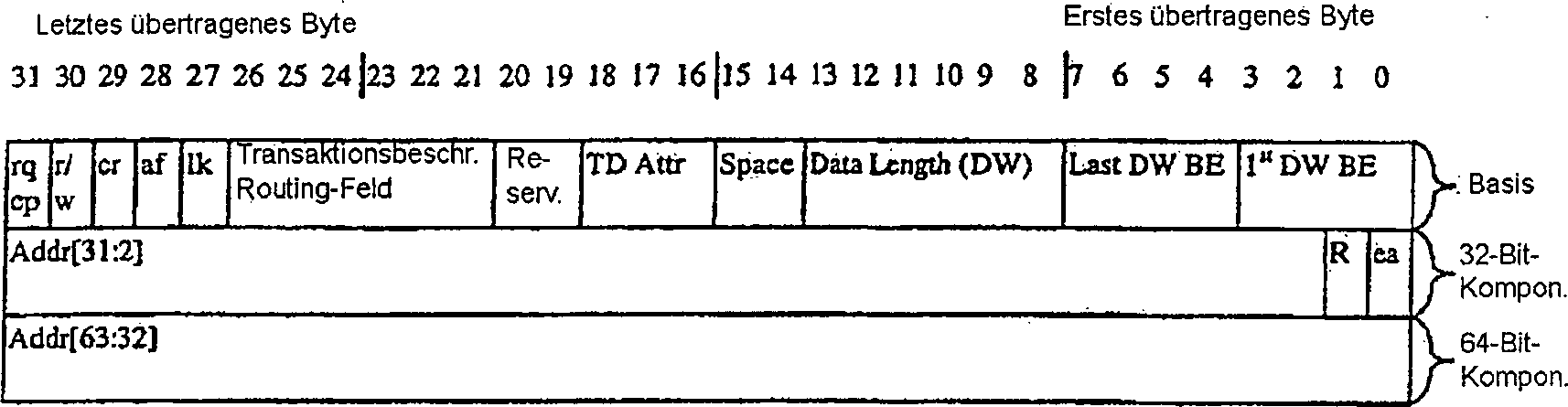
Das Paket-Header-Format für Anforderungspakete gemäß einem Ausführungsbeispiel ist in den Tabellen 5 und 6 dargestellt. In den Beispielen aus den Tabellen 5 und 6 entspricht der Basis-Header einem Doppelwort, wobei ein zusätzliches Doppelwort für die 32-Bit-Adressierung benötigt wird, und wobei zwei zusätzliche Doppelwörter für den 64-Bit- Adressierungsmodus benötigt werden. Die Felder der Header gemäß den Darstellungen in den Tabelle 5 und 6 werden anschließend an die Tabellen beschrieben.The Package header format for Request packages according to a embodiment is shown in Tables 5 and 6. In the examples of the Tables 5 and 6 correspond to the basic header of a double word, where an additional Double word for the 32-bit addressing needed is, and where two additional double words for the 64-bit addressing mode needed become. The fields of the headers according to the representations in the Tables 5 and 6 subsequently become to the tables.
In
alternativen Ausführungsbeispielen
des Hub-Link können
die Felder in dem Header des Anforderungspakets variieren, ohne
dabei vom Umfang der vorliegenden Erfindung abzuweichen. Zum Beispiel
kann der Header zusätzliche
Felder, weniger Felder oder andere Felder an Stelle der nachstehend
dargestellten Felder aufweisen. Ferner kann die Codierung der Felder
ebenfalls variieren, ohne dabei vom Umfang der vorliegenden Erfindung
abzuweichen. Tabelle
5: Anforderungspaket-Header-Format für 32-Bit-Adressierung 
Vollzugspaketeimplementation packages
Das Header-Format für ein Vollzugspaket gemäß einem Ausführungsbeispiel ist nachstehend in Tabelle 7 dargestellt. In einem Ausführungsbeispiel handelt es sich bei dem Header um ein Doppelwort. Die Felder der Header gemäß der Darstellung in Tabelle 8 werden im Anschluss an die Tabelle beschrieben.The Header format for a completion package according to a embodiment is shown in Table 7 below. In one embodiment is the header a double word. The fields of Header as shown in Table 8 are described following the table.
In
alternativen Ausführungsbeispielen
des Hub-Link können
die in dem Header für
ein Vollzugspaket enthaltenen Felder jedoch variieren, ohne dabei
vom Umfang der vorliegenden Erfindung abzuweichen. Zum Beispiel
kann der Header zusätzliche
Felder, weniger Felder oder andere Felder an Stelle der beschriebenen und
nachstehend dargestellten Felder aufweisen. Ferner kann die Codierung
der Felder ebenfalls variieren, ohne dabei vom Umfang der Erfindung
abzuweichen. 
In einem Ausführungsbeispiel des Hub-Link können Ausführungen bzw. Vollzüge für Speicherleseoperationen weniger als die vollständige angeforderte Datenmenge bereitstellen, solange die vollständige Anforderung letztlich ausgeführt wird. In ähnlicher Weise können Vollzüge für Speicherschreiboperationen anzeigen, dass weniger als die ganze Anforderung ausgeführt worden ist. Dies kann vorgenommen werden, um eine bestimmte Hub-Link-Schnittstellenlatenzanforderung für eine bestimmte Plattform zu erfüllen.In an embodiment of the hub link versions or executions for memory read operations less than the full one to provide the requested amount of data as long as the complete request ultimately executed becomes. In similar Way you can full trains for memory write operations Show that less than the whole request has been executed is. This can be done to a specific hub link interface latency request for one to fulfill certain platform.
Für eine Anforderung, welche einen Vollzug erfordert, verwaltet der Initiator in einem Ausführungsbeispiel darüber hinaus Informationen über die Anforderung, die in einem Puffer des einleitenden Hub-Agenten gespeichert werden können. Zum Beispiel können diese Informationen den Transaktionsdeskriptor, die Größe des Pakets, den Sperrstatus, Routing-Informationen, etc. aufweisen. Beim Empfang des Vollzugs bzw. der Vollzüge passt der Initiator ferner den Vollzug bzw. die Vollzüge an die entsprechende Anforderung an. Für den Fall mehrerer Vollzüge akkumuliert der Initiator einen Zählwert der für die ursprüngliche Anforderung ausgeführten Daten, bis die ursprüngliche Anforderung vollständig ausgeführt ist.For a request, which requires a completion, the initiator manages in one embodiment about that In addition, information about the request stored in a buffer of the initiating hub agent can be. For example, you can this information the transaction descriptor, the size of the package, lock status, routing information, etc. have. On receipt of the execution or the execution suits the initiator further the execution or the execution of the corresponding request at. For the case of several executions the initiator accumulates a count of that for the original request executed Data until the original one Requirement completely accomplished is.
Schnittstellen-Arbitrierung und PaketbegrenzungInterface Arbitration and package limitation
Wenn in einem Ausführungsbeispiel der Hub-Schnittstelle sich die Schnittstelle im Ruhezustand befindet, so gilt die Geltendmachung bzw. Aktivierung von einem mit der Schnittstelle verbundenen Hub-Agenten als ein Arbitrierungsereignis. Der erste Agent, der eine Anforderung stellt, gewinnt die Herrschaft über die Schnittstelle. Wenn der Agent die Herrschaft gleichzeitig zu dem Zustand anfordert, wenn der Hub-Link sich im Ruhezustand befindet, so ist der zuletzt behandelte Hub-Agent erfolgreich. In einem Ausführungsbeispiel verfolgen alle Hub-Agenten den zuletzt behandelten Status bzw. Zustand (z.B. über eine Statusflagge eines internen Registers). In einem alternativen Ausführungsbeispiel können alternative Arbitrierungsroutinen gemäß dem Umfang der vorliegenden Erfindung verwendet werden.If in one embodiment the hub interface, the interface is in hibernation, so the assertion or activation of one with the interface applies connected hub agents as an arbitration event. The first Agent making a request gains control of the interface. If the agent requests control of the state at the same time if the hub link is in hibernation, it is the last one handled Hub Agent successfully. In one embodiment, everyone is following Hub agents the most recently handled status (e.g., via a Status flag of an internal register). In an alternative embodiment can alternative arbitration routines according to the scope of the present invention Invention can be used.
Nachdem ein Hub-Agent die Herrschaft über die Schnittstelle errungen hat, beherrscht er die Schnittstelle, bis die Transaktion ausgeführt ist oder bis eine zugewiesene zeitliche Bandbreite abgelaufen ist. In einem Ausführungsbeispiel ist zum Beispiel in jedem Hub-Agenten ein Zeitscheibenzähler bereitgestellt, um die Bandbreitenzuordnung zu steuern bzw. zu regeln und um die Dauer der Herrschaft über eine Schnittstelle für einen Agenten zu begrenzen. Die einem Hub-Agenten zugeordnete Zeit (d.h. der Zeitscheibenwert) kann für die Hub-Link-Agenten, die mit der gleichen Schnittstelle verbunden sind, unterschiedlich oder gleich sein. Der Zeitscheibenzähler startet mit dem Erlangen der Herrschaft über die Schnittstelle und zählt Hub-Link-Basistaktperioden.After a hub agent gains control of the interface, it controls the interface until the transaction completes or until an allocated timeout expires. For example, in one embodiment, a time slot counter is provided in each hub agent to control bandwidth allocation and to limit the duration of control over an interface for an agent. The time allocated to a hub agent (ie, the time slot value) may be different or the same for the hub-link agents connected to the same interface. Of the Time slice counter starts gaining control of the interface and counts stroke-link base clock periods.
In einem Ausführungsbeispiel ist jeder Hub-Agent dafür zuständig, seine eigene Zeitscheibenzuordnung zu verwalten. In einem Ausführungsbeispiel kann diesbezüglich ein Zeitscheibenwert über ein Hub-Link-Befehlsregister für jede Schnittstelle in jedem Hub-Agenten programmiert werden.In an embodiment is every hub agent for it responsible, to manage its own time slice assignment. In one embodiment can in this regard a time slice value over a hub link command register for every interface in every hub agent be programmed.
Die
Abbildung aus
In
einem Ausführungsbeispiel
ist eine Verzögerung
um zwei Takte gegeben, bevor die übermittelten Daten (d.h. Daten
von dem Agenten A) in dem Empfänger
(d.h. Agent B) zur Verfügung
stehen, beginnend mit der Taktflanke 3. Das erste Paket besteht
aus zwei Doppelwörtern
Flusssteuerungflow control
In einem Ausführungsbeispiel können Pakete durch einen empfangenden Agenten wiederholt oder getrennt werden aufgrund des Fehlens von Anforderungswarteschlangenplatz, Datenpufferplatz sowie aus anderen Gründen. In einem Ausführungsbeispiel wird die Flusssteuerung unter Verwendung eines Signals STOP erreicht.In an embodiment can Packets repeated or disconnected by a receiving agent are due to the lack of request queue space, Data buffer space and for other reasons. In one embodiment the flow control is achieved using a STOP signal.
Die
Abbildung aus
Nach
einer Verzögerung
um zwei Takte stehen die von dem Agenten A übermittelten Daten in dem Empfänger an
dem Agenten B zur Verfügung,
beginnend von der Taktflanke 3. In einem Ausführungsbeispiel besteht nach
dem Empfang der von dem Agenten A übermittelten Daten die erste
Möglichkeit
für den
Agenten B, die Flusssteuerung einzuleiten, indem das Signal STOP
geltend gemacht wird, wie dies in der Abbildung aus
Wenn ferner die Herrschaft über das PD-Signal ferner von einem Hub-Agenten zu einem anderen Agenten wechselt, wird auch die Herrschaft über das Signal STOP nach einer vorbestimmten Anzahl von Takten ausgetauscht. In einem Ausführungsbeispiel wird das Signal STOP ferner bei den Basistakten abgetastet, was der letztendlichen Übertragung einer Paketbreite entspricht. Zum Beispiel in einem 4x Modus (unter Verwendung eines PD-Signals mit einer Breite von acht Bit) wird das Signal STOP bei jedem Basistakt abgetastet. In Bezug auf einen 1x Modus wird das Signal STOP jedoch bei jedem vierten Takt abgetastet (wobei der Anfang einer Transaktion als ein Referenzpunkt verwendet wird).If furthermore the rule over the PD signal also from a hub agent to another agent changes, also the rule over the signal STOP after one exchanged predetermined number of clocks. In one embodiment the signal STOP is further sampled at the base clocks, which the final transmission corresponds to a package width. For example in a 4x mode (under Using a PD signal with a width of eight bits) the signal STOP is sampled at each base clock. In terms of one 1x mode, however, the STOP signal is sampled every fourth clock (where the beginning of a transaction uses as a reference point becomes).
Nach
dem Empfang eines Signals STOP, bestimmt der Hub-Agent, der das
Signal STOP empfängt, ob
er das Senden weiterer Pakete wiederholen soll. Die Abbildung aus
In
dem Schritt
Wenn
der Empfänger
des Signals STOP bestimmt, dass der Agent, der das Signal STOP gesendet hat,
nicht die Herrschaft bzw. Kontrolle über die Schnittstelle anfordert,
so kann in dem Schritt
Wenn
die Zeitscheibe für
den aktuellen Eigentümer
bzw. Herrscher über
die Schnittstelle abgelaufen ist, gibt der aktuelle Eigentümer in dem
Schritt
Wenn
der aktuelle Eigentümer
ei Paket mit einem anderen Attribut aufweist, kann der aktuelle
Eigentümer
in dem Schritt
PHYSIKALISCHE SCHNITTSTELLEPHYSICAL INTERFACE
In einem Ausführungsbeispiel implementiert die Hub-Link-Schnittstelle eine physikalische Schnittstelle, die mit einer Grundfrequenz von 66 MHz oder 100 MHz arbeitet. Andere Frequenzen können ebenfalls verwendet werden. Darüber hinaus verwendet die physikalische Schnittstelle in einem Ausführungsbeispiel eine quellensynchrone (SS) Datenübertragungstechnik, die Vierfachtaktung aufweisen kann, um Daten mit dem vierfachen Takt des Basis-Hub-Link-Takts zu übertragen. In einem Ausführungsbeispiel mit einer 8-Bit-Datenschnittstelle (z.B. PD), die mit einer Basisfrequenz von 66 MHz oder 100 MHz arbeitet, kann somit entsprechend eine Bandbreite von 266 Megabyte pro Sekunde (MB/Sek.) oder 400 MB/Sek. erreicht werden.In an embodiment implements the hub-link interface a physical interface, which works with a base frequency of 66 MHz or 100 MHz. Other Frequencies can also be used. About that In addition, in one embodiment, the physical interface uses a source-synchronous (SS) data transmission technique, The quadruple clocking may have four times data Transmit clock of the base hub link clock. In one embodiment with an 8-bit data interface (e.g., PD) operating at a base frequency of 66 MHz or 100 MHz, can thus provide a bandwidth accordingly 266 megabytes per second (MB / sec) or 400 MB / sec. reached become.
In einem Ausführungsbeispiel unterstützt die Hub-Link-Schnittstelle ferner einen Spannungsbetrieb von 1,8 V und basiert auf einem Signalisierungsverfahren der CMOS-Technik (Komplementär-Metalloxid-Halbleiter). In alternativen Ausführungsbeispielen kann die Schnittstelle aber auch auf alternativen Frequenzen und/oder Datenschnittstellen anderer Größen arbeiten bzw. betrieben werden, so dass unterschiedliche Bandbreiten bereitgestellt und alternative Betriebsspannungen unterstützt werden, auf der Basis einer alternativen Signalverarbeitung, ohne dabei vom Umfang der Erfindung abzuweichen.In an embodiment supports the hub-link interface also has a voltage operation of 1.8 V and is based on a signaling method of the CMOS technique (Complementary Metal Oxide Semiconductor). In alternative embodiments However, the interface may also be on alternative frequencies and / or Data interfaces of other sizes work or operated so that different bandwidths provided and alternative operating voltages are supported, based on a alternative signal processing without departing from the scope of the invention departing.
Externe SignaldefinitionExternal signal definition
Die
Abbildung aus
Darüber hinaus verbindet ein unidirektionales Arbitrierungssignal jeden Agenten mit dem anderen (RQa, RQb), und ein bidirektionales Signal STOP wird von dem empfangenden Agenten eingesetzt, um den Datenfluss zu steuern, wie dies vorstehend im Text beschrieben worden ist. Zu weiteren Schnittstellensignalen zählen Systemrückstellung (Reset), gemeinsamer Takt (HLCLK) und Spannungsreferenzsignale (HLVREF). Ebenfalls enthalten sind ferner Signale für jeden Hub-Agenten (ZCOMP) zur Anpassung dessen Treiberausgangsimpedanz an den entsprechenden Wert, um Fertigungs- und Temperaturschwankungen zu kompensieren.Furthermore A unidirectional arbitration signal connects each agent with the other (RQa, RQb), and a bidirectional STOP signal is used by the receiving agent to control the data flow to control, as described above in the text. Other interface signals include system reset (Reset), common clock (HLCLK) and voltage reference signals (HLVREF). Also Also included are signals for each Hub Agent (ZCOMP) to adjust its driver output impedance to the appropriate value, to manufacturing and temperature fluctuations to compensate.
Die
physikalischen Signale, die in der Schnittstelle aus
- 1ASTS = Aktiv erhaltener Dreizustand
- 2SS = Quellensynchrones Modussignal
- 3CC = Gemeinamer Taktmodussignal
- 4In einem Ausführungsbeispiel handelt es sich bei Reset um ein systemweites Signal; es ist eine Ausgabe einer Komponente des Systems und eine Eingabe in die andere(n) Komponente(n). Ferner ist Reset asynchron in Bezug auf HLCLK.
- 1 ASTS = active tri-state
- 2 SS = source synchronous mode signal
- 3 CC = common clock mode signal
- 4 In one embodiment, Reset is a system wide signal; it is an output of one component of the system and an input to the other component (s). Furthermore, Reset is asynchronous with respect to HLCLK.
Betrieb im Übertragungsmodus gemeinsamer TaktOperation in transmission mode common tact
In einem Ausführungsbeispiel werden zahlreiche der über die Hub-Link-Schnittstelle übertragenen Signale gemäß einem gemeinsamen Taktmodus übertragen. Im Besonderen steht die Taktung der Signale, die über den gemeinsamen Taktmodus übertragen werden, im Verhältnis zu einem einzelnen Takt (z.B. dem Hub Link-Takt). In alternativen Ausführungsbeispielen können die Signale mit einem Systemtakt gekoppelt werden, der außerhalb der Hub-Link-Agenten liegt. Ferner können mehr als ein Hub-Link-Segment vorhanden sein, wobei in diesem Fall unterschiedliche Basistakte für die verschiedenen Segmente eingesetzt werden können. Zum Beispiel kann eine Komponente sowohl eine 66 MHz Basis-Hub-Link-Schnittstelle als auch eine 100 MHz Basis-Hub-Link-Schnittstelle implementieren.In an embodiment many will be over transmit the hub-link interface Signals according to a transmitted common clock mode. In particular, the timing of the signals passing through the transmitted common clock mode be, in proportion to a single clock (e.g., the hub link clock). In alternative embodiments can the signals are coupled to a system clock that is outside the hub link agent is located. Furthermore, more than one hub link segment can be used be present, in which case different base clocks for the different segments can be used. For example, a Component both a 66 MHz base hub link interface as well implement a 100 MHz base hub link interface.
Betrieb im quellensynchronen ÜbertragungsmodusOperation in source synchronous transmission mode
In einem Ausführungsbeispiel werden die Pakete/Daten unter Verwendung eines quellensynchronen Taktmodus übermittelt, der eine Technik zur Multiplikation der Datenübertragungsrate bereitstellt. In einem Ausführungsbeispiel unter Verwendung eines 4x quellensynchronen Taktmodus mit einem 8-Bit-Datensignalpfad, erfordert die Übermittlung eines Doppelwortes (d.h. vier Byte) nur einen Hub-Link-Taktzyklus (HLCK). Alternativ würde die Übermittlung eines Doppelwortes unter Verwendung eines 1X quellensynchronen Taktmodus auf einem 8-Bit-Datensignalpfad einen vollständigen Hub-Link-Taktzyklus für die vollständige Ausführung erfordern.In an embodiment the packets / data are transmitted using a source-synchronous clock mode, which provides a technique for multiplying the data transmission rate. In one embodiment using a 4x source synchronous clock mode with one 8-bit data signal path, requires the transmission of a double word (i.e., four bytes) only one Hub Link Clock Cycle (HLCK). alternative would the transmission a double word using a 1X source synchronous clock mode on an 8-bit data signal path a full hub-link clock cycle for the full Require execution.
Im Besonderen werden in einem Ausführungsbeispiel der quellensynchronen Übermittlung Strobes (z.B. PSTRBN/PSTRBP) mit einer Datenübermittlung gemäß einem vorbestimmten Taktverhältnis zwischen den Strobes und den Daten gesendet. Die Strobes werden danach von dem empfangenden Hub-Agenten zur Verriegelung der Daten in dem empfangenden Hub-Agenten verwendet.in the Particulars are in one embodiment the source synchronous transmission Strobes (e.g., PSTRBN / PSTRBP) with data transmission in accordance with a predetermined duty cycle sent between the strobes and the data. The strobes will be then from the receiving hub agent to lock the data in the receiving hub agent used.
Im
Besonderen werden in einem Ausführungsbeispiel
die Flanken der Strobes PSTRBP/S'PSTRBN von
dem empfangenden Hub-Agenten eingesetzt, um die Gegenwart und Taktung
der über
die Datensignalpfade übertragenen
Daten zu identifizieren. Wie dies zum Beispiel in dem Taktdiagramm
aus
In
einem weiteren Ausführungsbeispiel,
das in der Abbildung aus
In
der vorstehenden Patentschrift wurde die vorliegende Erfindung in
Bezug auf bestimmte exemplarische Ausführungsbeispiele der Erfindung
beschrieben. Es ist jedoch ersichtlich, dass verschiedene Modifikationen
und Änderungen
diesbezüglich
vorgenommen werden können,
ohne dabei vom Umfang der Erfindung abzuweichen. Zum Beispiel kann
die Hub-Link-Schnittstelle
gemäß einem
Ausführungsbeispiel
in einem Computersystem mit mehreren Prozessoren implementiert werden,
wie dies in der Abbildung aus
Claims (21)
Applications Claiming Priority (3)
| Application Number | Priority Date | Filing Date | Title |
|---|---|---|---|
| US09/186,219 US6145039A (en) | 1998-11-03 | 1998-11-03 | Method and apparatus for an improved interface between computer components |
| US186219 | 1998-11-03 | ||
| PCT/US1999/025630 WO2000026798A1 (en) | 1998-11-03 | 1999-11-01 | Method and apparatus for an improved interface between computer components |
Publications (2)
| Publication Number | Publication Date |
|---|---|
| DE69936060D1 DE69936060D1 (en) | 2007-06-21 |
| DE69936060T2 true DE69936060T2 (en) | 2008-01-10 |
Family
ID=22684111
Family Applications (1)
| Application Number | Title | Priority Date | Filing Date |
|---|---|---|---|
| DE69936060T Expired - Lifetime DE69936060T2 (en) | 1998-11-03 | 1999-11-01 | Method and apparatus for an improved interface between computer components |
Country Status (9)
| Country | Link |
|---|---|
| US (1) | US6145039A (en) |
| EP (1) | EP1127318B1 (en) |
| KR (1) | KR100417839B1 (en) |
| CN (1) | CN1253802C (en) |
| AU (1) | AU1461000A (en) |
| DE (1) | DE69936060T2 (en) |
| HK (1) | HK1036853A1 (en) |
| TW (1) | TW476885B (en) |
| WO (1) | WO2000026798A1 (en) |
Families Citing this family (48)
| Publication number | Priority date | Publication date | Assignee | Title |
|---|---|---|---|---|
| US6665807B1 (en) | 1998-09-04 | 2003-12-16 | Hitachi, Ltd. | Information processing apparatus |
| JP3592547B2 (en) * | 1998-09-04 | 2004-11-24 | 株式会社ルネサステクノロジ | Information processing apparatus and signal transfer method |
| US20030110317A1 (en) * | 1998-11-03 | 2003-06-12 | Jasmin Ajanovic | Method and apparatus for an improved interface between a memory control hub and an input/output control hub |
| US6362826B1 (en) * | 1999-01-15 | 2002-03-26 | Intel Corporation | Method and apparatus for implementing dynamic display memory |
| US6345072B1 (en) | 1999-02-22 | 2002-02-05 | Integrated Telecom Express, Inc. | Universal DSL link interface between a DSL digital controller and a DSL codec |
| US6311285B1 (en) * | 1999-04-27 | 2001-10-30 | Intel Corporation | Method and apparatus for source synchronous transfers at frequencies including an odd fraction of a core frequency |
| US6813251B1 (en) * | 1999-07-27 | 2004-11-02 | Intel Corporation | Split Transaction protocol for a bus system |
| US6792495B1 (en) * | 1999-07-27 | 2004-09-14 | Intel Corporation | Transaction scheduling for a bus system |
| US6687240B1 (en) * | 1999-08-19 | 2004-02-03 | International Business Machines Corporation | Transaction routing system |
| US6636912B2 (en) * | 1999-10-07 | 2003-10-21 | Intel Corporation | Method and apparatus for mode selection in a computer system |
| US6721859B1 (en) * | 1999-10-21 | 2004-04-13 | Sony Corporation | Multi-protocol media storage device implementing protocols optimized for storing and retrieving both asynchronous and isochronous data |
| US6496895B1 (en) * | 1999-11-01 | 2002-12-17 | Intel Corporation | Method and apparatus for intializing a hub interface |
| US6615306B1 (en) * | 1999-11-03 | 2003-09-02 | Intel Corporation | Method and apparatus for reducing flow control and minimizing interface acquisition latency in a hub interface |
| US7039047B1 (en) | 1999-11-03 | 2006-05-02 | Intel Corporation | Virtual wire signaling |
| US6347351B1 (en) * | 1999-11-03 | 2002-02-12 | Intel Corporation | Method and apparatus for supporting multi-clock propagation in a computer system having a point to point half duplex interconnect |
| US6516375B1 (en) | 1999-11-03 | 2003-02-04 | Intel Corporation | Peripheral component interconnect (PCI) configuration emulation for hub interface |
| US6560666B1 (en) * | 1999-11-23 | 2003-05-06 | Intel Corporation | Hub link mechanism for impedance compensation update |
| US7512082B1 (en) * | 1999-12-14 | 2009-03-31 | Intel Corporation | Tracking transaction status for a bus system providing legacy bus compatibility |
| US6542946B1 (en) * | 2000-01-28 | 2003-04-01 | Compaq Information Technologies Group, L.P. | Dual mode differential transceiver for a universal serial bus |
| US6842813B1 (en) * | 2000-06-12 | 2005-01-11 | Intel Corporation | Method and apparatus for single wire signaling of request types in a computer system having a point to point half duplex interconnect |
| US7720821B1 (en) | 2000-06-30 | 2010-05-18 | Sony Corporation | Method of and apparatus for writing and reading time sensitive data within a storage device |
| EP1179785A1 (en) * | 2000-08-07 | 2002-02-13 | STMicroelectronics S.r.l. | Bus interconnect system |
| US6877052B1 (en) | 2000-09-29 | 2005-04-05 | Intel Corporation | System and method for improved half-duplex bus performance |
| US6910093B2 (en) * | 2000-12-07 | 2005-06-21 | Micron Technology, Inc. | Method of pacing and disconnecting transfers on a source strobed bus |
| US7058823B2 (en) * | 2001-02-28 | 2006-06-06 | Advanced Micro Devices, Inc. | Integrated circuit having programmable voltage level line drivers and method of operation |
| US6813673B2 (en) * | 2001-04-30 | 2004-11-02 | Advanced Micro Devices, Inc. | Bus arbitrator supporting multiple isochronous streams in a split transactional unidirectional bus architecture and method of operation |
| US6912611B2 (en) * | 2001-04-30 | 2005-06-28 | Advanced Micro Devices, Inc. | Split transactional unidirectional bus architecture and method of operation |
| US6785758B1 (en) | 2001-06-01 | 2004-08-31 | Advanced Micro Devices, Inc. | System and method for machine specific register addressing in a split transactional unidirectional bus architecture |
| US6763415B1 (en) | 2001-06-08 | 2004-07-13 | Advanced Micro Devices, Inc. | Speculative bus arbitrator and method of operation |
| US7028124B2 (en) * | 2001-09-26 | 2006-04-11 | Intel Corporation | Method and apparatus for dual queue head processing of interrupt endpoints |
| US6889265B2 (en) | 2001-11-05 | 2005-05-03 | Intel Corporation | Apparatus and method to allow and synchronize schedule changes in a USB enhanced host controller |
| US7006533B2 (en) * | 2002-02-19 | 2006-02-28 | Intel Corporation | Method and apparatus for hublink read return streaming |
| US7043667B2 (en) * | 2002-05-14 | 2006-05-09 | Intel Corporation | Debug information provided through tag space |
| US7120722B2 (en) * | 2002-05-14 | 2006-10-10 | Intel Corporation | Using information provided through tag space |
| US20030217301A1 (en) * | 2002-05-16 | 2003-11-20 | Levy Paul S. | Method and apparatus for transmitting side-band data within a source synchronous clock signal |
| US7133972B2 (en) | 2002-06-07 | 2006-11-07 | Micron Technology, Inc. | Memory hub with internal cache and/or memory access prediction |
| US7117316B2 (en) * | 2002-08-05 | 2006-10-03 | Micron Technology, Inc. | Memory hub and access method having internal row caching |
| US6820181B2 (en) | 2002-08-29 | 2004-11-16 | Micron Technology, Inc. | Method and system for controlling memory accesses to memory modules having a memory hub architecture |
| US7120743B2 (en) | 2003-10-20 | 2006-10-10 | Micron Technology, Inc. | Arbitration system and method for memory responses in a hub-based memory system |
| US7330992B2 (en) | 2003-12-29 | 2008-02-12 | Micron Technology, Inc. | System and method for read synchronization of memory modules |
| US7210000B2 (en) * | 2004-04-27 | 2007-04-24 | Intel Corporation | Transmitting peer-to-peer transactions through a coherent interface |
| US20080005378A1 (en) * | 2006-05-19 | 2008-01-03 | Intel Corporation | Chipset determinism for improved validation |
| US7702832B2 (en) * | 2006-06-07 | 2010-04-20 | Standard Microsystems Corporation | Low power and low pin count bi-directional dual data rate device interconnect interface |
| US8806093B2 (en) * | 2010-04-01 | 2014-08-12 | Intel Corporation | Method, apparatus, and system for enabling a deterministic interface |
| CN102133308A (en) * | 2011-03-04 | 2011-07-27 | 邹天琼 | Capsule for removing toxin and eliminating fat |
| TWI506443B (en) * | 2012-12-27 | 2015-11-01 | Mediatek Inc | Media peripheral interface and communication method between processor and peripheral device |
| US9946683B2 (en) | 2014-12-24 | 2018-04-17 | Intel Corporation | Reducing precision timing measurement uncertainty |
| CN117290278A (en) * | 2023-10-10 | 2023-12-26 | 合芯科技有限公司 | Chip hardware interconnection structure, chip, server and method |
Family Cites Families (25)
| Publication number | Priority date | Publication date | Assignee | Title |
|---|---|---|---|---|
| DE4033417A1 (en) * | 1990-10-20 | 1992-04-23 | Basf Ag | METHOD FOR THE PRODUCTION OF ZINCOXIDE PIGMENTS DOPED WITH METAL OXIDS |
| US5191649A (en) * | 1990-12-21 | 1993-03-02 | Intel Corporation | Multiprocessor computer system with data bus and ordered and out-of-order split data transactions |
| JP3411300B2 (en) * | 1992-02-18 | 2003-05-26 | 株式会社日立製作所 | Information processing device |
| US5553310A (en) * | 1992-10-02 | 1996-09-03 | Compaq Computer Corporation | Split transactions and pipelined arbitration of microprocessors in multiprocessing computer systems |
| US5590292A (en) * | 1992-12-08 | 1996-12-31 | Compaq Computer Corporation | Scalable tree structured high speed input/output subsystem architecture |
| US5687388A (en) * | 1992-12-08 | 1997-11-11 | Compaq Computer Corporation | Scalable tree structured high speed input/output subsystem architecture |
| US5469435A (en) * | 1994-01-25 | 1995-11-21 | Apple Computer, Inc. | Bus deadlock avoidance during master split-transactions |
| US5533204A (en) * | 1994-04-18 | 1996-07-02 | Compaq Computer Corporation | Split transaction protocol for the peripheral component interconnect bus |
| US5546546A (en) * | 1994-05-20 | 1996-08-13 | Intel Corporation | Method and apparatus for maintaining transaction ordering and arbitrating in a bus bridge |
| US5621897A (en) * | 1995-04-13 | 1997-04-15 | International Business Machines Corporation | Method and apparatus for arbitrating for a bus to enable split transaction bus protocols |
| US5996036A (en) * | 1997-01-07 | 1999-11-30 | Apple Computers, Inc. | Bus transaction reordering in a computer system having unordered slaves |
| US5933612A (en) * | 1995-05-02 | 1999-08-03 | Apple Computer, Inc. | Deadlock avoidance in a split-bus computer system |
| US5761444A (en) * | 1995-09-05 | 1998-06-02 | Intel Corporation | Method and apparatus for dynamically deferring transactions |
| US5978874A (en) * | 1996-07-01 | 1999-11-02 | Sun Microsystems, Inc. | Implementing snooping on a split-transaction computer system bus |
| US5911052A (en) * | 1996-07-01 | 1999-06-08 | Sun Microsystems, Inc. | Split transaction snooping bus protocol |
| US5802055A (en) * | 1996-04-22 | 1998-09-01 | Apple Computer, Inc. | Method and apparatus for dynamic buffer allocation in a bus bridge for pipelined reads |
| US6021456A (en) * | 1996-11-12 | 2000-02-01 | Herdeg; Glenn Arthur | Method for communicating interrupt data structure in a multi-processor computer system |
| US6012118A (en) * | 1996-12-30 | 2000-01-04 | Intel Corporation | Method and apparatus for performing bus operations in a computer system using deferred replies returned without using the address bus |
| US5832243A (en) * | 1996-12-31 | 1998-11-03 | Compaq Computer Corporation | Computer system implementing a stop clock acknowledge special cycle |
| US5870567A (en) * | 1996-12-31 | 1999-02-09 | Compaq Computer Corporation | Delayed transaction protocol for computer system bus |
| US5918025A (en) * | 1996-12-31 | 1999-06-29 | Intel Corporation | Method and apparatus for converting a five wire arbitration/buffer management protocol into a two wire protocol |
| US5930485A (en) * | 1997-01-07 | 1999-07-27 | Apple Computer, Inc. | Deadlock avoidance in a computer system having unordered slaves |
| US5991824A (en) * | 1997-02-06 | 1999-11-23 | Silicon Graphics, Inc. | Method and system for simultaneous high bandwidth input output |
| US5909594A (en) * | 1997-02-24 | 1999-06-01 | Silicon Graphics, Inc. | System for communications where first priority data transfer is not disturbed by second priority data transfer and where allocated bandwidth is removed when process terminates abnormally |
| US5944805A (en) * | 1997-08-21 | 1999-08-31 | Advanced Micro Devices, Inc. | System and method for transmitting data upon an address portion of a computer system bus during periods of maximum utilization of a data portion of the bus |
-
1998
- 1998-11-03 US US09/186,219 patent/US6145039A/en not_active Expired - Lifetime
-
1999
- 1999-10-20 TW TW088118121A patent/TW476885B/en not_active IP Right Cessation
- 1999-11-01 DE DE69936060T patent/DE69936060T2/en not_active Expired - Lifetime
- 1999-11-01 EP EP99971542A patent/EP1127318B1/en not_active Expired - Lifetime
- 1999-11-01 AU AU14610/00A patent/AU1461000A/en not_active Abandoned
- 1999-11-01 WO PCT/US1999/025630 patent/WO2000026798A1/en active IP Right Grant
- 1999-11-01 CN CNB998153990A patent/CN1253802C/en not_active Expired - Fee Related
- 1999-11-01 KR KR10-2001-7005542A patent/KR100417839B1/en not_active IP Right Cessation
-
2001
- 2001-09-29 HK HK01106917A patent/HK1036853A1/en not_active IP Right Cessation
Also Published As
| Publication number | Publication date |
|---|---|
| CN1348565A (en) | 2002-05-08 |
| CN1253802C (en) | 2006-04-26 |
| TW476885B (en) | 2002-02-21 |
| EP1127318B1 (en) | 2007-05-09 |
| HK1036853A1 (en) | 2002-01-18 |
| KR100417839B1 (en) | 2004-02-11 |
| EP1127318A1 (en) | 2001-08-29 |
| DE69936060D1 (en) | 2007-06-21 |
| US6145039A (en) | 2000-11-07 |
| AU1461000A (en) | 2000-05-22 |
| WO2000026798A1 (en) | 2000-05-11 |
| EP1127318A4 (en) | 2004-04-14 |
| KR20010092432A (en) | 2001-10-24 |
Similar Documents
| Publication | Publication Date | Title |
|---|---|---|
| DE69936060T2 (en) | Method and apparatus for an improved interface between computer components | |
| DE60013470T2 (en) | DEVICE FOR INITIALIZING A COMPUTER INTERFACE | |
| DE69932400T2 (en) | Control device for a port manager for the connection of different functional modules | |
| DE69836426T2 (en) | Control unit for a universal serial bus | |
| DE3909948C2 (en) | ||
| DE60037036T2 (en) | FOUR-PUMPED BUS ARCHITECTURE / LOG | |
| DE69834519T2 (en) | Bus control system and method | |
| EP0929041B1 (en) | Method and arrangement for operating a bus system | |
| DE69531933T2 (en) | BUS ARCHITECTURE IN HIGH GRADE PIPELINE VERSION | |
| DE19900369A9 (en) | Execution of control transmission on universal serial bus communication system | |
| DE19982854B4 (en) | Method and apparatus for minimizing idle conditions of an asynchronous transmit fax and overflow conditions of a receive FIFO | |
| DE60125112T2 (en) | PCI arbiter with voltage controllable control support | |
| DE69736872T2 (en) | Data processing system | |
| DE60017774T2 (en) | METHOD AND DEVICE FOR SUPPORTING MULTIPACTIVE TRANSMISSION IN A COMPUTER SYSTEM WITH A POINT-TO-POINT HALF-DUPLEX CONNECTION | |
| DE4142756A1 (en) | DATA WAY SETUP FOR COUPLING TWO BUSES | |
| DE4018481C2 (en) | ||
| DE10296959T5 (en) | System and method for controlling bus allocation during cache burst cycles | |
| DE19983506B3 (en) | A method of operating a time-multiplexed address and data bus in a computer system and bus interface therefor | |
| DE69724884T2 (en) | Device and method for positive and subtractive address decoding on a bus | |
| DE4035837A1 (en) | MAIN BUS INTERFACE CIRCUIT WITH TRANSPARENT INTERRUPTION OF A DATA TRANSFER OPERATION | |
| DE69726302T2 (en) | BUSSCHNITTSTELLENSTEUERUNGSSCHALTUNG | |
| DE602004012310T2 (en) | MEMORY INTERFACE FOR SYSTEMS WITH MULTIPLE PROCESSORS AND A STORAGE SYSTEM | |
| DE10234992A1 (en) | Retry mechanism for blocking interfaces | |
| DE60029118T2 (en) | ASYNCHRONOUS CENTRALIZED MULTICANAL DMA CONTROL | |
| DE19882975B4 (en) | Access a message exchange unit from a secondary bus |
Legal Events
| Date | Code | Title | Description |
|---|---|---|---|
| 8364 | No opposition during term of opposition | ||
| 8328 | Change in the person/name/address of the agent |
Representative=s name: HEYER, V., DIPL.-PHYS. DR.RER.NAT., PAT.-ANW., 806 |