DE69923947T2 - Steel cable for reinforcing rubber and pneumatic tires - Google Patents
Steel cable for reinforcing rubber and pneumatic tires Download PDFInfo
- Publication number
- DE69923947T2 DE69923947T2 DE69923947T DE69923947T DE69923947T2 DE 69923947 T2 DE69923947 T2 DE 69923947T2 DE 69923947 T DE69923947 T DE 69923947T DE 69923947 T DE69923947 T DE 69923947T DE 69923947 T2 DE69923947 T2 DE 69923947T2
- Authority
- DE
- Germany
- Prior art keywords
- layer
- wires
- intermediate layer
- steel
- steel cable
- Prior art date
- Legal status (The legal status is an assumption and is not a legal conclusion. Google has not performed a legal analysis and makes no representation as to the accuracy of the status listed.)
- Expired - Lifetime
Links
Classifications
-
- B—PERFORMING OPERATIONS; TRANSPORTING
- B29—WORKING OF PLASTICS; WORKING OF SUBSTANCES IN A PLASTIC STATE IN GENERAL
- B29D—PRODUCING PARTICULAR ARTICLES FROM PLASTICS OR FROM SUBSTANCES IN A PLASTIC STATE
- B29D30/00—Producing pneumatic or solid tyres or parts thereof
- B29D30/06—Pneumatic tyres or parts thereof (e.g. produced by casting, moulding, compression moulding, injection moulding, centrifugal casting)
- B29D30/48—Bead-rings or bead-cores; Treatment thereof prior to building the tyre
-
- D—TEXTILES; PAPER
- D07—ROPES; CABLES OTHER THAN ELECTRIC
- D07B—ROPES OR CABLES IN GENERAL
- D07B1/00—Constructional features of ropes or cables
- D07B1/06—Ropes or cables built-up from metal wires, e.g. of section wires around a hemp core
- D07B1/0606—Reinforcing cords for rubber or plastic articles
- D07B1/062—Reinforcing cords for rubber or plastic articles the reinforcing cords being characterised by the strand configuration
- D07B1/0626—Reinforcing cords for rubber or plastic articles the reinforcing cords being characterised by the strand configuration the reinforcing cords consisting of three core wires or filaments and at least one layer of outer wires or filaments, i.e. a 3+N configuration
-
- D—TEXTILES; PAPER
- D07—ROPES; CABLES OTHER THAN ELECTRIC
- D07B—ROPES OR CABLES IN GENERAL
- D07B1/00—Constructional features of ropes or cables
- D07B1/06—Ropes or cables built-up from metal wires, e.g. of section wires around a hemp core
- D07B1/0606—Reinforcing cords for rubber or plastic articles
- D07B1/062—Reinforcing cords for rubber or plastic articles the reinforcing cords being characterised by the strand configuration
- D07B1/0633—Reinforcing cords for rubber or plastic articles the reinforcing cords being characterised by the strand configuration having a multiple-layer configuration
-
- D—TEXTILES; PAPER
- D07—ROPES; CABLES OTHER THAN ELECTRIC
- D07B—ROPES OR CABLES IN GENERAL
- D07B2201/00—Ropes or cables
- D07B2201/10—Rope or cable structures
- D07B2201/104—Rope or cable structures twisted
- D07B2201/1076—Open winding
- D07B2201/108—Cylinder winding, i.e. S/Z or Z/S
-
- D—TEXTILES; PAPER
- D07—ROPES; CABLES OTHER THAN ELECTRIC
- D07B—ROPES OR CABLES IN GENERAL
- D07B2201/00—Ropes or cables
- D07B2201/20—Rope or cable components
- D07B2201/2095—Auxiliary components, e.g. electric conductors or light guides
- D07B2201/2097—Binding wires
-
- D—TEXTILES; PAPER
- D07—ROPES; CABLES OTHER THAN ELECTRIC
- D07B—ROPES OR CABLES IN GENERAL
- D07B2401/00—Aspects related to the problem to be solved or advantage
- D07B2401/20—Aspects related to the problem to be solved or advantage related to ropes or cables
- D07B2401/208—Enabling filler penetration
-
- Y—GENERAL TAGGING OF NEW TECHNOLOGICAL DEVELOPMENTS; GENERAL TAGGING OF CROSS-SECTIONAL TECHNOLOGIES SPANNING OVER SEVERAL SECTIONS OF THE IPC; TECHNICAL SUBJECTS COVERED BY FORMER USPC CROSS-REFERENCE ART COLLECTIONS [XRACs] AND DIGESTS
- Y10—TECHNICAL SUBJECTS COVERED BY FORMER USPC
- Y10S—TECHNICAL SUBJECTS COVERED BY FORMER USPC CROSS-REFERENCE ART COLLECTIONS [XRACs] AND DIGESTS
- Y10S57/00—Textiles: spinning, twisting, and twining
- Y10S57/902—Reinforcing or tire cords
Landscapes
- Engineering & Computer Science (AREA)
- Mechanical Engineering (AREA)
- Ropes Or Cables (AREA)
- Tires In General (AREA)
Description
Die vorliegende Erfindung betrifft ein Gummi und Reifen verstärkendes Stahlseil, das besser von Gummi durchdrungen werden kann, insbesondere ein Stahlseil zur Verstärkung von Reifen und anderen Gummiprodukten, das eine Drillkonstruktion aufweist und eine aus drei Drähten bestehende Innenschicht, eine aus acht Drähten bestehende Zwischenschicht, eine aus dreizehn Drähten bestehende Außenschicht und eine schraubenförmige Umhüllung umfasst, die so ausgebildet sind, dass in das Stahlseil Gummi leicht eindringen kann, wodurch ein besseres Eindringen von Gummi in das Stahlseil erreicht wird.The The present invention relates to a rubber and tire reinforcing Steel rope, which can be better penetrated by rubber, in particular a steel rope for reinforcement of tires and other rubber products that make a drill construction and one out of three wires existing inner layer, an intermediate layer consisting of eight wires, one of thirteen wires existing outer layer and a helical one wrapping includes, which are designed so that in the steel cord rubber easily can penetrate, causing a better penetration of rubber in the Steel rope is reached.
Für Gummi und Reifen verstärkende Stahlseile, die aus mehreren gewundenen Drähten gebildet werden, können verschiedene Konstruktionen verwendet werden. Beispielsweise sind Stahlseile mit dreischichtiger Drillkonstruktion, die drei gewundene Drahtschichten umfasst, bekannt. Solche Stahlseile mit dreischichtiger Drillkonstruktion werden für Lastwagen- und Busreifen verwendet.For rubber and tire reinforcing Steel ropes, which are formed from several winding wires, can be different Constructions are used. For example, steel cables with three-layer drill construction, the three twisted wire layers includes, known. Such steel cables with three-layer drill construction be for Used truck and bus tires.
Einen repräsentativen Standard für ein dreischichtiges Stahlseil stellt eine "1 × 3 + 9 + 15 + U"-Konstruktion dar. Bei einem solchen dreischichtigen Stahlseil mit "1 × 3 + 9 + 15 + U"-Konstruktion umfasst ein eine innere Drahtschicht bildender Kern drei Drähte, die in eine bestimmte Richtung gewunden sind. Eine den Kern umgebende Zwischenschicht umfasst neun gewundene Drähte, die eng am Kern anliegen. Eine die Zwischenschicht umgebende Außenschicht umfasst fünfzehn gewundene Drähte, die eng an der Zwischenschicht anliegen. Eine schraubenförmige Umhüllung, die einen einzigen gewundenen Draht umfasst, umgibt die Außenschicht.a representative Standard for a three-layer steel cable represents a "1 × 3 + 9 + 15 + U "construction. In such a three-layer steel cable with "1 × 3 + 9 + 15 + U "construction a core forming an inner wire layer has three wires; are twisted in a certain direction. A surrounding the core Interlayer includes nine coiled wires that fit tightly against the core. An outer layer surrounding the intermediate layer comprises fifteen convoluted ones wires which lie close to the intermediate layer. A helical cladding that comprising a single twisted wire surrounds the outer layer.
Die drei Drähte der Innenschicht werden zusammen gewunden. Die Zwischenschicht wird gebildet, indem neun Drähte in die gleiche Drillrichtung wie die Innenschicht gewunden werden, aber mit einer anderen Drilllänge als diejenige der Innenschicht. Zur Bildung der Außenschicht werden fünfzehn Drähte, die den gleichen Durchmesser wie diejenigen der Zwischenschicht aufweisen, verdrillt, wobei die Drillrichtung derjenigen der Zwischenschicht entgegengesetzt ist und die Drilllänge sich von derjenigen der Zwischenschicht unterscheidet. Die schraubenförmige Umhüllung wird in eine Richtung gewunden, die derjenigen der Außenschicht entgegengesetzt ist.The three wires the inner layer are wound together. The interlayer becomes formed by nine wires be wound in the same twisting direction as the inner layer, but with a different drill length as that of the inner layer. To form the outer layer be fifteen wires the same diameter as those of the intermediate layer have, twisted, wherein the drilling direction of that of the intermediate layer is opposite and the drill length is different from that of Interlayer differs. The helical cladding becomes unidirectional winding, opposite to that of the outer layer is.
Bei einem solchen Stahlseil ist jedoch wenig oder gar kein Zwischenraum zwischen den Drähten der Außen- und Zwischenschicht. Aus diesem Grund kann kaum Deckgummi in das Stahlseil eindringen, was zu einem schlechten Haftvermögen in Bezug auf Gummi führt. Des Weiteren können aufgrund des unzureichenden Eindringens des Deckgummis in das Stahlseil zwischen den Drähten des Stahlseils Hohlräume vorhanden sein. Solche Hohlräume bilden Kanäle für in das Stahlseil eindringende Flüssigkeiten oder Salze. Wenn dann ein Reifen, für den das Stahlseil verwendet wird, immer wieder durchgebogen wird, kann das Stahlseil schnell korrodieren. Dies führt zu einer geringeren Lebensdauer des Reifens.at However, such a steel cable is little or no gap between the wires the foreign and intermediate layer. For this reason, hardly cover rubber in the Steel rope penetrate, resulting in poor adhesion in terms leads to rubber. Furthermore you can due to insufficient penetration of the cover rubber into the steel cable between the wires of the steel rope cavities to be available. Such cavities form channels for in the steel rope penetrating fluids or salts. If there is a tire for which the steel cable is used is repeatedly bent, the steel cable can corrode quickly. this leads to to a shorter life of the tire.
Darüber hinaus befinden sich die Drähte dieses Stahlseils in Punktberührung oder instabiler Linienberührung miteinander. Aus diesem Grund reiben die Drähte des Stahlseils so aneinander, dass es schnell zu Korrosionsermüdung kommen kann. Diese Korrosionsermüdung wird Reibkorrosion genannt. Diese Reibkorrosion bewirkt eine geringere Lebensdauer des Reifens. Bei der Innen- und Zwischenschicht des Stahlseils befinden sich die Drähte in instabiler Linienberührung miteinander, da diese Schichten zwar die gleiche Drillrichtung aber eine unterschiedliche Drilllänge aufweisen. Im Fall der Außenschicht und der schraubenförmige Umhüllung befinden sich der Draht bzw. die Drähte jeder Schicht aufgrund unterschiedlicher Drillrichtung und Drilllänge dieser Schichten in Punktberührung mit denjenigen der darunter liegenden Schicht.Furthermore are the wires this steel rope in point contact or unstable line contact together. For this reason, the wires of the steel rope rub against each other, that it quickly leads to corrosion fatigue can come. This corrosion fatigue is called fretting corrosion. This fretting corrosion causes a lower Life of the tire. In the inner and intermediate layer of Steel cables are the wires in unstable line contact with each other, since these layers are in the same direction of twisting, though a different drill length exhibit. In the case of the outer layer and the helical sheath are located itself the wire or the wires each layer due to different drill direction and drill length of this Layers in point contact with those of the underlying layer.
Bei der Herstellung eines solchen Stahlseils werden die Innenschicht, die Zwischenschicht, die Außenschicht und die schraubenförmige Umhüllung separat gedrillt. Mit anderen Worten, die Herstellung dieses Stahlseils erfordert gewöhnlich vier Bearbeitungsschritte. Dies führt zu höheren Herstellungskosten.at the production of such a steel cord, the inner layer, the intermediate layer, the outer layer and the helical one wrapping drilled separately. In other words, the production of this steel cable usually requires four processing steps. This leads to higher production costs.
In US-4 158 946 A ist ein Metallseil beschrieben, das alle Merkmale des Oberbegriffs des unabhängigen Anspruchs 1 aufweist. Die Schrift US H 1505 M beschreibt ein Stahlseil, bei dem die Drähte der Zwischenschicht zusammen mit den Drähten der Innenschicht verdrillt werden.In US-A-4 158 946 discloses a metal cord having all the features the generic term of the independent Claim 1 has. The font US H 1505 M describes a steel cable, where the wires the intermediate layer is twisted together with the wires of the inner layer become.
Die vorliegende Erfindung wurde angesichts der oben genannten Probleme gemacht. Daher besteht eine Aufgabe dieser Erfindung darin, ein Stahlseil zur Verstärkung von Reifen und anderen Gummiprodukten zu schaffen, das aus mehreren Schichten gewundener Drähte gebildet ist, zwischen denen sich Hohlräume befinden, die es ermöglichen, dass in das Stahlseil Gummi leicht eindringen kann, wodurch ein besseres Eindringen von Gummi in das Stahlseil sowie eine Verringerung der Reibkorrosion erreicht wird, wobei gleichzeitig die Anzahl der für die Herstellung des Stahlseils erforderlichen Drillsschritte verringert wird und somit die Herstellungskosten gesenkt werden.The present invention has been made in view of the above problems. Therefore, it is an object of this invention to provide a steel cord for reinforcing tires and other rubber products, which is formed of multiple layers of twisted wires between which there are cavities which allow rubber to easily penetrate into the steel cord, thereby creating a better penetration of rubber into the steel cable and a reduction in the fretting corrosion is achieved, at the same time the number of drills required for the production of the steel cord is reduced and thus the production costs are reduced.
Gemäß der vorliegenden Erfindung wird diese Aufgabe durch Schaffung eines Stahlseils nach Anspruch 1 gelöst.According to the present Invention accomplishes this task by providing a steel cord Claim 1 solved.
Weitere Aufgaben und Aspekte dieser Erfindung gehen hervor aus der folgenden Beschreibung von Ausführungen, in der auf die beigefügten Zeichnungen Bezug genommen wird. Es zeigenFurther Objects and aspects of this invention will be apparent from the following Description of designs, in the attached to the Drawings reference is made. Show it
In
Die
Innenschicht
k3
= rechts oder links (vorausgesetzt, k3 ist entgegengesetzt zu k1,
k2 und k4)
wobei d1, d2, d3 und d4 den Drahtdurchmesser der
Innenschicht
k3 = right or left (assuming k3 is opposite to k1, k2 and k4)
where d1, d2, d3 and d4 are the wire diameter of the inner layer
Zur
Bewertung des erfindungsgemäßen Stahlseils,
das die obige Konstruktion aufweist, wurden die physikalischen Eigenschaften
einer Stahlseilprobe, die unter Anwendung der in Tabelle 1 wiedergegebenen Bedingungen
gebildet wurde, zusammen mit denjenigen einer Vergleichsprobe, bei
der es sich um ein herkömmliches
Stahlseil mit "1 × 3 + 9
+ 15 + U"-Drillkonstruktion
handelte, gemessen. Die Messergebnisse sind in Tabelle 2 aufgeführt. Tabelle
1 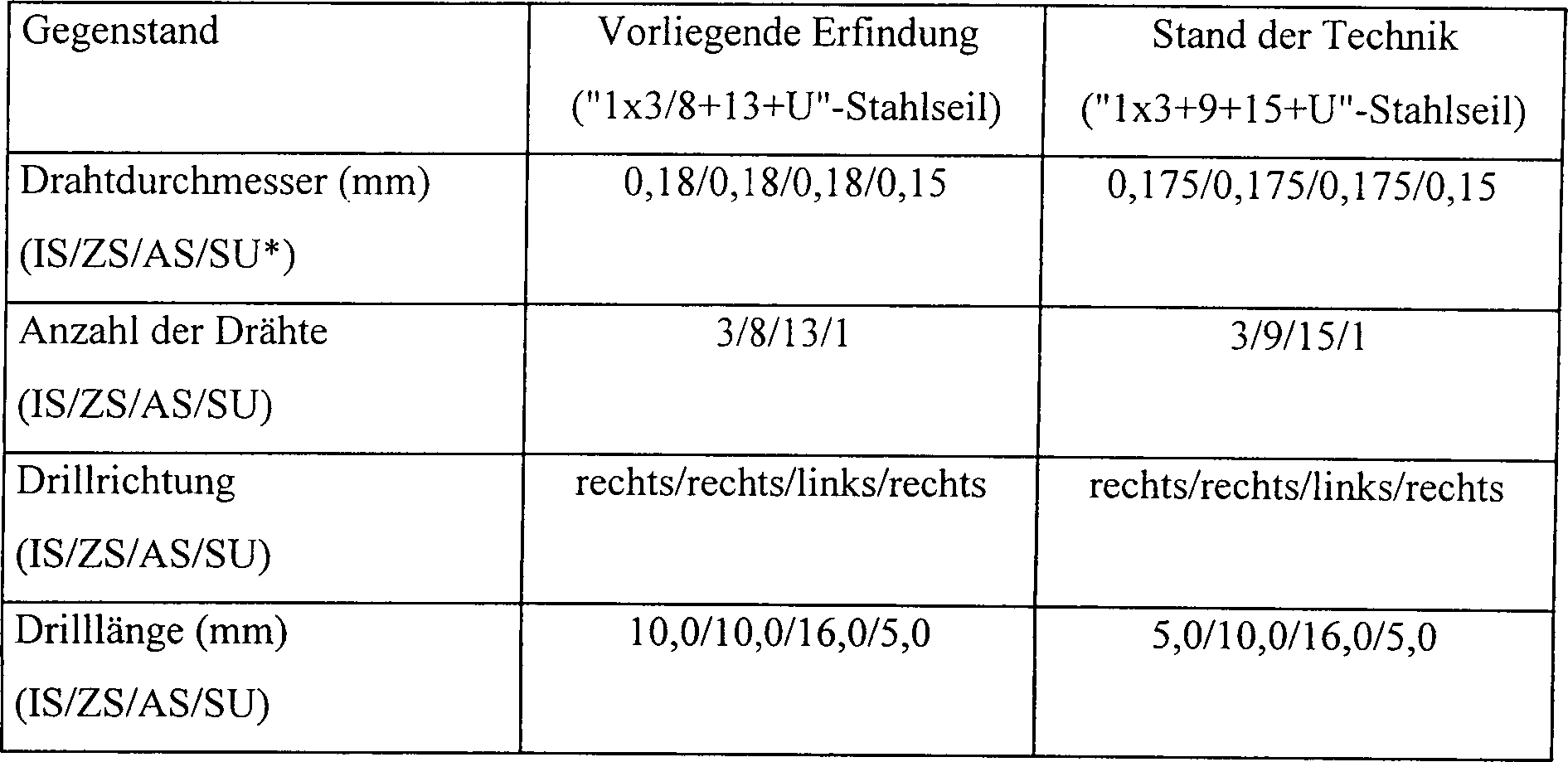
- * IS/ZS/AS/SU: Innenschicht/Zwischenschicht/Außenschichtlschraubenförmige Umhüllung
- * IS / ZS / AS / SU: Inner layer / intermediate layer / outer layer screw-shaped cover
Tabelle
2 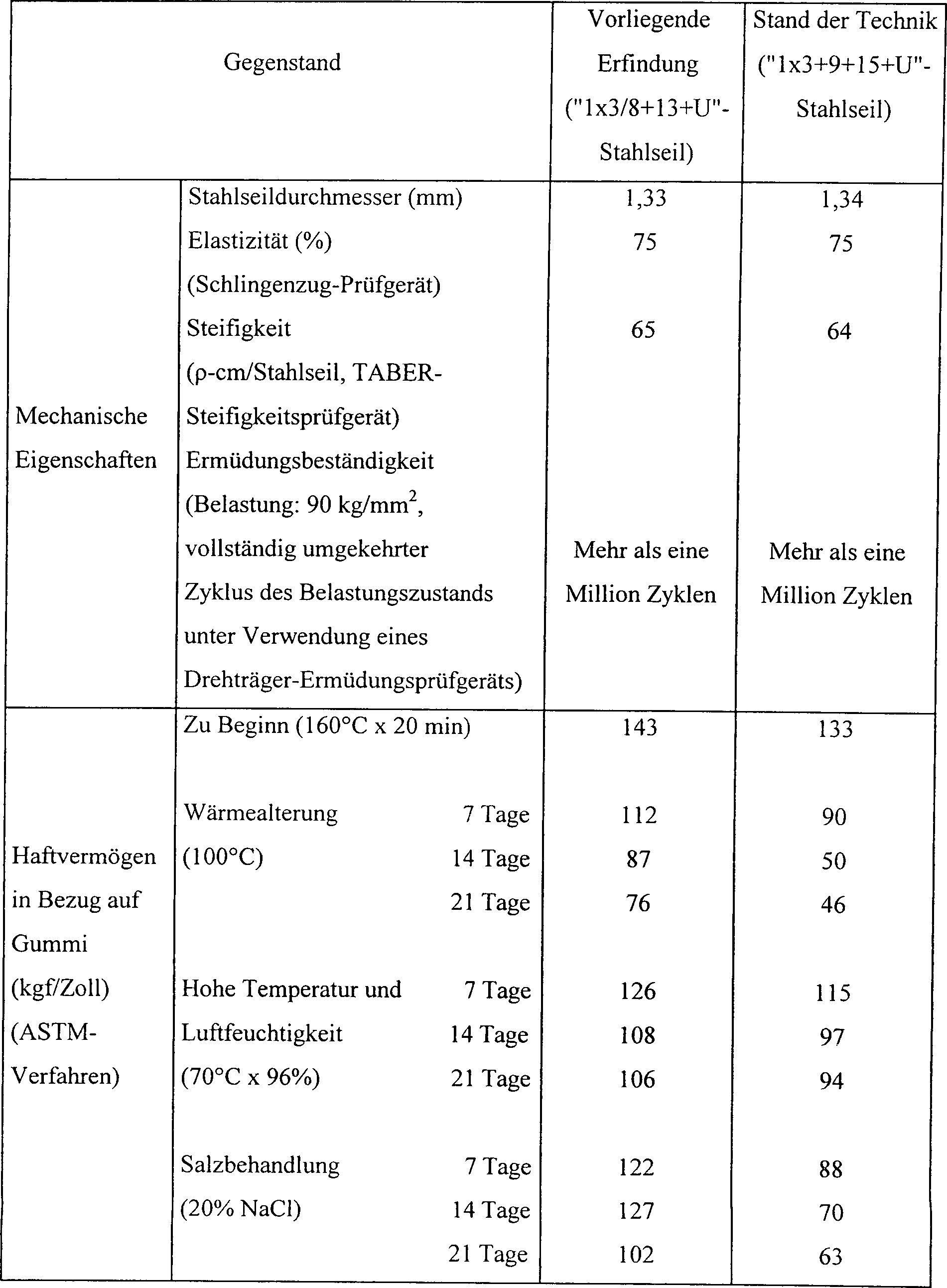
Für das erfindungsgemäße "1 × 3/8 + 13 + U"-Stahlseil 1 werden Drähte aus Kohlenstoffstahl mit einem Kohlenstoffgehalt von 0,70 bis 0,96 Gewichtsprozent verwendet. Der Kohlenstoffstahl wird gezogen. Das gezogene Produkt wird dann mit Messing beschichtet, damit dieses ein besseres Haftvermögen in Bezug auf Gummi erlangt. Zuletzt wird das erhaltene Produkt noch einmal gezogen, um die erwünschten Drahtdurchmesser zu erhalten.For the "1 × 3/8 + 13 + U "steel cable 1 become wires carbon steel with a carbon content of 0.70 to 0.96 Weight percent used. The carbon steel is pulled. The drawn Product is then coated with brass for a better one adhesiveness obtained in terms of rubber. Finally, the product obtained is still once drawn to the desired To get wire diameter.
Wie
in
Da
die Drähte
Wie aus der obigen Beschreibung hervorgeht, wird mit der vorliegenden Erfindung ein Stahlseil zur Verstärkung von Reifen und anderen Gummiprodukten geschaffen, das eine Drillkonstruktion aufweist und eine aus drei Drähten bestehende Innenschicht, eine aus acht Drähten bestehende Zwischenschicht, eine aus dreizehn Drähten bestehende Außenschicht und eine schraubenförmige Umhüllung umfasst, wobei zwischen den Drähten der Zwischenschicht und der Außenschicht Zwischenräume gebildet sind, so dass in das Stahlseil Gummi leicht eindringen kann. Aufgrund dieser Konstruktion weist das Stahlseil ein besseres Haftvermögen in Bezug auf Gummi auf, so dass die Lebensdauer von Reifen, für die das Stahlseil verwendet wird, verlängert wird. Gemäß der vorliegenden Erfindung weisen die Drähte der Innenschicht und Zwischenschicht die gleiche Drilllänge und Drillrichtung auf, so dass sie sich in annähernd vollständiger Linienberührung miteinander befinden. Daher wird die Reibkorrosion zwischen der Innenschicht und der Zwischenschicht des Stahlseils bedeutend verringert, wenn ein Reifen, für den das Stahlseil verwendet wird, wiederholt durchgebogen wird. Infolgedessen wird eine Verlängerung der Lebensdauer des Reifen erreicht.As is apparent from the above description, with the present Invention a steel cable for reinforcing tires and others Rubber products created, which has a drill construction and a from three wires existing inner layer, an intermediate layer consisting of eight wires, one of thirteen wires existing outer layer and a helical one wrapping includes, being between the wires the intermediate layer and the outer layer interspaces are formed so that rubber easily penetrate into the steel cord can. Due to this construction, the steel cable has a better one adhesiveness in terms of rubber, so that the life of tires for which the Steel rope is used, is extended. According to the present Invention have the wires the inner layer and intermediate layer the same drill length and Drill direction, so that they are in approximately complete line contact with each other are located. Therefore, the fretting corrosion between the inner layer and the intermediate layer of the steel cord significantly reduced when a tire, for the steel cable is used, is repeatedly bent. As a result, an extension reached the life of the tire.
Gemäß der vorliegenden Erfindung wird außerdem die Anzahl der Drillschritte der Innenschicht und Zwischenschicht auf einen reduziert, da die Drähte der Innenschicht und Zwischenschicht die gleiche Drilllänge und Drillrichtung aufweisen. Für diesen Drillvorgang werden bei herkömmlichen Konstruktionen zwei Bearbeitungsschritte benötigt, da für die Innenschicht und Zwischenschicht eine unterschiedliche Drilllänge verwendet wird. Daher wird eine Verringerung der Herstellungskosten erreicht.According to the present Invention will also the number of drill steps of the inner layer and intermediate layer reduced to one, because the wires the inner layer and intermediate layer the same drill length and Have drilling direction. For This drilling process becomes two in conventional designs Processing steps needed for this the inner layer and intermediate layer uses a different drill length becomes. Therefore, a reduction in manufacturing cost is achieved.
Zur Veranschaulichung wurden zwar die bevorzugten Ausführungen der vorliegenden Erfindung beschrieben; der Fachmann erkennt jedoch, dass verschiedene Modifikationen, Ergänzungen und Austauschmaßnahmen möglich sind, ohne den Rahmen dieser Erfindung, wie er in den beigefügten Ansprüchen festgelegt ist, zu verlassen.to Illustrations have been the preferred embodiments of the present invention; however, the person skilled in the art recognizes that various modifications, additions and exchanges possible are without the scope of this invention as defined in the appended claims is to leave.
Claims (2)
Applications Claiming Priority (2)
| Application Number | Priority Date | Filing Date | Title |
|---|---|---|---|
| KR1019990007249A KR100296075B1 (en) | 1999-03-05 | 1999-03-05 | A rubber and a steel cord for reinforcement of a tire with increased rubber penetration |
| KR9907249 | 1999-03-05 |
Publications (2)
| Publication Number | Publication Date |
|---|---|
| DE69923947D1 DE69923947D1 (en) | 2005-04-07 |
| DE69923947T2 true DE69923947T2 (en) | 2006-05-11 |
Family
ID=36217604
Family Applications (1)
| Application Number | Title | Priority Date | Filing Date |
|---|---|---|---|
| DE69923947T Expired - Lifetime DE69923947T2 (en) | 1999-03-05 | 1999-08-02 | Steel cable for reinforcing rubber and pneumatic tires |
Country Status (6)
| Country | Link |
|---|---|
| US (1) | US6189309B1 (en) |
| EP (1) | EP1035249B1 (en) |
| JP (1) | JP3808668B2 (en) |
| KR (1) | KR100296075B1 (en) |
| CN (1) | CN1272503C (en) |
| DE (1) | DE69923947T2 (en) |
Families Citing this family (11)
| Publication number | Priority date | Publication date | Assignee | Title |
|---|---|---|---|---|
| KR100305503B1 (en) * | 1999-06-29 | 2001-09-24 | 조충환 | A steel cord for tire and a radial tire using the same |
| KR100366069B1 (en) * | 2000-05-10 | 2002-12-26 | 홍덕스틸코드주식회사 | Steel cord for reinforcing tire and its production method |
| KR20020068861A (en) * | 2001-02-23 | 2002-08-28 | 한국타이어 주식회사 | Method for coating rubber on the steel cord of pneumatic tire |
| US7089724B2 (en) * | 2004-02-12 | 2006-08-15 | S.S. White Technologies Inc. | Flexible push/pull/rotary cable |
| KR100642993B1 (en) * | 2004-09-30 | 2006-11-10 | 한국타이어 주식회사 | Rubber penetration measurement method of steel cord topping rubber |
| KR100763762B1 (en) * | 2006-02-20 | 2007-10-04 | 주식회사 효성 | high tensile steel cord of 2 layer twisted in the different direction |
| FR2999614B1 (en) * | 2012-12-14 | 2015-08-21 | Michelin & Cie | METAL CABLE WITH HIGH PENETRABILITY LAYERS |
| KR101523429B1 (en) * | 2013-09-06 | 2015-05-27 | 한국타이어 주식회사 | Steel cord for reinforcing a tire and radial tire using the same |
| CN106661831B (en) * | 2014-07-28 | 2019-06-04 | 株式会社普利司通 | Steel cord for reinforced stock product |
| CN105735019A (en) * | 2016-02-25 | 2016-07-06 | 天津高盛钢丝绳有限公司 | Steel wire rope |
| CN113564945A (en) * | 2021-06-10 | 2021-10-29 | 南京工业职业技术大学 | Steel cord with ultrahigh strength and strong adhesive permeation performance |
Family Cites Families (7)
| Publication number | Priority date | Publication date | Assignee | Title |
|---|---|---|---|---|
| GB1582647A (en) | 1977-07-07 | 1981-01-14 | Bekaert Sa Nv | Metal cord |
| JPS63116905A (en) * | 1986-10-31 | 1988-05-21 | Toyo Tire & Rubber Co Ltd | Steel cord reinforced pneumatic tire |
| JP2659072B2 (en) * | 1988-12-16 | 1997-09-30 | 住友電気工業株式会社 | Steel cord for rubber reinforcement |
| USH1505H (en) * | 1990-12-27 | 1995-12-05 | Tokyo Rope Mfg. Co., Ltd. | Steel radial tire |
| US5285836A (en) * | 1991-01-31 | 1994-02-15 | Sumitomo Rubber Industries, Ltd. | 3+7+13 steel cord and tire including same |
| JP3540845B2 (en) * | 1994-10-21 | 2004-07-07 | 東京製綱株式会社 | Steel cord for rubber reinforcement and radial tire using the same |
| US5806296A (en) * | 1995-05-26 | 1998-09-15 | Bridgestone Metalpha Corporation | Corrosion resistant spiral steel filament and steel cord made therefrom |
-
1999
- 1999-03-05 KR KR1019990007249A patent/KR100296075B1/en not_active IP Right Cessation
- 1999-07-27 US US09/361,566 patent/US6189309B1/en not_active Expired - Lifetime
- 1999-07-30 CN CNB991112172A patent/CN1272503C/en not_active Expired - Fee Related
- 1999-08-02 DE DE69923947T patent/DE69923947T2/en not_active Expired - Lifetime
- 1999-08-02 EP EP99115288A patent/EP1035249B1/en not_active Expired - Lifetime
- 1999-08-12 JP JP22875499A patent/JP3808668B2/en not_active Expired - Fee Related
Also Published As
| Publication number | Publication date |
|---|---|
| EP1035249A2 (en) | 2000-09-13 |
| KR100296075B1 (en) | 2001-07-03 |
| DE69923947D1 (en) | 2005-04-07 |
| US6189309B1 (en) | 2001-02-20 |
| CN1266121A (en) | 2000-09-13 |
| CN1272503C (en) | 2006-08-30 |
| JP2000256977A (en) | 2000-09-19 |
| JP3808668B2 (en) | 2006-08-16 |
| EP1035249B1 (en) | 2005-03-02 |
| EP1035249A3 (en) | 2001-03-28 |
| KR20000059557A (en) | 2000-10-05 |
Similar Documents
| Publication | Publication Date | Title |
|---|---|---|
| DE60102061T2 (en) | Individually protected strands, their use in construction technology and processes for their manufacture | |
| DE69811271T2 (en) | STEEL ROPE WITH CORRUGATED ELEMENTS | |
| DE68905155T2 (en) | STEEL CABLE FOR REINFORCING RUBBER. | |
| EP0393013B1 (en) | Tensioning-bundle comprising tensioning members | |
| DE2851595C2 (en) | Ribbon cable | |
| DE3317744C2 (en) | Reinforcement cord with wrapping wire | |
| DE803800C (en) | Wire cable for metallic inserts of pneumatic tires | |
| DE69905591T2 (en) | LIFTING OR TOWING ROPE FROM MULTIPLE MATERIALS AND WITH A PLASTIC CORE | |
| DE3930496C2 (en) | ||
| DE1685846C3 (en) | Steel wire rope for the reinforcement of pneumatic tires | |
| DE2943830A1 (en) | METAL CORD | |
| DE69923947T2 (en) | Steel cable for reinforcing rubber and pneumatic tires | |
| DE112011103325T5 (en) | Electric wire | |
| AT134163B (en) | Flexible shaft and method of making the same. | |
| EP0852634B1 (en) | Process for producing a steel cord | |
| DE102016205642A1 (en) | Bend stiff cable and wiring harness | |
| WO2016138893A1 (en) | Rope and method for producing a rope | |
| DE2028243A1 (en) | tire | |
| DE68910294T2 (en) | Composite steel cord. | |
| DE69503676T2 (en) | Reinforcement for vehicle tires | |
| DE69032298T2 (en) | Steel rope for the reinforcement of elastomeric products | |
| DE10048756B4 (en) | Flexible leader | |
| AT401275B (en) | STRING SPIRAL ROPE IN PARALLEL SHOCK MACHART | |
| EP1606448B1 (en) | Method for producing a cable | |
| DE3430548C2 (en) |
Legal Events
| Date | Code | Title | Description |
|---|---|---|---|
| 8364 | No opposition during term of opposition |