Die
vorliegende Erfindung bezieht sich auf einen Luftreifen, und speziell
auf einen Radialreifen, der zu einer Kategorie von Reifen gehört, die
als sogenannte Plattlaufreifen bekannt sind, und die in einem Zustand, in
dem der innere Druck infolge eines Lochs oder dergleichen null wird
(Atmosphärendruck)
oder nahezu null wird, über
eine vorgegebene Entfernung laufen können. Vorzugsweise bezieht
sich die Erfindung auf einen Luftreifen, der ein Verhältnis von
Querschnitthöhe
zu Querschnittsbreite (oder ein Querschnittsverhältnis) von nicht weniger als
60 hat, und eine ausgezeichnete Plattlaufhaltbarkeit hat ("Plattlaufen" bedeutet das Laufen in
einem Zustand mit einem Loch), wenn er in einem Zustand mit einem
Loch mit hoher Geschwindigkeit über eine
relativ große
Entfernung gefahren wird, während
die niedrigen Kosten und die leichte Handhabung aufrechterhalten
werden.The
The present invention relates to a pneumatic tire, and more particularly
on a radial tire, which belongs to a category of tires, the
known as run flat tires, and in a state in
the internal pressure due to a hole or the like becomes zero
(Atmospheric pressure)
or almost zero, over
can run a predetermined distance. Preferably relates
the invention relates to a pneumatic tire having a ratio of
Section height
to cross-sectional width (or aspect ratio) of not less than
60, and has an excellent run-flat durability ("run flat" means running in
a state with a hole) when in a state with a hole
Hole at high speed over one
relatively large
Distance is driven while
Maintain the low cost and easy handling
become.
Der
Radialreifen vom Plattlauftyp (nachstehend als Plattlaufreifen abgekürzt) wird
hauptsächlich
bei Fahrzeugen, wie Personenwagen und dergleichen verwendet, bei
denen eine relativ kleine Belastung auf den Reifen gegeben wird.
Es wird gefordert, daß dann,
wenn der Reifen in dem platten Zustand (Zustand mit einem Loch)
ist, selbst wenn dieser Zustand plötzlich auftritt während nicht
nur der Fahrt auf Landstraßen,
sondern auch während
der Fahrt mit hoher Geschwindigkeit auf einer Schnellstraße, der
Plattlaufreifen sicher gefahren werden kann, ohne daß sich die
Lenkstabilität
des Fahrzeugs, insbesondere eines Personenwagens, wesentlich verschlechtert,
und selbst dann, wenn die Fahrt in dem Zustand mit einem Loch über eine
relativ große Entfernung
fortgesetzt wird, der Plattlaufreifen sicher und zuverlässig über eine
vorgegebene Entfernung, zum Beispiel 80-160 km, bis zu einer vorgesehenen
Stelle gefahren werden kann, ohne daß er sich von der verwendeten
Felge (zugelassenen Felge) ablöst
und Reifenbruch hervorgerufen wird.Of the
Run-flat type radial tire (hereinafter abbreviated flat tire)
mainly
used in vehicles such as passenger cars and the like at
which is given a relatively small load on the tire.
It is demanded that then,
when the tire is in the flat state (state with a hole)
even if this condition occurs suddenly while not
just driving on country roads,
but also during
driving at high speed on a highway that
Run flat tire can be safely driven without the
steering stability
of the vehicle, in particular a passenger car, substantially deteriorates,
and even if the ride in the state with a hole over one
relatively long distance
continued, the run-flat tire safely and reliably over a
predetermined distance, for example 80-160 km, to a planned
Body can be driven without it being used by the
Rim (approved rim) replaces
and tire breakage is caused.
Zu
diesem Zweck werden Plattlaufreifen mit verschiedenen Strukturen
vorgeschlagen, die oft mit einer speziell entwickelten, zugelassenen
Felge kombiniert werden. Die Reifen für solche Anwendungen werden eingeteilt
in Super-Niederquerschnittprofilreifen, die ein Querschnittverhältnis von
weniger als 60 haben, und Niederquerschnittprofilreifen, die ein
Querschnittverhältnis
von 60-80 haben, und bei denen die Querschnitthöhe relativ groß ist.To
For this purpose, runway tires with different structures are used
often proposed with a specially developed, approved
Rim combined. The tires for such applications are classified
in super-low profile tread tires having a cross-sectional ratio of
have less than 60, and low profile profile tires, the one
Aspect ratio
of 60-80, and in which the cross-sectional height is relatively large.
Was
den Super-Niederquerschnittprofilreifen betrifft, so ist ein Beispiel
eines Plattlaufreifens 20, der in den Handel gebracht wurde,
in der 5 der beigefügten
Zeichnungen wiedergegeben. Dieser Reifen 20 hat eine Struktur,
bei der eine dicke Gummiverstärkungsschicht 9,
die im Schnitt eine halbmondförmige
Form hat, auf der inneren Oberfläche
der innersten Karkassenlage 6-1 über eine Zone, die von dem
Wulstbereich 2 über den
Seitenwandbereich 3 bis zu dem Ende des Laufflächenbereichs 4 reicht,
angeordnet ist. Ein solcher Reifen wird oft an einem Hochgeschwindigkeitsfahrzeug,
wie einem Sportwagen, einem Wagen von Sporttyp oder dergleichen
angebracht.As for the super-low profile tread tire, an example of a flat tire is 20 , which was brought into the trade, in the 5 the accompanying drawings reproduced. This tire 20 has a structure in which a thick rubber reinforcing layer 9 , which has a half-moon-shaped shape on the inner surface of the innermost carcass ply 6-1 over a zone away from the bead area 2 over the sidewall area 3 to the end of the tread area 4 ranges, is arranged. Such a tire is often attached to a high-speed vehicle such as a sports car, a sports-type car or the like.
Um
den Grad der Kollabierverformung so weit wie möglich zu verringern, wenn der
Reifen 20, der die dicke Gummiverstärkungsschicht 9 hat,
in einem platten Zustand unter Belastung gefahren wird, besteht
die radiale Karkasse 6 aus zwei oder mehr Lagen, aufweisend
eine Umstülplage 6-1,
die von der Innenseite nach der Außenseite um den Wulstkern 5 geschlungen
ist, und eine herabfallende Lage 6-2, die die Umstülplage 6-1 von
der Außenseite
umhüllt,
und ein harter Versteifungsgummi 8 ist so angeordnet, daß er sich
von der äußeren Umfangsoberfläche des
Wulstkerns 5 bis zu einer Position nahe bei der maximalen
Reifenbreite erstreckt, und je nach Fall ist eine gummigetränkte Schicht
aus Kevlar-Cordfäden
oder Stahl- Cordfäden (die
Einlagen-Lage genannt wird) in einer Zone angeordnet, die von dem
Wulstbereich 2 bis zu dem Seitenwandbereich 3 reicht.To reduce the degree of collapse as much as possible when the tire 20 that the thick rubber reinforcing layer 9 has driven in a flat state under load, the radial carcass exists 6 from two or more layers, comprising a Umstülplage 6-1 going from the inside to the outside around the bead core 5 and a falling position 6-2 that the Umstülplage 6-1 enveloped by the outside, and a hard stiffening rubber 8th is disposed so as to extend from the outer peripheral surface of the bead core 5 to a position close to the maximum tire width and, as the case may be, a rubber-impregnated layer of Kevlar cords or steel cords (called a ply ply) is disposed in a zone other than the bead region 2 to the sidewall area 3 enough.
Andererseits
wird der Niederquerschnittprofilreifen, der eine relativ große Querschnitthöhe hat,
in der letzten Zeit häufig
an teuren Personenwagen mit relativ großem Hubraum angebracht. Dieser
Reifentyp kann in dem Plattlaufzustand in Verbindung mit einer Felge
gefahren werden, bei der ein Schutzelement vorgesehen ist, um den
Wulstbereich des Reifens zu dem Felgenflansch hin auf die Felge
zu schieben. Da die Höhe
des Seitenwandbereichs 3 bei dem Niederquerschnittprofilreifen
(siehe 5) wesentlich größer ist als bei dem Super-Niederquerschnittprofilreifen,
biegt sich der Seitenwandbereich 3, und daher kann die
gewünschte
Plattlaufhaltbarkeit nicht erhalten werden.On the other hand, the low-profile tread having a relatively large cross-sectional height has recently been frequently attached to expensive passenger cars having a relatively large displacement. This type of tire may be run in the run-flat condition in conjunction with a rim in which a protective member is provided to push the bead portion of the tire toward the rim flange on the rim. As the height of the sidewall area 3 at the low profile profile tire (see 5 ) is substantially larger than in the super-low profile tread tire, the sidewall region bends 3 , and therefore the desired run-flat durability can not be obtained.
Bei
dem Reifen 20, der die obige, in der 5 wiedergegebene
Bauweise hat, wird vorgeschlagen und ausgeführt, die Dicke oder die Höhe der Gummiverstärkungsschicht 9 zu
vergrößern, oder
die Härte
oder den Elastizitätsmodul
des Gummis wesentlich zu erhöhen,
um die Haltbarkeit bei dem Plattlauf-Lauf zu verbessern. Infolge
von Kostenbegrenzungen bei der Herstellung ist dies jedoch, wenn
der innere Druck plötzlich
auf null abfällt,
insbesondere ungenügend,
um die Lenkstabilität
des Fahrzeugs bei der Fahrt mit hoher Geschwindigkeit sicherzustellen,
und bei der Fortsetzung der Fahrt in dem Plattlaufzustand ist auch
die Haltbarkeit ungenügend.
Daher wird gewünscht,
Reifen zu entwickeln, bei denen die obigen Eigenschaften aufrechterhalten werden,
und die Plattlaufhaltbarkeit bis auf ein Niveau, bei dem bei der
praktischen Verwendung kein Problem hervorgerufen wird, verbessert
wird.At the tire 20 who is the above, in the 5 has been proposed, and proposed, the thickness or the height of the rubber reinforcing layer 9 to increase or substantially increase the hardness or the modulus of elasticity of the rubber to improve the durability in the run-flat run. However, as a result of production cost constraints, when the internal pressure suddenly drops to zero, this is particularly insufficient to improve the steering stability of the vehicle when traveling at high speed durability and in the continuation of the run in the run-flat condition also the durability is insufficient. Therefore, it is desired to develop tires in which the above characteristics are maintained, and the run-flat durability is improved to a level where no problem is caused in practical use.
In
dem Fall, in dem das Schutzelement bei der Felge eingebaut wird,
ergibt sich erstens ein Problem bei der sogenannten Felgenmontage,
weil es nicht leicht ist, den Reifen auf der Felge anzubringen.
Zweitens ist es unvermeidlich, daß das Gewicht der Reifen-Felgen-Einheit
wesentlich erhöht
wird, was eine signifikante Zunahme der ungefederten Masse bei dem
Fahrzeug bewirkt, und daher wird der Fahrkomfort des Fahrzeugs bezüglich Vibrationen
wesentlich verschlechtert, so daß der Reifen als Reifen für einen
teuren Personenwagen ungeeignet ist.In
in the case where the protective element is installed in the rim,
First, there is a problem with the so-called rim assembly,
because it is not easy to attach the tire to the rim.
Second, it is inevitable that the weight of the tire-rim unit
significantly increased
which is a significant increase in unsprung mass in the
Vehicle causes, and therefore the ride comfort of the vehicle with respect to vibrations
significantly worsened, so that the tire as a tire for a
expensive passenger car is unsuitable.
Die
Erfinder der vorliegenden Erfindung haben die Position und die Ursache
der Reifenstörung,
die bei Zeitserien während
der Plattlauf-Fahrt des in der 5 wiedergegebenen
Reifens 20 bezüglich
der Plattlaufhaltbarkeit erzeugt wird, gründlich untersucht, und bestätigt, daß die Störungsstelle,
die bei dem Reifen am raschesten erzeugt wird, ein Randbereich bei
dem Gürtel 7 in
dem γ-Gebiet
(siehe 5) ist, und eine solche Störungsstelle dann in aufeinanderfolgender
Weise eine Störungsstelle
der Gummiverstärkungsschicht 9 in dem β-Gebiet des
Seitenwandbereichs 3 (siehe 5) und eine
Störungsstelle
bei dem Versteifungsgummi 8 in dem α-Gebiet des Wulstbereichs 2 (siehe 5)
hervorruft. Daher haben die Erfinder bereits einen Luftreifen 21A vorgeschlagen,
der insbesondere ein Querschnittverhältnis von nicht weniger als
60 hat, und bei dem ein Kissengummi 10, wie in der 6 der
Zeichnungen gezeigt, zwischen dem Randbereich des Gürtels 7 und der äußersten
Karkassenlage 6-2 angeordnet ist, und der tan δ des Kissengummis 10 nicht
größer ist
als derjenige des Beschichtungsgummis für die Cordfäden der Karkassenlage 6,
wie in der japanischen Patentanmeldung 10-121422 beschrieben. Dieser
Reifen 21A beweist, daß eine
bemerkenswerte Verbesserung der Haltbarkeit in dem Randbereich des
Gürtels 7 während der
Plattlauf-Fahrt in vorteilhafter Weise verwirklicht werden kann,
um eine ausgezeichnete Plattlaufhaltbarkeit zu erreichen.The inventors of the present invention have the position and the cause of the tire disturbance involved in time series during the run-flat driving of the in the 5 reproduced tire 20 in terms of runflat durability is thoroughly investigated, and confirms that the trouble spot most rapidly generated in the tire is an edge portion of the belt 7 in the γ-region (see 5 ), and then such a disturbance location is in succession a point of failure of the rubber reinforcing layer 9 in the β-region of the sidewall region 3 (please refer 5 ) and a malfunction in the stiffening rubber 8th in the α-region of the bead area 2 (please refer 5 ). Therefore, the inventors already have a pneumatic tire 21A proposed, in particular, has a cross-sectional ratio of not less than 60, and wherein a cushion rubber 10 , like in the 6 shown in the drawings, between the edge region of the belt 7 and the outermost carcass ply 6-2 is arranged, and the tan δ of the cushion rubber 10 is not larger than that of the coating rubber for the cords of the carcass ply 6 as described in Japanese Patent Application 10-121422. This tire 21A proves that a remarkable improvement in durability in the edge region of the belt 7 during the run-flat ride can be advantageously realized to achieve an excellent run-flat durability.
Es
wird jedoch gefordert, die Plattlaushaltbarkeit weiter so zu verbessern,
daß es
möglich
ist, über
mindestens eine Entfernung von 80-160 km zu fahren, wie oben erwähnt wurde,
bei Fortsetzung der Fahrt bei einem oberen Niveau der Grenzgeschwindigkeit
in dem Plattlaufzustand auf einer Schnellstraße, selbst bei einem Luftreifen,
der ein Querschnittsverhältnis
von nicht weniger als 60 hat. Bei einer so harten Bedingung ist es
erforderlich, die Plattlaufhaltbarkeit bei dem obenerwähnten Luftreifen 21A weiter
zu verbessern.However, it is demanded to further improve the flatness durability such that it is possible to travel over at least a distance of 80-160 km, as mentioned above, if traveling at an upper level of the limit speed in the run-flat state on a freeway even in a pneumatic tire having an aspect ratio of not less than 60. Under such a severe condition, the runflat durability in the above-mentioned pneumatic tire is required 21A continue to improve.
Ein
Ziel der Erfindung ist daher, einen Luftreifen zu verwirklichen,
der insbesondere ein Querschnittverhältnis von nicht weniger als
60 hat, der bei vernünftigen
Kosten hergestellt werden kann, der eine leichte Handhabbarkeit
bei der Felgenmontage und dergleichen hat, und dessen Fahrkomfort
innerhalb eines annehmbaren Bereichs liegt, ohne daß sich eine
Unbequemlichkeit bei dem Herstellungsschritt zum Aufbringen der
herkömmlichen
dicken Gummiverstärkungsschicht
ergibt, und der eine sichere Fahrt des Fahrzeugs, wie eines Personenwagens
oder dergleichen sicherstellt, selbst wenn die Luft infolge eines
Lochs oder dergleichen rasch entweicht, und der funktioniert, selbst
wenn die Fahrt mit hoher Geschwindigkeit auf einer Schnellstraße bei oder
nahe bei einer Grenzgeschwindigkeit während einer langen Zeit fortgesetzt
wird, und der eine ausgezeichnete Plattlaufhaltbarkeit entwickeln
kann.One
The aim of the invention is therefore to realize a pneumatic tire,
in particular a cross-sectional ratio of not less than
60, who at reasonable
Cost can be produced, which is easy to handle
in rim mounting and the like, and its ride comfort
within an acceptable range, without any
Inconvenience in the manufacturing step for applying the
usual
thick rubber reinforcing layer
yields, and the safe driving of the vehicle, such as a passenger car
or the like, even if the air due to a
Holes or the like escapes quickly, and that works, even
when driving at high speed on a highway at or
continued near a limit speed for a long time
and that will develop an excellent runtime durability
can.
Außerdem wird
auf das Dokument US-A-4287924 hingewiesen, in dem ein Reifen beschrieben
wird, der die Merkmale des vorkennzeichnenden Teils des Patentanspruchs
1 hat.In addition, will
to the document US-A-4287924, in which a tire is described
which is the features of the precharacterizing part of claim
1 has.
Gemäß der vorliegenden
Erfindung wird ein Luftreifen verwirklicht, aufweisend eine radiale
Karkasse, die sich zwischen zwei in einen jeweiligen Wulstbereich
eingebetteten Wulstkernen erstreckt, um zwei Seitenwandbereiche
und einen Laufflächenbereich
zu verstärken,
und die aus einer oder mehr gummigetränkten Cordlagen besteht, einen
Gürtel,
der auf der äußeren Umfangsoberfläche der
Karkasse angeordnet ist, um den Laufflächenbereich zu verstärken, einen
Wulstfüllergummi,
der sich spitz zulaufend von einer Position unmittelbar über dem
Wulstkern zu dem Ende des Laufflächenbereichs
hin erstreckt, und eine Gummiverstärkungsschicht, die auf der
inneren Oberfläche
der innersten Karkassenlage von einer nahe bei dem Wulstkern in
dem Wulstbereich gelegenen Position bis zu einer nahe bei dem Ende
des Laufflächenbereichs
gelegenen Position angeordnet ist und im wesentlichen eine halbmondförmige Form
im Schnitt hat, dadurch gekennzeichnet, daß mindestens eine Gummischutzfolie,
die relativ weich ist, angeordnet ist zwischen dem Wulstfüllergummi
und der ihn umgebenden Karkassenlage und/oder zwischen der Gummiverstärkungsschicht
und der am nächsten
dabei gelegenen Karkassenlage, und in einer Zone, die sich von einer
Position eines Liniensegments, das parallel zu der axialen Rotationslinie
des Reifens ist und durch das äußere Ende
des Wulstfüllergummis
hindurchgeht, in der radialen Richtung des Reifens nach innen erstreckt.According to the present
Invention, a pneumatic tire is realized, comprising a radial
Carcass extending between two into a respective bead area
embedded bead cores extends to two sidewall areas
and a tread area
to reinforce
and which consists of one or more rubber-soaked Cordlagen, a
Belt,
on the outer peripheral surface of the
Carcass is arranged to reinforce the tread area, a
bead filler,
tapering from a position immediately above the
Bead core to the end of the tread area
extends, and a rubber reinforcing layer on the
inner surface
the innermost carcass ply of one near the bead core in
the bead area up to one near the end
of the tread area
located position and is substantially a crescent shape
on average, characterized in that at least one rubber protective film,
which is relatively soft, is disposed between the bead filler rubber
and the carcass ply surrounding it and / or between the rubber reinforcing layer
and the closest
carcass ply, and in a zone extending from one
Position of a line segment parallel to the axial rotation line
of the tire is and through the outer end
the bead filler rubber
passes inwardly in the radial direction of the tire.
Bei
einer bevorzugten Ausführungsform
der Erfindung ist mindestens eine Lage der Karkasse eine Umstülplage,
die von der Innenseite nach der Außenseite des Reifens um den
Wulstkern geschlungen ist, und aus einem sich toroidförmig erstreckenden
Hauptkörper
und einem Umstülpbereich
besteht.at
a preferred embodiment
invention, at least one layer of the carcass is a turn-up ply,
from the inside to the outside of the tire around the
Bead core is wound, and from a toroidally extending
main body
and an everting area
consists.
Wenn
die Karkasse aus zwei oder mehr Lagen besteht, hat sie außerdem eine
sogenannte Aufwärts/Abwärts-Lage-Struktur,
bestehend aus einer Umstülplage,
die einen Umstülpbereich
hat, wie oben erwähnt,
und einer herabfallenden Lage, die die Umstülplage einschließlich des
Umstülpbereichs
von der Außenseite
umhüllt.If
The carcass consists of two or more layers, it also has one
so-called up / down position structure,
consisting of a Umstülplage,
the one everting area
has, as mentioned above,
and a falling position, which the Umstülplage including the
turnup
from the outside
envelops.
Bei
einer weiteren bevorzugten Ausführungsform
der Erfindung ist in einem radialen Schnitt einer Reifen-Felgen-Einheit,
wenn der Reifen auf einer empfohlenen Felge angebracht ist, und
auf einen Druck, der 15% des maximalen Luftdrucks entspricht, aufgeblasen
ist, die Gummischutzfolie auf den beiden Seiten einer geraden Linie
vorhanden, die von dem Krümmungsmittelpunkt
des Flansches der empfohlenen Felge unter einem Neigungswinkel von
60° bezüglich eines
Liniensegments, das von dem Krümmungsmittelpunkt
parallel zu einer axialen Rotationslinie des Reifens nach der Innenseite
des Reifens gezogen ist, in der radialen Richtung des Reifens nach
außen
gezogen ist.at
a further preferred embodiment
the invention is in a radial section of a tire-rim unit,
if the tire is mounted on a recommended rim, and
inflated to a pressure corresponding to 15% of the maximum air pressure
is the rubber protective film on the two sides of a straight line
present from the center of curvature
the flange of the recommended rim at an angle of inclination of
60 ° with respect to one
Line segment, that of the center of curvature
parallel to an axial rotation line of the tire to the inside
of the tire, in the radial direction of the tire
Outside
is drawn.
Der
hier verwendete Ausdruck "maximaler
Luftdruck" bedeutet
einen maximalen Luftdruck (Luftdruck, der einer maximalen Last entspricht),
der in der "General
Information" der "European Tire and
Rim Technical Organization" (nachstehend
als "ETRTO-Standards" abgekürzt) angegeben
ist, und der hier verwendete Ausdruck "empfohlene Felge" bedeutet eine darin empfohlene Felge.
Als der maximale Luftdruck und die empfohlene Felge werden speziell
numerische Werte und Felgengrößen verwendet,
die in der für
jede Reifenart in den ETRTO-Standards erstellten "LOAD/INFLATION PRESSURE
TABLE" und "RIM CONTOURS TABLE" angegeben sind.
Außerdem
ist die empfohlene Felge eine Felge, die in den Listen der "RIM CONTOURS TABLE" unterstrichen ist.Of the
used herein "maximum
Air pressure "means
a maximum air pressure (air pressure corresponding to a maximum load),
the one in the "General
Information "the" European Tire and
Rim Technical Organization "(below
abbreviated as "ETRTO standards")
and the term "recommended rim" as used herein means a recommended rim.
As the maximum air pressure and the recommended rim are special
uses numerical values and rim sizes,
in the for
Each tire type in the ETRTO standards created "LOAD / INFLATION PRESSURE
TABLE "and" RIM CONTOURS TABLE "are specified.
Furthermore
the recommended rim is a rim that is underlined in the lists of "RIM CONTOURS TABLE".
Außerdem bedeutet
die Formulierung "der
Reifen wird auf der empfohlenen Felge angebracht und auf einen Luftdruck
aufgeblasen, der 15% des maximalen Luftdrucks entspricht", daß der auf
der empfohlenen Felge angebrachte Reifen einmal auf einen Luftdruck
aufgeblasen wird, der nicht niedriger als der maximale Luftdruck
ist, um den Reifen an die empfohlene Felge anzupassen, und danach
die Luft bis auf einen niedrigen Druck, der 15% des maximalen Luftdrucks
entspricht, abgelassen wird, oder die Luft einmal bis auf einen
inneren Druck von Null abgelassen wird und der Reifen dann wieder
auf einen niedrigen Druck, der 15% des maximalen Luftdrucks entspricht,
aufgeblasen wird, während
der genügend
angepaßte
Zustand aufrechterhalten wird.It also means
the wording "the
Tire is mounted on the recommended rim and on an air pressure
inflated, which corresponds to 15% of the maximum air pressure "that on
the recommended rim once attached tire to an air pressure
is inflated, not lower than the maximum air pressure
is to adapt the tire to the recommended rim, and afterwards
the air down to a low pressure, which is 15% of the maximum air pressure
equals, is drained, or the air once except for one
inner pressure is drained from zero and then the tire again
to a low pressure equal to 15% of the maximum air pressure,
is inflated while
the enough
adapted
Condition is maintained.
Bei
einer weiteren bevorzugten Ausführungsform
der Erfindung ist die Gummischutzfolie zwischen den Liniensegmenten
vorhanden, die parallel zu der axialen Rotationslinie des Reifens
sind, und durch das in der radialen Richtung des Reifens äußere Ende
des Wulstfüllergummis
bzw. das in der radialen Richtung des Reifens innere Ende der Gummiverstärkungsschicht
hindurchgehen.at
a further preferred embodiment
The invention is the rubber protective film between the line segments
present, parallel to the axial rotation line of the tire
are, and by in the radial direction of the tire outer end
the bead filler rubber
or the inner end of the rubber reinforcing layer in the radial direction of the tire
pass.
Bei
noch einer weiteren bevorzugten Ausführungsform der Erfindung ist
dann, wenn die Gummischutzfolie längs des Umstülpbereichs
der Karkassenlage zwischen dem Umstülpbereich und dem Wulstfüllergummi
angeordnet ist, die Höhe
Ha des in der radialen Richtung des Reifens äußeren Endes der Gummischutzfolie,
gemessen ab dem in der radialen Richtung des Reifens äußersten
Ende des Wulstkerns, nicht größer ist
als die zweifache Höhe
Hb des Schnittpunktes zwischen der geraden Linie, die von dem Krümmungsmittelpunkt
des Flansches der empfohlenen Felge in der radialen Richtung nach
außen
gezogen ist, unter einem Neigungswinkel von 60° bezüglich eines Liniensegments,
das von dem Krümmungsmittelpunkt
parallel zu der axialen Rotationslinie des Reifens nach der Innenseite
des Reifens gezogen ist, und der äußeren Oberfläche der äußersten
Karkassenlage, gemessen nach der gleichen Methode wie oben.at
Yet another preferred embodiment of the invention
then, when the rubber protective film along the everting area
the carcass ply between the eversion area and the bead filler rubber
is arranged, the height
Ha in the radial direction of the tire outer end of the rubber protective film,
measured from the outermost in the radial direction of the tire
End of the bead core, not bigger
as twice the height
Hb of the intersection between the straight line, that of the center of curvature
of the flange of the recommended rim in the radial direction
Outside
is pulled, at a tilt angle of 60 ° with respect to a line segment,
that from the center of curvature
parallel to the axial line of rotation of the tire towards the inside
of the tire is pulled, and the outer surface of the outermost
Carcass ply measured by the same method as above.
Was
die Eigenschaften der Gummischutzfolie betrifft, so hat die Gummischutzfolie
vorzugsweise einen 50%-Elastizitätsmodul,
der gleich dem 0,30-0,84-fachen 50%-Elastizitätsmodul des Gummiverstärkungsgummis
ist, und einen tan δ bei
25°C von
0,04-0,11.What
As far as the properties of the rubber protective film are concerned, the rubber protective film has
preferably a 50% modulus of elasticity,
equal to 0.30-0.84 times the 50% modulus of the rubber reinforcement rubber
is, and a tan δ at
25 ° C of
From 0.04 to 0.11.
Der
Wert des 50%-Elastizitätsmoduls
wird mittels einer Berechnungsformel bestimmt, die unter "tensile stress" in dem Inhaltsverzeichnis
von "Tensile test
method in the cured rubber" von
JIS K 6251-1993
angegeben ist. Außerdem
wird der Wert von tan δ dadurch
bestimmt, daß eine
Art der Verformung wie die Zugverformung berechnet wird gemäß "A case of the waveshape
in the load and the waveshape in the flexure" unter "(1) non-resonating methods", angegeben in "Method for testing
dynamic nature in the cured rubber" von JIS K6394-1995. Außerdem wird
der Wert von tan δ bei
dem tatsächlichen
Test unter Testbedingungen bestimmt, bei denen die anfängliche
Zuglast 160 g, die dynamische Dehnung 1,0% und die Frequenz 52 Hz
ist.The value of the 50% modulus is determined by a calculation formula given under "tensile stress" in the table of contents of "Tensile test method in the cured rubber" of JIS K 6251-1993. In addition, the value of tan δ is determined by calculating a kind of deformation such as the tensile strain according to "A case of the waveshape in the load and the waveshape in the flexure" under "(1) non-resonating methods" shown in FIG "Method for testing dynamic nature in the cured rubber" of JIS K6394-1995. In addition, the value of tan δ in the actual test will be under test conditions where the initial tensile load is 160 g, the dynamic strain is 1.0% and the frequency is 52 Hz.
Vorzugsweise
hat die Gummischutzfolie eine Dicke von 0,4-4,0 mm. Streng genommen
hat die Gummischutzfolie noch besser eine Dicke von 0,6-4,0 mm,
wenn sie zwischen dem Wulstfüllergummi
und dem Hauptkörper
der Karkassenlage und/oder zwischen der Gummiverstärkungsschicht
und dem Hauptkörper
der Karkassenlage angeordnet wird, und eine Dicke von 0,4-4,0 mm,
wenn sie längs
des Umstülpbereichs
der Karkassenlage zwischen dem Umstülpbereich und dem Wulstfüllergummi
angeordnet wird.Preferably
The rubber protective film has a thickness of 0.4-4.0 mm. Strictly speaking
the rubber protective film has even better a thickness of 0.6-4.0 mm,
if they are between the bead filler rubber
and the main body
the carcass ply and / or between the rubber reinforcing layer
and the main body
the carcass ply is placed, and a thickness of 0.4-4.0 mm,
if they are longitudinal
of the eversion area
the carcass ply between the eversion area and the bead filler rubber
is arranged.
Die
Erfindung wird nun weiter beschrieben unter Bezugnahme auf die beigefügten Zeichnungen,
die Folgendes darstellen:The
The invention will be further described with reference to the accompanying drawings, in which
represent the following:
Die 1 ist
eine schematische Schnittansicht der linken Hälfte einer Einheit aus einer
ersten Ausführungsform
des erfindungsgemäßen Luftreifens
und einer empfohlenen Felge.The 1 is a schematic sectional view of the left half of a unit of a first embodiment of the pneumatic tire according to the invention and a recommended rim.
Die 2 ist
eine schematische Schnittansicht der linken Hälfte einer Einheit aus einer
zweiten Ausführungsform
des erfindungsgemäßen Luftreifens
und einer empfohlenen Felge.The 2 is a schematic sectional view of the left half of a unit of a second embodiment of the pneumatic tire according to the invention and a recommended rim.
Die 3 ist
eine schematische Schnittansicht der linken Hälfte einer Einheit aus einer
dritten Ausführungsform
des erfindungsgemäßen Reifens
und einer empfohlenen Felge.The 3 is a schematic sectional view of the left half of a unit of a third embodiment of the tire according to the invention and a recommended rim.
Die 4 ist
eine schematische vergrößerte Schnittansicht
eines Hauptteils der in der 1 wiedergegebenen
Reifen-Felge-Einheit.The 4 is a schematic enlarged sectional view of a main part of the in the 1 reproduced tire-rim unit.
Die 5 ist
eine schematische Schnittansicht der linken Hälfte eines herkömmlichen
Reifens.The 5 Fig. 10 is a schematic sectional view of the left half of a conventional tire.
Die 6 ist
eine schematische Schnittansicht der linken Hälfte eines Vergleichsluftreifens.The 6 is a schematic sectional view of the left half of a comparison pneumatic tire.
Die 7 ist
eine schematische Schnittansicht einer Hälfte einer Einheit aus einem
weiteren Vergleichsreifen und einer empfohlenen Felge während des
Laufs in einem Plattlaufzustand.The 7 Fig. 12 is a schematic sectional view of a half of a unit of another comparative tire and a recommended rim during running in a run-flat state.
Die 8 ist
ein Diagramm, das den Zusammenhang zwischen der Laufentfernung auf
einer Trommel in einem Plattlaufzustand und dem tan δ wiedergibt.The 8th Fig. 12 is a diagram showing the relationship between the running distance on a drum in a run-flat state and the tan δ.
Die 9 ist
ein Diagramm, das den Zusammenhang zwischen der Laufentfernung auf
einer Trommel in einem Plattlaufzustand und dem 50%-Elastizitätsmodul
einer Gummischutzschicht für
eine Gummiverstärkungsschicht
wiedergibt.The 9 Fig. 15 is a diagram showing the relationship between the running distance on a drum in a run-flat state and the 50% modulus of a rubber protective layer for a rubber reinforcing layer.
Die 10 ist
ein Diagramm, das den Zusammenhang zwischen der Laufentfernung auf
einer Trommel in einem Plattlaufzustand und der Dicke der Gummischutzfolien 11, 13 wiedergibt.The 10 Fig. 12 is a diagram showing the relationship between the running distance on a drum in a run-flat state and the thickness of the rubber protective films 11 . 13 reproduces.
Die 11 ist
ein Diagramm, das den Zusammenhang zwischen der Laufentfernung auf
einer Trommel in einem Plattlaufzustand und der Dicke einer Gummischutzfolie 12 wiedergibt.The 11 Fig. 12 is a diagram showing the relationship between the running distance on a drum in a run-flat state and the thickness of a rubber protective film 12 reproduces.
Verschiedene
Ausführungsformen
der Erfindung werden nun unter Bezugnahme auf die 1-4 beschrieben.Various embodiments of the invention will now be described with reference to FIGS 1 - 4 described.
In
der 1 ist ein Schnitt der linken Hälfte einer Einheit wiedergegeben,
bei der eine erste Ausführungsform
des erfindungsgemäßen Luftreifens
auf einer empfohlenen Felge angebracht ist und auf einen niedrigen
inneren Druck aufgeblasen ist, und in den 2 und 3 sind
weitere Einheiten wiedergegeben, bei denen die zweite bzw. dritte
Ausführungsform
des erfindungsgemäßen Luftreifens
auf einer empfohlenen Felge angebracht ist und auf einen niedrigen
Druck aufgeblasen ist. In der 4 ist eine
schematische vergrößerte Schnittansicht
eines Hauptteils um einen Wulstbereich des in der 1 dargestellten
Reifens wiedergegeben.In the 1 is a section of the left half of a unit reproduced, in which a first embodiment of the pneumatic tire according to the invention is mounted on a recommended rim and is inflated to a low internal pressure, and in the 2 and 3 Further units are shown, in which the second or third embodiment of the pneumatic tire according to the invention is mounted on a recommended rim and is inflated to a low pressure. In the 4 FIG. 12 is a schematic enlarged sectional view of a main part around a bead portion of FIG 1 illustrated tire reproduced.
Die
in den 1–3 wiedergegebenen
Luftreifen 1 sind Luftreifen für Personenwagen, die ein Querschnittverhältnis von
nicht weniger als 60 haben. Der Reifen 1 weist auf zwei
Wulstbereiche 2 (nur eine Seite davon ist wiedergegeben),
zwei Seitenwandbereiche 3 (nur eine Seite davon ist wiedergegeben),
einen Laufflächenbereich 4,
der mit den beiden Seitenwandbereichen 3 verbunden ist,
eine radiale Karkasse 6, die sich zwischen zwei in die
jeweiligen Wulstbereiche 2 eingebetteten Wulstkernen 5 erstreckt,
um die Bereiche 1, 2, 3 zu verstärken, und
aus einer oder mehr gummigetränkten
Cordlagen (zwei Cordlagen bei der dargestellten Ausführungsform)
besteht, und einen Gürtel 7,
der auf dem äußeren Umfang
der Karkasse 6 angeordnet ist, um den Laufflächenbereich 4 zu
verstärken.The in the 1 - 3 reproduced pneumatic tires 1 are pneumatic tires for passenger cars, which have a cross-sectional ratio of not less than 60. The mature 1 points to two bead areas 2 (only one side of it is reproduced), two sidewall areas 3 (only one side of it is reproduced), a tread area 4 , with the two sidewall areas 3 connected, a radial carcass 6 extending between two into the respective bead areas 2 embedded bead cores 5 extends to the areas 1 . 2 . 3 to reinforce, and from one or more rubber-soaked Cordlagen (two Cordlagen in the Darge embodiment), and a belt 7 standing on the outer circumference of the carcass 6 is arranged to the tread area 4 to reinforce.
Die
Karkasse 6 weist bei den dargestellten Ausführungsformen
auf eine Umstülplage 6-1,
die von der Innenseite nach der Außenseite des Reifens um den
Wulstkern 5 geschlungen ist, um den Umstülpbereich 6-1u zu
bilden, und eine herabfallende Lage 6-2, die den Hauptkörper 6-1b und
den Umstülpbereich 6-1u der Umstülplage 6-1 von
der Außenseite
umhüllt
und ein Ende in der Nähe
des Wulstkerns 5 hat. Bei der Karkasse 6 der dargestellten
Ausführungsformen
bildet die Umstülplage 6-1 die
innerste Karkassenlage.The carcass 6 indicates in the illustrated embodiments, a Umstülplage 6-1 running from the inside to the outside of the tire around the bead core 5 is looped around the eversion area 6-1u to form, and a falling position 6-2 that the main body 6-1b and the eversion area 6-1u the Umstülplage 6-1 enveloped by the outside and one end near the bead core 5 Has. At the carcass 6 The illustrated embodiments forms the Umstülplage 6-1 the innermost carcass ply.
Sowohl
die Umstülplage 6-1,
als auch die herabfallende Lage 6-2, die die Karkasse 6 bilden,
ist eine gummigetränkte
Lage mit radialer Cordfadenanordnung, bei der ein Cordfaden aus
einer organischen Faser, wie ein Polyester-Cordfaden, ein Reyon-Cordfaden,
ein Nylon-Cordfaden oder dergleichen als ein Lagencordfaden verwendet
wird. Außerdem
kann die Karkasse 6 aus zwei oder mehr Umstülplagen 6-1 und
einer oder mehr herabfallenden Lagen 6-2, oder nur aus
der Umstülplage 6-1 bestehen.Both the Umstülplage 6-1 , as well as the falling position 6-2 that the carcass 6 is a rubber-soaked radial cord arrangement sheet using an organic fiber cord such as a polyester cord, a rayon cord, a nylon cord or the like as a ply cord. In addition, the carcass can 6 from two or more Umstülplagen 6-1 and one or more falling layers 6-2 , or just from the Umstülplage 6-1 consist.
Der
Gürtel 7 besteht
aus zwei oder mehr Cordschichten, vorzugsweise zwei schrägen Cordschichten bei
der dargestellten Ausführungsform,
möglichst
zwei schrägen
Stahlcordschichten 7-1 und 7-2, und er kann eine
Cordschicht aus einer organischen Faser aufweisen, die die zwei
schrägen
Stahlcordschichten auf ihrem äußeren Umfang
umhüllt,
wie in der 1 durch eine gestrichelte Linie
wiedergegeben ist, zum Beispiel eine spiralförmig gewickelte Schicht 7-3 aus
Nylon-6,6-Cordfaden oder Kevlar-Cordfaden. Die schrägen Stahlcordschichten
haben eine Struktur, bei der die Stahlcordfäden dieser Schichten sich bezüglich der Äquatorebene E
des Reifens überkreuzen.
Bei der dargestellten Ausführungsform
ist die Breite der an die Karkasse 6 angrenzenden Stahlcordschicht 7-1 größer als
die Breite der auf der Außenseite
der Stahlcordschicht 7-1 gelegenen Stahlcordschicht 7-2.The belt 7 consists of two or more cord layers, preferably two oblique cord layers in the illustrated embodiment, preferably two oblique steel cord layers 7-1 and 7-2 , and it may have a cord layer of organic fiber surrounding the two oblique steel cord layers on its outer circumference, as in FIG 1 is represented by a dashed line, for example, a spirally wound layer 7-3 Nylon 6,6 cord or Kevlar cord. The oblique steel cord layers have a structure in which the steel cords of these layers cross each other with respect to the equatorial plane E of the tire. In the illustrated embodiment, the width of the carcass 6 adjacent steel cord layer 7-1 greater than the width of the outside of the steel cord layer 7-1 located steel cord layer 7-2 ,
Der
Reifen 1 weist außerdem
einen harten Wulstfüllergummi 8 auf,
der sich von der äußeren Umfangsfläche des
Wulstkerns 5 zu einem Rand des Laufflächenbereichs 4 hin
erstreckt, und der mit der Umstülplage 6-1 einschließlich des
Umstülpbereichs 6-1u,
und der herabfallenden Lage 6-2 bedeckt ist.The mature 1 also has a hard bead filler rubber 8th extending from the outer peripheral surface of the bead core 5 to an edge of the tread area 4 extends, and with the Umstülplage 6-1 including the eversion area 6-1u , and the falling position 6-2 is covered.
Außerdem weist
der Reifen 1 eine mit dem Plattlaufreifen untrennbar verbundene
Gummiverstärkungsschicht 9 auf
(nur eine Seite davon ist wiedergegeben), die im Schnitt eine halbmondförmige Form
hat, und die sich von einer Position nahe bei dem Wulstkern 5 in
dem Wulstbereich 2 bis zu einer Position nahe bei dem Rand
des Laufflächenbereichs 4 auf
der inneren Oberfläche
der innersten Lage der Karkasse 6, das heißt, der
Umstülplage 6-1 in
der 1 erstreckt. Die Gummiverstärkungsschicht 9 besteht
aus einem harten Gummi, um das gesamte Gewicht des fahrenden Fahrzeugs
stabil zu tragen, selbst wenn der innere Druck des Reifens null
ist, und um zu verhindern, daß sich
der Reifen 1 von der Felge ablöst, um den Bruch des Reifens
zu verhindern, und um die Laufstabilität aufrechtzuerhalten, selbst
bei einem großen
Loch während
der Fahrt mit hoher Geschwindigkeit, zum Beispiel 80-160 km/h, wobei
die Schicht 9 in dem in der radialen Richtung des Reifens
mittleren Gebiet eine Dicke von 8-12 mm hat, und an ihren beiden
Enden in der radialen Richtung spitz zuläuft.In addition, the tire points 1 a rubber reinforcing layer inseparably bonded to the run-flat tire 9 on (only one side of which is reproduced), which has a half-moon-shaped in section, and which extends from a position close to the bead core 5 in the bead area 2 to a position near the edge of the tread area 4 on the inner surface of the innermost layer of the carcass 6 that is, the Umstülplage 6-1 in the 1 extends. The rubber reinforcing layer 9 is made of a hard rubber to stably carry the entire weight of the running vehicle, even if the inner pressure of the tire is zero, and to prevent the tire 1 peel off the rim to prevent rupture of the tire and to maintain running stability even with a large hole during high-speed driving, for example 80-160 km / h, the shift 9 in the middle region in the radial direction of the tire has a thickness of 8-12 mm, and is tapered at both its ends in the radial direction.
Außerdem weist
der Reifen 1 einen Kissengummi 10 auf, der zwischen
einem Randbereich des Gürtels 7 und
der herabfallenden Lage 6-2 als äußerste Lage der Karkasse 6 angeordnet
ist, wobei der tan δ des Kissengummis 10 nicht
größer ist
als bei dem Beschichtungsgummi für
den Cord der herabfallenden Lage 6-2, um die Plattlaufhaltbarkeit
in dem Randbereich des Gürtels 7 zu
verbessern.In addition, the tire points 1 a cushion rubber 10 on that between a border area of the belt 7 and the falling position 6-2 as the outermost layer of the carcass 6 is arranged, wherein the tan δ of the cushion rubber 10 is not larger than the coating rubber for the cord of the falling layer 6-2 To maintain the run-flat durability in the edge region of the belt 7 to improve.
Bei
dem Reifen 1 der 1 ist mindestens
eine Gummischutzfolie zwischen dem Wulstfüllergummi 8 und der
ihn umgebenden Karkassenlage, das heißt, zwischen dem Wulstfüllergummi 8 und
dem Hauptkörper 6-1b,
dem Umstülpbereich 6-1u der
Umstülplage 6-1 und
der herabfallenden Lage 6-2 angeordnet
und dem Wulstfüllergummi 8.
Genauer gesagt, der Reifen weist insgesamt zwei Gummischutzfolien
auf, wobei eine Gummischutzfolie 11, die weicher als der
Wulstfüllergummi 8 ist,
zwischen dem Hauptkörper 6-1b der
Umstülplage 6-1 und
dem Wulstfüllergummi 8 angeordnet
ist, und eine Gummischutzfolie 12, die weicher als der Wulstfüllergummi 8 ist,
zwischen der Lagenzone, die von dem Umstülpbereich 6-1u bis
zu der herabfallenden Lage 6-2 reicht, und dem Wulstfüllergummi 8 angeordnet
ist.At the tire 1 of the 1 there is at least one protective rubber foil between the bead filler rubber 8th and the carcass ply surrounding it, that is, between the bead filler rubber 8th and the main body 6-1b , the eversion area 6-1u the Umstülplage 6-1 and the falling position 6-2 arranged and the bead filler rubber 8th , More specifically, the tire has a total of two rubber protective films, with a rubber protective film 11 softer than the bead filler rubber 8th is, between the main body 6-1b the Umstülplage 6-1 and the bead filler rubber 8th is arranged, and a rubber protective film 12 softer than the bead filler rubber 8th is, between the lag zone, that of the eversion area 6-1u to the falling position 6-2 ranges, and the bead filler rubber 8th is arranged.
Um
dies weiter ausführlich
zu erklären:
Der Reifen 1 der 1 weist
die Gummischutzfolien 11, 12 auf zwischen der
Oberfläche
der Karkassenlage, die den Wulstfüllergummi 8 umgibt,
das heißt,
der Oberfläche des
Hauptkörpers 6-1b des
Umstülpbereichs 6-1,
die zu der Außenseite
des Reifens hin gerichtet ist (nachstehend abgekürzt als die äußere Oberfläche), der
Oberfläche
des Umstülpbereichs 6-1u,
die zu der Innenseite des Reifens hin gerichtet ist (nachstehend
abgekürzt
als die innere Oberfläche),
der inneren Oberfläche
der herabfallenden Lage 6-2, und Wulstfüllergummi 8, der diesen
Oberflächen
gegenüberliegt.To explain this further in detail: the tire 1 of the 1 has the rubber protective films 11 . 12 on between the surface of the carcass ply, the bead filler rubber 8th surrounds, that is, the surface of the main body 6-1b of the eversion area 6-1 directed toward the outside of the tire (hereinafter abbreviated as the outer surface), the surface of the eversion area 6-1u directed towards the inside of the tire (hereinafter abbreviated as the inside surface), the inside surface of the tire falling position 6-2 , and bead filler rubber 8th that faces these surfaces.
Außerdem bedeutet
die Formulierung "die
Gummischutzfolie 11 ist zwischen dem Wulstfüllergummi 8 und
dem Hauptkörper 6-1b der
Umstülplage 6-1 angeordnet", daß der Wulstfüllergummi 8 und
der Hauptkörper 6-1b des
Umstülpbereichs 6-1 über die
Gummischutzfolie 11 miteinander verbunden sind, und die
Formulierung "die
Gummischutzfolie 12 ist zwischen dem Wulstfüllergummi 8 und
der Lagenzone, die von dem Umstülpbereich 6-1u bis
zu der herabfallenden Lage 6-2 reicht, angeordnet", daß der Wulstfüllergummi 8 und
die Lagenzone über
die Gummischutzfolie 12 miteinander verbunden sind. In
dem Fall des Reifens, der eine solche Bauweise hat, daß das Umstülpende des
Umstülpbereichs 6-1u den
Seitenwandbereich oder eine darüber hinausgehende
Position erreicht, ist weiterhin die Gummischutzfolie 12 nicht
unbedingt mit der herabfallenden Lage 6-2 verbunden.In addition, the phrase "the rubber protective film 11 is between the bead filler rubber 8th and the main body 6-1b the Umstülplage 6-1 arranged "that the bead filler rubber 8th and the main body 6-1b of the eversion area 6-1 over the rubber protective film 11 and the phrase "the rubber protective film 12 is between the bead filler rubber 8th and the Lagenzone, by the Umstülpbereich 6-1u to the falling position 6-2 ranges, "arranged that the bead filler rubber 8th and the Lagenzone on the rubber protective film 12 connected to each other. In the case of the tire having such a construction that the everting end of the eversion area 6-1u reached the side wall area or a position beyond, is still the rubber protective film 12 not necessarily with the falling position 6-2 connected.
Als
nächstes
weist der in der 2 wiedergegebene Reifen eine
Gummischutzfolie 13 auf zwischen der Gummiverstärkungsschicht 9 und
der benachbarten Oberfläche
der Karkassenlage, d.h., der inneren Oberfläche des Hauptkörpers 6-1b des
Umstülpbereichs 6-1 bei
der dargestellten Ausführungsform,
wobei diese Gummischutzfolie 13 weicher als die Gummiverstärkungsschicht 9 ist.Next, in the 2 reproduced tires a rubber protective film 13 on between the rubber reinforcing layer 9 and the adjacent surface of the carcass ply, ie, the inner surface of the main body 6-1b of the eversion area 6-1 in the illustrated embodiment, this rubber protective film 13 softer than the rubber reinforcing layer 9 is.
Außerdem ist
der in der 3 wiedergegebene Reifen 1 ein
Reifen, der die in der 1 wiedergegebenen Gummischutzfolien 11 und 12 und
die in der 2 wiedergegebene Gummischutzfolie 13 hat.
Daher umfaßt
die Erfindung den Reifen, der nur die Gummischutzfolie 11 oder 12 hat,
den Reifen, der nur die Gummischutzfolien 11 und 12 hat,
den Reifen, der nur die Gummischutzfolie 13 hat, und den
Reifen, der alle Gummischutzfolien 11, 12 und 13 hat.
Jedes in der radialen Richtung innere Ende der in den 1–3 wiedergegebenen
Gummischutzfolien 11, 12, 13 ist in der
Nähe des
Wulstkerns 5 gelegen.Moreover, the one in the 3 reproduced tires 1 a tire that fits in the 1 reproduced rubber protective films 11 and 12 and those in the 2 reproduced rubber protective film 13 Has. Therefore, the invention includes the tire, which only the rubber protection film 11 or 12 has, the tire, only the rubber protective film 11 and 12 has, the tire, only the rubber protection film 13 has, and the tire, all rubber protective films 11 . 12 and 13 Has. Each in the radial direction inner end of the in the 1 - 3 reproduced rubber protective films 11 . 12 . 13 is near the bead core 5 located.
Alle
Gummischutzfolien 11, 12 und 13 haben
Gummieigenschaften, die verschieden von denjenigen des Wulstfüllergummis 8 und
der Gummiverstärkungsschicht 9 sind.
Unter der Gummischutzfolie 11, 12, 13, dem
Wulstfüllergummi 8 und
der Gummiverstärkungsschicht 9 sind
die JIS-Härte
und der 50%-Elastizitätsmodul
(M50) des Gummis bei dem Wulstfüllergummi 8 und
der Gummiverstärkungsschicht 9 relativ
hoch, und die JIS-Härte
und der 50%-Elastizitätsmodul
(M50) der Gummischutzfolien 11, 12, 13 sind
niedriger als bei dem Wulstfüllergummi 8 und
der Gummiverstärkungsschicht 9.
Außerdem
bezeichnet die Kennziffer 14 in den 1–3 eine
innere Einlage aus einem halogenierten Butylgummi, der eine ausgezeichnete
Luftundurchlässigkeit
hat, so daß der
Reifen 1 ein schlauchloser Reifen ist.All rubber protection films 11 . 12 and 13 have rubber properties different from those of the bead filler rubber 8th and the rubber reinforcing layer 9 are. Under the rubber protective film 11 . 12 . 13 , the bead filler rubber 8th and the rubber reinforcing layer 9 are the JIS hardness and the 50% modulus (M 50 ) of the rubber in the bead filler rubber 8th and the rubber reinforcing layer 9 relatively high, and the JIS hardness and the 50% modulus (M 50 ) of the rubber protective films 11 . 12 . 13 are lower than the bead filler rubber 8th and the rubber reinforcing layer 9 , Besides, the code number designates 14 in the 1 - 3 an inner liner of a halogenated butyl rubber which has excellent air impermeability, so that the tire 1 a tubeless tire is.
Die
Störungsstellen
in den mit den Symbolen α und β bezeichneten
Gebieten, die bei dem herkömmlichen
Plattlaufreifen 20 der 5 erzeugt
werden, können
bis zu einem gewissen Grad verbessert werden durch Vergrößerung des
Volumens des Wulstfüllergummis 8 in
dem Gebiet α und
der Verstärkungsgummischicht 9 in
dem Gebiet β bei
einem gewissen Verhältnis,
und Erhöhung
der Härte
und des Elastizitätsmoduls des
Gummis, um die Dehnung in den Gebieten α und β während des Laufs in dem Plattlaufzustand
zu verringern. Wenn die Position der anfänglich erzeugten Störungsstelle
von den Gebieten α und β nach einem
Gebiet γ in
einem Randbereich des Gürtels 7 übergeht,
ergibt sich jedoch eine Grenze bei dem Grad der Verbesserung, und
infolge einer solchen Verbesserungsgrenze kann die kommerzielle
Forderung bezüglich
einer Verbesserung der Plattlaufhaltbarkeit nicht erfüllt werden.The perturbations in the areas indicated by the symbols .alpha. And .beta. In the conventional run flat tire 20 of the 5 can be improved to some extent by increasing the volume of the bead filler rubber 8th in the area α and the reinforcing rubber layer 9 in the area β at a certain ratio, and increase the hardness and Young's modulus of the rubber to reduce the strain in the areas α and β during running in the run-flat state. When the position of the initially generated perturbation point from the areas α and β to a region γ in an edge area of the belt 7 However, there is a limit to the degree of improvement, and as a result of such an improvement limit, the commercial demand for improving the run-flat durability can not be met.
Um
den Grad der Verbesserung während
des Laufs in dem Plattlaufzustand weiter zu erhöhen, wird bereits der Plattlaufreifen 21A vorgeschlagen,
der wie oben erwähnt
die zwischen dem Rand der innersten Cordschicht 7-1 des
Gürtels 7 und
der äußersten
herabfallenden Lage 6-2 angeordnete Kissengummischicht 10 aufweist,
wodurch die Plattlaufhaltbarkeit in dem Gebiet γ beträchtlich verbessert wird, und
daher die Plattlaufhaltbarkeit, die bei der herkömmlichen Technik nie erreicht
wurde, verwirklicht werden kann. Es wird jedoch gefordert, die Plattlaufhaltbarkeit
jetzt weiter zu verbessern, so daß es, um eine solche Forderung
zu erfüllen, erforderlich
ist, das Problem zu lösen,
daß die
Störungsstelle
leicht in dem Gebiet α erzeugt
wird infolge des fehlenden Gleichgewichts bezüglich der Haltbarkeit mit dem
Gebiet γ bei
Verbesserung der Plattlaufhaltbarkeit in dem Gebiet γ des Reifens 21A.In order to further increase the degree of improvement during running in the run-flat condition, the run-flat tire is already being used 21A proposed, as mentioned above, between the edge of the innermost Cordschicht 7-1 of the belt 7 and the extreme falling position 6-2 arranged cushion rubber layer 10 whereby the run-flat durability in the area γ is remarkably improved, and therefore, the run-flat durability which has never been achieved in the conventional art can be realized. However, it is now required to further improve the run-flat durability, so that, in order to meet such a demand, it is necessary to solve the problem that the trouble spot is easily generated in the area α due to the lack of balance with the durability Area γ improves the runflat durability in the area γ of the tire 21A ,
Die
in dem Gebiet α neu
erzeugten Störungen
sind Ablösungsausfall
zwischen dem Wulstfüllergummi 8 und
der mit den beiden Seiten des Wulstfüllergummis verbundenen Lage
der Karkasse 6, oder Ablösungsausfall zwischen der gegenüber dem
Wulstfüllergummi 8 angeordneten
Gummiverstärkungsschicht 9 und
der Lage der Karkasse 6. Als Ergebnis der Untersuchungen über den
Mechanismus, der solche Ablösungsausfälle hervorruft,
kann das Folgende gesagt werden. Die Untersuchungsergebnisse werden
unter Bezugnahme auf die 7 beschrieben, die einen Schnitt
der linken Hälfte
des in dem Plattlaufzustand gefahrenen Reifens wiedergibt. In der 7 bezeichnet
die Kennziffer 15F eine empfohlene Felge, und die Kennziffer 15F einen Flansch.The perturbations newly generated in the area α are peel failure between the bead filler rubber 8th and the carcass ply connected to both sides of the bead filler rubber 6 , or separation failure between the opposite the bead filler rubber 8th arranged rubber reinforcing layer 9 and the location of the carcass 6 , As a result of studies on the mechanism causing such separation failures, the following can be said. The results of the study will be described with reference to 7 described representing a section of the left half of the run in the run-flat tire. In the 7 designates the code number 15F a recommended rim, and the code number 15F one Flange.
In
der 7 wird bestätigt,
daß, um
die in dem Gebiet α hervorgerufene
Dehnung und die in dem Gebiet β hervorgerufene
Dehnung so weit wie möglich
zu reduzieren, wenn der Elastizitätsmodul und die Härte des
Gummis bei sowohl dem Wulstfüllergummi 8,
als auch der Gummiverstärkungsschicht 9 erhöht werden und
das Volumen des Gummis vergrößert wird,
der Effekt der Kontrolle des Auftretens von Ablösungsausfall in dem Gebiet β klar entwickelt
wird, während
in dem Gebiet α noch
Ablösungsausfall
hervorgerufen wird, und der Effekt der Kontrolle des Ablösungsausfalls
kaum entwickelt wird.In the 7 It is confirmed that in order to reduce the strain caused in the region α and the strain caused in the region β as much as possible, when the modulus of elasticity and the hardness of the rubber in both the bead filler rubber 8th , as well as the rubber reinforcing layer 9 is increased and the volume of the rubber is increased, the effect of controlling the occurrence of separation failure in the area β is clearly developed, while in the area α still separation failure is caused, and the effect of controlling the separation failure is hardly developed.
Die
Erfinder haben untersucht, wie die Dehnung während des Laufs des Reifens
in dem Plattlaufzustand unter Belastung auf das Gebiet α aufgebracht
wird, und gefunden, daß eine
große
Scherdehnung εa
in der Richtung des in der 7 wiedergegebenen
Pfeils A bei der Verbindungsfläche
zwischen dem Hauptkörper 6-1b der
Karkasse 6 und dem Wulstfüllergummi 8 hervorgerufen
wird, eine große
Scherdehnung εb
in der Richtung des Pfeils B bei der Verbindungsfläche zwischen
dem Umstülpbereich 6-1u der
Karkasse 6 (einschließlich
der herabfallenden Lage 6-2 in dem Fall eines Reifens,
der eine geringe Höhe
des Umstülpbereichs hat)
und dem Wulstfüllergummi 8 hervorgerufen
wird, und eine große
Scherdehnung εc
in Richtung des Pfeils C, die entgegengesetzt zu den Richtungen
der Scherdehnungen εa
und εb ist,
bei der Verbindungsfläche
zwischen dem Hauptkörper 6-1b der
Karkasse 6 und der Gummiverstärkungsschicht 9 hervorgerufen
wird.The inventors have investigated how the strain during running of the tire in the run-flat state is applied to the area α under load, and found that a large shearing strain εa in the direction of that in FIG 7 reproduced arrow A at the interface between the main body 6-1b the carcass 6 and the bead filler rubber 8th is caused, a large shearing strain εb in the direction of arrow B at the connecting surface between the Umstülpbereich 6-1u the carcass 6 (including the falling position 6-2 in the case of a tire having a small height of the eversion area) and the bead filler rubber 8th and a large shearing strain εc in the direction of the arrow C, which is opposite to the directions of shearing strains εa and εb, at the joining surface between the main body 6-1b the carcass 6 and the rubber reinforcing layer 9 is caused.
Weiterhin
wird bestätigt,
daß die
Scherdehnungen εa
und εb durch
eine Schubkraft des Wulstkerns 5 (der im wesentlichen aus
Stahl besteht), die auf den Wulstfüllergummi 8 wirkt,
hervorgerufen werden, und eine Schubkraft des Flansches 15F der
Felge 15 weiterhin zu der Scherdehnung εb hinzugefügt wird, und die Scherdehnung εc durch eine
Verschiebungstendenz der Gummiverstärkungsschicht 9 zu
dem Wulstkern 5 hin hervorgerufen wird, und es wird erklärt, daß die Scherdehnungen εa, εb und εc bewirken,
daß der
Lagencord der Karkasse von dem Beschichtungsgummi abgelöst wird,
wodurch ein Kern eines anfänglichen
Ablösungsausfalls
zwischen dem Cord und dem Beschichtungsgummi gebildet wird, und
ein solcher Kern wächst
schnell und führt
zu dem Ablösungsausfall.Further, it is confirmed that the shear strains εa and εb are due to a thrust force of the bead core 5 (which consists essentially of steel) placed on the bead filler rubber 8th acts to be caused, and a thrust of the flange 15F the rim 15 is further added to the shearing strain εb, and the shearing strain εc is added by a displacement tendency of the rubber reinforcing layer 9 to the bead core 5 , and it is explained that the shearing strains εa, εb and εc cause the ply cord of the carcass to be peeled from the coating rubber, thereby forming a core of initial separation failure between the cord and the coating rubber, and such core grows fast and leads to the replacement failure.
Bei
einem Reifen, bei dem die Scherdehnungen εa und εb in den Pfeilrichtungen A und
B ziemlich groß sind,
verglichen mit der Scherdehnung εc
in der Pfeilrichtung C, wie bei dem Reifen 1 der 1 gezeigt
ist, ist die Gummischutzfolie 11, die weicher als der Wulstfüllergummi 8 ist,
zwischen dem Wulstfüllergummi 8 und der äußeren Oberfläche des
Hauptkörpers 6-1b der
Umstülplage 6-1 angeordnet, und
die Gummischutzfolie 12, die weicher als der Wulstfüllergummi 8 ist,
ist zwischen dem Wulstfüllergummi 8 und
dem Lagenbereich, der von der inneren Oberfläche des Umstülpbereichs 6-1u bis
zu der inneren Oberfläche
der herabfallenden Lage 6-2 reicht, angeordnet, wodurch
die Scherdehnungen εa
und εb konzentrisch
auf die Gummischutzfolien 11 bzw. 12 aufgebracht
werden.In a tire in which the shearing strains εa and εb are quite large in the arrow directions A and B as compared with the shearing strain εc in the arrow direction C as in the tire 1 of the 1 shown is the rubber protective film 11 softer than the bead filler rubber 8th is between the bead filler rubber 8th and the outer surface of the main body 6-1b the Umstülplage 6-1 arranged, and the rubber protective film 12 softer than the bead filler rubber 8th is between the bead filler rubber 8th and the ply area extending from the inner surface of the eversion area 6-1u to the inner surface of the falling layer 6-2 ranges, whereby the shear strains εa and εb concentric with the rubber protective films 11 respectively. 12 be applied.
Da
die Gummischutzfolien 11 und 12 weicher als der
Wulstfüllergummi 8 sind,
wird, selbst wenn die Scherdehnungen εa und εb auf die Gummischutzfolien 11 und 12 konzentriert
sind, die Scherspannung der Gummischutzfolien 11, 12,
die auf den Hauptkörper 6-1b der
Umstülplage 6-1 und
die Lagenzone, die den Umstülpbereich 6-1u umfaßt, einwirkt,
kleiner als die Scherspannung des Wulstüllergummis 8 bei dem
Reifen, der keine Gummischutzfolien 11 und 12 hat.Because the rubber protection films 11 and 12 softer than the bead filler rubber 8th even if the shearing strains εa and εb are on the rubber protective films 11 and 12 concentrated, the shear stress of rubber protective films 11 . 12 pointing to the main body 6-1b the Umstülplage 6-1 and the Lagenzone, which the Umstülpbereich 6-1u includes, acts, less than the shear stress of the bead tulle rubber 8th in the tire that does not have rubber protective films 11 and 12 Has.
Als
Folge davon wird die Dehnung zwischen dem Cord und dem Beschichtungsgummi
wesentlich verringert in dem Hauptkörper 6-1b der Umstülplage 6-1,
der der Wirkung einer kleineren Scherspannung unterworfen wird,
und auch die Dehnung zwischen dem Cord und dem Beschichtungsgummi
wird wesentlich verringert in der Lagenzone einschließlich des
Umstülpbereichs 6-1u,
der der Wirkung der kleineren Scherspannung unterworfen wird, so
daß das
Auftreten eines Ablösungskerns
bei dem Cord in dem Gebiet α und
das Wachstum des Kerns zu Ablösungsausfall
genügend
kontrolliert werden, und schließlich
die Plattlaufhaltbarkeit des Reifens 1 als Ganzes wesentlich
verbessert wird. Ein solcher Effekt ist immer garantiert, weil die
Verformung in dem Gebiet α während des
Laufs in dem Plattlaufzustand eine Verformung mit konstanter Dehnung ist.As a result, the elongation between the cord and the coating rubber is substantially reduced in the main body 6-1b the Umstülplage 6-1 which is subjected to the action of a smaller shear stress, and also the elongation between the cord and the coating rubber is substantially reduced in the ply area including the eversion area 6-1u which is subjected to the action of the smaller shear stress so that the occurrence of a detachment core at the cord in the area α and the growth of the core to separation failure are sufficiently controlled, and finally the run flat durability of the tire 1 as a whole is significantly improved. Such an effect is always guaranteed because the deformation in the area α during running in the run-flat state is a constant strain deformation.
Bei
einem Reifen, bei dem die Scherdehnung εc in der Pfeilrichtung C wesentlich
größer als
die Scherdehnungen εa
und εb in
den Pfeilrichtungen A und B ist, wie bei dem Reifen 1 der 2 gezeigt
ist, ist die Gummischutzfolie 13, die weicher als die Gummiverstärkungsschicht 9 ist,
zwischen der Gummiverstärkungsschicht 9,
die gegenüber
dem Wulstfüllergummi 8 gelegen
ist, und der am nächsten
gelegenen Karkassenlage, das heißt, der inneren Oberfläche des
Hauptkörpers 6-1b der
Umstülplage 6-1 angeordnet,
wodurch die Scherdehnung εc
konzentrisch auf die Gummischutzfolie 13 aufgebracht wird,
und daher die Scherspannung der Gummischutzfolie 13, die
auf den Hauptkörper 6-1b der
Umstülplage 6-1 wirkt,
verringert wird. Folglich wird die Dehnung zwischen dem Cord und
dem Beschichtungsgummi bei dem Hauptkörper 6-1b der Umstülplage 6-1 wesentlich
verringert, um das Auftreten des Ablösungsausfalls in dem Gebiet α unter Kontrolle
zu halten, so daß die
Plattlaufhaltbarkeit des Reifens 1 als Ganzes wie in dem
obigen Fall wesentlich verbessert wird.In a tire in which the shearing strain εc in the arrow direction C is much larger than the shearing strain εa and εb in the arrow directions A and B, as in the tire 1 of the 2 shown is the rubber protective film 13 softer than the rubber reinforcing layer 9 is between the rubber reinforcement layer 9 opposite the bead filler rubber 8th is located, and the nearest carcass ply, that is, the inner surface of the main body 6-1b the Umstülplage 6-1 arranged, whereby the shear strain εc concentric with the rubber protective film 13 is applied, and therefore the shear stress of the rubber protective film 13 pointing to the main body 6-1b the Umstülplage 6-1 acts, is reduced. Consequently, will the elongation between the cord and the coating rubber in the main body 6-1b the Umstülplage 6-1 significantly reduced to control the occurrence of the separation failure in the area α, so that the runflat durability of the tire 1 as a whole, as in the above case, much improved.
Bei
einem Reifen, bei dem alle Scherdehnungen εa, εb und εc berücksichtigt werden müssen, wie
in der 3 gezeigt ist, sind außerdem alle obenerwähnten Gummischutzfolien 11, 12 und 13 vorgesehen,
wodurch das Auftreten von Ablösungsausfall
in jedem Bereich des Gebietes α,
der der Wirkung der Scherdehnungen εa, εb, εc unterworfen wird, verhindert
werden kann. Wenn die Scherdehnung εa>>εb ist, kann
außerdem
nur die Gummischutzfolie 11 vorgesehen werden, während dann,
wenn die Scherdehnung εa<<εb
ist, nur die Gummischutzfolie 12 vorgesehen werden kann.In a tire in which all shearing strains εa, εb and εc must be taken into account, as in the 3 In addition, all of the above-mentioned rubber protective films are shown 11 . 12 and 13 is provided, whereby the occurrence of separation failure in each region of the area α, which is subjected to the action of shear strain εa, εb, εc, can be prevented. In addition, if the shearing strain is εa >> εb, only the rubber protection sheet can 11 be provided, while when the shearing strain is εa << εb, only the rubber protection film 12 can be provided.
In
den 1–3 sind
die radialen Schnitte der linken Hälfte der Reifen-Felge-Einheit
wiedergegeben, wobei der Reifen 1 auf der empfohlenen Felge 15 (in
den 1–3 ist
nur ein Umriß der
Felge wiedergegeben) angebracht ist und auf einen niedrigen Druck
aufgeblasen ist, der 15% des maximalen Luftdrucks bei dem Reifen 1 entspricht.
In diesem Fall ist es erforderlich, daß mindestens eine Gummischutzfolie 11, 12, 13 auf
beiden Seiten einer geraden Linie Lp vorhanden ist, die von dem
Krümmungsmittelpunkt
P des Bogens des äußeren Profils
des Flansches 15F der Felge 15 in der radialen
Richtung des Reifens nach außen
gezogen ist unter einem Neigungswinkel von 60° bezüglich eines Liniensegments
L, das von dem Krümmungsmittelpunkt
P parallel zu einer axialen Rotationslinie (nicht wiedergegeben)
des Reifens 1 nach der Innenseite des Reifens gezogen ist,
weil das obenerwähnte
Gebiet α (siehe 5)
auf beiden Seiten der geraden Linie Lp vorhanden ist.In the 1 - 3 the radial sections of the left half of the tire-rim unit are reproduced, wherein the tire 1 on the recommended rim 15 (in the 1 - 3 only an outline of the rim is shown) attached and inflated to a low pressure which is 15% of the maximum air pressure in the tire 1 equivalent. In this case it is necessary that at least one rubber protective film 11 . 12 . 13 is present on both sides of a straight line Lp, that of the center of curvature P of the arc of the outer profile of the flange 15F the rim 15 in the radial direction of the tire is pulled outward at an inclination angle of 60 ° with respect to a line segment L, from the center of curvature P parallel to an axial rotation line (not shown) of the tire 1 is pulled to the inside of the tire, because the above-mentioned area α (see 5 ) is present on both sides of the straight line Lp.
In
den 1-3 sind die Gummischutzfolien 11, 12 und 13 innerhalb
einer Zone angeordnet, die zwischen einer geraden Linie Lq, die
durch das in der radialen Richtung äußere Ende Q des Wulstfüllergummis 8 hindurchgeht
und parallel zu der axialen Rotationslinie des Reifens 1 ist,
und einer geraden Linie Lr, die durch das innere Ende R der Gummiverstärkungsschicht 9 hindurchgeht
und parallel zu der axialen Rotationslinie des Reifens 1 ist,
gelegen ist.In the 1 - 3 are the rubber protective films 11 . 12 and 13 disposed within a zone defined between a straight line Lq passing through the radially outer end Q of the bead filler rubber 8th passes and parallel to the axial rotation line of the tire 1 and a straight line Lr passing through the inner end R of the rubber reinforcing layer 9 passes and parallel to the axial rotation line of the tire 1 is, is located.
Wenn
in der 4, in der der Hauptteil des Reifens 1 der 1 vergrößert wiedergegeben
ist, die Gummischutzfolie 12 zwischen dem Umstülpbereich 6-1u der
Karkassenlage und dem Wulstfüllergummi 8 längs des
Umstülpbereichs 6-1u angeordnet
wird, liegt die Höhe
Ha (mm) des in der radialen Richtung äußeren Endes der Gummischutzfolie 12,
gemessen ab einer geraden Linie L5, die
durch eine Position mit in der radialen Richtung maximalem Radius
des Wulstkerns 5 hindurchgeht und parallel zu der axialen
Rotationslinie des Reifens 1 ist, in geeigneter Weise innerhalb
eines Bereichs von Ha = 1,6×Hb–2,0×Hb bezüglich einer
Höhe Hb
(mm) eines Schnittpunktes S zwischen der geraden Linie Lp unter
60°, die
durch den Krümmungsmittelpunkt
P hindurchgeht, und der äußeren Oberfläche der äußersten
Lage der Karkasse 6 oder der äußeren Oberfläche der
herabfallenden Lage 6-2 bei der dargestellten Ausführungsform,
gemessen ab der geraden Linie L5. Wenn die
Höhe Ha
innerhalb des obigen Bereichs liegt, kann die Gummischutzfolie 12 in
dem Gebiet α angeordnet
werden, wie oben erwähnt
wurde. Wenn die Gummischutzfolie 12 sich so weit erstreckt,
daß die Höhe Ha größer als
2×Hb ist,
ist der Effekt der Kontrolle des Auftretens von Lagenablösungsausfall
bei der Karkasse 6 nicht verbessert. Andererseits ist die
untere Grenze der Höhe
des in der radialen Richtung äußeren Endes
Q des Wulstfüllergummis 8 vorzugsweise
nicht kleiner als 2×Hb.If in the 4 in which the main part of the tire 1 of the 1 enlarged, the rubber protective film 12 between the eversion area 6-1u the carcass ply and the bead filler rubber 8th along the eversion area 6-1u is disposed, the height Ha (mm) is located in the radial direction outer end of the rubber protective film 12 measured from a straight line L 5 passing through a position having the maximum radius in the radial direction of the bead core 5 passes and parallel to the axial rotation line of the tire 1 is suitably within a range of Ha = 1.6 × Hb-2.0 × Hb with respect to a height Hb (mm) of an intersection S between the straight line Lp below 60 ° passing through the center of curvature P, and outer surface of the outermost layer of the carcass 6 or the outer surface of the falling layer 6-2 in the illustrated embodiment, measured from the straight line L fifth If the height Ha is within the above range, the rubber protection film may 12 are arranged in the area α as mentioned above. If the rubber protective film 12 extending so far that the height Ha is larger than 2 × Hb is the effect of controlling the occurrence of ply separation failure in the carcass 6 not improved. On the other hand, the lower limit is the height of the radially outer end Q of the bead filler rubber 8th preferably not smaller than 2 × Hb.
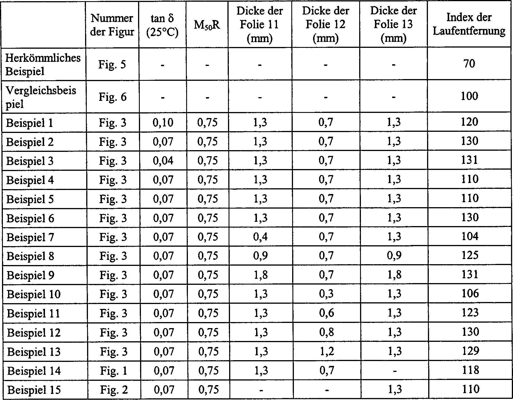
Als
nächstes
wird die Gummischutzfolie 11, 12, 13 bezüglich des
anpaßbaren
Gummieigenschaftbereichs und Dickenbereichs beschrieben. Diese Bereiche
werden erhalten durch Zusammenfassen der experimentellen Ergebnisse
für Radialreifen 1 mit
drei Reifengrößen für Personenwagen.
Diese Reifengrößen sind 225/60R16,
215/65R15 und 245/70R16 (für
Straßenfahrzeug).
Jeder dieser Reifen 1 wird auf einer empfohlenen Felge 15 für jede Reifengröße angebracht
und auf den maximalen Luftdruck aufgeblasen, damit sich der Reifen 1 an
die Felge 15 vollkommen anpaßt, und danach wird der Luftdruck
bis auf null verringert (ein Zustand, in dem der Ventilkern herausgenommen
ist). Eine solche Einheit aus dem Reifen 1 und der Felge 15 wird
unter einer Last, die ungefähr
76% der maximalen Lastkapazität
des Reifens entspricht, gegen eine Trommel geschoben, die mit einer
Oberflächengeschwindigkeit
von 89 km/h rotiert, wobei die Laufentfernung bis zum Auftreten
einer Störung
gemessen wird, um die Plattlaufhaltbarkeit zu beurteilen.Next is the rubber protection film 11 . 12 . 13 regarding the conformable rubber property range and thickness range. These ranges are obtained by summarizing the experimental results for radial tires 1 with three tire sizes for passenger cars. These tire sizes are 225 / 60R16, 215 / 65R15 and 245 / 70R16 (for road vehicle). Each of these tires 1 is on a recommended rim 15 fitted for each tire size and inflated to the maximum air pressure to allow the tire 1 to the rim 15 then completely adapts, and then the air pressure is reduced to zero (a state in which the valve core is taken out). Such a unit from the tire 1 and the rim 15 is pushed against a drum which rotates at a surface speed of 89 km / h under a load corresponding to approximately 76% of the maximum load capacity of the tire, and the running distance is measured until a disturbance occurs to evaluate the run flat durability.
Da
die Wärmeerzeugung
in dem Gebiet α bei
dem Lauf des Reifens 1 in dem Plattlaufzustand unter Belastung
groß ist,
ist es erforderlich, Probleme infolge einer hohen Temperatur zu
vermeiden, so daß der
tan δ bei
25°C zuerst
als die Gummieigenschaft, die die Wärmeerzeugung kontrolliert,
genommen wird.Since the heat generation in the area α at the run of the tire 1 In the run-flat state under load, it is necessary to avoid problems due to a high temperature, so that the tan δ at 25 ° C is first taken as the rubber property controlling the heat generation.
Ein
Experiment zur Beurteilung der Plattlaufhaltbarkeit bei vier Niveaus
von tan δ wird
bei den Gummischutzfolien 11, 12 und 13 ausgeführt, und
die experimentellen Ergebnisse werden in der 8 graphisch dargestellt.
Dann wird ein Experiment zur Beurteilung der Plattlaufhaltbarkeit
ausgeführt,
wozu der 50%-Elastizitätsmodul
(M50), der sich bei der Gummischutzfolie 11, 12, 13 wirksam
konzentrieren kann, in vier Niveaus als Verhältnis zu dem 50%-Elastizitätsmodul
(M50) der Gummiverstärkungsschicht 9 verwendet,
und die experimentellen Ergebnisse werden in der 9 graphisch
dargestellt. In diesem Fall wird sowohl bei dem Wulstfüllergummi 8,
als auch bei der Gummiverstärkungsschicht 9 der
gleiche Gummi verwendet.An experiment for assessing runflat durability at four levels of tan δ is found in rubber protective films 11 . 12 and 13 executed, and the experimental results are in the 8th graphic shown. Then, an experiment for evaluating run-flat durability is carried out, including the 50% modulus (M 50 ) exhibited by the rubber protective film 11 . 12 . 13 in four levels relative to the 50% modulus (M 50 ) of the rubber reinforcement layer 9 used, and the experimental results are in the 9 shown graphically. In this case, both the bead filler rubber will be used 8th , as well as the rubber reinforcing layer 9 the same rubber used.
Andererseits
wird die anpaßbare
Dicke der Gummischutzfolien 11, 12 und 13 in
den Fall der Gummischutzfolien 11, 13 und den
Fall der Gummischutzfolie 12 unterteilt, und die jeweilige
Dicke wird in fünf
Niveaus aufgeteilt. Ein Experiment zur Beurteilung der Plattlaufhaltbarkeit
des Reifens 1 wird bei jedem Niveau ausgeführt, und
die experimentellen Ergebnisse werden in dem Fall der Gummischutzfolien 11, 13 in
der 10, und in dem Fall der Gummischutzfolie 12 in
der 11 graphisch dargestellt. Der numerische Wert
auf der Ordinate in den 8-11 wird
durch einen Index wiedergegeben, auf der Basis eines Indexwertes 100 für den verbesserten
Reifen 21A des herkömmlichen
Reifens 20 als Kontrollreifen. Je größer der Indexwert ist, desto besser
ist die Eigenschaft. Außerdem
repräsentiert
das Zeichen "•" Lagenablösungsausfall,
und das Zeichen "∎" ist nicht Lagenablösungsausfall,
aber repräsentiert
Bruch der Gummiverstärkungsschicht 9.On the other hand, the adaptable thickness of the rubber protective films 11 . 12 and 13 in the case of rubber protective films 11 . 13 and the case of the rubber protective film 12 divided, and the respective thickness is divided into five levels. An experiment to assess the runflat durability of the tire 1 is carried out at each level, and the experimental results become in the case of rubber protective films 11 . 13 in the 10 , and in the case of the rubber protective film 12 in the 11 shown graphically. The numeric value on the ordinate in the 8th - 11 is represented by an index based on an index value 100 for the improved tire 21A of the conventional tire 20 as a control tire. The larger the index value, the better the property. In addition, the character "•" represents ply separation failure, and the character "∎" is not ply separation failure, but represents breakage of the rubber ply layer 9 ,
Aus
der 8 ist ersichtlich, daß Gummi, der einen tan δ bei 25°C von nicht
mehr als 0,11 hat, als Gummischutzfolie 11, 12, 13 geeignet
ist, während
dann, wenn der tan δ kleiner
als 0,04 ist, die Verbesserung der Plattlaufhaltbarkeit nicht erkannt
wird (aufgrund eines anderen Experiments), und die Zugfestigkeit
zu klein wird, und der Gummi als Gummi für die Gummischutzfolie ungeeignet
ist, so daß der
tan δ bei
25°C vorzugsweise
in dem Bereich von 0,04-0,11 liegt.From the 8th It can be seen that rubber having a tan δ at 25 ° C of not more than 0.11 as a rubber protective film 11 . 12 . 13 while the tan δ is smaller than 0.04, the improvement in run-flat durability is not recognized (due to another experiment), and the tensile strength becomes too small, and the rubber is unsuitable as a rubber for the rubber protective film, so that the tan δ at 25 ° C is preferably in the range of 0.04-0.11.
Aus
der 9 ist ersichtlich, daß das Verhältnis des 50%-Elastizitätsmoduls
der Gummischutzfolie zu dem 50%-Elastizitätsmodul des Wulstfüllergummis 8 und
der Gummiverstärkungsschicht 9 von
nicht mehr als 84% für
die Gummischutzfolie 11, 12, 13 geeignet
ist, während
dann, wenn das Verhältnis
des 50%-Elastizitätsmoduls
kleiner als 30% ist, ein extremer Stufenunterschied der Steifigkeit
zwischen dem Wulstfüllergummi 8 und
der Gummiverstärkungsschicht 9 auftritt,
und daher die Störung
nach den Gummischutzfolien 11, 12 und 13 übertragen
wird, um den Effekt bei Verwendung der Gummischutzfolien zu verschieben.
Daher ist der 50%-Elastizitätsmodul
der Gummischutzfolie 11, 12, 13 innerhalb
eines Bereichs von dem 0,30-0,84-fachen 50%-Elastizitätsmoduls
der Gummiverstärkungsschicht 9 (des
Wulstfüllergummis 8)
geeignet. Außerdem
basiert die obere Grenze in den 8 und 9 auf
nicht weniger als der 1,1-fachen Grenze des Kontrollreifens 21A.From the 9 It can be seen that the ratio of the 50% modulus of the rubber protective film to the 50% modulus of the bead filler rubber 8th and the rubber reinforcing layer 9 not more than 84% for the rubber protective film 11 . 12 . 13 while the ratio of the 50% modulus is less than 30%, there is an extreme step difference in stiffness between the bead filler rubber 8th and the rubber reinforcing layer 9 occurs, and therefore the disturbance after the rubber protective films 11 . 12 and 13 is transferred to move the effect when using the rubber protective films. Therefore, the 50% modulus of elasticity of the rubber protective film 11 . 12 . 13 within a range of 0.30-0.84 times the 50% modulus of the rubber reinforcing layer 9 (the bead filler rubber 8th ) suitable. In addition, the upper limit is based on the 8th and 9 on not less than 1.1 times the limit of the control tire 21A ,
Aus
der 10 ist ersichtlich, daß die Dicke der Gummischutzfolie 11, 13 vorzugsweise
nicht kleiner als 0,6 mm ist, und aus der 11 ist
ersichtlich, daß die
Dicke der Gummischutzfolie 12 vorzugsweise nicht kleiner
als 0,4 mm ist. Wenn andererseits die Dicke der Gummischutzfolie 11, 12, 13 4,0
mm übersteigt,
wird die Dicke zu groß,
und die Wärmeerzeugung
in den Bereichen, die mit den Gummischutzfolien 11, 12, 13 versehen
sind, wird übermäßig groß, wodurch
die Widerstandsfähigkeit
gegen Wärmeerzeugung
abnimmt, und daher kann die Verbesserung der Plattlaufhaltbarkeit
nicht erreicht werden. Daher liegt vorzugsweise die Dicke der Gummischutzfolie 11, 13 in
dem Bereich von 0,6-4,0 mm, und die Dicke der Gummischutzfolie 12 in
dem Bereich von 0,4-4,0 mm. Außerdem
basiert die untere Grenze in den 10 und 11 auf
nicht weniger als der 1,1-fachen Grenze des Kontrollreifens 21A.From the 10 It can be seen that the thickness of the rubber protection film 11 . 13 preferably not less than 0.6 mm, and from the 11 It can be seen that the thickness of the rubber protection film 12 preferably not less than 0.4 mm. On the other hand, if the thickness of the rubber protective film 11 . 12 . 13 Exceeds 4.0 mm, the thickness becomes too large, and the heat generation in the areas covered with the rubber protective films 11 . 12 . 13 are excessively large, whereby the resistance to heat generation decreases, and therefore, the improvement of the run-flat durability can not be achieved. Therefore, preferably, the thickness of the rubber protective film is 11 . 13 in the range of 0.6-4.0 mm, and the thickness of the rubber protective film 12 in the range of 0.4-4.0 mm. Moreover, the lower limit is based on the 10 and 11 on not less than 1.1 times the limit of the control tire 21A ,
Die
folgenden Beispiele werden zur Veranschaulichung der Erfindung wiedergegeben
und stellen keine Begrenzung der Erfindung dar.The
The following examples are given to illustrate the invention
and do not constitute a limitation of the invention.
Es
werden Radialreifen mit der Reifengröße 225/60R16 für Personenwagen
hergestellt, die die in den 1–3 wiedergegebene
Struktur haben, wobei die Karkasse 6 aus einer Umstülplage 6-1 und
einer herabfallenden Lage 6-2 besteht, jede dieser Lagen
gummigetränkte
Polyester-Cordfäden
mit radialer Anordnung enthält,
und der Gürtel 7 zwei
gummigetränkte,
schräge
Stahlcordschichten 7-1 und 7-2 und eine Decklage 7-3 aufweist,
wobei die Decklage 7-3 durch spiralförmiges Wickeln eines gummigetränkten Nylon-6,6-Cordfadens
gebildet ist.Radial tires with the size 225 / 60R16 for passenger cars are manufactured, which are in the 1 - 3 have reproduced structure, wherein the carcass 6 from a Umstülplage 6-1 and a falling position 6-2 Each of these layers contains rubber-impregnated polyester cords with a radial arrangement, and the belt 7 two rubber-saturated, slanted steel cord layers 7-1 and 7-2 and a top layer 7-3 has, wherein the top layer 7-3 by spirally winding a rubber-impregnated nylon 6,6 cord.
In
der Tabelle 1 sind der tan δ bei
25°C der
Gummischutzfolien 11, 12 und 13, das
Verhältnis
(M50R) des 50%-Elastizitätsmoduls der Gummischutzfolie 11, 12, 13 zu
dem 50%-Elastiztätsmodul
der Gummiverstärkungsschicht 9 (der
gleiche Gummi wie bei dem Wulstfüllergummi 8),
die Dicke d11 (mm) der Gummischutzfolie 11,
die Dicke d12 (mm) der Gummischutzfolie 12,
und die Dicke d13 (mm) der Gummischutzfolie 13 der
Beispiele 1-15 wiedergegeben. Außerdem ist die Figurnummer,
die dem jeweiligen Beispiel entspricht, in der Tabelle 1 wiedergegeben.
Um die Plattlaufhaltbarkeit jedes Beispiels zu beurteilen, wird
der herkömmliche
Reifen 20 verwirklicht, der die gleiche Struktur wie bei
dem Beispiel 1 hat, außer
daß die
Gummischutzfolie und der Kissengummi weggelassen sind, und der Vergleichsreifen 21A verwirklicht,
der die gleiche Struktur wie bei dem Beispiel 1 hat, außer daß die Gummischutzfolie
weggelassen ist.In Table 1, the tan δ at 25 ° C of the rubber protective films 11 . 12 and 13 , the ratio (M 50 R) of the 50% modulus of the rubber protective film 11 . 12 . 13 to the 50% modulus of the rubber reinforcement layer 9 (The same rubber as the bead filler rubber 8th ), the thickness d 11 (mm) of the rubber protective film 11 , the thickness d 12 (mm) of the rubber protective film 12 , and the thickness d 13 (mm) of the rubber protective film 13 the examples 1-15 played. In addition, the figure number corresponding to each example is shown in Table 1. To judge the runflat durability of each example, the conventional tire becomes 20 realized having the same structure as in Example 1, except that the rubber protective film and the Kis rubber, and the comparative tire 21A realized having the same structure as in Example 1, except that the rubber protective film is omitted.
Jeder
der Reifen der Beispiele 1–15,
des herkömmlichen
Beispiels und des Vergleichsbeispiels wird auf einer empfohlenen
Felge des Typs 61/2JJ angebracht und auf den maximalen oder nahezu
maximalen Luftdruck aufgeblasen, und dann durch Verringerung des
Luftdrucks auf null (Atmosphärendruck)
in den Plattlaufzustand gebracht. Danach wird der so erhaltene platte
Reifen unter einer Last von 570 kp, die ungefähr 76% der maximalen Lastkapazität von 750
kp entspricht, gegen eine Trommel geschoben, die mit einer Oberflächengeschwindigkeit
von 89 km/h rotiert, um die Laufentfernung bis zum Auftreten der
Reifenstörung
zu messen. Die gemessenen Ergebnisse werden durch einen Index wiedergegeben,
auf der Basis eines Indexwertes 100 als Plattlaufhaltbarkeit
für den
Vergleichsreifen. Je größer der
Indexwert ist, desto besser ist die Eigenschaft. Diese Ergebnisse
sind auch in der Tabelle 1 wiedergegeben. TABELLE
1 Each of the tires of Examples 1-15, Conventional Example and Comparative Example is mounted on a recommended type 61 / 2JJ rim and inflated to the maximum or near maximum air pressure, and then reduced to zero (atmospheric pressure) in the run-flat state by the air pressure brought. Thereafter, the thus-obtained flat tire is pushed against a drum rotating at a surface speed of 89 km / h under a load of 570 kp, which corresponds to approximately 76% of the maximum load capacity of 750 kp, to a running distance until occurrence of the tire disturbance to eat. The measured results are represented by an index based on an index value 100 as run-flat durability for the comparative tire. The larger the index value, the better the property. These results are also shown in Table 1. TABLE 1
Wie
aus den Ergebnissen der Tabelle 1 ersichtlich ist, ist bei allen
Reifen der Beispiele 1–15,
die die Gummischutzfolie 11, 12, 13 haben,
die Plattlaufhaltbarkeit verbessert, verglichen mit nicht nur dem
herkömmlichen
Reifen, sondern auch dem Vergleichsreifen, und die Plattlaufhaltbarkeit
kann wesentlich verbessert werden, wenn das 50%-Elastizitätsmodul-Verhältnis zu
der Gummverstärkungsschicht 9 in
geeigneter Weise festgelegt wird, oder die Dicke der Gummischutzfolie
in geeigneter Weise festgelegt wird.As can be seen from the results of Table 1, in all the tires of Examples 1-15, the rubber protective film is 11 . 12 . 13 which improves run flat durability as compared with not only the conventional tire but also the comparative tire, and the run flat durability can be substantially improved when the 50% modulus to the rubber reinforcing layer 9 is set appropriately, or the thickness of the rubber protective film is set appropriately.
Gemäß der Erfindung
werden Luftreifen verwirklicht, die insbesondere ein Querschnittverhältnis von nicht
weniger als 60 haben, und die zu vernünftigen Kosten hergestellt
werden können
infolge einer einfachen Struktur, bei der die herkömmliche
dicke Gummiverstärkungsschicht
zusammen mit nur einer Gummischutzfolie verwendet wird, die leichte
Handhabung für
die Felgenmontage oder dergleichen aufrechterhalten wird, und die
sichere Fahrt eines Fahrzeugs, wie eines Personenwagens oder dergleichen
sichergestellt wird, selbst wenn die Luft infolge eines Lochs oder
dergleichen rasch entweicht, und die funktioniert, selbst wenn die
Fahrt mit hoher Geschwindigkeit auf einer Schnellstraße bei oder
nahe bei einer Grenzgeschwindigkeit während einer langen Zeit fortgesetzt
wird, und die eine ausgezeichnete Plattlaufhaltbarkeit entwickeln
kann.According to the invention
Are pneumatic tires realized, in particular, a cross-sectional ratio of not
have less than 60, and that produced at reasonable cost
can be
due to a simple structure in which the conventional
thick rubber reinforcing layer
Used together with just a rubber protective film, the lightweight
Handling for
the rim assembly or the like is maintained, and the
safe driving of a vehicle, such as a passenger car or the like
is ensured even if the air due to a hole or
The like escapes quickly, and that works, even if the
Drive at high speed on a highway at or
continued near a limit speed for a long time
and that will develop an excellent run-flat durability
can.