DE69829079T2 - TURBINE BLADES MADE FROM SEVERAL CASTED SEGMENTS OF MONOCRYSTALLINE SUPER ALLOYS - Google Patents
TURBINE BLADES MADE FROM SEVERAL CASTED SEGMENTS OF MONOCRYSTALLINE SUPER ALLOYS Download PDFInfo
- Publication number
- DE69829079T2 DE69829079T2 DE69829079T DE69829079T DE69829079T2 DE 69829079 T2 DE69829079 T2 DE 69829079T2 DE 69829079 T DE69829079 T DE 69829079T DE 69829079 T DE69829079 T DE 69829079T DE 69829079 T2 DE69829079 T2 DE 69829079T2
- Authority
- DE
- Germany
- Prior art keywords
- weight
- monocrystalline
- segments
- superalloy
- bonding
- Prior art date
- Legal status (The legal status is an assumption and is not a legal conclusion. Google has not performed a legal analysis and makes no representation as to the accuracy of the status listed.)
- Expired - Lifetime
Links
Classifications
-
- F—MECHANICAL ENGINEERING; LIGHTING; HEATING; WEAPONS; BLASTING
- F01—MACHINES OR ENGINES IN GENERAL; ENGINE PLANTS IN GENERAL; STEAM ENGINES
- F01D—NON-POSITIVE DISPLACEMENT MACHINES OR ENGINES, e.g. STEAM TURBINES
- F01D5/00—Blades; Blade-carrying members; Heating, heat-insulating, cooling or antivibration means on the blades or the members
- F01D5/12—Blades
- F01D5/28—Selecting particular materials; Particular measures relating thereto; Measures against erosion or corrosion
-
- B—PERFORMING OPERATIONS; TRANSPORTING
- B23—MACHINE TOOLS; METAL-WORKING NOT OTHERWISE PROVIDED FOR
- B23H—WORKING OF METAL BY THE ACTION OF A HIGH CONCENTRATION OF ELECTRIC CURRENT ON A WORKPIECE USING AN ELECTRODE WHICH TAKES THE PLACE OF A TOOL; SUCH WORKING COMBINED WITH OTHER FORMS OF WORKING OF METAL
- B23H9/00—Machining specially adapted for treating particular metal objects or for obtaining special effects or results on metal objects
- B23H9/10—Working turbine blades or nozzles
-
- B—PERFORMING OPERATIONS; TRANSPORTING
- B23—MACHINE TOOLS; METAL-WORKING NOT OTHERWISE PROVIDED FOR
- B23K—SOLDERING OR UNSOLDERING; WELDING; CLADDING OR PLATING BY SOLDERING OR WELDING; CUTTING BY APPLYING HEAT LOCALLY, e.g. FLAME CUTTING; WORKING BY LASER BEAM
- B23K20/00—Non-electric welding by applying impact or other pressure, with or without the application of heat, e.g. cladding or plating
- B23K20/02—Non-electric welding by applying impact or other pressure, with or without the application of heat, e.g. cladding or plating by means of a press ; Diffusion bonding
- B23K20/023—Thermo-compression bonding
-
- B—PERFORMING OPERATIONS; TRANSPORTING
- B23—MACHINE TOOLS; METAL-WORKING NOT OTHERWISE PROVIDED FOR
- B23K—SOLDERING OR UNSOLDERING; WELDING; CLADDING OR PLATING BY SOLDERING OR WELDING; CUTTING BY APPLYING HEAT LOCALLY, e.g. FLAME CUTTING; WORKING BY LASER BEAM
- B23K20/00—Non-electric welding by applying impact or other pressure, with or without the application of heat, e.g. cladding or plating
- B23K20/16—Non-electric welding by applying impact or other pressure, with or without the application of heat, e.g. cladding or plating with interposition of special material to facilitate connection of the parts, e.g. material for absorbing or producing gas
-
- B—PERFORMING OPERATIONS; TRANSPORTING
- B23—MACHINE TOOLS; METAL-WORKING NOT OTHERWISE PROVIDED FOR
- B23K—SOLDERING OR UNSOLDERING; WELDING; CLADDING OR PLATING BY SOLDERING OR WELDING; CUTTING BY APPLYING HEAT LOCALLY, e.g. FLAME CUTTING; WORKING BY LASER BEAM
- B23K35/00—Rods, electrodes, materials, or media, for use in soldering, welding, or cutting
- B23K35/22—Rods, electrodes, materials, or media, for use in soldering, welding, or cutting characterised by the composition or nature of the material
- B23K35/24—Selection of soldering or welding materials proper
- B23K35/30—Selection of soldering or welding materials proper with the principal constituent melting at less than 1550 degrees C
- B23K35/3033—Ni as the principal constituent
-
- B—PERFORMING OPERATIONS; TRANSPORTING
- B23—MACHINE TOOLS; METAL-WORKING NOT OTHERWISE PROVIDED FOR
- B23P—METAL-WORKING NOT OTHERWISE PROVIDED FOR; COMBINED OPERATIONS; UNIVERSAL MACHINE TOOLS
- B23P15/00—Making specific metal objects by operations not covered by a single other subclass or a group in this subclass
- B23P15/04—Making specific metal objects by operations not covered by a single other subclass or a group in this subclass turbine or like blades from several pieces
-
- C—CHEMISTRY; METALLURGY
- C22—METALLURGY; FERROUS OR NON-FERROUS ALLOYS; TREATMENT OF ALLOYS OR NON-FERROUS METALS
- C22C—ALLOYS
- C22C19/00—Alloys based on nickel or cobalt
- C22C19/03—Alloys based on nickel or cobalt based on nickel
- C22C19/05—Alloys based on nickel or cobalt based on nickel with chromium
- C22C19/051—Alloys based on nickel or cobalt based on nickel with chromium and Mo or W
- C22C19/057—Alloys based on nickel or cobalt based on nickel with chromium and Mo or W with the maximum Cr content being less 10%
-
- C—CHEMISTRY; METALLURGY
- C22—METALLURGY; FERROUS OR NON-FERROUS ALLOYS; TREATMENT OF ALLOYS OR NON-FERROUS METALS
- C22F—CHANGING THE PHYSICAL STRUCTURE OF NON-FERROUS METALS AND NON-FERROUS ALLOYS
- C22F1/00—Changing the physical structure of non-ferrous metals or alloys by heat treatment or by hot or cold working
- C22F1/10—Changing the physical structure of non-ferrous metals or alloys by heat treatment or by hot or cold working of nickel or cobalt or alloys based thereon
-
- C—CHEMISTRY; METALLURGY
- C30—CRYSTAL GROWTH
- C30B—SINGLE-CRYSTAL GROWTH; UNIDIRECTIONAL SOLIDIFICATION OF EUTECTIC MATERIAL OR UNIDIRECTIONAL DEMIXING OF EUTECTOID MATERIAL; REFINING BY ZONE-MELTING OF MATERIAL; PRODUCTION OF A HOMOGENEOUS POLYCRYSTALLINE MATERIAL WITH DEFINED STRUCTURE; SINGLE CRYSTALS OR HOMOGENEOUS POLYCRYSTALLINE MATERIAL WITH DEFINED STRUCTURE; AFTER-TREATMENT OF SINGLE CRYSTALS OR A HOMOGENEOUS POLYCRYSTALLINE MATERIAL WITH DEFINED STRUCTURE; APPARATUS THEREFOR
- C30B11/00—Single-crystal growth by normal freezing or freezing under temperature gradient, e.g. Bridgman-Stockbarger method
-
- C—CHEMISTRY; METALLURGY
- C30—CRYSTAL GROWTH
- C30B—SINGLE-CRYSTAL GROWTH; UNIDIRECTIONAL SOLIDIFICATION OF EUTECTIC MATERIAL OR UNIDIRECTIONAL DEMIXING OF EUTECTOID MATERIAL; REFINING BY ZONE-MELTING OF MATERIAL; PRODUCTION OF A HOMOGENEOUS POLYCRYSTALLINE MATERIAL WITH DEFINED STRUCTURE; SINGLE CRYSTALS OR HOMOGENEOUS POLYCRYSTALLINE MATERIAL WITH DEFINED STRUCTURE; AFTER-TREATMENT OF SINGLE CRYSTALS OR A HOMOGENEOUS POLYCRYSTALLINE MATERIAL WITH DEFINED STRUCTURE; APPARATUS THEREFOR
- C30B29/00—Single crystals or homogeneous polycrystalline material with defined structure characterised by the material or by their shape
- C30B29/10—Inorganic compounds or compositions
- C30B29/52—Alloys
-
- F—MECHANICAL ENGINEERING; LIGHTING; HEATING; WEAPONS; BLASTING
- F01—MACHINES OR ENGINES IN GENERAL; ENGINE PLANTS IN GENERAL; STEAM ENGINES
- F01D—NON-POSITIVE DISPLACEMENT MACHINES OR ENGINES, e.g. STEAM TURBINES
- F01D5/00—Blades; Blade-carrying members; Heating, heat-insulating, cooling or antivibration means on the blades or the members
- F01D5/12—Blades
- F01D5/14—Form or construction
- F01D5/147—Construction, i.e. structural features, e.g. of weight-saving hollow blades
-
- F—MECHANICAL ENGINEERING; LIGHTING; HEATING; WEAPONS; BLASTING
- F01—MACHINES OR ENGINES IN GENERAL; ENGINE PLANTS IN GENERAL; STEAM ENGINES
- F01D—NON-POSITIVE DISPLACEMENT MACHINES OR ENGINES, e.g. STEAM TURBINES
- F01D5/00—Blades; Blade-carrying members; Heating, heat-insulating, cooling or antivibration means on the blades or the members
- F01D5/12—Blades
- F01D5/14—Form or construction
- F01D5/18—Hollow blades, i.e. blades with cooling or heating channels or cavities; Heating, heat-insulating or cooling means on blades
- F01D5/182—Transpiration cooling
- F01D5/184—Blade walls being made of perforated sheet laminae
-
- B—PERFORMING OPERATIONS; TRANSPORTING
- B23—MACHINE TOOLS; METAL-WORKING NOT OTHERWISE PROVIDED FOR
- B23K—SOLDERING OR UNSOLDERING; WELDING; CLADDING OR PLATING BY SOLDERING OR WELDING; CUTTING BY APPLYING HEAT LOCALLY, e.g. FLAME CUTTING; WORKING BY LASER BEAM
- B23K2101/00—Articles made by soldering, welding or cutting
- B23K2101/001—Turbines
-
- B—PERFORMING OPERATIONS; TRANSPORTING
- B23—MACHINE TOOLS; METAL-WORKING NOT OTHERWISE PROVIDED FOR
- B23K—SOLDERING OR UNSOLDERING; WELDING; CLADDING OR PLATING BY SOLDERING OR WELDING; CUTTING BY APPLYING HEAT LOCALLY, e.g. FLAME CUTTING; WORKING BY LASER BEAM
- B23K35/00—Rods, electrodes, materials, or media, for use in soldering, welding, or cutting
- B23K35/22—Rods, electrodes, materials, or media, for use in soldering, welding, or cutting characterised by the composition or nature of the material
- B23K35/24—Selection of soldering or welding materials proper
- B23K35/30—Selection of soldering or welding materials proper with the principal constituent melting at less than 1550 degrees C
- B23K35/3033—Ni as the principal constituent
- B23K35/304—Ni as the principal constituent with Cr as the next major constituent
-
- F—MECHANICAL ENGINEERING; LIGHTING; HEATING; WEAPONS; BLASTING
- F05—INDEXING SCHEMES RELATING TO ENGINES OR PUMPS IN VARIOUS SUBCLASSES OF CLASSES F01-F04
- F05D—INDEXING SCHEME FOR ASPECTS RELATING TO NON-POSITIVE-DISPLACEMENT MACHINES OR ENGINES, GAS-TURBINES OR JET-PROPULSION PLANTS
- F05D2230/00—Manufacture
- F05D2230/20—Manufacture essentially without removing material
- F05D2230/23—Manufacture essentially without removing material by permanently joining parts together
-
- F—MECHANICAL ENGINEERING; LIGHTING; HEATING; WEAPONS; BLASTING
- F05—INDEXING SCHEMES RELATING TO ENGINES OR PUMPS IN VARIOUS SUBCLASSES OF CLASSES F01-F04
- F05D—INDEXING SCHEME FOR ASPECTS RELATING TO NON-POSITIVE-DISPLACEMENT MACHINES OR ENGINES, GAS-TURBINES OR JET-PROPULSION PLANTS
- F05D2230/00—Manufacture
- F05D2230/40—Heat treatment
-
- F—MECHANICAL ENGINEERING; LIGHTING; HEATING; WEAPONS; BLASTING
- F05—INDEXING SCHEMES RELATING TO ENGINES OR PUMPS IN VARIOUS SUBCLASSES OF CLASSES F01-F04
- F05D—INDEXING SCHEME FOR ASPECTS RELATING TO NON-POSITIVE-DISPLACEMENT MACHINES OR ENGINES, GAS-TURBINES OR JET-PROPULSION PLANTS
- F05D2300/00—Materials; Properties thereof
- F05D2300/60—Properties or characteristics given to material by treatment or manufacturing
- F05D2300/607—Monocrystallinity
-
- Y—GENERAL TAGGING OF NEW TECHNOLOGICAL DEVELOPMENTS; GENERAL TAGGING OF CROSS-SECTIONAL TECHNOLOGIES SPANNING OVER SEVERAL SECTIONS OF THE IPC; TECHNICAL SUBJECTS COVERED BY FORMER USPC CROSS-REFERENCE ART COLLECTIONS [XRACs] AND DIGESTS
- Y02—TECHNOLOGIES OR APPLICATIONS FOR MITIGATION OR ADAPTATION AGAINST CLIMATE CHANGE
- Y02T—CLIMATE CHANGE MITIGATION TECHNOLOGIES RELATED TO TRANSPORTATION
- Y02T50/00—Aeronautics or air transport
- Y02T50/60—Efficient propulsion technologies, e.g. for aircraft
-
- Y—GENERAL TAGGING OF NEW TECHNOLOGICAL DEVELOPMENTS; GENERAL TAGGING OF CROSS-SECTIONAL TECHNOLOGIES SPANNING OVER SEVERAL SECTIONS OF THE IPC; TECHNICAL SUBJECTS COVERED BY FORMER USPC CROSS-REFERENCE ART COLLECTIONS [XRACs] AND DIGESTS
- Y10—TECHNICAL SUBJECTS COVERED BY FORMER USPC
- Y10T—TECHNICAL SUBJECTS COVERED BY FORMER US CLASSIFICATION
- Y10T428/00—Stock material or miscellaneous articles
- Y10T428/12—All metal or with adjacent metals
- Y10T428/12229—Intermediate article [e.g., blank, etc.]
- Y10T428/12271—Intermediate article [e.g., blank, etc.] having discrete fastener, marginal fastening, taper, or end structure
-
- Y—GENERAL TAGGING OF NEW TECHNOLOGICAL DEVELOPMENTS; GENERAL TAGGING OF CROSS-SECTIONAL TECHNOLOGIES SPANNING OVER SEVERAL SECTIONS OF THE IPC; TECHNICAL SUBJECTS COVERED BY FORMER USPC CROSS-REFERENCE ART COLLECTIONS [XRACs] AND DIGESTS
- Y10—TECHNICAL SUBJECTS COVERED BY FORMER USPC
- Y10T—TECHNICAL SUBJECTS COVERED BY FORMER US CLASSIFICATION
- Y10T428/00—Stock material or miscellaneous articles
- Y10T428/12—All metal or with adjacent metals
- Y10T428/12347—Plural layers discontinuously bonded [e.g., spot-weld, mechanical fastener, etc.]
-
- Y—GENERAL TAGGING OF NEW TECHNOLOGICAL DEVELOPMENTS; GENERAL TAGGING OF CROSS-SECTIONAL TECHNOLOGIES SPANNING OVER SEVERAL SECTIONS OF THE IPC; TECHNICAL SUBJECTS COVERED BY FORMER USPC CROSS-REFERENCE ART COLLECTIONS [XRACs] AND DIGESTS
- Y10—TECHNICAL SUBJECTS COVERED BY FORMER USPC
- Y10T—TECHNICAL SUBJECTS COVERED BY FORMER US CLASSIFICATION
- Y10T428/00—Stock material or miscellaneous articles
- Y10T428/12—All metal or with adjacent metals
- Y10T428/12431—Foil or filament smaller than 6 mils
-
- Y—GENERAL TAGGING OF NEW TECHNOLOGICAL DEVELOPMENTS; GENERAL TAGGING OF CROSS-SECTIONAL TECHNOLOGIES SPANNING OVER SEVERAL SECTIONS OF THE IPC; TECHNICAL SUBJECTS COVERED BY FORMER USPC CROSS-REFERENCE ART COLLECTIONS [XRACs] AND DIGESTS
- Y10—TECHNICAL SUBJECTS COVERED BY FORMER USPC
- Y10T—TECHNICAL SUBJECTS COVERED BY FORMER US CLASSIFICATION
- Y10T428/00—Stock material or miscellaneous articles
- Y10T428/12—All metal or with adjacent metals
- Y10T428/12493—Composite; i.e., plural, adjacent, spatially distinct metal components [e.g., layers, joint, etc.]
- Y10T428/12771—Transition metal-base component
- Y10T428/12861—Group VIII or IB metal-base component
- Y10T428/12944—Ni-base component
Landscapes
- Engineering & Computer Science (AREA)
- Mechanical Engineering (AREA)
- Chemical & Material Sciences (AREA)
- Materials Engineering (AREA)
- General Engineering & Computer Science (AREA)
- Organic Chemistry (AREA)
- Metallurgy (AREA)
- Crystallography & Structural Chemistry (AREA)
- Physics & Mathematics (AREA)
- Thermal Sciences (AREA)
- Architecture (AREA)
- Inorganic Chemistry (AREA)
- Turbine Rotor Nozzle Sealing (AREA)
- Pressure Welding/Diffusion-Bonding (AREA)
- Crystals, And After-Treatments Of Crystals (AREA)
Description
TECHNISCHES GEBIET DER ERFINDUNGTECHNICAL FIELD OF THE INVENTION
Die vorliegende Erfindung bezieht sich auf Gasturbinenmaschinen für die Stromerzeugung und insbesondere auf Schaufeln für derartige Turbinen, die aus mehreren Segmenten aus gegossenen Superlegierungen bestehen.The The present invention relates to gas turbine engines for power generation and in particular on blades for Such turbines, which consist of several segments of cast superalloys consist.
BISHERIGER STAND DER TECHNIKPREVIOUS STATE OF THE ART
Dem Stand der Technik entsprechende Lauf- und Leitschaufeln, die in modernen, hocheffizienten Gasturbinenmaschinen für die Stromerzeugung Anwendung finden, stützen sich auf hochqualitative Materialien wie etwa monokristalline Legierungen und Präzisionssteuerung der Innen- und Außenabmessungen des Bauteils. Auf Grund der großen Abmessungen dieser Bauteile wird auf verschiedenen Wegen eine kosteneffiziente Fertigung angestrebt.the State of the art corresponding runners and guide vanes, the modern, high-efficiency gas turbine engines for power generation application find, support on high-quality materials such as monocrystalline alloys and precision control the inside and outside dimensions of the component. Because of the big one Dimensions of these components is cost-effective in various ways sought.
Landgestützte Gasturbinen, z. B. das ATS-System (Advanced Turbine System), das sich derzeit in der Entwicklung befindet, erfordern kostengünstige Hochleistungskomponenten, die aus Hightech-Materialien vorgefertigt werden. Die erste und zweite Reihe der Laufschaufeln und Leitschaufeln einer Turbine beinhalten komplexe Innen- und Außengeometrien und sollten aus fehlerfreien Materialien vorgefertigt werden. Obwohl Komponenten mit derartigen Eigenschaften für Flugzeugturbinen entwickelt wurden, bilden die größeren Abmessungen von Komponenten in Turbinen, die zur Stromerzeugung eingesetzt werden, eine erhebliche Herausforderung. Bisher erwies es sich bei Gussversuchen als unmöglich, fehlerfreie große Komponenten in signifikanten Stückzahlen herzustellen.Land-based gas turbines, z. For example, the ATS system (Advanced Turbine System), which is currently being in development, require low-cost, high-performance components, made of high-tech materials prefabricated. The first and second row of blades and vanes of a turbine include complex internal and external geometries and should be prefabricated from faultless materials. Although components with such properties for Aircraft turbines were developed, form the larger dimensions of components in turbines used to generate electricity, a significant challenge. So far, it proved in casting trials as impossible flawless big Components in significant quantities manufacture.
Ein alternativer Fertigungsansatz würde darin bestehen, fehlerfreie kleinere Unterkomponenten zu gießen und diese anschließend unter Einsatz eines hochqualitativen Bonding-Prozesses zusammenzufügen. Derzeit ist jedoch die erforderliche Verbindungstechnik für fortschrittliche monokristalline Legierungen wie CMSX-4, die für den Einsatz in Turbinen der ATS-Klasse bestimmt sind, nicht verfügbar.One alternative manufacturing approach would to cast error-free smaller subcomponents and this afterwards using a high quality bonding process. Currently however, is the required joining technique for advanced monocrystalline alloys such as CMSX-4, which are suitable for use in turbines of the ATS class are determined, not available.
Das US-Patent 5.061.154 offenbart eine Turbine, die aus mehreren zusammengefügten Schaufeln besteht.The U.S. Patent 5,061,154 discloses a turbine comprising a plurality of assembled blades consists.
ZUSAMMENFASSENDE BESCHREIBUNG DER ERFINDUNGSUMMARY DESCRIPTION THE INVENTION
Gasturbinenschaufeln in Heißabschnitten werden aus Gussstücken vorgefertigt, die aus monokristallinen Superlegierungen bestehen, indem qualitativ hochwertige Schalenabschnitte oder Teile gefügt werden. Das vorliegende Verfahren ermöglicht die Fertigung großer, qualitativ hochwertiger Turbinenschaufeln durch das Verbinden kleiner, qualitativ hochwertiger Abschnitte; dies ist im Vergleich zu früheren Versuchen, Turbinenschaufeln als Einzelstücke zu gießen, zu sehen, die eine sehr geringe Ausbeute ergeben und damit einhergehend hohe Teilestückkosten bedingen.Gas turbine blades in hot sections are made of castings prefabricated, which consist of monocrystalline superalloys, by adding high quality shell sections or parts. The present method allows the manufacturing big, high-quality turbine blades by connecting small, high quality sections; this is compared to previous attempts Turbine blades as individual pieces to pour, to see, which results in a very low yield and with it high parts costs require.
Das vorliegende Verfahren ermöglicht die hochproduktive Fertigung großformatiger, monokristalliner Bauteile für Gasturbinen. Das vorliegende Verfahren bringt die Kosten für Turbinenschaufeln in eine Größenordnung, die für gewerbliche Anwendungen erschwinglich ist. Das Verfahren ermöglicht es, dass gleichzeitig präzise Teileprofile sowie optimale Materialqualität und -leistung monokristalliner Werkstoffe erreicht werden, was durch herkömmliches Gießen monokristalliner Werkstoffe nicht möglich ist. Dadurch, dass dieses Verfahren den Gusskern überflüssig macht, ermöglicht es die Steuerung der Geometrie sowie der Merkmale von Innenkomponenten. Indem außerdem ein Zugang zu den inneren Kühlkanälen während der Fertigung geschaffen wird, ergibt sich die Möglichkeit einer präzisen Qualitätskontrolle der Kühlmerkmale in den Schaufeln sowie ihrer Wandmaße. Zudem kann das Vorhandensein von inneren Kornstrukturen und von Mängeln ermittelt werden. Die Erfindung ermöglicht präziser gesteuerte monokristalline Turbinenschaufeln zu deutlich reduzierten Kosten.The present method allows the highly productive production of large-format, monocrystalline components for gas turbines. The present method brings the cost of turbine blades into one Magnitude, the for commercial applications is affordable. The procedure makes it possible that at the same time precise Part profiles as well as optimum material quality and performance monocrystalline Materials are achieved, which by conventional casting monocrystalline Materials not possible is. Because this process makes the casting core redundant, allows it controls the geometry as well as the characteristics of interior components. In addition an access to the inner cooling channels during the Production is created, there is the possibility of a precise quality control the cooling characteristics in the shovels and their wall measurements. In addition, the presence of internal grain structures and defects. The Invention allows more precise controlled monocrystalline turbine blades at significantly reduced cost.
Die Schaufel wird so konstruiert, dass es möglich ist, die Fügelinien in wenig belasteten Bereichen zu positionieren. Die Teile der Schaufel können mit einem speziell vorgesehenen Übermaß gegossen werden, um ein optimaleres Zurichten für das Fügen zu ermöglichen. Umformverfahren können angewendet werden, um die Teile zu profilieren und zuzurichten. Die Turbinenschaufelteile können durch maschinelles Bearbeiten (z. B. Ko-EDM) für eine Präzisionszurichtung in der Größenordnung von 0,025 mm (0,001 Zoll) vorbereitet werden. Die Fügespalten zwischen den Teilen der Schaufel werden dann mit einer Folie oder Paste gefüllt. Bonding-Folien und Wärmebehandlungsverfahren werden so ausgewählt, dass sie qualitativ hochwertige und hochfeste Fügenähte ergeben. Gemäß einem Ausführungsbeispiel können monokristalline Abschnitte mit anderen monokristallinen Abschnitten verbunden werden. Gemäß einem anderen Ausführungsbeispiel können monokristalline Abschnitte mit polykristallinen Abschnitten, einschließlich gerichtet erstarrten Abschnitten, verbunden werden, um kostengünstig Hybridschaufeln herzustellen.The bucket is designed so that it is possible to position the joint lines in lightly loaded areas. The parts of the blade can be cast with a specially designed oversize to allow more optimal dressing for the joint. Forming processes can be applied to profiling and dressing the parts. The turbine blade parts may be prepared by machining (eg, Ko-EDM) for a precision finish on the order of 0.025 mm (0.001 inches). The joining gaps between the parts of the blade are then filled with a foil or paste. Bonding films and heat treatment processes are selected to give high quality and high strength jointing. According to one embodiment, monocrystalline sections may be connected to other monocrystalline sections. According to another embodiment, monocrystalline sections may be connected to polycrystalline sections, including directionally solidified sections, to inexpensively produce hybrid blades.
In der Entwurfsphase wird eine Turbinenschaufel längs belastungsarmer Bereiche in zwei oder mehr Teile geteilt. Gemäß einem Ausführungsbeispiel ermöglicht das Teilen längs einer einzigen Oberfläche, die in etwa längs der Skelettlinie der Schaufel verläuft, das effiziente Zusammenfügen hochqualitativer Gussstücke, um so im Wesentlichen fehlerfreie Schaufeln aus gegossenen monokristallinen Superlegierungen zu erhalten, die in herkömmlicher Weise mit hoher Ausbeute nicht fehlerfrei hergestellt werden können. Gemäß einem anderen Ausführungsbeispiel wird eine Schaufel in der Entwurfsphase in vier Teile geteilt, indem sie – zusätzlich zum ursprünglichen Abschnitt längs einer einzigen Oberfläche, die in etwa längs der Skelettlinie des Flügelprofils verläuft – längs zweier weiterer Oberflächen innerhalb des Schaufelfußabschnitts geteilt wird. Auf diese Weise werden vier Abschnitte durch erneutes Teilen der beiden ursprünglichen Abschnitte in zwei weitere Abschnitte definiert. Diese beiden zusätzlichen Abschnitte befinden sich vorzugsweise im Schaufelfuß. Sie werden auf belastungsarmen Oberflächen vorgesehen und so konturiert, dass sie zwischen der Oberflächenkontur der Außenfläche des Schaufelfußes und der inneren Fügeflächenkontur verlaufen. Wenn anschließend die verschiedenen Teile gegossen und zu einem einzigen Gefüge mittels TLP-Bonding (Transient Liquid Phase Bonding = Bonding mit transienter Flüssigphase) gefügt werden, können qualitativ hochwertige Gussstücke effizient gefügt werden, um so im Wesentlichen fehlerfreie Schaufeln zu erhalten, die bei sehr hohen Temperaturen arbeiten können.In The design phase will be a turbine blade along low-load areas divided into two or more parts. According to one embodiment allows splitting along a single surface, the approximately longitudinal the skeleton line of the bucket runs, the efficient joining of high quality Castings, um So essentially flawless blades made of cast monocrystalline To obtain superalloys in a conventional manner in high yield can not be made without error. According to another embodiment In the design phase, a bucket is divided into four parts by they - in addition to original Section along a single surface, the approximately longitudinal the skeleton line of the wing profile runs - along two other surfaces within the blade root section is shared. In this way, four sections are replaced by again Divide the two original ones Sections are defined in two more sections. These two extra Sections are preferably in the blade root. you will be on low-stress surfaces provided and contoured so that they are between the surface contour the outer surface of the blade root and the inner joining surface contour run. If subsequently the different parts are poured and made into a single structure by means of TLP bonding (transient liquid phase bonding = bonding with transient Liquid phase) together can, can high quality castings efficiently joined so as to obtain essentially faultless blades, which can work at very high temperatures.
Gemäß einem weiteren Ausführungsbeispiel wird der Flügelprofilabschnitt der Turbinenschaufel aus einer monokristallinen Legierung gegossen, während die Außenanteile des Schaufelfußes aus einer polykristallinen Legierung gegossen werden. Qualitativ hochwertige Einzelstücke werden mit hoher Ausbeute gegossen und anschließend durch ein Bonding-Verfahren wie beispielsweise TLP-Bonding gefügt, um im Wesentlichen fehlerfreie, qualitativ hochwertige Turbinenschaufeln mit kostengünstiger Fertigungsausbeute zu erhalten.According to one another embodiment becomes the wing profile section the turbine blade is cast from a monocrystalline alloy, while the outside parts of the blade foot be cast from a polycrystalline alloy. qualitatively high quality individual pieces are cast in high yield and then by a bonding process such as TLP bonding joined to essentially error-free, high quality turbine blades with cheaper To obtain production yield.
Durch Reduzieren der Querschnittsfläche der Gussstücke kann im Fertigteil eine höhere Qualität erreicht werden, d. h., die Produktion von Korngrenzen, Splittern und A-Seigerungen kann reduziert werden, wenn die Querschnittsfläche des Gussstücks verringert wird. Da der Gussstückquerschnitt zudem als Vollprofil gewählt werden kann, können Gussprobleme vermieden werden, die mit dem Gießen um relativ scharfe Kernmerkmale herum zusammenhängen. Indem diese Ansätze zur Minderung der Tendenz zur Produktion fehlerhafter Gussstücke gewählt werden, ist eine Gussausbeute in der Größenordnung von 80 bis 90 Prozent möglich.By Reduce the cross-sectional area the castings can be a higher in the finished part quality be reached, d. h., the production of grain boundaries, splinters and A segregations can be reduced if the cross-sectional area of the casting is reduced. Since the casting cross section also chosen as solid profile can, can Casting problems are avoided with casting around relatively sharp core features hang around. By doing these approaches to reduce the tendency to produce defective castings, is a casting yield of the order of magnitude from 80 to 90 percent possible.
Das vorliegende Verfahren, das auf der Montage von Unterkomponenten der Schaufelstruktur basiert, besteht darin, dass weniger anfällige Fügeflächen in Unterkomponenten integriert werden, die so ausgelegt sind, dass sie die allgemeinen thermischen, aerodynamischen und mechanischen Anforderungen erfüllen. Diese Segmentierung trennt die Komponente in kleinere Segmente, die leicht gießbar sind, die sich für problemloses Montieren eignen und die die Fügeebene(n) an gering belastete Stellen verlegen. Vorzugsweise versucht der Segmentierprozess in der Entwurfsphase, durchgehende, vorsichtig gekrümmte Flächen zu ermitteln, die keinen erheblichen Lasten quer zur Fügefläche ausgesetzt sind. Die Eliminierung scharfer Krümmungen und Unterkomponenten mit Oberflächen ohne hinein- oder herausragende Merkmale verbessert nicht nur die Gussausbeute; sondern erleichtert auch die Anwendung des Bonding-Mediums und das Einspannen der Komponenten während des Fügens.The present method, which is based on the assembly of subcomponents is based on the blade structure, is that less susceptible joining surfaces in Subcomponents are integrated, which are designed so that they are the general thermal, aerodynamic and mechanical Meet requirements. These Segmentation separates the component into smaller segments that are light pourable are, who are for are easy to mount and that the joining plane (s) is slightly loaded Relocate jobs. Preferably, the segmentation process tries in the design phase, to identify continuous, gently curved surfaces that do not exposed to considerable loads across the joint surface are. The elimination of sharp bends and subcomponents with surfaces without intrinsic or outstanding features not only improves the Cast yield; but also facilitates the application of the bonding medium and clamping the components during joining.
Der bevorzugte Bonding-Prozess, d. h. TLP-Bonding, bietet die Möglichkeit, große Schaufeln, die aus fortschrittlichen monokristallinen Legierungen bestehen, zusammenzufügen. Die chemische Zusammensetzung der Fügefolie kann so maßgeschneidert werden, dass selbst bei Monokristallen ein einheitliches Gefüge über den gesamten Fügebereich gewonnen werden kann; dies gilt mit der Maßgabe, dass die Wärmebehandlung nach dem Fügen so angepasst werden kann, dass ein optimales γ/γ'-Gefüge im Fügebereich sowie im Basismaterial erzielt wird. Neben dem Abgleich des Mikrogefüges in der Fügezone mit dem Mikrogefüge des Basismaterials wird die Bonding-Folie so ausgewählt, dass sie kompatibel mit dem Wärmebehandlungsprozess ist, der für das Basismaterial verwendet wird.Of the preferred bonding process, d. H. TLP bonding, offers the possibility size Shovels made from advanced monocrystalline alloys consist of joining together. The chemical composition of the joining film can be customized be that even with monocrystals a uniform structure over the entire joining area can be won; this is true with the proviso that the heat treatment after joining can be adjusted so that an optimal γ / γ'-structure in the joining area as well as in the base material. In addition to the adjustment of the microstructure in the joint zone with the microstructure of the base material, the bonding film is selected so that they are compatible with the heat treatment process is that for the base material is used.
Computer Aided Design (CAD) in Kombination mit einer dem Stand der Technik entsprechenden Finite-Elemente-Modellierung (FEM) erleichtert erheblich die Entwicklung und mechanische Analyse segmentierter Unterkomponenten. Diese Techniken erlauben die Definition der Schaufelgeometrie mit Segmentierungsflächen, die das Volumenmodell in unterschiedliche Bereiche unterteilen. Beginnend mit der Originalschaufel fährt der Segmentierungsprozess fort mit der Auswahl potenzieller Segmentierungsflächen und ihrer quantitativen Beurteilung vom Standpunkt der voraussichtlich auf die Flächen wirkenden Lasten. Die Flächen werden dann qualitativ vom Standpunkt der Bereitstellung glatter, durchgehender Flächen aus betrachtet, um das Gießen und Fügen zu erleichtern. Die ausgewählte(n) Fläche(n) kann bzw. können dann so modifiziert werden, dass Merkmale wie etwa scharfe Ecken eliminiert werden, die die Gussqualität beeinträchtigen und hinderlich für das Fügen sind. Die modifizierte Fläche kann dann erneut mit Hilfe des FEM-Verfahrens analysiert werden, um die quer zur Fügelinie wirkenden potenziellen Lasten zu bewerten.computer Aided Design (CAD) in combination with a state of the art corresponding finite element modeling (FEM) facilitates considerably the development and mechanical analysis of segmented subcomponents. These techniques allow the definition of blade geometry with Segmentation surfaces, which divide the volume model into different areas. Starting with the original bucket, the segmentation process continues continue with the selection of potential segmentation surfaces and their quantitative assessment from the standpoint of on the surfaces acting loads. The surfaces become qualitatively smoother from the standpoint of providing continuous surfaces considered from the casting and joining to facilitate. The selected (s) Surface (s) can or can then modified so that features such as sharp corners be eliminated, which affect the casting quality and are a hindrance to the joining. The modified area can then be analyzed again using the FEM method the cross to the joint line evaluate potential burdens.
Zu den heutigen Schaufelkonstruktionsanforderungen zählen Ermüdungsfestigkeit bei Schnell- und Langsamzyklus (HCF und LCF), Kriechfestigkeit, Plastizität und thermomechanische Ermüdungsfestigkeit (TMF). Die FEM-Analyse potenzieller Fügeflächen zeigt, ob die mechanischen Eigenschaften des gefügten Metalls diese Anforderungen erfüllen können. Konkret müssen die Fügezoneneigenschaften die durch die Anforderungen definierten Eigenschaften übertreffen. Obwohl der vorliegende Bonding-Prozess vorzugsweise einen Sollwert von 90 Prozent der Basismetallleistung erreicht, da die resultierenden Materialeigenschaften an der Fügung leicht reduziert sein können, wird die Fügefläche an einer Stelle positioniert, an der die Betriebsbelastungen minimiert sind.To Today's bucket design requirements include fatigue strength in fast cycle and slow cycle (HCF and LCF), creep resistance, plasticity and thermo-mechanical fatigue strength (TMF). The FEM analysis of potential joining surfaces shows, whether the mechanical properties of the joined metal meet these requirements fulfill can. In concrete terms the joining zone properties exceed the requirements defined by the requirements. Although the present bonding process preferably has a setpoint achieved by 90 percent of the base metal performance, as the resulting Material properties at the joint can be easily reduced, is the joint surface at one Position positioned where the operating loads are minimized.
Ein Aspekt der vorliegenden Erfindung ist die Bereitstellung eines Verfahrens zur Herstellung einer Turbinenschaufel, die eine monokristalline Legierung beinhaltet, für eine landgestützte Gasturbine. Das Verfahren umfasst folgende Schritte: Auswahl einer monokristallinen Superlegierung zur Ausbildung der Turbinenschaufel, Auswahl einer Mehrzahl von Segmenten der Turbinenschaufel, die aus einer Mehrzahl von einzelnen Superlegierungsgussstücken ausgebildet werden soll, wobei die Anordnung der Segmente so gewählt wird, dass die Fügenähte zwischen benachbarten Segmenten an gering belasteten Stellen positioniert werden, Herstellen der Segmente durch Gießen der Superlegierung in eine Mehrzahl von Gießformen und Fügen der Segmente. Die Erfindung ist dadurch gekennzeichnet, dass der Schaufelfußanteil aus einer polykristallinen Superlegierung besteht.One Aspect of the present invention is the provision of a method for producing a turbine blade, which is a monocrystalline Includes alloy, for a land based Gas turbine. The procedure comprises the following steps: Selection of a monocrystalline superalloy for forming the turbine blade, Selection of a plurality of segments of the turbine blade, consisting of formed of a plurality of individual superalloy castings is to be, the arrangement of the segments is chosen so that the joining seams between positioned adjacent segments at low loaded points Making the segments by casting the superalloy into one Plurality of molds and joining the segments. The invention is characterized in that the root portion consists of a polycrystalline superalloy.
Ein weiterer Aspekt der vorliegenden Erfindung besteht in der Bereitstellung einer Turbinenschaufel für landgestützte Gasturbinen, die eine Mehrzahl von Segmenten beinhaltet, die aus einer polykristallinen Superlegierung bestehen. Diese Segmente sind so ausgelegt, dass die Fügenähte zwischen den Segmenten an wenig belasteten Stellen positioniert sind. Die Turbinenschaufel ist dadurch gekennzeichnet, dass der Schaufelfußanteil aus einer polykristallinen Superlegierung besteht.One Another aspect of the present invention is the provision a turbine blade for land-based Gas turbines, which includes a plurality of segments made of consist of a polycrystalline superalloy. These segments are designed so that the joining seams between the segments are positioned at low loaded points. The Turbine blade is characterized in that the Schaufelfußanteil consists of a polycrystalline superalloy.
Dieser und andere Aspekte der vorliegenden Erfindung lassen sich anhand der nachstehenden Beschreibung besser verstehen.This and other aspects of the present invention can be understood better understand the description below.
KURZE BESCHREIBUNG DER ZEICHNUNGENBRIEF DESCRIPTION OF THE DRAWINGS
AUSFÜHRLICHE BESCHREIBUNGDETAILED DESCRIPTION
In Übereinstimmung mit der vorliegenden Erfindung reduziert eine durch hohe Ausbeute charakterisierte Produktion von Turbinenschaufeln aus monokristallinen Superlegierungen die Kosten monokristalliner Schaufeln für Turbinen. Derzeit wird die Produktionsausbeute bei Schaufeln, die aus einem einzigen Gussstück bestehen, für große landgestützte Turbinen auf weniger als 20 Prozent geschätzt, wobei die Hauptproblematik in der Dicke des Gussstücks liegt. Wird diese Dicke auf weniger als 2 bzw. 2,5 cm (ca. 0,75 oder 1 Zoll) reduziert, kann die Fehlerrate gesenkt und die Ausbeute erhöht werden. Die Gussausbeute bei Halbabschnitten von Schaufeln dürfte sich auf Grund ihrer reduzierten Dicke in einer Größenordnung von 90 Prozent bewegen. So kann die Produktionsausbeute der gefügten Schaufeln gemäß vorliegender Erfindung ca. 80 Prozent oder mehr betragen – verglichen mit der geschätzten Ausbeute von 20 Prozent bei ungeteilten Gussstücken.In accordance with the present invention reduces one by high yield Characterized production of turbine blades made of monocrystalline Superalloys the cost of monocrystalline blades for turbines. Currently, the production yield of blades, which consists of a single casting exist for size land-based Turbines estimated at less than 20 percent, with the main problem in the thickness of the casting lies. If this thickness is less than 2 or 2.5 cm (about 0.75 or 1 inch), the error rate can be lowered and the yield elevated become. The casting yield at half-sections of blades is likely move on the order of 90 percent due to their reduced thickness. Thus, the production yield of the joined blades according to the present Invention about 80 percent or more - compared with the estimated yield of 20 percent for undivided castings.
Der Begriff „Turbinenschaufel", wie er hier benutzt wird, meint eine Komponente landgestützter Gasturbinen, einschließlich der Laufschaufeln und stationären Leitschaufeln derartiger Turbinen. Laufschaufeln beinhalten typischerweise einen Flügelprofilanteil und einen Schaufelfußanteil, einschließlich eines Schaufelblocks. Stationäre Leitschaufeln beinhalten typischerweise einen mittleren Flügelprofilanteil und zwei Bandanteile, die als Äquivalente der Fußanteile bei Laufschaufeln angesehen werden können. Die Turbinenschaufeln sind relativ groß und haben vorzugsweise eine Gesamtlänge von mindestens ca. 305 mm (12 Zoll), eine Flügeltiefe von mindestens ca. 102 mm (4 Zoll) und eine Flügeldicke von mindestens ca. 8 mm (5/16 Zoll). Bei Laufschaufeln beträgt die Mindestlänge des Flügelprofilanteils der Schaufel vorzugsweise mindestens ca. 178 mm (7 Zoll), während die Mindestlänge des Schaufelfußanteils mindestens ca. 127 mm (5 Zoll) beträgt. Der Schaufelfußanteil derartiger Laufschaufeln hat vorzugsweise eine Breite von mindestens ca. 76 mm (3 Zoll). Die vorliegenden Turbinenschaufeln haben typischerweise eine Gesamtlänge von mindestens ca. 457 mm (18 Zoll), wobei der Flügelprofilanteil eine Länge von ca. 279 mm (11 Zoll) und der Schaufelfußanteil eine Länge von ca. 152 mm (6 Zoll) hat, während die Dicke des Flügelprofilanteils typischerweise ca. 152 mm (6 Zoll), während die Dicke des Flügelprofilanteils typischerweise ca. 25 mm (1 Zoll) beträgt. Der Schaufelfußanteil hat typischerweise eine Breite von ca. 102 bzw. 127 mm (4 bzw. 5 Zoll). Bei den Laufschaufeln macht der Flügelprofilanteil ca. 20 Prozent des Gesamtgewichts der Schaufel aus, während der Schaufelfußanteil ca. 80 Prozent des Gesamtgewichts ausmacht. Die vorliegenden Turbinenschaufeln wiegen vorzugsweise mehr als 4,5 kg und typischerweise ca. 9 bis ca. 13,5 kg. Dies ist im Vergleich zu Schaufeln von Flugtriebwerken zu sehen, die typischerweise ca. 0,9 kg wiegen und im Wesentlichen kleinere Abmessungen haben.Of the Term "turbine blade" as used here is a component of land based gas turbines, including the Blades and stationary Guide vanes of such turbines. Blades typically include a wing profile share and a blade root portion, including a blade block. Stationary Vanes typically include a central wing profile portion and two band shares as equivalents the foot parts can be viewed on blades. The turbine blades are relatively big and preferably have an overall length of at least about 305 mm (12 inches), a chord of at least about 102 mm (4 inches) and a wing thickness of at least about 8 mm (5/16 inches). For blades, the minimum length of the Airfoil portion the blade preferably at least about 178 mm (7 inches) while the minimum length of the blade root portion at least about 127 mm (5 inches). The blade root share such blades preferably has a width of at least about 76 mm (3 inches). The present turbine blades typically have a total length of at least about 457 mm (18 inches), with the wing profile portion a length of about 279 mm (11 inches) and the blade root portion a length of about 152 mm (6 inches) has while the thickness of the sash part typically about 152 mm (6 inches), while the thickness of the wing profile portion typically about 25 mm (1 inch). The blade root share typically has a width of about 102 or 127 mm (4 and 5, respectively) Inch). With the blades, the sash profile share accounts for about 20 percent of the total weight of the blade, while the blade root portion about 80 percent of the total weight. The present turbine blades preferably weigh more than 4.5 kg and typically about 9 to about 13.5 kg. This is compared to blades of aircraft engines typically about 0.9 kg and weigh substantially have smaller dimensions.
In Übereinstimmung mit der vorliegenden Erfindung kann eine Gasturbinenschaufel, die in der Regel in einem Stück ohne Fügenähte gegossen wird, in Form von zwei oder mehr Teilen gegossen und an schließend verbunden werden, wenn die Fügeflächen entlang von Bereichen mit voraussichtlich geringer Belastung angeordnet werden und wenn die Fügeebene nicht aus scharfwinkligen Vorsprüngen oder Vertiefungen besteht. Ein Bereich mit voraussichtlich geringer Belastung liegt längs der ungefähren Mittelebene oder Skelettlinie des Schaufelflügelprofils. Diese Skelettlinie wird dann in den Schaufelfuß verlängert, um eine vollständige Teilung der Schaufel zu erreichen. Anschließend wird durch Anwendung eines qualitativ hochwertigen Bonding-Verfahrens, z. B. TLP-Bonding, quer zu dieser Fläche eine hochfeste Verbindung in einem Bereich erzielt, der während des Betriebs voraussichtlich nur gering belastet wird.In accordance With the present invention, a gas turbine blade, the usually in one piece poured without joining seams is poured in the form of two or more parts and connected to closing be when the joint surfaces along arranged by areas with presumably low load and if the joining plane not from sharp-angled projections or depressions. An area likely to be lower Load is longitudinal the approximate Median plane or skeleton line of the vane wing profile. This skeleton line is then extended into the blade foot to a complete division to reach the shovel. Subsequently, by applying a high-quality bonding process, z. B. TLP bonding, across to this area Achieves a high strength connection in an area that during the Operation is expected to be low.
Die auf der Basis des Skelettansatzes ausgewählte Fläche ist in der Regel eine Ebene mit sehr geringer Scherspannung während des Betriebs. Die effektive Fügefläche kann so ausgewählt werden, dass sie sehr nahe an dieser Skelettlinienfläche liegt, da die Belastungen innerhalb der Schaufel relativ stufenweise in diesem Bereich variieren. Die Fügefläche sollte starke Vorsprünge und Vertiefungen quer zur Fügefläche vermeiden, da diese Belastungskonzentrationen quer zur Fügefläche während des Betriebs verursachen. Das bevorzugte Verfahren zur Kombination der beiden Kriterien, dass die Fügefläche möglichst nahe an der Skelettlinienebene sein sollte, während zugleich äußere Vorsprünge und Vertiefungen zu vermeiden sind, besteht darin, mit der geometrischen Trennung auf der Basis der Skelettlinie zu beginnen und dann den Krümmungsradius von Vorsprüngen und Vertiefungen zu erhöhen, die in diesem Abschnitt auftreten. Diese modifizierte Trennebene kann dann mit Hilfe des Finite-Elemente-Verfahrens analysiert werden, um zu festzustellen, ob die Belastungen an allen Punkten deutlich unter den Grenzwerten für das Material liegen. Zu beachten ist, dass die vollständige Beseitigung von Vorsprung- und Vertiefungsbereichen nicht erforderlich ist und dass das Vorhandensein von Vorsprung- und Vertiefungsbereichen ein Maß an mechanischem Ineinandergreifen bieten kann, das die mechanischen Eigenschaften der gefügten Schaufel optimiert, insbesondere unter dem Einfluss der Zentrifugalbelastungen, die durch die Drehbewegung der Turbine erzeugt werden.The surface selected on the basis of the skeletal approach is usually a plane with very low shear stress during operation. The effective Joining surface can so selected be that it is very close to this skeleton line surface, because the loads within the blade are relatively gradual in vary in this area. The joint surface should strong protrusions and avoid depressions across the joining surface, as these cause stress concentrations across the joint surface during operation. The preferred method for combining the two criteria that the joining surface as possible should be close to the skeletal line plane, while at the same time outer projections and Wells are to avoid, with the geometric To begin separation on the basis of the skeleton line and then the Radius of curvature of projections and to increase depressions, that occur in this section. This modified parting plane can then be analyzed using the finite element method to determine whether the burdens are significantly lower at all points the limits for the material is lying. It should be noted that the complete elimination of leading and specialization areas is not required and that the presence of projection and recessed areas a Measure mechanical mesh can provide that the mechanical Properties of the joined Blade optimized, especially under the influence of centrifugal loads, which are generated by the rotational movement of the turbine.
Die Mittellinienposition definiert die anfängliche Hauptberührungsfläche für die Schaufelsegmente. Der Durchbruch zu den Au ßenwandflächen der Vorderkante und der Hinterkante des Flügelprofils wird dann auf der Basis geometrischer Überlegungen modifiziert. Der Vorderkanten-Wanddurchbruch befindet sich neben dem Scheitelpunkt des Vorderkantenradius, wobei es sich typischerweise um die Gesenkteillinie des ungeteilten Wachsmodellkerns für den Guss handelt. An der Hinterkante wird der gleiche Ansatz verfolgt, wobei der Scheitelpunkt des Hinterkantenradius die Position der Berührungsfläche definiert. Nach dieser Modifizierung der geplanten Segmentierung werden die erwarteten zulässigen Belastungen quer zur neuen Fügeebene mit Hilfe des Finite-Elemente-Modells (FEM) erneut analysiert und mit den erwarteten Eigenschaften des gefügten Metalls verglichen.The centerline position defines the initial main interface for the vane segments. The breakthrough to the outer wall surfaces of the leading edge and trailing edge of the airfoil is then modified based on geometrical considerations. The leading edge wall breakthrough is adjacent the apex of the leading edge radius, which is typically the die line of the undivided wax pattern core for casting. At the trailing edge, the same approach is followed where the vertex of the trailing edge radius defines the position of the interface. Following this modification of the planned segmentation, the expected allowable loads across the new joining plane are re-analyzed using the Finite Element Model (FEM) and compared to the expected properties of the joined metal.
In Übereinstimmung mit einem weiteren Ausführungsbeispiel der vorliegenden Erfindung erlaubt die Trennung des Flügelprofils vom Schaufelblock- und Schaufelfußanteil das Gießen des Flügelprofils als Ultrahochpräzisionsstruktur unter sehr strengen Bedingungen, während der Schaufelblock und der Schaufelfuß unter anderen Bedingungen gegossen werden könnten. Durch Reduzieren der Länge und Dicke der einzelnen Gussstücke kann die Gussausbeute verbessert werden. In dieser Konfiguration folgt die Fortsetzung des Flügelprofils in den Schaufelblock hinein dem Muster des Bodens des Flügelprofil/Schaufelblock-Übergangsradius und erstreckt sich zumindest so tief in den Schaufelblock hinein, dass die örtlichen Radialbelastungen unter die Sollwerte der Eigenschaften des gefügten Materials fallen. Dies geschieht in einer Tiefe, die der Flügelprofil-Wanddicke entspricht, wo die Belastungen recht niedrig und gleichmäßig über den Querschnitt verteilt sind. An dieser Stelle fällt auch die Betriebstemperatur um mehrere 100 Grad unter die Flügelprofiltemperaturen.In accordance with a further embodiment The present invention allows separation of the airfoil From the blade block and Schaufelfußanteil the casting of aerofoil as ultrahigh-precision structure under very severe conditions, while the blade block and the blade foot under other conditions could be poured. By reducing the Length and Thickness of the individual castings the casting yield can be improved. In this configuration follows the continuation of the wing profile into the blade block in the pattern of the bottom of the airfoil / blade block transition radius and extends at least as deep into the blade block, that the local Radial loads below the target values of the properties of the joined material fall. This happens at a depth corresponding to the sash wall thickness, where the loads distributed fairly low and evenly across the cross section are. At this point falls also the operating temperature of several 100 degrees below the wing profile temperatures.
Die restliche Segmentierung der Schaufelteile besteht im paarweisen Trennen der Geometrie des Schaufelblock- und Schaufelfußschaftbereichs. Diese Segmentierung reduziert vor allem die Querschnittfläche der Gussstücke, um die Gussausbeute weiter zu erhöhen. Die restlichen Schaufelfußabschnitte können in etwa gleich dicke Anteile segmentiert werden. Diese Trennung kann eine kontinuierlich gekrümmte Fläche ergeben, die im Wesentlichen in eine Richtung gekrümmt ist. Belastungen quer zu dieser Ebene sowie Temperaturen sind relativ niedrig.The remaining segmentation of the blade parts is in pairs Separating the geometry of the blade block and blade root area. This segmentation reduces above all the cross-sectional area of the Castings, to further increase the casting yield. The remaining blade foot sections can in be segmented about the same thickness proportions. This separation can a continuously curved one Surface area, which is essentially curved in one direction. Loads across This level as well as temperatures are relatively low.
Durch Auswahl der Fügeflächen an Stellen, an denen die erforderliche Festigkeit wie zum Beispiel weniger als 80 Prozent der Festigkeit des Grundmetalls beträgt, werden alle Konstruktionskriterien erfüllt. Da der Bonding-Prozess den Modul nicht ändert und die endgültige Schaufelgeometrie bei gefügten wie bei ungeteilten Gussstücken gleich ist, ist keine Frequenzänderung zu erwarten. Die Fügeflächen werden insbesondere entfernt von denjenigen Stellen gewählt, an denen die TMF (thermomechanische Ermüdung) bzw. die LCF (Kurzzeitermüdung) den Grenzwerten nahe kommen könnten. Insbesondere in den Fügebereichen wird die TMF- und die LCF-Lebensdauer selbst bei stärkerer Reduzierung der Eigenschaften noch übertroffen. Die Mittelspannungs- und die Schwingungsbeanspruchungskomponente in den verschiedenen Betriebsmodi sind eher parallel als quer zu den Fügeflächen angeordnet oder zumindest sehr geringfügig.By Selection of joining surfaces Places where the required strength such as less than 80 percent of the strength of the base metal is meets all design criteria. Because the bonding process does not change the module and the final blade geometry attached as with undivided castings is equal, is not a frequency change expected. The joint surfaces become in particular removed from those sites where the TMF (thermomechanical Fatigue) or the LCF (short term fatigue) could come close to the limits. Especially in the joining areas The TMF and LCF life will be even more pronounced the properties even exceeded. The medium voltage and the vibration component in the different operating modes are more parallel than transverse to arranged the joining surfaces or at least very slightly.
Die Auswahl der Fügeebene für eine monokristalline Superlegierung wie beispielsweise CMSX-4 erfolgt auf der Basis der Tatsache, dass der vorliegende TLP-Bonding-Prozess ca. 80 bis 90 Prozent der erwarteten Leistung der Basismetallleistung in der Fügezone erreicht. Dies sollte mit der notwendigen Leistung/Festigkeit verglichen werden, wie sie durch die Finite-Elemente-Analyse ermittelt wird, die zeigt, dass die Anforderung quer zur ausgewählten Fügefläche 20 Prozent unter der der Basismetalleigenschaften liegt.The Selection of joining plane for one monocrystalline superalloy such as CMSX-4 occurs based on the fact that the present TLP bonding process About 80 to 90 percent of the expected performance of the base metal power in the joining zone reached. This should be compared with the necessary performance / strength as determined by finite element analysis, which shows that the requirement across the selected joint surface is 20 percent below that of the Base metal properties lies.
Der steuernde Querschnitt einer Schaufel aus monokristallinem Material kann z. B. 102 mm (4 Zoll) betragen. Indem die Schaufel mindestens zweiteilig konstruiert wird, kann dieser Querschnitt auf bis zu rund 25 mm (1 Zoll) an der breitesten Stelle reduziert werden. Über den Großteil der Schaufelhöhe beträgt die Gussstückdicke effektiv sogar weniger als ca. 13 mm (0,5 Zoll). Eine weitere Reduzierung der Querschnittdicke von beispielsweise ca. 13 mm (0,5 Zoll) auf 6 mm (0,25 Zoll) würde die Gussqualität und die Gussausbeute erheblich steigern.Of the controlling cross-section of a blade of monocrystalline material can z. B. 102 mm (4 inches). By shoveling at least is designed in two parts, this cross section can be up to around 25 mm (1 inch) at the widest point. On the large part the blade height is the casting thickness effectively even less than about 13 mm (0.5 inches). Another reduction the cross-sectional thickness of, for example, about 13 mm (0.5 inches) 6 mm (0.25 inches) would the casting quality and significantly increase the casting yield.
In einem weiteren Ausführungsbeispiel der vorliegenden Erfindung können die Schaufelfußabschnitte der Turbinenschaufel in Form von zwei Teilen gegossen werden. Dadurch wird eine geringe Gussausbeute vermieden, wie auf Grund hoher Fehlerquoten bei dicken Schaufelfußabschnitten zu beobachten ist. Die Ausbeute bei der Produktion von Schaufelfußabschnitten steigt in der Regel mit zunehmender Verringerung der Gussabschnittmaße. Die hohe Ausbeute, die daraus bei der Produktion monokristalliner Schaufeln resultiert, senkt die Kosten der Turbinenschaufeln.In a further embodiment of the present invention, the blade root sections the turbine blade are poured in the form of two parts. As a result, a low casting yield is avoided, as can be observed due to high error rates with thick blade root sections. The yield in the production of blade root sections usually increases with increasing reduction of the casting section dimensions. The high yield resulting from the production of monocrystalline blades reduces the cost of the turbine blades.
In diesem Ausführungsbeispiel kann eine Gasturbinenschaufel, die normalerweise in einem Stück gegossen wird, in Form von vier Teilen gegossen werden, die anschließend an ihren profillos variierenden Fügeflächen verbunden werden. Die anfängliche Teilung des Flügelprofilabschnitts längs der Skelettlinie kann wie oben beschrieben erfolgen. Jedes dieser Segmente wird dann weiter durch den Fuß der Schaufel hindurch geteilt. Die durch diese Teilung erzeugten Flächen liegen ungefähr auf halber Strecke zwischen der Außenfläche des Gussstücks, das im Wesentlichen aus einer Reihe flacher Abschnitte besteht, und der inneren Fügefläche, die durch die vorhergehende Segmentierung definiert wird.In this embodiment can be a gas turbine blade, which is usually cast in one piece will be cast in the form of four parts, which subsequently connected to their profileless varying joining surfaces become. The initial one Division of the wing profile section along the Skeleton line can be done as described above. Each of these segments will then continue through the foot of the Shovel divided through. The areas created by this division lie approximately halfway between the outer surface of the casting, the consists essentially of a series of flat sections, and the inner joint surface, the is defined by the previous segmentation.
Bei dieser Fläche sollte es sich um eine Fläche handeln, die während des Betriebs einer geringen Belastung ausgesetzt ist und die keine scharfen Vorsprünge und Vertiefungen aufweist. Da für die innere/ursprüngliche Fügefläche der Zwang gilt, dass sie möglichst geringe Oberflächenkonturen aufweist, gilt für die neuen Fügeflächen der Zwang, dass sie Vorsprung- und Vertiefungsanteile haben, die größere Krümmungsradien haben. Daher weisen sie viel geringere Belastungskonzentrationen auf als selbst diejenigen, die in der anfänglichen Teilung der Schaufel vorhanden waren. Zudem sind die Spannungen quer zu diesen sekundären Fügelinien auf Grund des dicken Querschnitts des Schaufelfußes und der relativ niedrigen Temperaturen, denen der Schaufelfuß ausgesetzt ist, relativ gering.at this area it should be an area act that while of the operation is exposed to a low load and the no sharp protrusions and recesses. Therefore the inner / original Joining surface of Coercion applies that as much as possible low surface contours has, applies to the new joining surfaces of the Forced that they have projection and recess parts, the larger radii of curvature to have. Therefore, they have much lower stress concentrations on as even those who are in the initial division of the shovel were present. In addition, the stresses are transverse to these secondary joint lines due to the thick cross section of the blade root and the relatively low Temperatures to which the blade root is exposed, relatively low.
Die modifizierte Teilungsebene kann unter Anwendung der Finite-Elemente-Analyse analysiert werden, um festzustellen, dass die Belastungen an allen Punkten unter den Leistungsgrenzwerten des Materials liegen. Die Fügefläche muss nicht vollständig von Vorsprung- und Vertiefungsbereichen bereinigt werden. Ein gewisses Maß an mechanischem Ineinandergreifen zwischen den äußeren Schaufelfußabschnitten und den inneren Schaufelfuß-/Flügelprofilabschnitten ist sogar wünschenswert. Dieses Ineinandergreifen wird effizient erzeugt durch das Kriterium, dass die sekundären Fügeflächen ungefähr auf halber Strecke zwischen der äußeren Schaufelfußfläche und der inneren/Hauptfügefläche positioniert werden sollen. Schließlich können – um scharfe Übergänge in den Abschnitten in der Schaufelfuß-/Flügelprofilregion zu vermeiden – die inneren Gussstücksegmente des Flügelprofils leicht konisch erweitert werden, und die äußeren Abschnitte können vertieft werden, um diesen Übergang aufzunehmen. So wird ein Maß an mechanischem Ineinandergreifen bewirkt, das sich günstig auf die mechanische Integrität unter zentrifugaler Belastung auswirkt.The Modified division level can be determined using finite element analysis be analyzed to determine that the burdens at all Points below the performance limits of the material. The Joining surface must not completely of projection and Deepening areas. A degree of mechanical Interlocking between the outer blade root sections and the inner blade root / wing profile sections is even desirable. This meshing is efficiently generated by the criterion that the secondary Joining surfaces about halfway Distance between the outer blade foot and positioned on the inner / main surface should be. After all can - to sharp transitions in the Sections in the blade root / wing profile region to avoid - the inner casting segments of the sash profile slightly conically widened, and the outer sections can be recessed, around this transition take. This is how a measure becomes mechanical interlocking, which is beneficial to the mechanical integrity under centrifugal load.
Im
Rahmen einer weiteren Verfeinerung dieses Verfahrens kann die Länge der
Flügelprofilabschnitte reduziert
werden, so dass sie sich nicht über
die Gesamtlänge
des Schaufelfußes,
sondern nur bis zu einer Tiefe erstrecken, die eine angemessene
Adhäsion
zwischen den Schaufelfußabschnitten
und den Flügelprofilabschnitten
erlaubt. Alternativ kann es auf Grund des dünnen Abschnitts des Flügelprofils
möglich
sein, den Flügelprofilabschnitt
in einem Stück
zu gießen
und so die Notwendigkeit zu vermeiden, zwei Flügelprofilhälften zusammenfügen zu müssen. Auch
wenn diese beiden Merkmale einzeln realisierbar sind, zeigt
In einigen Anwendungen ist die monokristalline Leistung nur im Flügelprofilabschnitt der Turbinenschaufeln erforderlich. Die Schaufelfußabschnitte, die den Großteil der Masse der Schaufeln ausmachen, sind keinen hohen Temperaturen und Belastungen ausgesetzt, die monokristalline Materialien erfordern. Neben der Verbesserung der Qualität und des Fließverhaltens von Schaufeln mit monokristallinen Flügelprofilen reduziert die Vorfertigung von Schaufeln mit polykristallinen Fußabschnitten erheblich die Kosten der Schaufeln, da die polykristallinen Schaufelanteile kostengünstiger sind. Dieses Ausführungsbeispiel kann erhebliche Einsparungen im Vergleich zu Turbinenschaufeln mit sich bringen, die komplett aus monokristallinen Legierungen hergestellt werden.In some applications, monocrystalline power is required only in the airfoil section of the turbine blades. The blade root sections, which make up the bulk of the mass of the blades, are not exposed to high temperatures and stresses requiring monocrystalline materials. In addition to improving the quality and flow characteristics of blades having monocrystalline airfoils, prefabrication of polycrystalline root sections significantly reduces the cost of the blades as the polycrystalline blade portions are more cost effective. This embodiment can bring significant savings compared to turbine blades made entirely of monocrystalline alloys.
In diesem Ausführungsbeispiel kann eine Gasturbinenschaufel in Form von vier Teilen gegossen werden, die anschließend zusammengefügt werden, um eine komplette Schaufel zu ergeben, die mindestens einen monokristallinen Abschnitt und mindestens einen polykristallinen Abschnitt aufweist. Die äußeren Fußabschnitte der vorgefertigten Schaufel können eine polykristalline Superlegierung beinhalten, während der Flügelprofilabschnitt bzw. die Flügelprofilabschnitte eine gegossene polykristalline Superlegierung beinhalten kann bzw. können. Die Teilung erfolgt wie oben beschrieben. Statt jedoch alle gegossenen Segmente aus einer monokristallinen Legierung zu gießen, werden die äußeren Abschnitte des Fußes aus einer preiswerteren po lykristallinen Legierung gegossen, die mit der monokristallinen Legierung und dem Bonding-Medium sowie der zur Anwendung kommenden Wärmebehandlung kompatibel ist.In this embodiment a gas turbine blade can be cast in the form of four parts, the following together to make a complete shovel that has at least one monocrystalline section and at least one polycrystalline Section has. The outer foot sections the prefabricated shovel can include a polycrystalline superalloy during the Airfoil section or the wing profile sections may include a cast polycrystalline superalloy or can. The division takes place as described above. Instead, however, all cast Cast segments from a monocrystalline alloy the outer sections of the foot cast from a cheaper polycrystalline alloy, the with the monocrystalline alloy and the bonding medium as well the heat treatment used is compatible.
In diesem Ausführungsbeispiel erstrecken sich die beiden polykristallinen Segmente von der Basis des Flügelprofils zum Ende des Schaufelfußes. Damit das polykristalline Material den Bonding-Zyklus überlebt, sollten alle Fügungen bei Temperaturen erfolgen, die mit der Wärmebehandlungszyklus- und Temperaturtoleranz des polykristallinen Materials kompatibel sind. Alternativ kann das monokristalline Material zunächst mit einer höheren Temperatur und nachfolgend das polykristalline Material mit einer niedrigeren Temperatur gefügt werden.In this embodiment The two polycrystalline segments extend from the base of the sash profile to the end of the blade foot. For the polycrystalline material to survive the bonding cycle should all matches at temperatures consistent with the heat treatment cycle and temperature tolerance of the polycrystalline material are compatible. Alternatively, you can the monocrystalline material first with a higher one Temperature and subsequently the polycrystalline material with a be added lower temperature.
Da das kostenorientierte Ziel lautet, die Menge des monokristallinen Materials im Schaufelfuß abschnitt zu reduzieren, kann der Flügelprofilabschnitt so verkürzt werden, dass er sich nur über eine kleine Strecke in den Schaufelfußabschnitt hinein erstreckt. Die polykristallinen Schaufelfußabschnitte werden dann so angepasst, dass sie an die Stelle des Materials treten, das aus den monokristallinen Abschnitten verdrängt wurde. Es ist auch möglich, das Flügelprofil als einen einzelnen Abschnitt zu gießen und damit die Notwendigkeit zu vermeiden, dass zwei monokristalline Segmente zusammengefügt werden müssen, d. h. eine dreiteilige Konstruktion entsteht.There the cost-oriented goal is the amount of monocrystalline Material in the blade foot section can reduce the wing profile section so shortened be that he just over extends a small distance in the Schaufelfußabschnitt into it. The polycrystalline blade root sections are then adjusted to take the place of the material, which was displaced from the monocrystalline sections. It is also possible that airfoil as a single section to pour and thus the need to avoid that two monocrystalline segments are joined together have to, d. H. a three-part construction is created.
Bei der Auswahl von Materialien, die fügbar sind, sind die Kompatibilität des Mikrogefüges sowie des Wärmebehandlungszyklus der Materialien zu berücksichtigen. Das Bonding-Medium, bei dem es sich in der Regel um eine Folie handelt, wird so ausgewählt, dass es eine vorübergehende Senkung der örtlichen Schmelztemperatur und die Steuerung der chemischen Zusammensetzung der Fügezone nach dem Erstarren ermöglicht. Der thermische Zyklus – auch Wärmebehandlungszyklus genannt – wird so ausgewählt, dass er den Bonding-Prozess sowie geeignete Mikrogefüge sowohl in der Masse der Legierungen als auch in der Fügezone ermöglicht. Da monokristalline und polykristalline Legierungen bei unterschiedlichen Temperaturen wärmebehandelt werden, wobei die monokristallinen Temperaturen in der Regel höher sind als ihre polykristallinen Äquivalente, müssen die thermischen Prozesse beim Zusammenfügen von monokristallinen und polykristallinen Segmenten sorgfältig ausgewählt werden, um optimierte Gefüge in den monokristallinen und polykristallinen Segmenten zu erzeugen.at The choice of materials that are available are the microstructure compatibility as well the heat treatment cycle to consider the materials. The bonding medium, which is usually a foil, is chosen that it is a temporary one Lowering the local melting temperature and controlling the chemical composition of the joining zone allows the solidification. The thermal cycle - too Heat treatment cycle is called so selected that he has the bonding process as well as appropriate microstructure both in the mass of alloys as well as in the joining zone allows. Because monocrystalline and polycrystalline alloys heat treated at different temperatures be, with the monocrystalline temperatures are usually higher as their polycrystalline equivalents, must they Thermal processes in the assembly of monocrystalline and polycrystalline segments carefully selected be optimized to structure in the monocrystalline and polycrystalline segments.
Ziel eines hochwertigen Bonding-Verfahrens wie „TLP-Bonding" ist es normalerweise, in der Fügezone eine chemische Zusammensetzung und ein Mikrogefüge zu erzielen, das im Wesentlichen identisch mit dem in der Masse der Metallsegmente ist. Dies wird in der Regel erreicht durch einen Abgleich der chemischen Zusammensetzung der Bonding-Folie mit der chemischen Zusammensetzung des Basismetalls, wobei die selektive Seigerung berücksichtigt wird, zu der es während der Auflösung und erneuten Erstarrung kommt. Elemente wie Ti und Al sollten in der Bonding-Folie im Vergleich zum Basismetall reduziert werden, da diese Elemente aus dem Basismetall gelaugt werden und dazu neigen, nach dem Erstarren zur Mitte der Fügelinie zu seigern. Da polykristalline und monokristalline Legierungen typischerweise verschiedene chemische Zusammensetzungen haben (siehe Tab. 1), ist ein identischer Abgleich der Zusammensetzung der Bonding-Folie auf jeder Seite einer monokristallin-polykristallinen Fügenaht nicht möglich. Da jedoch einige Gruppen von Legierungen sehr ähnliche Zusammensetzungen und γ'-Volumenfraktionen aufweisen, ist es möglich, ähnliche Zusammensetzungen polykristalliner und monokristalliner Legierungen, die miteinander verbunden werden sollen, auszuwählen und ihre Zusammensetzungen mit einer Bonding-Folie abzugleichen, die verwendet wird, um Teile, die jeweils aus einer einzelnen Legierung bestehen, miteinander zu verbinden.aim a high quality bonding process like "TLP bonding" is usually in the joining zone one chemical composition and a microstructure to achieve that substantially identical to that in the mass of the metal segments. this will usually achieved by balancing the chemical composition the bonding foil with the chemical composition of the base metal, with the selective Segregation considered it gets to while the resolution and re-petrification comes. Elements like Ti and Al should be in the bonding film is reduced compared to the base metal, because these elements are leached from the base metal and tend to after the freezing to the middle of the joint line to seigern. Because polycrystalline and monocrystalline alloys typically different chemical Have compositions (see Table 1), is an identical match the composition of the bonding foil on each side of a monocrystalline polycrystalline joint seam not possible. However, because some groups of alloys have very similar compositions and γ'-volume fractions it is possible to have similar ones Compositions of polycrystalline and monocrystalline alloys, which are to be linked together and their compositions with a bonding foil Match that is used to parts, each one of them individual alloy, to connect with each other.
Tab. 1 zeigt die Zusammensetzung mehrerer monokristalliner und polykristalliner Legierungen. Aus dieser Tabelle lässt sich entnehmen, dass mehrere Gruppe monokristalliner Legierungen in ihrer Zusammensetzung einigen polykristalliner Legierungen sehr ähnlich sind, z. B.: CMSX-4 und CM186, PWA1480 und MarM247, SC-16 und IN738. CMSX-4 und CM247 sind sich in der Tat in ihrer chemischen Zusammensetzung und ihrem Gefüge in so ausreichender Weise ähnlich, dass sie die Produktion guter Fügungen mit Hilfe des TLP-Bonding-Prozesses erlauben. Grund dafür ist, dass der effektive Unterschied bei diesen Legierungen der Gehalt an Rhenium ist, das weder im festen noch im flüssigen Zustand leicht diffundiert. Außerdem bietet ein Rhenium-Gradient über die gesamte Fügezone einen allmählichen Gefüge- und Eigenschaftenübergang, der nicht schädlich für die Leistung der Fügenaht ist.Table 1 shows the composition of several monocrystalline and polycrystalline alloys. Out From this table it can be seen that several groups of monocrystalline alloys are very similar in composition to some polycrystalline alloys, e.g. For example: CMSX-4 and CM186, PWA1480 and MarM247, SC-16 and IN738. In fact, CMSX-4 and CM247 are sufficiently similar in chemical composition and microstructure to allow the production of good joints using the TLP bonding process. The reason for this is that the effective difference in these alloys is the content of rhenium, which diffuses easily in neither the solid nor the liquid state. In addition, a rhenium gradient over the entire joining zone provides a gradual microstructure and property transition that is not detrimental to the performance of the joint.


Tab. 2 zeigt beispielhaft Bonding-Folien, die für das Verbinden monokristalliner Legierungen mit polykristallinen Legierungen geeignet sind. Ein geeigneter Legierungsabgleich aluminiumreicher monokristalliner Legierungen kann erzielt werden, wenn mit Folien des Typs Ni-Flex gearbeitet wird. Diese Folien können auch verwendet werden, um polykristalline Legierungen dieses Typs (CM247, MarM247, MarM002) zu verbinden. So können diese Bonding-Folien verwendet werden, um monokristalline Legierungen des Typs CMSX-4 mit der ähnlichen Klasse polykristalliner Legierungen zu verbinden, z. B. CM247. Um umgekehrt chromreiche Materialien wie die monokristalline Legierung SC-16 mit polykristallinen Legierungen wie z. B. IN738 zu verbinden, kann eine Folie wie MFB80/80A oder dergleichen vorgezogen werden.Tab. 2 shows by way of example bonding films which are suitable for bonding monocrystalline alloys with polycrystalline alloys. Proper alloy balance of aluminum-rich monocrystalline alloys can be achieved when working with Ni-Flex films. These slides can too used to join polycrystalline alloys of this type (CM247, MarM247, MarM002). Thus, these bonding films can be used to bond CMSX-4 monocrystalline alloys to the similar class of polycrystalline alloys, e.g. Eg CM247. Conversely, chromium-rich materials such as the monocrystalline alloy SC-16 with polycrystalline alloys such. For example, to join IN738, a film such as MFB80 / 80A or the like may be preferred.

Als Beispiel für das Verbinden einer monokristallinen Legierung mit einer polykristallinen Legierung kann folgender Fall dienen: Die monokristalline Legierung CMSX-4 kann wie oben beschrieben mit der polykristallinen Legierung CM247 verbunden werden. Der dabei zur Anwendung kommende Bonding-Prozess sieht wie folgt aus: mechanisch auf eine Fertigbearbeitungsgüte von 0,05 μm polierte Oberfläche; Folie des Typs Ni-Flex 110; 1,3% Bor; Fügetemperatur 1.232°C (2.250°F); Fügezeit 4 Stunden.As an example of joining a monocrystalline alloy with a polycrystalline alloy, the following case can be used: The monocrystalline alloy CMSX-4 can be bonded to the polycrystalline alloy CM247 as described above. The bonding process used here looks like this: mechanically polished to a finish of 0.05 μm polished surface; Foil of the type Ni-Flex 110; 1.3% boron; Bonding temperature 1,232 ° C (2,250 ° F); Joining time 4 hours.
Um
Schaufelsegmente in einem einzigen Prozess miteinander zu verbinden,
werden die Wärmebehandlungszyklen
sowohl für
die monokristallinen als auch die polykristallinen Teile der Komponente
vorzugsweise integriert. Insbesondere kann in der Regel herkömmlich gegossenes
polykristallines Material den hohen Temperaturen beim Lösungsglühen, die
für das
monokristalline Material angewendet werden, nicht widerstehen. Tabellen
3a bis 3c zeigen typische Wärmebehandlungszyklen,
die für
die monokristalline Legierung CMSX-4 und die polykristalline Legierung
CM247 angewendet werden können,
und gibt auch an, wie der kombinierte Wärmebehandlungszyklus für das Fügen einer
kompletten monokristallinen/polykristallinen Schaufel aus den beiden
Zyklen ableitbar ist. Tabelle
3a Fügen und
Wärmebehandlung
von CMSX-4 


- * Kann durch gleichwertige Behandlung zur Integration von Beschichtungszyklen geändert werden.
- * Can be changed by equivalent treatment to integrate coating cycles.
Im kombinierten Zyklus werden die monokristallinen Teile im Gusszustand gefügt. Die gefügten monokristallinen Teile werden dann bei relativ hohen Temperaturen lösungsgeglüht. Das lösungsgeglühte monokristalline Segment und die polykristallinen Segmente im Gusszustand werden dann unter Bedingungen miteinander verbunden, die gewöhnlich beim Fügen polykristallinen Materials zur Anwendung kommen würden. Dieser Schritt regt ein wenig Wachstum von primärem γ' im monokristallinen Material an. Das gefügte Aggregat wird dann einem weiteren Alterungsschritt unterzogen, der das Wachstum von primärem γ' in der polykristallinen Legierung und von weiterem primärem γ' in der monokristallinen Legierung anregt. Das Aggregat wird dann einer abschließenden Alterungswärmebehandlung bei niedrigeren Temperaturen unterzogen, die das primäre γ' ändert und auch das Wachstum von sekundärem γ' in beiden Legierungen anregt, um so ein optimiertes Mikrogefüge in der monokristallinen/polykristallinen Turbinenschaufel zu erzielen. Die in den vorstehenden Tabellen angegebenen Temperaturen und Zeiten zeigen, wie der komplette Wärmebehandlungszyklus so ausgewählt werden kann, dass das Gesamtgefüge und die Eigenschaften optimiert werden.in the Combined cycle, the monocrystalline parts in the cast state together. The joined Monocrystalline parts are then at relatively high temperatures solution annealed. The Solution-annealed monocrystalline Segment and the polycrystalline segments in the cast state then connected under conditions commonly found in Joining polycrystalline Material would be used. This step stimulates a little growth of primary γ 'in the monocrystalline material. The joined Aggregate is then subjected to a further aging step, the the growth of primary γ 'in the polycrystalline alloy and of further primary γ 'in the monocrystalline Alloy stimulates. The aggregate then undergoes a final aging heat treatment subjected to lower temperatures, which changes the primary γ 'and also the growth of secondary γ 'in both alloys stimulates such an optimized microstructure in the monocrystalline / polycrystalline To achieve turbine blade. The specified in the above tables Temperatures and times show how the complete heat treatment cycle so selected that can be the overall texture and the properties are optimized.
Beim Fügen monokristalliner Superlegierungen auf Nickelbasis kommt eine Bonding-Folie zur Anwendung, deren Zusammensetzung der des Basismaterials ähnlich ist, die jedoch zusätzlich ein Schmelzpunkt-Senkungsmittel enthält, z. B. 1 bis 3 Gewicht-% Bor, um den Schmelzpunkt der Folie zu senken. Die Zusammensetzung der Hauptelemente der Bonding-Folie kommt der des Basismaterials nahe, um eine annähernd gleichförmige chemische Verteilung quer zum Fügebereich nach dem Erstarren zu erzielen.At the Joining monocrystalline Nickel-based superalloys use a bonding foil the composition of which is similar to that of the base material, but in addition a Contains melting point depressant, z. B. 1 to 3% by weight of boron to lower the melting point of the film. The composition of the main elements of the bonding film comes the of the base material close to an approximately uniform chemical Distribution across the joining area to achieve after solidification.
Die chemische Zusammensetzung des Bonding-Mediums (Paste oder Folie) und der für das Bonding erforderliche Wärmebehandlungszyklus können so gesteuert werden, dass die sich daraus ergebenden Fügenähte eine kontinuierliche Verteilung der chemischen Zusammensetzung und des Mikrogefüges aufweisen, und die in der Fügezone erzeugten Eigenschaften liegen in der Regel zwischen denen des monokristallinen Basismaterials und des polykristallinen Basismaterials oder erreichen zumindest 80 Prozent der Eigenschaften der schwächeren Basismaterialkomponente. In kritischen Anteilen der Turbinenschaufel, z. B. im Bereich des Flügelprofils, werden jedoch die uneingeschränkten Eigenschaften des Basismaterials erzielt.The chemical composition of the bonding medium (paste or foil) and the for the bonding required heat treatment cycle can be controlled so that the resulting joining seams a continuous distribution of the chemical composition and the microstructure and in the joint zone generated properties are usually between those of the monocrystalline base material and the polycrystalline base material or at least reach 80 percent of the properties of the weaker base material component. In critical proportions of the turbine blade, z. In the area of the airfoil, but are the unrestricted Properties of the base material achieved.
Der Bonding-Prozess erfolgt isothermisch bei einer Temperatur über dem Schmelzpunkt der Folie, jedoch unter dem Schmelzpunkt der Legierung, z. B. um ca. 38 bis 66°C (100 bis 150°F) niedriger. Der thermische Bonding-Zyklus reicht aus, um eine Feststoffdiffusion zu verursachen, um das Bor weg von der Fügefläche zu dispergieren und so den örtlichen Schmelzpunkt anzuheben und das Material für eine herkömmliche Wärmebehandlung des Monokristalls vorzubereiten. Das Verfahren kann verwendet werden, um monokristalline Legierungen wie etwa CMSX-4 und dergleichen zu fügen.Of the Bonding process is isothermal at a temperature above the Melting point of the film, but below the melting point of the alloy, z. B. by about 38 to 66 ° C. (100 to 150 ° F) lower. The thermal bonding cycle is sufficient to solid diffusion to disperse the boron to disperse away from the joining surface and so on the local Melting point and the material for a conventional heat treatment of the monocrystal prepare. The process can be used to monocrystalline Alloys such as CMSX-4 and the like.
Die Vorbereitung der Teile für das Zusammenfügen großer Bauteile wie etwa Laufschaufeln landgestützter Gasturbinen erfordert eine sehr gute Abgleichung bzw. Fügung der Fügeflächen, die im Toleranzbereich von 0,025 mm (0,001 Zoll) zwischen den beiden Flächen liegt. Diese Präzision kann bei Bauteilen nach dem Gießen durch belastungsarmes Schleifen/maschinelles Bearbeiten der Flächen oder durch Ko-EDM-Bearbeitung der Passteile erzielt werden. Diese Bearbeitungsverfahren ergeben Oberflächenprofile, die im Toleranzbereich von 0,025 mm (0,001 Zoll) liegen. Das Verfahren ergibt zudem Flächen, die so wenig umgeformt sind, dass sie nicht anfällig für Rekristallisierung während der anschließenden Bonding- und Wärmebehandlungszyklen sind, einschließlich Hochtemperatur-Lösungsglühen monokristalliner Legierungen, z. B. Hochtemperatur-Lösungsglühen von CMSX-4 bei 1.320°C (2.408°F).The Preparation of the parts for the joining together greater Components such as blades of land-based gas turbine requires a very good matching or joining of the joining surfaces, within the tolerance range 0.025 mm (0.001 inches) between the two surfaces. This precision can for components after casting by low-stress grinding / machining of surfaces or by co-EDM processing the fitting parts are achieved. These processing methods yield Surface profiles, which are in the tolerance range of 0.025 mm (0.001 inches). The procedure also gives surfaces, which are so little reshaped that they are not prone to recrystallization during the subsequent Bonding and heat treatment cycles are inclusive High temperature solution annealing monocrystalline Alloys, eg. B. CMSX-4 high temperature solution annealing at 1,320 ° C (2,408 ° F).
In Übereinstimmung mit der vorliegenden Erfindung eröffnet die Möglichkeit, monokristalline Anteile von Gasturbinenkomponenten zu verbinden, nicht nur das Potenzial für die kostengünstige Fertigung fehlerfreier monokristalliner Laufschaufeln und Leitschaufeln, sondern bahnt auch den Weg für die Entwicklung moderner Komponenten, die fortschrittliche geometrische Merkmale aufweisen, beispielsweise präzise profilierte Kühlkanäle, die nicht aus herkömmlichen ungeteilten Gussstücken hergestellt werden können. Das vorliegende Verfahren ermöglicht die hochproduktive Fertigung komplexer, fehlerfreier monokristalliner Bauteile für Gasturbinen und dergleichen.In accordance with the present invention opens up the possibility of monocrystalline Shares of gas turbine components to connect, not only the potential for the inexpensive Manufacture of faultless monocrystalline blades and vanes, but also paves the way for the development of modern components, the advanced geometric Have features, such as precisely profiled cooling channels, the not from conventional undivided castings can be produced. The present method allows the highly productive production of complex, defect-free monocrystalline Components for gas turbines and the same.
Auf Grund der intensiven Temperatur- und Belastungsbedingungen während des Betriebs, für den monokristalline Gasturbinenkomponenten vorgesehen sind, müssen bei den gefügten Monokristallen die chemische Zusammensetzung, die Kristallographie und das Mikrogefüge quer zur Fügelinie einheitlich und annähernd optimal sein. Unter diesen Bedingungen begrenzen die Eigenschaften der Fügezone Anforderungen an die mechanischen Eigenschaften des Basismaterials. Insbesondere diktieren die hohen Temperaturfestigkeitsanforderungen, dass das γ/γ'-Mikrogefüge in der Fügezone im Wesentlichen gleich dem im Monokristall sein sollte. Bei Superlegierungen der zweiten Generation – wie zum Beispiel der Legierung CMSX-4 – ist dies eine einheitliche Anordnung von ca. 0,5 μm großen γ'-Quadern mit feineren kugelförmigen sekundären und tertiären Verteilungen von γ' in den γ-Kanälen zwischen den Quadern.Due to the intense operating temperature and load conditions for which monocrystalline gas turbine components are provided, in the assembled monocrystals, the chemical composition, crystallography, and microstructure across the joint line must be uniform and approximately optimal. Under these conditions, the properties of the joining zone limit requirements for the mechanical properties of the base material. In particular, the high temperature strength requirements dictate that the γ / γ 'microstructure in the bond zone be substantially equal to that in the monocrystal should be. For second-generation superalloys, such as the CMSX-4 alloy, this is a uniform arrangement of approximately 0.5 μm γ 'blocks with finer spherical secondary and tertiary distributions of γ' in the γ channels between the blocks ,
Bei „TLP-Bonding" (Transient Liquid Phase Bonding) handelt es sich um ein Verbindungsverfahren, das bei Superlegierungen qualitativ hochwertige Fügenähte ergibt. Bei diesem isothermischen Verfahren wird ein dünner Streifen Fügematerial, z. B. eine Folie oder eine Agglomeratpaste, zwischen die beiden Materialanteile gelegt, die verbunden werden sollen. Das Fügematerial ähnelt dem Basismaterial, enthält aber außerdem als weiteren Zusatz ein Schmelzpunkt-Senkungselement, das sich auch durch schnelle Feststoffdiffusion in der Legierung auszeichnet. Bei Legierungen auf Nickelbasis sind Si und B bevorzugte Schmelzpunkt-Senkungsmittel. Bei Hochtemperaturanwendungen, wie etwa solchen, bei denen verbundene monokristalline Komponenten erforderlich sind, wird B bevorzugt, da Si Korrosionsprobleme mit sich bringen kann.For "TLP Bonding" (Transient Liquid Phase bonding) is a bonding process that For superalloys high quality seams results. In this isothermal Procedure becomes a thinner Strip joining material, z. As a film or Agglomeratpaste, between the two Laying material shares to be connected. The joining material is similar to the Base material, contains but as well as a further addition, a melting point-lowering element, which also by characterized fast solid diffusion in the alloy. For alloys Nickel-based Si and B are preferred melting point depressants. For high temperature applications, such as those where connected monocrystalline components are required, B is preferred, because Si can cause corrosion problems.
Das vorliegende Verfahren wird im Wesentlichen isothermisch bei einer Temperatur durchgeführt, die über dem Schmelzpunkt der Folie liegt, jedoch unter dem Massenschmelzpunkt des Basismaterials. Während die mit Bor angereicherte Folie schmilzt, benetzt sie das Basismaterial auf beiden Seiten der Fügung und verursacht eine geringfügige Auflösung des Basismaterials, so dass eine breitere flüssige Zone erzeugt wird. Während sich die flüssige Zone ausweitet, fällt die Konzentration des Bors in der Flüssigkeit, bis der Schmelzherd genug in Bor verdünnt ist, dass er die Liquidusgleichgewichtskonzentration erreicht hat. Zeitgleich bedingt die Feststoffdiffusion, dass das Bor aus dem Bonding-Herdbereich entfernt wird. Diese beiden Verfahren führen zu einer Entfernung des Schmelzpunkt-Senkungsmittels aus dem Bonding-Herd und zur erneuten isothermischen Erstarrung des Bonding-Herdes, bis sich die beiden Erstarrungsfronten ungefähr auf der Mittellinie der Fügung treffen.The The present process becomes substantially isothermal in a Temperature carried out, the above the melting point of the film, but below the mass melting point of the base material. While the Boron-enriched film melts, wetting the base material on both sides of the coincidence and causes a slight resolution of the base material so that a wider liquid zone is created. While the liquid Zone expands, falls the concentration of boron in the liquid until the hearth diluted enough in boron is that he has reached the liquidus equilibrium concentration. At the same time, the solid diffusion causes the boron to escape from the Bonding stove area is removed. These two methods lead to a removal of the melting point depressant from the bonding oven and for re-isothermal solidification of the bonding hearth until The two solidification fronts are approximately on the center line of the coincidence to meet.
Durch sorgfältiges Steuern der chemischen Zusammensetzung des Bonding-Mediums und der Prozesstemperatur lässt sich dieses isothermische Verbindungsverfahren so steuern, dass die chemische Zusammensetzung und das Mikrogefüge des Basismaterials innerhalb der Fügezone reproduzierbar werden.By careful Controlling the chemical composition of the bonding medium and the Process temperature leaves to control this isothermal connection method so that the chemical composition and the microstructure of the base material within the joining zone become reproducible.
Während des Bonding-Prozesses werden vorzugsweise bestimmte Parameter gesteuert. Die Menge des Schmelzpunkt-Senkungsmittels sollte ausreichend sein, um eine Bonding-Folie zu erhalten, die erheblich unterhalb des Schmelzpunktes (d. h. einige 100°C (100°F)) des Basismaterials schmilzt, Die Prozesstemperatur sollte ausreichen, um die Bonding-Folie sowie eine vergleichbar dicke Schicht des Basismaterials zum Schmelzen zu bringen, um eine feine, gut durchmischte Fügezone zu erhalten. Die Menge der Bonding-Folie sollte ausreichen, um das Basismaterial zum Schmelzen zu bringen und eine feine, gut gesteuerte Fügenaht zu erzielen. Das Schmelzen und erneute Erstarren der Fügezone sollte so gut gesteuert werden, dass es zu keiner schädlichen chemischen und Phasentrennung innerhalb der Fügezone kommt. Die chemischen Hauptelemente, aus denen sich die Bonding-Folie zusammensetzt (d. h. Ni, Cr, Co, Al, Ti, Ta, W, Mo, Nb usw.) sollten in so ausreichendem Maße an das zu verbindende Material angepasst sein, dass die chemische Zusammensetzung und das Gefüge der Fügezone effektiv im Basismaterial fortgesetzt werden. Die Zusammensetzung der Bonding-Folie muss nicht identisch mit der des Basismaterials sein, da eine gewisse Vermischung in der geschmolzenen Zone erfolgt. Da Al und Ti zudem in das erstarrende Endmaterial geseigert werden, können diese Elemente aus der Bonding-Folie entfernt werden, um die Bildung schädlicher γ'-Eutektika an der Fügemittellinie zu vermeiden. Zudem ist es in einigen Anwendungen u. U. vorzuziehen, die Kristallographie über die Fügung selbst zu steuern bzw. anzupassen, d. h. die kristallographischen Ausrichtungen der zu fügenden Bauteile aneinander anzupassen. Die Zusammensetzung des Basismaterials und dessen Schmelzpunkt, die chemischen Hauptelemente, aus denen sich die Bonding-Folie zusammensetzt, die Bormenge und die isothermische Prozesstemperatur – all dies sind interagierende Variablen, die die chemische Zusammensetzung und das Gefüge der durch dieses Verfahren produzierten Verbindungen bestimmen. Das Hinzufügen von Bor zu einer Legierung auf Nickelbasis senkt deren Schmelzpunkt um ca. 38°C bis 66°C (100–150°F) je Gewichtprozent, das hinzuge fügt wird. Bei Schmelzpunkten über 1.315°C (2.400°F) und wenn die Anschmelzpunkte der ungefügten Form im Gusszustand etwas niedriger sind, können Bonding-Folien, die ca. 1 bis ca. 3 Gewichtprozent Bor enthalten, den Schmelzpunkt auf einen Bereich von ca. 1.093°C bis 1.260°C (2.000–2.300°F) reduzieren, was ein lokal begrenztes Schmelzen ohne allgemeines Schmelzen des Basismaterials ermöglicht. Obwohl die chemischen Hauptelemente der Bonding-Folie in ihrer Zusammensetzung idealerweise der des Basismaterials nahe kommen, können erhebliche Abweichungen tolerierbar sein. Auf Grund der zahlreichen Legierungselemente in einer monokristallinen Superlegierung beeinträchtigen kleine Änderungen der Zusammensetzung nicht in signifikanter Weise den Schmelzpunkt. Zudem neigt die Auflösung des Basismaterials in den Schmelzherd der Fügezone dazu, die Unterschiede in der Zusammensetzung der Bonding-Folie und des Basismaterials auszugleichen. Außerdem werden einige teure Elemente wie etwa Rhenium gegebenenfalls nicht in der Folie erwünscht, um so die Kosten zu reduzieren. Um schließlich die Bildung von γ'-Eutektika während der erneuten Erstarrung in der Fügezone zu unterbinden, sollte der Gehalt an Titan und Aluminium in der Bonding-Folie reduziert werden.During the bonding process, certain parameters are preferably controlled. The amount of melting point depressant should be sufficient to obtain a bonding film that melts well below the melting point (ie, some 100 ° C (100 ° F)) of the base material. The process temperature should be sufficient to clean the bonding film as well To melt a comparably thick layer of the base material to obtain a fine, well-mixed joining zone. The amount of bonding film should be sufficient to melt the base material and achieve a fine, well-controlled joint seam. The melting and re-solidification of the joining zone should be controlled so well that there is no harmful chemical and phase separation within the joining zone. The main chemical elements that make up the bonding film (ie Ni, Cr, Co, Al, Ti, Ta, W, Mo, Nb, etc.) should be sufficiently adapted to the material to be joined, so that the chemical Composition and the structure of the joining zone can be effectively continued in the base material. The composition of the bonding film does not have to be identical to that of the base material because some mixing takes place in the molten zone. In addition, since Al and Ti are eaten into the solidifying final material, these elements can be removed from the bonding film to prevent the formation of noxious gamma prime eutectics at the joint centerline. In addition, it is in some applications u. It may be preferable to control or adjust crystallography over the joint itself, ie, to match the crystallographic orientations of the components to be joined. The composition of the base material and its melting point, the main chemical elements that make up the bonding film, the amount of iron and the isothermal process temperature - all these are interacting variables that determine the chemical composition and microstructure of the compounds produced by this process. The addition of boron to a nickel-based alloy lowers its melting point by about 38 ° C to 66 ° C (100-150 ° F) per weight percent added. At melting points above 1315 ° C (2400 ° F) and when the molten points of the unfused mold are slightly lower in the as-cast condition, bonding foils containing from about 1 to about 3% by weight boron may set the melting point to a range of about 1093 ° C to 1,260 ° C (2,000-2,300 ° F), allowing localized melting without general melting of the base material. Although the principal chemical elements of the bonding film ideally approach that of the base material in their composition, significant variations may be tolerable. Due to the numerous alloying elements in a monocrystalline superalloy, small changes in the cohesion affect composition does not significantly affect the melting point. In addition, the dissolution of the base material into the melting zone of the joining zone tends to compensate for the differences in the composition of the bonding film and the base material. In addition, some expensive elements such as rhenium may not be desired in the film so as to reduce costs. Finally, in order to prevent the formation of γ'-eutectics during the re-solidification in the joining zone, the content of titanium and aluminum in the bonding film should be reduced.
Dieser Prozess kann auf die monokristalline Superlegierung CMSX-4 angewendet werden. Die Zusammensetzung dieser Legierung ist Tabelle 4 zu entnehmen. Außerdem werden in Tab. 4 die Zusammensetzungen mehrerer Bonding-Folien aufgelistet, die benutzt werden können, um TLP-Bonding mit monokristallinem CMSX-4 durchzuführen.This Process can be applied to monocrystalline superalloy CMSX-4. The composition of this alloy is shown in Table 4. Furthermore Tab. 4 lists the compositions of several bonding films, that can be used to perform TLP bonding with monocrystalline CMSX-4.


Die W-Folien 1 bis 4 sind in ihrer Zusammensetzung von der CMSX-4-Legierung abgeleitet, wobei 1,5 Gewichtprozent Bor als Schmelzpunkt-Senkungsmittel hinzugefügt wurden. Die Al- und Ti-Mengen werden angepasst, um den Effekt der Bildung zusätzlicher γ'-Eutektika auf die chemische Zusammensetzung und das Gefüge der CMSX-4-Fügungen zu untersuchen. Bei den Ni-Flex-Folien handelt es sich um eine Reihe gewerblich angebotener Folien, die bei der Fa. Materials Development Corporation in Medford, MA (USA), bestellt werden können. Obwohl die Zusammensetzungen dieser Folien erheblich von der der CMSX-4-Legierung abzuweichen scheinen, wurden mit mehreren dieser weiter unten beschriebenen Folien ausgezeichnete Verbindungen erzielt.W films 1 to 4 are derived in composition from the CMSX-4 alloy, with 1.5 weight percent boron added as the melting point depressant. The amounts of Al and Ti are adjusted to eliminate the effect of the formation of additional γ'-eutectics on the chemical composition and the Structure of CMSX-4 compounds. The Ni-Flex films are a range of commercially available films that can be ordered from the Materials Development Corporation of Medford, MA (USA). Although the compositions of these films appear to differ significantly from that of the CMSX-4 alloy, excellent compounds have been achieved with several of these films described below.
Die Prozesstemperatur wird so ausgewählt, dass sie zwischen dem Schmelzpunkt der Folie und dem Schmelzpunkt des Basismaterials liegt. Da das Bor den Schmelzpunkt der Nickellegierung um ca. 38°C bis 66°C (100 bis 150°F) je zusätzlichem Gewichtprozent senkt, reduzieren 1 bis 3 Gewichtprozent Bor den Schmelzpunkt monokristalliner Legierungen von mehr als 1.315°C (2.400°F) auf einen Bereich von 1.260°C bis 1.093°C (2.300 bis 2.000°F). Die Steuerung der Prozesstemperatur in Bezug auf den Borgehalt legt die Breite der Fügezone fest, das elementare Mischen, zu dem es bei der Auflösung kommt, und die Seigerung, zu der es bei erneuter Erstarrung kommt. Verbinden bei höheren Temperaturen ermöglicht schnelles Benetzen der Fügeflächen durch die geschmolzene Folie, gutes Durchmischen des Bonding-Herdes und beschleunigte Feststoffdiffusion des Bors, so dass sich die Geschwindigkeit des Erstarrungsprozesses erhöht. Verbinden bei höheren Temperaturen ermöglicht außerdem den Einsatz von Folien mit geringerem Borgehalt, so dass die Notwendigkeit einer umfangreichen Feststoffdiffusion und die mögliche Bildung von Borpartikeln während des Erstarrungsprozesses umgangen werden.The Process temperature is selected that they are between the melting point of the film and the melting point of the base material lies. Because the boron is the melting point of the nickel alloy around 38 ° C up to 66 ° C (100 to 150 ° F) each additional Weight percent, 1 to 3 weight percent boron reduce the melting point monocrystalline alloys greater than 1,315 ° C (2,400 ° F) over a range of 1,260 ° C to 1,093 ° C (2,300 ° F) up to 2,000 ° F). The control of the process temperature in relation to the boron content sets the width of the joining zone firmly, the elemental mixing that comes with the dissolution, and the segregation that comes with renewed rigidity. Connect at higher Temperatures possible rapid wetting of the joining surfaces the molten foil, good mixing of the bonding hearth and accelerated solid diffusion of the boron, so that the speed of the solidification process increases. Connect at higher Temperatures possible Furthermore the use of lower boron foils, so the need an extensive solid diffusion and the possible formation of boron particles while be bypassed the solidification process.
Nach ersten Versuchen wurde ein vierstündiger Bonding-Zyklus bei 1232°C (2.250°F) für die Bonding-Folien gewählt, da diese Temperatur gesteuerte Fügebereiche ergab und nicht die Entstehung schädlicher γ'-Eutektika zu bewirken schien. Aufgrund des hohen Gehalts an Legierungskomponenten in der Basislegierung und der Folie hat die Zusammensetzung der Metallelemente der Folien keinen wesentlichen Einfluss auf die Senkung des Schmelzpunktes der Basislegierung. Sie hat dagegen einen wesentlichen Einfluss auf die chemische Zusammen setzung der wieder erstarrten Fügezone sowie auf das Mikrogefüge, das sich innerhalb der Bonding-Zone nach der Wärmebehandlung ergibt.To Initial testing was a four-hour bonding cycle at 1232 ° C (2250 ° F) for the bonding films selected because this temperature controlled joining areas and did not appear to cause the formation of harmful γ'-eutectics. by virtue of the high content of alloy components in the base alloy and the film has the composition of the metal elements of the films no significant influence on the lowering of the melting point the base alloy. It has a significant influence on the chemical composition of the re-solidified joining zone and on the microstructure, which results within the bonding zone after the heat treatment.
Die chemische Entmischung der Elemente innerhalb der Fügezone nach dem Erstarren wird durch die Größe der Fügezone und den Grad der Auflösung des Basismetalls während der ersten Phasen des Bonding-Prozesses gesteuert. Beeinflusst wird sie auch durch den Zustand des Basismaterials, d. h. die Frage, ob es entmischt oder homogenisiert ist. Dieses Problem manifestiert sich im Verbinden des CMSX-4-Gussstückes im Gusszustand mit Folien, die einen hohen Borgehalt aufweisen, wobei es an der Fügelinie zu γ'-Eutektika auf Grund der vorzugsweisen Auflösung der γ'-angereicherten interdendritischen Bereiche des geseigerten Gussstücks kommt. Das eutektische Material lagert sich dann wieder an der Fügelinie ab. Dieses Problem kann gemildert oder sogar vermieden werden, indem homogenisierte, lösungsgeglühte CMSX-4-Gussstücke verwendet werden, wenn Folien mit hohem Borgehalt zur Anwendung kommen sollen. In diesem Fall schmilzt die homogenisierte Struktur gleichförmig, so dass ein Schmelzherd erzeugt wird, der weniger mit γ'-Eutektika bildenden Elementen angereichert ist. Infolgedessen weist die wieder erstarrte Fügezone keine schädlichen γ'-Eutektika auf.The chemical segregation of the elements within the joining zone the solidification is due to the size of the joining zone and the degree of dissolution of the base metal during controlled the first phases of the bonding process. Being affected they also by the condition of the base material, d. H. the question, whether it is demixed or homogenized. This problem manifests in the casting of the CMSX-4 cast piece with foils, which have a high boron content, it being at the joint line to γ'-eutectics due the preferred resolution the γ'-enriched interdendritic Areas of the refined casting comes. The eutectic material then resides on the joint line from. This problem can be mitigated or even avoided by: homogenized, solution-annealed CMSX-4 castings used when high boron film is to be used. In this case, the homogenized structure melts uniformly, so that a smelting hearth is produced which forms less with γ'-eutectics Enriched elements. As a result, the re-solidifies joint zone no harmful γ'-eutectics.
Tabelle
5 Ansteigender
Lösungsglühzyklus
für CMSX-4 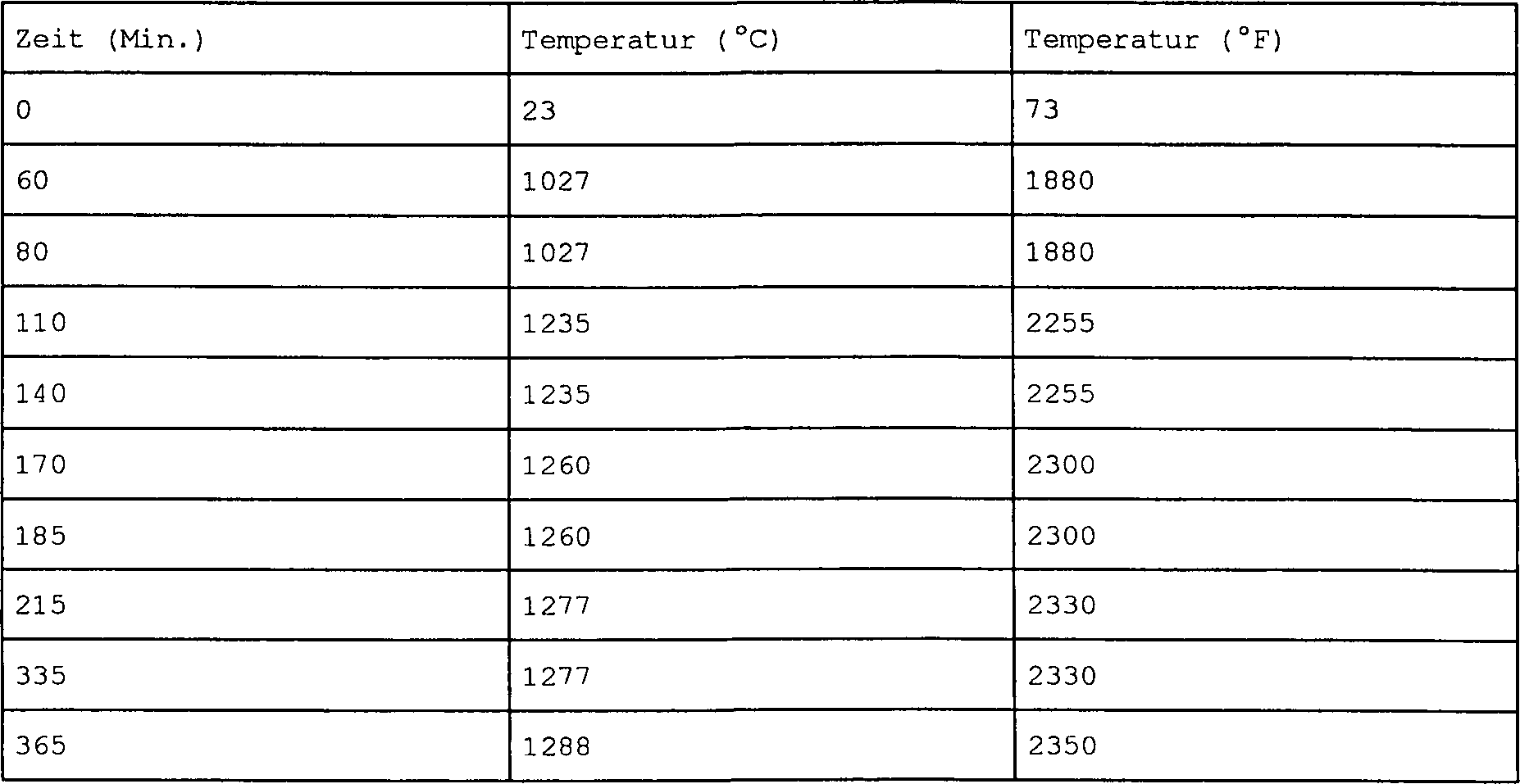

Eine Wärmebehandlung nach dem Verbinden dürfte eine optimale chemische Zusammensetzung und ein optimales Gefüge erzeugen, und zwar nicht nur im Fügebereich, sondern auch in den verbleibenden Anteilen des Basismetalls. Dieser Wärmebehandlungszyklus dürfte die geseigerten Gefüge homogenisieren, die sich nach dem Gießen und Erstarren ergeben, und auch die Ausscheidung und das Wachstum einer optimalen Form bei den verstärkenden γ'-Ausscheidungspartikel bewirken. Für CMSX-4 empfohlene herkömmliche Lösungsglüh- und Wärmebehandlungszyklen können dies in angemessener Weise bewirken. Lösungsglühen ist vorzugsweise eine Wärmebehandlung mit Temperaturanstieg der in Tab. 5 genannten Art. Durch langsames Erhöhen der Temperatur während dieses Zyklus wird Anschmelzen im Wesentlichen vermieden, indem Feststoff-Interdiffusion zugelassen wird, die den örtlichen Schmelzpunkt erhöht. Dieser Prozess ist effizient im Hinblick auf die Homogenisierung monokristalliner Gefüge im Gusszustand, und er bewirkt auch die Homogenisierung der wieder erstarrten Fügezone. Außerdem ist er effektiv, was die Erhöhung der Dispersion des Bors durch das monokristalline Gefüge betrifft, um ein Schmelzen der mit Bor angereicherten Fügelinie zu verhindern. Diese Behandlung hilft beispielsweise, das potenzielle Problem zu vermeiden, dass die nach 4 Stunden bei 1.232°C (2.250°F) entwickelte Fügezone einen Schmelzpunkt haben kann, der unterhalb der Lösungsglüh-Spitzentemperatur von 1.320°C (2.408°F) liegt. Dieser Zyklus kann potenziell verkürzt werden, da die 4 Stunden bei 1.232°C (2.250°F) bereits geholfen haben, das entmischte monokristalline Gefüge zu homogenisieren, und die Diffusion des Bors erfolgt schneller als die Diffusion der metallischen Legierungselemente.A heat treatment after connecting probably produce an optimal chemical composition and an optimal microstructure, not only in the joining area, but also in the remaining shares of the base metal. This Heat treatment cycle might the segregated structures homogenize, which result after pouring and solidifying, and also the excretion and growth of an optimal form in the reinforcing γ 'exudate particles cause. For CMSX-4 recommended conventional Solution annealing and heat treatment cycles can do so in an appropriate way. Solution annealing is preferably a heat treatment with temperature increase of the type mentioned in Tab. 5. By slowly increasing the Temperature during This cycle is essentially avoided by melting Solid interdiffusion is allowed, which is the local Melting point increased. This process is efficient in terms of homogenization monocrystalline structure in the cast state, and he also causes the homogenization of the again solidified joining zone. Furthermore is it effective, what the increase concerning the dispersion of the boron through the monocrystalline structure, to prevent melting of the boron-enriched joint line. These Treatment helps, for example, to avoid the potential problem that after 4 hours at 1,232 ° C (2,250 ° F) developed joining zone may have a melting point below the solution annealing peak temperature of 1,320 ° C (2,408 ° F) lies. This cycle can potentially be shortened since the 4 hours at 1,232 ° C (2,250 ° F) already helped to homogenize the demixed monocrystalline structure, and the diffusion of the boron occurs faster than the diffusion of the metallic alloying elements.
Nach dem Lösungsglühen wird vorzugsweise eine Ausscheidungswärmebehandlungssequenz durchgeführt, um eine optimale Form der verstärkenden γ'-Ausscheidungspartikel zu erzielen. Eine herkömmliche vierstündige Behandlung bei 1.190°C (2.084°F) und eine vierundzwanzigstündige Behandlung bei 898°C (1.650°F) werden durchgeführt, um ca. 0,5 μm große quaderförmige primäre γ'-Ausscheidungspartikel und eine Diffusion kugelförmiger sekundärer und tertiärer γ'-Ausscheidungspartikel in den Matrixkanälen zwischen den Quadern zu erzeugen. Durch Anwendung dieser Wärmebehandlungen, die für die Bearbeitung der monokristallinen Basislegierung entwickelt wurden, werden die Mikrogefüge in den nicht verbundenen Anteilen der gefügten Bauteile zusätzlich zum verbundenen Bereich optimal wärmebehandelt.After the solution annealing, a precipitation heat treatment sequence is preferably performed to obtain an optimum shape of the reinforcing γ'-precipitating particles. A conventional four hour treatment at 1140 ° C (2.084 ° F) and a twenty-four hour treatment at 898 ° C (1,650 ° F) are performed to produce approximately 0.5 μm primary γ'-precipitate particles and diffusion of spherical secondary and tertiary γ'-precipitates in the matrix channels between the blocks. By applying these heat treatments developed for processing the monocrystalline base alloy, the microstructures in the unconnected portions of the joined components are optimally heat treated in addition to the bonded area.
Tab. 6 zeigt, wie die in Tab. 4 genannten Folien bearbeitet werden können, um gleichförmige Bonding-Gefüge an der Fügelinie zu erzielen. Diese Tabelle nennt auch einige der wichtigsten Eigenschaften der Mikrogefüge, die während der Verarbeitung erzeugt werden.Tab. 6 shows how the films mentioned in Tab. 4 can be processed in order to uniform Bonding structure at the joint line to achieve. This table also lists some of the most important features the microstructure, the while the processing are generated.
Zu
Vergleichszwecken stellen die


Gemäß einem Ausführungsbeispiel der vorliegenden Erfindung können vorgefertigte monokristalline Turbinenbauteile durch TLP-Bonding (Transient Liquid Phase Bonding) gefügt werden und qualitativ hochwertige Verbindungen ergeben, wenn ein sehr kleiner, genau gesteuerter Spalt zwischen den Berührungsflächen entsteht. Diese strengen für die Oberflächen geltenden Toleranzanforderungen können durch Oberflächenprofiliertechniken reproduzierbar eingehalten werden. Zudem müssen die durch diese Profiliertechniken erzeugten Spannungen ausreichend niedrig sein, so dass sie nicht zu einer Rekristallisierung der durch Kaltumformung umgeformten Schicht während der anschließenden Wärmebehandlungszyklen, einschließlich Bonding und Wärmebehandlung, führen.According to one embodiment of the present invention, prefabricated monocrystalline turbine components can be joined by TLP (Transient Liquid Phase Bonding) bonding and yield high quality interconnects when a very small, precisely controlled gap exists between the mating surfaces arises. These strict tolerance requirements for the surfaces can be reproducibly met by surface profiling techniques. In addition, the stresses generated by these profiling techniques must be sufficiently low that they do not result in recrystallization of the cold worked formed layer during the subsequent heat treatment cycles, including bonding and heat treatment.
Für TLP-Bonding bestimmte Oberflächen können durch spannungsarmes Schleifen vorbereitet werden, wenn die Oberfläche plan genug ist, oder durch Funkenerosionsbearbeitung (EDM), wenn die elektrischen Bedingungen geeignet sind, um einen Funkenspalt von ca. 0,025 mm (0,001 Zoll) zwischen Werkstück und Werkzeug aufrecht zu erhalten. Bei Bauteilen mit komplexem Profil, die zusammenpassen müssen, kann ein derartiges Oberflächenprofil durch einen Ko-EDM-ECM-Prozess erzielt werden, bei dem eines der zu fügenden Teile als Prozessanode und das andere Teil als Kathode verwendet wird. Anschließend ermöglicht das Bonding, z. B. mit 0,025 mm (0,001 Zoll) dickem Folienmaterial oder vergleichbarer Paste, ein ausreichendes Schmelzen und erneutes Erstarren während des Fügens. Das Material im Fügebereich und das Material neben dem Bonding-Material rekristallisieren nicht während des Fügezyklus oder danach während des Lösungsglühens des monokristallinen Materials bei höheren Temperaturen.For TLP bonding certain surfaces can be prepared by low-tension grinding when the surface plan is enough, or by spark erosion machining (EDM), if the electrical conditions are suitable to a spark gap of Approximately 0.025 mm (0.001 inches) between workpiece and tool upright receive. For components with a complex profile that fit together have to, can such a surface profile through a co-EDM ECM process be achieved, in which one of the parts to be joined as a process anode and the other part is used as a cathode. Subsequently, the bonding allows z. With 0.025 mm (0.001 inch) thick sheet material or the like Paste, sufficient melting and re-solidification during the Joining. The material in the joining area and the material next to the bonding material does not recrystallize while of the joining cycle or afterwards during the solution annealing of monocrystalline material at higher Temperatures.
Rekristallisierung wird vorzugsweise vermieden, indem eine ausreichend kleine Umformungszone während des Formens aufrecht erhalten wird. Wenn kein TLP-Bonding-Prozess stattfindet, wird das Material so geringfügig umgeformt, dass es nicht rekristallisiert oder nur bis zu einer Tiefe rekristallisiert, die der Größenordnung der Dicke einer Bonding-Folie entspricht, z. B. ca. 0,025 mm (0,001 Zoll). Wenn eine Bonding-Folie vorhanden ist, wird die durch Kaltumformung umgeformte Schicht schnell durch den transienten Schmelzprozess abgeschmolzen, und das erneute Erstarren erfolgt dann als monokristal lines Wachstum vom Basismaterial aus. Unter diesen Bedingungskonstellationen tritt keine Rekristallisierung vor dem transienten Schmelzen in den Fügezonen ein. Durch anschließendes Schmelzen und Erstarren werden fehlerfreie Monokristalle erzeugt. Wenn die Monokristalle maschinell bearbeitet und dann im Gusszustand verbunden werden, kann die anschließende Lösungsglühbehandlung bei Temperaturen erfolgen, die bis zu 1.321°C (2.410°F) betragen, ohne dass es dabei zu einer Rekristallisierung in der Fügezone kommt.recrystallization is preferably avoided by leaving a sufficiently small deformation zone during the Forming is maintained. If there is no TLP bonding process, the material becomes so slight reshaped that it is not recrystallized or only up to one Depth recrystallizes, the order of the thickness of a Bonding film corresponds, for. About 0.025 mm (0.001 inches). If a bonding film is present, which is formed by cold forming Layer quickly melted by the transient melting process, and the re-solidification then takes place as a monocrystalline growth from the base material. Under these condition constellations occurs no recrystallization before transient melting in the joining zones one. By subsequent Melting and solidification produces flawless monocrystals. When the monocrystals are machined and then cast can be connected, the subsequent solution annealing treatment at temperatures take place, which up to 1,321 ° C (2,410 ° F) be, without causing a recrystallization in the joint zone comes.
Die monokristalline Legierung CMSX-4 kann im Gusszustand einem Bonding-Prozess unterzogen und anschließend wärmebehandelt werden, wenn die Oberflächen durch spannungsarmes Schleifen gemäß folgendem Prozess bearbeitet wurden: gegossene monokristalline Teile; Gießform entfernen durch leichtes Sandstrahlen (Druckluft mit weniger als 689,4 KPascal (100 psi) und Sandkorngröße max. 90); spannungsarmes Schleifen der Fügeflächen mit einer Flachheits- und Parallelitätstoleranz von < 0,025 mm (0,001 Zoll); Fügen unter Vakuum bei ca. 1.232°C (2.250°F) mit einer Ni-Flex-Folie 110, die 1,3 Gewicht-% Bor enthält, wobei die Temperatur innerhalb von 60 Minuten von 871°C (1.600°F) auf 1.232°C (2.250°F) ansteigt; Lösungsglühen des gefügten Werkstücks unter Vakuum gemäß dem in Tabelle 5 genannten Zyklus (max. Temperatur 1.320°C (2.408°F) für 4 Stunden, Zykluszeit ca. 16 bis 24 Stunden); und Ausscheidungswärmebehandlung (z. B. zweistufige Ausscheidungswärmebehandlung: 4 Stunden bei 1.140°C (2.084°F) und 24 Stunden bei 900°C (1.652°F)).The monocrystalline alloy CMSX-4 can be cast as a bonding process subjected and subsequently heat treated be when the surfaces processed by low stress grinding according to the following process were: cast monocrystalline parts; Remove casting mold by light sandblasting (Compressed air less than 689.4 kPa (100 psi) and sand grain size max. 90); stress-relieved grinding of the joining surfaces with a flatness and parallelism tolerance of <0.025 mm (0.001 inches); Put under vacuum at approx. 1,232 ° C (2,250 ° F) with a Ni-Flex film 110 containing 1.3% by weight boron, wherein the Temperature increases from 871 ° C (1,600 ° F) to 1,232 ° C (2,250 ° F) within 60 minutes; Solution annealing of joined workpiece under vacuum according to the in Cycle (maximum temperature 1,320 ° C (2,408 ° F) for 4 hours, Cycle time approx. 16 to 24 hours); and excretion heat treatment (For example, two-stage precipitation heat treatment: 4 hours at 1140 ° C (2,084 ° F) and 24 hours at 900 ° C (1652 ° F)).
Das spannungsarme Schleifen der Berührungsflächen ergibt nicht nur flache und parallele Oberflächen, die sich auf der Basis sehr strenger Toleranzen bearbeiten lassen (Größenordnung im 0,01 mm-Bereich), sondern auch einen relativ umformungsfreien Oberflächenbereich bei Superlegierungen auf Nickelbasis. Derart geschliffene Oberflächen beinhalten nicht genug gespeicherte Umformkräfte, um eine Rekristallisierung im oberflächennahen Bereich zu bewirken. Wenn diese Oberflächen wärmebehandelt werden, kommt es nicht zu einer Rekristallisierung. Insbesondere dann, wenn das Bonding-Material über der bearbeiteten Oberfläche geschmolzen wird, wird eine Rekristallisierung vermieden. Bei konkurrierenden Prozessen mit Festkörper-γ'-Auflösung, lokaler Oberflächenschmelzung und Rekristallisierung scheint es so, dass die lokale Oberflächenschmelzung der Prozess mit der schnellsten Kinetik ist.The Low-tension grinding of the contact surfaces results not just flat and parallel surfaces that are based on very strict tolerances can be processed (order of magnitude in the 0.01 mm range), but also a relatively deformation-free surface area in superalloys nickel-based. Such ground surfaces do not contain enough stored forming forces, to cause recrystallization in the near-surface region. If these surfaces heat treated become, does not come to a recrystallization. Especially then when the bonding material over the machined surface is melted, a recrystallization is avoided. In competing Processes with solid-state γ'-resolution, local surface melting and recrystallization it seems that the local surface melt the process with the fastest kinetics is.
Alternativ kann die monokristalline Legierung CMSX-4 im Gusszustand gefügt und anschließend wärmebehandelt werden, wenn die Fügeflächen durch Funkenerosionsbearbeitung (EDM) vorbereitet werden, bei der elektrische Bedingungen herrschen, die einen Teilespalt von ca. 0,025 mm (0,001 Zoll) ergeben. Der folgende Prozess kann dabei Anwendung finden: gegossene monokristalline Teile; Gießform durch leichtes Sandstrahlen entfernen (Druckluft mit weniger als 689,4 KPascal (100 psi) und Sandkorngröße max. 90); Ko-EDM-Bearbeitung der Fügeflächen mit ausreichend Spannung und Strom, um einen Funkenspalt von 0,025 mm (0,001 Zoll) zu produzieren; Fügen bei 1.232°C (2.250°F) mit einer Ni-Flex-Folie 110, die 1,3 Gewicht-% Bor enthält, wobei die Temperatur innerhalb von 60 Minuten von 871°C (1.600°F) auf 1.232°C (2.250°F) ansteigt; Lösungsglühen des gefügten Werkstücks unter Vakuum ähnlich dem in Tabelle 9 genannten Zyklus (max. Temperatur 1.320°C (2.408°F) für 4 Stunden, Zykluszeit ca. 16 bis 24 Stunden); und Ausscheidungswärmebehandlung (z. B. zweistufige Ausscheidungswärmebehandlung: 4 Stunden bei 1.140°C (2.084°F) und 24 Stunden bei 900°C (1.652°F)).Alternatively, the monocrystalline alloy CMSX-4 may be as-cast and then heat treated as the mating surfaces are prepared by EDM machining under electrical conditions giving a pitch of about 0.025 mm (0.001 inches). The following process can be used: cast monocrystalline parts; Mold by light weight Remove sandblast (compressed air less than 689.4 kPa (100 psi) and sand grain size 90 maximum); Co-EDM machining the bonding surfaces with sufficient voltage and current to produce a spark gap of 0.025 mm (0.001 inches); Add at 1,232 ° C (2,250 ° F) with a Ni-Flex sheet 110 containing 1.3% by weight of boron, with the temperature ranging from 871 ° C (1600 ° F) to 1232 ° C within 60 minutes ( 2.250 ° F) increases; Solution annealing of the joined workpiece under vacuum similar to the cycle shown in Table 9 (maximum temperature 1320 ° C (2,408 ° F) for 4 hours, cycle time approximately 16 to 24 hours); and precipitation heat treatment (eg, two-stage precipitation heat treatment: 4 hours at 1140 ° C (2084 ° F) and 24 hours at 900 ° C (1652 ° F)).
Diese Prozesse vermeiden in so ausreichender Weise eine Umformung, dass eine Rekristallisierung des Materials nahe der Fügefläche verhindert wird. Diese Eigenschaft ist erforderlich für die Produktion akzeptabler TLP-Bonding-Verbindungen bei monokristallinen Materialien wie CMSX-4. Neben diesen Bearbeitungsprozessen können auch belastungsärmere Prozesse wie mechanisches Schleifen mit Feinschleifmitteln der Korngröße 600 und Polieren, z. B. mit Diamantschleifmitteln, mit einer Oberflächengüte von 0,25 μm angewendet werden, um Oberflächen zu gewinnen, die eine ausreichend geringe Umformung aufweisen und sich zum Fügen eignen.These Processes so sufficiently avoid forming that Recrystallization of the material near the joint surface is prevented. These Property is required for the production of acceptable TLP bonding compounds in monocrystalline Materials like CMSX-4. Besides these editing processes can also load poorer Processes such as mechanical grinding with fine abrasives of grain size 600 and Polishing, z. As with diamond abrasives, applied with a surface quality of 0.25 microns be to surfaces to win, which have a sufficiently low deformation and to join suitable.
Auf Grund ihrer Größe können bei landgestützten Turbinen sehr kleine Verschiebungen gegenüber den Designspezifikationen bereits große absolute Abweichungen von den gewünschten Teileprofilen bewirken. Während diese Abweichungen bei ungeteilten Gussstücken erheblich sind, werden sie bei der Produktion gefügter Teile kritisch, da sie Einfluss auf die relative Zurichtung zwischen den Teilen haben. In der Praxis können sehr kleine relative Verschiebungen zwischen zwei Teilen sehr große Spalte erzeugen, die durch den Bonding-Prozess unzureichend oder unvollständig ausgefüllt werden. Um gefügte Teile akzeptabler Qualität zu produzieren, ist es wünschenswert, den Gießprozess zu steuern, um solche Spalte einzudämmen, oder die Bearbeitung nach dem Gießen so zu modifizieren, dass derartige Spalte korrigiert werden. Die vorgeschlagene Prozesssequenz bietet eine einfache Serie von Prozessen, die die Steuerung derartiger Spalte und effiziente Bonding-Prozeduren ermöglichen.On Reason of their size can be land-based Turbines very small shifts compared to the design specifications already big cause absolute deviations from the desired part profiles. While these deviations are significant in undivided castings they are more involved in production Parts critically, as it affects the relative finishing between have the parts. In practice, very small relative shifts between two parts very big Create gaps that are insufficiently or incompletely filled by the bonding process. To be joined Parts of acceptable quality to produce, it is desirable the casting process to control such gaps, or editing after the pouring to modify so that such gaps are corrected. The proposed process sequence provides a simple series of processes the control of such column and efficient bonding procedures enable.
Die Prozesssequenz vermeidet eine schädliche Rekristallisierung. Zu einer Rekristallisierung kann es kommen, wenn Metallbearbeitungsprozesse und nachfolgende Wärmebehandlungszyklen zusammen genug gespeicherte Kaltumformkräfte und ausreichend Wärmeenergie erzeugen, um örtlich die Bildung neuer Körner zu bewirken. Bei Monokristallen auf Nickelbasis, die bei der Herstellung von Turbinenkomponenten verwendet werden, kann zu dieser Bearbeitung Biegen und Kaltprofilieren, maschinelle Bearbeitung mit Werkzeugmaschinen und sogar zu heftiges Reinigen durch Sandstrahlen gehören. Der durch diese Prozesse verursachte Schaden kann eine Rekristallisierung bewirken, wenn diese Prozesse vor dem Lösungsglühen bei ca. 1.316°C (2.400°F) stattfinden, das bei derartigen Monokristallen erforderlich ist. In Obereinstimmung mit einem bevorzugten Ausführungsbeispiel der vorliegenden Erfindung erfordern Prozesse zur Herstellung vorgefertigter Teile aus Gussstücken die sequenzielle Anordnung der Reinigungs-, Bonding- und Wärmebehandlungszyklen. Bei gefügten Teilen ist es wünschenswert, im Wesentlichen alle Reste der Gießform vor dem Fügen zu entfernen. Zudem erfolgt das Fügen vorzugsweise vor dem Lösungsglühen. Daher ist es von entscheidender Bedeutung, die Teilebearbeitungsschritte zu steuern und in der richtigen Sequenz anzuordnen, um eine mögliche Rekristallisierung zu vermeiden. Der vorliegende Prozesspfad begrenzt den Grad der Umformung, der durch die Bearbeitung der Teile entsteht, und sieht einen Wärmebehandlungszyklus vor, der für optimierte Eigenschaften in der Fügezone wie im Monokristall weiter entfernt von der Fügung sorgt.The Process sequence avoids harmful recrystallization. Recrystallization can occur when metalworking processes and subsequent heat treatment cycles together enough stored cold forming forces and sufficient heat energy generate locally the formation of new grains too cause. For nickel-based monocrystals used in the manufacture Can be used by turbine components, this process Bending and cold profiling, machining with machine tools and even include excessive cleaning by sandblasting. Of the Damage caused by these processes can be a recrystallization when these processes take place before solution annealing at about 1316 ° C (2400 ° F), which is required in such monocrystals. In agreement with a preferred embodiment The present invention requires processes for the production of prefabricated Parts of castings the sequential arrangement of the cleaning, bonding and heat treatment cycles. Attached Sharing it is desirable essentially remove all remnants of the mold before joining. moreover the joining takes place preferably before the solution heat treatment. Therefore It is crucial to the parts processing steps to steer and arrange in the right sequence to a possible recrystallization to avoid. The present process path limits the degree of Forming, which results from the machining of the parts, and sees a heat treatment cycle before that for optimized properties in the joining zone as in monocrystal farther away from the addition provides.
Durch sorgfältiges, druckarmes Reinigen, gesteuerte Hochtemperaturumformung und Ko-EDM-Bearbeitung der Passflächen bietet der Prozess eine kostengünstige Möglichkeit, um monokristalline Turbinenschaufeln aus mehreren Gussteilen herzustellen.By careful, Low-pressure cleaning, controlled high-temperature forming and co-EDM processing the mating surfaces the process offers a cost effective Possibility, to produce monocrystalline turbine blades from multiple castings.
Eine monokristalline Turbinenschaufel kann aus mehreren gesondert gegossenen Teilen mit Hilfe folgender Sequenz vorgefertigt werden: mechanisches Reinigen der Teile vor dem Fügen; Verbinden der Teile vor der Hochtemperatur-Lösungsglühbehandlung; Vermeiden von Rekristallisierung während der Wärmebehandlung, zu der es durch örtliche Umformung der Oberfläche während des Reinigens kommen kann; optimierte Zurichtung der zu fügenden Teile (z. B. mit einer Toleranz von < 0,025 mm (0,001 Zoll) quer zur gefügten Fläche); und Entwickeln optimierter Teileprofile über die gesamte Länge der Schaufel. Eine integrierte Sequenz, die das TLP-Bonding der bearbeiteten Teile beinhaltet, erfüllt diese Ziele.A monocrystalline turbine blade can be prefabricated from several separately cast parts using the following sequence: mechanical cleaning of the parts prior to joining; Joining the parts before the high-temperature solution annealing treatment; Avoid recrystallization during heat treatment action which may occur due to local deformation of the surface during cleaning; optimized dressing of the parts to be joined (eg with a tolerance of <0.025 mm (0.001 inches) across the joined surface); and developing optimized part profiles over the entire length of the blade. An integrated sequence incorporating TLP bonding of machined parts meets these goals.
Vorzugsweise werden die gegossenen Teile gereinigt, um sie genau der gewünschten Form entsprechen zu lassen, ohne eine Umformung zu bewirken, die während der nachfolgenden Wärmebehandlung eine Rekristallisierung nach sich ziehen könnte. Obwohl das Reinigen der monokristallinen Teile von Gießformresten herkömmlicherweise nach dem Lösungsglühen erfolgt, um eine Rekristallisierung zu vermeiden, werden die Komponenten hier vor dem Fügen gereinigt. Da optimale Eigenschaften erzielbar sind, wenn das Fügen vor dem Lösungsglühen erfolgt, sollte diese Reinigung dem Lösungsglühen vorausgehen. Wegen der Gefahr, dass eine Rekristallisierung erfolgt, sollte die während des Reinigens durch mechanische Abrasion bewirkte Umformung minimiert werden. Diese Anforderung verlangt nach spannungsarmer Reinigung.Preferably The cast parts are cleaned to exactly the one you want Form without causing a deformation, the while the subsequent heat treatment could recrystallize. Although cleaning the monocrystalline parts of foundry mold residues conventionally after solution heat treatment, to avoid recrystallization, the components become here before joining cleaned. Since optimal properties are achievable when joining before the solution annealing takes place This cleaning should precede solution heat treatment. Because of the risk of recrystallization, the while cleaning caused by mechanical abrasion minimized become. This requirement requires low-voltage cleaning.
Bei CMSX-4 hat eine Abrasionsreinigung, bei der die Abrasionspartikelgröße auf eine Körngröße < 60 und der Druckwert der (Treib-) Druckluft auf 620,5 KPascal (90 psi) begrenzt wird, ergeben, dass eine Rekristallisierung vermieden wird, wenn die Monokristalle anschließend einer Lösungsglühbehandlung gemäß dem in Tabelle 5 genannten Zyklus unterzogen werden.at CMSX-4 has an abrasion cleaning, in which the abrasion particle size on one Grain size <60 and the pressure value the (motive) compressed air is limited to 620.5 KPascal (90 psi), show that recrystallization is avoided when the monocrystals subsequently a solution annealing treatment according to the in Table 5.
Die Reinigung der künftigen Innenflächen des Teils ist notwendig, und die Reinigung der Außenflächen ist in allen Bereichen erforderlich, die in Kontakt mit der mechanischen Spannvorrichtung sind, die einen eng geschlossenen Spalt quer zu den Fügeflächen sicherstellen soll.The Cleaning the future inner surfaces of the part is necessary, and the cleaning of the outside surfaces is required in all areas that are in contact with the mechanical Clamping device are those that have a tightly closed gap across Ensure the joining surfaces should.
Das Problem, bei langen Gussstücken gute Teileprofile zu gewährleisten, kann entweder durch Verbesserung der Gusspräzision oder durch mechanische Bearbeitung der Gussteile gelöst werden. Die kontinuierliche Anpassung der Gießform, um Gieß- und thermische Verschiebungen zu berücksichtigen, bietet ein Mittel, um toleranzkonforme Profilteile zu gewinnen, die für systematische und makroskopische Verschiebungen des Teils und der Gießform geeignet sind. Änderungen des Teils und der Gießform berücksichtigen jedoch nicht die Schwankungen und erratischen, von Guss zu Guss zu beobachtenden Abweichungen gegenüber dem gewünschten Profil. Da winzige Abweichungen eine große absolute Verschiebung vom gewünschten Profil über die Länge von Bauteilen großer landgestützter Turbinen bewirken können, sollten diese Schwankungen und erratischen Abweichungen von Guss zu Guss durch andere Mittel ausgeglichen werden. Während polykristalline Legierungen mechanisch bei Zimmertemperatur gerichtet werden können, werden bei der herkömmlichen Bearbeitung monokristalliner Legierungen derartige Umformprozesse vermieden, da dies die Gefahr einer Rekristallisierung mit sich bringt. Es ist jedoch ggf. möglich, Monokristalle von Superlegierungen auf Nickelbasis mit einer Dehnung von ca. 40% zu biegen, ohne dass eine Rekristallisierung eintritt, wenn die Temperatur und die Umformgeschwindigkeit wirksam kontrolliert werden. Dieser Prozess kann zum Strecken von Teilen angewendet werden, z. B. angemessene Formänderungen um ca. 2 bis 3%, wobei eine schädliche Rekristallisierung nach anschließender Wärmebehandlung vermieden wird.The Problem with long castings to ensure good part profiles can either by improving the casting precision or by mechanical Machining of the castings solved become. Continuous adaptation of the casting mold to casting and thermal To consider shifts, offers a means for obtaining tolerance-compliant profile parts, the for systematic and macroscopic shifts of the part and the mold are suitable. amendments of the part and the mold consider but not the fluctuations and erratic, from cast to font observed deviations from the desired profile. There tiny Deviations a big one absolute shift of the desired Profile over the length of components large land-based Can cause turbines should these fluctuations and erratic deviations from casting to be balanced by other means. While polycrystalline Alloys can be mechanically aligned at room temperature in the conventional Processing monocrystalline alloys such forming processes avoided, since this involves the risk of recrystallization brings. However, it may be possible Monocrystals of nickel-base superalloys with an elongation about 40% without recrystallization, when the temperature and the forming speed are effectively controlled become. This process can be used to stretch parts z. B. appropriate shape changes by about 2 to 3%, being a harmful Recrystallization is avoided after subsequent heat treatment.
Das Problem der Produktion minimaler und konsistenter Spalte zwischen den zu verbindenden Teilen kann in Übereinstimmung mit der vorliegenden Erfindung dadurch gelöst werden, dass die Teile mit Übermaß gegossen werden und dann das überschüssige Material durch maschinelle Bearbeitung der Berührungsflächen in koordinierter Weise abgetragen wird. Die Berührungsflächen sollten dann mit einer Toleranz von ca. 0,025 mm (0,001 Zoll) bündig sein, so dass ein gutes TLP-Bonding sichergestellt wird. Durch Ko-EDM-Bearbeitung können nicht nur die Berührungsflächen der zu verbindenden Teile fertig bearbeitet werden, sondern auch eine ausreichend hohe Oberflächengüte erzielt werden. Wenn die Umschmelzschicht gesteuert hergestellt wird, kann zudem eine Rekristallisierung des Monokristalls nach dem Verbinden vermieden werden. Bei der Ko-EDM-Bearbeitung wird von beiden Seiten der Werkstücks Material abgetragen, da jedes Werkstück abwechselnd als Kathode und als Anode verwendet wird. Die Teile können mit Übermaß gegossen werden, um mehr Toleranz für den Materialabtrag zu erhalten. Die Steuerung des elektrischen Stroms während des Materialabtrags steuert nicht nur den Spalt zwischen den beiden Teilen (und dessen Präzision), sondern auch die Tiefe der Umschmelzschicht. Die Tiefe dieser Umschmelzschicht sollte minimiert werden, um Oberflächenrisse und oberflächennahe Risse sowie Rekristallisierung nach der anschließenden Wärmebehandlung zu vermeiden. Das Halten des EDM-Stroms auf einem Wert, bei dem ein ca. 0,025 mm (0,001 Zoll) großer Spalt zwischen den Werkstücken entsteht, begrenzt die Umschmelzschicht auch so, dass sie ausreichend klein ist und so während der anschließenden TLP-Bonding-Phase abgeschmolzen wird.The Problem of producing minimal and consistent column between The parts to be joined may be in accordance with the present Invention solved thereby be that the parts are poured with oversize and then the excess material by machining the contact surfaces in a coordinated manner is removed. The contact surfaces should be then flush with a tolerance of about 0.025 mm (0.001 inches), so that a good TLP bonding is ensured. By co-EDM processing can not just the touch surfaces of the finished parts to be joined, but also a achieved sufficiently high surface quality become. If the remelt layer is manufactured under controlled conditions, also a recrystallization of the monocrystal after bonding be avoided. In the case of co-EDM editing will be from both sides the workpiece Material removed, as each workpiece alternately as a cathode and used as an anode. The parts can be poured with excess to get more Tolerance for to receive the material removal. The control of the electric current while The material removal not only controls the gap between the two Sharing (and its precision), but also the depth of the remelt layer. The depth of this remelt layer should be minimized to surface cracks and near-surface To avoid cracks and recrystallization after the subsequent heat treatment. Keeping the EDM current at a value where an approx. 0.025 mm (0.001 inches) in size Gap between the workpieces arises, limits the remelt layer so that it is sufficient is small and so on the subsequent TLP bonding phase is melted off.
Das Einplanen von ca. 0,762 mm (0,030 Zoll) Übermaß quer zur Berührungsfläche beim Gussstück und eine Ko-EDM-Bearbeitung auf einen Spalt von 0,025 mm (0,001 Zoll) ermöglicht jene ausgezeichnete Teilepassung, die für das TLP-Bonding notwendig ist.The Schedule approximately 0.762 mm (0.030 inch) oversize across the touch surface when Casting and co-EDM machining to a 0.025 mm (0.001 inch) gap allows those excellent part fitting necessary for TLP bonding is.
Um die Teilezurichtung während des Verbindens beizubehalten, müssen die Teile ggf. in eine Spannvorrichtung gespannt werden, wobei die Belastung quer zur Fügefläche aufrecht erhalten wird, während die Teile im Ofen erwärmt werden. Die Spannvorrichtung muss während des Bonding-Prozesses hohen Temperaturen widerstehen. Verwendet werden können dazu Schnellspannvorrichtungen aus Molybdän, die Spaltschließ-Presslasten auf die Teile auf Grund unterschiedlicher thermischer Ausdehnung ausüben.Around the parts finishing during of maintaining the link the parts may be clamped in a tensioning device, wherein the Load across the joint surface upright is obtained while the parts are heated in the oven become. The tensioning device must be during the bonding process withstand high temperatures. Can be used to Molybdenum quick-release devices, the gap-closing pressing loads on the parts due to different thermal expansion exercise.
Vor dem Zusammenbau der Teile in der Spannvorrichtung kann ein Bonding-Medium (Folie oder Paste) auf die Fügefläche aufgebracht werden. Die Spannvorrichtung stellt nicht nur sicher, dass der Spalt schließt, bevor die Teile in den Ofen kommen, sondern hält den Spalt auch während der Wärmebehandlung aufrecht. Der Wärme- und Druckzyklus für das Bonding kann bei Bedarf so gesteuert werden, dass eine Gasabgabe (z. B. von Bindemittelsubstanzen in der Bonding-Paste) berücksichtigt wird. Anschließend können die Teile mit Hilfe des für monokristallines Material genannten Zyklus verbunden werden.In front the assembly of the parts in the clamping device can be a bonding medium (Foil or paste) applied to the joint surface become. The tensioner not only ensures that the gap closes before the parts come into the oven but keeps the gap even during the heat treatment upright. The heat and printing cycle for if necessary, the bonding can be controlled so that a gas delivery (eg of binder substances in the bonding paste) becomes. Subsequently can the parts with the help of for monocrystalline material called cycle.
Ein bevorzugter Prozess bzw. eine bevorzugte Sequenz zur Entwicklung optimaler allgemeiner Eigenschaften im Teil sieht wie folgt aus: Gießen (Züchten) des monokristallinen Teils der Schaufel mit Übermaß (ca. 0,762 mm (0,030 Zoll) überschüssiges Material) senkrecht zur Fügefläche, um ausreichend Material für den Materialabtrag während der Zurichtungsbearbeitung zu haben; Reinigen und Entfernen der keramischen Gießform mittels übertragener Vibrationen (z. B. manuell auf ein überflüssiges Teil des Gussstücks wie etwa Keim, Rampe oder Speiser mit einem Hammer schlagen) und anklebende Keramikstücke durch Sandstrahlen bei niedrigem Druck, z. B. < 620,5 KPascal (90 psi) und Sandkorngröße < 120, reinigen; Ko-EDM-Bearbeitung der Teile, um gute Zurichtung über die gesamten Fügeflächen zu erzielen; Fügeflächen mit Alkohol (Methyl- oder Äthylalkohol), Azeton oder in Wasser aufgelöster Seife reinigen, um nach der EDM-Bearbeitung verbleibende kohlenstoffhaltige Ablagerungen (d. h., den Karbonfilm, der sich während der EDM-Bearbeitung auf der monokristallinen Fläche bilden kann) zu entfernen; Oberfläche beim Reinigen leicht mit einer Borstenbürste abbürsten, um die Oberfläche der Kohlenstoffschicht aufzubrechen und das Abfließen der Ablagerungen in die Reinigungsflüssigkeit zu unterstützen; ein Bonding-Medium in den Spalt zwischen den Teilen bringen – entweder zurechtgeschnittene Folie oder aufzutragende Paste, um eine Bonding-Füllung von ca. 0,025 mm (0,001 Zoll) des TLP-Bonding-Mediums zu erhalten; Teile in eine Spannvorrichtung einspannen, die gesteuerte Lasten quer zu den Fügeflächen ermöglicht, um normale Lasten auf Anteile der Außenflächen des Teils mit Hilfe von Stiften zu beaufschlagen, die senkrecht zur Fügeebene angeordnet sind, und zwar so, dass sie maximales Schließen des Spalt über das gesamte Teil ergeben; unter Hochvakuum fügen (mehr als 10–5 τ) gemäß dem Temperaturzyklus, der für monokristalline Legierungen angegeben wird (bei CMSX-4: 4 Stunden lang 1.232°C (2.250°F)); Spannvorrichtung nach Abkühlen auf Zimmertemperatur wieder entfernen; Lösungsglühen gemäß dem herkömmlicherweise für diese Legierung angewendeten Behandlungstyp: Reinigen der Außenflächen ist optional möglich (obwohl dies auch nach der Ausscheidungswärmebehandlung möglich ist); 4 Stunden lang Ausscheidungswärmebehandlungprozess zur Optimierung der Eigenschaften (bei CMSX-4 ein zweistufiger Ausscheidungswärmebehandlungprozess bei 1.140°C (2.084°F) und 24 Stunden lang bei 900°C (1.652°F)); und mechanisches Abrichten der Turbinenschaufel auf Fertigmaß und anschließendes Polieren.A preferred process or sequence for developing optimal general properties in the part is as follows: casting (growing) the monocrystalline part of the over-sized blade (0.030 inch excess material) perpendicular to the mating surface to provide sufficient material to have material removal during finishing processing; To clean and remove the ceramic mold by means of transmitted vibrations (eg, hammering manually on an excess part of the casting, such as a germ, ramp or feeder with a hammer) and adhering ceramic pieces by sandblasting at low pressure, e.g. B. <620.5 KPASCAL (90 psi) and sand grain size <120; Co-EDM machining of the parts to achieve good finish over the entire joint surfaces; Clean bonding surfaces with alcohol (methyl or ethyl alcohol), acetone, or soap dissolved in water to remove carbonaceous deposits (ie, the carbon film that may form on the monocrystalline surface during EDM machining) after EDM machining; Brush the surface lightly with a bristle brush during cleaning to break up the surface of the carbon layer and assist the drainage of the deposits into the cleaning fluid; place a bonding medium in the gap between the parts - either cut foil or paste to be applied to obtain a bonding fill of about 0.025 mm (0.001 inches) of the TLP bonding medium; Clamping parts into a jig that allows controlled loads across the mating surfaces to apply normal loads to portions of the outer surfaces of the part by means of pins disposed perpendicular to the mating plane such that they maximally close the gap across the mating surface entire part result; under high vacuum (more than 10 -5 τ) according to the temperature cycle reported for monocrystalline alloys (for CMSX-4: 1,232 ° C (2,250 ° F) for 4 hours); Remove the clamping device after cooling to room temperature; Solution annealing according to the treatment type conventionally used for this alloy: cleaning of the outer surfaces is optionally possible (although it is possible even after the precipitation heat treatment); Precipitation heat treatment process for 4 hours to optimize properties (in CMSX-4 a two-stage precipitation heat treatment process at 1140 ° C (2084 ° F) and 24 hours at 900 ° C (1652 ° F)); and mechanically truing the turbine blade to finished size and then polishing.
In einem zusätzlichen Schritt können die Teile optional durch Biegen mittels eines Prozesses gerichtet werden, der keine Rekristallisierung hervorruft. Dieser Prozess beinhaltet spannungsarme Hochtemperaturumformung (vergleichbar mit superplastischer Um formung), die eine Verschiebung der Teile bewirkt, ohne zugleich einen so starken Umformschaden hervorzurufen, dass es zu einer Rekristallisierung kommt.In an additional Can step the parts are optionally directed by bending by means of a process, which does not cause recrystallization. This process involves Low-tension high-temperature deformation (comparable to superplastic To formung), which causes a displacement of the parts, without at the same time to cause such a severe deformation damage that it recrystallizes comes.
Auf diese Weise wird ein integrierter Prozesspfad für das Verbinden monokristalliner Teile zur Herstellung kompletter Turbinenschaufeln gewonnen. Die sequenzialisierten Prozessschritte bieten die Materialqualität und die Wärmebehandlungsschritte, mit denen qualitativ hochwertige monokristalline Komponenten gefertigt werden können, die den hohen Temperaturen widerstehen, die bei Komponenten in Gasturbinenmaschinen anfallen. Das Verfahren deckt die gesamte Verarbeitung der Teile ab und ermöglicht eine optimale Fügespaltzurichtung und Verarbeitung sowie optimale Teileprofile.In this way, an integrated process path for connecting monocrystalline parts to produce complete turbine blades is obtained. The sequentialized process steps provide the material quality and heat treatment steps that can be used to produce high quality monocrystalline components that withstand the high temperatures found in gas turbine engine components incurred. The process covers the entire processing of the parts and allows for optimal joint splitting and processing as well as optimum part profiles.
Zusammengefasst läuft dieser Prozess vorzugsweise wie folgt ab: Komponenten im Gusszustand, die aus ihren keramischen Gießschalen durch leichtes Sandstrahlen entfernt werden, Ko-EDM-Bearbeitung der zu fügenden Teile, um genaue Zurichtung zu gewährleisten, effizientes Fügen der Teile im Gusszustand und anschließende Lösungsglühsowie zuletzt Ausscheidungswärmebehandlung der Teile. Eine Änderung dieser Sequenz ist ebenfalls möglich, wobei eine gesteuerte Warmumformung der vorgefügten Teile zur Anwendung kommt, um Profil und Zurichtung zu optimieren.Summarized this one is running Process preferably as follows: as cast components their ceramic casting bowls be removed by light sandblasting, co-EDM machining the one to be joined Parts to ensure accurate dressing, efficient joining of As cast parts followed by solution annealing and finally exotherm heat treatment Of the parts. A change this sequence is also possible using controlled hot working of the pre-assembled parts, to optimize profile and dressing.
BEISPIELEEXAMPLES
Die Wirkung der chemischen Zusammensetzung der Bonding-Folie und der Wärmebehandlungen auf das Mikrogefüge und die mechanischen Eigenschaften wurden experimentell geprüft. Anfangs wurden verschiedene chemische Bonding-Folien-Zusammensetzungen und Wärmebehandlungsprozesse angewendet, um Proben für die metallografische Untersuchung zu gewinnen. Die Prozesse, die die homogenste chemische Zusammensetzung und das homogenste Mikrogefüge quer zur Fügelinie und im gesamten Basismaterial ergaben, wurden dann zur weiteren Bewertung durch Prüfen der Zug- und Kriechfestigkeit ausgesucht.The Effect of the chemical composition of the bonding foil and the heat treatments on the microstructure and the mechanical properties were tested experimentally. At first have been various chemical bonding film compositions and Heat treatment processes applied to samples for to win the metallographic investigation. The processes that the most homogeneous chemical composition and the most homogeneous microstructure across to the joint line and throughout the base material, then became further Evaluation by testing the tensile and creep strength selected.
CMSX-4-Basismaterial wurde im Gusszustand in Form monokristalliner Brammen mit den Maßen 9,5 × 76,2 × 152,4 mm (0,375 × 3 × 6 Zoll) geliefert. Als Bonding-Medium wurden 50 μm (0,002 Zoll) dicke Folien benutzt, die im Handel angeboten werden.CMSX-4 base material was cast as monocrystalline slabs measuring 9.5 × 76.2 × 152.4 mm (0.375 × 3 × 6 inches) delivered. The bonding medium used was 50 μm (0.002 inch) thick films. which are offered in the trade.
Die Boranteile der Bonding-Folien sind eigentlich als „B-Prozentbereiche" anzusehen, da zwei der Folien in mehreren Formen mit leicht unterschiedlichen Boranteilen geliefert wurden: Ni-Flex 110 wurde geliefert mit 1,3%, 1,7% und 2,5% Borgehalt, und Ni-Flex 120 wurde geliefert mit 1,5%, 1,7% und 1,9% Borgehalt. Zudem war zu beachten, dass die Borkonzentration nicht über die gesamte Tiefe der Folie einheitlich war, da die Folien mittels eines Diffusionsprozesses hergestellt worden waren. Die in der Tabelle genannten Borgehaltsangaben sind also als mittlere Konzentrationen über die Tiefe der Folie zu verstehen.The Boron parts of the bonding foils are actually to be regarded as "B percentages" because two the films in several forms with slightly different borane proportions Ni-Flex 110 was delivered with 1.3%, 1.7% and 2.5% boron content, and Ni-Flex 120 was delivered with 1.5%, 1.7% and 1.9% boron content. In addition was Note that the boron concentration does not exceed the entire depth of the film was uniform, because the films by means of a diffusion process had been made. The boron information given in the table are therefore too high as average concentrations across the depth of the film understand.
Die einzelnen Proben wurden für die metallografischen und mechanischen Versuchsphasen des Programms in ähnlicher Weise vorbereitet. Die einzigen Unterschiede bestanden darin, dass die größeren Proben als mechanische Versuchsproben benutzt wurden und dass die verfeinerten Oberflächenvorbereitungsmethoden, die während der Anfangsphase des Programms entwickelt wurden, für das Fügen der Proben bei den mechanischen Versuchen zur Verfügung standen. Die Fügeflächen der Proben für die metallografischen Untersuchungen wurden durch spannungsarmes Schleifen, Polieren mit Poliermitteln der Korngrößen 120, 320 bzw. 600 oder Elektropolitur fertig bearbeitet, während die Fügeflächen der Proben für die mechanischen Versuche nur durch spannungsarmes Schleifen fertig bearbeitet wurden.The individual samples were for the metallographic and mechanical experimental phases of the program in a similar way Way prepared. The only differences were that the larger samples than mechanical test samples were used and that the refined ones Surface preparation methods the while The initial phase of the program was developed for joining the program Samples were available during the mechanical tests. The joining surfaces of the Samples for the metallographic investigations were carried out by low stress Grinding, polishing with polishers of grain sizes 120, 320 or 600 or Electropolishing finished, while the joining surfaces of the samples for mechanical Experiments were only finished by stress-relieved grinding.
Um Probleme durch Fehlorientierung der Kristalle in den Proben zu vermeiden, wurden alle Fügeproben durch Schneiden und erneutes Zusammenfügen einzelner Monokristalle vorbereitet, d. h. eine monokristalline Originalbramme wurde senkrecht in Kristallwachstumsrichtung in Abschnitte getrennt, und die so erzeugten Flächen wurden nach der Fertigbearbeitung der Oberflächen wieder miteinander verbunden. Alle anfänglichen Trennarbeiten an den Proben erfolgten mittels einer metallografischen Siliziumkardid-Schleifscheibe, die auch dazu diente, die kleineren metallografischen Proben aus der Brammenbreite zu gewinnen. Die gefügten Proben, die für die metallografische Evaluierung dienten, waren Parallelepipede (Spate) mit den Circa-Maßen 13 × 13 × 13 mm (0,5 × 0,5 × 0,5 Zoll), während die Proben für die mechanischen Versuche mit dem Maßen 9,5 × 76,2 × 38 mm (0,375 × 3 × 1,5 Zoll) gefertigt wurden, d. h. Brammen mit normaler Breite und einem Viertel der Normalhöhe.Around Avoid problems due to misorientation of the crystals in the samples were all joining samples by cutting and reassembling individual monocrystals prepared, d. H. a monocrystalline original slab became vertical separated into sections in the crystal growth direction, and the like generated areas were reconnected after finishing the surfaces. All initial Separation work on the samples was carried out by means of a metallographic Silicon carded grinding wheel, which also served the smaller to gain metallographic samples from the slab width. The joined samples, the for the metallographic evaluation served were parallelepipeds (Spade) with the approximate dimensions 13 × 13 × 13 mm (0.5 x 0.5 x 0.5 inches), while the samples for mechanical tests measuring 9.5 × 76.2 × 38 mm (0.375 × 3 × 1.5 inches) were manufactured, d. H. Slabs with normal width and a quarter the normal height.
Das Bonding wurde in einem Hochvakuumofen durchgeführt, in dem die Proben durch eine Molybdän-Spannvorrichtung festgehalten wurden. Vor dem Verbinden wurden die Folien und die Monokristalle vollständig entfettet. Die Bonding-Folie wurde exakt zugeschnitten, so dass sie genau dem Querschnitt der Fügung entsprach und zwischen die beiden Berührungsflächen passte, als die Proben in der Spannvorrichtung zusammengefügt wurden. Diese Spannvorrichtung sorgte nicht nur für das Fluchten der Monokristalle, sondern entwickelte auch gesteuerte Lasten in der Größenordnung von 0,1 bis 1,0 MPa (15–150 psi) quer zur Fügelinie während des Aufheizens des Ofens sowie während der Bonding-Temperaturen.The Bonding was performed in a high vacuum oven in which the samples passed through a molybdenum chuck were detained. Before joining, the slides and the Monocrystals completely degreased. The bonding foil was cut exactly, so that they are exactly the cross section of the coincidence corresponded and fit between the two interfaces than the samples were assembled in the clamping device. This tensioning device not only made for the alignment of monocrystals, but also developed controlled Loads of the order of magnitude from 0.1 to 1.0 MPa (15-150 psi) across the joint line while the heating of the oven as well as during the bonding temperatures.
Die CMSX-4-Brammen wurden entweder im Gusszustand oder nach dem Lösungsglühen verbunden. Die Lösungsglühbehandlung, die für diese Legierung typisch ist, wurde in einer Schutzgasatmosphäre durchgeführt und beinhaltete einen stufenförmigen Zyklus bis max. 6 Stunden Dauer bei 1.593 K (1.320°C, 2.408°F). Die Abkühlgeschwindigkeit nach dem Lösungsglühen betrug ca. 433 K/min (160°C/min, 300°F/min). Was das Verbinden der Monokristalle betrifft, so wurden zwei verschiedene Bonding-Zyklen untersucht. Zyklus A wurde 4 Stunden lang bei 1.543 K (1.270°C, 2.318°F) durchgeführt, während Zyklus B 4 Stunden lang bei 1.505 K (1.232°C, 2.250°F) durchgeführt wurde. Beide Bonding-Zyklen fanden in einem Vakuum von mind. 1,3 × 10⁻² Pa (1 × 10⁻⁵ torr) statt.The CMSX-4 slabs were bonded either as cast or after solution heat treatment. The solution heat treatment, which is typical for this alloy, was carried out in a protective gas atmosphere guided and included a stepped cycle to max. 6 hours duration at 1,593 K (1,320 ° C, 2,408 ° F). The cooling rate after solution annealing was about 433 K / min (160 ° C / min, 300 ° F / min). As for the bonding of the monocrystals, two different bonding cycles were investigated. Cycle A was carried out at 1543 K (1270 ° C, 2318 ° F) for 4 hours while Cycle B was carried out at 1505 K (1232 ° C, 2250 ° F) for 4 hours. Both bonding cycles took place in a vacuum of at least 1.3 × 10 -2 Pa (1 × 10 -5 torr).
Nach dem Verbinden wurden die Proben entweder zuerst einer Lösungsglüh- und dann einer Ausscheidungswärmebehandlung oder einfach nur letztgenannter Behandlung unterzogen. Das Lösungsglühen nach dem Verbinden war identisch mit dem vor dem Verbinden. Die Ausscheidungswärmebehandlung war die zweistufige Standard-Wärmebehandlung der Wahl für diese Legierung, insbesondere mit einem langsamen vierstündigen Temperaturanstieg auf 1.413 K (1.140°C, 2.084°F) und Luftkühlung und anschließender Wärmebehandlung bei 1.123 K (850°C, 1.562°F) für 20 bis 24 Stunden mit Luftkühlung. Die jeweils untersuchten Kombinationen von Folien verschiedener chemischer Zusammensetzungen und Wärmebehandlungsbedingungen werden in Tab. 7 dargestellt.To For bonding, the samples were either first solution heat and then a precipitation heat treatment or just the latter treatment. The solution annealing after the connection was identical to that before the connection. The excretory heat treatment was the two-stage standard heat treatment the choice for this alloy, especially with a slow four hour temperature rise at 1,413 K (1,140 ° C, 2,084 ° F) and air cooling and subsequently heat treatment at 1,123 K (850 ° C, 1,562 ° F) for 20 up to 24 hours with air cooling. The examined combinations of different films chemical compositions and heat treatment conditions shown in Tab. 7.
Die in Tab. 7 aufgelisteten Proben wurden mit Hilfe eines Rasterelektronenmikroskops (SEM) untersucht und einer chemischen Analyse durch energiedispersive Spektroskopie (EDS) unterzogen. Zusätzliche Mikrogefügeuntersuchungen, einschl. Lichtmikrospkopie, Mikrosondenanalyse und Transmissionsrasterelektronenmikroskopie (STEM), wurden an ausgesuchten Proben durchgeführt. Die Proben wurden nach dem Fügen und ggf. nach dem Lösungsglühen im Anschluss an das Fügen untersucht, um die zeikale Homogenität quer zur Fügezone zu prüfen. Die Proben wurden anschließend nach der Ausscheidungswärmebehandlung geprüft, um Form und Homogenität des γ'-Gefüges zu prüfen.The The samples listed in Table 7 were analyzed using a scanning electron microscope (SEM) studied and a chemical analysis by energy-dispersive Subjected to spectroscopy (EDS). Additional microstructure studies, including light microscopy, microprobe analysis and transmission scanning electron microscopy (STEM) were performed on selected samples. The samples were after the joining and possibly after the solution annealing afterwards to the joining examined to the zeikale homogeneity across the joining zone check. The samples were subsequently after the precipitation heat treatment tested to mold and homogeneity of the γ 'structure.
Alle in Tab. 7 aufgelisteten Bedingungen ergaben gleichförmige chemische Zusammensetzungen quer zur Fügelinie und erzeugten große γ'-Fraktionen innerhalb der Fügezone. Unterschiede wurden bei der spezifischen γ'-Volumenfraktion und insbesondere bei der γ'-Morphologie in Abhängigkeit von der Wärmebehandlung und der Zusammensetzung des Bonding-Materials beobachtet. Das optimale Gefüge, das der optimal wärmebehandelten Basislegierung entsprach, wurde in Probe 1 erzielt, und zwar mit Hilfe der Ni-Flex-110-Folie mit 1,3% Bor, einer niedrigeren Bonding-Temperatur von 1.505 K (1.232°C, 2.250°F) und anschließender Lösungsglüh- und Ausscheidungswärmebehandlung.All Tab. 7 conditions gave uniform chemical Compositions across the joint line and generated large γ 'fractions within the joining zone. Differences were found in the specific γ'-volume fraction and especially in the γ'-morphology depending on the heat treatment and the composition of the bonding material observed. The optimal Structure, that the optimally heat treated Base alloy was achieved in sample 1, with Help the Ni-Flex 110 film with 1.3% boron, a lower bonding temperature of 1,505 K (1,232 ° C, 2,250 ° F) and subsequent solution heat and precipitation heat treatment.
Als
die Zyklen mit höheren
Bonding-Temperaturen mit höheren
Borwerten angewendet wurden, wurde übermäßige Bonding-Verflüssigung,
die sich durch Auslaufen an der Probenseite manifestierte, beobachtet. Übermäßige Bonding-Verflüssigung
ist beim Bonding von Präzisionsgefügen unerwünscht. Geringere
Borwerte und niedrigere Bonding-Temperaturen könnten übermäßige Verflüssigung vermeiden helfen, und
wenn sie gute Gefüge
in der Fügezone
ergeben, sollten sie bevorzugt werden. Tabelle
7 Kombinationen
von Folien verschiedener chemischer Zusammensetzungen und Wärmebehandlung/Oberflächenvorbereitung 

Obwohl die chemische Zusammensetzung der Folien, was die Hauptelemente betrifft, wenig Auswirkungen auf die chemische Zusammensetzung der gefügten Region zu haben schien, hatte sie dennoch einen deutlichen Einfluss auf die γ'-Morphologie in der Fügezone. Das in der Fügezone der Probe, die mit der Ni-Flex-Folie 115 verarbeitet wurde, gebildete γ' ist runder als jenes, das sich in der Fügezone der Probe bildete, die mit der Ni-Flex-Folie 110 verarbeitet wurde. Stärker quaderförmige γ'/γ'-Gefüge sind vorzuziehen, da dies auf größere Anisotropie und Festigkeit unter Kriechbedingungen hindeutet. Daher wurde Ni-Flex-Folie 110 als bevorzugte Bonding-Folie für CMSX-4 ausgewählt. Die Entscheidung für die Ni-Flex-Folie 110 ist nicht überraschend, da sie in ihrer Zusammensetzung besser zu CMSX-4 passt als die Ni-Flex-Folie 115.Even though the chemical composition of the films, what the main elements concerns little impact on the chemical composition of the joined Nevertheless, she still had a significant influence on the γ'-morphology in the Joining zone. That in the joining zone the sample formed with the Ni-Flex film 115 is γ 'rounder than that that is in the joining zone formed the sample that was processed with the Ni-Flex film 110. Stronger cuboid γ '/ γ' structure are preferable as this is due to greater anisotropy and strength under creep conditions. Therefore, Ni-Flex film became 110 is selected as the preferred bonding film for CMSX-4. The decision for the Ni-Flex film 110 is not surprising as it has a better composition with CMSX-4 than the Ni-Flex film 115th
Die Untersuchung der Gefüge, die mit verschiedenen Folien, verschiedenen Substratbedingungen und verschiedenen Wärmebehandlungsprozessen nach dem Fügen erzielt wurden, ergibt, dass alle diese Parameter das Ausmaß beeinflussen, in dem der Bonding-Prozess das Basismetall auflöst und anschließend die chemische Zusammensetzung und das Gefüge in der Fügezone steuert. Ein optimales Mikrogefüge wird erzielt, wenn die Auflösung des Basismetalls dafür sorgt, dass die Zusammensetzung des Bonding-Herds so ausreichend ist, dass er mit annähernd der gleichen Zusammensetzung wie das Basismaterial erstarrt, jedoch nicht ausreichend genug, um die Bildung von γ'-Eutektika bei der endgültigen Erstarrung an der Fügelinie zu erlauben.The Investigation of the structure, with different slides, different substrate conditions and various heat treatment processes after joining results indicate that all these parameters influence the extent in which the bonding process dissolves the base metal and then the chemical Composition and the structure in the joining zone controls. An optimal microstructure is achieved when the resolution of the base metal for it Ensures that the composition of the bonding hearth is sufficient is that with approximate the same composition as the base material solidifies, but not Sufficient enough for the formation of γ'-eutectics at the final Solidification at the joint line to allow.
Übermäßige Auflösung des Basismetalls, die zur Bildung von γ'-Eutektika an der Fügelinie führt, wurde bei der Probe C beobachtet, die mit 2,5% Bor gefügt wurde. Obwohl die Bonding-Folie weniger Aluminium und Titan enthält als die Basislegierung, verursacht das aggressive Auflösen dieser Elemente in den Bonding-Herd anschließend die Bildung von γ'-Eutektika an der Fügelinie. Wenn die eutektischen Partikel klein sind, können sie durch Lösungsglühen nach dem Fügen aufgelöst werden; es wurde beobachtet, dass Fügungen mit höheren Borwerten eine Lösungsglühbehandlung nach dem Fügen erforderten, um bessere γ'-Mikrogefüge zu entwickeln. Da jedoch eine Lösungsglühbehandlung nach dem Fügen das Auflösen größerer eutektischer Partikel nicht garantieren kann, sind wohl geringere Borwerte und niedrigere Bonding-Temperaturen vorzuziehen.Excessive resolution of the Base metals used to form γ'-eutectics at the joint line leads, was observed in sample C, which was added with 2.5% boron. Although the bonding foil contains less aluminum and titanium than the Base alloy, causes the aggressive dissolution of these elements in the Bonding stove afterwards the formation of γ'-eutectics at the Joint line. If the eutectic particles are small, they can be reduced by solution annealing the joining disbanded become; it was observed that joints with higher boron values a solution annealing treatment after joining required to develop better γ'-microstructures. However, since a solution annealing treatment after joining dissolving larger eutectic Particles can not guarantee, are probably lower Borden and lower bonding temperatures preferable.
Umgekehrt gilt, dass – wenn Aluminium und Titan aus dem Basismetall gelöst werden – die chemische Zusammensetzung und das Gefüge des γ' in der Fügezone modifiziert werden. Folge dieser Verarmung sind eine reduzierte γ'-Volumenfraktion und das Rundwerden der verstärkenden γ'-Quader. Da Zheng gezeigt hat, dass mehr Aluminium im γ' zu einer stärker winkligen γ'-Morphologie führt, sollte die erhöhte Auflösung des Aluminiums im Basismetall eine bessere Anisotropie und Kriechfestigkeit ergeben. Bei Probe I war das Substrat im Gusszustand, und bei Probe M war das Substrat im lösungsgeglühten Zustand vor dem Fügen. Probe I zeigte die bevorzugte winklige γ'-Morphologie – wahrscheinlich, da mehr Aluminium für die Auflösung aus eutektischen und interdendritischen Regionen des Gefüges im Gusszustand vorhanden war.Vice versa applies that - if Aluminum and titanium are released from the base metal - the chemical composition and the structure of the γ 'modified in the joining zone become. The consequence of this depletion is a reduced γ'-volume fraction and the rounding of the reinforcing γ 'blocks. Because Zheng has shown that more aluminum in γ 'should lead to a more angular γ' morphology the increased resolution of aluminum in the base metal has better anisotropy and creep resistance result. In Sample I, the substrate was in the cast state, and in the sample M was the substrate in solution annealed condition before joining. Sample I showed the preferred angular γ'-morphology - probably because more aluminum for the resolution from eutectic and interdendritic regions of the structure as cast was present.
Um die Wirkung der Oberflächenvorbereitung auf die Fügequalität zu beurteilen, wurden Fügeflächen mit verschiedenen Oberflächengüten durch starkes Polieren mit Korngrößen von 120 über 320 bis 600, leichtes Polieren mit Korngröße 600, spannungsarmes Schleifen und Elektropolitur vorbereitet. Obwohl keine der so vorbereiteten Flächen eine Rekristallisierung aufwies, ergaben sich auf den mechanisch stärker polierten Flächen sehr kleine gerundete γ'-Partikel in der Fügezone, während die optimale, große quaderförmige γ'-Morphologie durch leichtes Polieren mit Korngröße 600, spannungsarmes Schleifen und Elektropolitur erzielt wurde. Obwohl Elektropolituren eine ausgezeichnete, spannungsfreie, glatte Oberfläche ergaben, neigte dieses Verfahren dazu, die Kanten der Proben abzurunden, und Fügungen, die aus elektropolierten Proben gefertigt wurden, zeigten häufig Kantenkerben auf Grund dieses Effektes. Da spannungsarmes Schleifen eine optimale Fügezone produzierte und da dieses Oberflächen-Fertigbearbeitungsverfahren eine präzise maschinelle Bearbeitung der Prüfblöcke erlaubte, wurde letztgenanntes Verfahren für das Vorbereiten gegenüberliegender Flächen für die Proben gewählt, die für die mechanischen Versuche vorgesehen waren.Around the effect of surface preparation to judge the joint quality were joining surfaces with different surface qualities strong polishing with particle sizes of 120 over 320 to 600, light polishing with grain size 600, low stress grinding and electropolishing. Although none of them so prepared surfaces had a recrystallization, resulted in the mechanical stronger polished surfaces very small rounded γ'-particles in the joining zone, while the optimal, large cuboid γ'-morphology by light polishing with grain size 600, Low-tension grinding and electropolishing was achieved. Even though Electricians gave an excellent, stress-free, smooth surface, this procedure tended to round off the edges of the samples, and additions, which were made of electropolished samples, often showed edge notches due to this effect. Because low-tension grinding produced an optimal joining zone and there this surface finishing process a precise one machining the test blocks allowed, was the latter method for preparing opposite surfaces for the samples selected the for the mechanical tests were intended.
Die Bedingungen I, N, B und O wurden zwecks weiterer Untersuchungen im Rahmen mechanischer Prüfungen ausgewählt. In dieser Phase des Programms wurde jedoch der Bonding-Zyklus B (4 Stunden lang bei 1.505 K (1.232°C, 2.250°F)) auf alle Proben angewendet. Die Kombination I (niedriger Borgehalt, Basismaterial im Gusszustand) wurde ausgewählt, da sie das beste Mikrogefüge unter den anfänglichen Optionen ergab. Eine ausgezeichnete γ'-Morphologie wurde durch diesen Prozess sowohl im Basismaterial als auch in der Fügezone erzielt. Die Kombination N wurde ausgewählt, da sie ein angemessenes Mikrogefüge produziert; sie wurde in das Prüfprogramm mit aufgenommen, um das Potenzial für einen Verzicht auf die Lösungsglühbehandlung nach dem Fügen zu bewerten. Die Kombinationen B und O wurden mit aufgenommen, um die Optionen zu bewerten, gemäß denen eine Lösungsglühbehandlung vor dem Fügen durchgeführt wird. Diese Proben wurden mit einer Folie mit höherem Borgehalt gefügt, da die zuvor durchgeführte metallografische Untersuchung darauf hindeutete, dass das vor dem Fügen lösungsgeglühte Material eine bessere γ'-Morphologie ergab, wenn es mit Folien mit höherem Borgehalt gefügt wurde.Conditions I, N, B and O were selected for further investigation in mechanical testing. However, at this stage of the program, Bonding Cycle B (1505K (1232 ° C, 2250 ° F) for 4 hours) was applied to all samples. Combination I (low boron content, as cast base stock) was chosen because it gave the best microstructure among the initial options. Excellent γ 'morphology was achieved by this process in both the base material and the joining zone. The combination N was chosen because it produces an adequate microstructure; it was included in the test program to assess the potential for omitting the post solution solution annealing treatment. Combinations B and O were included to evaluate the options according to which solution annealing treatment is performed prior to joining. This pro These were added with a higher boron foil because the previous metallographic examination indicated that the pre-bonded solution gave better γ'-morphology when added with higher boron content films.
Die Proben für die mechanischen Prüfungen wurden durch erneutes Bonding von zwei Viertelabschnitten der gegossenen Originalbrammen gewonnen, so dass diese anschließend Brammen mit den Maßen 9,5 × 76,2 × 76 mm (0,375 × 3 × 3 Zoll) bilden. Diese Brammen wurden anschließend in 9,5 mm (0,375 Zoll) breite Probenrohlinge geschnitten, die dann durch maschinelle Bearbeitung in Proben mit 0,6 mm (0,25 Zoll) Durchmesser für die Kriech- und Zugfestigkeitsprüfungen geschnitten wurden. Die Achsen der Proben lagen daher parallel zur Originalwachstumsrichtung der monokristallinen Brammen.The Samples for the mechanical tests were re-bonded by two quarters of the cast Original slabs are obtained, so that these subsequently slabs with the dimensions 9.5 × 76.2 × 76 mm (0.375 × 3 × 3 inches) form. These slabs were then placed in 9.5 mm (0.375 inches) cut wide sample blanks, which are then machined cut into 0.6 mm (0.25 inch) diameter samples for creep and tensile tests were. The axes of the samples were therefore parallel to the original growth direction the monocrystalline slabs.
Die Zugfestigkeitsprüfungen wurden bei Zimmertemperatur, 1.172 K (899°C, 1.650°F) und 1.255 K (982°C, 1.800°F) durchgeführt. Die Testergebnisse sind in Tabelle 8 dargestellt. Zu Vergleichszwecken enthält diese Tabelle auch typische in der Literatur berichtete Werte für Zugfestigkeitseigenschaften, die für optimal verarbeitetes CMSX-4 gelten. Wie Tabelle 8 zeigt, ergaben sich bei allen Proben Zugfestigkeitswerte, die den Werten nahe kommen, wie sie für gute CMSX-4-Monokristalle erwartet werden. Einige der Duktilitätswerte waren jedoch niedriger als die, die für CMSX-4 zu erwarten sind. Dennoch sind die aufgezeichneten Werte immer noch hoch im Vergleich zu denen polykristalliner Superlegierungen, die unter ähnlichen Bedingungen geprüft wurden. Zudem traten fast alle Brüche der gefügten Proben im Basismaterial auf.The tensile strength tests were carried out at room temperature, 1172 K (899 ° C, 1650 ° F) and 1255 K (982 ° C, 1800 ° F). The Test results are shown in Table 8. For comparison purposes, this contains Table also shows typical values for tensile properties reported in the literature. the for optimally processed CMSX-4 apply. As Table 8 shows tensile strength values close to values for all samples, as for good CMSX-4 monocrystals are expected. Some of the ductility values however, were lower than those expected for CMSX-4. Nevertheless, the recorded values are still high in comparison to those polycrystalline superalloys, which are similar Conditions were checked. In addition, almost all breaks occurred the joined Samples in the base material.
Die mechanischen Eigenschaften, die durch die gut verbundenen Monokristalle belegt wurden, erwiesen sich als denen herkömmlicher, nicht gefügter, optimal wärmebehandelter Monokristalle sehr ähnlich. Tabelle 8 präsentiert diverse Zugfestigkeitsdaten für einige der gefügten Proben und vergleicht diese Daten mit denen der Referenzlegierung CMSX-4.The mechanical properties caused by the well-connected monocrystals were proven to be more traditional than those of non-mated, optimal heat-treated Monocrystals very similar. Table 8 presents various tensile strength data for some of the joined Samples and compares these data with those of the reference alloy CMSX-fourth
Tabelle 9 präsentiert die Kriechbruchfestigkeitsdaten für einige Bonding-Prozesse und vergleicht diese Daten mit denen der Referenzlegierung CMSX-4. Die Kriechfestigkeitsprüfungen wurden bei Zimmertemperatur, 1.172 K (899°C, 1.650°F) bei 50 und 80 ksi sowie bei 1.255 K (982°C, 1.800°F) bei 28 und 45 ksi durchgeführt, was eine Kriechbruch-Lebensdauer von ca. 100 bzw. 1000 Stunden bei jeder der Temperaturen ergeben sollte. Der Vollständigkeit halber wurden auch Proben der Basislegierung geprüft, die aus denselben monokristallinen Originalbrammen gewonnen worden waren.table 9 presented the creep rupture strength data for some bonding processes and compares this data with those of the reference alloy CMSX-4. The Kriechfestigkeitsprüfungen were at room temperature, 1172 K (899 ° C, 1650 ° F) at 50 and 80 ksi and at 1.255 K (982 ° C, 1800 ° F) performed at 28 and 45 ksi, what a creep life of about 100 or 1000 hours at each of the temperatures should result. The completeness In addition, samples of the base alloy were tested, the were obtained from the same monocrystalline original slabs.


Die in den Tabellen 8 und 9 dargestellten Eigenschaften spiegeln die Eigenschaften gefügter Monokristalle wider, bei denen die beiden Kristallflächen gut fluchten und bei denen die Prüfachse der Ausrichtung <001> sehr nahe kommt, die die stärkste Prüfrichtung bei monokristallinen Legierungen auf Nickelbasis ist. Für die Eigenschaften eines gefügten Monokristalls wird erwartet, dass sie die gleiche Richtungsabhängigkeit zeigen, wie dies bei einem ungefügten Monokristall der Fall ist. Da das Mikrogefüge quer zur Originalschnittstelle fortlaufend ist, stellt die Fügezone keine übermäßige Schwachebene dar, wenn durch Fehlorientierung die mechanische Prüfachse weg vom Lot auf der Fügelinie verschoben wird, und es dürfte sich keine Abweichung vom Verhalten herkömmlicher Monokristalle ergeben, falls die beiden gefügten Anteile die gleiche kristallografische Ausrichtung haben.The properties shown in Tables 8 and 9 reflect the properties of joined monocrystals in which the two facets are well aligned and where the test axis is very close to the <001> orientation, which is the strongest direction in nickel-based monocrystalline alloys. For the properties of an assembled monocrystal are expected to show the same directional dependence as is the case with an unfilled monocrystal. Since the microstructure is continuous across the original interface, the joining zone will not be an excessive weak plane if the mechanical test axis is displaced away from the solder on the joint line due to misalignment and there will be no deviation from the behavior of conventional monocrystals if the two joined parts are the same have the same crystallographic orientation.
Eine andere Situation ergibt sich, wenn die beiden gefügten Kristallanteile nicht die gleiche Ausrichtung haben. In diesem Fall kann die Fehlorientierung zwischen den beiden Kristallgefügen die Bildung einer Korngrenzenstruktur zwischen den beiden Anteilen nach ihrem Fügen bewirken. Bekanntermaßen sind Korngrenzen bei Monokristallen bei hohen Temperaturen Schwachstellen, an denen es zu vorzeitigem Versagen kommt. Die mit Superlegierungen auf Nickelbasis gemachte Erfahrung hat gezeigt, dass sich die Materialeigenschaften schrittweise verschlechtern, wenn die Fehlorientierung der Korngrenze zunimmt.A another situation arises when the two joined crystal parts do not have the same orientation. In this case, the misorientation between the two crystal structures the formation of a grain boundary structure between the two parts after her joining cause. As is known, are grain boundaries in monocrystals at high temperatures vulnerabilities, which leads to premature failure. The ones with superalloys Nickel-based experience has shown that the material properties Gradually deteriorate when the misorientation of the grain boundary increases.
Dieser Bonding-Prozess erlaubt das Vorhandensein von Korngrenzen bis ca. 10 Grad, obwohl einige Fälle bekannt sind, in denen Fehlorientierungen von 15 bis 20 Grad tolerierbar sind. Da das Vorhandensein einer starken Fehlorientierung die Struktur der Korngrenze, die sich beim Fügen bildet, nicht beeinträchtigt, sind die Eigenschaften einer gefügten Korngrenze identisch mit denen einer Korngrenze, die sich bei einem herkömmlichen Gussstück bildet. Daher dürfte die zulässige Fehlpassung quer zu einer gefügten Korngrenze identisch mit der sein, die für eine gegossene Korngrenze zulässig ist, z. B. 10, 15 oder 20 Grad (je nach Abnahmekriterien). Um die praktische Anwendung des Bondings sicherzustellen, sollten die kristallografischen Ausrichtungen der zu fügenden Teile innerhalb dieser Grenzwerte liegen.This Bonding process allows the presence of grain boundaries to approx. 10 degrees, though some cases are known in which misalignments of 15 to 20 degrees tolerable are. Because the presence of a strong misalignment the structure the grain boundary, which is at the joining forms, not impaired, are the properties of a joined Grain boundary identical to that of a grain boundary, resulting in a conventional casting forms. Therefore, probably the permissible Mismatch across a joined Grain boundary to be identical to that for a cast grain boundary permissible is, for. B. 10, 15 or 20 degrees (depending on the acceptance criteria). To the To ensure practical application of the bonding, the crystallographic alignments the one to be joined Parts are within these limits.
Im Gegensatz zu den Zugbrüchen neigten die Kriechbrüche eher dazu, in den Fügezonen aufzutreten. Dennoch war die Kriechbruch-Lebensdauer nicht nur der für CMSX-4 erwarteten Lebensdauer sehr ähnlich, sondern übertraf in einigen Fällen sogar die Lebensdauer nicht gefügter monokristalliner Proben, die aus demselben Gießlos entnommen worden waren. Die Lokalisierung der Brüche manifestierte sich jedoch innerhalb der Fügezonen durch reduzierte Duktilitätswerte der gefügten Proben, die immer niedriger als die der nicht gefügten Proben waren. Da es kein Mikrogefügegefälle quer zur Fügezone gab, war der Grund für diese Beschränkung nicht eindeutig erkennbar. Da die Kriechbruch-Duktilitätswerte, die sich bei den am besten abschneidenden Proben ergaben, immer im Bereich 10 bis 20 Prozent lagen, scheint das Gefüge nach dem Bonding mehr als genug Festigkeit und Duktilität für den Betrieb zu haben.in the Contrary to the tensile breaks tended the creeks rather, in the joining zones occur. Nevertheless, the creep life was not just the CMSX-4 expected lifetime very similar, but surpassed in some cases even the life not connected monocrystalline samples taken from the same cast strand. The localization of the breaks However, within the joining zones it manifested itself through reduced ductility values the joined Samples that are always lower than those of the unassembled samples were. Because there is no microstructure gradient across to the joining zone was the reason for this limitation not clearly recognizable. Since the creep ductility values, which resulted in the best performing samples, always in the range 10 to 20 percent, the structure seems to be Bonding has more than enough strength and ductility for operation to have.
Die Festigkeits- und Duktilitätswerte, die sich aus den Kriech- und Zugfestigkeitsprüfungen ergaben, unterstützen die Auswahl der Bonding-Folien und Wärmebehandlungsbedingungen für das Bonding von monokristallinem CMSX-4. Die hier entwickelten mechanischen Eigenschaften zeigen, dass gefügte CMSX-4-Monokristalle eine signifikante Fraktion (mind. ca. 90%) der thermischen und mechanischen Eigenschaften aufweisen, die bei reinen CMSX-4-Monokristallen zu beobachten sind. Ein Vergleich dieser Eigenschaften mit denen, die zur Unterstützung der konstruktiven Lasten quer zu potenziellen Fügeebenen bei vorgefertigten Turbinenschaufeln erforderlich sind, zeigt, dass die Fügenahtregionen bei vorgefertigten Turbinenschaufeln keine Quelle für Schwächen oder Anfälligkeit sein dürften.The Strength and ductility values, arising from the creep and tensile strength tests support the selection of bonding foils and heat treatment conditions for bonding of monocrystalline CMSX-4. The mechanical developed here Properties show that joined CMSX-4 monocrystals a significant fraction (at least about 90%) have the thermal and mechanical properties at pure CMSX-4 monocrystals are observed. A comparison of these Properties with those that support the constructive loads across to potential joining levels when prefabricated turbine blades are required, shows that the joining seams with prefabricated turbine blades no source of weaknesses or susceptibility should be.
Während oben zur Verdeutlichung besondere Ausführungsbeispiele der vorliegenden Erfindung beschrieben wurden, werden Fachleute auf diesem technischen Gebiet erkennen, dass zahlreiche Varianten der Einzelheiten dieser Erfindung realisierbar sind, ohne dass dadurch von der Erfindung, wie sie in den beigefügten Patentansprüchen definiert wird, abgewichen wird.While above for clarity, particular embodiments of the present invention Are described in this invention Area recognize that numerous variants of the details of this Can be realized invention, without thereby by the invention, as they are in the attached claims is deviated.
Claims (20)
Applications Claiming Priority (3)
| Application Number | Priority Date | Filing Date | Title |
|---|---|---|---|
| US6364097P | 1997-10-27 | 1997-10-27 | |
| US63640P | 1997-10-27 | ||
| PCT/US1998/022732 WO1999021680A2 (en) | 1997-10-27 | 1998-10-27 | Turbine blades made from multiple single crystal cast superalloy segments |
Publications (2)
| Publication Number | Publication Date |
|---|---|
| DE69829079D1 DE69829079D1 (en) | 2005-03-24 |
| DE69829079T2 true DE69829079T2 (en) | 2006-07-06 |
Family
ID=22050544
Family Applications (3)
| Application Number | Title | Priority Date | Filing Date |
|---|---|---|---|
| DE69826323T Expired - Lifetime DE69826323T2 (en) | 1997-10-27 | 1998-10-27 | TURBINE COMPONENTS WITH THIN FILMS PLACED ON A SUPER ALLOY SUBSTRATE |
| DE69829079T Expired - Lifetime DE69829079T2 (en) | 1997-10-27 | 1998-10-27 | TURBINE BLADES MADE FROM SEVERAL CASTED SEGMENTS OF MONOCRYSTALLINE SUPER ALLOYS |
| DE69828440T Expired - Lifetime DE69828440T2 (en) | 1997-10-27 | 1998-10-27 | METHOD FOR CONNECTING CASTED SUPER ALLOYS |
Family Applications Before (1)
| Application Number | Title | Priority Date | Filing Date |
|---|---|---|---|
| DE69826323T Expired - Lifetime DE69826323T2 (en) | 1997-10-27 | 1998-10-27 | TURBINE COMPONENTS WITH THIN FILMS PLACED ON A SUPER ALLOY SUBSTRATE |
Family Applications After (1)
| Application Number | Title | Priority Date | Filing Date |
|---|---|---|---|
| DE69828440T Expired - Lifetime DE69828440T2 (en) | 1997-10-27 | 1998-10-27 | METHOD FOR CONNECTING CASTED SUPER ALLOYS |
Country Status (9)
| Country | Link |
|---|---|
| US (2) | US6638639B1 (en) |
| EP (3) | EP1042103B1 (en) |
| JP (3) | JP4240810B2 (en) |
| KR (3) | KR20010031460A (en) |
| CN (3) | CN1280648A (en) |
| AU (3) | AU1900799A (en) |
| CA (3) | CA2307496A1 (en) |
| DE (3) | DE69826323T2 (en) |
| WO (3) | WO1999021680A2 (en) |
Cited By (1)
| Publication number | Priority date | Publication date | Assignee | Title |
|---|---|---|---|---|
| DE102008025848A1 (en) * | 2008-05-29 | 2009-12-03 | Mtu Aero Engines Gmbh | Process for repairing single-crystal high-pressure turbine blades by diffusion soldering |
Families Citing this family (142)
| Publication number | Priority date | Publication date | Assignee | Title |
|---|---|---|---|---|
| US20030032057A1 (en) * | 1997-08-26 | 2003-02-13 | Genentech, Inc. | Secreted and transmembrane polypeptides and nucleic acids encoding the same |
| US6164916A (en) * | 1998-11-02 | 2000-12-26 | General Electric Company | Method of applying wear-resistant materials to turbine blades, and turbine blades having wear-resistant materials |
| US6444057B1 (en) | 1999-05-26 | 2002-09-03 | General Electric Company | Compositions and single-crystal articles of hafnium-modified and/or zirconium-modified nickel-base superalloys |
| US6193141B1 (en) | 2000-04-25 | 2001-02-27 | Siemens Westinghouse Power Corporation | Single crystal turbine components made using a moving zone transient liquid phase bonded sandwich construction |
| DE10100790C2 (en) * | 2001-01-10 | 2003-07-03 | Mtu Aero Engines Gmbh | Nickel-based alloy for the cast-technical production of solidified components |
| US6508000B2 (en) * | 2001-02-08 | 2003-01-21 | Siemens Westinghouse Power Corporation | Transient liquid phase bonding repair for advanced turbine blades and vanes |
| EP1258545B1 (en) * | 2001-05-14 | 2004-12-01 | ALSTOM Technology Ltd | Method for isothermal brazing of single crystal components |
| US6974070B2 (en) * | 2001-08-07 | 2005-12-13 | University Of Chicago | Joining of advanced materials by superplastic deformation |
| IES20010834A2 (en) * | 2001-09-17 | 2003-03-19 | Sifco Res & Dev Ltd | Component repair materials |
| US7416108B2 (en) | 2002-01-24 | 2008-08-26 | Siemens Power Generation, Inc. | High strength diffusion brazing utilizing nano-powders |
| US6709771B2 (en) | 2002-05-24 | 2004-03-23 | Siemens Westinghouse Power Corporation | Hybrid single crystal-powder metallurgy turbine component |
| US6905559B2 (en) * | 2002-12-06 | 2005-06-14 | General Electric Company | Nickel-base superalloy composition and its use in single-crystal articles |
| DE50310894D1 (en) * | 2003-03-25 | 2009-01-22 | Siemens Ag | Method and device for producing a turbine component |
| US7144307B2 (en) * | 2003-03-27 | 2006-12-05 | United Technologies Corporation | Point superabrasive machining of nickel alloys |
| US8241560B2 (en) * | 2003-04-28 | 2012-08-14 | Howmet Corporation | Nickel base superalloy and single crystal castings |
| JP4449337B2 (en) * | 2003-05-09 | 2010-04-14 | 株式会社日立製作所 | High oxidation resistance Ni-base superalloy castings and gas turbine parts |
| FR2855439B1 (en) * | 2003-05-27 | 2006-07-14 | Snecma Moteurs | METHOD FOR MANUFACTURING A HOLLOW DAWN FOR TURBOMACHINE |
| US20050000603A1 (en) * | 2003-06-25 | 2005-01-06 | John Corrigan | Nickel base superalloy and single crystal castings |
| US7097425B2 (en) * | 2003-08-08 | 2006-08-29 | United Technologies Corporation | Microcircuit cooling for a turbine airfoil |
| US7165712B2 (en) * | 2003-10-23 | 2007-01-23 | Siemens Power Generation, Inc. | Transient liquid phase bonding to cold-worked surfaces |
| US7118021B2 (en) * | 2003-11-26 | 2006-10-10 | Siemens Power Generation, Inc. | Bonding fixture |
| US6916150B2 (en) * | 2003-11-26 | 2005-07-12 | Siemens Westinghouse Power Corporation | Cooling system for a tip of a turbine blade |
| DE10361882B4 (en) * | 2003-12-19 | 2013-08-22 | Rolls-Royce Deutschland Ltd & Co Kg | Rotor for the high-pressure turbine of an aircraft engine |
| US6994525B2 (en) * | 2004-01-26 | 2006-02-07 | United Technologies Corporation | Hollow fan blade for gas turbine engine |
| US6994524B2 (en) * | 2004-01-26 | 2006-02-07 | United Technologies Corporation | Hollow fan blade for gas turbine engine |
| CN1317095C (en) * | 2004-02-25 | 2007-05-23 | 中国科学院金属研究所 | Crystalloid laminae composited from single crystal and directional column crystal and preparing method |
| US7641985B2 (en) * | 2004-06-21 | 2010-01-05 | Siemens Energy, Inc. | Boron free joint for superalloy component |
| US7565996B2 (en) * | 2004-10-04 | 2009-07-28 | United Technologies Corp. | Transient liquid phase bonding using sandwich interlayers |
| SE528006C2 (en) * | 2004-12-23 | 2006-08-01 | Volvo Aero Corp | Static gas turbine component and method of repairing such component |
| WO2006069941A1 (en) * | 2004-12-24 | 2006-07-06 | Alstom Technology Ltd | Component comprising an embedded channel, in particular a hot gas component of a turbomachine |
| US7316539B2 (en) * | 2005-04-07 | 2008-01-08 | Siemens Power Generation, Inc. | Vane assembly with metal trailing edge segment |
| US7452182B2 (en) * | 2005-04-07 | 2008-11-18 | Siemens Energy, Inc. | Multi-piece turbine vane assembly |
| US7458780B2 (en) * | 2005-08-15 | 2008-12-02 | United Technologies Corporation | Hollow fan blade for gas turbine engine |
| US7371049B2 (en) | 2005-08-31 | 2008-05-13 | United Technologies Corporation | Manufacturable and inspectable microcircuit cooling for blades |
| US7513040B2 (en) * | 2005-08-31 | 2009-04-07 | United Technologies Corporation | Manufacturable and inspectable cooling microcircuits for blade-outer-air-seals |
| US7334995B2 (en) | 2005-11-22 | 2008-02-26 | Siemens Power Generation, Inc. | Turbine blade assembly and method of manufacture |
| US7993105B2 (en) * | 2005-12-06 | 2011-08-09 | United Technologies Corporation | Hollow fan blade for gas turbine engine |
| US7762774B2 (en) * | 2006-12-15 | 2010-07-27 | Siemens Energy, Inc. | Cooling arrangement for a tapered turbine blade |
| US7762783B2 (en) * | 2007-01-11 | 2010-07-27 | General Electric Company | Turbine blade apparatus |
| US7837441B2 (en) * | 2007-02-16 | 2010-11-23 | United Technologies Corporation | Impingement skin core cooling for gas turbine engine blade |
| US7775768B2 (en) * | 2007-03-06 | 2010-08-17 | United Technologies Corporation | Turbine component with axially spaced radially flowing microcircuit cooling channels |
| US7972113B1 (en) * | 2007-05-02 | 2011-07-05 | Florida Turbine Technologies, Inc. | Integral turbine blade and platform |
| US8088498B2 (en) * | 2007-05-23 | 2012-01-03 | Hamilton Sundstrand Corporation | Electro-formed sheath for use on airfoil components |
| US7900458B2 (en) * | 2007-05-29 | 2011-03-08 | Siemens Energy, Inc. | Turbine airfoils with near surface cooling passages and method of making same |
| US8210803B2 (en) * | 2007-06-28 | 2012-07-03 | United Technologies Corporation | Ceramic matrix composite turbine engine vane |
| GB2450934B (en) * | 2007-07-13 | 2009-10-07 | Rolls Royce Plc | A Component with a damping filler |
| GB2450935B (en) * | 2007-07-13 | 2009-06-03 | Rolls Royce Plc | Component with internal damping |
| US20090049794A1 (en) * | 2007-08-23 | 2009-02-26 | Barone Joseph C | Heat exchanger panel and manufacturing method thereof using transient liquid phase bonding agent and vacuum compression brazing |
| US20090095436A1 (en) * | 2007-10-11 | 2009-04-16 | Jean-Louis Pessin | Composite Casting Method of Wear-Resistant Abrasive Fluid Handling Components |
| US20090119919A1 (en) * | 2007-11-12 | 2009-05-14 | Honeywell International, Inc. | Components for gas turbine engines and methods for manufacturing components for gas turbine engines |
| US20090252637A1 (en) * | 2007-12-03 | 2009-10-08 | Energy & Environmental Research Center Foundation | Joining of difficult-to-weld materials and sintering of powders using a low-temperature vaporization material |
| US20090250442A1 (en) * | 2007-12-03 | 2009-10-08 | Eerc Foundation | Joining of difficult-to-weld materials |
| US8267662B2 (en) * | 2007-12-13 | 2012-09-18 | General Electric Company | Monolithic and bi-metallic turbine blade dampers and method of manufacture |
| US8206117B2 (en) * | 2007-12-19 | 2012-06-26 | Honeywell International Inc. | Turbine components and methods of manufacturing turbine components |
| US20090175727A1 (en) * | 2008-01-08 | 2009-07-09 | United Technologies Corporation | Dimensional restoration of stationary shroud segments |
| DE102008008894A1 (en) * | 2008-02-13 | 2009-08-20 | Man Turbo Ag | Method for producing a component for a thermal machine |
| GB0808840D0 (en) * | 2008-05-15 | 2008-06-18 | Rolls Royce Plc | A compound structure |
| US20090301645A1 (en) * | 2008-06-04 | 2009-12-10 | General Electric Company | System and method of joining components |
| US20090317287A1 (en) * | 2008-06-24 | 2009-12-24 | Honeywell International Inc. | Single crystal nickel-based superalloy compositions, components, and manufacturing methods therefor |
| GB2462102B (en) * | 2008-07-24 | 2010-06-16 | Rolls Royce Plc | An aerofoil sub-assembly, an aerofoil and a method of making an aerofoil |
| DE102008039113B3 (en) * | 2008-08-21 | 2010-01-21 | Mtu Aero Engines Gmbh | A method of joining a single-crystal device to a polycrystalline device and turbine blade |
| US20110171394A1 (en) * | 2008-08-26 | 2011-07-14 | Allen David B | Method of making a combustion turbine component using thermally sprayed transient liquid phase forming layer |
| US8215900B2 (en) * | 2008-09-04 | 2012-07-10 | Siemens Energy, Inc. | Turbine vane with high temperature capable skins |
| US8215181B1 (en) | 2008-09-04 | 2012-07-10 | Rolls-Royce North American Technologies, Inc. | Evaluation technique for bonded, dual wall static and rotating airfoil materials |
| US8241001B2 (en) | 2008-09-04 | 2012-08-14 | Siemens Energy, Inc. | Stationary turbine component with laminated skin |
| US8033790B2 (en) * | 2008-09-26 | 2011-10-11 | Siemens Energy, Inc. | Multiple piece turbine engine airfoil with a structural spar |
| CH700001A1 (en) | 2008-11-20 | 2010-05-31 | Alstom Technology Ltd | Moving blade arrangement, especially for a gas turbine. |
| US8209845B2 (en) * | 2008-11-25 | 2012-07-03 | United Technologies Corporation | Machined component manufacturing method for enhanced low cycle fatigue life |
| CH700071A1 (en) | 2008-12-12 | 2010-06-15 | Alstom Technology Ltd | Moving blade for a gas turbine. |
| US8268237B2 (en) * | 2009-01-08 | 2012-09-18 | General Electric Company | Method of coating with cryo-milled nano-grained particles |
| EP2210688A1 (en) * | 2009-01-21 | 2010-07-28 | Siemens Aktiengesellschaft | Component with different structures and method for production of same |
| GB0901235D0 (en) * | 2009-01-27 | 2009-03-11 | Rolls Royce Plc | An article with a filler |
| GB0901318D0 (en) * | 2009-01-28 | 2009-03-11 | Rolls Royce Plc | A method of joining plates of material to form a structure |
| FR2941962B1 (en) * | 2009-02-06 | 2013-05-31 | Aubert & Duval Sa | PROCESS FOR MANUFACTURING A NICKEL-BASED SUPERALLIANCE WORKPIECE, AND A PRODUCT OBTAINED THEREBY |
| US8721285B2 (en) * | 2009-03-04 | 2014-05-13 | Siemens Energy, Inc. | Turbine blade with incremental serpentine cooling channels beneath a thermal skin |
| US8434543B2 (en) * | 2009-07-09 | 2013-05-07 | Honeywell International Inc. | Method of making turbine stator airfoils with individual orientations |
| US8393528B2 (en) * | 2009-07-22 | 2013-03-12 | Mtu Aero Engines Gmbh | Method for coating a turbine blade |
| EP2295722B1 (en) * | 2009-09-09 | 2019-11-06 | Ansaldo Energia IP UK Limited | Blade of a turbine |
| EP2333240B1 (en) * | 2009-12-03 | 2013-02-13 | Alstom Technology Ltd | Two-part turbine blade with improved cooling and vibrational characteristics |
| US8496443B2 (en) * | 2009-12-15 | 2013-07-30 | Siemens Energy, Inc. | Modular turbine airfoil and platform assembly with independent root teeth |
| US8231354B2 (en) * | 2009-12-15 | 2012-07-31 | Siemens Energy, Inc. | Turbine engine airfoil and platform assembly |
| GB201009216D0 (en) | 2010-06-02 | 2010-07-21 | Rolls Royce Plc | Rotationally balancing a rotating part |
| US9156086B2 (en) | 2010-06-07 | 2015-10-13 | Siemens Energy, Inc. | Multi-component assembly casting |
| US20120067054A1 (en) | 2010-09-21 | 2012-03-22 | Palmer Labs, Llc | High efficiency power production methods, assemblies, and systems |
| US20120101792A1 (en) * | 2010-10-25 | 2012-04-26 | Alexander Staroselsky | Turbine component and method for developing a component |
| US8739404B2 (en) | 2010-11-23 | 2014-06-03 | General Electric Company | Turbine components with cooling features and methods of manufacturing the same |
| GB2485831B (en) * | 2010-11-26 | 2012-11-21 | Rolls Royce Plc | A method of manufacturing a component |
| US20120156045A1 (en) * | 2010-12-17 | 2012-06-21 | General Electric Company | Methods, systems and apparatus relating to root and platform configurations for turbine rotor blades |
| US9551053B2 (en) | 2011-06-23 | 2017-01-24 | United Technologies Corporation | Method for limiting surface recrystallization |
| US8544769B2 (en) | 2011-07-26 | 2013-10-01 | General Electric Company | Multi-nozzle spray gun |
| US8956700B2 (en) | 2011-10-19 | 2015-02-17 | General Electric Company | Method for adhering a coating to a substrate structure |
| US8408446B1 (en) | 2012-02-13 | 2013-04-02 | Honeywell International Inc. | Methods and tooling assemblies for the manufacture of metallurgically-consolidated turbine engine components |
| CN104220626B (en) * | 2012-03-27 | 2017-09-26 | 通用电器技术有限公司 | The method for manufacturing the component being made up of monocrystalline or directional solidification nickel-base superalloy |
| US9033670B2 (en) | 2012-04-11 | 2015-05-19 | Honeywell International Inc. | Axially-split radial turbines and methods for the manufacture thereof |
| US9115586B2 (en) | 2012-04-19 | 2015-08-25 | Honeywell International Inc. | Axially-split radial turbine |
| US20140212628A1 (en) * | 2013-01-30 | 2014-07-31 | General Electric Company | Multilayer component and fabrication process |
| US10221707B2 (en) | 2013-03-07 | 2019-03-05 | Pratt & Whitney Canada Corp. | Integrated strut-vane |
| US9102015B2 (en) | 2013-03-14 | 2015-08-11 | Siemens Energy, Inc | Method and apparatus for fabrication and repair of thermal barriers |
| WO2014150342A1 (en) | 2013-03-15 | 2014-09-25 | United Technologies Corporation | Cast component having corner radius to reduce recrystallization |
| CN105189405B (en) * | 2013-04-25 | 2018-12-04 | 联合工艺公司 | By using the increasing material manufacturing for the ceramics turbo component that the partial transient liquid phase of metal adhesive bonds |
| US9476305B2 (en) | 2013-05-13 | 2016-10-25 | Honeywell International Inc. | Impingement-cooled turbine rotor |
| US10071543B2 (en) * | 2013-05-30 | 2018-09-11 | United Technologies Corporation | Precipitation hardened partial transient liquid phase bond |
| EP3003720B1 (en) * | 2013-05-30 | 2021-08-18 | Raytheon Technologies Corporation | Precipitation hardened partial transient liquid phase bond |
| US8925792B1 (en) * | 2013-06-14 | 2015-01-06 | General Electric Company | Joining process for superalloys |
| EP4371692A1 (en) * | 2013-07-09 | 2024-05-22 | RTX Corporation | Transient liquid phase bonding of surface coatings and metal-covered materials |
| US9835038B2 (en) | 2013-08-07 | 2017-12-05 | Pratt & Whitney Canada Corp. | Integrated strut and vane arrangements |
| US10287896B2 (en) | 2013-09-17 | 2019-05-14 | United Technologies Corporation | Turbine blades and manufacture methods |
| EP3049627B1 (en) | 2013-09-24 | 2019-10-30 | United Technologies Corporation | A gas turbine engine component and method of fabricating the same |
| US9458725B2 (en) | 2013-10-04 | 2016-10-04 | General Electric Company | Method and system for providing cooling for turbine components |
| WO2015069673A1 (en) | 2013-11-08 | 2015-05-14 | United Technologies Corporation | Bonded multi-piece gas turbine engine component |
| WO2015088861A1 (en) * | 2013-12-11 | 2015-06-18 | Lei Chen | Electroformed nickel-chromium alloy |
| US20150202702A1 (en) * | 2014-01-17 | 2015-07-23 | United Technologies Corporation | Gas turbine engine cast structure method for finishing |
| US9724780B2 (en) | 2014-06-05 | 2017-08-08 | Honeywell International Inc. | Dual alloy turbine rotors and methods for manufacturing the same |
| US20170074116A1 (en) * | 2014-07-17 | 2017-03-16 | United Technologies Corporation | Method of creating heat transfer features in high temperature alloys |
| CN106660164A (en) | 2014-08-08 | 2017-05-10 | 西门子公司 | Hot isostatic pressing system for the assembly of modular components usable in a turbine engine |
| US9644504B2 (en) * | 2015-03-17 | 2017-05-09 | Caterpillar Inc. | Single crystal engine valve |
| US20160281517A1 (en) * | 2015-03-26 | 2016-09-29 | Solar Turbines Incorporated | Cast nozzle with split airfoil |
| US9909434B2 (en) | 2015-07-24 | 2018-03-06 | Pratt & Whitney Canada Corp. | Integrated strut-vane nozzle (ISV) with uneven vane axial chords |
| US10472973B2 (en) * | 2016-06-06 | 2019-11-12 | General Electric Company | Turbine component and methods of making and cooling a turbine component |
| US10443451B2 (en) | 2016-07-18 | 2019-10-15 | Pratt & Whitney Canada Corp. | Shroud housing supported by vane segments |
| US10577951B2 (en) * | 2016-11-30 | 2020-03-03 | Rolls-Royce North American Technologies Inc. | Gas turbine engine with dovetail connection having contoured root |
| US10538856B2 (en) * | 2017-05-02 | 2020-01-21 | General Electric Company | Apparatus and method for electro-polishing complex shapes |
| US10900378B2 (en) * | 2017-06-16 | 2021-01-26 | Honeywell International Inc. | Turbine tip shroud assembly with plural shroud segments having internal cooling passages |
| US10751843B2 (en) * | 2017-06-30 | 2020-08-25 | Honeywell International Inc. | Turbine wheels, turbine engines including the same, and methods of fabricating turbine wheels with improved bond line geometry |
| CN109420862B (en) * | 2017-08-28 | 2021-07-27 | 中国科学院金属研究所 | Powder brazing filler metal for nickel-based single crystal superalloy connection and preparation method and application thereof |
| EP3575016A1 (en) | 2018-06-01 | 2019-12-04 | Siemens Aktiengesellschaft | Improvements relating to the manufacture of superalloy components |
| EP3575424A1 (en) | 2018-06-01 | 2019-12-04 | Siemens Aktiengesellschaft | Improvements relating to superalloy components |
| CN110643856B (en) * | 2018-06-26 | 2021-11-30 | 中南大学 | Nickel-based alloy, preparation method thereof and manufactured article |
| CN109060326B (en) * | 2018-07-19 | 2019-09-24 | 北京航空航天大学 | A kind of turbine blade root position simulation test piece and design method |
| DE102019202054A1 (en) * | 2019-02-15 | 2020-08-20 | Siemens Aktiengesellschaft | Rotor blade for a thermal rotary machine and method for producing such a rotor blade |
| US11298768B2 (en) * | 2019-11-15 | 2022-04-12 | Rolls-Royce Corporation | Method of preparing a surface for diffusion bonding and method of diffusion bonding |
| US11420279B2 (en) | 2019-11-15 | 2022-08-23 | Rolls-Royce Corporation | Method of selectively bonding braze powders to a surface |
| US11565336B2 (en) | 2019-11-15 | 2023-01-31 | Rolls-Royce North American Technologies Inc. | Method of selectively bonding braze powders to a surface |
| US11571762B2 (en) | 2019-11-15 | 2023-02-07 | Rolls-Royce North American Technologies Inc. | Printing method to selectively deposit braze powders at one or more predetermined locations on a surface |
| CN111761067B (en) * | 2020-06-23 | 2022-04-08 | 西安理工大学 | Steel-based stamping die and preparation method thereof |
| CN112324515B (en) * | 2020-10-29 | 2022-10-18 | 中国航发南方工业有限公司 | Turbine blade reliability improvement method |
| US11499431B2 (en) | 2021-01-06 | 2022-11-15 | General Electric Company | Engine component with structural segment |
| TWI789243B (en) * | 2022-02-16 | 2023-01-01 | 敏鈞精密股份有限公司 | Fixing device to prevent deformation of curved plate |
| JP2023184086A (en) * | 2022-06-17 | 2023-12-28 | 三菱重工業株式会社 | PRODUCTION METHOD OF Ni-BASED ALLOY MEMBER |
| CN115078049B (en) * | 2022-08-19 | 2022-11-04 | 深圳市聚鑫视科技有限公司 | Automatic sample preparation and grinding method and system for metallographic sample |
| GB202213244D0 (en) | 2022-09-09 | 2022-10-26 | Univ Birmingham | Method of manufacturing a component |
| CN115430899A (en) * | 2022-09-29 | 2022-12-06 | 中国航发动力股份有限公司 | Titanium alloy hollow blade diffusion connection method |
Family Cites Families (45)
| Publication number | Priority date | Publication date | Assignee | Title |
|---|---|---|---|---|
| US1829179A (en) | 1929-01-11 | 1931-10-27 | Westinghouse Electric & Mfg Co | Method of making turbine blades |
| US3067982A (en) | 1958-08-25 | 1962-12-11 | California Inst Res Found | Porous wall turbine blades and method of manufacture |
| US3342455A (en) | 1964-11-24 | 1967-09-19 | Trw Inc | Article with controlled grain structure |
| US3494709A (en) | 1965-05-27 | 1970-02-10 | United Aircraft Corp | Single crystal metallic part |
| BE795663A (en) | 1972-03-20 | 1973-06-18 | United Aircraft Corp | INTERMEDIATE SHEET FOR DIFFUSION WELDING |
| US3940268A (en) | 1973-04-12 | 1976-02-24 | Crucible Inc. | Method for producing rotor discs |
| US3981344A (en) | 1974-08-21 | 1976-09-21 | United Technologies Corporation | Investment casting mold and process |
| US4059217A (en) | 1975-12-30 | 1977-11-22 | Rohr Industries, Incorporated | Superalloy liquid interface diffusion bonding |
| US4096615A (en) | 1977-05-31 | 1978-06-27 | General Motors Corporation | Turbine rotor fabrication |
| US4089456A (en) | 1977-06-28 | 1978-05-16 | United Technologies Corporation | Controlled-pressure diffusion bonding and fixture therefor |
| US4186473A (en) | 1978-08-14 | 1980-02-05 | General Motors Corporation | Turbine rotor fabrication by thermal methods |
| US4376004A (en) * | 1979-01-16 | 1983-03-08 | Westinghouse Electric Corp. | Method of manufacturing a transpiration cooled ceramic blade for a gas turbine |
| US4311433A (en) * | 1979-01-16 | 1982-01-19 | Westinghouse Electric Corp. | Transpiration cooled ceramic blade for a gas turbine |
| US4364160A (en) | 1980-11-03 | 1982-12-21 | General Electric Company | Method of fabricating a hollow article |
| GB2096525B (en) | 1981-04-14 | 1984-09-12 | Rolls Royce | Manufacturing gas turbine engine blades |
| FR2511908A1 (en) | 1981-08-26 | 1983-03-04 | Snecma | BRAZING-DIFFUSION PROCESS FOR PIECES IN SUPERALLOYS |
| FR2516165B1 (en) | 1981-11-10 | 1986-07-04 | Snecma | GAS TURBINE BLADE WITH FLUID CIRCULATION COOLING CHAMBER AND METHOD FOR PRODUCING THE SAME |
| US4447188A (en) | 1982-04-29 | 1984-05-08 | Williams International Corporation | Cooled turbine wheel |
| US4475980A (en) | 1982-06-01 | 1984-10-09 | United Technologies Corporation | Solid state production of multiple single crystal articles |
| US4592120A (en) | 1983-02-14 | 1986-06-03 | Williams International Corporation | Method for manufacturing a multiple property integral turbine wheel |
| US4538331A (en) | 1983-02-14 | 1985-09-03 | Williams International Corporation | Method of manufacturing an integral bladed turbine disk |
| DE3373792D1 (en) | 1983-04-27 | 1987-10-29 | Bbc Brown Boveri & Cie | Method of joining metallic work pieces |
| US4529452A (en) | 1984-07-30 | 1985-07-16 | United Technologies Corporation | Process for fabricating multi-alloy components |
| US4637448A (en) | 1984-08-27 | 1987-01-20 | Westinghouse Electric Corp. | Method for production of combustion turbine blade having a single crystal portion |
| US4659288A (en) | 1984-12-10 | 1987-04-21 | The Garrett Corporation | Dual alloy radial turbine rotor with hub material exposed in saddle regions of blade ring |
| US4700881A (en) | 1984-12-20 | 1987-10-20 | United Technologies Corporation | Multiple foil transient liquid phase bonding |
| GB2193125B (en) | 1986-08-01 | 1990-07-18 | Rolls Royce Plc | Gas turbine engine rotor assembly |
| CH670406A5 (en) | 1987-03-19 | 1989-06-15 | Bbc Brown Boveri & Cie | |
| CH672450A5 (en) | 1987-05-13 | 1989-11-30 | Bbc Brown Boveri & Cie | |
| US4768700A (en) * | 1987-08-17 | 1988-09-06 | General Motors Corporation | Diffusion bonding method |
| US4784573A (en) | 1987-08-17 | 1988-11-15 | United Technologies Corporation | Turbine blade attachment |
| US4784572A (en) | 1987-10-14 | 1988-11-15 | United Technologies Corporation | Circumferentially bonded rotor |
| US4921405A (en) * | 1988-11-10 | 1990-05-01 | Allied-Signal Inc. | Dual structure turbine blade |
| US5061154A (en) * | 1989-12-11 | 1991-10-29 | Allied-Signal Inc. | Radial turbine rotor with improved saddle life |
| US5405242A (en) * | 1990-07-09 | 1995-04-11 | United Technologies Corporation | Cooled vane |
| US5240518A (en) * | 1990-09-05 | 1993-08-31 | General Electric Company | Single crystal, environmentally-resistant gas turbine shroud |
| EP0503697B1 (en) * | 1991-03-11 | 1995-06-21 | General Motors Corporation | Method for joining individual turbine blades within a multiple-property turbine rotor |
| US5071059A (en) | 1991-03-11 | 1991-12-10 | General Motors Corporation | Method for joining single crystal turbine blade halves |
| US5318406A (en) | 1992-11-02 | 1994-06-07 | General Electric Company | Multipart gas turbine blade |
| US5358029A (en) * | 1993-07-29 | 1994-10-25 | Pcc Airfoils, Inc. | Method and apparatus for use in predicting flow of fluid through passages in a proposed airfoil |
| DE69423061T2 (en) | 1993-08-06 | 2000-10-12 | Hitachi Ltd | Gas turbine blade, method for producing the same and gas turbine with this blade |
| JP3170135B2 (en) * | 1994-02-18 | 2001-05-28 | 三菱重工業株式会社 | Gas turbine blade manufacturing method |
| US5509980A (en) * | 1994-08-17 | 1996-04-23 | National University Of Singapore | Cyclic overageing heat treatment for ductility and weldability improvement of nickel-based superalloys |
| US5503532A (en) | 1994-11-14 | 1996-04-02 | General Electric Company | Diffusion bonded airfoil and method |
| US5626462A (en) * | 1995-01-03 | 1997-05-06 | General Electric Company | Double-wall airfoil |
-
1998
- 1998-10-27 WO PCT/US1998/022732 patent/WO1999021680A2/en active IP Right Grant
- 1998-10-27 DE DE69826323T patent/DE69826323T2/en not_active Expired - Lifetime
- 1998-10-27 CA CA002307496A patent/CA2307496A1/en not_active Abandoned
- 1998-10-27 KR KR1020007004494A patent/KR20010031460A/en not_active Application Discontinuation
- 1998-10-27 AU AU19007/99A patent/AU1900799A/en not_active Abandoned
- 1998-10-27 JP JP2000526326A patent/JP4240810B2/en not_active Expired - Fee Related
- 1998-10-27 DE DE69829079T patent/DE69829079T2/en not_active Expired - Lifetime
- 1998-10-27 JP JP2000517820A patent/JP4240808B2/en not_active Expired - Fee Related
- 1998-10-27 WO PCT/US1998/022766 patent/WO1999021681A1/en active IP Right Grant
- 1998-10-27 AU AU19006/99A patent/AU1900699A/en not_active Abandoned
- 1998-10-27 EP EP98963750A patent/EP1042103B1/en not_active Expired - Lifetime
- 1998-10-27 WO PCT/US1998/022787 patent/WO1999033605A2/en active IP Right Grant
- 1998-10-27 CA CA002307471A patent/CA2307471A1/en not_active Abandoned
- 1998-10-27 DE DE69828440T patent/DE69828440T2/en not_active Expired - Lifetime
- 1998-10-27 EP EP98967019A patent/EP1049561B1/en not_active Expired - Lifetime
- 1998-10-27 CA CA002307230A patent/CA2307230A1/en not_active Abandoned
- 1998-10-27 CN CN98810651A patent/CN1280648A/en active Pending
- 1998-10-27 CN CN98810643A patent/CN1278199A/en active Pending
- 1998-10-27 EP EP98963749A patent/EP1049562B1/en not_active Expired - Lifetime
- 1998-10-27 JP JP2000517821A patent/JP4976614B2/en not_active Expired - Fee Related
- 1998-10-27 AU AU34477/99A patent/AU3447799A/en not_active Abandoned
- 1998-10-27 KR KR1020007004497A patent/KR20010031463A/en not_active Application Discontinuation
- 1998-10-27 US US09/509,621 patent/US6638639B1/en not_active Expired - Lifetime
- 1998-10-27 CN CN98810656A patent/CN1278200A/en active Pending
- 1998-10-27 KR KR1020007004496A patent/KR20010031462A/en not_active Application Discontinuation
-
2000
- 2000-07-06 US US09/509,600 patent/US6331217B1/en not_active Expired - Lifetime
Cited By (1)
| Publication number | Priority date | Publication date | Assignee | Title |
|---|---|---|---|---|
| DE102008025848A1 (en) * | 2008-05-29 | 2009-12-03 | Mtu Aero Engines Gmbh | Process for repairing single-crystal high-pressure turbine blades by diffusion soldering |
Also Published As
Similar Documents
| Publication | Publication Date | Title |
|---|---|---|
| DE69829079T2 (en) | TURBINE BLADES MADE FROM SEVERAL CASTED SEGMENTS OF MONOCRYSTALLINE SUPER ALLOYS | |
| US6325871B1 (en) | Method of bonding cast superalloys | |
| EP0285778B1 (en) | Method for production of a compound gas turbine blade consisting of a foot, blade and head piece, whereby the blade is made from a dispersion hardened nickel based super-alloy; and compound blade produced using this method | |
| DE69724729T2 (en) | Replacement methods for workpieces made of metallic alloys, especially gas turbine parts | |
| DE60028547T2 (en) | RESTORATION BY WELDING DIRECTED RIGGED WORKPIECES | |
| DE60305009T2 (en) | PROCESS FOR REMOVING MOLDING ERRORS | |
| EP1954844B1 (en) | Method for repairing cracks in components and solder material for soldering components | |
| DE60220930T2 (en) | Process for the preparation, modification or repair of monocrystalline or directionally solidified bodies | |
| EP1464791B1 (en) | Process and apparatus for manufacturing a turbine component | |
| DE102016119662B4 (en) | METHOD OF WELDING CLAD OVER OPENINGS | |
| DE102011011495A1 (en) | Repairing gas turbine blades made of superalloy, comprises separating portion of blade to be replaced, adjusting surface roughness, attaching spare part, unidirectional force loading of spare part and diffusion welding | |
| EP2476507B1 (en) | Solder alloy and method for repairing a part | |
| DE102005021642B4 (en) | Process for producing a monocrystalline molding | |
| EP1428897A1 (en) | Process for producing an alloy component with improved weldability and/or mechanical workability | |
| EP1581674B1 (en) | Method for the production of monocrystalline structures and component |
Legal Events
| Date | Code | Title | Description |
|---|---|---|---|
| 8364 | No opposition during term of opposition | ||
| R082 | Change of representative |
Ref document number: 1049562 Country of ref document: EP Representative=s name: PETER BERG, 80339 MUENCHEN, DE |