DE69737221T2 - Acoustic sensor with resonator cell for continuous monitoring of gases - Google Patents
Acoustic sensor with resonator cell for continuous monitoring of gases Download PDFInfo
- Publication number
- DE69737221T2 DE69737221T2 DE1997637221 DE69737221T DE69737221T2 DE 69737221 T2 DE69737221 T2 DE 69737221T2 DE 1997637221 DE1997637221 DE 1997637221 DE 69737221 T DE69737221 T DE 69737221T DE 69737221 T2 DE69737221 T2 DE 69737221T2
- Authority
- DE
- Germany
- Prior art keywords
- acoustic
- sound
- cell
- signal
- housing
- Prior art date
- Legal status (The legal status is an assumption and is not a legal conclusion. Google has not performed a legal analysis and makes no representation as to the accuracy of the status listed.)
- Expired - Fee Related
Links
Classifications
-
- G—PHYSICS
- G01—MEASURING; TESTING
- G01N—INVESTIGATING OR ANALYSING MATERIALS BY DETERMINING THEIR CHEMICAL OR PHYSICAL PROPERTIES
- G01N29/00—Investigating or analysing materials by the use of ultrasonic, sonic or infrasonic waves; Visualisation of the interior of objects by transmitting ultrasonic or sonic waves through the object
- G01N29/22—Details, e.g. general constructional or apparatus details
- G01N29/222—Constructional or flow details for analysing fluids
-
- G—PHYSICS
- G01—MEASURING; TESTING
- G01N—INVESTIGATING OR ANALYSING MATERIALS BY DETERMINING THEIR CHEMICAL OR PHYSICAL PROPERTIES
- G01N29/00—Investigating or analysing materials by the use of ultrasonic, sonic or infrasonic waves; Visualisation of the interior of objects by transmitting ultrasonic or sonic waves through the object
- G01N29/02—Analysing fluids
- G01N29/036—Analysing fluids by measuring frequency or resonance of acoustic waves
-
- G—PHYSICS
- G01—MEASURING; TESTING
- G01N—INVESTIGATING OR ANALYSING MATERIALS BY DETERMINING THEIR CHEMICAL OR PHYSICAL PROPERTIES
- G01N2291/00—Indexing codes associated with group G01N29/00
- G01N2291/01—Indexing codes associated with the measuring variable
- G01N2291/014—Resonance or resonant frequency
-
- G—PHYSICS
- G01—MEASURING; TESTING
- G01N—INVESTIGATING OR ANALYSING MATERIALS BY DETERMINING THEIR CHEMICAL OR PHYSICAL PROPERTIES
- G01N2291/00—Indexing codes associated with group G01N29/00
- G01N2291/02—Indexing codes associated with the analysed material
- G01N2291/021—Gases
- G01N2291/0212—Binary gases
-
- G—PHYSICS
- G01—MEASURING; TESTING
- G01N—INVESTIGATING OR ANALYSING MATERIALS BY DETERMINING THEIR CHEMICAL OR PHYSICAL PROPERTIES
- G01N2291/00—Indexing codes associated with group G01N29/00
- G01N2291/02—Indexing codes associated with the analysed material
- G01N2291/028—Material parameters
- G01N2291/02809—Concentration of a compound, e.g. measured by a surface mass change
-
- G—PHYSICS
- G01—MEASURING; TESTING
- G01N—INVESTIGATING OR ANALYSING MATERIALS BY DETERMINING THEIR CHEMICAL OR PHYSICAL PROPERTIES
- G01N2291/00—Indexing codes associated with group G01N29/00
- G01N2291/02—Indexing codes associated with the analysed material
- G01N2291/028—Material parameters
- G01N2291/02881—Temperature
-
- G—PHYSICS
- G01—MEASURING; TESTING
- G01N—INVESTIGATING OR ANALYSING MATERIALS BY DETERMINING THEIR CHEMICAL OR PHYSICAL PROPERTIES
- G01N2291/00—Indexing codes associated with group G01N29/00
- G01N2291/02—Indexing codes associated with the analysed material
- G01N2291/028—Material parameters
- G01N2291/0289—Internal structure, e.g. defects, grain size, texture
-
- G—PHYSICS
- G01—MEASURING; TESTING
- G01N—INVESTIGATING OR ANALYSING MATERIALS BY DETERMINING THEIR CHEMICAL OR PHYSICAL PROPERTIES
- G01N2291/00—Indexing codes associated with group G01N29/00
- G01N2291/10—Number of transducers
- G01N2291/102—Number of transducers one emitter, one receiver
Description
Hintergrund der Erfindungbackground the invention
Diese Erfindung betrifft eine schnelle, hochempfindliche Akustikzelle und, insbesondere, eine Akustikzelle, die für die kontinuierliche Durchflussmessung der MOCVD-Vorläufergase geeignet ist.These The invention relates to a fast, highly sensitive acoustic cell and, in particular, an acoustic cell used for continuous flow measurement the MOCVD precursor gases suitable is.
Es besteht ein wachsendes Interesse an Verfahren der metallorganischen Gasphasenepitaxie (MOCVD), insbesondere zum Bewirken des Wachstums komplexer dünnschichtiger Strukturen für, beispielsweise, InGaAsP-Bauelemente für optoelektronische Anwendungen. Beim Erzeugen dieser Bauelemente findet das Dünnschichtwachstum in einem kaltwandigen Reaktor statt, in den exakte Mengen der Reaktanten geregelt eingeleitet werden. Die Qualität und Reproduzierbarkeit der Bauelemente ist kritisch davon abhängig, dass die Vorläufer-Reaktanten in exakten Mengen in den Reaktor eingeleitet werden.It There is a growing interest in organometallic processes Gas phase epitaxy (MOCVD), in particular for effecting growth complex thin-layered Structures for, For example, InGaAsP devices for opto-electronic applications. When producing these components, the thin film growth takes place in one cold-walled reactor instead, in the exact amounts of the reactants be initiated regulated. The quality and reproducibility of Components is critically dependent on the precursor reactants be introduced into the reactor in exact quantities.
Die Vorläufer-Reaktanten werden üblicherweise durch ein Trägergas, beispielsweise Wasserstoff, von einer Feststoffquelle aus, beispielsweise Trimethylindium (TMI), oder von einer Flüssigstoffquelle aus, beispielsweise Trimethylgallium (TMG), in den Reaktor getragen. Die Konzentration des Vorläufer-Reaktants wird üblicherweise aus der Mengen-Flussrate, dem Partialdruck der Quelle und dem Betriebsdruck abgeschätzt. Dabei wird üblicherweise angenommen, dass der Dampfdruck der Quelle konstant ist und der Molenbruch (das partielle Molvolumen) des Vorläufer-Reaktants im Trägergas gleich bleibt. Diese Annahmen sind nicht immer gültig, insbesondere nicht bei niedrigem Dampfdruck der Quelle, wie er bei Feststoffquellen vorherrscht, oder wenn die Quelle schon ausgiebig genutzt worden ist. Obwohl es viele Wege gibt, die Qualität der bereits ausgebildeten Dünnschicht zu prüfen, ist es aus Sicht der Qualitätssicherung und Verfahrensregelung vorzuziehen, die Konsistenz der Vorläufer-Reaktanten zu überwachen und zu regeln bevor das Schichtwachstum beginnt.The Precursor reactants become common by a carrier gas, for example, hydrogen, from a solid source, for example Trimethylindium (TMI), or from a liquid source, for example Trimethylgallium (TMG), carried in the reactor. The concentration of the precursor reactant becomes common from the flow rate, the partial pressure of the source and the operating pressure estimated. there becomes common assumed that the vapor pressure of the source is constant and the Mole fraction (the partial molar volume) of the precursor reactant in the carrier gas is the same remains. These assumptions are not always valid, especially not with low vapor pressure of the source, as it prevails at solid sources, or if the source has already been used extensively. Even though There are many ways, quality the already formed thin film to consider, is it from the perspective of quality assurance and process control, the consistency of the precursor reactants to monitor and to regulate before the layer growth begins.
Die Überwachung der Konsistenz eines Vorläufer-Reaktanten erfolgt durch Messung des Anteils des Vorläufer-Reaktants in dem Trägergas. Diese Analyse binärer Gase erfolgt üblicherweise mittels optischer, chemischer oder akustischer Methoden. Beispiele für akustischen Methoden sind die Flugzeit-Methode und die Hohlraumresonanz-Methode. Bei einem Flugzeit-Messgerät werden abgestimmte Ultraschall-Schallköpfe zum Abstrahlen und Einfangen von kurzen (5 μs) Schallimpulsen eingesetzt. Gemessen wird die Schallgeschwindigkeit, die unmittelbar mit der Zusammensetzung des binären Gases zusammenhängt. Die Betriebsfrequenz liegt üblicherweise bei 100 kHz oder höher. Übliche Probleme bei Flugzeit-Messgeräten sind, beispielsweise, ungenaue Pulsform, Echobildung, parasitäre Schallleitung, Signaldämpfung und Pulsform-Verzerrung. Durch diese Probleme ist der Einsatz von Flugzeit-Messgeräten für wasserstoffähnliche Gase bei niedrigen Drücken nur begrenzt möglich.The supervision the consistency of a precursor reactant is done by measuring the proportion of the precursor reactant in the carrier gas. This analysis is binary Gases usually occur using optical, chemical or acoustic methods. Examples for acoustic Methods are the time-of-flight method and the cavity resonance method. In a time of flight meter be tuned ultrasound transducers for blasting and capturing short (5 μs) Sound pulses used. The speed of sound is measured which is directly related to the composition of the binary gas. The Operating frequency is usually at 100 kHz or higher. Common problems at time of flight measuring devices are, for example, inaccurate pulse shape, echo formation, parasitic sound conduction, signal attenuation and pulse shape distortion. These problems are the use of Time of flight instruments for hydrogen-like Gases at low pressures only limited possible.
Hohlraumresonanz-Messgeräte bestimmen die Resonanzfrequenz der binären Gasmischung. Die Resonanzfrequenz hängt unmittelbar mit der Zusammensetzung des binären Gases zusammen. Probleme bei Hohlraumresonanz-Messgeräten entstehen aus verschiedenen Gründen. Erstens: es werden Breitband-Schallkopf eingesetzt, um den ganzen Bereich der Betriebsfrequenzen abzudecken. Das Hohlraumresonanz-Messgerät muss daher für ein bestimmtes Gas konstruiert werden, wodurch sein Einsatzbereich begrenzt wird. Zweitens: beim Betrieb mit Frequenzen von zehn bis mehrere hundert Kilohertz entstehen viele miteinander konkurrierende Resonanzmoden, beispielsweise, radiale, axiale und scheitelwinklige Resonanzen innerhalb des Sensors. Ferner koppeln sich diese Resonanzen an Obertonresonanzen einzelner Bauteile, beispielsweise, von Abschlussmembranen. Es ist sehr schwer zu erkennen, welche der Resonanzen allein auf des Prüfgas zurückzuführen sind und dann, diese Resonanz bei allen Veränderungen der Zusammensetzung, der Temperatur und des Drucks zu verfolgen. Drittens: es entstehen Probleme durch die vom Gasmedium selbst verursachte thermo-elastische Dämpfung, in anderen Worten, durch den intrinsischen Energieverlust der Schallwellen. In wasserstoffähnlichen Gasen steigt diese Dämpfung mit dem Quadrat der Betriebsfrequenz, wodurch die Hohlraumresonanz-Messtechnik im Ultraschallbereich uninteressant wird.Determine Cavity Resonance Instruments the resonant frequency of the binary Gas mixture. The resonance frequency is directly related to the composition of the binary Gas together. Problems arise with cavity resonance measuring devices for various reasons. First, there are broadband transducers used around the whole Range of operating frequencies. The cavity resonance meter must therefore for a certain gas, which limits its range of use becomes. Second, when operating at frequencies of ten to several hundred kilohertz, many competing resonant modes arise, For example, radial, axial and vertex-angle resonances inside the sensor. Furthermore, these resonances couple to overtone resonances individual components, for example, of terminating membranes. It is very difficult to detect which of the resonances are due solely to the test gas and then, this resonance at all changes in the composition, the To track temperature and pressure. Third, there are problems by the thermo-elastic damping caused by the gas medium itself, in other words, by the intrinsic energy loss of the sound waves. In hydrogen-like Gases increase this damping with the square of the operating frequency, eliminating the cavity resonance measurement technique in the ultrasonic range is uninteresting.
Auf dem oben Erwähnten aufbauend, sind die wesentliche Auslegungsgesichtspunkte kleines Volumen und niedrige Frequenz. Das Sensorvolumen beeinflusst unmittelbar die erforderliche Abtastzeit bei einer bestimmten Gasflussrate. Wenn eine schnelle Reaktion des Sensors erforderlich ist, muss das Volumen so klein wie möglich sein. Jedoch hat die Verkleinerung des Volumens einen wesentlichen Nachteil beim Einsatz von Wasserstoffgas. Da Wasserstoff ein sehr leichtes Gas ist, ist bei einem Betriebsdruck unter 133 mbar (100 Torr, also 10 % des atmosphärischen Drucks) im jeweils umschlossenen Raum nur eine geringe Menge fließenden Mediums vorhanden, in dem stehende Wellen entstehen können. Ein parasitäres durch das Metallgehäuse wanderndes Signal kann zu dem durch das Gas wandernde Signal vergleichbar sein oder es sogar übertönen, wodurch die Phasenverschiebung der Frequenz verzerrt würde. Der Qualitätsfaktor (Q) des Resonators verschlechtert sich merklich wodurch das Aufrechterhalten einer stabilen Resonanz erschwert wird. Den Qualitätsfaktor (Q) auf höchstmöglichem Niveau zu halten ist wichtig, um zu vermeiden, dass die Stabilität und damit die Messempfindlichkeit des Binärgas-Analysators abnimmt. Ein niedriges Volumen, kleiner als 20 ml, und ein hohes Q, größer als 20, sind daher anzustreben.Building on the above, the key design considerations are small volume and low frequency. The sensor volume directly affects the required sampling time at a given gas flow rate. If a quick response of the sensor is required, the volume must be as small as possible. However, the reduction in volume has a significant disadvantage in the use of hydrogen gas. Since hydrogen is a very light gas, at an operating pressure below 133 mbar (100 torr, ie 10% of the atmospheric pressure) in the enclosed space there is only a small amount of flowing medium in which standing waves can arise. A parasitic signal traveling through the metal housing may or may be comparable to the signal traveling through the gas drown, which would distort the phase shift of the frequency. The quality factor (Q) of the resonator deteriorates markedly, making it difficult to maintain stable resonance. Maintaining the Quality Score (Q) at the highest possible level is important to prevent the stability and sensitivity of the Binary Gas Analyzer from decreasing. A low volume, less than 20 ml, and a high Q, greater than 20, are therefore desirable.
Die Betriebsfrequenz ist zum Teil abhängig von der Länge der Sensorzelle, und diese Länge wiederum vom Volumen und dem angestrebten Q. Bei einem Abschlussdurchmesser von einem Zoll (passend für die vom Rechtsnachfolger entwickelte 1-Zoll Abschlussmembran aus INCONEL) hat die zylindrische Sensorzelle eine Länge von 35,5 cm und ein Volumen von 18 ml. Beim Einsatz mit Wasserstoffgas (Schallgeschwindigkeit gleich 1260 m/s) liegt die niedrigsten Betriebsfrequenz bei ungefähr 17,735 kHz. Unter Beibehaltung des Volumens könnte man mit einem kleineren Durchmesser aber größerer Länge arbeiten, wodurch eine geringere Resonanzfrequenz erreichbar wäre. Da jedoch die Übertragung eines akustischen Signals durch eine Abschlussmembran mit der vierten Potenz des Durchmessers abfällt, wird jede Verkleinerung der Abschlussmembran vermieden.The Operating frequency is partly dependent on the length of the Sensor cell, and this length in turn, the volume and the targeted Q. For a final diameter of one inch (suitable for the 1-inch terminating membrane developed by the legal successor INCONEL), the cylindrical sensor cell has a length of 35.5 cm and a volume of 18 ml. When used with hydrogen gas (sound velocity equal 1260 m / s), the lowest operating frequency is approximately 17.735 kHz. Maintaining the volume could be done with a smaller one Working diameter but larger length, whereby a lower resonance frequency would be achievable. However, since the transfer an acoustic signal through a terminating membrane with the fourth Power of the diameter drops, any reduction of the terminating membrane is avoided.
Mit einem 17 kHz Resonator sind eine ganze Reihe von Problemen verbunden. Beispielsweise haben die meisten Mikrofone im Bereich bis 7 kHz eine relativ flache Ansprechcharakteristik. Oberhalb 10 kHz fällt die Mikrofonempfindlichkeit aber stark ab, außer bei den Eigenresonanzfrequenzen des Mikrofons. Die vom Rechtsnachfolger entwickelten INCONEL Abschlussmembranen haben ihren niedrigsten Schwingungsmodus im Bereich zwischen 5,5 und 7 Hz. Vorzugsweise erfolgt der Betrieb unterhalb dieser Frequenzen, damit Komplikationen durch interne Abschlussmembranresonanzen vermieden werden. Des weiteren steigt die interne Reibung im Wasserstoffgas mit dem Quadrat der Betriebsfrequenz.With A 17 kHz resonator is associated with a whole series of problems. For example, most microphones have a range up to 7 kHz a relatively flat response characteristic. Above 10 kHz falls the Microphone sensitivity but strong, except at the natural resonance frequencies of the microphone. The INCONEL Termination Membranes developed by the legal successor have their lowest vibration mode in the range between 5.5 and 7 Hz. Preferably, the operation takes place below these frequencies, thus avoiding complications due to internal terminal membrane resonances become. Furthermore, the internal friction in the hydrogen gas increases with the square of the operating frequency.
Eine
Akustikzelle mit den in der Einleitung zum Anspruch 1 genannten
Eigenschaften ist in den Patentschriften
Ziele und zusammenfassende Beschreibung der vorliegenden ErfindungGoals and summary description of the present invention
Es ist somit ein Ziel der vorliegenden Erfindung, einen Akustiksensor vorzustellen, mit dem die Nachteile und Einschränkungen des Standes der Technik überwunden werden.It Thus, it is an object of the present invention to provide an acoustic sensor to overcome with the disadvantages and limitations of the prior art overcome become.
Ein weiteres Ziel der vorliegenden Erfindung ist, einen Akustiksensor vorzustellen, der ein niedriges Volumen, ein hohes Q und eine Betriebsfrequenz unter 5 kHz aufweist.One Another object of the present invention is an acoustic sensor to imagine a low volume, a high Q and an operating frequency below 5 kHz.
Ein weiteres Ziel der vorliegenden Erfindung ist, einen Akustiksensor vorzustellen, mit dem es möglich ist, ohne vorherige Firmenkalibrierung, die Zusammensetzung eines binären Gases zu bestimmen.One Another object of the present invention is an acoustic sensor to imagine with which it is possible without prior company calibration, the composition of a binary gas to determine.
Ein weiteres Ziel der vorliegenden Erfindung ist, einen Akustiksensor vorzustellen, bei dem die parasitäre Signalleitung reduziert ist.One Another object of the present invention is an acoustic sensor imagine that reduces the parasitic signal line is.
Ein weiteres Ziel der vorliegenden Erfindung ist, einen Akustiksensor vorzustellen, der bei sehr niedrigem Druck einen hohen Signalstörabstand aufweist.One Another object of the present invention is an acoustic sensor imagine that at very low pressure a high signal to noise ratio having.
Kurz zusammengefasst, enthält eine Akustikzelle eine Anzahl akustischer Hohlräume, die fließtechnisch miteinander verbunden sind. Zumindest zwei der akustischen Hohlräume haben unterschiedliche Längen und Querschnitte. Die Endabschnitte der akustischen Zelle sind gleichmäßig zylinder- oder kegelförmig ausgebildet. Ein Schallsendekopf am einen Ende der Akustikzelle und ein Schallempfangskopf am anderen Ende sind schalltechnisch von der Akustikzelle isoliert. Der Schallsendekopf enthält ein Schallerzeugerkapselgehäuse sowie ein in das Schallerzeugerkapselgehäuse eingepasstes Metallgehäuse, das das Schallsendemikrofon enthält. Innen und außen am Kapselgehäuse angebrachte schallisolierende O-Ringe führen zu einer wesentliche Verringerung der Leitung parasitärer Signale.Short summarized, contains an acoustic cell a number of acoustic cavities that flow connected to each other. At least two of the acoustic cavities have different lengths and cross sections. The end sections of the acoustic cell are uniformly cylindrical or cone-shaped. A sound sending head at one end of the acoustic cell and a sound receiving head at the other end are acoustically isolated from the acoustic cell. The sound sending head contains a sounder capsule housing and a metal housing fitted into the sounder capsule housing contains the sound transmitter microphone. Inside and outside on the capsule housing attached sound-insulating O-rings lead to a significant reduction the line parasitic Signals.
Ein Paar, vorzugsweise metallischer Abschlussmembranen übertragen akustische Signale zu und von den Schallsende- und -empfangsköpfen, ohne die Phasenverschiebung zwischen den Frequenzen der Akustiksignale wesentlich zu verändern. Die Akustikzelle arbeitet als ein akustischer Resonator und wird bei einer Frequenz betrieben, die niedriger liegt als mögliche Eigenresonanzfrequenzen der Abschlussmembranen oder der Schallsende- und -empfangsköpfe. Wird ein binäres Gase durch die Zelle gepumpt, erkennt ein Prozessor eine Resonanzfrequenz des Gases innerhalb der Zelle, um daraus dessen Zusammensetzung zu bestimmen.A pair, preferably metallic termination membranes, transmit acoustic signals to and from the sound emitting and receiving heads without substantially altering the phase shift between the frequencies of the acoustic signals. The acoustic cell operates as an acoustic resonator and is operated at a frequency lower than possible natural resonant frequencies of the terminating diaphragms or the sound transmitting and receiving heads. When a binary gas is pumped through the cell, a processor recognizes a resonant frequency of the gas within the cell to determine its composition.
Entsprechend einer Ausführung der Erfindung, besteht eine Akustikzelle aus einem Zellengehäuse, wobei besagtes Zellengehäuse eine Mehrzahl akustischer Hohlräume enthält sowie Strömungsvorrichtungen, die fließtechnisch an dem besagten Zellengehäuse angeschlossen sind, durch die ein Gas zum Durchströmen des Zellengehäuses gebracht wird. Des weiteren enthält das Zellengehäuse ein Schallerzeugungsmittel an seinem einen Ende, von dem aus ein akustisches Signal durch das das Zellengehäuse durchströmende Gas gesandt wird sowie einen Schallempfangsmittel am anderen Ende des besagten Zellengehäuses zum Empfangen des besagten akustischen Signals.Corresponding an execution According to the invention, an acoustic cell consists of a cell casing, wherein said cell housing a plurality of acoustic cavities contains as well as flow devices that fluidly on said cell housing are connected, through which a gas to flow through the cell case is brought. Furthermore contains the cell case a sound generating means at its one end, from which one Acoustic signal sent through the gas flowing through the cell housing and a sound receiving means at the other end of said cell case for receiving said acoustic signal.
Entsprechend einer Ausführung der Erfindung, besteht eine Akustikzelle aus einem Zellengehäuse, wobei besagtes Zellengehäuse eine Mehrzahl akustischer Hohlräume enthält sowie Strömungsvorrichtungen, die fließtechnisch an dem besagten Zellengehäuse angeschlossen sind, durch die ein Gas zum Durchströmen des Zellengehäuses gebracht wird. Des weiteren enthält das Zellengehäuse einen Schallsendekopf an seinem einen Ende, der ein empfangenes elektrisches in ein akustisches Signal wandelt und dieses akustische Signal durch das das Zellengehäuse durchströmende Gas sendet sowie einen Schallempfangskopf am anderen Ende des besagten Zellengehäuses, der das besagte akustische Signal empfängt, es in ein elektrisches Signal umwandelt, dieses an einen Prozessor weiterleitet, der dieses elektrische Signal empfängt und aus dem empfangenen elektrischen Signal ein Antriebssignal für den Schallsendekopf erzeugt, wobei die Frequenz des vom Schallsendekopf ausgesandten Akustiksignals verändert werden kann, und dieser Prozessor des weiteren mit Mitteln zur Feststellung einer dem Gas entsprechenden Resonanzfrequenz ausgerüstet ist und des weiteren mit Mitteln, mittels derer die Zusammensetzung des Gases bestimmt werden kann.Corresponding an execution According to the invention, an acoustic cell consists of a cell casing, wherein said cell housing a plurality of acoustic cavities contains as well as flow devices that fluidly on said cell housing are connected, through which a gas to flow through the cell case is brought. Furthermore contains the cell case a sound sending head at its one end, the one received electrical converts into an acoustic signal and this acoustic Signal through the cell case flowing through Gas sends as well as a sound receiving head at the other end of the said Cell housing, receiving the said acoustic signal, turning it into an electrical Convert signal, pass this on to a processor running this receives electrical signal and from the received electrical signal, a drive signal for the sound transmission head generated, the frequency of the emitted from the sound transmission head Acoustic signal changed and this processor also has means for detection a resonance frequency corresponding to the gas is equipped and further by means of which the composition of the gas can be determined.
Entsprechend einer Ausführung der Erfindung, umfasst eine Methode zur Bestimmung der Zusammensetzung eines binären Gases diverse Schritte, mit denen, im Einzelnen, eine Mehrzahl akustischer Höhlräume umfassende Akustikzelle bereitgestellt und diese Akustikzelle von einem Gas durchströmt wird; ein elektrisches Antriebssignal von einem digitalen Signalregler empfangen und dieses elektrische Antriebssignal in ein akustisches Antriebssignal verwandelt wird; dieses akustische Antriebssignal durch das die Akustikzelle durchströmende Gas gesendet und, nach dem Schritt des Sendens des akustischen Antriebssignals durch besagtes Gas, das empfangene akustische Signal in ein elektrisches Signal umgewandelt und in dieser Form an den digitalen Signalregler weitergeleitet wird; das besagte elektrische Empfangssignal in dem digitalen Signalregler so verarbeiten wird, dass eine mit dem besagten Gas verbundene Resonanzfrequenz festgestellt, und auf der Grundlage dieser Resonanzfrequenz die Zusammensetzung des Gases bestimmt werden kann.Corresponding an execution of the invention comprises a method for determining the composition a binary one Gases various steps, with which, in detail, a plurality of acoustic Cave Compartments comprehensive Acoustic cell provided and this acoustic cell from a gas flows through becomes; an electrical drive signal from a digital signal controller receive and this electrical drive signal into an acoustic Drive signal is transformed; this acoustic drive signal sent through the gas flowing through the acoustic cell and, after the step of transmitting the acoustic drive signal through said Gas, the received acoustic signal into an electrical signal converted and forwarded in this form to the digital signal controller becomes; said electrical received signal in the digital signal controller process such that a resonant frequency associated with said gas determined, and based on this resonant frequency the Composition of the gas can be determined.
Die obigen und weitere Ziele, Eigenschaften und Vorteile der vorliegende Erfindung werden aus der folgenden, im Zusammenhang mit den begleitenden Abbildungen zu lesenden Beschreibung offenbar, wobei in den Zeichnungen gleiche Elemente stets mit der gleichen Ziffer ausgewiesen sind.The above and other objects, features and advantages of the present invention Invention will be apparent from the following, taken in conjunction with the accompanying Figures to be read description apparently, wherein in the drawings the same elements are always identified with the same number.
Kurzbeschreibung der AbbildungenSummary of the pictures
Detaillierte Beschreibung der bevorzugten Ausführung der vorliegenden Erfindungdetailed Description of the preferred embodiment of the present invention
Eine
Analyse der Zusammensetzung eines Gases kann durchgeführt werden,
indem die Schallgeschwindigkeit in dem gasförmigen Medium bestimmt wird.
Bei einer binären
Gasmischung ist die Schallgeschwindigkeit c gegeben durch ![]()
![]()
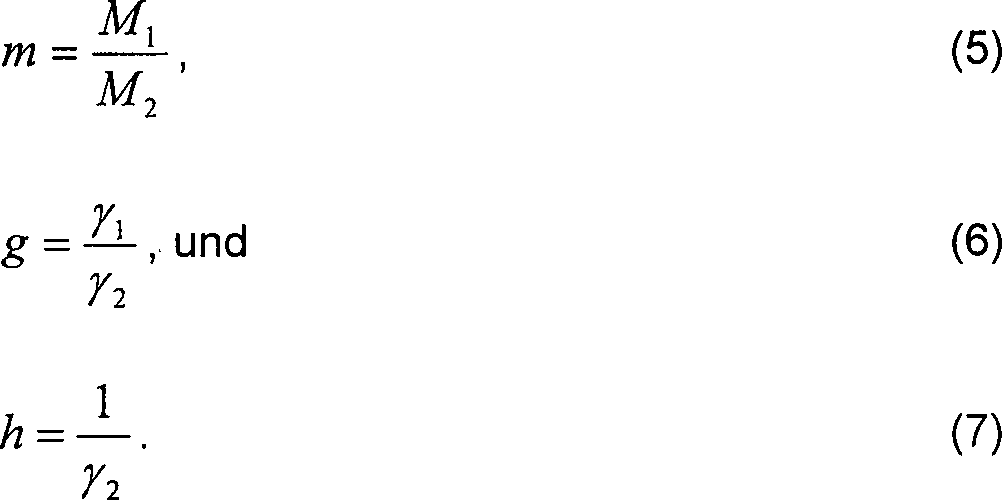
Wenn
x der Molenbruch des Vorläufergases
im Trägergas
ist, folgt ![]()
![]()
![]()
![]()
![]()
![]()
Durch
Einsetzen der Werte (5) bis (7) in die Gleichungen (1) bis (4),
erhalten wir 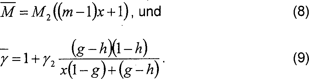
Die
Gleichungen (8) und (9) führen
in Verbindung mit Gleichung (1) zu 
![]()
![]()
Da
die gemessenen Resonanzfrequenzen in einem akustischen Resonator
direkt proportional zur Schallgeschwindigkeit sind, können wir
das folgende Verhältnis
definieren ![]()
![]()
![]()
![]()
Ein
Vereinfachung der Gleichung (13) führt zu folgender quadratischen
Gleichung
Die
Lösungen
der Gleichung (14) haben die Form ![]()
![]()
Akzeptable
Lösungen
müssen
innerhalb realistischer Grenzen bleiben, beispielsweise 0 ≤ x1,2 ≤ 1.
Bei der überwiegenden
Zahl binäre
Gassysteme gibt es nur eine Lösung
für x,
was darauf hin weist, dass eine monotone Relation zwischen dem Molenbruch
des Trägergases
und der Schallgeschwindigkeit besteht.
Bei dieser Erfindung sind die in Gleichung (13) enthaltenen Variablen m, g und i (h ?!) für das zu analysierende binäre Gas bekannt. Sobald λ bestimmt worden ist, kann x1,2 berechnet werden. Da f2 bekannt ist, können wir aus Gleichung (12) den Wert für x errechnen sobald wir f bestimmt haben. Die folgende Diskussion zur akustischen Resonanz ist hilfreich für das Verständnis der vorliegende Erfindung.In this invention, the variables m, g and i (h?!) Contained in equation (13) are known for the binary gas to be analyzed. Once λ has been determined, x1.2 can be calculated. Since f 2 is known, we can calculate the value of x from equation (12) as soon as we have determined f. The following discussion on acoustic resonance is helpful in understanding the present invention.
Ein
Gasresonator kann als ein durch eine harmonische Schwingung angeregter
gedämpfter
Resonator betrachtet werden, also ![]()

![]()
![]()
![]()
Die
Phasenverzögerung
ergibt sich aus ![]()
![]()
Somit
ist das betrachtete System durch die Schwingungsamplitude x0 und die Phasenverzögerung φ vollständig beschrieben. Die Schwingungsamplitude
x0 ist am größten, wenn f gleich f0. Eine Analyse der Gleichung (23) zeigt,
dass
φ =
0 für f<<f0,
φ = -π/2 für f=f0, and
φ = -π für f>>f0.Thus, the system under consideration is fully described by the oscillation amplitude x 0 and the phase delay φ. The oscillation amplitude x 0 is greatest when f equals f 0 . An analysis of equation (23) shows that
φ = 0 for f << f 0 ,
φ = -π / 2 for f = f 0 , and
φ = -π for f >> f 0 .
Da Q-1 das Verhältnis der durch Dämpfung verursachten Energieverlustrate zu der im Resonator insgesamt gespeicherten Energie darstellt, bestimmen f0 und Q die Mechanik des Resonatorsystems in hinreichender Weise.Since Q -1 represents the ratio of the energy loss rate caused by attenuation to the total energy stored in the resonator, f 0 and Q adequately determine the mechanics of the resonator system.
Die
Bestimmung der Resonanzfrequenz f0 aus Amplitudenmessungen
erfolgt mittels der folgenden aus Gleichung (20) entwickelten Gleichung ![]()
![]()
Die
Division von y(f) durch y(f0) ergibt ![]()
![]()
In
der Nähe
der Resonanz gilt f2 – f2 ≈ 2f0(f0 – f). Da
f0 bis hierher noch nicht bestimmt ist,
beziehen wir die Frequenzen auf eine in der Nähe der Resonanzfrequenz f0 liegende Referenzfrequenz fR,
wobei
Wenn
wir jetzt y(f)/y(f0) unter Bezug auf die
inkrementelle Frequenz Δ umformen,
erhalten wir ![]()
![]()
Im
Hinblick auf die zur Bestimmung der bestangepassten Werte für b0, b1, and b2 erforderliche parabolische Regression für y(Δ), werden
um fR herum mehrere Messungen vorgenommen,
was weiter unten näher erklärt wird.
Die Gleichungen (29) bis (31) ergeben dann 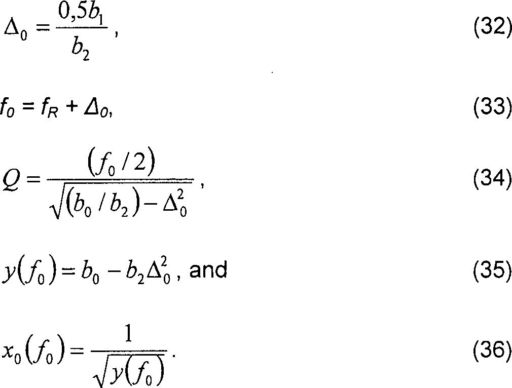
Um
die Resonanzfrequenz f0 aus einer Phasenmessung
bestimmen zu können,
schreiben wir Gleichung (23) folgendermaßen um 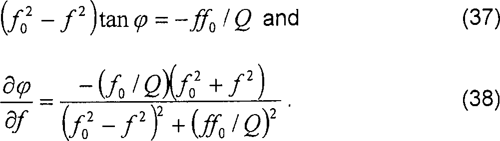
Wie
oben erwähnt
gilt in der Nähe
der Resonanz f2 – f2 ≈ 2f0(f0 – f). Deshalb
gilt 
Wiederum,
da f0 bis hierher noch nicht bestimmt ist,
beziehen wir die Frequenzen auf eine in der Nähe der Resonanzfrequenz f0 liegende Referenzfrequenz fR,
wobei
Somit
gilt ![]()
![]()
![]()
![]()
Vor
Ausführung
der parabolische Regression werden, zur Bestimmung der bestangepassten
Werte für die
Regressionskoeffizienten, um fR herum mehrere
Messungen vorgenommen. Gleichungen (43) bis (45) ergeben sodann 
Die
oben erwähnte
parabolische Regressionsmethode wird wie folgt erklärt. Ausgehend
von einem Modell der Form
Die
bestangepassten Parameter erhält
man durch Invertierung dieser Regressionsmatrix. Obwohl diese Matrix
für jede
beliebig Zahl von Messpunkten invertiert werden kann, ergibt sich
eine Vereinfachung, wenn man symmetrisch um den Referenz-Nullpunkt
verteilte Messpunkte in gleichen Abständen voneinander wählt. Dann
werden die Hälfte
der Matrizenelemente auf Null reduziert. Beispielsweise, 11 um den
Referenzpunkt herum verteilte Messpunkte im Abstand von jeweils
1 Hz ergeben n = 11, ∑x
= 0, ∑x2 = 110, ∑x3 = 0, und ∑x4 =
1958. Mit diesen Werten lassen sich die Werte für b aus der folgenden invertierten
Matrix-Gleichung berechnen 
Sobald
die b-Parameter bekannt sind, kann die Resonanzfrequenz f0 wie oben beschrieben aus Amplitudenmessungen
oder Phasenmessungen bestimmt werden. Bei gleichen Abständen der
Messpunkte, aber nicht notwendigerweise 1 Hz, müssen die b-Parameter wie folgt auf die Inkremente
s skaliert werden:
b0 → b0,
b1 → b1/s, und
b2 → b2/s2.Once the b-parameters are known, the resonant frequency f 0 can be determined from amplitude measurements or phase measurements as described above. For equal distances of the measuring points, but not necessarily 1 Hz, the b-parameters must be scaled to the increments s as follows:
b 0 → b 0 ,
b 1 → b 1 / s, and
b 2 → b 2 / s 2 .
Bezug
nehmend auf die
Bezug
nehmend auf die
Die
Schallsendemikrofonkapsel
Ein
Antriebssignal
Bezug
nehmend auf die
Das
Schallempfangsmikrofon
Bezug
nehmend auf
Ein
Gaszuführungsrohr
Bezug
nehmend auf
Eine
alternative Messmethode, die als Phasen-Sperr-Methode bezeichnet
werden kann, wird kurz beschrieben. In einem bestimmten gasförmigen Medium
ist die Phasenverzögerung
zwischen Schallempfangs- und Schallsendekopf bei der Resonanzfrequenz
f0 konstant, solange die Zusammensetzung
des Gases nicht schwankt. Jede auf eine Veränderung der Gaszusammensetzung
zurückzuführende Änderung
der Phasenverzögerung
zwingt den digitalen Sinuswellengenerator, die Frequenz des Treibersignals
Die
Kalibrierung erfolgt bei den zu erwartenden Betriebswerten der Temperatur,
des Drucks und der Flussrate, indem reines Trägergas durch die Akustikzelle
Bezug
nehmend auf
Bezug
nehmend auf
Das
Signal e(t) kann durch die Formel e(t) = RV0( ∂c / ∂t)C
ausgedrückt
werden, mit ∂c / ∂t, der zeitlichen Ableitung der Kapazität zwischen
der Abschlussmembran
Im
Folgenden wird die Auswertung des Betriebs der vorliegenden Erfindung
beschrieben. Die Akustikzelle
Bezug
nehmend auf
Sodann
sind die Resonanzfrequenzen der Akustikzelle im jeweiligen Gas bei
Flussraten von 5, 10 und 15 ml/min gemessen worden. Die Resultate
sind in
Bezug
nehmend auf
Bezug
nehmend auf
Die Differenz zwischen gemessenem Molenbruch und geschätztem idealen Molenbruch steigt mit wachsender Flussrate im Bubbler. Es wird vermutet, dass bei die Mitreiß-Effizienz mit zunehmender Flussrate des Wasserstoffs durch den TMI-Bubbler abnimmt. Deshalb führen konventionelle, auf der Mengen-Flussrate basierende Berechnungsmethoden wahrscheinlich zu einer Überschätzung des resultierenden Molenbruchs.The Difference between measured mole fraction and estimated ideal Molenbruch increases with increasing flow rate in the bubbler. It is believed that at the entrainment efficiency with increasing flow rate of hydrogen through the TMI bubbler decreases. Therefore lead conventional flow rate based calculation methods probably to overestimate the resulting mole fracture.
Bezug
nehmend auf
Claims (14)
Applications Claiming Priority (2)
| Application Number | Priority Date | Filing Date | Title |
|---|---|---|---|
| US1967596P | 1996-06-13 | 1996-06-13 | |
| US19675P | 1996-06-13 |
Publications (2)
| Publication Number | Publication Date |
|---|---|
| DE69737221D1 DE69737221D1 (en) | 2007-02-22 |
| DE69737221T2 true DE69737221T2 (en) | 2007-10-25 |
Family
ID=21794453
Family Applications (1)
| Application Number | Title | Priority Date | Filing Date |
|---|---|---|---|
| DE1997637221 Expired - Fee Related DE69737221T2 (en) | 1996-06-13 | 1997-06-12 | Acoustic sensor with resonator cell for continuous monitoring of gases |
Country Status (3)
| Country | Link |
|---|---|
| EP (1) | EP0813060B1 (en) |
| JP (1) | JP3615019B2 (en) |
| DE (1) | DE69737221T2 (en) |
Families Citing this family (8)
| Publication number | Priority date | Publication date | Assignee | Title |
|---|---|---|---|---|
| JP2003315318A (en) * | 2002-04-26 | 2003-11-06 | Japan Atom Energy Res Inst | Method and apparatus for measuring partial pressure ratio of mixed gas nondestructively in real-time based on measured resonance frequency of the mixed gas in container |
| EP1860433A1 (en) * | 2006-05-24 | 2007-11-28 | TF Instruments, Inc. | Ultrasonic resonator cell with uniform pressure on the ultrasonic transducers |
| DE102006045921B4 (en) | 2006-09-28 | 2022-07-14 | Robert Bosch Gmbh | Fuel cell with a device for the quantitative determination of gas components |
| GB201120887D0 (en) | 2011-12-06 | 2012-01-18 | The Technology Partnership Plc | Acoustic sensor |
| GB2569467B (en) | 2012-04-05 | 2019-10-30 | Fisher & Paykel Healthcare Ltd | Respiratory assistance apparatus |
| US11433210B2 (en) | 2014-05-27 | 2022-09-06 | Fisher & Paykel Healthcare Limited | Gases mixing and measuring for a medical device |
| US10983092B2 (en) | 2014-12-11 | 2021-04-20 | The Technology Partnership Plc | Acoustic sensor |
| GB2599020B (en) | 2015-12-02 | 2022-06-22 | Fisher & Paykel Healthcare Ltd | Flow path sensing for flow therapy apparatus |
Family Cites Families (3)
| Publication number | Priority date | Publication date | Assignee | Title |
|---|---|---|---|---|
| FR1469145A (en) * | 1965-12-28 | 1967-02-10 | Commissariat Energie Atomique | Sonic analyzer |
| GB2203247A (en) * | 1987-04-04 | 1988-10-12 | Schlumberger Electronics | Gas analyser |
| US5524477A (en) * | 1993-11-29 | 1996-06-11 | Leybold Inficon Inc. | Quantitative determination of air present in refrigerant sample by measurement of pressure coefficient of resonance frequency |
-
1997
- 1997-06-12 DE DE1997637221 patent/DE69737221T2/en not_active Expired - Fee Related
- 1997-06-12 EP EP19970109581 patent/EP0813060B1/en not_active Expired - Lifetime
- 1997-06-13 JP JP15705697A patent/JP3615019B2/en not_active Expired - Fee Related
Also Published As
| Publication number | Publication date |
|---|---|
| EP0813060A3 (en) | 1998-09-16 |
| EP0813060A2 (en) | 1997-12-17 |
| EP0813060B1 (en) | 2007-01-10 |
| JPH1073574A (en) | 1998-03-17 |
| JP3615019B2 (en) | 2005-01-26 |
| DE69737221D1 (en) | 2007-02-22 |
Similar Documents
| Publication | Publication Date | Title |
|---|---|---|
| DE19531360B4 (en) | Device and method for controlling the sensitivity of transducers | |
| EP2041529B1 (en) | Sytem for determining and/or monitoring a process quantity of a medium | |
| US5768937A (en) | Acoustic sensor for in-line continuous monitoring of gasses | |
| EP1208359B1 (en) | Methof of determining characteristic parameters of a mass flow rate measuring device during operation | |
| DE3822716C2 (en) | Device for monitoring changes in the ultrasonic properties of a fiber-reinforced plastic during a curing process | |
| DE69737221T2 (en) | Acoustic sensor with resonator cell for continuous monitoring of gases | |
| DD283560A5 (en) | METHOD AND DEVICE FOR THE UNIVASIVE ACOUSTIC CONTROL OF THE ELASTICITY OF SOFT BIOLOGICAL TISSUE | |
| DE69907913T2 (en) | CROSS MEASUREMENT OF ACOUSTIC SIGNALS OF A FLOW METER | |
| EP3084414A1 (en) | Device and method for determining the concentrations of components of a gas mixture | |
| EP1774269A1 (en) | Synchronous pressure and temperature determination | |
| DE10361464A1 (en) | Device for determining and / or monitoring the volume and / or mass flow rate of a measuring medium | |
| AT515552B1 (en) | Method and device for determining a density value | |
| EP1478949A1 (en) | Method and measuring device for locating enclosed objects | |
| EP1442276B1 (en) | Manometric sensor with separating membrane and temperature compensation | |
| EP1218703B1 (en) | Acoustic pressure calibrator | |
| EP3521774A1 (en) | Ultrasound flow meter and method for determining the flow speed | |
| EP1746344A2 (en) | Method for adjusting the acoustic properties of a combustion chamber | |
| DE202006021163U1 (en) | Device for determining the concentrations of components of a gas mixture | |
| EP0845661A1 (en) | Method and arrangement for measuring the flow velocity of a medium | |
| DE102016112679A1 (en) | Method and arrangement for analyzing gas properties | |
| DE3825422A1 (en) | Device for measuring the density of fluids by means of acoustic signals | |
| DE10131823A1 (en) | Field device for measuring acoustic impedance, especially for measuring the acoustic impedance of the vocal tract, has an acoustic excitation system and pressure and sound speed sensors | |
| DE19605923C2 (en) | Flow meter | |
| WO1997042509A1 (en) | Method of measuring the rate of flow of gaseous or liquid media using ultrasound, and measuring device suitable for carrying out said process | |
| EP0162237A1 (en) | Method and apparatus for the ultrasonic measurement of fluid-flow velocity |
Legal Events
| Date | Code | Title | Description |
|---|---|---|---|
| 8364 | No opposition during term of opposition | ||
| 8339 | Ceased/non-payment of the annual fee |