DE69729219T2 - HIGH MECHANICAL VOLTAGE MATERIALS FOR MAGNETIC FIELD-CONTROLLED ACTUATOR - Google Patents
HIGH MECHANICAL VOLTAGE MATERIALS FOR MAGNETIC FIELD-CONTROLLED ACTUATOR Download PDFInfo
- Publication number
- DE69729219T2 DE69729219T2 DE69729219T DE69729219T DE69729219T2 DE 69729219 T2 DE69729219 T2 DE 69729219T2 DE 69729219 T DE69729219 T DE 69729219T DE 69729219 T DE69729219 T DE 69729219T DE 69729219 T2 DE69729219 T2 DE 69729219T2
- Authority
- DE
- Germany
- Prior art keywords
- actuator
- field
- twin
- martensitic
- magnetic field
- Prior art date
- Legal status (The legal status is an assumption and is not a legal conclusion. Google has not performed a legal analysis and makes no representation as to the accuracy of the status listed.)
- Expired - Fee Related
Links
Classifications
-
- H—ELECTRICITY
- H10—SEMICONDUCTOR DEVICES; ELECTRIC SOLID-STATE DEVICES NOT OTHERWISE PROVIDED FOR
- H10N—ELECTRIC SOLID-STATE DEVICES NOT OTHERWISE PROVIDED FOR
- H10N35/00—Magnetostrictive devices
- H10N35/80—Constructional details
- H10N35/85—Magnetostrictive active materials
Abstract
Description
ALLGEMEINES ZUR ERFINDUNGGENERAL To the invention
Die vorliegende Erfindung bezieht sich auf Aktorenmaterialien und insbesondere bezieht sie sich auf Materialien, die eine Betätigungsreaktion auf eine von außen angelegte Stimulierung wie zum Beispiel einen angelegten Feldreiz zeigen können.The The present invention relates to actuator materials, and more particularly it refers to materials that cause an actuation reaction to one of Outside applied stimulation such as an applied field stimulus be able to show.
Die Fähigkeit, Aktorenmaterialien für die Erzeugung von Bewegung und Kraft als Reaktion auf einen angelegten Reiz wirksam einzusetzen, wird in hochentwickelten Einsatzgebieten im Förderbereich und im Bereich der Luft- und Raumfahrttechnik, bei hochmodernen Automatisierungs- und Herstellungsprozessen und in einer großen Palette weiterer Bereiche zunehmend bedeutsam. Von besonderem Interesse ist die Entwicklung von Aktorenmaterialien mit hohen Spannungen, erheblicher Krafterzeugung und kurzer Reaktionszeit beim Ansprechen auf eine Stimulierung von außen. Zu den allgemein beliebten Gruppen von Aktorenmaterialien gehören piezoelektrische, magnetostriktive Aktorenmaterialien und Werkstoffe mit Formgedächtnis; es wurde festgestellt, dass jede dieser drei Gruppen sowohl Vorteile in der Leistung als auch Einschränkungen bei ihren Fähigkeiten in der Betätigung besitzt.The Ability, Actuator materials for the generation of movement and force in response to an applied To use stimulus effectively, is used in advanced applications in the funding area and in the field of aerospace engineering, state-of-the-art Automation and manufacturing processes and in a wide range increasingly important. Of special interest is the development of actuator materials with high voltages, considerable power generation and short reaction time when responding on stimulation from the outside. Popularly popular groups of actuator materials include piezoelectric, magnetostrictive actor materials and shape memory materials; It was found that each of these three groups has both benefits in performance as well as limitations at their abilities in the operation has.
Im typischen Fall handelt es sich bei piezoelektrischen Werkstoffen um Keramikmaterialien, z. B. Blei-Zirkonat-Titanat, und sie zeichnen sich durch ihre Fähigkeit aus, sich im Ansprechen auf ein angelegtes elektrisches Feld bei der Demonstration des umgekehrten piezoelektrischen Effekts mechanisch zu verformen, d. h. sich auszudehnen und zusammenzuziehen. Piezoelektrische Betäti gungselemente aus Keramikmaterial, die herkömmlicherweise in Reihe in gestapelter Form verwendet werden, zeigen eine akzeptable Ausgangs-Energiedichte und außerdem eine sehr große Bandbreite, d. h. einen vergleichsweise schnellen Betätigungshub. Eine piezoelektrische Stapelstruktur ist jedoch im Allgemeinen nur auf einen vergleichsweise kleinen Hub beschränkt und kann im typischen Fall nur eine begrenzte Ausgangskraft erzeugen, was weitgehend auf die charakteristische Sprödigkeit der piezoelektrischen Werkstoffe zurückzuführen ist. Infolgedessen werden von einem Aktor, der ein piezoelektrisches Aktorenmaterial enthält, Hubmechanismen und Mechanismen zur Kraftverstärkung gefordert, doch kann auf vielen Einsatzgebieten die begrenzte piezoelektrische Betätigungskraft für die jeweilige Anwendung in der Praxis nicht ausreichend groß gemacht werden.in the typical case is piezoelectric materials to ceramic materials, eg. As lead zirconate titanate, and they draw through their ability out in response to an applied electric field at the demonstration of the reverse piezoelectric effect mechanically to deform, d. H. to expand and contract. piezoelectric Actuate supply elements made of ceramic material, conventionally Used in series in stacked form, show an acceptable Output energy density and as well a very big one Bandwidth, d. H. a comparatively fast actuation stroke. However, a piezoelectric stack structure is generally only limited to a relatively small stroke and can typically generate only a limited output, which is largely due to the characteristic brittleness is due to the piezoelectric materials. As a result, will from an actuator containing a piezoelectric actuator material, lifting mechanisms and mechanisms for power amplification However, in many applications, the limited piezoelectric operating force for the respective application in practice not made big enough become.
Magnetostriktive Aktorenmaterialien zeichnen sich im typischen Fall dadurch aus, dass sie in der Lage sind, eine Betätigungskraft und einen Betätigungshub zu erzeugen, die größer als bei den piezoelektrischen Materialien. Die Anlegung eines Magnetfelds an ein magnetostriktives Material veranlasst den Werkstoff zur Ausbildung von Spannungen, je stärker sich die Vektoren des Materials zur Bereichsmagnetisierung drehen, um sich auf die Richtung des angelegten Magnetfelds auszurichten. Die Zelleinheiten des Materials erfahren durch die Drehung bei der Magnetisierung eine elastische Verformung, doch verändert sich ihre Ausrichtung nicht.magnetostrictive Actuator materials are typically characterized by that they are capable of an operating force and a Betätigungshub to produce larger than in the piezoelectric materials. The application of a magnetic field to a magnetostrictive material causes the material for training of tensions, the stronger the vectors of the material turn to the domain magnetization to to align with the direction of the applied magnetic field. The Cell units of material undergo rotation by magnetization an elastic deformation, but their orientation does not change.
Es hat sich gezeigt, dass Legierungen aus seltenen Erden die stärksten magnetostriktiven elastischen Verformungen aufweisen, z. B. zeigt sich bei der Laves-Phase bei TbFe2 eine Magnetostriktion λ von etwa 1753 × 10–6 bei Zimmertemperatur in einem angelegten Feld von etwa 1,98 × 10¹⁰ Alm (25 kOe), und bei dem pseudo-binären Material nahe Null – Tb0,27Dy0,73Fe2 – das auf dem Markt als Terfenol-D® bekannt ist, zeigt sich eine einfache Achsen-Magnetostriktion λ111 von etwa 1600 × 10–6 in Felder von der Größenordnung von etwa 7,95 × 10⁸ A/m (1 kOe). Der Begriff „leichte Achse" wird in diesem Zusammenhang in dem Sinn verwendet, dass er sich auf die Kristallachse bezieht, entlang welcher ein Magnetisierungsvektor eines Bereichs lieber bei Fehlen eines angelegten Feldes liegt; die leichte Achse ist somit die Richtung einer einfachen Magnetisierung für einen Bereich.It has been found that alloys of rare earth have the strongest magnetostrictive elastic deformations, eg. For example, in the Laves phase at TbFe 2, a magnetostriction λ of about 1753 × 10 -6 at room temperature in an applied field of about 1.98 × 10 10 Alm (25 kOe) and close to the pseudo-binary material is evident Zero - Tb 0.27 Dy 0.73 Fe 2 - known in the marketplace as Terfenol- D® , shows a simple axis magnetostriction λ 111 of about 1600 × 10 -6 in fields of the order of about 7, 95 × 10 8 A / m (1 kOe). The term "easy axis" is used in this context to refer to the crystal axis along which a magnetization vector of a region lies rather in the absence of an applied field, thus the easy axis is the direction of simple magnetization for a region ,
Die Belastungen bzw. Spannungen und die entsprechenden Kräfte, die von intermetallischen Stoffen auf Fe-Dy-Tb-Basis wie zum Beispiel Terfenol-D® entwickelt werden, können beträchtlich größer als die Spannungen und Kräfte bei piezoelektrischen Werkstoffen sein, und die Werte der Energiedichte bei solchen intermetallischen Werkstoffen können in einer Größenordnung liegen, die größer als bei herkömmlichen Betätigungs- bzw. Aktorensystemen ist, zum Beispiel bei hydraulischen Anlagen. Die elastische Verformung zeigt bei unbelastetem Terfenol-D® eine Feldempfindlichkeit von etwa 0,6 × 10⁻⁶ pro 79,5775 A/m (Oe) unter dem Einfluss eines Magnetfelds von etwa 7,95 × 10⁸ A/m (1.000 Oe) und bei vorgespannten Materialauslegungen kann eine sogar noch höhere Spannungsempfindlichkeit gegenüber einem angelegten Feld ermöglicht werden.The stresses and strains and forces developed by Fe-Dy-Tb-based intermetallics, such as Terfenol- D® , can be significantly greater than the stresses and forces of piezoelectric materials and the values of energy density in such intermetallic materials may be of a magnitude that is greater than in conventional actuation or actuator systems, for example in hydraulic systems. The elastic deformation is in the unstressed Terfenol-D ®, a field sensitivity of about 0.6 x 10 -6 per 79.5775 A / m (Oe) under the influence of a magnetic field of about 7.95 x 10 8 A / m (1,000 Oe ) and biased material designs may allow even higher voltage sensitivity to an applied field.
Während magnetostriktive Aktorenelemente tatsächlich ein Ansprechverhalten mit Betätigung mit hoher Frequenz zeigen, werden sie grundlegend durch ihre elektrische Leitfähigkeit eingeschränkt, was auf Grund von Wirbelstrombildungen in dem Werkstoff als Reaktion auf ein sich veränderndes angelegtes Magnetfeld den Betrieb bei sehr hohen Betätigungsfrequenzen ausschließt, sofern nicht mindestens eine der Werkstoffabmessungen der Elemente senkrecht zu dem Feld klein ist. Eine zusätzliche einschränkende Beschränkung besteht bei magnetostriktiven Werkstoffen darin, dass sie sich im typischen Fall durch einen Betätigungshubauszeichnen, der wie bei den piezoelektrischen Betätigungselementen hinsichtlich seines Umfangs eingeschränkt ist, im vorliegenden Fall aufgrund der Bereichsdehnung, die dem Betätigungsmechanismus innewohnt.While magnetostrictive actuator elements actually have a response with ho Because of their eddy currents in the material in response to a changing applied magnetic field, they preclude operation at very high operating frequencies unless at least one of the material dimensions of the elements normal to the field is small is. An additional limiting constraint for magnetostrictive materials is that they are typically characterized by an actuation stroke that is limited in circumference, as in the case of the piezoelectric actuators, in the present case due to the range strain inherent in the actuation mechanism.
Die Gruppe von Aktorenmaterialien, die als Legierungen mit Formgedächtnis bekannt ist, zeichnet sich dadurch aus, dass eine Legierung mit Formgedächtnis bei plastischer Verformung bei einer bestimmten Temperatur oder einer bestimmten Belastungsbedingung in einer Phase, die als martensitische Phase bekannt ist, ihre ursprüngliche Form wieder einnehmen kann, wenn sie einer für die Legierung spezifischen Temperatur oder Spannungsbedingung für den Phasen übergang vom martensitischen in den austenitischen Zustand ausgesetzt wird, welche das Material in eine entsprechende austenitische Phase zurückführt. Diesem Effekt liegt die Zurückführung von Zwillingsvarianten der martensitischen Phase des Materials in ihre Form im austenitischen Zustand zugrunde. Solche Materialien sind in der Lage, eine große, durch Spannung herbeigeführte martensitische Verformung rückgängig zu machen, wenn sie zurück in die austenitische Phase transformiert werden, und damit können sie einen Wirkungsmechanismus mit großem Betätigungshub ermöglichen. Des Weiteren gilt die wieder aufbaubare Belastung, die eine Legierung mit Formgedächtnis aufnehmen kann, im Allgemeinen als die stärkste elastische Verformung, die bei jedem Aktorenmaterial erzielt werden kann, und diese kann sogar etwa 20% betragen, beispielsweise bei einer Legierung aus Kupfer, Aluminium und Nickel.The Group of actor materials known as shape memory alloys is characterized by the fact that a shape memory alloy at plastic deformation at a certain temperature or a certain load condition in a phase called martensitic Phase is known, its original Form can resume if they are specific to the alloy Temperature or voltage condition for the phase transition from the martensitic to the austenitic state, which returns the material to a corresponding austenitic phase. this Effect is the reduction of Twin variants of the martensitic phase of the material in their Form in the austenitic state. Such materials are able to make a big, tension-induced martensitic Undo deformation make when they go back into the austenitic phase, and they can allow a mechanism of action with a large actuation stroke. Furthermore, the recoverable load, which is an alloy with shape memory generally considered the strongest elastic deformation, which can be achieved with any actuator material, and this can even about 20%, for example in the case of an alloy Copper, aluminum and nickel.
Der große Hub, der im Allgemeinen charakteristisch für Legierungen mit Formgedächtnis ist, wird durch die typischerweise sehr lange Zeit in der Reaktion der Werkstoffe in der Betätigung wieder aufgehoben, wenn der Übergang aus dem martensitischen in den austenitischen Zustand thermisch gesteuert wird. Infolgedessen kann die Betätigung unter der Wirkung des Formgedächtnisses keine Einsatzbereiche abdecken, die auch nur mäßig hohe Betätigungsfrequenzen voraussetzen. Außerdem zeichnet sich die Transformation beim Formgedächtnis im Allgemeinen durch einen schlechten Wirkungsmechanismus bei der Energieumwandlung aus; ein großer Teil der Wärme, die dem Material zugeführt wird, um den Übergang aus dem martensitischen in den austenitischen Zustand anzusteuern, geht unkontrollierbar in die Umgebung verloren. Die thermische Steuerung des Formgedächtnis-Effekts schränkt auch den zulässigen Temperaturbereich bei den Betriebstemperaturen bei einer Anwendung ein, für die eine Legierung mit Formgedächtnis eingesetzt werden soll.Of the size Hub, which is generally characteristic of shape memory alloys, is characterized by the typically very long time in the reaction of the Materials in the actuation lifted again when the transition from the martensitic to the austenitic state thermally is controlled. As a result, the operation may be under the effect of shape memory do not cover any areas of application that also only moderately high operating frequencies provide. Furthermore the transformation of shape memory generally prevails a bad mechanism of action in energy conversion; a large Part of the heat, which fed to the material will be to the transition from the martensitic to the austenitic state, is lost uncontrollably in the environment. The thermal control the shape memory effect restricts also the permissible Temperature range at the operating temperatures in one application one, for the one with shape memory should be used.
In den Fachaufsätzen „Magnetisch gesteuerte Legierungen mit Formgedächtnis: eine neue Klasse von Aktorenmaterialien" im „Journal of Materials Engineering and Performance", Jahrgang 5, Nr. 3, 1. Juni 1996, Seiten 405–409, XP000593943, und „Aktorenmaterialien für großen Hub und mit hoher Festigkeit für adaptive Strukturen", der als Beitrag bei der Dritten Internationalen Konferenz über Intelligente Werkstoffe, 3.–5. Juni 1996, Lyon, vorgetragen wurde; Conference Proceedings, Seiten 505–510, 1996; SPIE, USA, XP002047296, hat K. Ullakko nachgewiesen, dass sich ein magnetisch gesteuerter Effekt des Formgedächtnisses in ausgewählten ferromagnetischen Werkstoffen nachweisen lässt, wie zum Beispiel in Ni2MnGa, in denen die martensitischen Grenzflächen gleitfähig sind und die anisotrope Energie des Materials ausreichend hoch ist.In the articles "Magnetically controlled alloys with shape memory: a new class of Aktorenmaterialien" in the "Journal of Materials Engineering and Performance", Vol. 5, No. 3, June 1, 1996, pages 405-409, XP000593943, and "Aktorenmaterialien for large Hub and High Strength for Adaptive Structures ", which was presented as a contribution to the Third International Conference on Advanced Materials, June 3-5, 1996, Lyon; Conference Proceedings, pp. 505-510, 1996; SPIE, USA, XP002047296 , K. Ullakko has demonstrated that a magnetically controlled shape memory effect can be detected in selected ferromagnetic materials, such as Ni 2 MnGa, where the martensitic interfaces are slippery and the anisotropic energy of the material is sufficiently high.
Bei vielen Einsatzbereichen von Aktoren wird im Idealfall eine Kombination aus dem großen Betätigungshub, den die Legierungen mit Formgedächtnis bieten, mit der kurzen Reaktionszeit in der Betätigungsaktion bei magnetostriktiven und piezoelektrischen Materialien bevorzugt. Gleichzeitig werden auch vorzugsweise die thermischen Einschränkungen bei piezoelektrischen und magnetostriktiven Werkstoffen und Werkstoffen mit Formgedächtnis beseitigt. Ein einziges Aktorenmaterial, das alle diese Qualitäten in sich vereinigt, war bisher unter praktischen Betriebsbedingungen nicht realisierbar.at Many applications of actuators will ideally be a combination from the big one operating stroke, the alloys with shape memory offer, with the short reaction time in the action of action in magnetostrictive and piezoelectric materials are preferred. At the same time also preferably the thermal limitations of piezoelectric and magnetostrictive and shape memory materials. A single actor material that has all these qualities in it united, was not under practical operating conditions so far realizable.
KURZBESCHREIBUNG DER ERFINDUNGSUMMARY THE INVENTION
Die vorliegende Erfindung überwindet die Einschränkungen bei herkömmlichen Aktorenmaterialien und schafft so ein magnetisch gesteuertes Aktorenmaterial, das einen großen Hub in der Aktorenbetätigung erbringt, der eine kurze Reaktionszeit in der Aktion und einen Betrieb mit entsprechend hoher Arbeitsfrequenz mit sich bringt und eine effiziente Umwandlung der Betätigungsenergie unter günstigen Betriebstemperaturen ermöglicht.The overcomes the present invention the restrictions at conventional Actuator materials and thus creates a magnetically controlled actuator material, that's a big one Stroke in the actuation of the actuator, which has a short reaction time in the action and operation with correspondingly high working frequency and an efficient Transformation of the actuation energy under cheap Operating temperatures possible.
Ein Betätigungselement gemäß der vorliegenden Erfindung wird in Anspruch 1 beansprucht.One actuator according to the present The invention is claimed in claim 1.
Gemäß einem Aspekt der Erfindung sieht diese ein Aktorenelement vor, das ein Aktorenmaterial aufweist, welches über einer charakteristischen Phasenübergangs-Temperatur, die höher ist als etwa –10°C, eine austenitische Kristallstruktur besitzt und unter der Phasenübergangs-Temperatur eine martensitische Zwillings-Kristallstruktur aufweist. Bei einem Ausführungsbeispiel handelt es sich bei dem Aktorenmaterial um eine Legierungszusammensetzung, die als Ni65–x–yMn20+xGa15+y definiert ist, wobei x zwischen 3 Atom-% und 15 Atom-% liegt und y zwischen 3 Atom-% und 12 Atom-Prozent liegt. Gemäß einem Aspekt der Erfindung zeichnet sich dabei das Aktorenmaterial durch eine magnetisch-kristalline anisotrope Energie aus, die ausreicht, um eine Bewegung von Zwillingsgrenzen der martensitischen Zwillings-Kristallstruktur im Ansprechen auf das Anlegen eines Magnetfeldes an die martensitische Zwillings-Kristallstruktur zu ermöglichen. Dies macht es dem Material möglich, im Ansprechen auf das Magnetfeld einen Betätigungshub zu erzeugen.According to one aspect of the invention, it provides an actuator element having an actuator material which has an austenitic crystal structure above a characteristic phase transition temperature higher than about -10 ° C, and has a martensitic twinned crystal structure at the phase transition temperature , In one embodiment, the actuator material is an alloy composition defined as Ni 65-x-y Mn 20 + x Ga 15 + y , where x is between 3 at% and 15 at% and y is between 3 at -% and 12 atomic percent lies. In one aspect of the invention, the actor material is characterized by a magneto-crystalline anisotropic energy sufficient to permit movement of twin boundaries of the martensitic twinned crystal structure in response to the application of a magnetic field to the martensitic twinned crystal structure. This makes it possible for the material to generate an actuating stroke in response to the magnetic field.
Auf der Grundlage dieses Wirkungsmechanismus überwinden die erfindungsgemäß vorgesehenen Aktorenmaterialien die Einschränkungen beim Wärmeverhalten, im Hubverhalten und im Frequenzverhalten, die typischerweise mit Aktorenmaterialien verknüpft sind, und ermöglichen eine Klasse von Aktoren mit großem Hub und hoher Geschwindigkeit, welche bei günstigen Einsatztemperaturen verwendet werden können.On the basis of this mechanism of action overcome the actor materials provided according to the invention the restrictions in thermal behavior, in the stroke behavior and in the frequency response, typically with Actuator materials linked are, and allow a class of actuators with great Stroke and high speed, which at low operating temperatures can be used.
Bei Ausführungsbeispielen, die erfindungsgemäß vorgesehen sind, handelt es sich bei dem Aktorenmaterial um eine Legierungszusammensetzung, die als Ni65–x–yMn20+xGa15+y definiert ist, wobei x zwischen 6 Atom-% und 10 Atom-% liegt und y zwischen 5 Atom-% und 9 Atom-Prozent liegt, oder bei dem x zwischen 12 Atom-% und 15 Atom-% und y zwischen 3 Atom-% und 6 Atom-% liegt, oder bei dem x zwischen 10 Atom-% und 14 Atom-% und y zwischen 3 Atom-% und 6 Atom-% liegt, oder bei dem x zwischen 7 Atom-% und 11 Atom-% und y zwischen 3 Atom-% und 7 Atom-% liegt.In embodiments provided according to the invention, the actuator material is an alloy composition defined as Ni 65-x-y Mn 20 + x Ga 15 + y , where x is between 6 at% and 10 at% and y is between 5 at.% and 9 at.%, or where x is between 12 at.% and 15 at.% and y is between 3 at.% and 6 at.%, or at x between 10 at. % and 14 at% and y is between 3 at% and 6 at%, or where x is between 7 at% and 11 at% and y between 3 at% and 7 at%.
Bei anderen Ausführungsbeispielen, die gemäß der Erfindung vorgesehen sind, handelt es sich bei dem Aktorenmaterial um eine polykristalline Legierungszusammensetzung, die als (NiaFebCoc)65–x–y(MndFeeCof)20+x(GagSihAl)15+y definiert ist, wobei x zwischen 3 Atom-% und 15 Atom-% liegt und y zwischen 3 Atom-% und 12 Atom-% liegt, und wobei a + b + c = 1 ist, wobei die Beziehungen d + e + f = 1 und g + h + i = 1 gelten. Bei bevorzugten Ausführungsbeispielen liegt b zwischen Null und 0,6, liegt c zwischen Null und 0,6, und sind e, f, h und i jeweils Null, oder sind b und c jeweils Null, liegt e zwischen etwa Null und etwa 0,6, liegt f zwischen Null und 0,6 und betragen h und i jeweils Null, oder sind b, c, e und f jeweils Null, liegt h zwischen Null und 0,5 und liegt i zwischen Null und 0,5.In other embodiments provided according to the invention, the actuator material is a polycrystalline alloy composition described as (Ni a Fe b Co c ) 65 -x-y (Mn d Fe e Co f ) 20 + x (Ga g Si h Al) 15 + y , where x is between 3 atomic% and 15 atomic% and y is between 3 atomic% and 12 atomic%, and where a + b + c = 1, where the relations d + e + f = 1 and g + h + i = 1 apply. In preferred embodiments, b is between zero and 0.6, c is between zero and 0.6, and are e, f, h, and i each zero, or are b and c each zero, is e between about zero and about 0, 6, f is between zero and 0.6 and h and i are each zero, or are b, c, e and f each zero, h is between zero and 0.5 and i is between zero and 0.5.
Bei anderen Ausführungsbeispielen handelt es sich bei dem Aktorenmaterial um eine Legierungszusammensetzung, die als CoaMnb(CrmPtnPdoAupNbqNir)c definiert ist, bei welcher a + b + c = 100 ist und m + n + o + p + q + r = 1 ist. Bei einem anderen Ausführungsbeispiel handelt es sich bei dem Aktorenmaterial um eine Legierungszusammensetzung, bei welcher a + b = 100 ist und a dabei zwischen 60 und 90 liegt und b einen Wert zwischen 10 und 40 aufweist.In other embodiments, the actuator material is an alloy composition defined as Co a Mn b (Cr m Pt n Pd o Au p Nb q Ni r ) c where a + b + c = 100 and m + n + o + p + q + r = 1. In another embodiment, the actuator material is an alloy composition in which a + b = 100 and a is between 60 and 90 and b has a value between 10 and 40.
Entsprechend einem weiteren Aspekt der Erfindung zeichnet sich das Aktorenmaterial durch eine Form mit einer langen Dimension aus, wobei das Aktorenmaterial so konfiguriert ist, dass es die Anlegung eines statischen magnetischen Vorspannfelds über eine Materialdimension, die nicht die lange Abmessung ist, und die Anlegung eines veränderlichen magnetischen Betätigungsfelds über die fange Dimension des Materials aufnehmen kann. Dadurch wird die Erzeugung eines Betätigungshubs entlang der langen Abmessung des Materials möglich. Bei bevorzugten Ausführungsbeispielen zeichnet sich das Aktorenmaterial durch einen Zustand der Vorbetätigung aus, bei welchem ein wesentlicher Teil der martensitischen Zwillingsgrenzen zu dem statischen magnetischen Vorspannfeld ausgerichtet ist. Vorzugsweise ist das Aktorenmaterial dabei so aufgebaut, dass es die Anlegung eines magnetischen Betätigungsfeldes in einer Ausrichtung aufnehmen kann, die mit einer ausgewählten martensitischen Ausrichtung der Zwillingsgrenzen des Materials zusammenfällt. Das Aktorenmaterial besitzt dabei vorzugsweise eine martensitische Zwillings-Kristallstruktur, die sich durch eine Anzahl t von ausgeprägten Zwillingsvarianten auszeichnet, die unter 5 und vorzugsweise unter 3 liegt.Corresponding In another aspect of the invention, the actuator material is characterized through a shape with a long dimension, the actor material is configured so that it is the application of a static magnetic Header field over a material dimension that is not the long dimension, and the Application of a variable magnetic field of activity over the capture the dimension of the material. This will produce an actuating stroke possible along the long dimension of the material. In preferred embodiments the actuator material is characterized by a state of pre-actuation, in which a substantial portion of the martensitic twin borders is aligned with the static magnetic bias field. Preferably the actuator material is constructed so that it is the application a magnetic field of activity can record in an alignment with a selected martensitic Alignment of the twin boundaries of the material coincides. The actor material preferably has a martensitic twin crystal structure, which is characterized by a number t of pronounced twin variants, which is less than 5 and preferably less than 3.
Die erfindungsgemäßen magnetisch gesteuerten Aktorenmaterialien eignen sich sehr gut für eine breite Palette von Einsatzbereichen für Aktoren, darunter die Robotik, die Fertigung und die Automatisierung, die Fördertechnik, die Luft- und Raumfahrt, die Biotechnologie, die mikro-elektromechanischen Systeme, intelligente Detektoren- und Messwandler-Systeme und sind ganz allgemein bei Einsatzgebieten überlegen, bei denen sich die Überlegungen auf Rauschen, Schwingungen, Hub, Geschwindigkeit, Temperatur und Leistungsfähigkeit beziehen. Weitere Merkmale und Vorteile der erfindungsgemäßen Werkstoffe ergeben sich aus der nachstehenden ausführlichen Beschreibung und den beiliegenden Zeichnungen sowie aus den Ansprüchen.The magnetic according to the invention controlled actuator materials are very suitable for a broad Range of uses for Actuators, including robotics, manufacturing and automation, the conveyor technology, aerospace, biotechnology, microelectromechanical Systems, intelligent detector and transducer systems and are quite generally superior in applications where the considerations on noise, vibration, stroke, speed, temperature and capacity Respectively. Further features and advantages of the materials according to the invention result from the detailed description below and the accompanying drawings and from the claims.
KURZBESCHREIBUNG DER ZEICHNUNGENSUMMARY THE DRAWINGS
BESCHREIBUNG DER ERFINDUNGDESCRIPTION THE INVENTION
Gemäß der Darstellung
in
Gemäß der Darstellung
in
Aufweist,
die ursprünglich
bezüglich
des angelegten Magnetfeldes günstig
war, dreht sich dabei nicht. Infolgedessen zeigt sich, dass sich,
sobald sich die zweite Zelleneinheit
Es
wird nun auf
Im makroskopischen Maßstab führt die Zunahme der Zwillingsvariante zu einer Formveränderung des Materials, was zu einem Betätigungshub führt. Ein Rückstell-Betätigungshub, der einer Wiederherstellung der ursprünglichen Form des Materials und auch einer ursprünglichen Ausrichtung der Zwillingsvariante entspricht, erhält man dann durch Entfernen des angelegten Magnetfeldes unter erneuter Ausrichtung des angelegten Magnetfeldes in eine andere Richtung oder durch andere geeignete Maßnahmen. Diese Betätigung in zwei Richtungen stützt sich nicht auf eine Temperaturveränderung als Stimulans für die Betätigung und wird somit nicht durch die im typischen Fall langsame thermische Reaktion von Aktorenmaterialien wie beispielsweise Legierungen mit Formgedächtnis.in the macroscopic scale leads the Increase of the twin variant to a change in the shape of the material, what to an actuating stroke leads. A reset actuation stroke, a restoration of the original form of the material and also an original one Alignment of the twin variant corresponds, you get then by removing the applied magnetic field with reorientation of the applied magnetic field in a different direction or by others appropriate measures. This operation supports in two directions does not respond to a change in temperature as a stimulant for the operation and thus not by the typically slow thermal reaction of actor materials such as shape memory alloys.
Die magnetisch gesteuerte Bewegung an der Zwillingsgrenze wird in Werkstoffen gemäß der Erfindung möglich gemacht, bei denen festgestellt wurde, dass sie eine magnetisch-kristalline Anisotropie-Energie besitzen, die vergleichbar der Energie – oder größer als diese – ist, die für eine Bewegung der Zwillingsgrenze in diesem Werkstoff benötigt wird. Die magnetisch-kristalline Anisotropie-Energie eines Materials ist die Energie, die benötigt wird, um die Magnetisierung der Zwillingsvarianten von der Achse weg zu drehen, welche der leichten kristallographischen Magnetisierung entspricht.The magnetically controlled movement at the twin boundary is in materials according to the invention possible made, which was found to be a magnetic-crystalline Have anisotropy energy comparable to the energy - or greater than this is, the for a movement of the twin boundary is needed in this material. The magnetic-crystalline anisotropy energy of a material is the energy that needs becomes the magnetization of the twin variants of the axis to turn away, which of light crystallographic magnetization equivalent.
Bei der vorstehenden Beschreibung wurde davon ausgegangen, dass alle Magnetisierungsvektoren entlang ihrer leichten Achsen ausgerichtet sind, wenn kein angelegtes Magnetfeld vorhanden ist. Wenn ein externes Magnetfeld angelegt wird, neigen die Magnetisierungsvektoren der Zelleneinheiten dazu, sich von ihrer Orientierung zur leichten Magnetisierung weg zur Ausrichtung des Magnetfelds hin zu drehen. Wenn aber das Material von einer Anisotropie-Energie charakterisiert wird, die der Energie vergleichbar oder größer als diese ist, die für die Bewegung der Zwillingsgrenze benötigt wird, d. h. wenn die Anisotropie-Energie des Materials ausreicht, um die Bewegung der Zwillingsgrenze aufzunehmen und zu unterstützen, dann veranlasst die Drehung der Magnetisierungsvektoren auch die entsprechenden Zelleinheiten zu einer Drehung aus ihrer ursprünglichen Ausrichtung als Zwillingsvariante in die Ausrichtung einer anderen Zwillingsvariante. Diese Drehung einer Zelleinheit wird in der Weise angesteuert, dass die neu orientierten Magnetisierungsvektoren wieder in die Richtung der leichten Magnetisierung in den gedrehten Zelleneinheiten verlaufen, was einem günstigen Energiezustand entspricht. Die hohe Anisotropie-Energie legt dadurch fest, dass die Zwillingsgrenzen sich bewegen, um die leichte Achse der Ausrichtung der Magnetisierungsvektoren aufrechtzuerhalten. Mit anderen Worten sind diejenigen Zwillingsvarianten, für welche sich die Magnetisierung in einer Hochenergie-Ausrichtung relativ zum angelegten Magnetfeld befindet, energetisch so disponiert sind, dass sie sich umorientieren und damit diese Zwillinge zum Schrumpfen bringen, zu gunsten der Zwillingsvarianten, für welche sich die Magnetisierung relativ zum angelegten Magnetfeld in einer Ausrichtung mit niedriger Energie befindet.at The above description assumes that all Magnetization vectors aligned along their easy axes are when there is no applied magnetic field. If an external Magnetic field is applied, the magnetization vectors of the Cell units to move from their orientation to easy magnetization to turn away to align the magnetic field. But if the material characterized by anisotropic energy, that of energy comparable or greater than this is who for the movement of the twin boundary is needed, d. H. if the anisotropy energy of the material is sufficient to accommodate the movement of the twin border and to support, then the rotation of the magnetization vectors also causes the corresponding cell units to a rotation from their original Alignment as a twin variant in the alignment of another Twin variant. This rotation of a cell unit becomes that way controlled that the newly oriented magnetization vectors again in the direction of easy magnetization in the rotated cell units run, which is a cheap Energy state corresponds. The high anisotropy energy lays thereby realize that the twin boundaries are moving around the easy axis to maintain the orientation of the magnetization vectors. In other words, those are twin variants, for which the magnetization in a high energy orientation relative to the applied magnetic field, are energetically so arranged, that they are reorienting themselves and thus making these twins shrink bring in favor of the twin variants, for which the magnetization relative to the applied magnetic field in a lower orientation Energy is located.
Die
erforderliche Bedingung für
die Drehung der Zelleneinheiten einer Zwillingsvariante in eine
andere lässt
sich wie folgt ausdrücken:
Es wird deutlich, dass die magnetisch gesteuerte Betätigung der erfindungsgemäß vorgesehenen Werkstoffe völlig anders ist als die vorstehend dargestellte Betätigungssteuerung durch Magnetostriktion. Um dies nochmals aufzugreifen, drehen sich bei einem magnetostriktiven Aktorenmaterial die Magnetisierungsvektoren der Zelleneinheiten im Ansprechen auf die Ausrichtung eines angelegten Magnetfelds, doch drehen sich die Zelleneinheiten selbst dadurch nicht. Dies führt zu einer elastischen Verformung bzw. Formänderung der Zelleneinheiten, nicht aber zu einer Bewegung der Zwillingsgrenzen. Somit lässt sich der Betätigungsmechanismus mit makroskopisch großem Hub, der durch die Bewegung der Zwillingsgrenzen in erfindungsgemäß vorgesehenen Werkstoffen möglich wird, nicht mit magnetostriktiven Aktorenmaterialien erzielen.It becomes clear that the magnetically controlled actuation of the Materials provided according to the invention completely is different than the above-described actuation control by magnetostriction. To take this up again, turning to a magnetostrictive Aktorenmaterial the magnetization vectors of the cell units in response to the orientation of an applied magnetic field, yet the cell units themselves do not revolve. This leads to an elastic deformation or deformation of the cell units, but not to a movement of the twin borders. Thus can be the actuating mechanism with macroscopically large Hub provided by the movement of the twin boundaries in accordance with the invention Materials possible will not be achieved with magnetostrictive actuator materials.
Ohne sich durch theoretische Überlegungen festlegen lassen zu wollen, haben die Erfinder zwei einschränkende Fälle erkannt, die zum Verständnis des Einflusses eines Magnetfeldes auf die Bewegung einer Zwillingsgrenze nützlich sind: eine erste Grenze mit schwacher Anisotropie, an welcher die Anisotropie-Energie Uk kleiner ist als die Zeeman-Energie, wie vorstehend definiert wurde, und eine zweite Grenze mit starker Anisotropie, an welcher die Anisotropie-Grenze größer als die Zeeman-Energie ist.Without wishing to be bound by theory, the inventors have recognized two limiting cases useful for understanding the influence of a magnetic field on the movement of a twin boundary: a first boundary with weak anisotropy at which the anisotropy energy U k is smaller as the Zeeman energy, as defined above, and a second boundary with strong anisotropy, at which the anisotropy limit is greater than the Zeeman energy.
Es
wird nun auf
Der
sich dabei ergebende Unterschied in der Anisotropie-Energie ΔE über die
Zwillingsgrenze wird durch die folgende Formel wiedergegeben:
In
dem in
Die
Feldausrichtung, welche die Differenz in der Zeeman-Energie der
Zwillingsvariante optimiert, und dabei dementsprechend die Auslösung der
Bewegung der Zwillingsgrenze maximiert, wird mit der Annahme gefunden,
dass die Magnetisierung in jeder Variante nach Anlegung des Feldes
zur lokalen leichten Achse dieser Variante ausgerichtet bleibt,
was also den Fall einer starken Anisotropie bedeutet, und unter
der Annahme, dass die leichten magnetischen Achse der beiden Zwillingsvarianten
unter einem Winkel Φ relativ
zu einander ausgerichtet sind, was beides in
Wenn
ein Magnetfeld unter einem willkürlich
gewählten
Winkel Φ relativ
zu einer leichten Achse angelegt wird, die als leichte Bezugsachse
Diese Funktion wird dann maximiert, um eine optimale Feldausrichtung θ0 zu definieren, die sich wie folgt angeben lässt:This function is then maximized to define an optimal field orientation θ 0 , which can be expressed as follows:

Diese
optimale Feldausrichtung θ0 wird in
Auf der Grundlage dieser Beziehung haben die Erfinder hier entdeckt, dass entgegen der Intuition die magnetische Antriebskraft auf der Zwillingsgrenze niemals am größten ist bei einem Feld, das parallel zur Ausrichtung des Magnetisierungsvektors einer der Zelleinheiten der Zwillingsvariante ausgerichtet ist. Die Erfinder haben stattdessen erkannt, dass in starkem Gegensatz hierzu das angelegte Feld optimal so ausgerichtet ist, dass es den Winkel zwischen den leichten Achsen der hier interessierenden Zwillingsvarianten halbiert. Mit anderen Worten wird für den Fall einer starken Anisotropie das angelegte Magnetfeld in optimaler Weise parallel zur Zwillingsgrenze ausgerichtet, um so die Bewegung der Zwillingsgrenze und den entsprechenden Betätigungshub zu maximieren.On the founders of this relationship have discovered here that contrary to intuition the magnetic driving force on the Twin border is never greatest at a field parallel to the orientation of the magnetization vector one of the cell units of the twin variant is aligned. The inventors have instead realized that in stark contrast For this purpose, the applied field is optimally aligned so that it Angle between the easy axes of the twin variants of interest here halved. In other words, in the case of strong anisotropy the applied magnetic field is optimally parallel to the twin boundary aligned so as to move the twin border and the corresponding one actuating to maximize.
Im
Zusammenhang mit
Beispiel 1example 1
Die Erfinder bei dieser Anmeldung haben erkannt, dass verschiedene einzelne kristalline und polykristalline Zusammensetzungen der Legierung Ni2MnGa die Kriterien hinsichtlich der magnetisch-kristallinen Anisotropie-Energie für die magnetische Steuerung der Umorientierung der martensitischen Zwillingsgrenze erfüllen, und sie haben den Effekt für diesen Werkstoff nachgewiesen. Bei Ni2MnGa handelt es sich um eine so genannte Heusler-Legierung mit kubischem Kristallgitter L21 in der austenitischen Hochtemperatur-Phase, bei welchem die Gitterkonstante a etwa 5,822 × 10–10 m (5,822 Å) beträgt. Die Temperatur, bei welcher der Übergang in den martensitischen Zustand bei diesem Werkstoff stattfindet, beträgt etwa 276 K, doch sie schwankt stark entsprechend den Veränderungen in der Zusammensetzung um den stöchiometrischen Wert von Ni2MnGa, wie nachstehend noch im einzelnen erläutert wird. Die martensitische Phase des Materials im Niedertemperaturbereich ergibt sich aus der austenitischen Phase durch einen diffusionslosen Übergang mit Verschiebung, der eine Viereck- bzw. Vierseit-Struktur erbringt, wobei die martensitischen Gitterkonstanten hier mit a = b = 5,90 × 10⁻¹⁰ m (5,90 Å, c = 5,44 × 10⁻¹⁰ m (5,44 Å) und mit einer volumenbezogenen Zusammenziehung um 2,2% relativ zur Phase L21 angegeben sind.The inventors of this application have recognized that various individual crystalline and polycrystalline compositions of the Ni 2 MnGa alloy meet the magneto-crystalline anisotropy energy criteria for magnetically controlling the reorientation of the martensitic twin boundary, and have demonstrated the effect for this material , Ni 2 MnGa is a so-called Heusler alloy with cubic crystal lattice L2 1 in the austenitic high-temperature phase in which the lattice constant a is about 5.822 × 10 -10 m (5.822 Å). The temperature at which the transition to the martensitic state occurs for this material is about 276 K, but it varies greatly according to the compositional changes by the stoichiometric value of Ni 2 MnGa, as will be explained in detail later. The martensitic phase of the material in the low-temperature range results from the austenitic phase through a diffusion-free transition with displacement, which yields a quadrilateral or quadrilateral structure, where the martensitic lattice constants here with a = b = 5.90 × 10 -10 m ( 5.90 Å, c = 5.44 × 10 -10 m (5.44 Å), and are reported to have a volume contraction of 2.2% relative to the L2 1 phase.
Eine martensitische Phase von Ni2MnGa kann die Spannung, die in Zusammenhang mit dem martensitischen Übergang steht, bei der es sich um eine Veränderung um etwa –6,56% entlang der Tetragon-Achse c handelt, durch eine von zwei möglichen Reaktionen auffangen, und zwar durch Verrutschen oder durch Zwillingsbildung. Es hat sich herausgestellt, dass die martensitische Phase von Ni2MnGa die Bildung von Zwillingsvarianten begünstigt, die sich in verträglichen Ausrichtungen zusammenlagern, um so die Belastungsenergie auf ein Minimum zu reduzieren. Dies ist eine besonders gut geeignete Bedingung für die Realisierung des Aufbaus großer Belastungen im Werkstoff durch magnetisch gesteuerte Bewegung der Zwillingsgrenze. Es wurde tatsächlich erkannt, dass die Ausrich tung der Ni2MnGa-Zwillingsvariante durch die Bewegung von Zwillingsgrenzen zu hohen makroskopischen Belastungen bzw. Spannungen führen kann; es wurde für Ni2MnGa bei etwa 77 K berichtet, dass eine in die Richtung [100] orientierte elastische Verformung von nur etwa 2 MPa zu einer wieder einstellbaren Formänderung von etwa 5% Anlass gibt.A martensitic phase of Ni 2 MnGa can absorb the stress associated with the martensitic transition, which is a -6.56% change along the tetragonal axis c, by one of two possible reactions, by slipping or by twinning. It has been found that the martensitic phase of Ni 2 MnGa promotes the formation of twin variants that assemble in compatible orientations to minimize stress energy. This is a particularly suitable condition for the realization of the structure of large loads in the material by magnetically controlled movement of the twin boundary. Indeed, it has been recognized that the alignment of the Ni 2 MnGa twin variant by the movement of twin boundaries can lead to high macroscopic stresses; for Ni 2 MnGa at about 77 K, it has been reported that an [100] oriented elastic strain of only about 2 MPa gives rise to a resettable strain of about 5%.
Einzelkristall-Proben aus Ni2MnGa, an denen eine Breite und Höhe von nur einigen Millimetern und eine Länge von etwa 6 mm gemessen wurde, wurden auf ihre Fähigkeit untersucht, die martensitischen Zwillingsgrenzen des Werkstoffs magnetisch umzuorientieren. Die Kristallausrichtung wurde durch Zurück-Reflexion der Brechung nach Laue bestimmt. Daten zur Ermittlung der Magnetisierung als Funktion des angelegten Magnetfeldes, die nachstehend als M-H-Kurven bezeichnet werden, wurden unter Verwendung eines Proben-Schwing-Magnetometers gewonnen, unter Anlegung eines Magnetfeldes, das entweder entlang der Richtung [001] oder entlang der Richtung [110] der kubischen austenitischen Phase in der Heusler-Struktur ausgerichtet war. Die elastische Verformung wurde entlang der Richtung [001] unter Verwendung eines Dehnungsmessgeräts mit Metallfolie gemessen, das auf den Proben positioniert wurde, und die Messung erfolgte als Funktion der Temperatur von etwa 250 K bis etwa 300 K und bei Magnetfeldern von bis zu etwa 7,95 × 10⁶ (10 kOe), die entlang der Richtungen [001] und [110] angelegt wurden.Single crystal samples of Ni 2 MnGa, measuring a width and height of only a few millimeters and a length of about 6 mm, were tested for their ability to magnetically reorient the martensitic twin boundaries of the material. The crystal orientation was determined by back reflection of the Laue refraction. Data for determining magnetization as a function of the applied magnetic field, referred to hereinafter as MH curves, were determined using a Pro Using a magnetic field, which was aligned either along the direction [001] or along the direction [110] of the cubic austenitic phase in the Heusler structure. Elastic deformation was measured along the direction [001] using a metal foil strain gauge positioned on the samples and measured as a function of temperature from about 250 K to about 300 K and at magnetic fields up to about 7, 95 × 10 6 (10 kOe) applied along the directions [001] and [110].
In der Hochtemperatur-Phase zeigte sich, dass die Sättigungsmagnetisierung Ms bei der Probe aus Ni2MnGa etwa 47 emu/g bzw. etwa 3,82 × 10⁻² T (382 Gauß) beträgt und bei etwa 7,95 × 10⁸ A/m (1 kOe) die technische Sättigung erreicht wurde. In der martensitischen Zwillingsphase im Niedertemperaturbereich zeigte sich, dass die Sättigungsmagnetisierung Ms etwa 58 emu/g bzw. etwa 4,75 × 10⁻² T (475 Gauß) betrug und dass sich die Sättigung als schwieriger erwies; die Energie, die zur Sättigung der martensitischen Phase in der Richtung [001] erforderlich ist, wurde bei etwa 1,17 × 10⁶ erg/cm3 ermittelt. Die geringfügige Scherung, die sich bei der Reaktion bei geringer Magnetisierung links auf den Kurven zeigte, ist auf die Form der Probe zurückzuführen. Die Unstetigkeiten im schrägen Verlauf der martensitischen M-H-Kurve sind ähnlich den Unstetigkeiten, die bei Tergenol-D® festgestellt wurden, und können in Beziehung zu der unterschiedlichen Reaktion der verschiedenen Zwillingsvarianten auf das angelegte Feld gesetzt werden.In the high temperature phase, the saturation magnetization M s for the sample of Ni 2 MnGa was found to be about 47 emu / g or about 3.82 × 10 -2 T (382 Gauss) and about 7.95 × 10 8 A / m (1 kOe) the technical saturation was reached. In the martensitic twinning phase in the low temperature range, it was found that the saturation magnetization M s was about 58 emu / g or about 4.75 × 10 -2 T (475 Gauss) and that saturation was more difficult; the energy required to saturate the martensitic phase in direction [001] was found to be about 1.17 x 10 6 ergs / cm 3 . The slight shearing that appeared in the low magnetization reaction to the left of the curves is due to the shape of the sample. The discontinuities in the oblique course of the martensitic MH curve are similar to the discontinuities, which were noted in Tergenol-D ®, and can be set in relation to the different reaction of the various twin variants to the applied field.
Bei einem angelegten Null-Feld wurde festgestellt, dass bei Verringerung der Temperatur der Probe der Übergang erster Ordnung in dem Material in die martensitische Phase bei etwa 276 K eintritt, und dass bei Erhöhung der Temperatur die Rückkehr aus der martensitischen Phase in die austenitische Phase bei etwa 281,5 K eintritt. Es zeigte sich, dass die elastische Verformung bei der Temperatur des Phasenübergangs in die martensitische Phase in einem Null-Feld – ΔI/I]H=0 – in der Größenordnung von etwa 2 × 10⁻⁴ liegt. Dies entspricht nur einem kleinen Bruchteil der Veränderung der Gitterkonstante c, wobei Δc/c etwa 6,56% beträgt, was auf die Aufnahme der elastischen Verformung durch die unterschiedlichen Ausrichtungen der Zwillingsvariante ohne Anlegung eines Magnetfelds zurückzuführen ist.For a zero applied field, it was found that as the temperature of the sample decreases, the first order transition in the material into the martensitic phase occurs at about 276 K, and as the temperature increases, the return from the martensitic phase to the austenitic phase occurs about 281.5 K occurs. It was found that the elastic deformation at the temperature of the phase transition into the martensitic phase in a zero field - ΔI / I] H = 0 - is on the order of about 2 × 10 -4 . This corresponds to only a small fraction of the change in the lattice constant c, where Δc / c is about 6.56%, which is due to the absorption of the elastic deformation by the different orientations of the twin variant without application of a magnetic field.
Es wurde festgestellt, dass die Anlegung eines Magnetfelds mit einer Stärke von etwa 7,95 × 10⁹ A/m (10 kOe) die Phasenübergangs-Temperaturen beim Übergang vom martensitischen in den austenitischen Zustand unter die Temperaturen des Materials ohne Anlegung eines Feldes drückt; wenn die Temperatur gesenkt wurde, wurde eine Phasenübergangs-Temperatur für den martensitischen Übergang bei etwa 273 K festgestellt. Die elastische Verformung bei der Phasenübergangs-Temperatur im angelegten Feld ΔI/I]H=10 lag nach den Messungen in der Größenordnung von etwa 1,45 × 10⁻³. Der Unterschied zwischen der gemessenen elastischen Phasenübergangs-Verformung ohne Anlegung eines Feldes und bei Anlegung eines Feldes von 7,95 × 10⁹ A/m (10 kOe) betrug etwa 1,25 × 10⁻³. Die verstärkte elastische Phasenübergangs-Verformung, die sich bei angelegtem Feld zeigte, entspricht quantitativ der Verformung bei der Umorientierung der Zwillingsstruktur bei der Reaktion auf das angelegte Feld, und bestätigt die Fähigkeit zur magnetischen Steuerung der Zwillings-Umorientierung mit dem Feld.It has been found that the application of a magnetic field of about 7.95 x 10 9 A / m (10 kOe) suppresses the transition temperatures from martensitic to austenitic states below the temperatures of the material without application of a field; when the temperature was lowered, a phase transition temperature for the martensitic transition was found to be about 273K. The elastic deformation at the phase transition temperature in the applied field ΔI / I] H = 10 was on the order of about 1.45 × 10 -3 after the measurements. The difference between the measured elastic phase transition deformation without application of a field and application of a field of 7.95 x 10 9 A / m (10 kOe) was about 1.25 x 10 -3 . The enhanced elastic phase transition deformation exhibited by the applied field corresponds quantitatively to the deformation in the reorientation of the twin structure in response to the applied field and confirms the ability to magnetically control the twin reorientation with the field.
Beispiel 2Example 2
Die
kristalline Probe aus Ni2MnGa aus Beispiel
1 wurde einem Magnetfeld mit zwei unterschiedlichen Ausrichtungen
und bei zwei verschiedenen Temperaturen ausgesetzt.
Bei der Feldausrichtung [110] wurde die Probe zuerst auf Zimmertemperatur erwärmt und dann zurück auf 265 K heruntergekühlt, um die Zwillingsstruktur mit bevorzugter Orientierung zu entfernen, die in der graphischen Darstellung als Lb angegeben ist und die durch die vorhergehende Anlegung einer Feldausrichtung [001] erzeugt wurde. Dies führte zu einer Ausdehnung der Probe in der Richtung [001]. Aus der Graphik wird deutlich, dass die Veränderungen der elastischen Verformung bei 265 K in Verbindung mit der Drehung eines Feldes von 7,95 × 10⁹ (10 kOe) aus der Richtung [001] in die Richtung [110] etwa 0,19% betragen, bei einer Belastungsempfindlichkeit gegenüber der angelegten Feldstärke, die etwa 7,95 × 10³ A/m (2 × 10⁻⁷/Oe) beträgt.In the field alignment [110], the sample was first heated to room temperature and then cooled back down to 265 K to remove the preferred orientation twin structure, indicated as L b in the graph, which was defined by the previous application of field alignment [001 ] was generated. This resulted in an expansion of the sample in the direction [001]. It can be seen from the graph that the changes in the elastic deformation at 265 K in connection with the rotation of a field of 7.95 × 10 9 (10 kOe) from the direction [001] in the direction [110] about 0.19% at a load sensitivity to the applied field strength which is about 7.95 x 10 3 A / m (2 x 10 -7 / Oe).
Diese Messung weist quantitativ nach, dass eine elastische Verformung von etwa 0,2% in der Probe realisiert werden kann, sofern ein Magnetfeld mit einer Stärke von etwa 6,37 × 10⁹ A/m (8 kOe) bis 7,95 × 10⁹ (10 kOe) aus der Richtung [001] des Aktorenmaterials in die Richtung [110] des Aktorenmaterials oder umgekehrt gedreht wird. Eine noch stärkere elastische Verformung ließe sich beobachten, wenn das Aktorenmaterial aus einer kleinen Zahl Zwillingsvarianten bestehen sollte; und gemäß der Erfindung wird bevorzugt, dass das Aktorenmaterial weniger als 5 Varianten aufweist, während höchstens ein bis zwei Varianten noch stärker bevorzugt werden.This measurement quantitatively demonstrates that an elastic strain of about 0.2% can be realized in the sample, provided a magnetic field of about 6.37 x 10 9 A / m (8 kOe) to 7.95 x 10 in strength 9 (10 kOe) is rotated from the direction [001] of the actuator material in the direction [110] of the actuator material or vice versa. An even greater elastic deformation could be observed if the actuator material were to consist of a small number of twin variants; and according to the invention it is preferred that the actor material has less than 5 variants, while at most one to two variants are even more preferred.
Die gemessenen Belastungen, die bei diesem Versuch durch die Magnetfelder in dem Martensitmaterial herbeigeführt werden, werden auf die Umorientierung der martensitischen Zwillingsstruktur zurückgewiesen. Dies deckt sich mit der Beobachtung, dass die Zusammenziehung des Materials insgesamt um etwa 1,3 × 10⁻³, die durch das Anlegen eines Feldes bei etwa 256 K in der Richtung [001] in enger Übereinstimmung mit der quantitativen Belastungsmessung von 1,25 × 10⁻³ steht, die vorstehend mit der Umorientierung der Zwillingsstruktur während des Übergangs in den martensitischen Zustand in Verbindung gebracht wurde. Es wurde beobachtet, dass die zurückbleibende Belastung, die in der Graphik als La angegeben ist, größer ist, wenn der Messung die Anlegung des Magnetfelds in der Richtung [110] vorausging.The measured stresses induced in this experiment by the magnetic fields in the martensite material are rejected for the reorientation of the martensitic twin structure. This is in line with the observation that the contraction of the material as a whole is about 1.3 × 10 -3 , which is due to the application of a field at about 256 K in the direction [001] in close agreement with the quantitative load measurement of 1.25 × 10 -3 , the above with the reorientation of Twin structure was associated during the transition to the martensitic state. It has been observed that the residual stress indicated as L a in the graph is larger when the measurement preceded the application of the magnetic field in the direction [110].
Die
Daten weisen überzeugend
nach, dass die durch ein Magnetfeld gesteuerte elastische Verformung
in der Richtung [110], die bei der Probe aus Ni2MnGa
in der martensitischen Phase experimentell gemessen wurde, auf eine
Zwillings-Umorientierung
zurückzuführen ist
und nicht auf eine Verschiebung in der martensitischen Anfangstemperatur,
wie behauptet werden könnte.
Die Graphik in
In der nachfolgenden Tabelle I werden die Eigenschaften der im Versuch eingesetzten Proben aus Ni2MnGa zusammengefasst, wobei sich die Eigenschaft ΔI/I]H auf die Veränderung der elastischen Verformung in der Richtung [001] nach Absenkung der Temperatur über die Übergangstemperatur beim Übergang in den martensitischen Zustand bezieht. Die Eigenschaft ΔI/I][110]-[001] bezieht sich auf den Unterschied in der elastischen Verformung in der Richtung [001] bei Feldern, die entlang der Achsen [001] und [110] ausgerichtet sind.In the following Table I, the properties of the samples used in the experiment of Ni 2 MnGa are summarized, wherein the property ΔI / I] H on the change in the elastic deformation in the direction [001] after lowering the temperature on the transition temperature at the transition in refers to the martensitic state. Property ΔI / I] [110] - [001] refers to the difference in elastic deformation in direction [001] for fields aligned along axes [001] and [110].
Tabelle
I 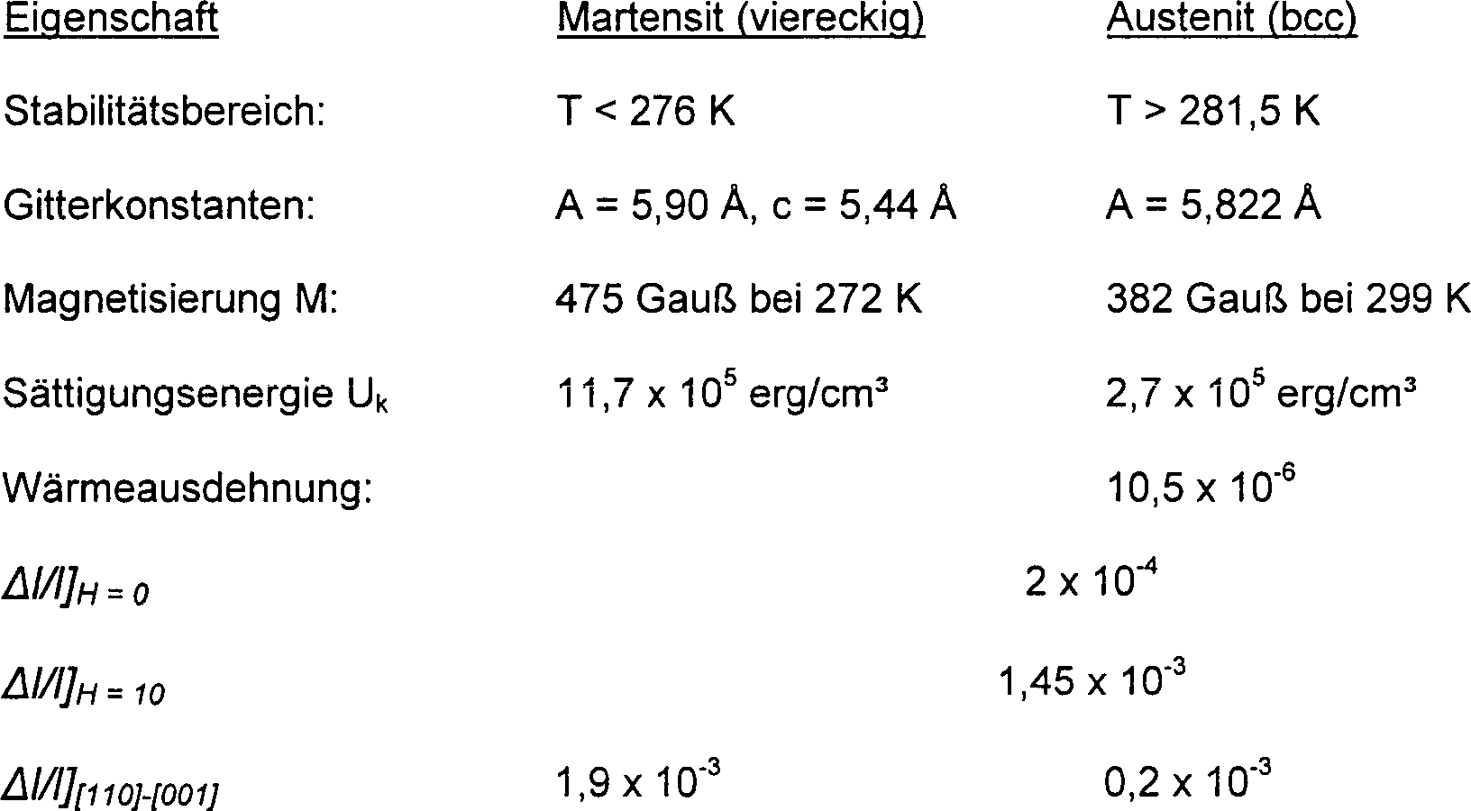
Die Energie, die nötig ist, um die Zwillingsgrenzen zu bewegen, wurde für die Probe aus Ni2MnGa hochgerechnet. Anhand der Magnetisierungsschleifen in der martensitischen Phase lässt sich feststellen, dass bei den Varianten des Materials mit ungünstiger Ausrichtung eine Dichte in der magnetischen Anisotropie-Energie MH/2 von etwa 1,17 × 10⁶ erg/cm3 bzw. etwa 17% von σe/2 zur Verfügung steht, um die Bewegung der Zwillingsgrenze anzusteuern. Aus den gerade beschriebenen quantitativen Ergebnissen wird deshalb deutlich, dass sogar eine stärkere elastische Verformung als der gemessenen elastischen Verformung in der martensitischen Phase zum Ansteuern eines Aktorenhubs zur Verfügung steht. Wie nachstehend noch erläutert wird, wurde erkannt, dass eine Vorbelastung der Probe, zum Beispiel durch mechanische Vorspannung der Probe, eine erhöhte Reaktion auf eine elastische Verformung ermöglichen kann.The energy needed to move the twin boundaries was extrapolated for the Ni 2 MnGa sample. From the magnetization loops in the martensitic phase, it can be seen that in the variants of the material with unfavorable orientation a density in the magnetic anisotropy energy MH / 2 of about 1.17 × 10 6 erg / cm 3 or about 17% of σe / 2 is available to control the movement of the twin boundary. Therefore, from the quantitative results just described, it becomes clear that even more elastic deformation than the measured elastic deformation in the martensitic phase is available for driving an actuator stroke. As will be explained below, it has been recognized that preloading the sample, for example, by mechanically biasing the sample, may allow for increased response to elastic deformation.
Unter Berücksichtigung auch der Charakteristiken im Frequenzverhalten wurden Betätigungsversuche mit Proben aus Ni2MnGa bei Anlegung eines magnetischen Betätigungsfelds mit verschiedenen vorgesehenen Frequenzen durchgeführt. Das Frequenzverhalten erwies sich als sehr gut, sogar über 1 kHz. Die entsprechende Dichte im Leistungsausgang wurde dann bei dem Material bei über 1 kW/kg festgestellt.Taking into account also the characteristics in the frequency behavior, actuation experiments were carried out with samples of Ni 2 MnGa upon application of a magnetic actuation field with different intended frequencies. The frequency response proved to be very good, even over 1 kHz. The corresponding density in the power output was then found in the material at over 1 kW / kg.
Die Erfinder haben erkannt, dass Aktorenmaterialien aus Einzelkristallen wie die Probe aus Ni2MnGa in Einzelkristallform für die interessierenden Aktoren-Einsatzbereiche nicht immer praktisch sind. Einzelkristall-Werkstoffe in der austenitischen Phase können schwierig und in der Herstellung kostspielig sein, und in termetallische Einzelkristall-Zusammensetzungen, die sich erfindungsgemäß magnetisch steuern lassen, sind leicht mechanisch spröde. Außerdem lassen sich Einzelkristall-Werkstoffe nur über einen relativ engen Bereich der Zusammensetzung herstellen, wodurch die Fähigkeit eingeschränkt wird, die physikalischen Eigenschaften des Materials für eine bestimmte Anwendung maßzuschneidern.The inventors have recognized that single crystal actor materials such as the single crystal Ni 2 MnGa sample are not always practical for the actuator uses of interest. Single-crystal materials in the austenitic phase can be difficult and costly to manufacture, and single-crystal termi-metal compositions which can be magnetically controlled according to the invention are easily mechanically brittle. In addition, single crystal materials can only be produced over a relatively narrow range of composition, thereby limiting the ability to tailor the physical properties of the material for a particular application.
Die Erfindung sieht Zusammensetzungen für polykristallines Aktorenmaterial vor, zum Beispiel polykristalline NiMnGa-Zusammensetzungen, für welche sich die magnetische Steuerung der Bewegung der Zwillingsgrenze erzielen lässt und mit welchen die Einschränkungen überwunden werden, die für ein Einzelkristall-Aktorenmaterial gelten. Für den quantitativen Nachweis solcher Werkstoffe wurde das polykristalline NiMnGa-System experimentell untersucht. Die polykristallinen NiMnGa-Zusammensetzungen wurden unter Heranziehung mehrerer Techniken hergestellt. Bei einem ersten Verfahrensbeispiel wurden die gewünschten Bestandteile in Elementform zusammen in Quarzröhrchen unter einer Edelgas-Atmosphäre im Induktionsverfahren zusammen schmelzflüssig gemacht, um kleine Legierungsplättchen bzw. -kügelchen mit dem Durchmesser des Röhrchens zu erzeugen. In einem zweiten Prozess wurden die als Bestandteil vorgesehenen Elemente in einem Schmelzgefäß in einem Vakuum-Ofen geschmolzen. Alternativ wurde eine Säule aus geschmolzenem Metall unter Heranziehung bekannter Saug-Gieß-Techniken durch ein hohles Quarzröhrchen gezogen. Mit diesem Verfahren wird der Schrumpfhohlraum beseitigt, der eine typische Begleiterscheinung bei der Abkühlung eines festgelegten Volumens an Metallschmelze ist; hier lässt sich weiteres geschmolzenes Material aus der Schmelze in das hohle Röhrchen hochziehen, um jeglichen Schrumpfhohlraum zu füllen, der sich gegebenenfalls beim Abkühlen der Säule bildet, und dann von oben nach unten verfestigen.The Invention provides compositions for polycrystalline actor material for example, polycrystalline NiMnGa compositions for which the magnetic control of the movement of the twin boundary achieve and with which the limitations are overcome be that for a single crystal actuator material be valid. For The quantitative detection of such materials was the polycrystalline NiMnGa system experimentally investigated. The polycrystalline NiMnGa compositions were made using several techniques. At a In the first method example, the desired constituents were in elemental form together in quartz tubes under a noble gas atmosphere made molten together in the induction process to small alloy plates or spherules with the diameter of the tube to create. In a second process, the as part of provided elements melted in a melting vessel in a vacuum oven. Alternatively, it became a column of molten metal using known suction casting techniques through a hollow quartz tube drawn. This procedure eliminates the shrinkage cavity, a typical concomitant to the cooling of a fixed volume at molten metal is; leave here Further molten material from the melt into the hollow tube pull up to fill any shrinkage cavity, if any on cooling the column forms, and then solidify from top to bottom.
Beispiel 3Example 3
Ein
großer
Bereich in der Zusammensetzung der polykristallinen Proben aus NiMnGa
wurde mit den gerade beschriebenen Verfahrensweisen hergestellt.
Es wurde festgestellt, dass die Proben mechanisch stark sind, insbesondere
in ihrer Verbindung mit Einzelkristall-Proben aus NiMnGa. Jede Zusammensetzung
wurde hinsichtlich ihrer Curie-Temperatur Tc,
ihrer Phasenübergangs-Temperatur
beim Übergang
in die martensitische Phase, die hier als Tmart bezeichnet
wird, und ihrer Sättigungsmagnetisierung
Ms charakterisiert. Diese drei Charakteristika
sind jeweils auf graphischen Darstellungen der Zusammensetzung in
Dreiecksform in den
Um
eine optimale NiMnGa-Zusammensetzung zu ermitteln, wird zunächst die
Curie-Temperatur der Zusammensetzungen berücksichtigt, wobei auf die graphische
Darstellung in
Die
Phasenübergangs-Temperatur
Tmart für
den Übergang
in die martensitische Phase, die bei den Proben gemessen wurde,
ist in Grad Celsius in
Wie
vorstehend erläutert,
kann eine magnetische Steuerung der martensitischen Zwillingsvarianten nur
bei Zusammensetzungen erreicht werden, bei denen die martensitische
Phase vorhanden ist. Vorzugsweise zeichnet sich das Aktorenmaterial
aus NiMnGa durch die Anwesenheit der martensitischen Phase bei Temperaturen über dem
Gefrierpunkt von Wasser bei 0°C
aus und liegt in noch stärker
bevorzugter Weise nahe bei Zimmertemperatur, also bei 19°C oder darüber. Es
wird nun auf die Graphik in
Es wird festgestellt, dass die Phasenübergangs-Temperatur beim Übergang in die martensitische Phase gegenüber dem Spannungszustand des Materials sehr empfindlich ist und somit steht zu erwarten, das sich die hier angegebenen Werte in Entsprechung zur Bearbeitung einer bestimmten Probe und zur verbleibenden elastischen Verformung verändern. Somit wird erkennbar, dass Legierungen außerhalb des vorzuziehenden Bereichs, der hier definiert wurde, ebenfalls eine Phasenübergangs-Temperatur für den Übergang in den martensitischen Zustand zeigen, welche die Legierung für Einsatzbereiche bei oder über der Zimmertemperatur geeignet macht.It it is found that the phase transition temperature during the transition into the martensitic phase opposite to the stress state of the Material is very sensitive and therefore it is expected that the values given here correspond to the processing a certain sample and the remaining elastic deformation change. Thus, it will be appreciated that alloys outside the preferable range, which has been defined herein, also has a phase transition temperature for the transition in the martensitic state show which the alloy for uses at or above the room temperature makes.
Die Erfinder dieser Anmeldung haben anhand der Analyse der Curie-Temperatur und der Phasenübergangs-Temperatur beim Übergang in die martensitische Phase drei polykristalline NiMnGa-Zusammensetzungen erkannt, die sich besonders gut als Aktorenmaterial gemäß der vorliegenden Erfindung eignen. Die erste – Ni45,6Mn34,1Ga19,3 – zeichnet sich durch eine Curie-Temperatur bei etwa 70°C und eine Phasenübergangs-Temperatur für den Übergang in die martensitische Phase von etwa 43°C aus, die beide deutlich über der Zimmertemperatur liegen. Die zweite gut geeignete Zusammensetzung – Ni18,6Mn32,4Ga19 – zeichnet sich durch eine Curie-Temperatur von etwa 51°C und eine Phasenübergangs-Temperatur für den Übergang in den martensitischen Zustand bei etwa 29°C aus. Für die dritte gut geeignete Zusammensetzung – Ni50,2Mn29,8Ga20 – sind eine Curie-Temperatur von etwa 53°C und eine Phasenübergangs-Temperatur beim Übergang in den martensitischen Zustand bei rund 29°C charakteristisch. Es wird deutlich, dass eine gewisse Berücksichtigung für die Toleranz bei den Messtechniken in angemessener Weise zulässig sein sollte und somit können die für jede der drei hier aufgeführten Zusammensetzungen angegebenen atomaren Fraktionen der Zusammensetzung als Mittelpunkte der Bereiche betrachtet werden, die zu beiden Seiten des Mittelpunkts mehrere Prozentpunkte überspannen.The inventors of this application have identified, on the basis of the analysis of the Curie temperature and the phase transition temperature during the transition into the martensitic phase, three polycrystalline NiMnGa compositions which are particularly suitable as actor material according to the present invention. The first - Ni 45.6 Mn 34.1 Ga 19.3 - is characterized by a Curie temperature at about 70 ° C and a phase transition temperature for the transition to the martensitic phase of about 43 ° C, both distinct above the room temperature. The second well-suited composition - Ni 18.6 Mn 32.4 Ga 19 - is characterized by a Curie temperature of about 51 ° C and a phase transition temperature for the transition to the martensitic state at about 29 ° C. For the third well-suited composition - Ni 50.2 Mn 29.8 Ga 20 - are a Curie temperature of about 53 ° C and a phase transition temperature in the transition in the martensitic state at around 29 ° C characteristic. It will be appreciated that some consideration for the tolerance in the measurement techniques should be reasonably allowable, and thus the atomic fractions of the composition given for each of the three compositions listed herein may be considered as centers of the regions having more than one side of the center Span percentage points.
Berücksichtigt man die drei besonders gut geeigneten Zusammensetzungen, die vorstehend grob umrissen sind, stellt man fest, dass die Zusammensetzung mit der stärksten Magnetisierung, für die auch eine Curie-Temperatur und eine Phasenübergangs-Temperatur beim Übergang in den martensitischen Zustand charakteristisch sind, die beide über Zimmertemperatur liegen, die Zusammensetzung Ni50,2Mn29,8Ga20 ist. Diese Zusammensetzung zeichnet sich durch eine Magnetisierung von etwa 48 emu/g aus. Bei vielen Einsatzgebieten bei Raumtemperatur hat sich diese Zusammensetzung als besonders gut geeignet erwiesen.Considering the three particularly well-suited compositions outlined above, it is noted that the composition with the strongest magnetization, for which a Curie temperature and a phase transition temperature are characteristic in the transition to the martensitic state, are both above room temperature, the composition is Ni 50.2 Mn 29.8 Ga 20 . This composition is characterized by a magnetization of about 48 emu / g. In many applications at room temperature, this composition has been found to be particularly well suited.
Ganz
allgemein kann man gemäß der vorliegenden
Erfindung eine geeignete NiMnGa-Zusammensetzung unter Heranziehung
der graphischen Darstellungen in
Für einige Anwendungsbereiche ist eine polykristalline Legierung der stöchiometrischen Zusammensetzung Ni50Mn25Ga25 vorzuziehen, während jede der verschiedenen polykristallinen Legierungszusammensetzungen, die bei diesem Beispiel beschrieben wurden, als für verschiedene Einsatzbereiche vorzuziehen ermittelt wird. Ganz allgemein haben die Erfinder dieser Anmeldung entdeckt, dass die polykristallinen Legierungen, die durch die Zusammensetzung Ni65–x–yMn20+xGa15+y definiert werden, wobei x zwischen ca. 3 Atom-% liegt und etwa 14 Atom-% liegt und y einen Wert von rund 3 Atom-% bis rund 12 Atom-% hat, einen Bereich der betrieblichen Eignung bieten, die sich gut für eine breite Palette von Einsatzmöglichkeiten des Aktorenmaterials eignen.For some applications, a polycrystalline alloy of stoichiometric composition Ni 50 Mn 25 Ga 25 is preferable, while each of the various polycrystalline alloy compositions described in this example is found to be preferable for various uses. More generally, the inventors of this application have discovered that the polycrystalline alloys defined by the composition Ni 65-x-y Mn 20 + x Ga 15 + y , where x is between about 3 atomic% and about 14 atomic %, and y ranges from about 3 atomic% to about 12 atomic%, providing a range of operational suitability well suited for a wide range of uses of the actuator material.
Beispiel 4Example 4
Zu
einer weiteren experimentellen Analyse der Proben aus polykristallinem
NiMnGa wurde die freie elastische Verformung an der Legierungszusammensetzung
Ni50Mn28Ga22 als Funktion der Temperatur gemessen,
d. h. e0(T), sowohl ohne Anlegen eines Magnetfelds
als auch bei Anlegen eines Magnetfelds von rund 7,95 × 10⁹ A/m (10 kOe). Die gemessene Veränderung
der elastischen Verformung als Funktion des angelegten Feldes ist
in der graphischen Darstellung in
Dabei ist zu beachten, dass im Vergleich zur austenitischen Phase in der martensitischen Phase insgesamt ein Anstieg in der elastischen Verformung festgestellt wird. Außerdem zeigte sich in der durch das Feld induzierten elastischen Verformung eine Spitze bei Annäherung von niedrigeren Temperaturen aus an die Phasenübergangs-Temperatur beim Übergang in den martensitischen Zustand.there It should be noted that compared to the austenitic phase in the martensitic phase overall, an increase in the elastic deformation is detected. Furthermore showed in the field induced elastic deformation a tip on approach from lower temperatures to the transition phase transition temperature in the martensitic state.
Beispiel 5Example 5
Zur
weiteren Charakterisierung der magnetischen Eigenschaften der Proben
aus polykristallinen Legierungen wurde die Schwankung der Magnetisierung
in Abhängigkeit
von der Temperatur an einer Probe einer polykristallinen Legierung
mit der Zusammensetzung Ni50,2Mn29,8Ga20 gemessen.
Die gemessene Veränderung
bei dieser Probe ist gegenüber
der Temperatur in
Unter Berücksichtigung des Bereichs der Zusammensetzungen und der Betriebs-Kennwerte der beim vorstehenden Beispiel beschriebenen polykristallinen Legierungen haben die Erfinder des Weiteren entdeckt, dass sich verschiedene zusätzliche Substitutionen in der Zusammensetzung vornehmen lassen, um eine polykristalline Legierung zu bilden, die einen gewünschten Satz an Betriebs-Kennwerten besitzt. Bei einem ersten solchen Beispiel wird bei der allgemeinen Zusammensetzung Ni65–x–yMn20+xGa15+y, wobei x zwischen ca. 3 Atom-% und etwa 14 Atom-% beträgt und y einen Wert von ca. 3 Atom-% bis etwa 12 Atom-% hat, die Nickel-Komponente durch eine Komponente (NiaFebCoc)65–x–y ersetzt, bei welcher a + b + c = 1 ist, b zwischen etwa Null und ca. 0,6 liegt und c einen Wert zwischen ca. Null und rund 0,6 hat, um die Legierung (NiaFebCoc)65–x–yMn20+xGa15+y zu bilden. Es hat sich gezeigt, dass der Zusatz von Eisen und Kobalt zu der Legierung sowohl die Curie-Temperatur der Legierung als auch die Magnetisierung der Legierung erhöht.Considering the range of compositions and operating characteristics of the polycrystalline alloys described in the above example, the inventors further discovered that various additional substitutions can be made in the composition to form a polycrystalline alloy having a desired set of operating temperatures. Has characteristic values. In a first such example, in the general composition Ni 65-x-y Mn 20 + x Ga 15 + y , where x is between about 3 at% and about 14 at%, and y is about 3 at -% to about 12 atomic%, the nickel component replaced by a component (Ni a Fe b Co c ) 65-x-y , where a + b + c = 1, b between about zero and about 0.6 and c has a value between about zero and about 0.6 to form the alloy (Ni a Fe b Co c ) 65-x-y Mn 20 + x Ga 15 + y . It has been found that the addition of iron and cobalt to the alloy increases both the Curie temperature of the alloy and the magnetization of the alloy.
In gleicher Weise kann bei der allgemeinen Zusammensetzung Ni65–x–yMn20+xGa15+y, wobei x zwischen ca. 3 Atom-% und etwa 14 Atom-% beträgt und y einen Wert von ca. 3 Atom-% bis etwa 12 Atom-% hat, die Mn-Komponente durch eine Komponente (MnaFebCoc)20+x ersetzt werden, bei welcher a + b + c = 1 ist, b zwischen etwa Null und ca. 0,5 liegt und c einen Wert zwischen ca. Null und rund 0,2 hat, um die Legierung Ni65–x–y(MnaFebCoc)20+xGa15+y zu bilden. Es hat sich gezeigt, dass der Zusatz von Eisen und Kobalt zu der Legierung sowohl die Curie-Temperatur als auch die Magnetisierung der Legierung erhöht.Similarly, in the general composition, Ni may be 65-x-y Mn 20 + x Ga 15 + y , where x is between about 3 at% and about 14 at%, and y is about 3 at%. to about 12 atomic%, the Mn component is replaced by a component (Mn a Fe b Co c ) 20 + x in which a + b + c = 1, b is between about zero and about 0.5 and c has a value between about zero and about 0.2 to form the alloy Ni 65-x-y (Mn a Fe b Co c ) 20 + x Ga 15 + y . It has been found that the addition of iron and cobalt to the alloy increases both the Curie temperature and the magnetization of the alloy.
Ebenso kann bei der allgemeinen Zusammensetzung Ni65–x–yMn20+xGa15+y, wobei x zwischen ca. 3 Atom-% und etwa 14 Atom-% beträgt und y einen Wert von ca. 3 Atom-% bis etwa 12 Atom-% hat, die Ga-Komponente durch eine Komponente (GaaSibAlc)15+y ersetzt werden, bei welcher a + b + c = 1 ist und b und c einen Wert zwischen ca. Null und etwa 0,5 haben, um die Legierung Ni65–x–yMn20+x(GaaSibAlc)15+y zu bilden. Die Zusätze an Silizium und Aluminium lassen sich zur Optimierung der Curie-Temperatur und der Phasenübergangstemperatur beim Übergang in den martensitischen Zustand wie auch der Magnetisierung, der Steifigkeit, des Korrosionsverhaltens und anderer Eigenschaften verändern, die für einen bestimmten Einsatzbereich von Interesse sind.Also, in the general composition, Ni may be 65-x-y Mn 20 + x Ga 15 + y , where x is between about 3 at% and about 14 at%, and y is about 3 at% to about 12 atomic%, the Ga component is replaced by a component (Ga a Si b Al c ) 15 + y in which a + b + c = 1 and b and c have a value between about zero and about zero , 5 have to form the alloy Ni 65-x-y Mn 20 + x (Ga a Si b Al c ) 15 + y . The additions of silicon and aluminum can be changed to optimize the Curie temperature and the phase transition temperature at the transition to the martensitic state as well as the magnetization, stiffness, corrosion behavior, and other properties of interest for a particular application.
Anhand dieser Diskussion wird deutlich, dass Legierungen der allgemeinen Form (NiaFebCoc)65–x–y(MndFeeCof)20+x(GagSihAli)15+y, bei denen x zwischen etwa 3 Atom-% und ca. 14 Atom-% liegt und y einen Wert von etwa 3 Atom-% bis ca. 12 Atom-% besitzt und wobei a + b + c = 1 ist, wobei d + e + f = 1 ist und g + h + i = 1 ist, gemäß der Erfindung als magnetisch ansteuerbares Aktorenmaterial verwendet werden kann und in angemessener Weise praktisch in polykristalliner Form in einer Zusammensetzung hergestellt werden kann, die sich bei vernünftigen Temperaturen betreiben lassen.From this discussion, it is clear that alloys of the general form (Ni a Fe b Co c ) 65-x-y (Mn d Fe e Co f ) 20 + x (Ga g Si h Al i ) 15 + y where x is between about 3 at.% and about 14 at.% and y has a value from about 3 at.% to about 12 at.%, and where a + b + c = 1, where d + e + f = Is 1 and g + h + i = 1, can be used in accordance with the invention as a magnetically actuatable actuator material and can be conveniently made in practical polycrystalline form in a composition that can be operated at reasonable temperatures.
Die Erfinder haben durch Versuche auch andere in Frage kommende magnetisch ansteuerbare Werkstoffe analysiert, darunter das hcp-fcc-System ε CoMn mit hoher Anisotropie innerhalb des Bereichs an Zusammensetzungen, in dem der Übergang in die martensitische Phase nahe der Zimmertemperatur oder über dieser liegt; diesen Bereich findet man bei einem Mn-Gehalt, der zwischen etwa 12% und rund 30% liegt. Es wurde festgestellt, dass die in diesem System aufgebauten Spannungen geringer sind als bei dem NiMnGa-System. Es wurde entdeckt, dass kleine Legierungszusätze, zum Beispiel ein Nickelzusatz, zu der Legierung die elastische Verformung an der Zwillingsgrenze verbessern kann, indem sie die fcc-Phasenbildung fördert und dementsprechend den Übergang in die martensitische Phase bei vergleichsweise geringeren Mn-Konzentrationen unterstützt. Solche Zusammensetzungen zeichnen sich durch eine stärkere Magnetisierung aus, wodurch ein angelegtes Magnetfeld einen größeren Energieunterschied über die martensitischen Zwillingsgrenzen erzeugen kann, wie vorstehend schon erläutert wurde. Dieser größere Energieunterschied neigt seinerseits dazu, die Bewegung der Zwillingsgrenze, die durch ein angelegtes Magnetfeld herbeigeführt wird, zu vereinfachen. Die Eigenschaften des CoMn-Systems bei der magnetischen Aktorenfunktion lassen sich gemäß der vorliegenden Erfindung für einen bestimmten Einsatzbereich durch den Zusatz von Cr, Pt, Pd, Au, Nb oder ein anderes geeignetes Element maßschneidern, das vorzugsweise in einem Anteil von bis zu etwa 10 Atom-% vorliegt. Außerdem haben die Erfinder ganz allgemein erkannt, dass der Bereich der Legierungszusammensetzung von CoaMnb – wobei a zwischen etwa 60 und 90 liegt und b einen Wert zwischen etwa 10 und rund 40 hat – einen Bereich für die Aktorenmaterialien bildet, welche Betriebskennwerte aufweisen, die sich für einen bestimmen Einsatzbereich maßschneidern lassen.The inventors have also experimentally analyzed other candidate magnetically-responsive materials, including the hcp-fcc system ε CoMn with high anisotropy within the range of compositions in which the transition to the martensitic phase is near room temperature or above; This range is found at an Mn content of between about 12% and about 30%. It was found that the voltages built up in this system are lower than in the NiMnGa system. It has been discovered that small alloying additions, for example nickel addition, to the alloy can improve the elastic deformation at the twin boundary by promoting fcc phase formation and, accordingly, assisting the transition to the martensitic phase at relatively lower Mn concentrations. Such compositions are characterized by a stronger magnetization tion, whereby an applied magnetic field can generate a larger energy difference across the martensitic twin boundaries, as already explained above. This greater energy difference, in turn, tends to facilitate the movement of the twin boundary caused by an applied magnetic field. The properties of the CoMn system in the magnetic actuator function can be tailored according to the present invention for a particular application by the addition of Cr, Pt, Pd, Au, Nb or another suitable element, preferably in a proportion of up to about 10 Atomic% is present. In addition, the inventors have generally recognized that the range of alloy composition of Co a Mn b - where a is between about 60 and 90 and b is between about 10 and about 40 - forms an area for the actuator materials having operating characteristics. which can be tailored for a specific area of application.
Wie sich aus den bisherigen Erläuterungen erkennen lässt, ist es möglich, eine breite Palette von Legierungen zu konzipieren, um ein Aktorenmaterial herzustellen, das die Eigenschaft der magnetischen Steuerung der Zwillingsgrenze gemäß der Erfindung besitzt. Die vorstehend dargestellten Werkstoffe sind nur Beispiele und sollen keine Einschränkung darstellen.As from the previous explanations to recognize Is it possible, to design a wide range of alloys to be an actor material which is the property of the magnetic control of the Twin border according to the invention has. The materials shown above are only examples and are not meant to be limiting represent.
Bei einem ausgewählten erfindungsgemäßen Aktorenmaterial haben die Erfinder dieser Anmeldung erkannt, dass die Größe und Form des Aktorenmaterials einen Einfluss auf die verschiedenen Eigenschaften des Materials im Betriebsverhalten nehmen kann. Wenn zum Beispiel ein großer Aktorenhub erwünscht ist, sollte vorzugsweise ein vergleichsweise langes und dünnes Element aus dem Aktorenmaterial verwendet werden. Wenn eine starke Kraft beim Betätigungshub erwünscht ist, wird vorzugsweise für das Aktorenelement eine Fläche mit großem Querschnitt konzipiert. Wenn umgekehrt eine Betätigung mit hoher Geschwindigkeit gewünscht wird, wird ein dünneres Element bevorzugt, um die Ausbildung von Wirbelströmen zu verringern, die im Ansprechen auf ein angelegtes magnetisches Wechselfeld in dem Material gebildet werden.at a selected one actor material according to the invention The inventors of this application have recognized that the size and shape of the actuator material has an influence on the different properties of the Material in the operating behavior can take. If, for example, a greater Actuator stroke desired is, should preferably a comparatively long and thin element be used from the actor material. If a strong force during the actuating stroke he wishes is preferably for the actuator element a surface with big Cross-section designed. Conversely, if high speed operation is desired, becomes a thinner Element preferred to reduce the formation of eddy currents, the in response to an applied alternating magnetic field in the Material are formed.
Es wird deutlich, dass bei der Konzipierung der Form und der Größe des Aktorenelements an den gewünschten Leistungsmerkmalen Abstriche gemacht werden müssen. Wenn zum Beispiel ein Aktorenelement für große Kraft und hohe Geschwindigkeit gewünscht wird, dann werden gemäß der Erfindung vorzugsweise Laminatfolien aus dem Aktorenmaterial hergestellt, die übereinander gestapelt und durch Isolierlagen in herkömmlicher Weise voneinander getrennt werden, so dass einerseits die Wirbelströme reduziert werden, aber andererseits eine wirksame große Querschnittsfläche vorgesehen wird. Die Kosten und die Komplexität des Herstellungsverfahrens bei einer solchen Laminatstruktur der Aktoren müssen natürlich im Zusammenhang mit dem Zugewinn an Leistungsverhalten betrachtet werden, der dadurch erzielt wird. Wie daraus deutlich wird, ist es möglich, eine breite Palette an rechteckförmigen, stabförmigen Formen, Formen als dünner Film, als Partikel, Draht etc. des Aktorenmaterials zu verwenden, und gemäß der Erfindung wird es bevorzugt, dass die Art der mechanischen Verbindungen beim jeweiligen Einsatzgebiet des Aktorenelements im Zusammenhang mit den Kriterien des Leistungsverhaltens im Aktoreneinsatz berücksichtigt werden, wenn eine optimale Form und eine optimale Größe des Aktorenmaterials ermittelt werden.It it becomes clear that in the design of the shape and size of the actuator element to the desired Performance features must be made. If, for example, a Actuator element for size Force and high speed is desired, then be according to the invention preferably laminate films produced from the actuator material, the one above the other stacked and by insulating layers in a conventional manner from each other be separated, so that on the one hand reduces the eddy currents but on the other hand provide an effective large cross-sectional area becomes. The cost and complexity of the manufacturing process in such a laminate structure of the actuators must of course in connection with the Gain in performance achieved by doing so becomes. As it becomes clear, it is possible to have a wide range on rectangular, rod-shaped Shapes, shapes as thinner Film to use as particles, wire etc. of the actuator material and according to the invention It is preferred that the nature of the mechanical connections during respective application of the actuator element in connection with the Criteria of performance in actuator use considered if optimal shape and size of the actuator material be determined.
Es hat sich gezeigt, dass bei einem bestimmten Aktorenelement die Reaktion auf magnetische Auslösung durch mehrere verschiedene Verfahrensabläufe optimiert werden kann. Im Betrieb wird über die kurze Abmessung vorzugsweise ein statisches magnetisches Vorspannfeld angelegt und wird über eine andere Abmessung des Materials, d. h. senkrecht zum Vorspannfeld, ein magnetisches Wechselfeld zur Betätigung angelegt. Vorzugsweise wird vor Anlegung des Betätigungsfelds das Aktorenelement mehrmals unter Anlegung des Vorspannfelds erwärmt und abgekühlt. Damit wird das Material unter Drehung der Varianten zur Ausrichtung auf das Vorspannfeld vorbereitet; danach richtet sich eine zunehmende Konzentration an c-Achsen in dem Material parallel zu dem Vorspannfeld aus, wenn zusätzliche Zyklen zur Erwärmung und Abkühlung vollständig ausgeführt werden.It has been shown that at a certain actuator element, the reaction on magnetic release can be optimized by several different procedures. In operation is over the short dimension preferably a static magnetic bias field created and becomes over another dimension of the material, d. H. perpendicular to the preload field, an alternating magnetic field applied for actuation. Preferably is before the application field heated the actuator element several times under application of the bias field and cooled. This aligns the material while the variants are rotated prepared for the header field; after that, an increasing is directed Concentration of c-axes in the material parallel to the bias field off, if additional Cycles for heating and cooling off Completely accomplished become.
Wenn die Vorspann-Ausrichtung vor der Betätigung abgeschlossen ist, führt die Anlegung eines magnetischen Betätigungsfelds in einer Richtung senkrecht zum Vorspannfeld zu einer Drehung der martensitischen Magnetisierungsvektoren und Zelleinheiten um 90° und resultiert in einer Maximierung der elastischen Verformung der Zwillingsgrenze, welche durch den Aktorenhub aufgebaut werden kann. Ganz allgemein lässt sich feststellen, dass mit dem Ziel, dass das Aktorenelement die stärkstmögliche Ausbildung einer elastischen Verformung erhält, ein statisches Vorspannfeld in einer ersten Richtung angelegt wird und das Betä tigungsfeld in einer zweiten Richtung angelegt wird, die so gewählt wird, dass der Dreheffekt bei der Magnetisierung und die entsprechende Bewegung der Zwillingsgrenze maximiert werden, die mit der Drehung der Magnetisierung einhergeht. Bei einer bevorzugten Arbeitstechnik wird das magnetische Betätigungsfeld über die längste Abmessung des Elements aus Aktorenmaterial angelegt, um einen Hub entlang dieser Abmessung herbeizuführen. Es wurde erkannt, dass das Aktorenmaterial abwechselnd vorgespannt werden kann, z. B. durch eine mechanische Vorspann-Ausbildung, um vor der Anlegung des magnetischen Betätigungsfeldes Varianten so auszurichten, dass sie eine größtmögliche Reaktion auf elastische Verformungen in einem magnetischen Betätigungsfeld ausrichten.When the bias alignment is completed prior to actuation, the application of a magnetic actuation field in a direction perpendicular to the bias field results in a rotation of the martensitic magnetization vectors and cell units by 90 ° and results in maximizing the elastic deformation of the twin boundary established by the actuator stroke can be. In general, it can be stated that, with the aim of giving the actuator element the strongest possible formation of elastic deformation, a static bias field is applied in a first direction and the actuator field is applied in a second direction which is chosen such that the rotational effect in the magnetization and the corresponding movement of the twin boundary, which is accompanied by the rotation of the magnetization. In a preferred technique, the magnetic actuation field is applied across the longest dimension of the actuator material element to provide a stroke along that dimension. It has been recognized that the actor material can be biased alternately, e.g. B. by a me chanical biasing design to align variants prior to application of the magnetic field of actuation so as to align the greatest possible response to elastic deformations in a magnetic field of action.
Wie sich daraus erkennen lässt, kann das magnetische Vorspann- und Betätigungsfeld von verschiedenen Feldquellen erzeugt werden, die innerhalb einer breiten Palette liegen. Zum Beispiel kann das Vorspannfeld unter Verwendung eines Dauermagneten oder eines Elektromagneten aufgebaut werden, wobei das so erzeugte Betätigungsfeld mit Wicklungen arbeitet, die um die entsprechende Abmessung des Aktorenelements gewickelt sind, wobei diesem die gerade vorstehend gegebene Erläuterung der Ausrichtung zugrunde liegt. Wenn bei den untersuchten NiMnGa-Systemen das Betätigungsfeld über die kurze Abmessung des Aktorenelements angelegt wird, so zeigt sich im Ansprechen auf das Feld eine Längendehnung des Elements, während das Element sich im Ansprechen auf ein Feld, das quer zur langen Abmessung des Betätigungselements angelegt wird, zusammenzieht. Daraus lässt sich ablesen, dass somit eine gewünschte Richtung des Betätigungshubs durch eine entsprechende Auswahl der Ausrichtung des angelegten Feldes maßgeschneidert werden kann.As can be seen from it, can the magnetic bias and actuation field of different Field sources are generated within a wide range lie. For example, the header field may be using a Permanent magnet or an electromagnet are constructed, wherein the field of activity thus generated works with windings that are around the appropriate dimension of the Actuator element are wound, with this just above given explanation the orientation is based. If in the investigated NiMnGa systems the field of activity over the short dimension of the actuator element is applied, it turns out in response to the field, an elongation of the element while the Element in response to a field that is transverse to the long dimension of the actuating element is created, contracts. It can be seen from this that thus a desired one Direction of the actuating stroke by an appropriate selection of the orientation of the created Field custom made can be.
Die Eigenschaften der erfindungsgemäßen Aktorenmaterialien bezüglich starker elastischer Verformung, großer Kraft, hoher Geschwindigkeit und Verschiebung mit großem Hub richten sich in überlegener Weise auf eine große Palette von Einsatzbereichen für die Aktorenfunktion. Die Aktorenmaterialien eignen sich gut für viele Einsatzzwecke, die üblicherweise unter Verwendung von Legierungen mit Formgedächtnis angesprochen werden, worunter die Steuerung von Ventilen und Pumpen, die Steuerung der Einspritzung von Fluiden und der Ab gabe von Fluiden und eine große Palette von Einsatzbereichen fallen, bei denen eine hochpräzise Messwertwandlung gefordert wird. Zum Beispiel können die Aktorenmaterialien bei mikro-elektromechanischen Systemen eingesetzt werden, zu denen Systeme zur Mikropositionierung, Robotersysteme und Geräte und Vorrichtungen in der Biomedizin und der Chirurgie gehören, wie beispielsweise jene, bei denen eine präzise Steuerung erforderlich ist.The Properties of the actor materials according to the invention in terms of strong elastic deformation, great force, high speed and shift with big Hub are in superior Way on a big one Range of uses for the actor function. Actuator materials are good for many Uses that are usually be addressed using shape memory alloys, including the control of valves and pumps, the control of Injection of fluids and the release of fluids and a wide range fall from areas of application where a high-precision measurement conversion is required. For example, you can the Aktorenmaterialien used in micro-electromechanical systems to which systems for micropositioning, robotic systems and devices and Devices in biomedicine and surgery include, as well For example, those where precise control is required is.
Die erfindungsgemäßen Aktorenmaterialien eignen sich auch gut für Systeme zur Schwingungskontrolle, z. B. bei einem System, bei welchem der Aktor es ermöglicht, dass eine Regelschleife mit negativer Rückmeldung Schwingungen bei Maschinen oder an einem Maschinenteil ausgleicht. In ähnlicher Weise können die Aktorenmaterialien bei Systemen zur Oberflächenkontrolle eingesetzt werden, wie beispielsweise Systemen, die zum Regeln und Kontrollieren der Position einer Oberfläche einer Tragfläche verwendet werden, um so eine präzise passende Auslegung für Szenarien mit Nachlauf und Auftrieb zu erzielen. Systeme aus intelligenten Materialien, die eine intelligente Reaktion auf ihre Umgebung herbeiführen können, werden mit den Aktorenmaterialien ebenfalls gut abgedeckt; hierbei macht das Material eine Messwertwandler-Reaktion mit hoher Geschwindigkeit und hoher Präzision auf einen erfassten Eingangsparameter möglich. Wie sich daraus ersehen lässt, können mittels der magnetischen Ansteuerung der Aktorenmaterialien Veränderungen bei einer komplizierten Form in der Weise herbeigeführt werden, dass ein praktischer Einsatz solcher Aktoren, für welche sich herkömmliche Aktorensysteme nicht problemlos eignen, hier erzielt werden kann.The actor materials according to the invention are also good for Systems for vibration control, z. B. in a system in which the actor makes it possible that a control loop with negative feedback vibrations at Machines or on a machine part balances. In similar Way can the Actor materials are used in surface control systems, such as systems used to control and control the Position of a surface a wing used to be as precise suitable design for To achieve scenarios with caster and lift. Systems of intelligent Materials that can bring about an intelligent response to their environment also well covered with the actor materials; doing this the material performs a transducer response at high speed and high precision possible to a detected input parameter. As it turns out leaves, can by means of the magnetic activation of the actuator materials changes be brought about in a complicated shape in the way that a practical use of such actuators, for which conventional Actuator systems are not easily suitable, can be achieved here.
In diesen Ausführungen werden nur einzelne unter den vielen verschiedenen Anwendungsgebieten hervorgehoben, auf die sich die erfindungsgemäßen Aktorenmaterialien beziehen. Jede Anwendung, für welche ein Betätigungsmechanismus mit vergleichsweise großem Hub, mit hoher Geschwindigkeit und starker elastischer Verformung bevorzugt wird, ist für den Einsatz der Aktorenmaterialien gut geeignet. Selbstverständlich ist es offensichtlich, dass der Fachmann gegebenenfalls verschiedene Modifizierungen und Ergänzungen an den vorstehend beschriebenen Ausführungsbeispielen des Aktorenmaterials vornehmen kann, ohne dabei vom Umfang dieses Beitrags zu diesem Fachgebiet abzuweichen, wie er durch den Gegenstand der Ansprüche definiert wird.In these statements only individual ones among the many different application areas are highlighted, on which the actor materials according to the invention Respectively. Any application, for which is an actuating mechanism with comparatively large Stroke, with high speed and strong elastic deformation is preferred is for the use of Aktorenmaterialien well suited. Of course it is it is obvious that the skilled person may be different Modifications and additions to the embodiments of the actuator material described above without departing from the scope of this article Depart from the field as defined by the subject-matter of the claims becomes.
Text für die Zeichnungen (in der Reihenfolge der Zeichnungsblätter)Text for the drawings (in order the drawing sheets)
- FORCE = KRAFTFORCE = POWER
- SAMPLE SIZE = GRÖSSE DER PROBESAMPLE SIZE = SIZE THE SAMPLE
- STRAIN = ELASTISCHE VERFORMUNGSTRAIN = ELASTIC FORMING
- STRESS = BELASTUNGSTRESS = BURST
- STRAIN = ELASTISCHE VERFORMUNGSTRAIN = ELASTIC FORMING
- TEMPERATURE = TEMPERATURTEMPERATURE = TEMPERATURE
- STRAIN = ELASTISCHE VERFORMUNGSTRAIN = ELASTIC FORMING
- MAGNETIC FIELD = MAGNETFELDMAGNETIC FIELD = MAGNETIC FIELD
- STRAIN = ELASTISCHE VERFORMUNGSTRAIN = ELASTIC FORMING
- CURIE TEMPERATURE = CURIE-TEMPERATURCURIE TEMPERATURE = CURIE TEMPERATURE
- MARTENSITIC START TEMPERATURE = MARTENSITISCHE AUSGANGSTEMPERATURMARTENSITIC START TEMPERATURE = MARTENSITIC OUTPUT TEMPERATURE
- SATURATION MAGNETIZATION = SÄTTIGUNGS-MAGNETISIERUNGSATURATION MAGNETIZATION = SATURATION MAGNETIZATION
- Martensite = MartensitMartensite = Martensite
- Austenite = AustenitAustenite = austenite
- MAGNETIZATION = MAGNETISIERUNGMAGNETIZATION = MAGNETIZATION
- TEMPERATURE (KELVIN) = TEMPERATUR (KELVIN)TEMPERATURE (KELVIN) = TEMPERATURE (KELVIN)
Claims (17)
Applications Claiming Priority (3)
| Application Number | Priority Date | Filing Date | Title |
|---|---|---|---|
| US2395896P | 1996-08-19 | 1996-08-19 | |
| US23958P | 1996-08-19 | ||
| PCT/US1997/014531 WO1998008261A1 (en) | 1996-08-19 | 1997-08-18 | High-strain, magnetic field-controlled actuator materials |
Publications (2)
| Publication Number | Publication Date |
|---|---|
| DE69729219D1 DE69729219D1 (en) | 2004-06-24 |
| DE69729219T2 true DE69729219T2 (en) | 2005-05-25 |
Family
ID=21818127
Family Applications (1)
| Application Number | Title | Priority Date | Filing Date |
|---|---|---|---|
| DE69729219T Expired - Fee Related DE69729219T2 (en) | 1996-08-19 | 1997-08-18 | HIGH MECHANICAL VOLTAGE MATERIALS FOR MAGNETIC FIELD-CONTROLLED ACTUATOR |
Country Status (5)
| Country | Link |
|---|---|
| US (1) | US5958154A (en) |
| EP (1) | EP0958618B1 (en) |
| AT (1) | ATE267462T1 (en) |
| DE (1) | DE69729219T2 (en) |
| WO (1) | WO1998008261A1 (en) |
Families Citing this family (47)
| Publication number | Priority date | Publication date | Assignee | Title |
|---|---|---|---|---|
| FI101563B (en) * | 1995-07-11 | 1998-07-15 | Adaptamat Tech Oy | A method for controlling the orientation of a twin structure and the actuators used therein |
| JP3732931B2 (en) * | 1997-10-29 | 2006-01-11 | 本田技研工業株式会社 | Metal structure having curved portion and method for manufacturing the same |
| US6747377B2 (en) * | 1998-01-12 | 2004-06-08 | Kari M. Ullakko | Method for producing motion and force by controlling the twin structure orientation of a material and its uses |
| FI982407A0 (en) * | 1998-03-03 | 1998-11-06 | Adaptamat Tech Oy | Controls and devices |
| CO5270018A1 (en) * | 1999-12-11 | 2003-04-30 | Glaxo Group Ltd | MEDICINAL DISTRIBUTOR |
| US20030079744A1 (en) | 1999-12-11 | 2003-05-01 | Bonney Stanley George | Medicament dispenser |
| AU2001233073A1 (en) * | 2000-01-28 | 2001-08-07 | The United States Of America As Represented By The Secretary Of The Navy | Magnetostrictive devices and methods using high magnetostriction, high strength fega alloys |
| FI117811B (en) | 2000-05-15 | 2007-02-28 | Nokia Corp | Device and method for implementing a key |
| US20040050385A1 (en) * | 2000-10-20 | 2004-03-18 | Bonney Stanley George | Inhaler |
| GB0025749D0 (en) * | 2000-10-20 | 2000-12-06 | Glaxo Group Ltd | Inhaler |
| EP1219313A1 (en) | 2000-12-29 | 2002-07-03 | Instrumentarium Corporation | Liquid discharging apparatus and magneto-shape-memory type valve |
| US20110301569A1 (en) | 2001-01-20 | 2011-12-08 | Gordon Wayne Dyer | Methods and apparatus for the CVCS |
| US8308874B1 (en) | 2001-01-29 | 2012-11-13 | The United States Of America As Represented By The Secretary Of The Navy | Magnetostrictive materials, devices and methods using high magnetostriction, high strength FeGa and FeBe alloys |
| WO2002064847A1 (en) * | 2001-02-13 | 2002-08-22 | University Of Maryland | A new ferromagnetic shape memory alloy system |
| EP1260365B1 (en) | 2001-05-17 | 2005-03-30 | Veslatec Oy | Ink blade adjusting mechanism |
| US20030107013A1 (en) * | 2001-12-12 | 2003-06-12 | Alfred Pappo | Variable valve with an electromagnetically-elongated actuator |
| CN1272464C (en) * | 2002-04-27 | 2006-08-30 | 艾默生电气(中国)投资有限公司 | Magnetic and heating treatment method to improve magnetically driven reversible strain property of polycrystalline Ni2 MnGa |
| US6803846B2 (en) * | 2002-10-23 | 2004-10-12 | Honda Motor Co., Ltd. | Actuator |
| US7246489B2 (en) * | 2003-02-26 | 2007-07-24 | Mide Technology Corporation | Position control actuator system |
| EP1663519A1 (en) * | 2003-03-03 | 2006-06-07 | Adaptive Materials Technology Oy | A damping and actuating apparatus comprising magnetostrictive material, a vibration dampening device and use of said apparatus |
| US7564152B1 (en) | 2004-02-12 | 2009-07-21 | The United States Of America As Represented By The Secretary Of The Navy | High magnetostriction of positive magnetostrictive materials under tensile load |
| WO2005098985A1 (en) * | 2004-04-05 | 2005-10-20 | Massachusetts Institute Of Technology | Magnetic actuator drive for actuation and resetting of magnetic actuation materials |
| DE102004056282A1 (en) * | 2004-11-22 | 2006-05-24 | Abb Patent Gmbh | Switching device for an electronic assembly comprises a thermal and electromagnetic circuit breaker having a snap-on mounting interacting with an impact anchor |
| DE102004056280A1 (en) * | 2004-11-22 | 2006-05-24 | Abb Patent Gmbh | Protective switch with magnetic release for e.g. motor or circuit protection, is made from alloy with magnetic shape memory |
| DE102004056279A1 (en) * | 2004-11-22 | 2006-05-24 | Abb Patent Gmbh | Protective switch with magnetic and thermal release for e.g. motor or circuit protection, is made from alloy with combined thermal- and magnetic shape memory |
| WO2006056335A1 (en) * | 2004-11-22 | 2006-06-01 | Abb Patent Gmbh | Switching equipment comprising an electromagnetic trip device |
| WO2006091665A2 (en) * | 2005-02-23 | 2006-08-31 | Massachusetts Institute Of Technology | Acoustic pulse actuator |
| US7473028B1 (en) * | 2005-04-22 | 2009-01-06 | The Ohio State University | Method and device for investigation of phase transformations in metals and alloys |
| US20070036731A1 (en) * | 2005-08-13 | 2007-02-15 | Collegium Pharmaceutical, Inc. | Topical Delivery with a Carrier Fluid |
| EP1949399A1 (en) * | 2005-11-15 | 2008-07-30 | Abb Ag | Magnetostrictive electrical switching device |
| WO2007066555A1 (en) | 2005-12-05 | 2007-06-14 | Japan Science And Technology Agency | Co BASED ALLOY AND PROCESS FOR PRODUCING THE SAME |
| JP2007281009A (en) * | 2006-04-03 | 2007-10-25 | Yaskawa Electric Corp | Functional composite material |
| JP5215855B2 (en) | 2006-08-23 | 2013-06-19 | 独立行政法人科学技術振興機構 | Fe-based alloy and manufacturing method thereof |
| WO2008049124A2 (en) * | 2006-10-19 | 2008-04-24 | Boise State University | Magnetomechanical transducer, and apparatus and methods of harvesting energy |
| WO2008061166A2 (en) * | 2006-11-14 | 2008-05-22 | Boise State University | Multi-state memory and multi-functional devices comprising magnetoplastic or magnetoelastic materials |
| US7964290B2 (en) * | 2007-08-30 | 2011-06-21 | Boise State University | Magnetic material with large magnetic-field-induced deformation |
| US8586194B2 (en) * | 2007-08-30 | 2013-11-19 | Boise State University | Polycrystalline foams exhibiting giant magnetic-field-induced deformation and methods of making and using same |
| DE102007055686A1 (en) | 2007-11-21 | 2009-05-28 | Johar Muhammad Batu Pahat Akmal | Brake system for brake rotary units, comprises brake mechanism which uses active material and compensates for wear, where active material has controlled degree of expansion and tension |
| DE102008001005B4 (en) | 2008-04-04 | 2011-06-22 | Karlsruher Institut für Technologie, 76131 | A method for producing a composite layer with epitaxially grown layers of a magnetic shape memory material and composite layer with epitaxial layers of a magnetic shape memory material and its use |
| WO2009147135A1 (en) | 2008-06-02 | 2009-12-10 | Leibniz-Institut Für Festkörper- Und Werkstoffforschung Dresden E.V. | Construction element made of a ferromagnetic shape memory material and use thereof |
| US8487487B2 (en) * | 2008-07-15 | 2013-07-16 | Ethicon Endo-Surgery, Inc. | Magnetostrictive actuator of a medical ultrasound transducer assembly, and a medical ultrasound handpiece and a medical ultrasound system having such actuator |
| DE102010010801B4 (en) * | 2010-03-09 | 2013-02-21 | Eto Magnetic Gmbh | actuator |
| FI20116196L (en) | 2011-11-29 | 2013-05-30 | Adaptamat Tech Oy | METHOD FOR DETECTING AND REGULATING VOLTAGE INDUCED IN AN ELEMENT OF A MAGNETIC MEMORY METAL ALLOY AND ACTUATOR AND SENSOR OF A MAGNETIC MEMORY METAL ALLOY |
| US9901420B2 (en) | 2014-02-25 | 2018-02-27 | Ormco Corporation | Orthodontic appliances including ferromagnetic shape memory alloys and methods of orthodontic treatment using same |
| DE102015221929A1 (en) * | 2015-11-09 | 2017-05-11 | Carl Zeiss Smt Gmbh | Arrangement for a lithography system and lithography system |
| CN105803266B (en) * | 2016-04-05 | 2017-06-20 | 南京工程学院 | A kind of low startup limit stress rare earth magnetic control shape memory alloy and preparation method thereof |
| DE102017114930A1 (en) * | 2017-07-04 | 2019-01-10 | Eto Magnetic Gmbh | ejector |
Family Cites Families (2)
| Publication number | Priority date | Publication date | Assignee | Title |
|---|---|---|---|---|
| SU1611980A1 (en) * | 1988-08-23 | 1990-12-07 | Институт металлофизики АН УССР | Alloy with shape memory effect |
| FI101563B (en) * | 1995-07-11 | 1998-07-15 | Adaptamat Tech Oy | A method for controlling the orientation of a twin structure and the actuators used therein |
-
1997
- 1997-08-18 AT AT97938403T patent/ATE267462T1/en not_active IP Right Cessation
- 1997-08-18 WO PCT/US1997/014531 patent/WO1998008261A1/en active IP Right Grant
- 1997-08-18 DE DE69729219T patent/DE69729219T2/en not_active Expired - Fee Related
- 1997-08-18 EP EP97938403A patent/EP0958618B1/en not_active Expired - Lifetime
- 1997-08-18 US US08/914,669 patent/US5958154A/en not_active Expired - Fee Related
Also Published As
| Publication number | Publication date |
|---|---|
| EP0958618A1 (en) | 1999-11-24 |
| EP0958618B1 (en) | 2004-05-19 |
| DE69729219D1 (en) | 2004-06-24 |
| WO1998008261A1 (en) | 1998-02-26 |
| ATE267462T1 (en) | 2004-06-15 |
| US5958154A (en) | 1999-09-28 |
Similar Documents
| Publication | Publication Date | Title |
|---|---|---|
| DE69729219T2 (en) | HIGH MECHANICAL VOLTAGE MATERIALS FOR MAGNETIC FIELD-CONTROLLED ACTUATOR | |
| DE2516749C3 (en) | Process for the production of metal bodies with repeatedly reversible shape change capability | |
| DE69631346T2 (en) | Drive to generate motion and force by controlling the double structure of a material | |
| EP0674769B1 (en) | Magneto-resistive sensor with a synthetic anti-ferromagnet, and a method of producing the sensor | |
| DE69130351T3 (en) | Method of making a GMR article | |
| DE69910014T2 (en) | BAR PROBE FOR POWER MICROSCOPE | |
| DE102006008257B4 (en) | A spin valve-type magnetoresistive multi-layer system having a magnetically softer multi-layer electrode and the use thereof | |
| DE102009007479A1 (en) | Thin-film magnetic sensor | |
| WO2000002006A2 (en) | Method for regulating the magnetization of the bias layer of a magnetoresistive sensor element, sensor element or sensor element system processed according to said method and sensor element and sensor substrate suitable for the implementation of said method | |
| DE19934989B4 (en) | A composite magnetic member, a method of manufacturing the ferromagnetic member thereof, and a method of manufacturing the non-magnetic member thereof | |
| DE102005038891B4 (en) | Actuator device, in particular for an injection device | |
| DE102007043263A1 (en) | Information converter and method for its production | |
| EP0460291A2 (en) | Magnetic field sensitive apparatus with several magnetic field sensors | |
| DE10258860A1 (en) | Magnetoresistive layer system and sensor element with this layer system | |
| DE10196450B3 (en) | Metallurgical and mechanical compensation of the temperature behavior of terbium-based rare earth magnetostrictive alloys | |
| DE102017122123A1 (en) | Thin-film magnetic sensor | |
| DE102009023479B4 (en) | Component made of a ferromagnetic shape memory material and its use | |
| EP0502397B1 (en) | Preparation process for soft magnetic Fe-containing material with high saturation magnetisation and ultrafine structure | |
| DE19830343C1 (en) | Artificial antiferromagnetic layer manufacturing method for MR sensor, involves affecting symmetry of antiferromagnetic layer partially by mask to adjust orientation of magnetization of bias layer | |
| DE102010050754B4 (en) | Improved sensor / actuator body | |
| DE10142998A1 (en) | Shape memory composite for actuator includes two shape memory alloys with phase transitions occurring in nested temperature hysteresis bands | |
| DE4030476A1 (en) | MAGNETIC STORAGE AND ITS MAGNETIC ALLOY | |
| DE2112183A1 (en) | Non-magnetic material with a constant modulus of elasticity | |
| DE102008026241A1 (en) | Inhomogeneous compounds with high magnetoresistance, their production and use | |
| DE102016209542A1 (en) | Pressure sensor, pressure sensor arrangement, method for detecting a pressure |
Legal Events
| Date | Code | Title | Description |
|---|---|---|---|
| 8364 | No opposition during term of opposition | ||
| 8339 | Ceased/non-payment of the annual fee |