DE69531265T2 - Optical disc and method and apparatus for recording on and then reproducing information from that disc - Google Patents

Optical disc and method and apparatus for recording on and then reproducing information from that disc Download PDF

Info

Publication number
DE69531265T2
DE69531265T2 DE69531265T DE69531265T DE69531265T2 DE 69531265 T2 DE69531265 T2 DE 69531265T2 DE 69531265 T DE69531265 T DE 69531265T DE 69531265 T DE69531265 T DE 69531265T DE 69531265 T2 DE69531265 T2 DE 69531265T2
Authority
DE
Germany
Prior art keywords
data
information
recorded
symbols
track
Prior art date
Legal status (The legal status is an assumption and is not a legal conclusion. Google has not performed a legal analysis and makes no representation as to the accuracy of the status listed.)
Expired - Lifetime
Application number
DE69531265T
Other languages
German (de)
Other versions
DE69531265D1 (en
Inventor
Jun Shinagawa-ku Yonemitsu
Ryuichi Shinagawa-ku Iwamura
Shunji Shinagawa-ku Yoshimura
Makoto Shinagawa-ku Kawamura
Current Assignee (The listed assignees may be inaccurate. Google has not performed a legal analysis and makes no representation or warranty as to the accuracy of the list.)
Sony Corp
Original Assignee
Sony Corp
Priority date (The priority date is an assumption and is not a legal conclusion. Google has not performed a legal analysis and makes no representation as to the accuracy of the date listed.)
Filing date
Publication date
Family has litigation
First worldwide family litigation filed litigation Critical https://patents.darts-ip.com/?family=13547447&utm_source=google_patent&utm_medium=platform_link&utm_campaign=public_patent_search&patent=DE69531265(T2) "Global patent litigation dataset” by Darts-ip is licensed under a Creative Commons Attribution 4.0 International License.
Application filed by Sony Corp filed Critical Sony Corp
Application granted granted Critical
Publication of DE69531265D1 publication Critical patent/DE69531265D1/en
Publication of DE69531265T2 publication Critical patent/DE69531265T2/en
Anticipated expiration legal-status Critical
Expired - Lifetime legal-status Critical Current

Links

Classifications

    • HELECTRICITY
    • H04ELECTRIC COMMUNICATION TECHNIQUE
    • H04NPICTORIAL COMMUNICATION, e.g. TELEVISION
    • H04N21/00Selective content distribution, e.g. interactive television or video on demand [VOD]
    • H04N21/40Client devices specifically adapted for the reception of or interaction with content, e.g. set-top-box [STB]; Operations thereof
    • H04N21/43Processing of content or additional data, e.g. demultiplexing additional data from a digital video stream; Elementary client operations, e.g. monitoring of home network or synchronising decoder's clock; Client middleware
    • H04N21/44Processing of video elementary streams, e.g. splicing a video clip retrieved from local storage with an incoming video stream or rendering scenes according to encoded video stream scene graphs
    • H04N21/4402Processing of video elementary streams, e.g. splicing a video clip retrieved from local storage with an incoming video stream or rendering scenes according to encoded video stream scene graphs involving reformatting operations of video signals for household redistribution, storage or real-time display
    • H04N21/440209Processing of video elementary streams, e.g. splicing a video clip retrieved from local storage with an incoming video stream or rendering scenes according to encoded video stream scene graphs involving reformatting operations of video signals for household redistribution, storage or real-time display for formatting on an optical medium, e.g. DVD
    • GPHYSICS
    • G11INFORMATION STORAGE
    • G11BINFORMATION STORAGE BASED ON RELATIVE MOVEMENT BETWEEN RECORD CARRIER AND TRANSDUCER
    • G11B7/00Recording or reproducing by optical means, e.g. recording using a thermal beam of optical radiation by modifying optical properties or the physical structure, reproducing using an optical beam at lower power by sensing optical properties; Record carriers therefor
    • GPHYSICS
    • G11INFORMATION STORAGE
    • G11BINFORMATION STORAGE BASED ON RELATIVE MOVEMENT BETWEEN RECORD CARRIER AND TRANSDUCER
    • G11B20/00Signal processing not specific to the method of recording or reproducing; Circuits therefor
    • G11B20/00086Circuits for prevention of unauthorised reproduction or copying, e.g. piracy
    • GPHYSICS
    • G11INFORMATION STORAGE
    • G11BINFORMATION STORAGE BASED ON RELATIVE MOVEMENT BETWEEN RECORD CARRIER AND TRANSDUCER
    • G11B20/00Signal processing not specific to the method of recording or reproducing; Circuits therefor
    • G11B20/10Digital recording or reproducing
    • G11B20/12Formatting, e.g. arrangement of data block or words on the record carriers
    • G11B20/1217Formatting, e.g. arrangement of data block or words on the record carriers on discs
    • G11B20/1251Formatting, e.g. arrangement of data block or words on the record carriers on discs for continuous data, e.g. digitised analog information signals, pulse code modulated [PCM] data
    • GPHYSICS
    • G11INFORMATION STORAGE
    • G11BINFORMATION STORAGE BASED ON RELATIVE MOVEMENT BETWEEN RECORD CARRIER AND TRANSDUCER
    • G11B20/00Signal processing not specific to the method of recording or reproducing; Circuits therefor
    • G11B20/10Digital recording or reproducing
    • G11B20/14Digital recording or reproducing using self-clocking codes
    • G11B20/1403Digital recording or reproducing using self-clocking codes characterised by the use of two levels
    • G11B20/1423Code representation depending on subsequent bits, e.g. delay modulation, double density code, Miller code
    • G11B20/1426Code representation depending on subsequent bits, e.g. delay modulation, double density code, Miller code conversion to or from block codes or representations thereof
    • GPHYSICS
    • G11INFORMATION STORAGE
    • G11BINFORMATION STORAGE BASED ON RELATIVE MOVEMENT BETWEEN RECORD CARRIER AND TRANSDUCER
    • G11B20/00Signal processing not specific to the method of recording or reproducing; Circuits therefor
    • G11B20/10Digital recording or reproducing
    • G11B20/18Error detection or correction; Testing, e.g. of drop-outs
    • G11B20/1806Pulse code modulation systems for audio signals
    • G11B20/1809Pulse code modulation systems for audio signals by interleaving
    • GPHYSICS
    • G11INFORMATION STORAGE
    • G11BINFORMATION STORAGE BASED ON RELATIVE MOVEMENT BETWEEN RECORD CARRIER AND TRANSDUCER
    • G11B20/00Signal processing not specific to the method of recording or reproducing; Circuits therefor
    • G11B20/10Digital recording or reproducing
    • G11B20/18Error detection or correction; Testing, e.g. of drop-outs
    • G11B20/1806Pulse code modulation systems for audio signals
    • G11B20/1813Pulse code modulation systems for audio signals by adding special bits or symbols to the coded information
    • GPHYSICS
    • G11INFORMATION STORAGE
    • G11BINFORMATION STORAGE BASED ON RELATIVE MOVEMENT BETWEEN RECORD CARRIER AND TRANSDUCER
    • G11B20/00Signal processing not specific to the method of recording or reproducing; Circuits therefor
    • G11B20/10Digital recording or reproducing
    • G11B20/18Error detection or correction; Testing, e.g. of drop-outs
    • G11B20/1833Error detection or correction; Testing, e.g. of drop-outs by adding special lists or symbols to the coded information
    • GPHYSICS
    • G11INFORMATION STORAGE
    • G11BINFORMATION STORAGE BASED ON RELATIVE MOVEMENT BETWEEN RECORD CARRIER AND TRANSDUCER
    • G11B27/00Editing; Indexing; Addressing; Timing or synchronising; Monitoring; Measuring tape travel
    • G11B27/02Editing, e.g. varying the order of information signals recorded on, or reproduced from, record carriers
    • G11B27/031Electronic editing of digitised analogue information signals, e.g. audio or video signals
    • G11B27/034Electronic editing of digitised analogue information signals, e.g. audio or video signals on discs
    • GPHYSICS
    • G11INFORMATION STORAGE
    • G11BINFORMATION STORAGE BASED ON RELATIVE MOVEMENT BETWEEN RECORD CARRIER AND TRANSDUCER
    • G11B27/00Editing; Indexing; Addressing; Timing or synchronising; Monitoring; Measuring tape travel
    • G11B27/10Indexing; Addressing; Timing or synchronising; Measuring tape travel
    • G11B27/102Programmed access in sequence to addressed parts of tracks of operating record carriers
    • G11B27/105Programmed access in sequence to addressed parts of tracks of operating record carriers of operating discs
    • GPHYSICS
    • G11INFORMATION STORAGE
    • G11BINFORMATION STORAGE BASED ON RELATIVE MOVEMENT BETWEEN RECORD CARRIER AND TRANSDUCER
    • G11B27/00Editing; Indexing; Addressing; Timing or synchronising; Monitoring; Measuring tape travel
    • G11B27/10Indexing; Addressing; Timing or synchronising; Measuring tape travel
    • G11B27/19Indexing; Addressing; Timing or synchronising; Measuring tape travel by using information detectable on the record carrier
    • G11B27/28Indexing; Addressing; Timing or synchronising; Measuring tape travel by using information detectable on the record carrier by using information signals recorded by the same method as the main recording
    • G11B27/30Indexing; Addressing; Timing or synchronising; Measuring tape travel by using information detectable on the record carrier by using information signals recorded by the same method as the main recording on the same track as the main recording
    • G11B27/3027Indexing; Addressing; Timing or synchronising; Measuring tape travel by using information detectable on the record carrier by using information signals recorded by the same method as the main recording on the same track as the main recording used signal is digitally coded
    • G11B27/3063Subcodes
    • GPHYSICS
    • G11INFORMATION STORAGE
    • G11BINFORMATION STORAGE BASED ON RELATIVE MOVEMENT BETWEEN RECORD CARRIER AND TRANSDUCER
    • G11B27/00Editing; Indexing; Addressing; Timing or synchronising; Monitoring; Measuring tape travel
    • G11B27/10Indexing; Addressing; Timing or synchronising; Measuring tape travel
    • G11B27/19Indexing; Addressing; Timing or synchronising; Measuring tape travel by using information detectable on the record carrier
    • G11B27/28Indexing; Addressing; Timing or synchronising; Measuring tape travel by using information detectable on the record carrier by using information signals recorded by the same method as the main recording
    • G11B27/32Indexing; Addressing; Timing or synchronising; Measuring tape travel by using information detectable on the record carrier by using information signals recorded by the same method as the main recording on separate auxiliary tracks of the same or an auxiliary record carrier
    • G11B27/327Table of contents
    • G11B27/329Table of contents on a disc [VTOC]
    • HELECTRICITY
    • H04ELECTRIC COMMUNICATION TECHNIQUE
    • H04NPICTORIAL COMMUNICATION, e.g. TELEVISION
    • H04N21/00Selective content distribution, e.g. interactive television or video on demand [VOD]
    • H04N21/20Servers specifically adapted for the distribution of content, e.g. VOD servers; Operations thereof
    • H04N21/23Processing of content or additional data; Elementary server operations; Server middleware
    • H04N21/236Assembling of a multiplex stream, e.g. transport stream, by combining a video stream with other content or additional data, e.g. inserting a URL [Uniform Resource Locator] into a video stream, multiplexing software data into a video stream; Remultiplexing of multiplex streams; Insertion of stuffing bits into the multiplex stream, e.g. to obtain a constant bit-rate; Assembling of a packetised elementary stream
    • H04N21/23614Multiplexing of additional data and video streams
    • HELECTRICITY
    • H04ELECTRIC COMMUNICATION TECHNIQUE
    • H04NPICTORIAL COMMUNICATION, e.g. TELEVISION
    • H04N21/00Selective content distribution, e.g. interactive television or video on demand [VOD]
    • H04N21/20Servers specifically adapted for the distribution of content, e.g. VOD servers; Operations thereof
    • H04N21/23Processing of content or additional data; Elementary server operations; Server middleware
    • H04N21/238Interfacing the downstream path of the transmission network, e.g. adapting the transmission rate of a video stream to network bandwidth; Processing of multiplex streams
    • H04N21/2381Adapting the multiplex stream to a specific network, e.g. an Internet Protocol [IP] network
    • HELECTRICITY
    • H04ELECTRIC COMMUNICATION TECHNIQUE
    • H04NPICTORIAL COMMUNICATION, e.g. TELEVISION
    • H04N21/00Selective content distribution, e.g. interactive television or video on demand [VOD]
    • H04N21/40Client devices specifically adapted for the reception of or interaction with content, e.g. set-top-box [STB]; Operations thereof
    • H04N21/41Structure of client; Structure of client peripherals
    • H04N21/426Internal components of the client ; Characteristics thereof
    • H04N21/42646Internal components of the client ; Characteristics thereof for reading from or writing on a non-volatile solid state storage medium, e.g. DVD, CD-ROM
    • HELECTRICITY
    • H04ELECTRIC COMMUNICATION TECHNIQUE
    • H04NPICTORIAL COMMUNICATION, e.g. TELEVISION
    • H04N21/00Selective content distribution, e.g. interactive television or video on demand [VOD]
    • H04N21/40Client devices specifically adapted for the reception of or interaction with content, e.g. set-top-box [STB]; Operations thereof
    • H04N21/43Processing of content or additional data, e.g. demultiplexing additional data from a digital video stream; Elementary client operations, e.g. monitoring of home network or synchronising decoder's clock; Client middleware
    • H04N21/432Content retrieval operation from a local storage medium, e.g. hard-disk
    • H04N21/4325Content retrieval operation from a local storage medium, e.g. hard-disk by playing back content from the storage medium
    • HELECTRICITY
    • H04ELECTRIC COMMUNICATION TECHNIQUE
    • H04NPICTORIAL COMMUNICATION, e.g. TELEVISION
    • H04N21/00Selective content distribution, e.g. interactive television or video on demand [VOD]
    • H04N21/40Client devices specifically adapted for the reception of or interaction with content, e.g. set-top-box [STB]; Operations thereof
    • H04N21/43Processing of content or additional data, e.g. demultiplexing additional data from a digital video stream; Elementary client operations, e.g. monitoring of home network or synchronising decoder's clock; Client middleware
    • H04N21/433Content storage operation, e.g. storage operation in response to a pause request, caching operations
    • H04N21/4334Recording operations
    • HELECTRICITY
    • H04ELECTRIC COMMUNICATION TECHNIQUE
    • H04NPICTORIAL COMMUNICATION, e.g. TELEVISION
    • H04N21/00Selective content distribution, e.g. interactive television or video on demand [VOD]
    • H04N21/40Client devices specifically adapted for the reception of or interaction with content, e.g. set-top-box [STB]; Operations thereof
    • H04N21/43Processing of content or additional data, e.g. demultiplexing additional data from a digital video stream; Elementary client operations, e.g. monitoring of home network or synchronising decoder's clock; Client middleware
    • H04N21/434Disassembling of a multiplex stream, e.g. demultiplexing audio and video streams, extraction of additional data from a video stream; Remultiplexing of multiplex streams; Extraction or processing of SI; Disassembling of packetised elementary stream
    • H04N21/4348Demultiplexing of additional data and video streams
    • HELECTRICITY
    • H04ELECTRIC COMMUNICATION TECHNIQUE
    • H04NPICTORIAL COMMUNICATION, e.g. TELEVISION
    • H04N21/00Selective content distribution, e.g. interactive television or video on demand [VOD]
    • H04N21/40Client devices specifically adapted for the reception of or interaction with content, e.g. set-top-box [STB]; Operations thereof
    • H04N21/43Processing of content or additional data, e.g. demultiplexing additional data from a digital video stream; Elementary client operations, e.g. monitoring of home network or synchronising decoder's clock; Client middleware
    • H04N21/436Interfacing a local distribution network, e.g. communicating with another STB or one or more peripheral devices inside the home
    • H04N21/4363Adapting the video stream to a specific local network, e.g. a Bluetooth® network
    • HELECTRICITY
    • H04ELECTRIC COMMUNICATION TECHNIQUE
    • H04NPICTORIAL COMMUNICATION, e.g. TELEVISION
    • H04N21/00Selective content distribution, e.g. interactive television or video on demand [VOD]
    • H04N21/40Client devices specifically adapted for the reception of or interaction with content, e.g. set-top-box [STB]; Operations thereof
    • H04N21/43Processing of content or additional data, e.g. demultiplexing additional data from a digital video stream; Elementary client operations, e.g. monitoring of home network or synchronising decoder's clock; Client middleware
    • H04N21/438Interfacing the downstream path of the transmission network originating from a server, e.g. retrieving encoded video stream packets from an IP network
    • H04N21/4381Recovering the multiplex stream from a specific network, e.g. recovering MPEG packets from ATM cells
    • HELECTRICITY
    • H04ELECTRIC COMMUNICATION TECHNIQUE
    • H04NPICTORIAL COMMUNICATION, e.g. TELEVISION
    • H04N5/00Details of television systems
    • H04N5/76Television signal recording
    • H04N5/91Television signal processing therefor
    • H04N5/92Transformation of the television signal for recording, e.g. modulation, frequency changing; Inverse transformation for playback
    • H04N5/926Transformation of the television signal for recording, e.g. modulation, frequency changing; Inverse transformation for playback by pulse code modulation
    • H04N5/9261Transformation of the television signal for recording, e.g. modulation, frequency changing; Inverse transformation for playback by pulse code modulation involving data reduction
    • HELECTRICITY
    • H04ELECTRIC COMMUNICATION TECHNIQUE
    • H04NPICTORIAL COMMUNICATION, e.g. TELEVISION
    • H04N5/00Details of television systems
    • H04N5/76Television signal recording
    • H04N5/91Television signal processing therefor
    • H04N5/93Regeneration of the television signal or of selected parts thereof
    • H04N5/94Signal drop-out compensation
    • H04N5/945Signal drop-out compensation for signals recorded by pulse code modulation
    • HELECTRICITY
    • H04ELECTRIC COMMUNICATION TECHNIQUE
    • H04NPICTORIAL COMMUNICATION, e.g. TELEVISION
    • H04N9/00Details of colour television systems
    • H04N9/79Processing of colour television signals in connection with recording
    • H04N9/80Transformation of the television signal for recording, e.g. modulation, frequency changing; Inverse transformation for playback
    • H04N9/804Transformation of the television signal for recording, e.g. modulation, frequency changing; Inverse transformation for playback involving pulse code modulation of the colour picture signal components
    • H04N9/8042Transformation of the television signal for recording, e.g. modulation, frequency changing; Inverse transformation for playback involving pulse code modulation of the colour picture signal components involving data reduction
    • HELECTRICITY
    • H04ELECTRIC COMMUNICATION TECHNIQUE
    • H04NPICTORIAL COMMUNICATION, e.g. TELEVISION
    • H04N9/00Details of colour television systems
    • H04N9/79Processing of colour television signals in connection with recording
    • H04N9/87Regeneration of colour television signals
    • H04N9/877Regeneration of colour television signals by assembling picture element blocks in an intermediate memory
    • GPHYSICS
    • G11INFORMATION STORAGE
    • G11BINFORMATION STORAGE BASED ON RELATIVE MOVEMENT BETWEEN RECORD CARRIER AND TRANSDUCER
    • G11B20/00Signal processing not specific to the method of recording or reproducing; Circuits therefor
    • G11B20/10Digital recording or reproducing
    • G11B20/12Formatting, e.g. arrangement of data block or words on the record carriers
    • G11B20/1217Formatting, e.g. arrangement of data block or words on the record carriers on discs
    • G11B2020/1218Formatting, e.g. arrangement of data block or words on the record carriers on discs wherein the formatting concerns a specific area of the disc
    • G11B2020/1232Formatting, e.g. arrangement of data block or words on the record carriers on discs wherein the formatting concerns a specific area of the disc sector, i.e. the minimal addressable physical data unit
    • GPHYSICS
    • G11INFORMATION STORAGE
    • G11BINFORMATION STORAGE BASED ON RELATIVE MOVEMENT BETWEEN RECORD CARRIER AND TRANSDUCER
    • G11B20/00Signal processing not specific to the method of recording or reproducing; Circuits therefor
    • G11B20/10Digital recording or reproducing
    • G11B20/12Formatting, e.g. arrangement of data block or words on the record carriers
    • G11B2020/1264Formatting, e.g. arrangement of data block or words on the record carriers wherein the formatting concerns a specific kind of data
    • G11B2020/1265Control data, system data or management information, i.e. data used to access or process user data
    • G11B2020/1267Address data
    • G11B2020/1271Address data the address data being stored in a subcode, e.g. in the Q channel of a CD
    • GPHYSICS
    • G11INFORMATION STORAGE
    • G11BINFORMATION STORAGE BASED ON RELATIVE MOVEMENT BETWEEN RECORD CARRIER AND TRANSDUCER
    • G11B2220/00Record carriers by type
    • G11B2220/20Disc-shaped record carriers
    • G11B2220/21Disc-shaped record carriers characterised in that the disc is of read-only, rewritable, or recordable type
    • G11B2220/213Read-only discs
    • GPHYSICS
    • G11INFORMATION STORAGE
    • G11BINFORMATION STORAGE BASED ON RELATIVE MOVEMENT BETWEEN RECORD CARRIER AND TRANSDUCER
    • G11B2220/00Record carriers by type
    • G11B2220/20Disc-shaped record carriers
    • G11B2220/21Disc-shaped record carriers characterised in that the disc is of read-only, rewritable, or recordable type
    • G11B2220/215Recordable discs
    • G11B2220/218Write-once discs
    • GPHYSICS
    • G11INFORMATION STORAGE
    • G11BINFORMATION STORAGE BASED ON RELATIVE MOVEMENT BETWEEN RECORD CARRIER AND TRANSDUCER
    • G11B2220/00Record carriers by type
    • G11B2220/20Disc-shaped record carriers
    • G11B2220/25Disc-shaped record carriers characterised in that the disc is based on a specific recording technology
    • G11B2220/2525Magneto-optical [MO] discs
    • G11B2220/2529Mini-discs
    • GPHYSICS
    • G11INFORMATION STORAGE
    • G11BINFORMATION STORAGE BASED ON RELATIVE MOVEMENT BETWEEN RECORD CARRIER AND TRANSDUCER
    • G11B2220/00Record carriers by type
    • G11B2220/20Disc-shaped record carriers
    • G11B2220/25Disc-shaped record carriers characterised in that the disc is based on a specific recording technology
    • G11B2220/2537Optical discs
    • G11B2220/2545CDs
    • GPHYSICS
    • G11INFORMATION STORAGE
    • G11BINFORMATION STORAGE BASED ON RELATIVE MOVEMENT BETWEEN RECORD CARRIER AND TRANSDUCER
    • G11B2220/00Record carriers by type
    • G11B2220/20Disc-shaped record carriers
    • G11B2220/25Disc-shaped record carriers characterised in that the disc is based on a specific recording technology
    • G11B2220/2537Optical discs
    • G11B2220/2562DVDs [digital versatile discs]; Digital video discs; MMCDs; HDCDs
    • GPHYSICS
    • G11INFORMATION STORAGE
    • G11BINFORMATION STORAGE BASED ON RELATIVE MOVEMENT BETWEEN RECORD CARRIER AND TRANSDUCER
    • G11B2220/00Record carriers by type
    • G11B2220/60Solid state media
    • G11B2220/65Solid state media wherein solid state memory is used for storing indexing information or metadata
    • GPHYSICS
    • G11INFORMATION STORAGE
    • G11BINFORMATION STORAGE BASED ON RELATIVE MOVEMENT BETWEEN RECORD CARRIER AND TRANSDUCER
    • G11B27/00Editing; Indexing; Addressing; Timing or synchronising; Monitoring; Measuring tape travel
    • G11B27/10Indexing; Addressing; Timing or synchronising; Measuring tape travel
    • G11B27/11Indexing; Addressing; Timing or synchronising; Measuring tape travel by using information not detectable on the record carrier
    • GPHYSICS
    • G11INFORMATION STORAGE
    • G11BINFORMATION STORAGE BASED ON RELATIVE MOVEMENT BETWEEN RECORD CARRIER AND TRANSDUCER
    • G11B27/00Editing; Indexing; Addressing; Timing or synchronising; Monitoring; Measuring tape travel
    • G11B27/36Monitoring, i.e. supervising the progress of recording or reproducing
    • GPHYSICS
    • G11INFORMATION STORAGE
    • G11BINFORMATION STORAGE BASED ON RELATIVE MOVEMENT BETWEEN RECORD CARRIER AND TRANSDUCER
    • G11B7/00Recording or reproducing by optical means, e.g. recording using a thermal beam of optical radiation by modifying optical properties or the physical structure, reproducing using an optical beam at lower power by sensing optical properties; Record carriers therefor
    • G11B7/002Recording, reproducing or erasing systems characterised by the shape or form of the carrier
    • G11B7/0037Recording, reproducing or erasing systems characterised by the shape or form of the carrier with discs
    • GPHYSICS
    • G11INFORMATION STORAGE
    • G11BINFORMATION STORAGE BASED ON RELATIVE MOVEMENT BETWEEN RECORD CARRIER AND TRANSDUCER
    • G11B7/00Recording or reproducing by optical means, e.g. recording using a thermal beam of optical radiation by modifying optical properties or the physical structure, reproducing using an optical beam at lower power by sensing optical properties; Record carriers therefor
    • G11B7/004Recording, reproducing or erasing methods; Read, write or erase circuits therefor
    • GPHYSICS
    • G11INFORMATION STORAGE
    • G11BINFORMATION STORAGE BASED ON RELATIVE MOVEMENT BETWEEN RECORD CARRIER AND TRANSDUCER
    • G11B7/00Recording or reproducing by optical means, e.g. recording using a thermal beam of optical radiation by modifying optical properties or the physical structure, reproducing using an optical beam at lower power by sensing optical properties; Record carriers therefor
    • G11B7/007Arrangement of the information on the record carrier, e.g. form of tracks, actual track shape, e.g. wobbled, or cross-section, e.g. v-shaped; Sequential information structures, e.g. sectoring or header formats within a track
    • G11B7/00745Sectoring or header formats within a track
    • GPHYSICS
    • G11INFORMATION STORAGE
    • G11BINFORMATION STORAGE BASED ON RELATIVE MOVEMENT BETWEEN RECORD CARRIER AND TRANSDUCER
    • G11B7/00Recording or reproducing by optical means, e.g. recording using a thermal beam of optical radiation by modifying optical properties or the physical structure, reproducing using an optical beam at lower power by sensing optical properties; Record carriers therefor
    • G11B7/007Arrangement of the information on the record carrier, e.g. form of tracks, actual track shape, e.g. wobbled, or cross-section, e.g. v-shaped; Sequential information structures, e.g. sectoring or header formats within a track
    • G11B7/013Arrangement of the information on the record carrier, e.g. form of tracks, actual track shape, e.g. wobbled, or cross-section, e.g. v-shaped; Sequential information structures, e.g. sectoring or header formats within a track for discrete information, i.e. where each information unit is stored in a distinct discrete location, e.g. digital information formats within a data block or sector
    • GPHYSICS
    • G11INFORMATION STORAGE
    • G11BINFORMATION STORAGE BASED ON RELATIVE MOVEMENT BETWEEN RECORD CARRIER AND TRANSDUCER
    • G11B7/00Recording or reproducing by optical means, e.g. recording using a thermal beam of optical radiation by modifying optical properties or the physical structure, reproducing using an optical beam at lower power by sensing optical properties; Record carriers therefor
    • G11B7/24Record carriers characterised by shape, structure or physical properties, or by the selection of the material
    • G11B7/2407Tracks or pits; Shape, structure or physical properties thereof
    • G11B7/24085Pits
    • HELECTRICITY
    • H04ELECTRIC COMMUNICATION TECHNIQUE
    • H04NPICTORIAL COMMUNICATION, e.g. TELEVISION
    • H04N5/00Details of television systems
    • H04N5/76Television signal recording
    • H04N5/84Television signal recording using optical recording
    • H04N5/85Television signal recording using optical recording on discs or drums
    • HELECTRICITY
    • H04ELECTRIC COMMUNICATION TECHNIQUE
    • H04NPICTORIAL COMMUNICATION, e.g. TELEVISION
    • H04N5/00Details of television systems
    • H04N5/76Television signal recording
    • H04N5/91Television signal processing therefor
    • H04N5/92Transformation of the television signal for recording, e.g. modulation, frequency changing; Inverse transformation for playback
    • H04N5/926Transformation of the television signal for recording, e.g. modulation, frequency changing; Inverse transformation for playback by pulse code modulation
    • H04N5/9265Transformation of the television signal for recording, e.g. modulation, frequency changing; Inverse transformation for playback by pulse code modulation with processing of the sound signal
    • H04N5/9267Transformation of the television signal for recording, e.g. modulation, frequency changing; Inverse transformation for playback by pulse code modulation with processing of the sound signal using time division multiplex of the PCM audio and PCM video signals
    • H04N5/9268Transformation of the television signal for recording, e.g. modulation, frequency changing; Inverse transformation for playback by pulse code modulation with processing of the sound signal using time division multiplex of the PCM audio and PCM video signals with insertion of the PCM audio signals in the vertical blanking interval of the PCM video signal
    • HELECTRICITY
    • H04ELECTRIC COMMUNICATION TECHNIQUE
    • H04NPICTORIAL COMMUNICATION, e.g. TELEVISION
    • H04N9/00Details of colour television systems
    • H04N9/79Processing of colour television signals in connection with recording
    • H04N9/80Transformation of the television signal for recording, e.g. modulation, frequency changing; Inverse transformation for playback
    • H04N9/804Transformation of the television signal for recording, e.g. modulation, frequency changing; Inverse transformation for playback involving pulse code modulation of the colour picture signal components
    • H04N9/806Transformation of the television signal for recording, e.g. modulation, frequency changing; Inverse transformation for playback involving pulse code modulation of the colour picture signal components with processing of the sound signal
    • H04N9/8063Transformation of the television signal for recording, e.g. modulation, frequency changing; Inverse transformation for playback involving pulse code modulation of the colour picture signal components with processing of the sound signal using time division multiplex of the PCM audio and PCM video signals
    • HELECTRICITY
    • H04ELECTRIC COMMUNICATION TECHNIQUE
    • H04NPICTORIAL COMMUNICATION, e.g. TELEVISION
    • H04N9/00Details of colour television systems
    • H04N9/79Processing of colour television signals in connection with recording
    • H04N9/80Transformation of the television signal for recording, e.g. modulation, frequency changing; Inverse transformation for playback
    • H04N9/82Transformation of the television signal for recording, e.g. modulation, frequency changing; Inverse transformation for playback the individual colour picture signal components being recorded simultaneously only
    • H04N9/8205Transformation of the television signal for recording, e.g. modulation, frequency changing; Inverse transformation for playback the individual colour picture signal components being recorded simultaneously only involving the multiplexing of an additional signal and the colour video signal
    • H04N9/8233Transformation of the television signal for recording, e.g. modulation, frequency changing; Inverse transformation for playback the individual colour picture signal components being recorded simultaneously only involving the multiplexing of an additional signal and the colour video signal the additional signal being a character code signal

Landscapes

  • Engineering & Computer Science (AREA)
  • Signal Processing (AREA)
  • Multimedia (AREA)
  • Computer Security & Cryptography (AREA)
  • Computer Networks & Wireless Communication (AREA)
  • Databases & Information Systems (AREA)
  • Signal Processing For Digital Recording And Reproducing (AREA)

Description

Die Erfindung bezieht sich auf eine neuartige optische Platte, insbesondere auf diese Platte, auf ein Verfahren zum Aufzeichnen und zum Lesen von Information auf der Platte und auf ein Gerät zum Ausführen dieses Verfahrens.The invention relates to a novel optical disk, in particular on this disk, on a method for recording and reading information on the disc and on one device to do this Process.

Optische Platten wurden als Großspeicher für Computeranwendungen verwendet, wobei diese optischen Platten als CD-ROMs bekannt sind. Die Platte, die als CD-ROM verwendet wird, wird nach dem Modell der Standard-Compact-Disc (CD) hergestellt, die für Audioanwendungen entwickelt wurde, und sie ist grundsätzlich eine Audio-CD mit verschiedenen Verbesserungen und Verfeinerungen, die insbesondere für Computeranwendungen angepasst wurde. Unter Verwendung einer derartigen CD als Standard hat die CD-ROM eine Datenspeicherkapazität von ungefähr 600 Mbytes. Unter Verwendung der Audio-CD-Technologie als deren Basis wurden die CD-ROM und deren Plattenlaufwerk relativ preiswert und ziemlich populär.Optical disks were used as bulk storage for computer applications used, these optical disks being known as CD-ROMs. The disc, which is used as a CD-ROM, is modeled on the Standard compact disc (CD) manufactured that is designed for audio applications was, and it is fundamental an audio CD with various improvements and refinements, which especially for Computer applications was adapted. Using such a As a standard CD, the CD-ROM has a data storage capacity of approximately 600 Mbytes. Using audio CD technology as their basis the CD-ROM and its disk drive are relatively inexpensive and fairly popular.

Da jedoch herkömmliche Audio-CDs mit deren eigenem Format und Speicherkapazität für CD-ROMs entwickelt wurden, wurde es daher schwierig, die Datenspeicherkapazität zu verbessern. Bei typischen Computeranwendungen wurde herausgefunden, dass eine Kapazität von 600 Mbytes unzureichend ist.However, since conventional audio CDs with their proprietary format and storage capacity for CD-ROMs have been developed, it became difficult to improve the data storage capacity. In typical computer applications, it has been found that a capacity of 600 Mbytes is insufficient.

Außerdem ist die Datenübertragungsrate, die von Audio-CDs erzielt werden kann, kleiner als 1,4 Mbits/s (Mops). Computeranwendungen erfordern jedoch allgemein eine Übertragungsrate von weit über 1,4 Mops. Mit herkömmlichen CD-ROMS ist es jedoch schwierig, eine schnellere Übertragungsrate zu erreichen.In addition, the data transfer rate, that can be achieved by audio CDs, less than 1.4 Mbits / s (pug). However, computer applications generally require a transfer rate from far beyond 1.4 pug. With conventional However, CD-ROMs find it difficult to get a faster transfer rate to reach.

Ein noch weiterer Nachteil in Verbindung mit den herkömmlichen CD-ROMs und zwar aufgrund der Tatsache, dass das CD-Audioformat für Computeranwendungen angepasst wurde, ist die relativ lange Zugriffszeit in Verbindung mit dem Zugriff auf eine bestimmte Stelle auf der Platte. Üblicherweise werden relativ lange Datenfolgen von Audio-CDs gelesen, während Computeranwendungen häufig das Zugreifen auf eine beliebige Stelle erfordern, um eine relativ kleine Datenmenge davon zu lesen. Das Zugreifen auf einen bestimmten Sektor kann beispielsweise zu viel Zeit für die CD-Steuerung erfordern, um zu identifizieren, welcher Sektor gerade durch die optische Abtasteinrichtung gelesen wird.Yet another disadvantage in connection with the conventional CD-ROMs because of the fact that the CD audio format for computer applications has been adjusted, the relatively long access time is related with access to a specific location on the disk. Usually relatively long strings of data are read from audio CDs during computer applications frequently accessing any location require a relative small amount of data to read from it. Accessing a specific one For example, sector may take too much time to control CD, to identify which sector is currently through the optical scanner is read.

Eine noch weitere Schwierigkeit in Verbindung mit CD-ROMs und aufgrund der Tatsache, dass diese CD-ROMs auf der Basis der CD-Audiotechnologie basieren, ist deren Fehlerkorrekturfähigkeit. Wenn Audiodaten von einer Audio-CD reproduziert werden, können Fehler, die nicht korrigiert werden können, trotzdem unter Verwendung von Interpolation auf der Basis der hohen Korrelation bei der Audioinformation, die wiedergegeben wird, verborgen werden. Bei Computeranwendungen jedoch kann die Interpolation, um Fehler zu verbergen, wegen der niedrigen Korrelation dieser Daten nicht verwendet werden. Folglich müssen die Daten, die auf einer CD-ROM aufgezeichnet sind, codiert und in einer Form moduliert werden, die eine hohe Fehlerkorrekturfähigkeit zeigt. Daher wurden Daten auf einer CD-ROM in einem herkömmlichen Kreuzverschachtelungs-Reed-Solomon-Code (CIRC) zusätzlich zu einem sogenannten Blockbeendigungs-Fehlerkorrekturcode aufgezeichnet. Der Blockbeendigungscode erfordert jedoch allgemein eine relativ lange Zeitdauer, um die Daten zu decodieren, und noch wichtiger glaubt man, dass deren Fehlerkorrekturfähigkeit in dem Fall unzureichend ist, wenn Mehrfachfehler in einem Block vorhanden sind. Da zwei Fehlerkorrekturcode-Verfahren (ECC) für eine CD-ROM verwendet werden, während lediglich ein ECC-Verfahren für eine Audio-CD verwendet wird (nämlich das CIRC-Verfahren), muss eine größere Menge an Nicht-Dateninformation auf der CD-ROM aufgezeichnet werden, um diese Fehlerkorrektur auszuführen, wobei diese Nicht-Dateninformation als "redundante" Daten bezeichnet wird. Bei einem Versuch, die Fehlerkorrekturfähigkeit einer CD-ROM zu verbessern, wird die Menge an Redundanz, die aufgezeichnet werden muss, wesentlich erhöht.Another difficulty in Connection with CD-ROMs and due to the fact that these CD-ROMs based on CD audio technology is its error correction capability. When reproducing audio data from an audio CD, errors, that cannot be corrected anyway using interpolation based on the high Correlation hidden in the audio information that is reproduced become. In computer applications, however, the interpolation can be around Hide errors because of the low correlation of this data Not used. Consequently, the data on a CD-ROM are recorded, encoded and modulated in a form which has a high error correction ability shows. Therefore, data was stored on a CD-ROM in a conventional cross-nesting Reed-Solomon code (CIRC) additionally recorded to a so-called block termination error correction code. However, the block termination code generally requires a relative one long time to decode the data, and more importantly it is believed that their ability to correct errors is inadequate in the case is when there are multiple errors in a block. Since two Error Correction Code (ECC) procedure used for a CD-ROM while just an ECC procedure for an audio CD is used (namely the CIRC method) needs a larger amount of non-data information recorded on the CD-ROM to perform this error correction, where this non-data information is referred to as "redundant" data. When trying the ability to correct errors A CD-ROM will improve the amount of redundancy that is recorded must be increased significantly.

Weiter ist es wünschenswert, eine genormte optische Platte mit der zusätzlichen Fähigkeit zu verbessern, auf welcher digitale Videoinformation in einem daten-komprimierten Format aufgezeichnet ist, beispielsweise MPEG-komprimierte Videodaten (oder PCM-Audiodaten), die als eine digitale Videoplatte (DVD) verwendet werden kann. Es gibt jedoch zur Zeit unterschiedliche MPEG-Kompressionsverfahren oder Formate, die verfügbar sind und die weiter in der Zukunft entwickelt werden können. Es ist schwierig, ein Videoprogramm von einer DVD wiederzugeben, wenn das MPEG-Format, welches verwendet wurde, dieses Videoprogramm aufzuzeichnen, nicht schnell bestimmt wird. Dieses Problem wird verschlimmert, wenn auf einer DVD verschiedene Videoprogramme, die unterschiedliche MPEG-Formate zeigen, sowie unterschiedliche Audioformate aufgezeichnet wurden.Furthermore, it is desirable to have a standardized optical disc with the additional ability to improve on what digital video information is compressed into a data Format is recorded, for example MPEG-compressed video data (or PCM audio data) used as a digital video disc (DVD) can be. However, there are currently different MPEG compression methods or formats that are available are and that can be further developed in the future. It is difficult to play a video program from a DVD if the MPEG format used to record this video program is not determined quickly. This problem is exacerbated if on a DVD different video programs, the different Show MPEG formats, as well as different audio formats recorded were.

Eine optische Platte gemäß den Merkmalen des Oberbegriffs des Patentanspruchs 1 ist in der EP-A 0 536 764 offenbart.An optical disk according to the characteristics of the preamble of claim 1 is in EP-A 0 536 764 disclosed.

Außerdem ist in der US-A 5 276 674 ein optischer Aufzeichnungsträger offenbart, der eine hohe Aufzeichnungsdichte aufweist, wobei die Dicke der transparenten Schicht reduziert wird, wobei die Fehlerkorrektur durch Modifikation der Verschachtelungslänge und der Anzahl von Paritätssymbolen angepasst ist.In addition, US-A 5,276 674 discloses an optical recording medium which has a high Recording density, the thickness of the transparent Layer is reduced, the error correction by modification the nesting length and the number of parity symbols is adjusted.

Es ist eine Aufgabe der vorliegenden Erfindung, eine verbesserte optische Platte bereitzustellen, die insbesondere Verwendung als DVD oder als CD-ROM findet, bei der die obengenannten Schwierigkeiten und Nachteile in Verbindung mit CD-ROMS, für die ähnliche Verwendungen bisher versucht wurden, überwunden werden.It is a task of the present Invention to provide an improved optical disc, in particular Use as a DVD or CD-ROM, in which the above Difficulties and disadvantages associated with CD-ROMs, for the similar Uses previously attempted to be overcome.

Eine weitere Aufgabe der vorliegenden Erfindung besteht darin, eine optische Platte bereitzustellen, die eine höhere Zugriffsgeschwindigkeit zeigt, um damit einen schnellen Zugriff auf beliebige Stellen zu ermöglichen, beispielsweise, um schnell auf Sektoren zuzugreifen.Another task of the present The invention is to provide an optical disk which a higher one Access speed shows to allow quick access to allow any place for example, to quickly access sectors.

Eine noch weitere Aufgabe der vorliegenden Erfindung besteht darin, ein verbessertes Aufzeichnungsformat für eine optische Platte bereitzustellen, das die Fähigkeit verbessert, die auf ihr aufgezeichnete Videoinformation zu identifizieren und auf diese zuzugreifen.Yet another object of the present Invention is an improved recording format for an optical Provide plate that improves the ability to work on your identified video information and identify it access.

Diese Aufgaben werden durch eine optische Platte, ein Verfahren und ein Gerät zum Beschreiben dieser Platte und ein Verfahren ein Gerät zum Lesen von Daten von dieser Platte gemäß den beigefügten unabhängigen Patentansprüchen gelöst.These tasks are carried out by a optical disc, a method and an apparatus for writing on this disc and a method a device for reading data from this disc according to the attached independent claims.

Eine weitere Aufgabe der vorliegenden Erfindung besteht darin, eine verbesserte optische Platte bereitzustellen, die eine höhere Übertragungsrate als die Übertragungsrate in Verbindung mit den bisher verwendeten CD-ROMs hat.Another task of the present The invention is to provide an improved optical disk which is a higher transfer rate than the transfer rate in connection with the previously used CD-ROMs.

Eine weitere Aufgabe der vorliegenden Erfindung besteht darin, die Zugriffsfähigkeit auf verschiedene Segmente von Videoinformation zu verbessern, beispielsweise Kapiteln, die auf einer optischen Platte aufgezeichnet sind, um diese vorteilhafter für die Verwendung als CD-ROM oder als DVD zu machen.Another task of the present Invention is the ability to access different segments of video information, for example chapters that are recorded on an optical disk to make this more advantageous for the Make use as CD-ROM or DVD.

Eine zusätzliche Aufgabe besteht darin, eine verbesserte optische Platte bereitzustellen, auf welcher Daten mit reduzierter Redundanz gespeichert sind.An additional task is to provide an improved optical disc on which data stored with reduced redundancy.

Eine weitere Aufgabe der vorliegenden Erfindung besteht darin, eine optische Platte bereitzustellen, die eine wesentlich verbesserte Aufzeichnungsdichte hat, um dadurch die Verwendung der Platte als CD-RON oder als eine DVD zu erleichtern.Another task of the present The invention is to provide an optical disk which has a substantially improved recording density to thereby to facilitate the use of the disc as a CD-RON or as a DVD.

Eine weitere Aufgabe der vorliegenden Erfindung besteht darin, eine verbesserte optische Platte bereitzustellen, auf welcher Video- und Audiodaten in Kapiteln aufgezeichnet sind, wobei jedes Kapitel für einen schnellen Zugriff darauf besonders identifiziert wird und wobei das besondere Format der aufgezeichneten Daten identifiziert wird, um eine kompatible Datenwiederherstellung zu gestatten.Another task of the present The invention is to provide an improved optical disk on which video and audio data are recorded in chapters, each chapter for quick access to it is specifically identified and where the special format of the recorded data is identified, to allow compatible data recovery.

Diese Aufgaben werden durch eine optische Platte, ein Verfahren und ein Gerät zum Beschreiben dieser Platte und ein Verfahren und ein Gerät zum Lesen von Daten von dieser Platte gemäß den beigefügten Unteransprüchen gelöst.These tasks are carried out by a optical disc, a method and an apparatus for writing on this disc and a method and an apparatus solved for reading data from this disc according to the attached subclaims.

Gemäß einem Merkmal der Erfindung identifiziert eine Anwendungsinhaltstabelle (ATOC) vorher festgelegte Parameter der MPEG-komprimierten Videodaten und der Audiodaten, die in entsprechenden Datenspurbereichen aufgezeichnet sind, wobei die MPEG-komprimierten Videodaten in einem entsprechenden Datenspurbereich in einem ausgewählten einen von mehreren Videokompressionsformaten codiert sind, die Audiodaten in einem ausgewählten einen von mehreren Audioformaten codiert sind, und die Anwendungsinhaltstabelle mehrere Formatidentifiziererdaten aufweist, um die Videokompressions- und Audioformate, die in jedem Datenspurbereich verwendet werden, zu identifizieren.According to a feature of the invention identifies a predefined application content table (ATOC) Parameters of the MPEG-compressed video data and the audio data, which are recorded in corresponding data track areas, where the MPEG compressed video data in a corresponding data track area in a selected one one of several video compression formats are encoded, the audio data in a selected one one of several audio formats are encoded, and the application content table has multiple format identifier data to encode the video compression and audio formats used in each data track area to identify.

Die ATOC-Information umfasst vorzugsweise Datenfelder von Kapiteldaten, wobei jedes Datenfeld mit einem entsprechenden Kapitel verknüpft ist und Information aufweist, die verwendet wird, die Stelle dieses Kapitels, dessen Name, die unterschiedliche Formate von MPEG- und Audiokompression, die durch die Video- und Audiodaten, die in diesem Kapitel aufgezeichnet sind, gezeigt werden, und die Stellen in diesem Kapitel, bei dem entsprechende Videobilder (für schnelle Anzeige nützlich) aufgezeichnet sind zu identifizieren.The ATOC information preferably includes Data fields of chapter data, each data field with a corresponding Chapter linked and has information that is used, the location of this Chapter, its name, the different formats of MPEG and Audio compression by the video and audio data contained in this Chapters are recorded, shown, and the locations in this Chapter, in which corresponding video images (useful for quick viewing) are identified.

Der Fehlerkorrekturcode, der bei der vorliegenden Erfindung verwendet wird, ist vorzugsweise ein Langabstandscode, der zumindest 8 Paritätssymbole aufweist. ECC-Verfahren, die bisher verwendet wurden, haben sich auf sogenannte Kurzabstandscodes bezogen, bei denen ein Datenblock in zwei Hilfsblöcke unterteilt ist, wobei jeder Hilfsblock mit einer Anzahl von Paritätssymbolen verknüpft ist, beispielsweise vier Paritätssymbolen. Es ist jedoch bekannt, dass vier Paritätssymbole verwendet werden können, um vier Datensymbole zu korrigieren, und, wenn vier Datensymbole in jedem Hilfsblock fehlerhaft sind, kann die Gesamtzahl von acht fehlerhaften Datensymbolen korrigiert werden. Wenn jedoch ein Hilfsblock fünf fehlerhafte Datensymbole enthält, während der andere Hilfsblock drei fehlerhafte Datensymbole enthält, kann die Verwendung des Kurzabstandscodes effektiv sein, lediglich vier Datensymbole in einem Hilfsblock zu korrigieren, wodurch eine Gesamtfehlerkorrektur von sieben Datensymbolen ermöglicht wird. Bei dem Langabstandscode wird der Datenblock jedoch nicht hilfs-unterteilt. Als Folge davon können alle fehlerhaften Datensymbole, wenn diese in den codierten langabstands-codierten Daten vorhanden sind korrigiert werden.The error correction code that was used for of the present invention is preferably a long distance code, of at least 8 parity symbols having. ECC methods that have been used so far have been related to so-called short distance codes, in which a data block in two auxiliary blocks is divided, each auxiliary block with a number of parity symbols connected is, for example, four parity symbols. However, it is known that four parity symbols are used can, to correct four data symbols and if four data symbols are faulty in each auxiliary block, the total number of eight faulty ones Data symbols are corrected. However, if an auxiliary block five defective Contains data symbols, while the other auxiliary block contains three incorrect data symbols using the short range code to be effective, only four Correct data symbols in an auxiliary block, thereby performing an overall error correction enabled by seven data symbols becomes. However, the data block is not used for the long distance code helpful-divided. As a result, all erroneous data symbols, if it exists in the encoded long distance encoded data are to be corrected.

Als weiteres Merkmal setzt der RLL-Code, der vorzugsweise verwendet wird, 8 Bits von Eingangsdaten in 16 Bits an Daten um, um diese aufzuzeichnen (als 16-Kanalbits bezeichnet), wobei keine Grenzbits zwischen aufeinanderfolgenden 16-Bit-Symbolen vorgesehen sind. Bei den RLL-Codes, die bisher verwendet wurden, werden 8 Datenbits in 14 Kanalbitsumgesetzt, und dann werden 3 Grenzbits zwischen aufeinanderfolgenden 14-Bit-Symbolen eingefügt. Somit erreicht die vorliegende Erfindung eine Verminderung der Redundanz.Another feature of the RLL code is that which is preferably used, 8 bits of input data in 16 Bits of data to record (called 16-channel bits) where no boundary bits between successive 16-bit symbols are provided. For the RLL codes that have been used so far, 8 data bits are converted to 14 channel bits, and then 3 boundary bits inserted between successive 14-bit symbols. Consequently the present invention achieves a reduction in redundancy.

Die folgende ausführliche Beschreibung, die beispielhaft angegeben wird und die nicht dazu dienen soll, die vorliegende Erfindung zu beschränken, wird am besten in Verbindung mit den beiliegenden Zeichnungen verstanden, in denen:The following detailed description is exemplary is specified and is not intended to serve the present invention to restrict is best understood in conjunction with the accompanying drawings, in which:

1 ein Blockdiagramm des bevorzugten Verfahrens ist, mit dem optische Platten gemäß der vorliegenden Erfindung hergestellt sind; 1 Figure 3 is a block diagram of the preferred method by which optical disks are made in accordance with the present invention;

2 ein Blockdiagramm eines Geräts ist, welches in die vorliegende Erfindung eingebunden ist, um Daten von der optischen Platte zu reproduzieren, die gemäß dem Verfahren, welches in 1 gezeigt ist, hergestellt wurde; 2 FIG. 4 is a block diagram of an apparatus embodying the present invention to reproduce data from the optical disc, which is according to the method described in FIG 1 is shown was manufactured;

3 eine schematische Darstellung der Aufzeichnungsbereiche für die Platte ist, die durch das in 1 gezeigte Verfahren hergestellt wurde; 3 is a schematic representation of the recording areas for the disc by the in 1 shown method was prepared;

4A und 4B schematische Darstellungen sind, welche die Aufzeichnungsbereiche von 3 ausführlicher zeigen; 4A and 4B are schematic diagrams showing the recording areas of 3 show in more detail;

5 eine schematische Darstellung eines anderen Formats der Aufzeichnungsbereiche ist; 5 Figure 3 is a schematic illustration of another format of the recording areas;

6 eine schematische Darstellung eines noch weiteren Formats der Aufzeichnungsbereiche ist; 6 Figure 3 is a schematic representation of yet another format of the recording areas;

7 eine schematische Darstellung eines noch weiteren Formats der Aufzeichnungsbereiche ist; 7 Figure 3 is a schematic representation of yet another format of the recording areas;

8 eine Tabellendarstellung eines Bereichs der Information ist, welche im TOC-Bereich der Platte aufgezeichnet ist; 8th Figure 3 is a tabular representation of an area of information recorded in the TOC area of the disc;

9 eine Tabellendarstellung eines weiteren Bereichs der Daten, die im TOC-Bereich aufgezeichnet sind, ist; 9 is a table representation of another area of the data recorded in the TOC area;

10A und 10B schematische Darstellungen eines Sektors von Daten, die auf der Platte aufgezeichnet sind, sind; 10A and 10B are schematic representations of a sector of data recorded on the disk;

11A11E Tabellendarstellungen unterschiedlicher Arten von Subcodedaten sind, die in einem Sektor aufgezeichnet werden können; 11A - 11E Are tabular representations of different types of subcode data that can be recorded in a sector;

12 eine Tabellendarstellung von Copyrightdaten ist, die als Subcodeinformation in einem Sektor aufgezeichnet werden können; 12 is a tabular representation of copyright data that can be recorded as subcode information in a sector;

13 eine Tabellendarstellung einer ID-Anwendungsinformation ist, die als Subcodeinformation in einem Sektor aufgezeichnet werden kann; 13 Figure 3 is a tabular representation of ID application information that can be recorded as subcode information in a sector;

14 eine Tabellendarstellung von Zeitcodedaten ist, die als Subcodeinformation in einem Sektor aufgezeichnet werden können; 14 Figure 3 is a tabular representation of time code data that can be recorded as subcode information in a sector;

15 eine Tabellendarstellung von Bilddaten ist, die als Subcodeinformation in einem Sektor aufgezeichnet werden können; 15 is a tabular representation of image data that can be recorded as subcode information in a sector;

16 eine Tabellendarstellung von ECC-Daten ist, die in der TOC-Information enthalten sein können, die in den TOC-Bereichen aufgezeichnet ist; 16 FIG. 5 is a tabular representation of ECC data that may be included in the TOC information recorded in the TOC areas;

17 eine schematische Darstellung eines Rahmens von Fehlerkorrektur-Codierdaten ist, die als C1-Codewort identifiziert werden; 17 Figure 3 is a schematic representation of a frame of error correction coding data identified as a C1 code word;

18 eine schematische Darstellung des Langabstands-Fehlerkorrektur-Codeformats ist, welches bei der vorliegenden Erfindung verwendet wird; 18 Figure 3 is a schematic illustration of the long distance error correction code format used in the present invention;

19 eine schematische Darstellung eines Kurzabstands-Fehlerkorrektur-Codeformats ist, welches bei der vorliegenden Erfindung verwendet werden könnte; 19 Figure 3 is a schematic illustration of a short range error correction code format that could be used in the present invention;

20 eine schematische Darstellung der sequentiellen Ordnung von umgeordneten Datensymbolen ist, nachdem diese Symbole von der Platte wiedergegeben wurden; 20 Figure 4 is a schematic representation of the sequential order of rearranged data symbols after those symbols have been rendered from the disc;

21 eine schematische Darstellung eines Sektors von Daten ist, die fehlerkorrektur-codiert wurden; 21 Figure 3 is a schematic representation of a sector of data that has been error correct encoded;

22 eine schematische Darstellung eines Blockcodes von codierten Fehlerkorrekturdaten im Langabstandsformat ist; 22 Figure 3 is a schematic representation of a block code of encoded error correction data in long distance format;

23 eine schematische Darstellung eines Blockcodes von codierten Fehlerkorrekturdaten im Kurzabstandsformat ist; 23 Figure 3 is a schematic representation of a block code of coded error correction data in short distance format;

24 eine schematische Darstellung einer Folge von Datensymbolen, welche die EFM-Modulation zeigen, ist; 24 is a schematic representation of a sequence of data symbols showing the EFM modulation;

25 ein Flussdiagramm ist, welches erläutert, wie Grenzbits in den EFM-modulierten Daten, die in 24 gezeigt sind, ausgewählt werden; 25 FIG. 4 is a flowchart explaining how boundary bits in the EFM modulated data contained in 24 shown are selected;

26 ein Blockdiagramm eines EFM-Modulators ist, der dazu verwendet werden kann, die in 24 gezeigte Datenfolge zu erzeugen; 26 Figure 3 is a block diagram of an EFM modulator that can be used to perform the operations described in 24 generate shown data sequence;

27 eine schematische Darstellung eines Rahmens von EFM-modulierten Daten ist; 27 Figure 3 is a schematic representation of a frame of EFM modulated data;

28 eine Tabelle ist, die erläutert, wie Grenzbits ausgewählt bzw. unterbunden werden, wenn die Folge an EFM-Daten, die in 24 gezeigt ist, gebildet wird; 28 is a table that explains how boundary bits are selected or inhibited when the sequence of EFM data contained in 24 is shown is formed;

29A29D erläuternde Schwingungsformen sind, die für das Verständnis nützlich sind, wie Grenzbits ausgewählt werden; 29A - 29D are explanatory waveforms useful for understanding how boundary bits are selected;

30 eine Blockdarstellung eines Modulators ist, der bei der vorliegenden Erfindung verwendet werden kann; 30 Figure 3 is a block diagram of a modulator that can be used with the present invention;

31 ein Blockdiagramm eines Demodulators ist, der bei der vorliegenden Erfindung verwendet werden kann; 31 Figure 3 is a block diagram of a demodulator that can be used with the present invention;

32 ein Blockdiagramm eines Geräts ist, welches dazu verwendet werden kann, Daten für das Aufzeichnungsverfahren, welches in 1 gezeigt ist, zu liefern; 32 Figure 3 is a block diagram of an apparatus which can be used to record data for the recording process described in 1 is shown to deliver;

33 ein Blockdiagramm eines Datenwiederherstellungsgeräts ist, welches bei dem Wiedergabegerät, welches in 2 gezeigt ist, verwendet werden kann; 33 Figure 3 is a block diagram of a data recovery device used in the playback device shown in 2 shown can be used;

34 eine schematische Darstellung eines Formats der Aufzeichnungsbereiche ist, die die Verwendung der optischen Platte sowohl als eine DVD als auch eine CD-ROM zeigen, mit Benutzerdaten, die als Kapitel von beispielsweise Videoprogrammen aufgezeichnet sind, und mit Anwendungstabellen-Inhaltsdaten (ATOC), die auf diese Kapitel sich beziehen, die im Programmbereich der Platte aufgezeichnet sind; 34 Fig. 3 is a schematic representation of a format of the recording areas showing the use of the optical disc as both a DVD and a CD-ROM, with user data recorded as chapters of, for example, video programs, and with application table content data (ATOC) recorded on these chapters relate to those recorded in the program area of the disc;

35 eine Tabellendarstellung der ATOC-Information ist, die in einem TOC-Anwendungsbereich im Programmbereich der Platte aufgezeichnet ist; 35 Fig. 3 is a table representation of the ATOC information recorded in a TOC application area in the program area of the disk;

36 eine Tabellendarstellung der "Platteninformation", die in 35 gezeigt ist, ist; 36 a table representation of the "plate information", which in 35 is shown;

37 eine Tabellendarstellung der "Kapitelinformation", die in 35 gezeigt ist, ist; 37 a table representation of the "chapter information", which in 35 is shown;

38 eine Tabellendarstellung des "Namendatenfelds", welches in 35 gezeigt ist, ist; 38 a table representation of the "name data field", which in 35 is shown;

39 ein Tabellendarstellung des "Pools von Datenstromparametern", die in 35 gezeigt sind, ist; 39 a tabular representation of the "pool of stream parameters" that are in 35 is shown;

40 eine Tabellendarstellung des "Pools von Eintrittsstelleninformation", die in 35 gezeigt ist, ist; 40 a table representation of the "pool of entry point information" which is shown in 35 is shown;

41 eine Tabellendarstellung eines jeden Datenstromsparameterfelds ist, welches in dem Poll von Datenstromparametern enthalten ist, die in 39 gezeigt sind; 41 is a table representation of each stream parameter field contained in the poll of stream parameters that are described in 39 are shown;

42 eine Tabellendarstellung eines jeden Eintrittsstellenfelds ist, welches im Poll der Eintrittsstelleninformation enthalten ist, die in 40 gezeigt ist; 42 is a table representation of each entry point field contained in the poll of entry point information contained in 40 is shown;

43 eine Tabellendarstellung der Datenstromdaten ist, die in jedem Datenstromparameterfeld, welches in 41 gezeigt ist, aufgezeichnet sein können; und 43 is a tabular representation of the stream data that is in each stream parameter field that is in 41 shown may be recorded; and

44 eine Tabellendarstellung der Kapitelkategoriedaten ist, die im Kapitelinformationsfeld, welches in 37 gezeigt ist, aufgezeichnet sein können. 44 is a tabular representation of the chapter category data that is in the chapter information field which is in 37 shown can be recorded.

Durch die vorliegende Erfindung werden unterschiedliche Datenarten auf einer optischen Platte aufgezeichnet, die vorzugsweise als CD-ROM verwendet wird, jedoch auch dazu angepasst, um als digitale Videoplatte (DVD} verwendet zu werden. Diese Daten können Dateidaten oder Anwendungsdaten sein, die durch einen Computer genutzt werden, oder sie können Videodaten aufweisen, die manchmal hier als Bewegtbilddaten bezeichnet werden, die Bildinformation und Audioinformation aufweisen und die vorzugsweise gemäß den verschiedenen herkömmlichen Videodaten-Kompressionsstandards komprimiert sind, oder Formate, beispielsweise die, die als MPEG-1, MPEG-2 bekannt sind, oder, wenn Standbildvideodaten aufgezeichnet sind, JPEG. Es ist daher wesentlich, dass die Information auf der Platte "Multimedia"-Anwendungen zulässt.By the present invention different types of data recorded on an optical disc, which is preferably used as a CD-ROM, but also adapted to to be used as a digital video disc (DVD}. This data can File data or application data used by a computer become, or they can Have video data, sometimes referred to herein as moving picture data which have image information and audio information and which preferably according to the different usual Video data compression standards are compressed, or formats, for example those known as MPEG-1, MPEG-2, or if still video data are recorded, JPEG. It is therefore essential that the information allows "multimedia" applications on the disk.

Bevor das Verfahren beschrieben wird, welches verwendet wird, Daten auf der optischen Platte aufzuzeichnen, wird eine kurze Beschreibung der Platte selbst geliefert. Die physikalischen Parameter der optischen Platte, die bei der vorliegenden Erfindung verwendet wird, sind ziemlich ähnlich der der herkömmlichen Audio-CD. Aus diesem Grund ist eine Zeichnung der Platte nicht vorgesehen. Es ist trotzdem wesentlich, dass der Durchmesser der Platte 140 mm oder weniger ist, vorzugsweise 120 mm oder 135 mm. Die Daten werden in Spuren aufgezeichnet, und, was später ausführlicher beschrieben wird, besitzen sie eine Spurteilung im Bereich von 0,646 μm und 1,05 μm, vorzugsweise im Bereich von 0,7 bis 0,9 um. Wie die Audio-CD-Daten sind die Daten, die auf der optischen Platte aufgezeichnet sind, in der Form von geprägten Pits, die eine lineare Dichte im Bereich zwischen 0,237 μm pro Bit und 0,387 μm pro Bit haben, obwohl dieser Bereich auch im Bereich von 0,3 μm bis 0,4 μm pro Bit sein könnte. Daten sind in diesem Bereich der Platte aufgezeichnet, der einen Radius von 20 mm bis 65 mm hat. Die Platte, deren Dicke 1,2 mm ± 0,1 mm beträgt, ist dazu vorgesehen, um für einen Wiedergabebetrieb angetrieben zu werden, d. h., ihre Lineargeschwindigkeit liegt im Bereich von 3,3 m bis 5,3 m pro Sekunde.Before the procedure is described which is used to record data on the optical disc, a short description of the plate itself is provided. The physical Optical disk parameters used in the present invention used are pretty similar that of the conventional audio CD. For this reason, a drawing of the plate is not provided. It is still essential that the diameter of the plate 140 mm or less, preferably 120 mm or 135 mm. The data are recorded in tracks and, which will be described in more detail later, they have a track pitch in the range of 0.646 μm and 1.05 μm, preferably in the range of 0.7 to 0.9 µm. Like the audio CD data, the data is recorded on the optical disc in the form of imprinted Pits that have a linear density in the range between 0.237 μm per bit and 0.387 µm per bit, although this range also ranges from 0.3 μm to 0.4 μm per bit could be. Data is recorded in that area of the disc, the one Has a radius of 20 mm to 65 mm. The plate, the thickness of 1.2 mm ± 0.1 mm is, is intended to be used for a playback operation to be driven, d. that is, their linear velocity is in the range of 3.3 m to 5.3 m per second.

Als Ergebnis der linearen Dichte und der Spurteilung der Platte wird die Information optisch von der Platte durch einen Abtastkopf gelesen, der einen Lichtstrahl der Wellenlänge λ über eine Linse projiziert, die eine numerische Apertur NA hat, so dass der projizierte Strahl eine räumliche Frequenz 1 zeigt, wobei 1 = λ/(2NA). Die Lichtquelle für die optische Abtasteinrichtung ist vorzugsweise ein Laserstrahl, dessen Wellenlänge beträgt: λ = 635 nm. Dieser Laserstrahl wird über eine Linse projiziert, deren numerische Apertur NA = 0,52, was die Raumfrequenz von 1 = 611 nm zur Folge hat.As a result of the linear density and the track division of the disc, the information is optically from the disc is read by a scanning head that emits a beam of light the wavelength λ over a Projected lens that has a numerical aperture NA so that the projected beam a spatial Frequency shows 1, where 1 = λ / (2NA). The light source for the optical scanning device is preferably a laser beam, its wavelength is: λ = 635 nm. This laser beam is over projected a lens whose numerical aperture NA = 0.52, which is the Spatial frequency of 1 = 611 nm.

Übliche Beispiele der physikalischen Parameter in Verbindung mit der optischen Platte sind wie folgt:
Plattendurchmesser = 120 mm
Programmbereich = 23 mm bis 58 mm
Spurteilung = 0,84 μm
Lineardichte = 0,307 μm
Dies hat eine Datenspeicherkapazität von 4,4 Gbytes zur Folge.
Common examples of the physical parameters associated with the optical disk are as follows:
Plate diameter = 120 mm
Program range = 23 mm to 58 mm
Track division = 0.84 μm
Linear density = 0.307 μm
This results in a data storage capacity of 4.4 Gbytes.

Eine vorgeschlagene Struktur zum Aufzeichnen von Daten auf der optischen Platte ist als EFM-Plus-Rahmen bekannt (EFM bezieht sich auf die 8-auf-14-Modulation). Ein EFM-Plus-Rahmen besteht aus 85 Datensymbolen (jedes Symbol ist eine 16-Bit-Darstellung eines 8-Bit-Bytes) plus zwei Synchronisationssymbolen, somit aus 87 16 Bit-Symbolen. Ein Sektor besteht aus 14 × 2 – EFM-Plus-Rahmen. Die Menge der Benutzerinformation, die in einem Sektor vorhanden ist, d. h., die Menge an Information, die Nutzdaten enthält und somit die Sektordatenkopfinformation, die Fehlerermittlungs-Codeinformation (EPC), usw. ausnimmt, beträgt 2048 Symbole. Somit kann die Effektivität des EFM-Plus-Formats folgendermaßen berechnet werden: (2048 × 16)/(87 × 16 × 14 × 2) = 0,8407 A proposed structure for recording data on the optical disk is known as an EFM plus frame (EFM refers to 8-on-14 modulation). An EFM-Plus frame consists of 85 data symbols (each symbol is a 16-bit representation of an 8-bit byte) plus two synchronization symbols, thus of 87 16-bit symbols. One sector consists of 14 × 2 EFM Plus frames. The amount of user information that is present in a sector, ie the amount of information, the payload and thus excluding the sector header information, the error detection code information (EPC), etc. is 2048 symbols. The effectiveness of the EFM-Plus format can thus be calculated as follows: (2048x16) / (87x16x14x2) = 0.8407

Das heißt, die Effektivität des EFM-Plus-Formats beträgt ungefähr 84%, was bedeutet, dass 84% aller Daten, die in einem Sektor aufgezeichnet sind, Nutzdaten sind. Wenn daher die Speicherkapazität der optischen Platte 4,4 Gbytes beträgt, wie oben erwähnt, kann die Menge an Benutzerdaten, die auf der Platte aufgezeichnet werden kann, 84% × 4,4 Gbytes = 3,7 Gbytes sein.That is, the effectiveness of the EFM Plus format is approximately 84%, which means 84% of all data recorded in one sector are, user data are. Therefore, if the storage capacity of the optical Disk is 4.4 Gbytes, as mentioned above, can be the amount of user data recorded on the disk can be 84% × 4.4 Gbytes = 3.7 Gbytes.

Wenn die Spurteilung verändert wird und/oder wenn die Lineardichte der geprägten Pits variiert wird, wird natürlich die Speicherkapazität der Platte ebenfalls verändert. Wenn beispielsweise die Spurteilung in der Größenordnung von ungefähr 0,646 μm beträgt, kann die Speicherkapazität der Platte in der Größenordnung von ungefähr 6,8 Gbytes sein, während, wenn die Spurteilung in der Größenordnung von 1,05 μm liegt, liegt die Speicherkapazität in der Größenordnung von ungefähr 4,2 Gbytes. In der Praxis bestimmt jedoch die räumliche Frequenz des Abtaststrahls die minimale Spurteilung und die minimale Lineardichte, da es wünschenswert ist, dass die Spurteilung nicht kleiner als die räumliche Frequenz des Abtaststrahls ist und die Lineardichte nicht weniger ist als die Hälfte der räumlichen Frequenz des Abtaststrahls ist.When the track division is changed and / or if the linear density of the embossed pits is varied Naturally the storage capacity the plate also changed. For example, if the track pitch is on the order of about 0.646 μm, the storage capacity the plate in the order of approximately 6.8 Gbytes while if the track division is of the order of 1.05 μm is the storage capacity in the order of magnitude of about 4.2 Gbytes. In practice, however, determines the spatial frequency of the scanning beam the minimum track pitch and the minimum linear density as it is desirable is that the track pitch is not less than the spatial Frequency of the scanning beam and the linear density is not less is than half the spatial Frequency of the scanning beam.

Verglichen mit der Audio-CD beträgt die lineare Dichte der Aufzeichnungsdaten der optischen Platte, die bei der vorliegenden Erfindung verwendet wird, ungefähr das 1,7-fache der Lineardichte der Audio-CD, und die Aufzeichnungskapazität der optischen Platte, die bei der vorliegenden Erfindung verwendet wird, beträgt ungefähr das 5,5-fache der Auf zeichnungskapazität der Audio-CD. Die optische Platte der vorliegenden Erfindung wird angesteuert, um eine lineare Geschwindigkeit von ungefähr dem 4-fachen der Lineargeschwindigkeit der Audio-CD zu zeigen, und die Datenübertragungsrate der optischen Platte der vorliegenden Erfindung beträgt ungefähr 9 Mops, was ungefähr das 6-fache der Datenübertragungsrate der Audio-CD ist.Compared to the audio CD, the linear one is Density of the recording data of the optical disk, which in the present invention is used, approximately 1.7 times the linear density of the audio CD, and the recording capacity the optical disk used in the present invention is approximately 5.5 times the recording capacity the audio CD. The optical disc of the present invention is driven to a linear speed of about 4 times to show the linear speed of the audio CD, and the data transfer rate the optical disc of the present invention is approximately 9 pugs, what about 6 times the data transfer rate the audio CD is.

Unter Berücksichtigung der obigen Ausführung wird bezuggenommen auf 1, die ein Blockdiagramm des Verfahrens ist, welches verwendet wird, eine optische Platte derart, die gerade beschrieben wurde, herzustellen. Ein Eingangsanschluss 121 wird mit Benutzerdaten, die aufzuzeichnen sind, beliefert, wobei diese Daten aus beispielsweise verschachtelter Videoinformation und Audioinformation, Titeldaten und Hilfsinformation bestehen, beispielsweise, jedoch nicht darauf beschränkt, aus Computerdateien, Zeichendaten, Grafikinformation usw.. Die Daten, die zum Eingangsanschluss 121 geliefert werden, werden durch das in 32 gezeigte Gerät produziert und werden später beschrieben.Taking into account the above, reference is made to 1 which is a block diagram of the method used to manufacture an optical disk such as that just described. An input port 121 is supplied with user data to be recorded, which data consists of, for example, interleaved video information and audio information, title data and auxiliary information, for example, but not limited to, computer files, character data, graphic information, etc. The data used for the input connection 121 are delivered by the in 32 shown device produces and will be described later.

Die Benutzerdaten werden mit einem Umschalter 124 gekoppelt, der außerdem ausgebildet ist, Tabelleninhaltsinformation (TOC) zu empfangen, die geliefert wird, um auf den Schalter von einem Eingangsanschluss 122 über einen TOC-Codierer 125 umzuschalten. Die TOC-Information identifiziert verschiedene Parameter der Platte, die für eine genaue Reproduktion der darauf aufgezeichneten Benutzerinformation verwendet werden. Die TOC-Information umfasst außerdem Daten, die sich auf die Benutzerinformation an sich beziehen, beispielsweise Information, die für einen schnellen Zugriff auf die Benutzerinformation, die in bestimmten Spuren aufgezeichnet ist, hilfreich ist. Die Struktur der TOC-Information wird später beschrieben.The user data are with a switch 124 coupled, which is also configured to receive table content information (TOC) that is supplied to the switch from an input port 122 via a TOC encoder 125 switch. The TOC information identifies various parameters of the disk that are used for accurate reproduction of the user information recorded on it. The TOC information also includes data related to the user information itself, such as information useful for quick access to the user information recorded in certain tracks. The structure of the TOC information will be described later.

Der Schalter 124 koppelt selektiv Benutzerdaten, die am Eingangsanschluss 121 geliefert werden, und codierte TOC-Daten, die am Eingangsanschluss 122 geliefert werden, mit einem Fehlerermittlungscodeaddierer (EDC) 127. Wie beschrieben wird, ist die TOC-Information auf einem Bereich der Platte aufgezeichnet, und die Benutzerdaten sind in einem anderen Bereich aufgezeichnet. Der Schalter 124 wählt entweder die TOC-Information oder die Benutzerdaten in geeigneten Zeitpunkten aus. Wie in Verbindung beispielsweise mit 21 beschrieben wird, wird der Fehlerermittlungscode am Ende eines Sektors der Benutzerdaten oder der TOC-Information hinzugefügt. Der Addierer 127 dient dazu, den Fehlerermittlungscode zu erzeugen, nachdem ein Sektor von Daten empfangen wurde, und fügt den Fehlerermittlungscode dem Ende des Datensektors hinzu. Bei der bevorzugten Ausführungsform besteht ein Sektor aus 2048 Bytes von Nutzdaten. Zusätzlich besteht er aus Paritätsdaten, Sektordatenkopfdaten, einer Anzahl reservierter Bytes, dem EDC-Code.The desk 124 selectively couples user data to the input port 121 are supplied and encoded TOC data at the input port 122 be delivered with an error detection code adder (EDC) 127 , As will be described, the TOC information is recorded in one area of the disk and the user data is recorded in another area. The desk 124 selects either the TOC information or the user data at appropriate times. As in connection with, for example 21 is described, the error detection code is added at the end of a sector of the user data or the TOC information. The adder 127 serves to generate the error detection code after a sector of data has been received and adds the error detection code to the end of the data sector. In the preferred embodiment, a sector consists of 2048 bytes of payload. In addition, it consists of parity data, sector header data, a number of reserved bytes, the EDC code.

Ein Sektordatenkopfaddierer 128 ist ausgebildet, einen Sektordatenkopf jedem Sektor der Benutzerinformation hinzuzufügen, welche über den EDC-Addierer 127 zugeführt wird. Wie nachstehend in Verbindung mit 10 beschrieben wird, umfasst ein Sektordatenkopf ein Synchronisationsmuster und eine Information, die nützlich ist, den Zugriff auf den Sektor schnell zu identifizieren. Diese Information, insbesondere in Sektoren, welche Benutzerdaten enthalten, umfasst die Subcodeinformation, die mit dem Sektordatenkopfaddierer über einen Sektordatenkopfcodierer 129 gekoppelt ist, wobei der letztere Subcodeinformation, die mittels des Eingangsanschlusses 123 zugeführt wird, codiert. Diese Subcodeinformation wird durch eine geeignete Quelle erzeugt, und wie später in Verbindung mit 11 beschrieben wird, wird sie verwendet, hilfreich Information zu identifizieren und zu steuern, die sich auf Benutzerdaten bezieht, welche auf der Platte aufgezeichnet sind. Beispielsweise identifiziert die Subcodeinformation die Spurnummer, in welcher der Sektor, der diese Subcodeinformation enthält, aufgezeichnet ist, die Copyright-Verwaltungsinformation, die bestimmt, ob die Daten, welche von der Platte reproduziert werden, beispielsweise Videodaten, kopiert werden können, die ID-Anwendungsinformation, welche die besondere Benutzeranwendung für die Daten bestimmt, die im Sektor aufgezeichnet sind, Zeitcodedaten, welche Zeitinformation zeigen, bei der die Benutzerdaten aufgezeichnet sind, und Information in Bezug auf die Videobilder, die auf der Platte aufgezeichnet sein können, beispielsweise der Abstand, die Trennung zwischen einem Videobild, welches in diesem Sektor aufgezeichnet ist, und dem nächstfolgenden und den nachfolgenden Videobildern. Eine Systemsteuerung 110 steuert den Sektordatenkopfcodierer 129, um sicherzustellen, dass die geeignete Subcodeinformation und weitere Sektordatenkopfinformation (wie in 10 gezeigt ist) an der passenden Datenstelle für eine geeignete Aufzeichnung in einer Benutzerspur angeordnet ist.A sector header adder 128 is designed to add a sector header to each sector of the user information which is transmitted through the EDC adder 127 is fed. As below in connection with 10 a sector header includes a synchronization pattern and information useful to quickly identify access to the sector. This information, in particular in sectors which contain user data, comprises the subcode information which is connected to the sector header adder via a sector header encoder 129 is coupled, the latter subcode information, which by means of the input terminal 123 is supplied, coded. This subcode information is generated by an appropriate source, and as later in connection with 11 it is used to help identify and control information related to user data recorded on the disc. For example, the subcode information identifies the track number in which the sector containing this subcode information is recorded, the copyright management information, which determines whether the data, which can be reproduced from the disc, for example video data, the ID application information which determines the particular user application for the data recorded in the sector, time code data showing time information in which the user data is recorded, and information in Regarding the video images that may be recorded on the disc, for example the distance, the separation between a video image recorded in this sector and the next and subsequent video images. A control panel 110 controls the sector header encoder 129 to ensure that the appropriate subcode information and other sector header information (as in FIG 10 is shown) is arranged at the appropriate data point for a suitable recording in a user track.

Benutzerdaten, die den Sektordatenkopf umfassen, der diesen durch den Sektordatenkopfaddierer 128 hinzugefügt wurde, werden der Fehlerkorrekturcodierung unterworfen, welche durch eine ECC-Schaltung 132 ausgeführt wird, und zwar in Kombination mit einem Speicher 131 und einem Speichersteuerabschnitt 133, wobei der letztere durch die Systemsteuerung 110 gesteuert wird. Ein Beispiel der ECC-Codierung, die bei der vorliegenden Erfindung verwendet werden kann, welches einer Modifikation unterworfen wird, um so auf die Daten anwendbar zu sein, die auf der optischen Platte aufgezeichnet sind, ist in der abgeänderten US-PS 31 666 beschrieben. Bei einer Ausführungsform der vorliegenden Erfindung ist die ECC-Codierung, welche durch die Schaltung 132 erzeugt wird, die Faltungscodierung, und diese wird ausführlicher später in Verbindung mit 17 beschrieben. Es ist für das Verständnis von 1 ausreichend, lediglich herauszustellen, dass die ECC-Codierung einen Rahmen von Datenbytes oder Symbolen zusammensetzt, die als C2-Codewort bezeichnet werden, weiches beispielsweise aus 116 Bytes oder Symbolen gebildet ist, und C2-Paritätsbytes als eine Funktion eines entsprechenden Datenbytes oder Symbols in einer vorher festgelegten Anzahl von C2-Codewörtern erzeugt. Wenn beispielsweise die Datenbytes oder Symbole in jedem C2-Codewort die Sequenz 1, 2, ... 116 zeigen, kann ein C2-Paritätsbyte oder Symbol durch Kombinieren des Bytes 1 vom C2-Codewort C21 und dem Byte 2 vom C22 erzeugt werden. Ein anderes C2-Paritätsbyte kann durch Kombinieren des dritten Bytes des C2-Codeworts C23 und des vierten Bytes von C24 erzeugt werden. Auf diese Weise werden C2-Paritätsbytes durch ein Querverschachtelungsverfahren erzeugt. Als Beispiel werden 12 solcher C2-Paritätsbytes dem C2-Codewort C21 hinzugefügt, sogar, obwohl diese C2-Paritätsbytes sich auf Datenbytes beziehen, die in anderen C2-Wörtern enthalten sind. Danach werden C1-Paritätsbytes für das C2-Wort (beispielsweise C21), zu welchem die C2-Parttätsbytes hinzugefügt wurden, erzeugt, was das zur Folge hat, was hier als C1-Codewort (beispielsweise C11) bezeichnet wird. Das resultierende C1-Codewort, welches aus 116 Datenbytes zusätzlich 12 C2-Parttätsbytes zusätzlich 8 C1-Paritätsbytes besteht, wird im Speicher 131 gespeichert.User data that includes the sector header that passes through the sector header adder 128 has been added are subjected to error correction coding, which is performed by an ECC circuit 132 is executed, in combination with a memory 131 and a memory control section 133 , the latter through the control panel 110 is controlled. An example of the ECC coding that can be used in the present invention, which is subjected to modification so as to be applicable to the data recorded on the optical disk, is as modified U.S. Patent 31,666 described. In one embodiment of the present invention, the ECC coding is provided by the circuit 132 convolutional coding is generated, and this will be discussed in greater detail later in connection with 17 described. It is for understanding 1 sufficient to just point out that the ECC encoding composes a frame of data bytes or symbols called C2 code word, which is made up of 116 bytes or symbols, for example, and C2 parity bytes as a function of a corresponding data byte or symbol in one generated predetermined number of C2 code words. For example, if the data bytes or symbols in each C2 code word the sequence 1 . 2 , ... 116 show, a C2 parity byte or symbol can be generated by combining byte 1 from C2 code word C2 1 and byte 2 from C2 2 . Another C2 parity byte can be generated by combining the third byte of C2 code word C2 3 and the fourth byte of C2 4 . In this way, C2 parity bytes are generated by a cross-nesting method. As an example, 12 such C2 parity bytes are added to C2 code word C2 1 even though these C2 parity bytes refer to data bytes contained in other C2 words. Thereafter, C1 parity bytes are generated for the C2 word (e.g. C2 1 ) to which the C2 partial bytes have been added, resulting in what is referred to here as a C1 code word (e.g. C1 1 ). The resulting C1 code word, which consists of 116 data bytes plus 12 C2 partial bytes plus 8 C1 parity bytes, is stored in memory 131 saved.

Die sequentielle Ordnung der Datenbytes in den C1-Codewörtern, die im Speicher 131 gespeichert sind, werden beispielsweise durch Verzögern der ungeradzahligen Bytes umgeordnet, um eine ungeradzahlige Gruppe von Datenbytes und eine geradzahlige Gruppe an Datenbytes zu bilden. Da jede Gruppe aus lediglich einer Hälfte der Datenbytes besteht, die im C1-Codewort enthalten sind, wird eine ungeradzahlige Gruppe von Datenbytes eines C1-Codeworts mit einer geradzahligen Gruppe von Datenbytes des nächstfolgenden C1-Codeworts kombiniert, wodurch eine in Unordnung gebrachte Ordnung an Bytes gebildet wird. Diese in Unordnung gebrachte Ordnung verbessert die Burstfehlerimmunität der ECC-codierten Daten. Die in Unordnung gebrachte Ordnung der ECC-codierten Bytes wird vom Speicher 131 zu einem Modulator 140 geliefert, der vorzugsweise die 8-auf-l6-Modulation ausführt, obwohl auch, wenn gewünscht, die 8-auf-l4-Modulation (EFM) verwendet werden könnte.The sequential order of the data bytes in the C1 code words that are in memory 131 are stored, for example, by rearranging the odd-numbered bytes to form an odd-numbered group of data bytes and an even-numbered group of data bytes. Since each group consists of only half of the data bytes contained in the C1 code word, an odd group of data bytes of a C1 code word is combined with an even number group of data bytes of the next C1 code word, resulting in a disordered order of bytes is formed. This disordered order improves the burst error immunity of the ECC encoded data. The disordered order of the ECC-coded bytes is saved by the memory 131 to a modulator 140 which preferably performs 8-on-16 modulation, although 8-on-14 modulation (EFM) could also be used if desired.

Die Speichersteuerung 133 liefert die notwendigen Lese- und Schreibadressen zum Speicher 131, um die Erzeugung der C2-Paritätsbytes in kreuzverschachtelter Form zu ermöglichen, und um außerdem die sequentielle Ordnung der Datenbytes in der oben erwähnten in Unordnung gebrachten Ordnung umzuordnen.The memory controller 133 provides the necessary read and write addresses to memory 131 to enable the generation of the C2 parity bytes in a cross-nested form, and also to rearrange the sequential order of the data bytes in the order mentioned above.

Bei der bevorzugten Ausführungsform des ECC-Codierverfahrens wird ein Langabstandscode, der auch als L-Format bekannt ist, verwendet. Das L-Format hat C1-Codewör ter zur Folge, die umgeordnet sind, wie in 18 gezeigt ist, was unten beschrieben wird. Wenn gewünscht können die ECC-codierten Daten einen Kurzabstandscode oder ein S-Format zeigen, wie in 19 gezeigt ist, was später beschrieben wird. In Abhängigkeit davon, ob das L-Format oder das S-Format ausgewählt wird, steuert die Systemsteuerung 110 die Speichersteuerung 113 so, dass die Lese- und Schreiboperationen des Speichers 131 erlauben, dass die Datenbytes entweder im L-Format oder im S-Format ECC-codiert werden.In the preferred embodiment of the ECC encoding method, a long distance code, also known as the L format, is used. The L format results in C1 codewords that are rearranged as in 18 shown is what is described below. If desired, the ECC encoded data can show a short distance code or an S format, as in 19 what is described later is shown. The system control controls depending on whether the L format or the S format is selected 110 the memory controller 113 so that the read and write operations of the memory 131 allow the data bytes to be ECC encoded in either L format or S format.

Der Modulator 140 dient dazu, 8-Bit-Bytes, welche vom Speicher 131 zugeführt werden, in 16-Bit-Symbole umzusetzen. Jedes Symbol ist lauflängenbegrenzt (RLL), wie beschrieben wird. Es ist wesentlich, dass durch Erzeugung von 16-Bit-Symbolen der angesammelte digitale Summenwert (DSV), der eine Funktion der Lauflänge des Digitalsignals ist, d. h., der aufeinanderfolgenden Anzahl von Nullen oder der aufeinanderfolgenden Einsen, begrenzt ist, um zu erlauben, dass die DC-Komponente, welche als eine Funktion von aufeinanderfolgenden Nullen oder Einsen erzeugt wird, bei oder in der Nähe von Null bleibt. Durch Unterdrücken der DC- oder der unteren Frequenzkomponente des Digitalsignals, welches aufgezeichnet wird, werden Fehler, die anderweitig vorhanden sein würden, wenn das Digitalsignal reproduziert wird, minimiert.The modulator 140 is used to store 8-bit bytes from memory 131 are fed into 16-bit symbols. Each symbol is run length limited (RLL) as described. It is essential that by generating 16-bit symbols the accumulated digital sum value (DSV), which is a function of the run length of the digital signal, that is, the successive number of zeros or the successive ones, is limited to allow that the DC component, which is generated as a function of successive zeros or ones, remains at or near zero. By suppressing the DC or lower frequency component of the digital signal being recorded, errors that would otherwise be present when the digital signal is reproduced are minimized.

Der Modulator 140 erzeugt somit ein Aufzeichnungssignal, welches mit dem Schnittgerät 150 gekoppelt ist. Dieses Gerät wird dazu verwendet, eine Ursprungsplatte herzustellen, von welcher eine oder mehrere Mutterplatten erzeugt werden können und von welcher Kopien für den Vertrieb an Endverbraucher gedruckt werden können. Das heißt, diese gedruckten Platten bilden die CD-ROMs.The modulator 140 thus generates a recording signal, which with the cutting device 150 is coupled. This device is used to make an original plate from which one or more motherboards can be produced and from which copies can be printed for distribution to end users. That is, these printed disks form the CD-ROMs.

Bei einer Ausführungsform besitzt das Schnittgerät einen elektro-optischen Modulator 151, der sich auf den sogenannten Pockets-Effekt bezieht, um einen Lichtstrahl zu modulieren, der verwendet wird, eine Ursprungsplatte zu "schneiden". Diese Ursprungsplatte wird durch ein Master-Gerät 160 verwendet, um einen Master der Ursprungsplatte zu erzeugen. Das Master-Gerät bezieht sich auf ein herkömmliches Verfahren, beispielsweise die Entwicklung und Vakuumablagerung, um mehrere Mutterplatten zu erzeugen. Diese Mutterplatten werden in Stempeln verwendet, welche die Kopien durch Spritzen formen, die nachfolgend verpackt und vertrieben wird. Die Blöcke 171 und 172 in 1 sind dazu da, die Einspritzformung und das Verpackungsgerät beim Herstellen dieser Platten zu zeigen. Die hergestellte Platte ist als Platte 100 bezeichnet.In one embodiment, the cutting device has an electro-optical modulator 151 , which refers to the so-called pockets effect to modulate a light beam that is used to "cut" an original plate. This source plate is made by a master device 160 used to create a master of the source plate. The master device refers to a conventional process, such as development and vacuum deposition, to create multiple motherboards. These motherboards are used in stamps that form the copies by injection, which is subsequently packaged and sold. The blocks 171 and 172 in 1 are there to show the injection molding and packaging equipment when making these plates. The plate produced is a plate 100 designated.

Das Verfahren, welches verwendet wird, die Information, die auf der optischen Platte 100 aufgezeichnet ist, zu reproduzieren, wird nun in Verbindung mit dem in 2 gezeigten Blockdiagramm beschrieben. Hier wird die Platte optisch durch eine optische Abtast einrichtung 212 gelesen, die einen Lichtstrahl, beispielsweise einen Laserstrahl projiziert, der eine räumliche Frequenz 1 = λ/2na hat, wobei dieser Strahl von der Platte reflektiert wird und durch einen herkömmlichen Abtastdetektor ermittelt wird. Der Detektor setzt den reflektierten Lichtstrahl in ein entsprechendes elektrisches Signal um, welches von der Abtasteinrichtung 212 zu einem Schwingungsformentzerrer 213 und danach zu einer Phasenverriegelungs-Verriegelungstakt-Wiedergabeschaltung 212 und dann zu einem Demodulator 215 geliefert wird. Übergänge im wiederentwickelten elektrischen Signal werden dazu verwendet, die Phasenverriegelungsschleife zu synchronisieren, um daraus das Taktsignal zu extrahieren, welches verwendet wurde, um Daten auf der Platte aufzuzeichnen. Der extrahierte Takt wird mit dem Demodulator 215 gekoppelt, der die RLL-Demodulation durchführt, die ausführlicher unten in Verbindung mit 31 beschrieben wird. Es reicht auszuführen, dass, wenn Daten auf der Platte 100 als 16-Bit-Symbol aufgezeichnet werden, der Demodulator 215 jedes 16-Bit-Symbol in ein 8-Bit-Symbol oder ein Byte demoduliert.The method used is the information that is on the optical disc 100 is reproduced, is now used in conjunction with the in 2 block diagram shown. Here the plate is optically by an optical scanning device 212 read, which projects a light beam, for example a laser beam, which has a spatial frequency 1 = λ / 2na, which beam is reflected by the plate and is detected by a conventional scanning detector. The detector converts the reflected light beam into a corresponding electrical signal from the scanner 212 to a vibration form equalizer 213 and then to a phase lock latch clock reproducing circuit 212 and then to a demodulator 215 is delivered. Transitions in the redeveloped electrical signal are used to synchronize the phase lock loop to extract therefrom the clock signal that was used to record data on the disk. The extracted clock is with the demodulator 215 coupled, which performs the RLL demodulation, which is described in more detail below in connection with 31 is described. It is enough to state that if there is data on the disk 100 recorded as a 16-bit symbol, the demodulator 215 each 16-bit symbol is demodulated into an 8-bit symbol or a byte.

Die demodulierten Daten, die von der Platte 100 reproduziert werden, werden zu einem Ringpuffer 217 geliefert. Das Taktsignal, welches durch die Phasenverriegelungs-Verriegelungstakt-Wiedergabeschaltung 214 extrahiert wird, wird ebenfalls zum Ringpuffer geliefert, um das "Ein-Takten" der demodulierten Daten zu ermöglichen. Die demodulierten Daten werden außerdem vom Demodulator 215 zu einem Sektordatenkopfdetektor 221 geliefert, der arbeitet um den Sektordatenkopf von den demodulierten Daten zu ermitteln und zu trennen.The demodulated data from the disk 100 reproduced, become a ring buffer 217 delivered. The clock signal generated by the phase lock latch clock reproducing circuit 214 extracted, is also supplied to the ring buffer in order to enable the "clocking in" of the demodulated data. The demodulated data is also used by the demodulator 215 to a sector header detector 221 supplied, which works to determine and separate the sector header from the demodulated data.

Der Ringpuffer 217 ist mit einer Fehlerkorrekturschaltung 216 gekoppelt, die funktioniert, um Fehler zu korrigieren, die in den Daten, die im Ringpuffer gespeichert sind, vorhanden sein können. Wenn beispielsweise die Daten im Langabstandscode aufgezeichnet sind, der beispielsweise aus C1-Codewörtern gebildet ist, wobei jedes aus 136 Symbolen besteht, die 116 Symbole, die Daten darstellen (d. h., C2-Daten), 12 Symbolen, welche die C2-Parität darstellen, und 8 Symbolen, welche die C1-Parität darstellen, bestehen, verwendet die Fehlerkorrekturschaltung 216 zunächst die C1-Paritätssymbole, um Fehler zu korrigieren, welche im C1-Wort vorhanden sein können. Ein korrigiertes C1-Wort wird in den Ringpuffer 217 umgeschrieben. Dann verwendet die Fehlerkorrekturschaltung die C2-Paritätssymbole zur weiteren Fehlerkorrektur. Diejenigen Datensymbole, welche der weiteren Fehlerkorrektur unterworfen sind, werden in den Ringpuffer als korrigierte Daten umgeschrieben. Es wird auf das oben erwähnte abgeänderte Patent RE 31,666 als Beispiel der Fehlerkorrektur bezuggenommen.The ring buffer 217 is with an error correction circuit 216 coupled, which works to correct errors that may be present in the data stored in the ring buffer. For example, if the data is recorded in the long distance code, which is composed, for example, of C1 code words, each consisting of 136 symbols, the 116 symbols representing data (ie, C2 data), 12 symbols representing C2 parity, and 8 symbols representing C1 parity are used by the error correction circuit 216 first the C1 parity symbols to correct errors that may be present in the C1 word. A corrected C1 word is placed in the ring buffer 217 rewritten. Then the error correction circuit uses the C2 parity symbols for further error correction. Those data symbols which are subject to further error correction are rewritten in the ring buffer as corrected data. Reference is made to the above-mentioned amended patent RE 31,666 as an example of error correction.

In dem Fall, dass ein Fehler im Sektordatenkopf ermittelt wird, verwendet die Fehlerkorrekturschaltung 216 die C1-Paritätssymbole, um den Sektordatenkopf zu korrigieren, und der korrigierte Sektordatenkopf wird in einen Sektordatenkopfdetektor 221 umgeschrieben. Vorteilhafterweise müssen die C2-Paritätssymbole nicht zur Sektordatenkopf-Fehlerkorrektur verwendet werden.In the event that an error is detected in the sector header, the error correction circuit uses 216 the C1 parity symbols to correct the sector header, and the corrected sector header is converted into a sector header detector 221 rewritten. Advantageously, the C2 parity symbols do not have to be used for sector header error correction.

Wie oben erwähnt zeigen die Eingangsdatensymbole, die zur Fehlerkorrekturcodierung geliefert werden, eine bestimmte Sequenz, wobei die fehlerkorrekturcodierten Symbole in einer anderen Sequenz zum Aufzeichnen umgeordnet sind. Bei einer Ausführungsform sind die ungeradzahligen und die geradzahligen Symbole getrennt, und die ungeradzahligen Symbole eines C1-Codeworts werden in einer ungeradzahligen Gruppe aufgezeichnet, während die geradzahligen Symbole dieses C1-Codeworts in einer geradzahligen Gruppe aufgezeichnet werden. Alternativ können ungeradzahlige und geradzahlige Symbole unterschiedlicher C1-Codewörter zusammen zum Aufzeichnen gruppiert werden. Außerdem können andere sequentielle Anordnungen dazu verwendet werden, die Daten aufzuzeichnen. Während der Wiedergabe arbeiten die Fehlerkorrekturschaltung 216 und der Ringpuffer 217 zusammen, um die wiederentwickelten Datensymbole in ihre ursprüngliche vorgegebene Sequenz zurückzubringen. Das heißt, man sich vorstellt, dass die Datensymbole in einer Unordnung gebrachten Reihenfolge aufgezeichnet sind und die Kombination der Fehlerkorrekturschaltung des Ringpuffers zusammenarbeiten, um die Ordnung der Symbole in einem C1-Codewort in dessen eigene geordnete Sequenz umzuordnen.As mentioned above, the input data symbols provided for error correction encoding show a certain sequence, the error correction encoded symbols being rearranged in another sequence for recording. In one embodiment, the odd and even symbols are separated and the odd symbols of a C1 code word are recorded in an odd group, while the even symbols of this C1 code word are recorded in an even group. Alternatively, odd and even symbols of different C1 code words can be grouped together for recording. In addition, other sequential arrangements can be used to record the data. The error correction circuit operates during playback 216 and the ring buffer 217 together to bring the redeveloped data symbols back to their original predetermined sequence. That is, imagine that the data symbols are recorded in a disordered order, and the combination of the ring buffer's error correction circuit works together to rearrange the order of the symbols in a C1 code word into its own ordered sequence.

Fehlerkorrigierte Daten, die im Ringpuffer 217 gespeichert sind, werden mit der Fehlerermittlungsschaltung 222 gekoppelt, welche die EDC-Bits verwendet, die den Aufzeichnungsdaten durch den EDC-Addierer 127 hinzugefügt wurden (1), um einen nichtkorrigierbaren Fehler zu ermitteln. In dem Fall, dass Daten nicht korrigiert werden können, liefert der EDC-Detektor 222 eine geeignete Anzeige, beispielsweise ein Fehlerflag in einem bestimmten nichtkorrigierbaren Byte oder ein Fehlerflag in einem nichtkorrigierbaren C1-Codewort, und die fehlerkorrigierten Daten, entweder mit oder ohne diese Fehlerflags, wie der Fall dies auch sein mag, werden mit dem Ausgangsanschluss 224 gekoppelt.Error corrected data in the ring buffer 217 are stored with the error detection circuit 222 which uses the EDC bits that correspond to the record data through the EDC adder 127 have been added ( 1 ) to determine an uncorrectable error. In the event that data cannot be corrected, the EDC detector delivers 222 an appropriate indication, such as an error flag in a particular uncorrectable byte or an error flag in an uncorrectable C1 code word, and the error corrected data, either with or without these error flags, as the case may be, are provided with the output port 224 coupled.

Zusätzlich wird die TOC-Information, die aus der Platte 100 wiederhergestellt wird, nachdem diese durch die Fehlerkorrekturschaltung 216 fehlerkorrigiert wurde und durch den EDC-Detektor 222 fehlerermittelt wurde, mit einem TOC-Speicher 223 gekoppelt, um beim Steuern eines Datenwiedergabebetriebs verwendet zu werden und um einen schnellen Zugriff auf Benutzerdaten zu ermöglichen. Die TOC-Information, welche im Speicher 223 gespeichert ist, wie auch die Sektorinformation, welche von den reproduzierten Daten durch den Sektordatenkopfdetektor 221 getrennt wurde, werden mit einer Systemsteuerung 230 gekoppelt. Die Systemsteuerung spricht auf benutzer-erzeugte Instruktionen an, die durch eine Benutzerschnittstelle 231 zugeführt werden, um die Plattenansteuerung 225 zu steuern, um so auf gewünschte Spuren und gewünschte Sektoren in denjenigen Spuren zuzugreifen, um dadurch Benutzerdaten zu reproduzieren, die durch den Benutzer angefordert werden. Beispielsweise kann die TOC-Information, welche im TOC-Speicher 223 gespeichert ist, Daten aufweisen, welche die Stelle des Anfangs jeder Spur zeigen. Die Systemsteuerung 230 spricht auf eine benutzer-erzeugte Anforderung an, um auf eine bestimmte Spur zuzugreifen, um die Plattenansteuerung 225 so zu steuern, dass die angeforderte Spur lokalisiert wird und auf diese zugegriffen wird. Bestimmte Identifikationsinformation, welche die Daten in der zugegriffen Spur zeigen, kann wiederentwickelt werden und zur Systemsteuerung durch den Sektordatenkopf 221 geliefert werden, so dass ein schneller Zugriff auf diese Daten erreicht werden kann. Eine weitere Beschreibung der TOC-Information und der Sektorinformation, die zum Steuern des Plattenantriebs in der Weise, die oben umfassend erwähnt wurde, nützlich ist, wird ausführlicher unten erläutert.In addition, the TOC information that comes from the disk 100 is restored after this by the error correction circuit 216 was corrected and by the EDC detector 222 was determined with a TOC memory 223 coupled to be used in controlling data playback operations and to provide quick access to user data. The TOC information that is in memory 223 is stored, as well as the sector information, which of the reproduced data by the sector header detector 221 has been disconnected using a control panel 230 coupled. The system controller responds to user-generated instructions through a user interface 231 are fed to the disk drive 225 to control, so as to access desired tracks and desired sectors in those tracks, thereby reproducing user data requested by the user. For example, the TOC information stored in the TOC memory 223 stored has data showing the location of the start of each track. The control panel 230 responds to a user-generated request to access a particular track to drive the disk 225 to be controlled in such a way that the requested track is located and accessed. Certain identification information showing the data in the accessed track can be re-developed and for system control by the sector header 221 be delivered so that quick access to this data can be achieved. A further description of the TOC information and the sector information useful for controlling the disk drive in the manner mentioned above is explained in more detail below.

Aus der nachfolgenden Erläuterung von 10 und 21 wird man erkennen, dass es vorteilhaft ist, dass die Sektordatenkopfinformation, die von der Platte wiederentwickelt wurde, unter Verwendung der C1-Paritätssymbole fehlerkorrigiert sein kann, welche im gleichen C1-Codewort wie der Sektordatenkopf enthalten sind. Es gibt daher eine hohe Wahrscheinlichkeit, dass irgendwelche Fehler, die im Sektordatenkopf vorhanden sein können, unter Verwendung lediglich der C1-Paritätssymbole korrigiert werden können. Da ein C1-Codewort C2-Paritätssymbole enthält, welche von den Datensymbolen erzeugt werden, welche in unterschiedlichen C1-Codewörtern enthalten sind, wird die Sektorinformation schnell ermittelt, wobei nicht auf alle C2-Paritätssymbole zu warten ist, die vor der Korrektur des Sektordatenkopfs zusammengestellt sein müssen. Damit wird die Positionsinformation eines Sektors, welche im Sektordatenkopf als Sektoradresse enthalten ist, ermittelt, wodurch ein schneller Zugriff auf einen gewünschten Sektor erleichtert wird. Dies muss mit einer herkömmlichen CD-ROM verglichen werden, wo die Sektordatenkopfinformation in mehreren C1-Codewörtern verschachtelt ist, was somit das Wiederentwickeln und die Fehlerkorrektur all dieser C1-Codewörter erforderlich macht, bevor die Sektordatenkopfdaten kombiniert und interpretiert werden können.From the following explanation of 10 and 21 it will be appreciated that it is advantageous that the sector header information that has been redeveloped from the disk can be error corrected using the C1 parity symbols contained in the same C1 code word as the sector header. There is therefore a high probability that any errors that may exist in the sector header can be corrected using only the C1 parity symbols. Since a C1 code word contains C2 parity symbols which are generated by the data symbols which are contained in different C1 code words, the sector information is quickly determined, not having to wait for all C2 parity symbols which have been put together before the correction of the sector header have to be. The position information of a sector, which is contained in the sector data header as a sector address, is thus determined, which facilitates quick access to a desired sector. This must be compared to a conventional CD-ROM, where the sector header information is interleaved in several C1 code words, thus requiring the redevelopment and error correction of all of these C1 code words before the sector header data can be combined and interpreted.

3 ist eine schematische Darstellung der Art und Weise, in welcher die Aufzeichnungsfläche der Platte 100 in separate Bereiche unterteilt ist, die als Einlaufbereich, als Programmbereich und als Auflaufbereich bezeichnet sind. 3 zeigt außerdem die Anfangs sektoradressen des Programmbereichs und des Auslaufbereichs. Bei der gezeigten Ausführungsform zeigen die Sektoren, die im Einlaufbereich enthalten sind, negative Sektoradressen, welche mit der Sektoradresse -1 enden, was in hexadezimaler Schreibweise ist: OxFFFFFF. Die Sektoradresse des ersten Sektors im Programmbereich wird als Sektoradresse 0 identifiziert. Wie gezeigt ist, ist die Länge oder die Dauer des Programmbereichs abhängig von der Datenmenge, die in ihm aufgezeichnet ist, und somit ist die Adresse des letzten Sektors, der im Programmbereich aufgezeichnet ist, variabel. Man sieht daher, dass die erste Sektoradresse des Auslaufbereichs variabel und von der Länge des Programmbereichs abhängig ist. 3 Fig. 4 is a schematic illustration of the manner in which the recording area of the disc 100 is divided into separate areas, which are referred to as the lead-in area, the program area and the run-up area. 3 also shows the initial sector addresses of the program area and the lead-out area. In the embodiment shown, the sectors contained in the lead-in area show negative sector addresses which end with the sector address -1, which is in hexadecimal notation: OxFFFFFF. The sector address of the first sector in the program area is identified as sector address 0. As shown, the length or duration of the program area is dependent on the amount of data recorded in it, and thus the address of the last sector recorded in the program area is variable. It can therefore be seen that the first sector address of the run-out area is variable and depends on the length of the program area.

Eine Ausführungsform des Plattenaufbaus, der grob in 3 gezeigt ist, ist schematisch in 4A und 4B gezeigt. Hier ist der TOC-Bereich, der aus einer oder mehreren TOC-Spuren besteht, im Einlaufbereich angeordnet, und die TOC-Information ist in Sektoren aufgezeichnet, die als -32 bis -1 identifiziert werden (4A}. Diese 32 Sektoren der TOC-Information nehmen eine feste Position ein, beispielsweise eine einzelne TOC-Spur im Einlaufbereich. In 4B sind TOC-Duplikatbereiche im Einlaufbereich angeordnet, zusammen mit anderen Daten, die für verschiedene Zwecke verwendet werden können. Der in den 4A und 4B gezeigte Programmbereich besteht aus N Spuren, wobei N variabel ist. Die Sektoradresse der ersten Spur des Programmbereichs wird als Adresse 0 identifiziert. Die Gesamtzahl von Spuren, die im Programmbereich vorhanden ist, ist von der Menge an Information abhängig, welche auf der Platte gespeichert ist, und, da die Anzahl von Sektoren, welche in jeder Spur ebenfalls enthalten ist, variabel ist, sind die Sektoradressen der Anfangssektoren der Spuren 2, 3, ... N variabel. Natürlich beginnt der Auslaufbereich dann, wenn die N-te Spur aufgezeichnet ist.An embodiment of the plate structure, roughly in 3 is shown schematically in 4A and 4B shown. Here the TOC area consisting of one or more TOC tracks is located in the lead-in area and the TOC information is recorded in sectors identified as -32 to -1 ( 4A }. This 32 Sectors of the TOC information occupy a fixed position, for example a single TOC track in the lead-in area. In 4B TOC duplicate areas are located in the lead-in area, along with other data that can be used for various purposes. The one in the 4A and 4B Program area shown consists of N tracks, where N is variable. The sector address of the first track of the program area is called the address 0 identified. The total number of tracks available in the program area depends on the amount of information stored on the disk and, since the number of sectors which are also contained in each track is variable, the sector addresses are the starting sectors the tracks 2 . 3 , ... N variable. Of course, the lead-out area begins when the Nth track is recorded.

Bei einer Ausführungsform können die Daten, die auf einer bestimmten Platte aufgezeichnet sind, unterschiedliche Anwendungen zulassen. Es ist jedoch vorteilhaft, dass alle Daten, die in einer entsprechenden Spur aufgezeichnet sind, die gleiche Anwendung zulassen.In one embodiment, the Data recorded on a particular disk is different Allow applications. However, it is advantageous that all data, recorded in a corresponding track are the same Allow application.

5 zeigt eine andere Plattenkonfiguration, wo die TOC-Information im Einlaufbereich vom beispielsweise dem Sektor -32 bis zum Sektor -1 aufgezeichnet ist, wie dies der Fall in 4 war, und eine Kopie der TOC-Information im Programmbereich aufgezeichnet ist. Im Beispiel, welches in 5 gezeigt ist, ist die Kopie der TOC-Information in zumindest einer Spur aufgezeichnet, dessen Anfangssektor beispielsweise die Sektornummer 1024 ist. Da die Größe des TOC-Bereichs mit 32 Sektoren fest ist, wie beschrieben wird, ist der letzte Sektor des kopierten TOC-Bereichs der Sektor 1055. Der Anfangssektor der anschließend folgenden Benutzerdatenspur wird als Sektor 1056 identifiziert. Ein Grund, um eine Kopie der TOC-Information im Programmbereich vorzusehen, ist der, dass einige Com puteranwendungen nicht leicht Daten erkennen, welche in Sektoren aufgezeichnet sind, welche negative Adressen haben (beispielsweise Sektoren -32 bis -1 der TOC-Information, die im Einlaufbereich aufgezeichnet ist). 5 shows another disk configuration where the TOC information is recorded in the lead-in area from, for example, sector -32 to sector -1, as is the case in FIG 4 and a copy of the TOC information is recorded in the program area. In the example, which in 5 is shown, the copy of the TOC information is recorded in at least one track, the starting sector of which is, for example, the sector number 1024 is. Since the size of the 32 sector TOC area is fixed as will be described, the last sector of the copied TOC area is the sector 1055 , The starting sector of the subsequent user data track is called the sector 1056 identified. One reason to provide a copy of the TOC information in the program area is that some computer applications do not easily recognize data recorded in sectors that have negative addresses (e.g. sectors -32 to -1 of the TOC information that is recorded in the lead-in area).

Eine noch weitere Ausführungsformen der Datenkonfiguration, die auf der optischen Platte aufgezeichnet ist, ist in 6 gezeigt, wo der TOC-Bereich im Programmbereich bei Sektoren 0 bis 31 vorgesehen ist. Hier unterscheidet sich das Aufzeichnen der TOC-Information im Programmbereich von der Aufzeichnung der TOC-Information im Programmbereich von 5 dahingehend, dass die Ausführungsform nach 6 keine Kopie der TOC-Information aufweist. Da die TOC-Information trotzdem in positiven Sektoradressen in 6 aufgezeichnet ist, wird die Möglichkeit einer Fehlinterpretation aufgrund der Schwierigkeit der Erkennung der negativen Sektoradressen durch einen Computer vermieden.Yet another embodiment of the data configuration recorded on the optical disk is shown in FIG 6 shown where the TOC area in the program area for sectors 0 to 31 is provided. Here the recording of the TOC information in the program area differs from the recording of the TOC information in the program area 5 in that the embodiment according to 6 does not have a copy of the TOC information. Since the TOC information is still in positive sector addresses in 6 is recorded, the possibility of misinterpretation due to the difficulty in recognizing the negative sector addresses by a computer is avoided.

Bei den Ausführungsformen von 5 und 6, wo die TOC-Information im Programmbereich aufgezeichnet ist, ist es wesentlich, dass der TOC-Bereich von Datendateien getrennt ist, die besonders relevant für den Computer sind, für den die optische Platte verwendet wird. 7 zeigt ein noch weiteres Beispiel der Datenkonfiguration, welche auf der optischen Platte aufgezeichnet ist, und sie zeigt den TOC-Bereich, der von Sektoradresse 32 bis zur Sektoradresse 63 angeordnet ist. Bei dieser Anordnung wird die Information, welche in Sektoren 0 bis 31 aufgezeichnet ist, für Computerdateien reserviert, die insbesondere bei dem Computersystem anwendbar sind, für welches die optische Platte verwendet wird. Somit wird bei den Ausführungsformen von 5, 6 und 7, wo die TOC-Information im Programmbereich aufgezeichnet ist, diese TOC-Information von den Dateisystemdaten getrennt und stört somit nicht die Dateisystemdaten, welche auf der Platte aufgezeichnet werden können. Diese Dateisystemdaten können mehrere Sektoren oder mehrere Zehnersektoren einnehmen. Da die TOC-Information in einer festen Anzahl von Sektoren aufgezeichnet ist, um so einen festen TOC-Bereich einzunehmen, gibt es keine Störung durch die TOC-Information mit einem derartigen Dateidatensystem.In the embodiments of 5 and 6 Where the TOC information is recorded in the program area, it is essential that the TOC area be separated from data files that are particularly relevant to the computer for which the optical disk is used. 7 Fig. 10 shows still another example of the data configuration recorded on the optical disk, and shows the TOC area by the sector address 32 up to the sector address 63 is arranged. With this arrangement, the information which is in sectors 0 to 31 is reserved for computer files that are particularly applicable to the computer system for which the optical disk is used. Thus, in the embodiments of 5 . 6 and 7 Where the TOC information is recorded in the program area, this TOC information is separated from the file system data and thus does not interfere with the file system data that can be recorded on the disk. This file system data can occupy multiple sectors or multiple tens sectors. Since the TOC information is recorded in a fixed number of sectors so as to occupy a fixed TOC area, there is no interference from the TOC information with such a file data system.

Wie oben erwähnt wird bei der bevorzugten Ausführungsform die TOC-Information in 32 Sektoren aufgezeichnet. Vorzugsweise, obwohl dies nicht notwendig ist, besteht jeder Sektor aus 2048 Bytes und ein Beispiel der TOC-Information, welche in einem TOC-Bereich aufgezeichnet ist, wird in der folgenden Tabelle 1 gezeigt As mentioned above, the preferred one embodiment the TOC information is recorded in 32 sectors. Preferably, although this is not necessary, each sector consists of 2048 bytes and an example of the TOC information recorded in a TOC area is shown in Table 1 below

Tabelle 1 Information über den Tabelleninhalt

Figure 00190001
Table 1 Information about the contents of the table
Figure 00190001

Aus der obigen Tabelle ist es wesentlich, dass die TOC-Information einen Sektor, der der Platteninformation gewidmet ist, was ausführlicher mit Hilfe von Tabelle 2 beschrieben wird, und bis zu 31 Sektoren aufweist, in welchen die Spurinformation (siehe Tabelle 3) aufgezeichnet ist. Der TOC-Bereich umfasst außerdem einen reservierten Bereich zum Aufzeichnen von Information, die in der Zukunft nützlich sein kann. Bei einer Anpassung in der Praxis der optischen Platte der vorliegenden Erfindung kann die Benutzerinformation in N Spuren aufgezeichnet sein, wobei beispielsweise N = 256. Die Spurinformation, welche im TOC-Bereich aufgezeichnet ist, bezieht sich auf die Daten, die lediglich in einer entsprechenden Spur aufgezeichnet sind, wie in Verbindung mit Tabelle 3 beschrieben wird.From the above table, it is essential that the TOC information is a sector that the disk information mation, which is described in more detail with the aid of Table 2, and has up to 31 sectors in which the track information (see Table 3) is recorded. The TOC area also includes a reserved area for recording information that may be useful in the future. When adapted in practice of the optical disc of the present invention, the user information may be recorded in N tracks, for example, N = 256. The track information recorded in the TOC area refers to the data that is only in a corresponding track are recorded as described in connection with Table 3.

Die Daten, welche die Platteninformation bilden, die im TOC-Bereich aufgezeichnet sind, sind in der folgenden Tabelle 2 gezeigt: The data representing the disk information forms recorded in the TOC area are as follows Table 2 shown:

Tabelle 2 Platteninformation

Figure 00200001
Table 2 plate information
Figure 00200001

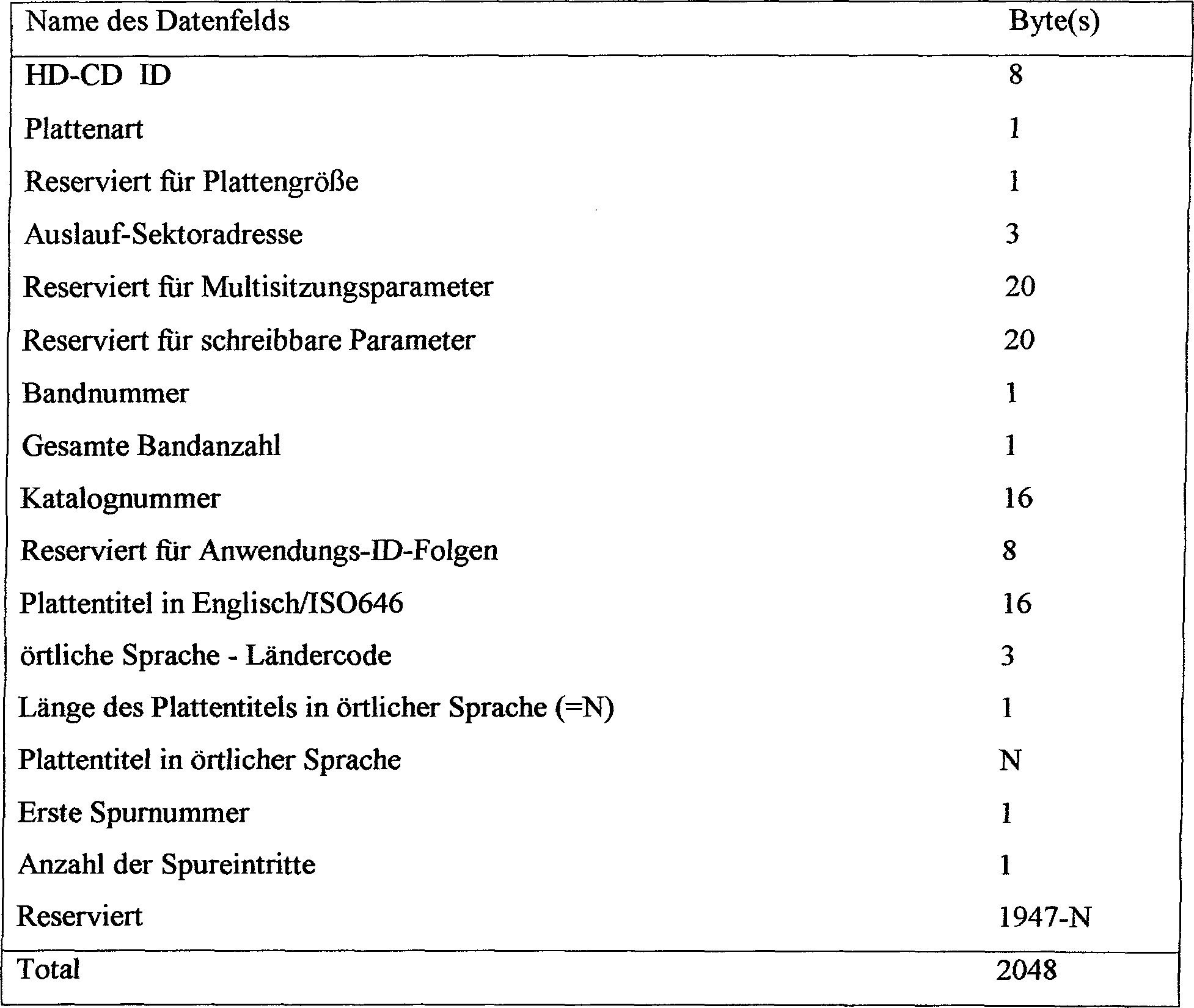
Die Datenfelder welche die Platteninformation identifizieren, werden ausführlicher wie folgt beschrieben:The data fields which are the disk information identify, become more detailed described as follows:

HD-CD ID: dieses Datenfeld, welches aus 8 Bytes besteht, enthält eine Zeichenfolge, welche die Datenstruktur identifiziert, die auf der Platte aufgezeichnet ist, einschließlich der Datenstruktur, die verwendet wird, die TOC-Information zu zeigen, die Datenstruktur, die verwendet wird, die Spurinformation zu zeigen, und die Datenstruktur eines Sektors. Wenn beispielsweise die Zeichenfolge "HD-CD001" ist, ist die Datenstruktur, welche auf der Platte aufgezeichnet ist, so, wie in 4 gezeigt ist, die Datenstruktur, die verwendet wird, die TOC-Information zu zeigen, so, wie in Tabelle 1 gezeigt ist, die Datenstruktur, die verwendet wird, die Spurinformation zu zeigen, so, wie in Tabelle 2 und 3 gezeigt ist, und die Datenstruktur der Sektoren von beispielsweise den Benutzerdatenspuren so, wie in Tabelle 4 gezeigt ist (was beschrieben wird). Unterschiedliche Datenstrukturen können durch die Zei chenfolge "HD-CD002", "HD-CD003", usw. identifiziert werden. Die spezielle Zeichnfolge, die in diesem Datenfeld aufgezeichnet ist, wird durch das Wiedergabegerät ermittelt, welches eine genaue Interpretation der wiedergegebenen Daten erlaubt, die in Einklang mit der ermittelten Datenstruktur stehen.HD-CD ID: this data field, which consists of 8 bytes, contains a character string that identifies the data structure that is recorded on the disk, including the data structure that is used to show the TOC information, the data structure that is used will show the track information and the data structure of a sector. For example, if the string is "HD-CD001", the data structure recorded on the disk is as in FIG 4 the data structure used to show the TOC information as shown in Table 1, the data structure used to show the track information as shown in Tables 2 and 3, and the data structure of the sectors from, for example, the user data tracks as shown in Table 4 (which will be described). Different data structures can be identified by the character string "HD-CD002", "HD-CD003", etc. The special character sequence that is recorded in this data field is determined by the reproducing device, which allows an exact interpretation of the reproduced data, which is in accordance with the determined data structure stand.

Plattenart: diese 1-Byte-Daten identifizieren die Plattenart, beispielsweise eine Nur-Lese-Platte, eine einmal beschreibbare, oft lesbare Platte (WORM) oder eine löschbare Platte (beispielsweise die optische beschreibbare Platte, die als Mini-Disc bekannt ist).Disk type: identify this 1-byte data the disk type, for example a read-only disk, once writable, often readable record (WORM) or an erasable Disk (for example, the optical recordable disk, which as Mini disc is known).

Reserviert für Plattengröße: dieses 1-Byte-Datenfeld wird dazu verwendet, die Größe der optischen Platte zu identifizieren. Beispielsweise kann ein Plattendurchmesser von 120 mm durch ein Byte identifiziert werden, dessen Wert gleich "1" ist, eine Platte, deren Durchmesser 80 mm beträgt, kann durch ein Byte identifiziert werden, dessen Wert gleich "2" ist, usw.. Zusätzlich oder als alternativ kann dieses Datenfeld dazu verwendet werden, die Speicherkapazität der Platte zu identifizieren.Reserved for disk size: this 1-byte data field is used to size the optical disc to identify. For example, a plate diameter of 120 mm can be identified by a byte whose value is "1", a plate whose diameter Is 80 mm, can be identified by a byte whose value is "2", etc. In addition or as an alternative this data field can be used to determine the storage capacity of the disk to identify.

Auslauf-Sektoradresse: dieses 3-Byte-Datenfeld identifiziert die Adresse des ersten Sektors im Auslaufbereich.Discontinued sector address: this 3-byte data field identifies the address of the first sector in the lead-out area.

Reserviert für Multisitzungsparameter und schreibbare Parameter: diese zwei Datenfelder, wobei jedes aus 20 Bytes gebildet ist, speichern Information, die besondere für löschbare Platten oder für WORM-Platten nützlich ist und hier nicht weiter beschrieben wird.Reserved for multi-session parameters and writable parameters: these two data fields, each consisting of 20 Bytes are formed to store information that is special for erasable Plates or for WORM plates useful and is not further described here.

Bandnummer: dieses 1-Byte-Datenfeld wird verwendet, wenn mehrere Platten eine Datensammlung für eine bestimmte Anwendung bilden. Wenn beispielsweise die Sammlung 2, 3, 4 usw. Platten aufweist, identifiziert dieses Datenfeld, welche eine von den Platten die vorliegende Platte ist.Band number: this 1-byte data field is used when several disks form a data collection for a specific application. For example, if the collection 2 . 3 . 4 etc. has disks, this data field identifies which one of the disks is the present disk.

Gesamte Bandanzahl: dieses 1-Byte-Datenfeld identifiziert die Gesamtzahl von Platten, welche die Sammlung bilden, in welcher die vorliegende Platte enthalten ist.Total number of bands: this 1-byte data field identifies the total number of plates that make up the collection, in which the present plate is contained.

Katalognummer: dieses 16-Byte-Datenfeld wird dazu verwendet, die Informationsart oder die Programmart zu identifizieren, welche auf der Platte aufgezeichnet ist. Diese Identifikation bildet die "Katalognummer" und wird als UPC/EAN/JAN-Code dargestellt, der zur Zeit verwendet wird, verschiedene Güter zu identifizieren.Catalog number: this 16-byte data field is used to specify the information type or the program type identify which is recorded on the disc. This identification forms the "catalog number" and is used as a UPC / EAN / JAN code shown, which is currently used to identify various goods.

Reserviert für Anwendungs-ID-Folgen: dieses 8-Byte-Datenfeld soll dazu dienen, die bestimmte Benutzeranwendung für diesen Plattenträger zu identifizieren. Zur Zeit wird dieses Datenfeld nicht verwendet.Reserved for application ID sequences: this 8-byte data field is designed to serve the specific user application For this plate carrier to identify. This data field is currently not used.

Plattentitel in englisch/ISO646: dieses 16-Byte-Datenfeld speichert den Titel der Platte in englischer Sprache, wie durch den ISO646-Standard gezeigt wird. Obwohl der aktuelle Titel der Platte in einer anderen Sprache sein kann, ist dessen englische Übersetzung oder eine entsprechende englische Identifikation dieses Titels in diesem Datenfeld aufgezeichnet. Bei anderen Ausführungsformen kann das Datenfeld eine geringere oder größere Anzahl von Bytes enthalten, um so englische Titel einer kleineren oder größeren Länge unterzubringen.Record title in English / ISO646: this 16-byte data field stores the title of the disk in English, as shown by the ISO646 standard. Although the current one The title of the record can be in another language is its English translation or a corresponding English identification of this title in recorded in this data field. In other embodiments, the data field a smaller or larger number of bytes included so as to give a smaller or English title to accommodate greater length.

örtlicher Sprach-Ländercode: dieses 3-Byte-Datenfeld ist dazu da, die aktuelle Sprache des Titels der Platte zu identifizieren. Wenn beispielsweise der aktuelle Titel der Platte in japanisch ist, zeichnet dieses Datenfeld die örtliche Ländersprache in japanisch auf. Wenn der Titel in französisch ist, zeichnet dieses Datenfeld die örtliche Ländersprache in französisch auf. Der Code, der in diesem Datenfeld aufgezeichnet ist, kann einen numerischen Wert zeigen, der einem bestimmten Land entspricht, oder alternativ kann dieses Datenfeld so sein, wie durch den ISO3166-Standard vorgeschrieben ist. Wenn nicht gewünscht wird, dieses Datenfeld zu nutzen, kann die Zeichnfolge, die hier aufgezeichnet ist, OxFFFFFF sein.local Language country code: this 3-byte data field is there for the current language of the title to identify the plate. For example, if the current title the plate is in Japanese, this data field draws the local one countries language in Japanese. If the title is in French, this will draw Data field the local countries language in French on. The code recorded in this data field can be a numeric Show value that corresponds to a specific country, or alternatively this data field can be as prescribed by the ISO3166 standard is. If not wanted is going to use this data field can use the string here is recorded to be OxFFFFFF.

Länge des Plattentitels in örtlicher Sprache: dieses 1-Byte-Datenfeld identifiziert die Anzahl von Bytes, die im Datenfeld für "Plattentitel in örtlicher Sprache" (was beschrieben wird) verwendet werden, um den Titel der Platte in der örtlichen Sprache zu zeigen. Wenn der Titel der aktuellen Platte nur in englischer Sprache aufgezeichnet ist, bleibt das Datenfeld "Plattentitel in örtlicher Sprache" leer und der numerische Wert dieses Datenfelds (Länge des Plattentitels in örtlicher Sprache" ist 0.length of the record title in local Language: this 1-byte data field identifies the number of bytes that in the data field for "Record titles in local Language "(what is described will) be used to record the title in the local To show language. If the title of the current record is only in English Language is recorded, the data field "Record title in local language" remains empty and the numerical Value of this data field (length of the record title in local Language "is 0.

Plattentitel in örtlicher Sprache: dieses N-Byte-Datenfeld zeigt den aktuellen Titel der Platte in der örtlichen Sprache. Man erwartet, dass unterschiedliche Sprachen unterschiedliche Standards annehmen werden, um Plattentitel darzustellen, wobei erwartet wird, dass diese örtlichen Sprachstandards als Daten verwendet werden, die in diesem Datenfeld aufgezeichnet sind. Man sieht, dass in vorteilhafter Weise die Anzahl von Bytes, die dieses Datenfeld bilden, variabel ist.Local language disc title: this N-byte data field shows the current title of the record in the local language. One expect, that different languages adopt different standards to represent record titles, with the expectation that these local Language standards are used as data in this data field are recorded. You can see that advantageously the number of bytes that make up this data field is variable.

Erste Spurnummer: dieses 1-Byte-Datenfeld identifiziert die Nummer der Spur, die die erste Spur bildet, welche die Benutzerinformation enthält. Wenn beispielsweise die TOC-Information in einer einzelnen Spur aufgezeichnet ist und wenn diese einzelne Spur als Spur 0 im Programmbereich identifiziert wird, ist die Nummer der Spur, welche die "erste Spurnummer" bildet, 1.First track number: this 1-byte data field identifies the number of the track that forms the first track, which contains the user information. For example, if the TOC information is recorded in a single track and if this single track is identified as track 0 in the program area the number of the track that forms the "first track number" is 1.

Anzahl der Spureintritte: dieses 1-Byte-Datenfeld identifiziert die Gesamtzahl der Benutzerspuren, die aufgezeichnet sind. Man sieht in vorteilhafter Weise, dass, wenn dieses Datenfeld ein einzelnes Byte enthält, eine Maximalzahl von 256 Benutzerdatenspuren, d. h., Spuren, welche Benutzerinformation enthalten, aufgezeichnet werden kann.Number of lane entries: this 1-byte data field identifies the total number of user tracks, that are recorded. You can see in an advantageous way that if this data field contains a single byte, a maximum of 256 User data traces, d. i.e., tracks that contain user information, can be recorded.

Die Daten, welche in den Spurinformationsdatenfeldern der TOC-Daten aufgezeichnet sind, die in Tabelle 1 gezeigt sind, werden nun in Verbindung mit der folgenden Tabelle 3 beschrieben:The data contained in the lane information data fields of the TOC data shown in Table 1 is recorded are now described in connection with the following Table 3:

Tabelle 3 Spurinformation

Figure 00230001
Table 3 Lane information
Figure 00230001

Die Information, die in allen Datenfeldern aufgezeichnet ist, welche die Spurinformation von Tabelle 3 bilden, wird nun ausführlicher beschrieben.The information in all data fields recorded, which form the track information of Table 3, will now be more detailed described.

Spurnummer: dieses 1-Byte-Datenfeld identifiziert die Nummer der Spur, welche durch diese Spurinformation gezeigt wird. Da ein Byte dazu verwendet wird, die Spurnummer zu identifizieren, sieht man, dass eine maximale Anzahl von 256 Benutzerdatenspuren aufgezeichnet werden kann. Natürlich wird eine einzelne Spurnummer dazu verwendet, eine entsprechende Spur zu identifizieren, und es werden nicht zwei Spuren auf dieser Platte durch die gleiche Spurnummer identifizier. Obwohl bevorzugt wird, dass die aufeinanderfolgenden Spuren sequentiell nummeriert sind, ist es auch vorteilhaft, dass, wenn gewünscht, jeder Spur eine Zufallsnummer zugeteilt werden kann und diese Spurnummer durch das Datenfeld "Spurnummer" identifiziert wird.Track number: this 1-byte data field identifies the number of the track, which by this track information will be shown. Since one byte is used to track the number identify, you can see that a maximum number of 256 user data tracks can be recorded. Naturally a single track number is used, a corresponding one Identify track and there will not be two tracks on this Identify plate by the same track number. Although preferred is that the successive tracks are numbered sequentially , it is also advantageous that, if desired, each track has a random number can be allocated and this track number is identified by the data field "track number".

ECC-Art: diese 1-Byte-Daten identifizieren den Fehlerkorrekturcode, der dazu verwendet wird, die Benutzerdaten, welche in dieser Spur aufgezeichnet sind, zu codieren. Beispielsweise kann die ECC-Art entweder der Langabstands-Fehlerkorrekturcode sein, der als L-Format bekannt ist, oder der Kurzabstands-Fehlerkorrekturcode, der als das S-Format bekannt ist. Der Unterschied zwischen dem L-Format und dem S-Format wird später beschrieben.ECC type: identify this 1-byte data the error correction code used to store the user data, which are recorded in this track. For example the ECC type can be either the long distance error correction code, which is known as the L format, or the short distance error correction code, which is known as the S format. The difference between the L format and the S format will be later described.

Geschwindigkeitseinstellung: diese 1-Byte-Daten identifizieren die Datenübertragungsrate, mit der Daten von dieser Spur wiederentwickelt werden. Wenn beispielsweise eine Referenzdatenübertragungsrate 1,4 Mbps beträgt, kann das Datenfeld "Geschwindigkeitseinstellung" einen Wert zeigen, der das 1x dieser Referenzrate oder das 2x der Referenzrate oder das 4x der Referenzrate oder das 6x der Referenzrate zeigt. 8 ist eine tabellarische Darstellung dieses Datenfelds "Geschwindigkeitseinstellung". Man sieht, dass in vorteilhafter Weise die Datenübertragungsrate nicht ein ganzzahliges Vielfaches der Referenzdaten-Übertragungsrate sein muss, wie durch den Wert "FF" dargestellt ist. Der Bytewert 0 für dieses Datenfeld zeigt, wie in 8 gezeigt ist, dass das Realzeitlesen von Daten nicht erforderlich ist. Man sieht, dass Computerdaten im Gegensatz zu beispielsweise Videodaten kein Realzeitlesen erfordern. Wenn folglich Computerdaten in der Spur aufgezeichnet sind, die durch das Datenfeld "Spurnummer" in Tabelle 3 identifiziert wird, wird der Wert des Datenfelds "Geschwindigkeitseinstellung" auf 0 eingestellt.Speed setting: this 1-byte data identifies the data transfer rate at which data from this track is redeveloped. For example, if a reference data transfer rate is 1.4 Mbps, the "Speed Setting" data field may show a value that shows 1x this reference rate or 2x the reference rate or 4x the reference rate or 6x the reference rate. 8th is a tabular representation of this data field "speed setting". It can be seen that the data transmission rate advantageously does not have to be an integer multiple of the reference data transmission rate, as represented by the value "FF". The byte value 0 for this data field shows how in 8th it is shown that the real-time reading of data is not required. It can be seen that, unlike video data, for example, computer data does not require real-time reading. Accordingly, when computer data is recorded in the track identified by the "track number" data field in Table 3, the value of the "speed setting" data field is set to 0.

Beginn und Ende von Sektoradressen (SA): diese 3-Byte-Datenfelder identifizieren die Adresse des Startsektors der Spur, die im Datenfeld "Spurnummer" identifiziert wird, und die Adresse des Endsektors dieser Spur. Da die Nummer von Sektoren, die in einer Spur enthalten sind, variabel ist, ist der Beginn und das Ende von Sektoradressen einer vorgegebenen Spur nicht fest. Folglich sind diese Datenfelder nützlich, wenn eine Hochgeschwindigkeits-Zugriffsoperation einer gewünschten Spur ausgeführt wird.Start and end of sector addresses (SA): these 3-byte data fields identify the address of the start sector the track that is identified in the "track number" data field, and the address of the end sector of this track. Because the number of sectors, which are contained in a track is variable, is the beginning and the end of sector addresses of a given track is not fixed. Consequently, these data fields are useful when a high speed access operation a desired one Track executed becomes.

Zeitcode bei Startpunkt:Time code at starting point:

dieses 4-Byte-Datenfeld identifiziert einen Zeitcode für den Startsektor in der Spur, die durch das Datenfeld "Sparnummer" identifiziert wird. Man sieht, dass, wenn die Benutzerinformation Videodaten zeigt, diese Videodaten mit herkömmlichen Zeitcodes aufgezeichnet sein können und der Startsektor der Spur, der diese Videodaten enthält, in diesem Datenfeld "Zeitcode beim Startpunkt" aufgezeichnet ist. Wenn Zeitcodes nicht mit der Benutzerinformation aufgezeichnet sind, kann dieses Datenfeld leer bleiben oder es kann mit keinen Daten versehen sein, beispielsweise dem Zeichencode 0.this 4 byte data field identifies a time code for the start sector in the track, which is identified by the data field "economy number". It can be seen that if the user information shows video data, this video data can be recorded with conventional time codes and the start sector of the track that this Contains video data, "Time code at starting point" is recorded in this data field. If time codes are not recorded with the user information, this data field can remain empty or it can be provided with no data, for example the character code 0 ,

Wiedergabezeit: diese 4-Byte-Daten zeigen die Gesamtwiedergabezeit für die Programminformation, welche in der Spur aufgezeichnet ist, die durch das Datenfeld "Sparnummer" identifiziert wird. Wenn beispielsweise die Benutzerinformation in dieser Spur ein Audioprogramm ist, kann die Wiedergabezeit für diese Spur in der Größenordnung von ungefähr 10 Minuten sein. Wenn die Benutzerinformation komprimierte Videodaten enthält, kann die Wiedergabezeit 2 oder 3 oder bis zu 15 Minuten sein.Playback time: this 4 byte data shows the total playback time for the program information recorded in the track identified by the data field "economy number". For example, if the user information in that track is an audio program, the playback time for that track may be on the order of about 10 minutes. If the user information contains compressed video data, the playback time may 2 or 3 or be up to 15 minutes.

Herstellungsdatum und Zeit: dieses 7-Byte-Datenfeld identifiziert das Datum und die Zeit der Bildung der Masterplatte, von welcher diese optische Platte hergestellt wurde. 9 ist eine tabellarische Darstellung dieses Datenfelds. Wenn gewünscht, kann dieses Datenfeld durch 0-Daten ersetzt werden, die durch den Zeichencode 0 dargestellt werden.Date of manufacture and time: this 7-byte data field identifies the date and time of formation of the master disk from which this optical disk was manufactured. 9 is a tabular representation of this data field. If desired, this data field can be replaced by 0 data, which is the character code 0 being represented.

Reserviert für Anwendungs-ID-Folgen: dieses 8-Byte-Datenfeld ist dazu da, Information zu speichern, die für die besondere Anwendung repräsentativ ist, für welche die Datenaufzeichnung in der Spur, die durch das Datenfeld "Sparnummer" identifiziert wird, verwendet werden soll. Dies ist etwas unterschiedlich gegenüber dem Datenfeld "Anwendungs-ID" in Tabelle 2, da das Datenfeld der Tabelle 2 dazu dienen soll, die Anwendungsart oder Verwendung zu identifizieren, die für die gesamte Platte beabsichtigt ist, während das Datenfeld von Tabelle 3 "Anwendungs-ID" lediglich die Art oder Verwendung der Daten identifiziert, welche auf einer speziellen Spur auf dieser Platte aufgezeichnet sind.Reserved for application ID sequences: this 8-byte data field is there to store information that is special for that Application representative is for which is the data record in the track identified by the data field "savings number", should be used. This is slightly different from that Data field "Application ID" in table 2, because the data field in Table 2 is intended to serve the type of application or identify use that is intended for the entire plate is while the data field of Table 3 "Application ID" only the type or use of the data identified on a particular Track are recorded on this disc.

Betrachtet man nun 10, so ist dort eine bevorzugte Ausführungsform der Datenstruktur eines Sektors der Benutzerinformation gezeigt. Die TOC-Information ist ebenfalls in Sektoren aufgezeichnet, und die Struktur eines solchen TOC-Sektors ist ähnlich. Die folgende Tabelle 4 identifiziert die Datenfelder der Sektoren, die in 10 gezeigt sind:Now consider it 10 , there is shown a preferred embodiment of the data structure of a sector of the user information. The TOC information is also recorded in sectors and the structure of such a TOC sector is similar. The following Table 4 identifies the data fields of the sectors that are in 10 are shown:

Tabelle 4 Sektoraufbau

Figure 00250001
Table 4 Sector structure
Figure 00250001

Man sieht, dass ein Sektor aus einem Sektordatenkopf besteht, der 24 Bytes enthält, der bei einer Ausführungsform angeordnet sind, wie in 10A gezeigt ist, dem 2048 Bytes an Benutzerdaten, 4 Bytes eines Fehlerermittlungscodes (DEDC) und 12 Bytes folgen, die reserviert sind. Vorzugsweise bilden eine Anzahl von Sektoren einen "Cluster", wobei als ein Beispiel ein Cluster aus 8 Sektoren oder 16 Sektoren besteht, wie durch das bevorzugte Format festgelegt werden kann.It can be seen that a sector consists of a sector header containing 24 bytes arranged in one embodiment, as in FIG 10A shown, followed by 2048 bytes of user data, 4 bytes of an error detection code (DEDC) and 12 bytes that are reserved. Preferably, a number of sectors form a "cluster", as an example a cluster consisting of 8 sectors or 16 sectors, as can be determined by the preferred format.

Die verschiedenen Datenfelder, welche den Sektor bilden, der in 10A gezeigt ist, werden nun ausführlicher erläutert.The various data fields that form the sector that in 10A is now explained in more detail.

Sektorsynchronisation:Sector synchronization:

Dieses 4-Byte-Datenfeld besteht aus einem vorher festgelegten Bitmuster, welches schnell ermittelt und welches einzig und unterscheidend gegenüber dem Datenmuster ist, welches in jedem anderen Datenfeld eines Sektors enthalten ist. Die genaue Ermittlung des Synchronisationsmusters kann durch Abtastungsfehler bestätigt werden, die von der Information, welche vom Sektor reproduziert wird, interpretiert werden. Wenn eine große Anzahl von Fehlern laufend ermittelt wird, kann sicher angenommen werden, dass das Synchronisationsmuster nicht genau abgetastet wurde. Alternativ und bevorzugt kann der Demodulator, der dazu verwendet wird, 16-Symbole in 8-Bit-Bytes umzusetzen (oder allgemeiner um ein m-Bit-Symbol in ein n-Bit-Byte umzusetzen) geeignete Umsetzungstabellen aufweisen, welche nicht betriebsfähig sind, das Synchronisationsmuster in ein Byte umzusetzen. Es wird angenommen, dass das Synchronisationsmuster vorhanden ist, wenn es dem Demodulator nicht möglich ist, ein n-Bit-Byte zu finden, welches einem empfangenen m-Bit-Symbol entspricht.This 4-byte data field consists of a predefined bit pattern, which is quickly determined and which is unique and distinctive from the data pattern contained in every other data field of a sector. The exact determination of the synchronization pattern can be confirmed by sampling errors which are interpreted by the information which is reproduced by the sector. If a large number of errors are continuously detected, it can safely be assumed that the synchronization pattern has not been scanned exactly. Alternatively and preferably, the demodulator used to convert 16 symbols to 8-bit bytes (or more generally to convert an m-bit symbol to an n-bit byte) may have suitable conversion tables that are not operational, convert the synchronization pattern into a byte. It is assumed that the synchronization pattern is present if the demodulator is unable to find an n-bit byte that corresponds to a received m-bit symbol.

Zyklischer Redundanzcode (CRC): dieses 2-Byte-Datenfeld wird von den Subcodedaten, den Clusterpositionsdaten und der Sektoradresse und den Modusdaten, welche im Sektordatenkopf enthalten sind, hergeleitet. Diese CRC-Daten werden dazu verwendet, Fehler zu korrigieren, die in diesen Datenfeldern vorhanden sein können.Cyclic redundancy code (CRC): this 2-byte data field is made up of the subcode data, the cluster position data and the sector address and mode data stored in the sector header are included. This CRC data is used to Correct errors that exist in these data fields can.

Subcode: dieses 5-Byte-Datenfeld wird später beschrieben.Subcode: this 5-byte data field will later described.

Clusterposition: dieses 1-Byte-Datenfeld identifiziert die spezielle Ordnung im Cluster, in welchem dieser Sektor angeordnet ist. Wenn beispielsweise der Cluster aus 8 Sektoren gebildet ist, identifiziert dieses Datenfeld den speziellen Sektor als ersten, zweiten, dritten usw. Sektor im Cluster.Cluster position: this 1-byte data field identifies the particular order in the cluster in which of these Sector is arranged. For example, if the cluster consists of 8 sectors this data field identifies the special sector as the first, second, third, etc. sector in the cluster.

Adresse: dieses 3-Byte-Datenfeld bildet die eigene Adresse für diesen Sektor. Da die Adresse als 3-Bytes dargestellt wird, kann eine maximale Anzahl von 64 K Sektoren theo retisch aufgezeichnet sein. 47 zeigen die Sektoradressen unterschiedlicher Benutzerdatenspuren.Address: this 3-byte data field forms the own address for this sector. Since the address is represented as 3 bytes, a maximum number of 64 K sectors can be theoretically recorded. 4 - 7 show the sector addresses of different user data tracks.

Modus und Subdatenkopf: diese Datenfelder werden üblicherweise bei CD-ROMs verwendet, und die Daten, die hier gezeigt werden, sind die gleichen wie die, die herkömmlicherweise bei diesen CD-ROMs verwendet werden.Mode and sub-header: these data fields are common used in CD-ROMs, and the data shown here is the same as the traditionally can be used with these CD-ROMs.

Benutzerdaten: 2048 Bytes an Information sind in dem Benutzerdatenfeld aufgezeichnet. Beispielsweise können Computerdaten, komprimierte Videodaten, Audiodaten und dgl. aufgezeichnet sein. Wenn Videodaten aufgezeichnet sind, kann der MPEG-Standard verwendet werden, um diese Daten zu komprimieren, wie im Standard ISO1381-1 beschrieben ist.User data: 2048 bytes of information are recorded in the user data field. For example, computer data, compressed video data, audio data and the like may be recorded. When video data is recorded, the MPEG standard can be used to compress this data, as in the ISO1381-1 standard is described.

Fehlerermittlungscode: diese 4-Byte-Daten sind der zyklische Code, der durch den EDC-Addierer 127 hinzugefügt wird (1) und verwendet wird, die Ermittlung eines nichtkorrigierbaren Fehlers im Sektor zu ermöglichen.Error detection code: this 4-byte data is the cyclic code that is passed through the EDC adder 127 will be added ( 1 ) and is used to enable the determination of an uncorrectable error in the sector.

10B zeigt schematisch eine andere Ausführungsform eines Sektordatenkopfs, wobei dieser 20 Bytes enthält. Die Datenfelder des 20-Byte-Sektordatenkopfs von 10B sind ähnlich den Datenfeldern des Sektordatenkopfs, der in 10A gezeigt ist, und, um eine unnötige doppelte Erläuterung zu vermeiden, werden diese nicht weiter beschrieben. 10B Figure 3 schematically shows another embodiment of a sector header, which contains 20 bytes. The data fields of the 20 byte sector header from 10B are similar to the data fields in the sector header shown in 10A is shown, and to avoid unnecessary duplicate explanation, these are not further described.

Es wird nun das Subcodedatenfeld ausführlich in Verbindung mit 11A11E erläutert. Man sieht, dass in vorteilhafter Weise das Subcodedatenfeld aus zwei Bereichen besteht: einem 1-Byte-Adressbereich und einem 4-Byte-Datenbereich. Der Wert des Adressbereich dient dazu, die Art von Daten zu identifizieren, welche im Datenbereich aufgezeichnet sind. Wenn beispielsweise und wie in 11A gezeigt ist der Wert des Adressbereichs gleich 0 ist, sind Null-Daten im Datenbereich aufgezeichnet.The subcode data field is now extensively linked to 11A - 11E explained. It can be seen that the subcode data field advantageously consists of two areas: a 1-byte address area and a 4-byte data area. The value of the address area is used to identify the type of data that is recorded in the data area. If, for example, and as in 11A shown the value of the address area is 0, zero data is recorded in the data area.

Wenn der Wert des Adressbereichs gleich 1 ist, wie in 11B gezeigt ist, ist der Datenbereich mit der folgenden 1-Byte-Information versehen:If the value of the address range is 1, as in 11B is shown, the data area is provided with the following 1-byte information:

Spurnummer: diese Daten identifizieren die Nummer der Spur, in welchem der Sektor, der diesen Subcode enthält, aufgezeichnet ist.Track number: identify this data the number of the track in which the sector containing this subcode is recorded is.

Copyright: dieses Byte zeigt die Struktur, die in 12 gezeigt ist, wobei ein "1"-Bit zeigt, dass das Kopieren der verknüpften Benutzerdaten verboten ist, und ein Bit "0" zeigt, dass das Kopieren der verknüpften Daten erlaubt ist. Die Bitpositionen des Copyright-Bytes identifizieren die Art von Benutzerdaten, für welche das Kopieren wahlweise untersagt oder erlaubt ist. Wie in 12 gezeigt ist, sind die identifizierten Benutzerdaten analoge Videodaten, analoge Audiodaten, digitale Videodaten, digitale Audiodaten und dgl.. Wenn beispielsweise die Benutzerdaten in diesem Sektor digitale Videodaten sind und wenn das Ko pieren dieser digitalen Videodaten untersagt ist, kann das Copyrightbyte so aussehen: "00100000" .Copyright: this byte shows the structure contained in 12 with a "1" bit showing that copying the linked user data is prohibited and a bit "0" showing that copying the linked data is allowed. The bit positions of the copyright byte identify the type of user data for which copying is either prohibited or permitted. As in 12 is shown, the identified user data are analog video data, analog audio data, digital video data, digital audio data and the like. If, for example, the user data in this sector is digital video data and if copying of these digital video data is prohibited, the copyright byte can look like this: " 00100000 ".

Anwendungs-ID: diese zeigt die spezielle Anwendung, die für die Benutzerdaten beabsichtigt ist, die in diesem Sektor aufgezeichnet sind. Beispielsweise typischer Anwendungen sind in 13 gezeigt, beispielsweise Computertext, Video, Video/Audio, usw.. Wenn keine Daten in diesem Sektor aufgezeichnet sind, kann das Anwendungs-ID-Byte als Zeichen 0 dargestellt sein.Application ID: this shows the specific application that is intended for the user data recorded in this sector. Examples of typical applications are in 13 shown, for example computer text, video, video / audio, etc. If no data is recorded in this sector, the application ID byte can be used as a character 0 be shown.

ECC-Art: diese Daten zeigen, ob die Benutzerdaten beispielsweise im L-Format oder im S-Format ECC-codiert sind, wie in 16 gezeigt ist. Andere Arten von ECC-Codes können durch andere Werte dieses ECC-Bytes dargestellt werden.ECC type: this data shows whether the user data is, for example, L-format or S-format ECC-coded, as in 16 is shown. Other types of ECC codes can be represented by other values of this ECC byte.

Wenn der Wert der Subcodeadresse gleich 2 ist, wie in 11C gezeigt ist, zeigt der Datenbereich den Zeitcode. Das heißt, wenn die Benutzerdaten, die in diesem Sektor aufgezeichnet sind, über der Zeit variabel sind, wie dies der Fall sein würde, wenn die Daten Videodaten sind, zeigen die Zeitcodedaten, welche im Subcodedatenfeld aufgezeichnet sind, die Zeitinformation, mit der die Benutzerdaten aufgezeichnet sind. Ein Beispiel dieser Zeitcodedaten ist in 14 dargestellt. Man sieht, dass in vorteilhafter Weise die 2-Zeichen-BCD-Bits dazu verwendet werden, die Stunde, Minute, die Sekunde und den Rahmen zu zeigen, bei denen die Benutzerdaten in diesem Sektor aufgezeichnet sind.If the value of the subcode address is 2, as in 11C is shown, the data area shows the time code. That is, if the user data recorded in this sector is above the time va As is the case if the data is video data, the time code data recorded in the subcode data field shows the time information with which the user data is recorded. An example of this time code data is in 14 shown. It can be seen that the 2-character BCD bits are advantageously used to show the hour, minute, second and frame at which the user data is recorded in this sector.

Wenn der Wert des Adressbereichs gleich 3 ist, wie in 11D gezeigt ist, zeigt der Datenbereich des Subcodedatenfelds den Abstand vom Sektor, in welchem diese Subcodedatenfeld aufgezeichnet ist, zum ersten Sektor, in welchem ein unmittelbar vorhergehendes I-komprimiertes Videobild aufgezeichnet ist, und außerdem den Abstand von diesem Sektor zum ersten Sektor, in welchem das nachfolgende I-komprimierte Videobild aufgezeichnet ist. Der Fachmann wird erkennen, dass Videodaten, wenn diese gemäss dem MPEG-Standard komprimiert sind, ein intra-rahmen-codiertes Videobild bilden können, was üblicherweise als I-Bild bekannt ist, ein vorhersage-codiertes Videobild, welches als P-Bild üblicherweise bekannt ist, und ein bi-direktional-vorhersage-codiertes Videobild, welches üblicherweise als B-Bild bekannt ist. Der Datenbereich des Subcodedatenfelds, dessen Adressbereich den Wert 3 hat, zeigt somit die Abstände zwischen diesem Sektor und dem Anfang des unmittelbar vorhergehenden und des unmittelbar nachfolgenden I-Bilds.If the value of the address range is 3, as in 11D the data area of the subcode data field shows the distance from the sector in which this subcode data field is recorded to the first sector in which an immediately preceding I-compressed video image is recorded and also the distance from this sector to the first sector in which the subsequent I-compressed video image is recorded. Those skilled in the art will recognize that video data, when compressed according to the MPEG standard, can form an intra-frame coded video picture, which is commonly known as an I-picture, a predictively coded video picture, commonly known as a P-picture and a bi-directional predictive-encoded video image commonly known as a B-image. The data area of the subcode data field, the address area of which has the value 3, thus shows the distances between this sector and the beginning of the immediately preceding and the immediately following I-picture.

Wenn der Wert des Adressbereichs gleich 4 ist, wie in 11E gezeigt ist, umfasst der Datenbereich ein 1-Byte-Bild, welches zeigt, ob das Videobild, welches in diesem Sektor aufgezeichnet ist, ein I-, P- oder B-Bild ist (siehe 15), und temporäre 2-Byte-Referenzdaten, welche die Lage in der ursprünglichen Bildanzeigesequenz des speziellen Bilds zeigen, welches in diesem Sektor aufgezeichnet ist. Diese temporären Referenzdaten sind während einer Wiedergabeoperation hilfreich, da, wie der Fachmann erkennt, die Lage von komprimierten B-Bilddaten in der MPEG-Codesequenz ziemlich verschieden gegenüber der tatsächlichen Lage dieses Bilds sein kann, wenn das P-Bild schließlich angezeigt wird.If the value of the address range is 4, as in 11E the data area comprises a 1-byte picture, which shows whether the video picture recorded in this sector is an I, P or B picture (see 15 ), and temporary 2-byte reference data showing the location in the original image display sequence of the particular image recorded in this sector. This temporary reference data is helpful during a playback operation because, as those skilled in the art will recognize, the location of compressed B-frame data in the MPEG code sequence may be quite different from the actual location of that frame when the P-frame is finally displayed.

Das ECC-Format, welches vorzugsweise bei der vorliegenden Erfindung verwendet wird, ist das L-Format. Eine schematische Darstellung eines codierten "Datenrahmens" ist in 17 gezeigt. Der ECC-"Rahmen" wird hier als C1-Codewort bezeichnet, und dieses Wort, wenn es aufgezeichnet ist, besteht aus einem Synchronisationsmuster, dem 136 Datensymbole folgen. Der Ausdruck "Symbol" wird bevorzugt zu "Byte" verwendet, da, wie beschrieben wird, das aufgezeichnete "Symbol" aus 16 Bits besteht (als Kanalbits bekannt), während ein Byte üblicherweise so verstanden wird, dass es lediglich aus 8 Bits besteht. Man erkennt jedoch in vorteilhafter Weise, dass das C1-Codewort vor der Umsetzung von 8-Bit-Bytes auf 16-Bit-Symbole, d. h., vor der Modulation des C1-Codeworts trotzdem aus dem Aufbau besteht, der in 17 gezeigt ist, wo verstanden wird, dass die gezeigten Symbole tatsächlich Bytes sind.The ECC format, which is preferably used in the present invention, is the L format. A schematic representation of a coded "data frame" is in 17 shown. The ECC "frame" is referred to herein as the C1 code word, and this word, when recorded, consists of a synchronization pattern followed by 136 data symbols. The term "symbol" is preferably used to refer to "byte" because, as will be described, the recorded "symbol" consists of 16 bits (known as channel bits), while a byte is usually understood to consist of only 8 bits. However, it can be seen in an advantageous manner that the C1 code word before the conversion from 8-bit bytes to 16-bit symbols, that is to say before the modulation of the C1 code word, nevertheless consists of the structure shown in 17 is shown where it is understood that the symbols shown are actually bytes.

Die Art und Weise, mit der die C1-Codewortstruktur erzeugt wird, wird nun kurz beschrieben. 116 Datenbytes oder Symbole, bekannt als C2-Wort, werden beispielsweise zum ECC-Codierer geliefert, der aus dem Speicher 131 und der ECC-Schaltng 132 von 1 besteht. Ein C2-Halteabschnitt wird dem C2-Wort hinzugefügt, der vorzugsweise zwischen zwei Gruppen von 58 Symbolen eingefügt wird, und ein C1-Halteabschnitt wird dem Ende der resultierenden 128 Symbole hinzugefügt. Ein Haltesabschnitt reserviert lediglich eine Stelle im Datenstrom, in den Paritätsdaten nachfolgend eingefügt werden. Somit kann man sich vorstellen, dass ein vorläufiges C1-Wort aus einer Gruppe von 58 Datensymbolen gebildet ist, denen ein C2-Halteabschnitt folgt, dem eine Gruppe von 58 Datensymbolen folgt, denen ein C1-Halteabschnitt folgt. Dann werden C1-Paritätssymbole durch beispielsweise die Modulo-2-Addition erzeugt. Vorzugsweise wird ein Datensymbol in einem vorläufigen C1-Wort mit einem Datensymbol, welches im nächsten (oder zweiten) vorläufigen C1-Wort enthalten ist, modulo-2-kombiniert. Wenn gewünscht können weitere Kombinationen mit einem Datensymbol ausgeführt werden, welches im drittfolgenden vorläufigen C1-Wort enthalten ist, usw., um ein C2-Paritätssymbol zu erzeugen. Das nächste C2-Paritätssymbol wird durch eine ähnliche Kombination des nächsten Datensymbols in diesem ersten vorläufigen C1-Wort mit entsprechenden Datensymbolen in den anschließend nachfolgenden vorläufigen C1-Wörtern erzeugt. Auf diese Weise werden C2-Paritätssymbole erzeugt, wobei eine vorher festgelegte Anzahl von Datensymbolen der gleichen vorher festgelegten Anzahl von aufeinanderfolgen den vorläufigen C1-Wörtern kombiniert werden. Das heißt, wenn das C2-Paritätssymbol durch Modulo-2-Kombinieren von zwei Datenwörtern erzeugt wird, wird anschließend ein Datenwort des ersten vorläufigen C1-Worts mit einem Datensymbol in der nächsten Symbolposition des nachfolgenden vorläufigen C1-Worts modulo-2-kombiniert. Wenn das C2-Paritätssymbol durch Kombinieren von 3 Datensymbolen erzeugt wird, werden ein Datensymbol in den aufeinanderfolgenden Symbolpositionen von jedem der 3 aufeinanderfolgenden vorläufigen C1-Wörtern kombiniert, um das C2-Paritätssymbol zu erzeugen. Wenn das C2-Paritätssymbol durch Kombination von 4 Datensymbolen erzeugt wird, wird dann ein Datensymbol in aufeinanderfolgenden Symbolpositionen von jedem von 4 aufeinanderfolgenden vorläufigen C1-Wörtern kombiniert.The manner in which the C1 code word structure is generated will now be briefly described. 116 data bytes or symbols, known as C2 word, are supplied to the ECC encoder, for example, which comes from memory 131 and the ECC circuit 132 of 1 consists. A C2 hold section is added to the C2 word, which is preferably inserted between two groups of 58 symbols, and a C1 hold section is added to the end of the resulting 128 symbols. A holding section only reserves a place in the data stream in which parity data are subsequently inserted. Thus, one can imagine that a preliminary C1 word is formed from a group of 58 data symbols followed by a C2 hold section followed by a group of 58 data symbols followed by a C1 hold section. Then C1 parity symbols are generated by, for example, modulo 2 addition. A data symbol in a provisional C1 word is preferably combined in a modulo-2 manner with a data symbol which is contained in the next (or second) provisional C1 word. If desired, further combinations can be made with a data symbol contained in the third provisional C1 word, etc., to produce a C2 parity symbol. The next C2 parity symbol is generated by a similar combination of the next data symbol in this first provisional C1 word with corresponding data symbols in the subsequent provisional C1 words. In this way, C2 parity symbols are generated, combining a predetermined number of data symbols of the same predetermined number of consecutive C1 preliminary words. That is, if the C2 parity symbol is generated by modulo-2 combining two data words, then a data word of the first preliminary C1 word is modulo-2 combined with a data symbol in the next symbol position of the subsequent preliminary C1 word. When the C2 parity symbol is generated by combining 3 data symbols, a data symbol in the consecutive symbol positions of each of the 3 consecutive preliminary C1 words is combined to generate the C2 parity symbol. If the C2 parity symbol is generated by combining 4 data symbols, then a data symbol is combined in consecutive symbol positions from each of 4 consecutive preliminary C1 words.

Als bevorzugtes Merkmal dieser ECC-Codierung besetzen die Datensymbole, die kombiniert sind, aufeinanderfolgende Positionen in den entsprechenden vorläufigen C1-Wörtern. Das heißt, wenn das Datensymbol im ersten vorläufigen C1-Wort das n. Datensymbol ist, ist das Datensymbol im zweiten vorläufigen C1-Wort das (n + 1)-Datensymbol, und das Datensymbol im dritten vorläufigen C1-wort ist das (n + 2)-Datensymbol usw..As a preferred feature of this ECC coding consecutively occupy the data symbols that are combined Positions in the corresponding preliminary C1 words. This means, if the data symbol in the first provisional C1 word is the nth data symbol the data symbol in the second provisional C1 word is the (n + 1) data symbol, and the data symbol in the third provisional C1 word is (n + 2) data symbol etc.

Wenn 12 C2-Paritätssymbole in der gerade beschriebenen Weise erzeugt werden, werden diese 12 C2-Paritätssymbole in den C2-Halteabschnitt dieses ersten vorläufigen C1-Worts eingefügt, womit somit ein vorbereitendes C1-Wort gebildet wird. Dann werden 8 C1-Paritätssymbole durch die herkömmliche Paritätssymbolerzeugung als Antwort auf die Daten und die Paritätssymbole erzeugt, welche in diesem vorbereitenden C1-Wort enthalten sind. Die erzeugten C1-Paritätssymbole werden in den C1-Haltesbschnitt eingefügt, um somit das C1-Codewort zu bilden.If 12 C2 parity symbols in the just described These 12 C2 parity symbols are generated in the C2 hold section this first preliminary C1 word inserted, with what thus a preparatory C1 word is formed. Then 8 C1 parity symbols through the conventional Parity symbol generation in response to the data and parity symbols generated in this preparatory C1 word are included. The C1 parity symbols generated are inserted into the C1 hold section to include the C1 code word to build.

Im C1-Codewort, welches in 17 gezeigt ist, werden die C2-Paritätssymbole zwischen zwei Gruppen von Datensymbolen eingefügt. Alternativ können die C2-Paritätssymbole am Ende der 116 Datensymbole angeordnet sein, d. h., am Ende des C2-Worts. Eine vorher eingerichtete Anzahl von C1-Codewörtern, die den Aufbau haben, der in 17 gezeigt ist, bilden die Langabstands-Fehlerkorrektur-Codierdaten. Das heißt, eine vorher eingerichtete Anzahl von C1-Codewörtern werden als L-Format-ECC-codierte Daten verwendet, die den Aufbau haben, der in 18 gezeigt ist. Wie gezeigt ist, werden 128 C1-Codewörter verwendet, d. h., i = 0, 1 ... 127. Jedes C1-Codewort besteht aus einem Synchronisationscode oder Muster, auf welches 136 Symbole S0, S1, ... Sj ... S135 folgt, wobei j = 0, 1 . .. 135. Die in 18 gezeigten Kreise zeigen die Art und Weise, mit der die C2-Pairätssymbole erzeugt werden. Wie oben beschrieben wurde, werden die C2-Paritätssymbole für das C10-Codewort als Antwort auf die Datensymbole erzeugt, die in den Codewörtern C10, C11, ... C1r enthalten sind, wobei r die Anzahl von Datensymbolen zeigt und die kombiniert werden, um das Paritätssymbol zu erzeugen. Aus 17 und 18 erkennt man, dass die Symbole S0-S127 Daten und C2-Paritätssymbole bilden, und die Symbole S128-S135 C1-Paritätssymbole bilden. Man sieht, dass in vorteilhafter Weise, da 12 C2-Paritätssymbole in einem C1-Codewort aufgezeichnet sind, bis zu 12 Datensymbole korrigiert werden können. Da diese 12 Datensymbole in 12 aufeinanderfolgenden C1-Codewörtern enthalten sind, kann ein Burstfehler von zwölf C1-Codewörtern korrigiert werden, was einen korrigierbaren Fehler von bis zu 12 × 136 = 1632 Symbolen ergibt.In the C1 code word, which in 17 is shown, the C2 parity symbols are inserted between two groups of data symbols. Alternatively, the C2 parity symbols can be arranged at the end of the 116 data symbols, ie at the end of the C2 word. A pre-established number of C1 code words that have the structure described in 17 is shown, form the long distance error correction coding data. That is, a predetermined number of C1 code words are used as L-format ECC encoded data which have the structure shown in 18 is shown. As shown, 128 C1 code words are used, ie i = 0, 1 ... 127. Each C1 code word consists of a synchronization code or pattern on which 136 symbols S 0 , S 1 , ... S j . .. S 135 follows, where j = 0, 1. .. 135. The in 18 the circles shown show the way in which the C2 pair symbols are generated. As described above, the C2 parity symbols for the C1 0 code word are generated in response to the data symbols contained in the code words C1 0 , C1 1 , ... C1 r , where r shows the number of data symbols and the can be combined to create the parity symbol. Out 17 and 18 it can be seen that the symbols S 0 -S 127 form data and C2 parity symbols, and the symbols S 128 -S 135 form C1 parity symbols. It can be seen that, since 12 C2 parity symbols are recorded in a C1 code word, up to 12 data symbols can be corrected in an advantageous manner. Since these 12 data symbols are contained in 12 consecutive C1 code words, a burst error of twelve C1 code words can be corrected, which results in a correctable error of up to 12 × 136 = 1632 symbols.

Ein Beispiel der S-Format-ECC-Codierung ist schematisch in 19 gezeigt. Bei dem S-Format werden die zwölf C2-Paritätssymbole in zwei Gruppen von jeweils sechs C2-Paritätssymbolen unterteilt, wobei jeder eine Gruppe von sechs C2-Paritätssymbolen 58 Datensymbole und der anderen Gruppe von sechs C2-Symbolen die nächsten 58 Datensymbole hinzugefügt werden. Somit werden bevorzugt zum Erzeugen der C2-Paritätssymbole von Datensymbolen, welche in 128 C1-Codewärtern enthalten sind, die C2-Paritätssymbole im S-Format von aufeinanderfolgenden Datensymbolen erzeugt, welche in 64 C1-Codewörtern enthalten sind, die die schematische Darstellung haben, die in 19 gezeigt ist. Während das L-Format die Verwendung von C2-Paritätsymbolen erlaubt, um Fehler in zwölf C1-Codewörtern zu korrigieren, unterstützt das S-Format die C2-Paritätskorrektur von bis zu sechs C1-Codewörtern. Daher erlaubt das S-Format die Korrektur eines Burstfehlers von 6 × 136 = 816 Symbolen.An example of the S-format ECC coding is shown schematically in 19 shown. In the S format, the twelve C2 parity symbols are divided into two groups of six C2 parity symbols each, each a group of six C2 parity symbols 58 Data symbols and the other group of six C2 symbols the next 58 data symbols are added. Thus, to generate the C2 parity symbols from data symbols contained in 128 C1 code values, the C2 parity symbols in S format are generated from successive data symbols contained in 64 C1 code words having the schematic representation that in 19 is shown. While the L format allows the use of C2 parity symbols to correct errors in twelve C1 code words, the S format supports C2 parity correction of up to six C1 code words. Therefore the S format allows the correction of a burst error of 6 × 136 = 816 symbols.

Verglichen mit dem ECC-Format, welches beispielsweise bei CD-ROMs derart verwendet wird, welches vorher vorgeschlagen wurde, erlauben die Verwendung des L-Formats oder des S-Formats gemäß der vorliegenden Erfindung eine Reduktion der Redundanz von ungefähr 25% gegenüber den CD-ROMs des Standes der Technik auf ungefähr 15% bei der vorliegenden Erfindung.Compared to the ECC format, which is used for example in CD-ROMs, which previously has been proposed to allow the use of the L format or of the S format according to the present Invention a reduction in redundancy of approximately 25% over that Prior art CD-ROMs to about 15% in the present Invention.

Ein Sektor, der aus ECC-codierten Daten im L-Format oder im S-Format gebildet ist, ist in 21 gezeigt, wobei der Sektor einen Sektordatenkopf aufweist, der aus 24 Symbolen gebildet ist und der außerdem aus 18 C1-Codewörtern besteht, wobei jedes C1-Codewort den Aufbau hat, der in 17 gezeigt ist. Das letzte C1-Codewort, welches im Sektor enthalten ist, umfasst vier Ermittlungs-Codesymbole und zwölf Symbole, die für die zukünftige Verwendung reserviert sind. Der Sektordatenkopf zeigt den Aufbau, der in 10 gezeigt ist. Trotzdem können Fehler, die im Sektordatenkopf vorhanden sein können, allgemein unter Verwendung von lediglich den C1-Paritätssymbolen korrigiert werden, die für dieses C1-Codewort erzeugt werden.A sector which is formed from ECC-coded data in L format or in S format is shown in 21 shown, the sector having a sector header which is formed from 24 symbols and which also consists of 18 C1 code words, each C1 code word having the structure shown in 17 is shown. The last C1 code word contained in the sector comprises four detection code symbols and twelve symbols reserved for future use. The sector header shows the structure that in 10 is shown. Nevertheless, errors that may exist in the sector header can generally be corrected using only the C1 parity symbols that are generated for this C1 code word.

Bei einem Merkmal dieser Erfindung unterscheidet sich die Sequenz der Symbole, die in einem C1-Codewort enthalten sind, wie dieses in einer Spur aufgezeichnet ist, gegenüber der Sequenz von Symbolen, die zur Aufzeichnung geliefert werden. Das heißt, dass sich auch unter Bezugnahme auf 1 die Sequenz der Symbole, die zum Modulator 140 geliefert werden, gegenüber der Sequenz von Symbolen unterscheidet, die zum Schalter 124 geliefert werden. Durch Aufzeichnen der Datensymbole, was hier als in Unordnung gebrachte Ordnung bezeichnet wird, wird die Möglichkeit reduziert, dass ein Burstfehler die Daten bis zu dem Ausmaß zerstört, dass, wenn diese reproduziert werden, die Daten nicht mehr interpretierbar sind. Insbesondere, wenn die Daten eine Videoinformation zeigen, verbessert das Aufzeichnen der Datensymbole in der in Unordnung gebrachten Ordnung die Möglichkeit, dass genaue Videobilder trotzdem wiederentwickelt werden können, sogar bei einem Vorhandensein eines Burstfehlers. 20 ist eine schematische Darstellung der Art und Weise, mit der die Datensymbole zum Aufzeichnen in Unordnung gebracht sind.In one feature of this invention, the sequence of symbols contained in a C1 code word as recorded on a track differs from the sequence of symbols provided for recording. That is, even referring to 1 the sequence of symbols that go to the modulator 140 delivered, compared to the sequence of symbols that differ to the switch 124 to be delivered. Recording the data symbols, which is referred to herein as disordered, reduces the chance that a burst error will destroy the data to the extent that when it is reproduced, the data is no longer interpretable. In particular, when the data shows video information, recording the data symbols in the disordered order improves the possibility that accurate video images can still be redeveloped even in the presence of a burst error. 20 Figure 3 is a schematic illustration of the way the data symbols are disordered for recording.

Es sei nun angenommen, dass Datensymbole auf der Platte in der Ordnung Dk aufgezeichnet sind, und es sei weiter angenommen, dass jedes C1-Codewort aus m Symbolen gebildet ist, wobei n dieser Symbole ein C2-Codewort bilden (d. h., 116 Datensymbole und 12 C2-Paritätssymbole), und m – n dieser Symbole die C1-Paritätssymbole bilden. Die Beziehung zwischen i, j, k, m und n zum Aufzeichnen ist somit: k = m × i + 2 × j – m, wenn j < m/2 k = m × i + 2 × j – (m – 1), wenn j ≥ m/2 Now assume that data symbols are recorded on the disk in order D k , and further assume that each C1 code word is made up of m symbols, where n of these symbols form a C2 code word (ie 116 data symbols and 12 C2 parity symbols), and m - n of these symbols form the C1 parity symbols. The relationship between i, j, k, m and n for recording is thus: k = m × i + 2 × j - m if j <m / 2 k = m × i + 2 × j - (m - 1) if j ≥ m / 2

Wenn die Datensymbole auf der Platte in der aufgezeichneten Sequenz D0, D1, D2 ... auftreten, werden diese Datensymbole in eine ungeradzahlige Gruppe gruppiert, auf welche eine geradzahlige Gruppe folgt. Beispielsweise und unter der Annahme von 136 Symbolen bilden Datensymbole D0–D67, eine ungeradzahlige Gruppe von ungeradzahligen-nummerierten Datensymbolen, und Datensymbole D68–D135 bilden eine geradzahlige Gruppe von geradzahligen Datensymbolen. Es soll verstanden werden, dass "ungeradzahlige" und "geradzahlige" sich auf die ursprüngliche Sequenz beziehen, in welcher die Datensymbole zum Aufzeichnen gezeigt wurden. Bei den obigen Gleichungen ist i die sequentielle Ordnung, in welcher die C1-Codewörter zum Aufzeichnen dargestellt werden, j ist die sequentielle Ordnung der m-Symbole in jedem C1-Codewort, welches zum Aufzeichnen gezeigt wird, und k ist die Ordnung, in welcher die m-Symbole auf der Platte aufgezeichnet sind. Das heißt, Dj ≠ Dk.When the data symbols appear on the disc in the recorded sequence D 0 , D 1 , D 2 ..., these data symbols are grouped into an odd group followed by an even group. For example, assuming 136 symbols, data symbols D 0 -D 67 form an odd group of odd-numbered data symbols, and data symbols D 68 -D 135 form an even group of even data symbols. It should be understood that "odd" and "even" refer to the original sequence in which the data symbols were shown for recording. In the above equations, i is the sequential order in which the C1 code words for recording are represented, j is the sequential order of the m symbols in each C1 code word which is shown for recording, and k is the order in which the m symbols are recorded on the disc. That is, D j ≠ D k .

Wenn die C1-Codewörter, welche die Datensymbole in der Sequenz D0, D1 ... D135 haben, von der Platte wiedergegeben werden, werden die Datensymbole, die im Ringpuffer 217 von 2 gespeichert sind, auf die Sequenz umgeordnet, welche in 20 gezeigt ist. Diese Sequenz von 20 wird als Anordnungssequenz bezeichnet und besteht aus sequentiell-sich-ändernden ungeradzahligen und geradzahligen Datensymbolen, welche die gleiche Sequenz wie die Datensymbole haben, die ursprünglich dem Schalter 124 von 1 zum Aufzeichnen gezeigt wurde. Man sieht, dass in vorteilhafter Weise die Datensymbole, die in dem aufgezeichneten C11-Codwort enthalten sind, in Wirklichkeit teilweise zum C10-Codewort und zum C11-Codewort gehören. Das heißt, wenn das C11-Aufzeichnungscodewort aus Symbolen D0, D1, ... D135 gebildet ist, umfasst das reproduzierte C10-Codewort Symbole D1, D3, ... D133, D135, und das reproduzierte C11-Codewort umfasst Symbole D0, D2, ... D132, D134. Die sequentiellen Speicherpositionen im Ringpuffer 217 von 2 der Symbole Dk, die von der Platte reproduziert werden, können wie folgt sein: i = (k/m) – (kmod2) + 1 j = (m/2) × (kmod2) + (kmodm)/2wobei i die sequentielle Ordnung der C1-Codewörter ist, die vom Ringpuffer gelesen werden, j die sequentielle Ordnung der Sequenz der m Symbole in jedem C1-Codewort ist, welches vom Ringpuffer gelesen wird, und k die in Unordnung gebrachte Ordnung ist, in welcher die m Symbole auf der Platte aufgezeichnet sind.When the C1 code words having the data symbols in the sequence D 0 , D 1 ... D 135 are reproduced from the disk, the data symbols stored in the ring buffer 217 of 2 are reordered to the sequence that is stored in 20 is shown. This sequence of 20 is referred to as an array sequence and consists of sequentially changing odd and even data symbols that have the same sequence as the data symbols originally used by the switch 124 of 1 was shown for recording. It can be seen that the data symbols which are contained in the recorded C1 1 code word advantageously actually belong in part to the C1 0 code word and to the C1 1 code word. That is, when the C1 1 record code word is formed of symbols D 0 , D 1 , ... D 135 , the reproduced C1 0 code word includes symbols D 1 , D 3 , ... D 133 , D 135 , and that reproduced C1 1 code word includes symbols D 0 , D 2 , ... D 132 , D 134 . The sequential storage positions in the ring buffer 217 of 2 of the symbols D k reproduced from the plate can be as follows: i = (k / m) - (kmod2) + 1 j = (m / 2) × (kmod2) + (kmodm) / 2 where i is the sequential order of the C1 code words read from the ring buffer, j is the sequential order of the sequence of m symbols in each C1 code word read from the ring buffer, and k is the disordered order in which the m symbols are recorded on the disc.

Obwohl bei der vorliegenden Erfindung Daten vorzugsweise im L-Format des ECC-Codierens aufgezeichnet werden, kann die Lehre hier auch beim S-Format-ECC-Codieren verwendet werden. Die Unterscheidung zwischen dem L-Format und dem S-Format kann durch Abtasten des ECC-Bytes im Spurinformationsdatenfeld der TOC-Daten durchgeführt werden, beispielsweise des ECC-Bytes, welches in der Tabelle 3 gezeigt ist, oder durch Abtasten des ECC-Bytes, welches im Subcodedatenfeld enthalten ist, welches in 11B gezeigt ist, wobei das ECC-Byte des Subcodedatenfelds den Aufbau haben kann, der in 16 gezeigt ist. Ein weiteres Verfahren, welches zur ECC-Formatunterscheidung verwendet werden kann, erwägt die Verwendung eines Synchronisationsmusters, wenn das L-Format-ECC-Codieren verwendet wird, und eines anderen Synchronisationsmusters, wenn das S-Format-ECC-Codieren verwendet wird. Somit wird nicht nur die Sektorsynchronisation ermittelt, sondern auch im gleichen Zeitpunkt wird die Art des ECC-Formats ermittelt.Although data is preferably recorded in the L format of ECC coding in the present invention, the teaching here can also be used in S format ECC coding. The distinction between the L format and the S format can be made by scanning the ECC byte in the track information data field of the TOC data, for example the ECC byte shown in Table 3, or by scanning the ECC byte, which is contained in the subcode data field which is in 11B is shown, wherein the ECC byte of the subcode data field can have the structure shown in 16 is shown. Another technique that can be used to distinguish ECC format contemplates using one synchronization pattern when L-format ECC coding is used and another synchronization pattern when S-format ECC coding is used. This not only determines the sector synchronization, but also the type of ECC format is determined at the same time.

Ein noch weiteres Verfahren zum Unterscheiden zwischen dem L-Format und dem S-Format für die ECC-Codierung verwendet die Hinzufügung eines Unterscheidungsbits, welches unmittelbar auf das Sektorsynchronisationsmuster folgt.Yet another method of distinguishing between the L format and the S format used for ECC coding the addition a distinction bit which is directly related to the sector synchronization pattern follows.

Ein noch weiteres Verfahren zum Unterscheiden zwischen dem L-ECC-Format und dem S-ECC-Format basiert auf der Fähigkeit der ECC-Korrekturschaltung 216 von 2, um zu friedenstellend zu arbeiten. Wenn beispielsweise die Fehlerkorrektur annimmt, dass die ECC-codierten Daten im L-Format sind und die Fehlerkorrektur nicht möglich ist, ist es sehr wahrscheinlich, dass die Taten tatsächlich im S-Format sind. Wenn umgekehrt die Fehlerkorrektur annimmt, dass die ECC-codierten Daten im S-Format sind, jedoch die Fehlerkorrektur nicht möglich ist, ist es äußerst wahrscheinlich, dass die Daten im L-Format codiert wurden. Somit ist die Unterscheidung zwischen den Formaten vom Erfolg oder Fehlerfolg der Fehlerkorrektur abhängig.Yet another method of distinguishing between the L-ECC format and the S-ECC format is based on the ability of the ECC correction circuit 216 of 2 to work satisfactorily. For example, if the error correction assumes that the ECC encoded data is in L format and error correction is not possible, it is very likely that the deeds are actually in S format. Conversely, if the error correction assumes that the ECC encoded data is in the S format but the error correction is not possible, it is highly likely that the data has been encoded in the L format. The differentiation between the formats depends on the success or failure sequence of the error correction.

Die ECC-codierten Daten bilden, gleich ob im L-Format oder im S-Format, Faltungscodes. Eine Gruppe von C1-Codewörtern kann man sich als einen Block ausdenken, und diese C1-Codewörter können in der Weise, die schematisch in 22 gezeigt ist, block-codiert-sein. Hier werden zusätzlich zur L-Format-ECC-Codierung die C1-Codewörter blockcodiert, wie nun kurz beschrieben wird. Es sei angenommen, dass die Datensymbole in einem vorläufigen C1-Wort ein C2-Wort bilden (wie oben beschrieben). Es sei angenommen, diese C2-Wörter in der Sequenz C21, C22, C23 usw. dargestellt werden. In 22 sind die Symbole, die durch einen offenen Kreis dargestellt sind, Datensymbole, die im C20-Wort enthalten sind, die Symbole, die durch einen aufgefüllten Kreis dargestellt sind, sind Datensymbole, welche im C216-Wort enthalten sind, die Symbole, die durch ein Dreieck dargestellt sind, sind Datensymbole, welche im C217-Wort enthalten sind, die Symbole, die durch ein Quadrat dargestellt sind, sind Datensymbole, die im C218-Wort enthalten sind, und die Symbole, die durch ein X dargestellt sind, sind Datensymbole, die im C219-Wort enthalten sind. Da ein Blockcode aus 144 C1-Codewörtern besteht, wobei jedes C1-Codewort jedoch aus lediglich 128 Datensymbolen besteht (einschließlich C2-Paritätssymbolen), folgt daraus, das ein Datensymbol im C117-Codewort nicht im gezeigten Block enthalten sein kann, und dass erwartet werden kann, dass dieses im nachfolgenden Block enthalten ist. Das Blockcodieren erfordert jedoch, dass alle Datensymbole in einem Block von Codewörtern C10–C143 in diesem Block verbleiben, und daher das letzte Datensymbol des C117-Codeworts in diesem Block "zurückgefaltet" wird wie das letzte Datensymbol des C10-Codeworts. Ähnlich wird erwartet, dass die letzten beiden Datensymbole des C118-Worts in den nächstfolgenden Block fallen, wobei wegen der Blockcodierung diese beiden Symbole, die als Datensymbole 126 und 127 identifiziert werden, in C10- und C11-Codewörter zurückgefaltet werden. Allgemein festgestellt werden diese Datensymbole eines C2-Worts, die andernfalls im nächstfolgenden Block enthalten sein würden, auf den Anfang des gezeigten Blocks zurückgefaltet, so dass jedes C1-Codewort, welches in einem Block von 144 C1-Codewörtern enthalten ist, verschachtelte Datensymbole von 128 der 144 der C1-Codewörter wie gezeigt aufweist.The ECC-encoded data, whether in L-format or in S-format, form convolutional codes. A group of C1 code words can be thought of as a block, and these C1 code words can be constructed in the manner shown schematically in 22 is shown to be block encoded. Here, in addition to the L-format ECC coding, the C1 code words are block-coded, as will now be briefly described. Assume that the data symbols in a preliminary C1 word form a C2 word (as described above). It is assumed that these C2 words are represented in the sequence C2 1 , C2 2 , C2 3 etc. In 22 are the symbols represented by an open circle, data symbols contained in the C2 0 word, the sym boles which are represented by a filled circle are data symbols which are contained in the C2 16 word, the symbols which are represented by a triangle are data symbols which are contained in the C2 17 word, the symbols which are represented by a Shown in a square are data symbols contained in the C2 18 word and the symbols represented by an X are data symbols contained in the C2 19 word. Since a block code consists of 144 C1 code words, but each C1 code word consists of only 128 data symbols (including C2 parity symbols), it follows that a data symbol in the C1 17 code word cannot be contained in the block shown and is expected can be that this is included in the following block. Block coding, however, requires that all data symbols in a block of code words C1 0 -C 143 remain in this block, and therefore the last data symbol of the C1 17 code word in this block is "folded back" like the last data symbol of the C1 0 code word. Similarly, it is expected that the last two data symbols of the C1 18 word fall into the next block, and because of the block coding these two symbols act as data symbols 126 and 127 can be identified, folded back into C1 0 and C1 1 code words. Generally stated, these data symbols of a C2 word, which would otherwise be contained in the next block, are folded back to the beginning of the block shown, so that each C1 code word contained in a block of 144 C1 code words has nested data symbols of 128 of 144 of the C1 code words as shown.

Jeder Block besteht aus 8 Sektoren, wodurch ein Block mehr als 16 Kbytes aufweist. Die Fehlerkorrektur kann blockweise ausgeführt werden.Each block consists of 8 sectors, whereby a block has more than 16 Kbytes. The error correction can run in blocks become.

23 ist eine schematische Darstellung der Blockcodierung der ECC-codierten Daten nach dem S-Format. Das gleiche Prinzip, welches für die Blockcodierung der ECC-codierten Daten für das L-Format verwendet wurde, wie dies in Verbindung mit 22 erläutert wurde, ist auf die ECC-codierten Daten für das S-Format anwendbar. Hier besteht jedoch jeder Block aus 4 Sektoren. Als Folge davon besteht jeder Block aus mehr als 8 Kbytes. 23 is a schematic representation of the block encoding of the ECC encoded data according to the S format. The same principle used for the block encoding of the ECC encoded data for the L format as used in connection with 22 has been explained, is applicable to the ECC-encoded data for the S format. Here, however, each block consists of 4 sectors. As a result, each block consists of more than 8 Kbytes.

Das Modulationsverfahren, welches verwendet wird, um die C1-Codewörter zum Aufzeichnen auf der Platte 100 zu modulieren (beispielsweise das Modulationsverfahren, welches durch Modulator 140 von 1 verwendet wird) wird nun erläutert.The modulation method used to record the C1 code words on the disc 100 to modulate (for example the modulation method, which is determined by modulator 140 of 1 is used) will now be explained.

Eine Modulationsart ist die 8-auf-l4-Modulation (EFM), welche als Standard bei Compact Disc verwendet wird, und ein Beispiel einer derartigen EFM-Verarbeitung ist in der japanischen Patentanmeldung 6-2655 beschrieben. Bei der herkömmlichen EFM wird ein 8-Bit-Byte in ein 14-Bit-Symbol umgesetzt (die Bits der Symbole sind bekannt als "Kanal"-Bits, da sie zum Aufzeichnungskanal geliefert werden), und aufeinanderfolgende Symbole sind durch Grenzbits getrennt. Bisher wurden 3 Grenzbits verwendet, und diese 3 Bits wurden ausgewählt, um sicherzustellen, dass der digitale Summenwert (DSV), der durch aufeinanderfolgende Symbole angehäuft wird, reduziert wird. EFM ist ein lauflängen-begrenzter Code (RLL), und vorzugsweise besteht die kürzeste Lauflänge, die bei EFM zugelassen ist, aus 2 aufeinanderfolgenden Nullen, die zwischen mehreren 1 beabstandet sind, und die längste Lauflänge ist auf 10 beschränkt, wobei 10 aufeinanderfolgende Nullen zwischen mehreren 1 vorhanden sein können.One type of modulation is 8-to-14 modulation (EFM), which is used as the standard for compact disc, and an example of such EFM processing is in Japanese Patent application 6-2655 described. In conventional EFM, an 8-bit byte is converted into a 14-bit symbol implemented (the bits of the symbols are known as "channel" bits because they become the recording channel are supplied), and successive symbols are by boundary bits Cut. So far 3 limit bits have been used, and these 3 bits were selected to make sure that the digital sum value (DSV) that passes through consecutive symbols is accumulated, is reduced. EFM is a run length limited Code (RLL), and preferably the shortest run length is that is permitted at EFM, consisting of 2 consecutive zeros between several 1 are spaced, and the longest run length is limited to 10, where There may be 10 consecutive zeros between several 1's can.

Wenn zwei Grenzbits bevorzugt zu 3 verwendet werden, sind die möglichen Kombinationen dieser Grenzbits: 00, 01, 10 und 11. Bei EFM ist ein Grenzbitzustand 11 verboten. Folglich können lediglich 3 unterschiedliche Kombinationen von Grenzbits verwendet werden, um aufeinanderfolgende Symbole 00, 01 und 10 zu verknüpfen (oder zu trennen). In Abhängigkeit vom Bitstrom von einem oder der anderen Symbole, die durch die Grenzbits verknüpft sind, können ein oder mehrere dieser möglichen Zustände ausgeschlossen werden, da die Verwendung des ausgeschlossenen Zustands einen nicht erwünschten DSV zur Folge haben kann.If two limit bits are preferably used for 3, the possible combinations of these limit bits are: 00, 01, 10 and 11. With EFM there is a limit bit state 11 forbidden. Consequently, only 3 different combinations of boundary bits can be used to form consecutive symbols 00 . 01 and 10 to link (or separate). Depending on the bit stream of one or the other symbols linked by the boundary bits, one or more of these possible states can be excluded, since the use of the excluded state can result in an undesired DSV.

24 ist eine schematische Darstellung einer "Zeichenfolge" von Datensymbolen, die durch Grenzbits getrennt sind. Jedes Datensymbol besteht aus 14 Kanalbits, und die Grenzbits bestehen aus 2 Kanalbits. Somit trennen Grenzbits M1 Datensymbole D1 und D2; Grenzbits M2 trennen Datensymbole D2 und D3; Grenzbits M3 trennen Datensymbole D3 und D4 usw., wobei Grenzbits Mm, Datensymbole Dm, und Dm+i trennen. Wenn man annimmt, dass die 14 Kanalbits, die in einem Datensymbol enthalten sind, in 14 aufeinanderfolgenden Bitzellen vorgesehen sind, und weiter angenommen wird, dass die Grenzbits in zwei aufeinanderfolgenden Bitzellen enthalten sind, werden aufeinanderfolgende Datenübergänge in der Zeitfolge von Kanalbits, die in 24 gezeigt sind, durch nicht weniger als 2 Datenbitzellen und durch nicht mehr als 10 Datenbitzellen getrennt. 24 is a schematic representation of a "string" of data symbols separated by boundary bits. Each data symbol consists of 14 channel bits, and the boundary bits consist of 2 channel bits. Limit bits M 1 thus separate data symbols D 1 and D 2 ; Limit bits M 2 separate data symbols D 2 and D 3 ; Limit bits M 3 separate data symbols D 3 and D 4 etc., whereby limit bits M m , data symbols D m , and D m + i separate. Assuming that the 14 channel bits contained in a data symbol are provided in 14 consecutive bit cells, and further assuming that the boundary bits are contained in two consecutive bit cells, consecutive data transitions in the time sequence of channel bits that are in 24 are shown separated by no less than 2 data bit cells and by no more than 10 data bit cells.

Eine Zeichenfolge von Datensymbolen kann Paritätssymbole enthalten, und 27 zeigt einen Rahmen dieser Symbole, die mit einem Synchronisationsmuster von 24 Bitzellen beginnen, auf die 12 Datensymbole folgen (als 14-Bit-Symbole gezeigt, die durch Kanalbits getrennt sind), auf die 4 Paritätssymbole folgen, denen 12 Datensymbole folgen und die mit 4 Paritätssymbolen enden. Das Synchronisationsmuster ist als Hochsignalpegel gezeigt, welcher sich für 11 Bitzellen erstreckt, auf den ein Niedrigsignalpegel folgt, der sich für 11 Bitzellen erstreckt, auf den ein Hochsignalpegel folgt, der sich für 2 Bitzellen erstreckt. Die Umkehrung dieses Musters kann verwendet werden. 27 zeigt außerdem die 2-Bit-Grenzbits, die aufeinanderfolgende Datensymbole trennen. Wie oben erwähnt können in einigen Fällen gewisse Kombinationen der 3 zugelassenen Kombinationen von Grenzbits nicht verwendet werden. 28 zeigt schematisch die Bedingungen, unter welchen die Grenzbitkombination 00 oder die Grenzbitkombination 01 oder die Grenzbitkombination 10 nicht verwendet werden können. Wie beschrieben wird identifiziert ein Signal, welches als Unterbindungsgrenzbitsignal M bekannt ist, die Grenzbitkombination, welche nicht verwendet werden kann. Wenn beispielsweise Minh, = 00, kann die Grenzbitkombination 00 nicht verwendet werden. Ähnlich kann, wenn Minh, = 01, die Grenzbitkombination 01 nicht verwendet werden. Und wenn Minh, = 10, kann die Grenzbitkombination 10 nicht verwendet werden.A string of data symbols can contain parity symbols, and 27 shows a frame of these symbols starting with a synchronization pattern of 24 bit cells, followed by 12 data symbols (shown as 14-bit symbols separated by channel bits), followed by 4 parity symbols followed by 12 data symbols and by 4 Parity symbols end. The synchronization pattern is shown as a high signal level that extends for 11 bit cells followed by a low signal level that extends for 11 bit cells that is followed by a high signal level that extends for 2 bit cells. The reversal of this pattern can be used. 27 also shows the 2-bit boundary bits that separate successive data symbols. As mentioned above, certain combinations of the 3 may be allowed in some cases combinations of limit bits are not used. 28 shows schematically the conditions under which the boundary bit combination 00 or the limit bit combination 01 or the limit bit combination 10 cannot be used. As described, a signal known as the prohibit limit bit signal M identifies the limit bit combination that cannot be used. For example, if M inh , = 00, the limit bit combination 00 Not used. Similarly, if M inh = 01, the boundary bit combination 01 Not used. And if M inh , = 10, the limit bit combination can 10 Not used.

Es sei angenommen, dass Grenzbitdatensymbole D1 und D2 trennen. Weiter sei angenommen, dass die Anzahl von aufeinanderfolgenden Nullen am Anfang des Datensymbols D2 als A dargestellt wird und dass die Anzahl von Nullen am Ende des Datensymbols D1 B ist. Wenn A + B gleich oder 8 aufeinanderfolgende Nullen (A + B ≥ 8) übersteigt, wird die Grenzbitkombination 00 untersagt (Minh = 00).It is assumed that boundary bit data symbols separate D 1 and D 2 . It is further assumed that the number of consecutive zeros at the beginning of the data symbol D 2 is represented as A and that the number of zeros at the end of the data symbol D 1 is B. If A + B equals or exceeds 8 consecutive zeros (A + B ≥ 8), the boundary bit combination becomes 00 prohibited (M inh = 00).

Wenn das höchstwertigste Bit C1 des Datensymbols D2 gleich "1" ist (A = 0), oder wenn das nächsthöchste signifikante Bit C2 gleich "1" (A = 1) ist, oder wenn das niedrigwertigste Bit C14 des Datensymbols D1 gleich "1" ist, wird die Grenzbitkombination 01 verboten (Minh = 01).If the most significant bit C1 of the data symbol D 2 is "1" (A = 0), or if the next most significant bit C2 is "1" (A = 1), or if the least significant bit C14 of the data symbol D 1 is " Is 1 ", the limit bit combination 01 prohibited (M inh = 01).

Wenn das niedrigwertigste Bit C14 des Datensymbols D1 gleich "1" (B = 0) ist, oder wenn das nächstniedrige Bit C13 gleich "1" (B = 1) ist, oder wenn das höchstwertigste Bit C1 des Datensymbols D1 gleich "1" ist, wird die Grenzbitkombination 10 verboten (Minh = 10).If the least significant bit C14 of the data symbol D 1 is "1" (B = 0), or if the next lower bit C13 is "1" (B = 1), or if the most significant bit C1 of the data symbol D 1 is "1""is the limit bit combination 10 prohibited (M inh = 10).

Die obigen 3 Zustände sind nicht wechselseitig ausschließend. Aus 28 kann man ersehen, dass Zustände existieren können, die die Grenzbitkombinationen 01 und 10 ausschließen (beide Grenzbitkonditionen sind ausgeschlossen, wenn das signifikanteste Bit C1 des Datensymbols D2 gleich "1" ist, oder wenn das niedrigwertigste Bit C14 des Datensymbols D1 gleich "1" ist). Die Anzahl von Verbietungsgrenzbitkombinationen wird als NI dargestellt. Wenn NI = 0, können alle 3 Grenzbitkombinationen verwendet werden. Wenn NI = 1, ist eines der 3 Grenzbitmuster ausgeschlossen und die anderen beiden können verwendet werden. Wenn NI = 2, sind zwei der Grenzbitmuster ausgeschlossen, wobei jedoch das dritte zugelassen ist. Man sieht, dass NI niemals 3 wird.The above 3 states are not mutually exclusive. Out 28 it can be seen that states can exist which are the limit bit combinations 01 and 10 exclude (both limit bit conditions are excluded if the most significant bit C1 of the data symbol D 2 is "1", or if the least significant bit C14 of the data symbol D 1 is "1"). The number of prohibition limit bit combinations is shown as NI. If NI = 0, all 3 limit bit combinations can be used. If NI = 1, one of the 3 limit bit patterns is excluded and the other two can be used. If NI = 2, two of the boundary bit patterns are excluded, but the third is allowed. You can see that NI never turns 3.

Wendet man sich nun 25 zu, so ist dort ein Flussdiagramm gezeigt, welches die Art und Weise zeigt, wie eine Grenzbitkombination zur Einfügung durch einen Grenzbitgenerator zwischen 2 Datensymbolen ausgewählt wird. Im Schritt S 1 werden die verbotenen Grenzbitkombinationen für jeden Satz von Grenzbits M1, M2 ... Mm, bestimmt, und die Anzahl von verbotenen Grenzbitkombinationen NI1, NI2, ... NIm wird ebenfalls bestimmt. Man sieht, dass Minh und M für jeden Satz von Grenzbits, die zwischen Datensymbolen einzufügen sind, von den Zuständen bestimmt werden können, die in 28 gezeigt sind.If you turn now 25 too, a flowchart is shown there, which shows the way in which a boundary bit combination is selected between two data symbols for insertion by a boundary bit generator. In step S 1, the forbidden limit bit combinations are determined for each set of limit bits M 1 , M 2 ... M m , and the number of forbidden limit bit combinations NI 1 , NI 2 , ... NI m is also determined. It can be seen that M inh and M for each set of boundary bits to be inserted between data symbols can be determined by the states in 28 are shown.

Das Flussdiagramm läuft dann weiter zum Frageschritt S2, der bestimmt, ob die Anzahl von verbotenen Kombinationen für das Grenzbitmuster M1 gleich 2 ist. Wenn dies bejaht wird, läuft das Flussdiagramm weiter zum Schritt S3, und lediglich eine einzige Grenzbitkombination kann ausgewählt werden. Wenn beispielsweise das höchstwertigste Bit des Datensymbols D2 gleich "1" ist, ist NII = 2 und Minh = 01, 10. Der Schritt S3 erlaubt lediglich, dass Grenzbitkombinationen 00 als Grenzbitmuster M1 ausgewählt werden können.The flowchart then continues to question step S2, which determines whether the number of prohibited combinations for the limit bit pattern M 1 is 2. If the answer is affirmative, the flowchart proceeds to step S3 and only a single limit bit combination can be selected. For example, if the most significant bit of the data symbol D 2 is "1", NI I = 2 and M inh = 01, 10. The step S3 only allows limit bit combinations 00 can be selected as limit bit pattern M 1 .

Wenn die Frage S2 jedoch negativ beantwortet wird, können 2 oder 3 unterschiedliche Grenzbitkombinationen ausgewählt werden. Das Flussdiagramm läuft dann weiter zum Schritt S4, wo die verbotene Grenzbitkombination Minh, für das n. Grenzbitmuster (n72) bestimmt wird. Wenn jedoch die Anzahl von verbotenen Kombinationen für das zweite Grenzbitmuster gleich 2 ist, d. h., wenn NI2 = 2, wird das n. Grenzbitmuster als das (m + 1). Grenzbitmuster angesehen. Das heißt, wenn NI2 = 2, kann lediglich eine Grenzbitkombination für die verbleibenden Grenzbitmuster Mn ausgewählt werden. Das Flussdiagramm läuft dann weiter zum Schritt S5, wo das Datensymbol D2 mit dem Datensymbol D3 verknüpft wird, welches mit dem Datensymbol D4 ..., mit dem Datensymbol Dn durch die entsprechenden Grenzbitkombinationen verknüpft ist, welche nicht verboten sind.However, if the answer to question S2 is negative, 2 or 3 different limit bit combinations can be selected. The flowchart then proceeds to step S4, where the forbidden limit bit combination M inh is determined for the nth limit bit pattern (n72). However, when the number of prohibited combinations for the second boundary bit pattern is 2, that is, when NI 2 = 2, the nth boundary bit pattern becomes (m + 1). Limit bit pattern viewed. That is, if NI 2 = 2, only one boundary bit combination can be selected for the remaining boundary bit patterns M n . The flowchart then continues to step S5, where the data symbol D 2 is linked to the data symbol D 3 , which is linked to the data symbol D 4 ..., to the data symbol D n by the corresponding limit bit combinations, which are not prohibited.

Danach wird im Schritt S6, da die Grenzbitmuster bis zu Mn ausgewählt wurden, und da die Datensymbole bis zu Dn bekannt sind, der akkumulierte DSV bis zu Dn berechnet. Der DSV, der für dieses Datensymbol bestimmt wird, wird einfach zum DSV hinzugefügt, der von vorherigen Datensymbolen akkumuliert wurde. Dann wird im Schritt S7 das Grenzbitmuster M1 als die spezielle Grenzbitkombination ausgewählt, die den DSV minimiert, der geplant ist, bis zum Datensymbol Dn akkumuliert zu werden.Then, in step S6, since the boundary bit patterns up to M n have been selected and since the data symbols up to D n are known, the accumulated DSV up to D n is calculated. The DSV that is determined for this data symbol is simply added to the DSV that has been accumulated from previous data symbols. Then, in step S7, the boundary bit pattern M 1 is selected as the special boundary bit combination that minimizes the DSV that is planned to be accumulated up to the data symbol D n .

Man wird erkennen, dass sich die Schritte S4–S7 auf einen geplanten DSV beziehen. Obwohl das Grenzbitmuster, welches betrachtet wird, das Grenzbitmuster M1 ist, basiert das Verfahren zum Auswählen der geeigneten Grenzbitkombination für das Muster M1 auf dem Auswählen der geeigneten Grenzbitkombination für das Muster M1 auf vorwärtsschauenden Datensymbolen D2, Dj, ... Dn. 29 ist eine grafische Darstellung der Art und Weise, wie der geplante DSV auf der Basis von "vorwärtsschauenden" Datensymbolen akkumuliert wird. Zur Vereinfachung sei angenommen, dass m = 3, dass Datensymbole D1, D2 und D3 bekannt sind, dass der akkumulierte DSV bis zum Datensymbol D1 bekannt ist, und dass das Grenzbitmuster M1 auszuwählen ist. 29A zeigt das 14-Bit-Datensymbol, wobei eine "1" durch einen Übergang dargestellt wird und eine "0" durch keinen Übergang im digitalen Signal dargestellt wird. Die in 29A gezeigten Datensymbole sind die gleichen Datensignale, die in 29B und 29C verwendet werden. 29A zeigt das Grenzbitmuster M1 als Kombination 10; 29B zeigt das Grenzbitmuster M1 als Kombination 01, und 29C zeigt das Grenzbitmuster M1 als Kombination 00. Es sei angenommen, dass NI1 = 0, was bedeutet, dass es keine verbotenen Grenzbitkombinationen für das Grenzbitmuster M gibt. Es sei weiter angenommen, dass das niedrigwertigste Bit eines Datensymbols als "CWLL" und CWLL = 0 in allen Datensymbolen D1, D2 und D3 dargestellt wird. Weiter sind auf der Basis des höchstwertigsten Bits des Datensymbols D3 Grenzbitkombinationen 01 und 10 verboten (siehe 28) und NI2 = 2. Schließlich ist auf der Basis des Bitstroms des Datensymbolendes D3 und des Bitstroms am Anfang des Datensymbols D4 die Grenzbitkombination 00 für M3 (siehe 28) und NI3 = 1 verboten.It will be seen that steps S4-S7 relate to a planned DSV. Although the margin bit pattern, is that considered, the margin bit pattern M 1, the method is based on selecting the appropriate margin bit combination for pattern M 1 on the selecting the appropriate margin bit combination for pattern M 1 on look ahead data symbols D 2, D j, ... D n . 29 is a graphical representation of how the planned DSV is accumulated based on "forward looking" data symbols. For the sake of simplicity it is assumed that m = 3, that data symbols D 1 , D 2 and D 3 are known, that the accumulated DSV is known up to the data symbol D 1 , and that the limit bit pattern M 1 is to be selected. 29A shows the 14-bit data symbol, where "1" is represented by a transition and "0" is represented by no transition in the digital signal. In the 29A Data symbols shown are the same data signals that are shown in 29B and 29C be used. 29A shows the boundary bit pattern M 1 as combination 10 ; 29B shows the boundary bit pattern M 1 as a combination 01 , and 29C shows the boundary bit pattern M 1 as a combination 00 , Assume that NI 1 = 0, which means that there are no forbidden boundary bit combinations for boundary bit pattern M. It is further assumed that the least significant bit of a data symbol is represented as "CWLL" and CWLL = 0 in all data symbols D 1 , D 2 and D 3 . Furthermore, on the basis of the most significant bit of the data symbol D 3 are limit bit combinations 01 and 10 prohibited (see 28 ) and NI 2 = 2. Finally, based on the bit stream of the data symbol end D 3 and the bit stream at the beginning of the data symbol D 4, the limit bit combination 00 for M 3 (see 28 ) and NI 3 = 1 prohibited.

29D zeigt den akkumulierten DSV, der bis zum Ende des Datensymbols D3 erhalten wird, wenn M1 = 0, wenn M1 = 01 und wenn M1 = 00. Insbesondere zeigt die Kurve a von 29D den akkumulierten DSV, wenn M1 = 10; die Kurve b zeigt den akkumulierten DSV, wenn M1 = 01; und die Kurve c zeigt den akkumulierten DSV, wenn M1 = 00. Man sieht, dass bei dem Ende des Datensymbols D2 DSV = 3, wenn M1 = 10; DSV = 1, wenn M1 = 01; und DSV = –5, wenn M1 = 00. Um somit den akkumulierten DSV zu minimieren, sollte die Grenzbitkombination 01 für das Grenzbitmuster M1 ausgewählt werden. Wenn jedoch die Grenzbitkombination 01 ausgewählt wird, wird der akkumulierte DSV am Ende des Datensymbols D3 so angesehen, DSV = –5 zu sein. Wenn dagegen die Grenzbitkombination 00 für das Grenzbitmuster M, ausgewählt wurde, ist der akkumulierte DSV am Ende des Datensymbols D3 gleich DSV = 1. Man erkennt dann, dass, wenn der geplante DSV geprüft wird, die spezielle Grenzbitkombination, die für das Grenzbitmuster M, ausgewählt wurde, sich gegenüber der Grenzbitkombination unterscheidet, die ausgewählt werden würde, wenn der geplante DSV nicht geprüft wird. 29D shows the accumulated DSV, which is obtained until the end of the data symbol D 3 if M 1 = 0, if M 1 = 01 and if M 1 = 00. In particular, curve a of 29D the accumulated DSV if M 1 = 10; curve b shows the accumulated DSV when M 1 = 01; and curve c shows the accumulated DSV if M 1 = 00. It can be seen that at the end of the data symbol D 2 DSV = 3 if M 1 = 10; DSV = 1 if M 1 = 01; and DSV = -5 if M 1 = 00. In order to minimize the accumulated DSV, the limit bit combination should 01 can be selected for the limit bit pattern M 1 . However, if the limit bit combination 01 is selected, the accumulated DSV at the end of the data symbol D 3 is considered to be DSV = -5. If, on the other hand, the limit bit combination 00 for the limit bit pattern M, the accumulated DSV at the end of the data symbol D 3 is equal to DSV = 1. It can then be seen that when the planned DSV is checked, the special limit bit combination that was selected for the limit bit pattern M is different differs from the limit bit combination that would be selected if the planned DSV is not checked.

26 ist ein Blockdiagramm eines Grenzbit-Auswahlgeräts, bei dem die Grenzbitkombination für das Grenzbitmuster M1 dadurch bestimmt wird, dass nach vorne bis zu m Datensymbolen geschaut wird, wobei m = 4. Somit wird der akkumulierte DSV bis zum Ende des Datensymbols D5 berechnet. Der Eingangsanschluss 10 in 26 wird mit 32 aufeinanderfolgenden Bytes, die ECC-codiert wurden, beliefert, und diese Bytes werden dazu verwendet, 14-Bit-Symbole von einer Umsetzungstabelle 11 zu lesen, die als ROM gespeichert wurde. Die aufeinanderfolgenden 14-Bit-Symbole wurden mit einem Addierer 13 gekoppelt, der ein Pseudorahmen-Synchronisationssignal den aufeinanderfolgenden Datensymbolen hinzufügt, wobei das Pseudorahmen-Synchronisationssignal S1 f (" 1xxxxxxxxxxx10") dem Anfang jedes Synchronisationsrahmens hinzugefügt wird. Das Pseudorahmen-Synchronisationssignal dient dazu, eine Stelle zu "reservieren", in die das aktuelle Rahmensynchronisationsmuster eingefügt wird, wie beschrieben wird. 26 is a block diagram of a boundary bit selector in which the boundary bit combination for the boundary bit pattern M 1 is determined by looking up to m data symbols, where m = 4. Thus, the accumulated DSV is calculated until the end of the data symbol D 5 . The input port 10 in 26 is supplied with 32 consecutive bytes that have been ECC encoded, and these bytes are used to generate 14-bit symbols from a conversion table 11 read that was saved as ROM. The successive 14-bit symbols were added using an adder 13 coupled, which adds a pseudo-frame synchronization signal to the successive data symbols, the pseudo-frame synchronization signal S 1 f ("1xxxxxxxxxxx10") being added to the start of each synchronization frame. The pseudo-frame synchronization signal serves to "reserve" a place into which the current frame synchronization pattern is inserted, as will be described.

Aufeinanderfolgende Datensymbole werden mit Registern 1417 gekoppelt, wo jedes Datensymbol gespeichert wird. Folglich speichert das Register 17 das Datensymbol D1, das Register 16 speichert das Datensymbol D2, das Register 15 speichert das Datensymbol D3, das Register 14 speichert das Datensymbol D4, und der Addierer 13 liefert nun das Datensymbol D5 zum Eingangsanschluss des Registers 14. Die Datensymbole D4 und D5 werden mit dem Diskriminator 30 gekoppelt, welcher diese Datensymbole prüft, um zu bestimmen, ob irgendwelche der Bitmuster hier denjenigen entsprechen, die in 28 gezeigt sind. In Abhängigkeit von diesen ermittelten Bitmustern erzeugt der Diskriminator 30 das Verbietungsgrenzbitsignal Minh, welches bestimmte Grenzbitkombinationen vom Grenzbitmuster M4 ausschließt. Das Verbietungsgrenzbitsignal, welches durch den Diskriminator erzeugt wird, besteht aus 3 Bits und wird als Grenzbit-Verbietungssignal Sinh4 identifiziert. Eine "1" in der ersten Bitposition von Sinh4 verbietet die Grenzbitkombination 10, eine "1" in der zweiten Bitposition von Sinh4 verbietet die Grenzbitkombination 01, und eine "1" in der dritten Position von Sinh4 verbietet die Grenzbitkombination 00. Als Beispiel wird, wenn lediglich die Grenz bitkombination 00 ein zugelassenes Grenzbitmuster ist, das Grenzbit-Verbietungssignal Sinh4 als "110" dargestellt.Successive data symbols are provided with registers 14 - 17 coupled where each data symbol is stored. As a result, the register saves 17 the data symbol D 1 , the register 16 stores the data symbol D 2 , the register 15 stores the data symbol D 3 , the register 14 stores the data symbol D 4 , and the adder 13 now delivers the data symbol D 5 to the input connection of the register 14 , The data symbols D 4 and D 5 are with the discriminator 30 coupled, which checks these data symbols to determine whether any of the bit patterns here correspond to those in FIG 28 are shown. The discriminator generates depending on these bit patterns determined 30 the prohibition limit bit signal M inh , which excludes certain limit bit combinations from the limit bit pattern M 4 . The prohibition limit bit signal generated by the discriminator consists of 3 bits and is identified as the limit bit prohibition signal S inh4 . A "1" in the first bit position of S inh4 prohibits the limit bit combination 10 , a "1" in the second bit position of S inh4 prohibits the limit bit combination 01 , and a "1" in the third position of S inh4 prohibits the boundary bit combination 00 , As an example, if only the limit bit combination 00 is an allowed boundary bit pattern , the boundary bit prohibition signal S inh4 is represented as "110".

Der Ausgang des Registers 17 ist mit einem Rahmensynchronisationsumsetzer 18 gekoppelt, der das 14-Bit-Pseudeorahmen-Synchronisationssignal S1 f in ein 24-Bit-Rahmensynchronisationssignal sf umsetzt. Dieses 24-Bit-Rahmensynchronisationssignal sf wird mit einem Parallel-Seriell-Register 19 gekoppelt. Diejenigen Datensymbole D1, D2, ..., die nacheinander zu dem Rahmensynchronisationsumsetzer 18 geliefert werden, werden nicht dadurch modifiziert und werden unverändert, d. h., in ihrer 14-Bit Konfiguration zum Parallel-Seriell-Register geliefert. Das Register 19 setzt diejenigen Bits, die diesem zugeführt werden, in eine parallele-serielle Ausgabeform um. Nachdem ein 14-Bit-Datensymbol aus dem Register seriell gelesen ist, wird ein 2-Bit-Grenzmuster, welches durch einen Grenzbitgenerator 15 erzeugt wird, ebenfalls seriell aus dem Register gelesen. Das Parallel-Seriell-Register 19 wird mit einem Kanalbittakt getaktet, der eine Frequenz von 24,4314 MHz hat, so dass die serielle Bitausgangsrate des Registers 19 24,4314 Mbps beträgt. Diese seriellen Bits werden durch einen NRZI-Modulator 20 moduliert und mit dem Ausgangsanschluss 21 zum Aufzeichnen gekoppelt.The exit of the register 17 is with a frame sync converter 18 coupled, which converts the 14-bit pseudo-frame synchronization signal S 1 f into a 24-bit frame synchronization signal sf. This 24-bit frame synchronization signal sf is with a parallel-serial register 19 coupled. Those data symbols D 1 , D 2 , ... that successively to the frame synchronization converter 18 are not modified by this and are delivered unchanged, ie, delivered in their 14-bit configuration to the parallel-serial register. The registry 19 converts those bits that are fed to it into a parallel-serial output form. After a 14-bit data symbol is read serially from the register, a 2-bit boundary pattern is generated by a boundary bit generator 15 is also read serially from the register. The parallel-serial register 19 is clocked with a channel bit clock, which has a frequency of 24.4314 MHz, so that the serial bit output rate of the register 19 24.4314 Mbps. These serial bits are through an NRZI modulator 20 modulated and coupled to the output terminal 21 for recording.

Die modulierten NRZI-Seriellbits werden dann zurück zu einem DSV-Integrator 40 geführt, der die DC-Komponente dieser seriellen Bits integriert. Der DSV-Integrator akkumuliert somit den DSV der Datensymbole und der Grenzbitmuster.The modulated NRZI serial bits will be back then led to a DSV integrator 40, which integrates the DC component of these serial bits. The DSV integrator thus accumulates the DSV of the data symbols and the boundary bit patterns.

Der Grenzbitgenerator 50 arbeitet gemäß dem in 25 gezeigten Flussdiagramm, um den Betrieb auszuführen, der durch die Schwingungsformen der 29A29D gezeigt ist. Es ist wesentlich, dass der Grenzbitgenerator 50 ein Digitalsignalprozessor, eine Recheneinheit oder ein Mikroprozessor sein kann, die gemäß dem Flussdiagramm von 25 programmiert sind. Dann wird die geeignete Grenzbitkombination ausgewählt, um den akkumulierten DSV zu minimieren, um als Resultat m aufeinanderfolgende Datensymbole zu erzielen.The limit bit generator 50 works according to the in 25 shown flowchart to perform the operation by the waveforms of the 29A - 29D is shown. It is essential that the margin bit 50 a digital signal processor, a computing unit or a microprocessor, which according to the flowchart of 25 are programmed. The appropriate limit bit combination is then selected to minimize the accumulated DSV to result in m consecutive data symbols.

Die obigen Ausführungsformen hatten ein EFM-Verfahren beschrieben, bei dem ein Grenzbitmuster zwischen aufeinanderfolgenden 14-Bit-Datensymbolen eingefügt wird. Als Folge davon wird jedes 8-Bit-Byte in ein 14-Bit-Datensymbol plus einem 2-Bit-Grenzbitmuster umgesetzt. Eine bevorzugte Ausführungsform eines 8-auf-16-Demodulators, welches die Erzeugung von Grenzbitmustern beseitigt, welches dem akkumulierten DSV minimiert und welches auf einen Lauflängen-Begrenzungscode (2, 10) beschränkt ist, wird nun beschrieben. In 30 sind mehrere "fundamentale" Umsetzungstabellen vorgesehen, beispielsweise 4 Umsetzungstabellen T1, T2, T3 und T4. Jede fundamentale Tabelle besteht aus zwei separaten Tabellen, die durch Indizes a und b dargestellt sind, wobei eine ein 8-Bit-Byte in ein 16-Bit-Symbol umsetzt, welches einen positiven DSV hat, und wobei die andere das gleiche 8-Bit-Byte in ein 16-Bit-Symbol umsetzt, das einen negativen DSV hat.The above embodiments had described an EFM method in which a boundary bit pattern is inserted between successive 14-bit data symbols. As a result, each 8-bit byte is converted to a 14-bit data symbol plus a 2-bit boundary bit pattern. A preferred embodiment of an 8 to 16 demodulator which eliminates the generation of boundary bit patterns, which minimizes the accumulated DSV and which is based on a run length limitation code ( 2 . 10 ) is now described. In 30 several "fundamental" conversion tables are provided, for example 4 conversion tables T 1 , T 2 , T 3 and T 4 . Each fundamental table consists of two separate tables represented by indices a and b, one translating an 8-bit byte into a 16-bit symbol that has a positive DSV, and the other the same 8-bit -Byte converted into a 16-bit symbol that has a negative DSV.

Die Tabellen sind wie folgt gruppiert: wenn das letzte Bit des unmittelbar vorhergehenden 16-Bit-Symbols als "1" endet oder wenn die letzten beiden Bits dieses 16-Bit-Symbols als "10" enden, wird das nächste 16-Bit-Symbol von der Tabelle T1a oder der Tabelle T1b ausgewählt, und zwar in Abhängigkeit davon, ob gewünscht wird, dass dieses nächste ausgewählte 16-Bit-Symbol einen positiven DSV (somit einen Ruf nach der Tabelle T1a) zeigt oder einen negativen DSV zeigt (somit einen Ruf nach der Tabelle T1b).The tables are grouped as follows: if the last bit of the immediately preceding 16-bit symbol ends as "1" or if the last two bits of this 16-bit symbol end as "10", the next 16-bit symbol becomes selected from table T 1a or table T 1b , depending on whether it is desired that this next selected 16-bit symbol shows a positive DSV (thus a call to table T 1a ) or shows a negative DSV (thus a call according to table T 1b ).

Wenn das unmittelbar vorhergehende 16-Bit-Symbol mit 2, 3 oder 4 aufeinanderfolgenden Nullen endet, wird das nächstfolgende 16-Bit-Symbol von entweder der Tabelle T2 (d. h., von entweder der Tabelle T2a oder der Tabelle T2b) oder von der Tabelle T3 ausgewählt (d. h., von der Tabelle T3a oder der Tabelle T3b).If the immediately preceding 16-bit symbol ends with 2, 3 or 4 consecutive zeros, the next successive 16-bit symbol becomes from either table T 2 (ie, either table T 2a or table T 2b ) or from selected from table T 3 (ie, from table T 3a or table T 3b ).

Wenn das unmittelbar vorhergehende 16-Bit-Symbol mit sechs, sieben, oder acht aufeinanderfolgenden Nullen endet, wird das nächstfolgende 16-Bit-Symbol von der Tabelle T4 ausgewählt.If the immediately preceding 16-bit symbol ends with six, seven, or eight consecutive zeros, the next-following 16-bit symbol is selected from table T 4 .

Das erste 16-Bit-Symbol, welches unmittelbar im Anschluss an ein Rahmensynchronisationsmuster erzeugt wird, wird von der Tabelle T1 ausgewählt.The first 16-bit symbol that is generated immediately following a frame synchronization pattern is selected from table T 1 .

Die 16-Bit-Symbole, die von den Tabellen T2 und T3 erzeugt werden, sind voneinander bezüglich der folgenden wichtigen Gesichtspunkte verschieden: alle 16-Bit-Symbole, die von der Tabelle T2 gelesen werden, umfassen eine "0" als erstes Bit und eine "0" als dreizehntes Bit.The 16-bit symbols generated by T 2 and T 3 are different from each other in the following important respects: all 16-bit symbols read from T 2 include a "0" as first bit and a "0" as the thirteenth bit.

Alle 16-Bit-Symbole, die von der Tabelle T3 gelesen werden, umfassen eine "1" als erstes oder dreizehntes Bit oder eine "1" als sowohl das erste als auch das dreizehnte Bit.All 16-bit symbols read from table T 3 include a "1" as the first or thirteenth bit or a "1" as both the first and the thirteenth bit.

Bei dem 8-auf-l6-Umsetzungsverfahren, welches bei der vorliegenden Erfindung verwendet wird, ist es möglich, dass das gleiche 16-Bit-Symbol als Antwort auf zwei unterschiedliche 8-Bit-Bytes erzeugt werden kann. Wenn jedoch das 16-Bit-Symbol, welches eines von diesen Bytes zeigt, erzeugt wird, wird das nächstfolgende 16-Bit-Symbol von der Tabelle T2 erzeugt, während, wenn das 16-Bit-Symbol, welches das andere Byte zeigt, erzeugt wird, wird das nächstfolgende 16-Bit-Symbol von der Tabelle T3 erzeugt. Es ist wesentlich, dass durch Erkennen der Tabelle, von welcher das nächstfolgende 16-Bit-Symbol erzeugt wird, die Unterscheidung zwischen zwei Bytes, die trotzdem in das gleiche 16-Bit-Symbol umgesetzt sind, schnell erreicht werden kann.In the 8-to-16 conversion method used in the present invention, it is possible that the same 16-bit symbol can be generated in response to two different 8-bit bytes. However, if the 16-bit symbol showing one of these bytes is generated, the next 16-bit symbol from table T 2 is generated, while if the 16-bit symbol showing the other byte, is generated, the next 16-bit symbol is generated from the table T 3 . It is essential that by recognizing the table from which the next 16-bit symbol is generated, the distinction between two bytes, which are nevertheless converted into the same 16-bit symbol, can be achieved quickly.

Beispielsweise sei angenommen, dass ein 8-Bit-Byte, welches den Wert 10 hat, und ein 8-Bit-Byte, welches den Wert 20 hat, beide zu dem gleichen 16-Bit-Symbol 0010000100100100 von der Tabelle T2 umgesetzt sind. Wenn jedoch dieses 16-Bit-Symbol das Byte zeigt, welches den Wert 10 hat, wird das nächstfolgende 16-Bit-Symbol von der Tabelle T2 produziert, während, wenn das oben erwähnte 16-Bit-Symbol das Byte zeigt, welches den Wert 20 hat, das nächstfolgende 16-Bit-Symbol von der Tabelle T3 produziert wird. Wenn das Symbol 00100000100100100 demoduliert wird, kann nicht unmittelbar bestimmt werden, ob dieses Symbol das Byte zeigt, welches den Wert 10 hat, oder das Byte, welches den Wert 20 hat. Wenn jedoch das nächstfolgende 16-Bit-Symbol geprüft wird, kann man daraus schließen, dass das nachfolgende Symbol 00100000100100100 das Byte 10 zeigt, wenn das nachfolgende Symbol von der Tabelle T2 stammt, und das Byte zeigt, welches den Wert 20 hat, wenn das nächstfolgende Symbol von der Tabelle T3 stammt. Um zu bestimmen, ob das nächstfolgende 16-Bit-Symbol von der Tabelle T2 oder der Tabelle T3 stammt, muss der Demodulator lediglich das erste bis dreizehnte Bit des nächstfolgenden Symbols prüfen, wie oben erläutert wurde.For example, assume that an 8-bit byte that has a value of 10 and an 8-bit byte that has a value of 20 are both converted to the same 16-bit symbol 0010000100100100 from table T 2 . However, if this 16-bit symbol shows the byte which has the value 10, the next 16-bit symbol is produced by the table T 2 , while if the above-mentioned 16-bit symbol shows the byte which has the Has value 20, the next 16-bit symbol is produced by table T 3 . If the symbol 00100000100100100 is demodulated, it cannot be determined immediately whether this symbol shows the byte which has the value 10 or the byte which has the value 20. However, if the next 16-bit symbol is checked, it can be concluded that the following symbol 00100000100100100 is the byte 10 shows if the subsequent symbol comes from table T 2 and shows the byte which has the value 20 if the next following symbol comes from table T 3 . In order to determine whether the next 16-bit symbol comes from table T 2 or table T 3 , the demodulator only has to check the first to thirteenth bit of the next symbol, as explained above.

Die Tabelle T1 (beispielsweise die Tabelle T1a) umfasst 16-Bit-Symbole, die einen DSV haben, der in der positiven Richtung ansteigt. Umgekehrt haben die 16-Bit-Symbole, welche in der Tabelle T0 gespeichert sind, einen DSV, der in der negativen Richtung ansteigt. Als Beispiel wird, wenn der Wert eines 8-Bit-Bytes kleiner ist als 64, dieses Byte in ein 16-Bit-Symbol umgesetzt, welches einen relativ großen DSV hat. Wenn umgekehrt der Wert des 8-Bit-Bytes gleich 64 oder mehr ist, wird dieses Byte in ein 16-Bit-Symbol umgesetzt, welches einen kleinen DSV hat. Diejenigen 16-Bit-Symbole, welche in der Tabelle T2 gespeichert sind, haben einen positiven DSV, und diejenigen 16-Bit-Symbole, die in der Tabelle T0 gespeichert sind, haben einen negativen DSV. Damit wird ein Eingangsbyte in ein 16-Bit-Symbol umgesetzt, welches einen negativen oder positiven DSV hat, in Abhängigkeit davon, welche Tabelle zur Umsetzung ausgewählt wird, und der Wert des DSV ist groß oder klein in Abhängigkeit vom Wert des Eingangsbytes, welches umgesetzt wird.Table T 1 (for example, table T 1a ) includes 16-bit symbols that have a DSV that rises in the positive direction. Conversely, the 16-bit symbols stored in table T 0 have a DSV that rises in the negative direction. As an example, if the value of an 8-bit byte is less than 64, that byte is converted to a 16-bit symbol that has a relatively large DSV. Conversely, if the value of the 8-bit byte is 64 or more, this byte is converted into a 16-bit symbol which has a small DSV. Those 16-bit symbols that are stored in table T 2 have a positive DSV, and those 16-bit symbols that are stored in table T 0 have a negative DSV. This converts an input byte into a 16-bit symbol, which has a negative or po Sitiv DSV has, depending on which table is selected for conversion, and the value of the DSV is large or small depending on the value of the input byte, which is converted.

Die Tabellen T1a, T1b, ... T4a, T4b in 30 können als ROMs 62–69 aufgebaut sein. Ein Eingangssignal, welches umzusetzen ist, wird von einem Eingangsanschluss 61 gemeinsam zu jedem dieser ROMs geliefert. Die beiden Tabellen Ta, Tb einer Fundamentaltabelle sind mit einem Auswahlschalter gekoppelt, der eine oder die andere Tabelle auswählt, um daraus das 16-Bit-Symbol zu lesen, welches dem Eingangsbyte, welches davon gelesen wird, entspricht. Wie gezeigt ist, koppelt der Auswahlschalter 71 selektiv das Ausgangssignal von der Tabelle T1a oder der Tabelle T1b mit einem Eingang x1 eines Ausgangsschalters 75.Tables T 1a , T 1b , ... T 4a , T 4b in 30 can be constructed as ROMs 62-69. An input signal to be converted is supplied from an input terminal 61 in common to each of these ROMs. The two tables T a , T b of a fundamental table are coupled to a selection switch which selects one or the other table in order to read from it the 16-bit symbol which corresponds to the input byte which is read from it. As shown, the selection switch couples 71 selectively the output signal from table T 1a or table T 1b with an input x1 of an output switch 75 ,

Ähnlich koppelt der Schalter 72 selektiv die Tabelle T2a oder die Tabelle T2b mit einem Eingangsanschluss x2 des Schalters 75. Der Schalter 73 koppelt selektiv die Tabelle T3a oder die Tabelle T3b mit dem Eingang x3 des Schalters 75. Der Schalter 74 koppelt selektiv die Tabelle T4a oder die Tabelle T4b mit dem Eingang x4 des Schalters 75. Der Ausgangsschalter 75 koppelt selektiv eines seiner Eingangssignale x1–x4 mit einem Ausgangsanschluss 78 unter der Steuerung eines Tabellenauswahlorgans 76. Die Auswahlschalter 7174 wählen entweder die Tabelle Ta oder die Tabelle Tb unter der Steuerung eines DSV-Rechners 77 aus. Das 16-Bit-Symbol, welches schließlich zum Ausganganschluss 78 geliefert wird, ist außerdem mit dem Tabellenauswahlorgan und dem DSV-Rechner gekoppelt, wie gezeigt ist.The switch couples in a similar way 72 selectively table T 2a or table T 2b with an input terminal x2 of the switch 75 , The desk 73 selectively couples table T 3a or table T 3b to input x3 of the switch 75 , The desk 74 selectively couples table T 4a or table T 4b to input x4 of the switch 75 , The output switch 75 selectively couples one of its input signals x1-x4 to an output connector 78 under the control of a table selector 76 , The selection switches 71 - 74 choose either table T a or table T b under the control of a DSV computer 77 out. The 16-bit symbol, which eventually goes to the output connector 78 is also coupled to the table selector and the DSV calculator, as shown.

Das Tabellenauswahlorgan 76 ermittelt die Endbits des 16-Bit-Symbols, die vom Schalter 75 zum Ausgangsanschluss 78 geliefert werden, um zu bestimmen, ob die Fundamentaltabelle T1, T2, T3 oder T4 ausgewählt werden sollte, gemäß dem Tabellenauswahlzuständen, die oben besprochen wurden. Es ist wesentlich, dass das Tabellenauswahlorgan somit den Schalter 75 steuert, um das 16-Bit-Symbol auszuwählen, welches von der passenden Fundamentaltabelle gelesen wird. Wenn beispielsweise angenommen wird, dass das 16-Bit-Symbol, welches zum Ausgangsanschluss 78 geliefert wird, mit sechs, sieben oder acht aufeinanderfolgenden Nullen endet, wird der Schalter 75 durch das Tabellenauswahlorgan so gesteuert, um dessen Eingang x4 mit dem Ausgangsanschluss zu koppeln, so dass das nächstfolgende 16-Bit-Symbol von der Fundamentaltabelle T4 gelesen wird. Der DSV-Rechner 77 berechnet den akkumulierten DSV, der als Antwort auf jedes 16-Bit-Symbol, welches zum Ausgangsanschluss 78 geliefert wird, aktualisiert wird. Wenn der DSV in der positiven Richtung ansteigt, steuert der DSV-Rechner 77 die Auswahlschalter 7174, um die Ausgangssignale von ihren jeweiligen Tabellen Tb zu koppeln. Wenn umgekehrt der akkumulierte DSV berechnet wird, um der negativen Richtung anzusteigen, werden die Auswahlschalter 71-74 durch den DSV-Rechner so gesteuert, um die Ausgänge von jeweiligen Tabellen Ta zu koppeln. Man erwartet daher, dass, wenn das vorhergehende 16-Bit-Symbol einen größeren negativen DSV zeigt, die Schalter 7174 so gesteuert werden, um das nächste 16-Bit-Symbol auszuwählen, welches einen positiven DSV hat. Die spezielle Tabelle, von welcher dieses nächste 16-Bit-Symbol gelesen wird, wird das Tabellenauswahlorgan 76 bestimmt. Damit erscheint der akkumulierte DSV so, dass er sich 0 nähert oder um 0 schwingt.The table selector 76 determines the end bits of the 16-bit symbol from switch 75 to the output port 78 are provided to determine whether the fundamental table T 1 , T 2 , T3, or T 4 should be selected according to the table selection conditions discussed above. It is essential that the table selector thus switch 75 controls to select the 16-bit symbol that is read from the appropriate fundamental table. For example, if it is assumed that the 16-bit symbol leading to the output connection 78 is delivered, ends with six, seven or eight consecutive zeros, the switch 75 as controlled by the table selector to couple its input x4 to the output terminal, so that the next-following 16-bit symbol from the fundamental table T 4 is read. The DSV calculator 77 computes the accumulated DSV in response to each 16-bit symbol sent to the output port 78 is delivered, updated. If the DSV rises in the positive direction, the DSV computer controls 77 the selection switches 71 - 74 to couple the output signals from their respective tables T b . Conversely, when the accumulated DSV is calculated to rise in the negative direction, the selection switches 71-74 controlled by the DSV computer so as to couple the outputs of respective tables T a . Therefore, it is expected that if the previous 16-bit symbol shows a larger negative DSV, the switches 71 - 74 are controlled to select the next 16-bit symbol that has a positive DSV. The particular table from which this next 16-bit symbol is read becomes the table selector 76 certainly. The accumulated DSV thus appears so that it approaches 0 or swings around 0.

Ein Beispiel eines 16-auf-8-Bit-Umsetzers, d. h., eines Demodulators, der mit dem 8-auf-l6-Bit-Modulator von 30 kompatibel ist, ist in 31 gezeigt. Hier werden die Tabellen dazu verwendet, eine inverse Umsetzung von 16-Bit-Symbolen in 8-Bit-Bytes durchzuführen, und diese Tabellen werden als Tabellen IT1, IT2, IT3 und IT4 identifiziert.An example of a 16-to-8-bit converter, that is, a demodulator that is compatible with the 8-to-16-bit modulator of 30 is compatible is in 31 shown. Here the tables are used to invert 16-bit symbols into 8-bit bytes, and these tables are identified as tables IT 1 , IT 2 , IT 3 and IT 4 .

Diese Tabellen können in ROMs 84, 85, 86 und 87 gespeichert sein. Man erwartet, dass jedes 8-Byte, welches aus einer Tabelle gelesen wird, zwei 16-Bit-Symbolen entspricht, wobei eines einen positiven DSV und das andere einen negativen DSV zeigt. Wenn alternativ das 16-Bit-Symbol als Leseadresse verwendet wird, kann jedes 8-Bit-Byte, welches in einer Tabelle gespeichert ist, zwei Leseadressen haben. Wie ansonsten festgestellt, kann jedes 8-Bit-Byte in separaten Leseadressen gespeichert sein.These tables can be found in ROMs 84 . 85 . 86 and 87 be saved. Each 8-byte read from a table is expected to correspond to two 16-bit symbols, one showing a positive DSV and the other a negative DSV. Alternatively, if the 16-bit symbol is used as the read address, each 8-bit byte that is stored in a table can have two read addresses. As stated otherwise, each 8-bit byte can be stored in separate read addresses.

Ein Eingangsanschluss 81 wird mit einem 16-Bit-Symbol beliefert, und dieses Symbol wird temporär in einem Register 82 gespeichert und dann gemeinsam mit inversen Umsetzungstabellen IT1–IT4 gekoppelt. Zusätzlich ist ein Tabellenauswahlorgan 83 mit dem Eingangsanschluss 81 und mit dem Ausgangsanschluss des Registers 82 gekoppelt, so dass dieses gleichzeitig mit dem augenblicklich empfangenen 16-Bit-Symbol und dem unmittelbar vorhergehenden 16-Bit-Symbol beliefert wird. Alternativ kann man sich vorstellen, dass das Tabellenauswahlorgan mit augenblicklich empfangenen 16-Bit-Symbol (vom Ausgangsanschluss des Registers 82) und dem nächstfolgenden 16-Bit-Symbol beliefert wird. Das Tabellenauswahlorgan ist mit dem Ausgangsauswahlschalter 88 gekoppelt, welcher den Ausgangsanschluss 89 entweder mit der Umsetzungstabelle IT1 oder der Umsetzungstabelle IT2 oder der Umsetzungstabelle IT3 oder der Umsetzungstabelle IT4 koppelt.An input port 81 is supplied with a 16-bit symbol, and this symbol is temporarily stored in a register 82 saved and then coupled together with inverse conversion tables IT 1 -IT 4 . In addition, there is a table selection body 83 with the input connector 81 and with the output connector of the register 82 coupled, so that this is simultaneously supplied with the currently received 16-bit symbol and the immediately preceding 16-bit symbol. Alternatively, one can imagine that the table selector with the currently received 16-bit symbol (from the output terminal of the register 82 ) and the next 16-bit symbol. The table selector is with the output selector switch 88 coupled, which is the output connector 89 couples either with the implementation table IT 1 or the implementation table IT 2 or the implementation table IT 3 or the implementation table IT 4 .

Die Art und Weise, wie das Tabellenauswahlorgan 83 arbeitet, wird anschließend beschrieben. Wie oben erwähnt wird das erste Symbol, welches unmittelbar im Anschluss an das Rahmensynchronisationsmuster erzeugt wird, von der Umsetzungstabelle T1 in 30 gelesen. Das Tabellenauswahlorgan 83 arbeitet somit so, um das Rahmensynchronisationsmuster so zu ermitteln, um den Ausgangsschalter 88 zu steuern, um die Tabelle IT1 mit dem Ausgangsanschluss 89 zu koppeln.The way the table selector 83 will be described later. As mentioned above, the first symbol, which is generated immediately following the frame synchronization pattern, is taken from the conversion table T 1 in 30 read. The table selector 83 thus works to determine the frame synchronization pattern around the output switch 88 to control the table IT 1 with the output connector 89 to couple.

Wenn, wie oben erwähnt, ein 16-Bit-Symbol ein oder das andere von zwei unterschiedlichen 8-Bit-Bytes zeigen kann, ermittelt das Tabellenauswahlorgan 83, ob das nachfolgende 16-Bit-Symbol, wie es vom Eingangsanschluss 81 dahin geliefert wird, von der Umsetzungstabelle T2 oder der Umsetzungstabelle T3 stammt. Diese Bestimmung wird durch Prüfen des ersten bis dreizehnten Bits dieses nachfolgenden 16-Bit-Symbols durchgeführt. Wenn das Tabellenauswahlorgan ermittelt, dass das nachfolgende 16-Bit-Symbol von der Tabelle T2 stammt, wird der Ausgangsschalter 88 geeignet gesteuert, um die inverse Umsetzungstabelle auszuwählen, welche das 16-Bit-Symbol, welches am Ausgang des Registers 82 bereitgestellt wird, in das passende 8-Bit-Byte umsetzt. Eine ähnliche Operation wird ausgeführt, wenn das Tabellenauswahlorgan 83 ermittelt, dass das nachfolgende 16-Bit-Symbol von der Umsetzungstabelle T3 in 30 gelesen wurde.As mentioned above, if a 16-bit symbol can show one or the other of two different 8-bit bytes, the table selector determines 83 whether the subsequent 16-bit symbol as it comes from the input connector 81 is delivered from the conversion table T 2 or the conversion table T 3 comes. This determination is made by checking the first through thirteenth bits of this subsequent 16-bit symbol. When the table selector determines that the subsequent 16-bit symbol comes from table T 2 , the output switch 88 appropriately controlled to select the inverse conversion table which is the 16-bit symbol which is at the output of the register 82 is converted into the appropriate 8-bit byte. A similar operation is performed when the table selector 83 determines that the subsequent 16-bit symbol from the conversion table T 3 in 30 was read.

Durch die vorliegende Erfindung wird ein 8-Bit-Byte in ein 16-Bit-Symbol umgesetzt, während beim Stand der Technik ein 8-Bit-Byte in ein 14-Bit-Symbol umgesetzt wird, und dann werden 3 Grenzbits zwischen aufeinanderfolgenden Symbolen eingefügt. Da folglich bei der vorliegenden Erfindung lediglich 16 Bits in seinem Bitstrom verglichen zum Stand der Technik, bei dem 17 Bits verwendet werden, verwendet werden, hat das Modulationsverfahren nach der vorliegenden Erfindung eine effektive Reduzierung der Daten von 16/17 oder ungefähr 6% zur Folge.By the present invention an 8-bit byte converted to a 16-bit symbol, while in the prior art an 8-bit byte is converted to a 14-bit symbol, and then 3 boundary bits inserted between successive symbols. Since consequently only 16 bits in its bit stream in the present invention compared to the prior art, which uses 17 bits, used the modulation method according to the present Invention effectively reduces data by 16/17 or about 6% Episode.

Obwohl die vorliegende Erfindung insbesondere bei einer CD-ROM anwendbar ist, auf der Computerdaten, Videodaten, eine Kombination von Videodaten und Audiodaten oder Computerdateien aufgezeichnet sein können, ist die vorliegende Erfindung besonders hilfreich beim Aufzeichnen und Wiedergeben von digitalen Videoplatten (DVD), auf welchen Videodaten und die damit verknüpften Audiodaten aufgezeichnet sind. Diese Daten sind gemäß dem MPEG-Standard komprimiert. Wenn die komprimierten Videodaten auf der Platte aufgezeichnet werden, umfasst die Subcodeinformation, welche in jedem Sektordatenkopf (10) enthalten ist, eine Subcodeadresse, die den Wert 3 oder den Wert 4 hat, wobei das resultierende Subcodedatenfeld erscheint, wie in 11D oder 11E gezeigt ist. Wenn der Subcodeadresswert 3 ist, stimmen die Benutzerdaten, welche im Sektor aufgezeichnet sind, mit dem ISO-11172-2 (MPEG 1) oder ISO 13818-2 (MPEG 2)-Norm überein. Daten, welche im Subcodedatenfeld aufgezeichnet sind, wie in 11D gezeigt ist, zeigen den Unterschied zwischen der Adresse des Sektors, der diesen Subcode enthält, und dem Anfangssektor, in welchem das vorherige I-Bild oder das nachfolgende I-Bild aufgezeichnet ist. Man erwartet, dass ein I-Bild (d. h., ein intra-rahmen-codiertes Bild, wie oben erwähnt) in zwei oder mehreren Sektoren aufgezeichnet ist. Natürlich weist jeder Sektor einen Datenkopf auf. Die Abstandsdaten, die im Subcodedatenfeld, welches in 11D gezeigt ist, aufgezeichnet sind, zeigen den Abstand zum anfänglichen oder ersten Sektor, in welchem das vorherige I-Bild oder das nachfolgende I-Bild aufgezeichnet ist. Wenn ein I-Bild teilweise in einem Sektor und teilweise in einem anderen Sektor aufgezeichnet ist, umfasst der Sektordatenkopf des "anderen" Sektors 0 Daten, um den vorherigen I-Abstand und den anschließenden I-Abstand in 11D zu zeigen. Das heißt, der vorherige I-Abstand und der anschließende I-Abstand sind 0.Although the present invention is particularly applicable to a CD-ROM on which computer data, video data, a combination of video data and audio data or computer files can be recorded, the present invention is particularly helpful in recording and reproducing digital video discs (DVD) on which Video data and the associated audio data are recorded. This data is compressed according to the MPEG standard. When the compressed video data is recorded on the disc, the subcode information contained in each sector header ( 10 ), a subcode address that has the value 3 or the value 4, the resulting subcode data field appearing as in 11D or 11E is shown. If the subcode address value 3 , the user data recorded in the sector conform to the ISO-11172-2 (MPEG 1) or ISO 13818-2 (MPEG 2) standard. Data recorded in the subcode data field as in 11D show the difference between the address of the sector containing this subcode and the initial sector in which the previous I picture or the subsequent I picture is recorded. An I picture (ie, an intra-frame encoded picture as mentioned above) is expected to be recorded in two or more sectors. Of course, each sector has a header. The distance data stored in the subcode data field, which is in 11D shown show the distance to the initial or first sector in which the previous I picture or the subsequent I picture is recorded. If an I picture is recorded partially in one sector and partially in another sector, the sector header includes the "other" sector 0 Data to the previous I distance and the subsequent I distance in 11D to show. That is, the previous I distance and the subsequent I distance are 0.

Wenn der Subcodeadresswert gleich 4 ist, erscheint das Subcodedatenfeld so, wie in 11E gezeigt ist, und wie oben erwähnt, zeigen die Bilddaten, ob die Videodaten, die in komprimierter Form in diesem Sektor aufgezeichnet sind, I-, P- oder B-Bilddaten sind, und die temporären Referenzdaten zeigen die Stelle in der Sequenz von Bildern, in welcher dieses spezielle Videobild angeordnet ist. Der Sektor, in welchem ein I-, P- oder B-Bild zunächst aufgezeichnet ist, wird als I-, P- oder B-Sektor entsprechend bezeichnet, sogar, wenn derartige I-, P- oder B-Bilddaten in einem abschließenden Bereich dieses Sektors aufgezeichnet sind, während andere Bilddaten im Anfangsbereich davon aufgezeichnet sind.If the subcode address value is 4, the subcode data field appears as in 11E and, as mentioned above, the image data shows whether the video data recorded in compressed form in this sector is I, P or B image data, and the temporary reference data shows the position in the sequence of images, in which this special video image is arranged. The sector in which an I, P or B image is initially recorded is referred to as an I, P or B sector accordingly, even if such I, P or B image data is in a final area of this sector are recorded while other image data are recorded in the initial area thereof.

32 ist ein Blockdiagramm des Kompressionsgeräts, welches verwendet wird, zum Eingangsanschluss 121 von 1 MPEG-komprimierte Videodaten zu liefern. Videoinformation, welche beispielsweise als analoge Luminanz- (Y) und Farbdifferenzsignale (R-Y und B-Y) geliefert werden, werden durch einen Analog-Digital-Umsetzer 101 digitalisiert und gemäß dem MPEG-Kompressionssystem durch die Videokompressionsschaltung 102 komprimiert. Das Kompressionssystem kann in Einklang stehen mit dem MPEG-1-Standard (ISO 11172-2) oder dem MPEG-2-Standard (ISO 13818-2). Die komprimierten Videodaten werden in einem Pufferspeicher 103 gespeichert, von welchem sie zu einem Multiplexer 107 geliefert werden, wo sie mit anderen Daten verschachtelt werden (was bald beschrieben wird), welche dann zum Eingangsanschluss 121 geliefert werden (1). Information, welche die komprimierten Videodaten betrifft, die im Pufferspeicher 103 gespeichert sind, werden zur Systemsteuerung 110 geliefert, wobei diese Information beispielsweise zeigt, ob die komprimierten Videodaten einem I-, P- oder B-Bild entsprechen, die temporäre Sequenz von Anzeigebildern, in welcher dieses komprimierte Videobild angeordnet ist, den Zeitcode, der die Zeit des Empfangs oder die Zeit der Aufzeichnung der Videodaten usw. zeigt. Die Information, die von den gespeicherten, komprimierten Videodaten hergeleitet wird und die zur Systemsteuerung geliefert wird, wird verwendet, die Subcodeinformation zu erzeugen, welche im Sektordatenkopf aufgezeichnet wird. Es wird aus 1 erinnert, dass diese Information von der Systemsteuerung 110 zum Sektordatenkopfcodierer 129 geliefert wird, um in den Sektordatenkopf der Benutzerdaten eingefügt zu werden. 32 Fig. 3 is a block diagram of the compression device used for the input port 121 of 1 To deliver MPEG compressed video data. Video information, which is supplied, for example, as analog luminance (Y) and color difference signals (RY and BY), is provided by an analog-to-digital converter 101 digitized and according to the MPEG compression system by the video compression circuit 102 compressed. The compression system can be in accordance with the MPEG-1 standard (ISO 11172-2) or the MPEG-2 standard (ISO 13818-2). The compressed video data is stored in a buffer memory 103 stored, from which it becomes a multiplexer 107 Delivered where they are interleaved with other data (which will be described soon), which then to the input port 121 to be delivered ( 1 ). Information regarding the compressed video data stored in the buffer memory 103 are saved to the control panel 110 This information shows, for example, whether the compressed video data corresponds to an I, P or B picture, the temporary sequence of display pictures in which this compressed video picture is arranged, the time code, the time of reception or the time of Record video data, etc. shows. The information derived from the stored compressed video data and supplied to the system controller is used to generate the subcode information which is recorded in the sector header. It will be out 1 recalls that this information from the system controller 110 to the sector header encoder 129 is supplied to be inserted into the sector header of the user data.

Audiosignale, beispielsweise analoge Linkskanal- und Rechtskanal-Signale L und R werden durch einen Analog-Digital-Umsetzer 104 digitalisiert und in einer Analogdatenkompressionsschaltung 105 komprimiert. Diese Kompressionsschaltung kann gemäß der adaptiven Transformation-Akustikcodierverfahren (bekannt als ATRAC) arbeiten, welches im Einklang steht mit der MPEG-1-Audiokompression oder den MPEG-2-Audiokompressionstandard. Es ist wesentlich, dass dieses ATRAC-Verfahren zur Zeit dazu verwendet wird, Audioinformation beim Aufzeichnen des Trägers, der als "MiniDisc" bekannt ist, der durch Sony Corporation entwickelt wurde, zu komprimieren. Die komprimierten Audiodaten werden von der Kompressionsschaltung 105 zu einem Audiopufferspeicher 106 geliefert, von welchem sie nachfolgend mit einem Multiplexer 107 gekoppelt werden, um diese mit den komprimierten Videodaten zu verschachteln. Alternativ kann auf die Kompressionsschaltung 105 verzichtet werden, und die digitalisierten Audiodaten können unmittelbar zu einem Pufferspeicher 106 geliefert werden, beispielsweise als 16-Bit-PCM-Codiersignal. Selektive Information, welche im Audiopufferspeicher gespeichert ist, wird mit der Systemsteuerung gekoppelt, um bei der Erzeugung der Subcodeinformation verwendet zu werden, welche im Sektordatenkopf aufgezeichnet ist.Audio signals, for example analog left-channel and right-channel signals L and R, are converted by an analog-to-digital converter 104 digitized and in an analog data compression circuit 105 compressed. This compression circuit can operate according to the adaptive transform acoustic coding method (known as ATRAC), which is consistent with the MPEG-1 audio compression or the MPEG-2 audio compression standard. It is essential that this ATRAC method is currently used to compress audio information when recording the medium known as a "MiniDisc" developed by Sony Corporation. The compressed audio data is from the compression circuit 105 to an audio buffer 106 supplied, of which you subsequently with a multiplexer 107 be coupled to interleave them with the compressed video data. Alternatively, the compression circuit 105 can be dispensed with, and the digitized audio data can be sent directly to a buffer memory 106 are supplied, for example as a 16-bit PCM coding signal. Selective information stored in the audio buffer is coupled to the system controller to be used in the generation of the subcode information recorded in the sector header.

Zusatzinformation, die in 32 als Subinformation identifiziert wird, die ein Zeichen, einen Computer, eine Grafik und ein Musikinstrument für digitale Schnittstellendaten (MIDI) aufweist, sind ebenfalls mit dem Multiplexer 107 gekoppelt.Additional information in 32 identified as sub-information comprising a character, a computer, a graphic and a musical instrument for digital interface data (MIDI) are also with the multiplexer 107 coupled.

Titeldaten werden durch einen Zeichengenerator 111 erzeugt, der beispielsweise aus einem herkömmlichen Aufbau bestehen kann. Die Titeldaten werden als Fülldaten und Schlüsseldaten identifiziert und sie werden durch eine Kompressionsschaltung 112 komprimiert, welche die Titeldaten mit einer variablen Lauflängencodierung codiert. Die komprimierten Titeldaten werden mit dem Multiplexer 107 gekoppelt, um nachfolgend bei dem Eingangsanschluss 121, der in 1 gezeigt ist, angewendet zu werden.Title data is generated by a character generator 111 generated, which can consist of a conventional structure, for example. The title data are identified as filler data and key data and they are identified by a compression circuit 112 compressed, which encodes the title data with a variable run length coding. The compressed title data is with the multiplexer 107 coupled to subsequently at the input port 121 who in 1 is shown to be applied.

Vorzugsweise verschachtelt der Multiplexer 107 die komprimierten Videodaten, Audiodaten und Titeldaten zusammen mit der Subinformation gemäß dem MPEG-1- oder MPEG-2-Standard, wie gewünscht werden kann. Das Ausgangssignal des Multiplexers wird mit dem Eingangsanschluss 121 von 1 gekoppelt, wo die verschachtelten Daten ECC codiert, moduliert und auf der Platte 100 aufgezeichnet werden.The multiplexer preferably interleaves 107 the compressed video data, audio data and title data together with the sub-information according to the MPEG-1 or MPEG-2 standard, as desired. The output signal of the multiplexer is connected to the input connector 121 of 1 coupled where the interleaved data is ECC encoded, modulated and on the disk 100 to be recorded.

33 ist ein Blockdiagramm eines Schaltungsaufbaus, um Videodaten, Audiodaten, Titeldaten und Informationsdaten, die auf der Platte 100 aufgezeichnet wurden und die von der Platte durch das in 2 gezeigte Wiedergabegerät reproduziert wurden, wiederzuentwickeln. Der Eingang zur Datenwiederherstellungsschaltung, die in 33 gezeigt ist, ist der Ausgangsanschluss 224 von 2. Diese Anschluss ist mit einem Demultiplexer 24B gekoppelt, der die oben beschriebenen verschachtelten Videodaten, Audiodaten und Titeldaten wie auch die Subinformation entschachtelt. Der Demultiplexer arbeitet gemäß dem MPEG-1-Standard oder dem MPEG-2-Standard wie gewünscht, um die komprimierten Videodaten, die komprimierten Audiodaten, die komprimierten Titeldaten und die Subinformation zu trennen. Die komprimierten Videodaten werden in einem Pufferspeicher 249 gespeichert, von welchem sie in einer Expansionsschaltung 250 expandiert, in einem Nachprozessor 256 verarbeitet, beispielsweise wenn benötigt, um Fehler verbergen, und zurück analoge Form durch einen Digital-Analog-Umsetzer 251 umgesetzt werden. Die Expansionsschaltung 250 arbeitet gemäß dem MPEG-1-Standard oder dem MPEG-2-Standard, so dass die ursprüngliche Videoinformation wiederentwickelt wird. 33 Fig. 10 is a block diagram of a circuit structure to record video data, audio data, title data and information data on the disc 100 were recorded and recorded from the disc by the in 2 reproduced display device were reproduced, redevelop. The input to the data recovery circuit that is in 33 is shown is the output port 224 of 2 , This connection is with a demultiplexer 24B coupled, which deinterleaves the interleaved video data, audio data and title data as well as the sub-information described above. The demultiplexer operates according to the MPEG-1 standard or the MPEG-2 standard as desired to separate the compressed video data, the compressed audio data, the compressed title data and the sub-information. The compressed video data is stored in a buffer memory 249 stored, from which they are in an expansion circuit 250 expanded, in a post processor 256 processed, for example, when needed to hide errors, and returned to analog form by a digital-to-analog converter 251 be implemented. The expansion circuit 250 works according to the MPEG-1 standard or the MPEG-2 standard so that the original video information is re-developed.

Der Nachprozessor 256 ist außerdem so ausgebildet, um grafische Titelinformation den wiederentwickelten Videodaten zu überlagern, wie anschließend beschrieben wird, so dass die wiederentwickelten Titeldaten geeignet angezeigt werden können, beispielsweise durch Überlagerung auf einem Videobild.The post processor 256 is also designed to superimpose graphic title information on the redeveloped video data, as will be described below, so that the redeveloped title data can be displayed appropriately, for example by overlaying on a video image.

Die getrennten Audiodaten werden vom Demultiplexer 248 zu einem Audiopufferspeicher 252 geliefert, von denen sie in einer Expansionsschaltung 253 expandiert werden und in Analogform durch einen Digital-Analog-Umsetzer 254 zurück umgesetzt werden. Die Expansionsschaltung 253 arbeitet gemäß dem MPEG-1-Standard und dem MPEG-2-Standard oder dem Mini Disc-Standard, wie dies gewünscht wird. Wenn die Audiodaten, die auf der Platte 100 aufgezeichnet sind, nicht komprimiert wurden, kann auf die Expansionsschaltung 253 verzichtet werden oder es kann diese umgangen werden.The separated audio data is from the demultiplexer 248 to an audio buffer 252 supplied, of which they are in an expansion circuit 253 be expanded and in analog form by a digital-to-analog converter 254 be implemented back. The expansion circuit 253 works according to the MPEG-1 standard and the MPEG-2 standard or the Mini Disc standard as desired. If the audio data on the disc 100 are recorded, not compressed, can on the expansion circuit 253 can be dispensed with or avoided.

Wie in 33 gezeigt ist, wird die Subinformation, die durch den Demultiplexer 248 getrennt wurde, als unmittelbares Ausgangssignal geliefert, im Einklang mit der Darstellung, die in 32 gezeigt ist, wo diese Subinformation nicht verarbeitet wird, bevor sie zum Multiplexer 107 geliefert wird, und keine Verarbeitung nachfolgend zum Demultiplexer 248 gezeigt ist.As in 33 is shown, the sub-information by the demultiplexer 248 was delivered as an immediate output signal, in accordance with the representation given in 32 is shown where this sub-information is not processed before it goes to the multiplexer 107 is delivered, and no processing subsequent to the demultiplexer 248 is shown.

Die getrennten Titeldaten werden an einen Titelpufferspeicher 233 vom Demultiplexer 248 angelegt, von dem die Titeldaten durch einen Titeldecoder 260 decodiert werden, der in einer Weise arbeitet, die umgekehrt ist zur Arbeitsweise der Kompressionsschaltung 112 (32). Das heißt, dass der Decoder 260 eine inverse variable Längencodieroperation ausführen kann. Die decodierten Titeldaten werden zum Nachprozessor 256 geliefert, um der Videoinformation überlagert zu werden, die von der optischen Platte wiedergegeben wurde.The separated title data is sent to a title buffer 233 from the demultiplexer 248 from which the title data by a title decoder 260 be decoded, which operates in a manner that is reverse to the operation of the compression circuit 112 ( 32 ). That means the decoder 260 can perform an inverse variable length encoding operation. The decoded title data becomes the postprocessor 256 to be superimposed on the video information reproduced from the optical disc.

Der Demultiplexer 248 überwacht die verbleibenden Kapazitäten der Pufferspeicher 249, 252 und 233, um zu ermitteln, wenn diese Speicher relativ voll oder aufgefüllt sind. Der Zweck zum Überwachen der verbleibenden Kapazitäten der Pufferspeicher ist der, sicherzustellen, dass ein Datenüberlaufen hier nicht auftritt.The demultiplexer 248 monitors the remaining capacity of the buffer storage 249 . 252 and 233 to determine if these stores are relatively full or full. The purpose of monitoring the remaining capacity of the buffers is to ensure that data overflow does not occur here.

Die Systemsteuerung 230 und die Benutzerschnittstelle 231 von 33 sind die gleichen wie die Systemsteuerung 230 und die Benutzerschnittstelle 231 in 2.The control panel 230 and the user interface 231 of 33 are the same as the control panel 230 and the user interface 231 in 2 ,

Die vorliegende Erfindung findet besondere Anwendung bei einer digitalen Videoplatte (DVD), wo die Benutzerinformation, die im Programmbereich aufgezeichnet ist, der beispielsweise in 17 gezeigt ist, Videodaten und Audiodaten wie auch Dateidaten aufweisen, wobei die letzteren für Computeranwendungen nützlich sind. 34 ist eine schematische Darstellung einer allgemeinen Form einer optischen Platte, die sowohl als DVD als auch als CD-ROM verwendet werden kann, wobei die Videodaten als "Kapitel" aufgezeichnet sind, und bei der bevorzugten Ausführungsform jedes Kapitels in einer entsprechenden Spur aufgezeichnet ist. Zusätzlich zur üblichen TOC-Information ist die optische Platte, die schematisch in 34 dargestellt ist, mit einem Anwendungs-TOC-Bereich versehen, der im Programmbereich angeordnet ist und Anwendungstabellen-Inhaltsinformation (ATOC) enthält, die sich auf die aufgezeichneten Kapitel von Videodaten bezieht.The present invention finds particular application in a digital video disc (DVD) where the user information recorded in the program area is, for example, in 1 - 7 is shown Vi having deodata and audio data as well as file data, the latter being useful for computer applications. 34 Fig. 4 is a schematic illustration of a general form of optical disc that can be used on both DVD and CD-ROM, with the video data recorded as "chapters" and, in the preferred embodiment, each chapter recorded on a corresponding track. In addition to the usual TOC information, the optical disk, which is schematically shown in 34 is provided with an application TOC area located in the program area and containing application table content information (ATOC) related to the recorded chapters of video data.

Wie oben erwähnt sind die Videodaten beispielsweise als MPEG-komprimierte Videodaten aufgezeichnet. Zur Zeit werden zwei unterschiedliche MPEG-Formate verwendet, um Videodaten zu komprimieren, nämlich das MPEG-1-Verfahren und das MPEG-2-Verfahren. Es ist nicht unvernünftig, zu erwarten, dass noch weitere Videokompressionsverfahren eingeführt werden, wobei solche zusätzlichen Verfahren als MPEG-3, MPEG-4 usw. identifiziert werden könnten. In gleicher Weise können die Audiodaten, die Videoprogramme begleiten, gemäß dem MPEG-1-Format oder dem MPEG-2-Format komprimiert sein. Es ist auch hier vernünftig, zu erwarten, dass noch weitere Audiokompressionsverfahren entwickelt werden. Wie anschließend beschrieben wird, identifiziert die ATOC-Information vorher festgelegte Parameter der MPEG-komprimierten Videodaten und der komprimierten Audiodaten, die in den jeweiligen Kapiteln aufgezeichnet sind. Diese ATOC-Information beherbergt die Möglichkeit, dass die Audiodaten nicht komprimiert werden müssen, sondern lediglich PCM-codiert sein können. Wie hier verwendet soll der Ausdruck "komprimierte Audiodaten" dazu dienen, auf Audiodaten bezog zu nehmen, die entweder gemäß einem MPEG-Format (oder einem anderen entwickelten Format) komprimiert wurden, oder auf Audiodaten, die lediglich PCM-codiert sind.As mentioned above, the video data is, for example recorded as MPEG compressed video data. Currently being used two different MPEG formats to compress video data, namely that MPEG-1 process and the MPEG-2 process. It is not unreasonable to expect further video compression methods to be introduced, being such additional Procedures could be identified as MPEG-3, MPEG-4, etc. In same way the audio data accompanying video programs in accordance with the MPEG-1 format or the MPEG-2 format. It is reasonable here too expect further audio compression techniques to be developed become. How afterwards the ATOC information identifies predetermined MPEG compressed video data and compressed parameters Audio data recorded in the respective chapters. This ATOC information houses the possibility that the audio data do not need to be compressed but only PCM-coded could be. As used herein, the term "compressed audio data" is intended to be used on audio data related to either an MPEG format (or a other developed format), or on audio data, which are only PCM coded.

Aus 32 erkennt man, dass die Benutzerinformation, die auf der Platte aufgezeichnet ist, und folglich die Benutzerinformation, die in den jeweiligen Kapiteln aufgezeichnet ist, von einem Videodatenstrom, einem Audiodatenstrom und einem Titelinformationsstrom verschachtelt ist. Ein Kapitel kann lediglich komprimierte Videodaten enthalten oder eine Kombination von verschachtelten komprimierten Videodaten und komprimierten Audiodaten oder eine Kombination von komprimierten Videodaten, komprimierten Audiodaten und Titeldaten. Die ATOC-Information dient dazu, für jedes Kapitel die Anzahl von "Datenstromdaten" zu identifizieren, die verschachtelt wurden, um das Kapitel zu bilden, wobei jeder Datenstrom und das spezielle Format dazu verwendet werden, jeden Datenstrom zu codieren.Out 32 it can be seen that the user information recorded on the disc, and consequently the user information recorded in the respective chapters, is interlaced by a video data stream, an audio data stream and a title information stream. A chapter can contain only compressed video data or a combination of nested compressed video data and compressed audio data or a combination of compressed video data, compressed audio data and title data. The ATOC information is used to identify, for each chapter, the number of "data stream data" that have been interleaved to form the chapter, using each data stream and the special format to encode each data stream.

Die ATOC-Information umfasst außerdem Daten, welche jedes Kapitel durch beispielsweise den Namen dieses Kapitels identifizieren (das durch den Hersteller der Platte bestimmt sein kann, um unterschiedliche Videoprogramme zu identifizieren), die Stellen der jeweiligen Kapitel (das heißt, die Spuren, in welchen die Kapitel aufgezeichnet sind), und die Kategorie des Programms, welches in diesem Kapitel enthalten ist (beispielsweise das Videoprogramm kann ein Film sein, ein Musikvideo, sogenanntes "Karaoke", ein Sportvideo, ein Drama usw.).The ATOC information also includes data which each chapter by for example the name of that chapter identify (be determined by the manufacturer of the plate can to identify different video programs) that The respective chapters (that is, the traces in which the Chapters are recorded), and the category of the program which is included in this chapter (for example, the video program can be a film, a music video, so-called "karaoke", a sports video, a drama, etc.).

Da angenommen wird, dass die Videodaten in einem Kapitel aufgezeichnet sind, die gemäß einem MPEG-Format komprimiert sind, ist noch weitere Information, die sich auf MPEG-komprimierte Bilder bezieht, in der ATOC-Information enthalten. Beispielsweise kann das MPEG-Format Videobilder komprimieren, um so intra-rahmen-codierte Bilddaten oder vorhersage-codierte Bilddaten zu erzeugen, wie oben erwähnt wurde. Wegen der speziellen Charakteristik dieser intra-rahmen-codierten Bilddaten kann ein Videobild einer vernünftigen guten Qualität schnell daraus entwickelt werden. Die Stellen solcher "I-Bilder", die in jedem Kapitel aufgezeichnet sind, sind in der ATOC-Information identifiziert. Diese I-Bild-Stellen sind als "Eintrittsstellen" bekannt. Die Eintrittsstellendaten, die in der ATOC-Information enthalten sind, können dazu verwendet werden, schnell auf entsprechende Kapitelbilder zuzugreifen und diese anzuzeigen, um es einem Benutzer zu erlauben, ein gewünschtes Kapitel oder einen Teil davon wiederzugeben.Since it is assumed that the video data are recorded in a chapter that is compressed according to an MPEG format is still more information that is compressed on MPEG Images referenced in the ATOC information. For example the MPEG format can compress video images so as to be intra-frame encoded Generate image data or predictively encoded image data as above mentioned has been. Because of the special characteristics of this intra-frame coded Image data can quickly make a video image of a reasonable good quality can be developed from it. The places of such "I-pictures" recorded in each chapter are identified in the ATOC information. These are I-picture digits known as "entry points". The entry point data, those in the ATOC information can be included can be used to quickly access appropriate chapter images and display them to allow a user to select a desired one Play chapters or part of them.

In 34 ist der Anwendungs-TOC-Bereich so dargestellt, dass dieser in der ersten Spur des Programmbereichs aufgezeichnet ist. Es ist jedoch wesentlich, dass irgendeine vorher festgelegte Spur im Programmbereich diesem Bereich zugeordnet sein kann. 34 zeigt außerdem das Aufzeichnen jedes Kapitels in einer einzelnen Spur. Man kann jedoch auch in Betracht ziehen, dass ein Kapitel in mehreren Spuren aufgezeichnet sein kann. Vorzugsweise ist jedoch nicht mehr als ein Kapitel in einer bestimmten Spur aufgezeichnet. Außerdem sind aus Anschauungsgründen die Kapitel so gezeigt, dass sie der Reihe nach aufgezeichnet sind (d. h., wenn lediglich ein Kapitel in einer Spur aufgezeichnet ist, enthält jede Spur die nächsthöhere Kapitelnummer), jedoch ist dieses sequentielles Aufzeichnen von Kapiteln nicht notwendig. Natürlich ist es wichtig, dass jedes Kapitel eigens identifiziert wird, und es ist hilfreich, wenn es eine direkte Beziehung (beispielsweise eins-zu-eins) zwischen einem speziellen Kapitel und der Spur gibt, in welcher dieses Kapitel aufgezeichnet ist. Somit kann auf ein gewünschtes Kapitel schnell zugegriffen werden, um einfach wiedergegeben zu werden, wobei die Platte für die spezielle Spur abgetastet wird, in welcher dieses Kapitel aufgezeichnet ist, und dann diese Spur entweder am Anfang des Kapitels oder an irgendeiner gewünschten Eintrittsstelle hier abgetastet wird.In 34 the application TOC area is shown as being recorded in the first track of the program area. However, it is essential that any predetermined track in the program area may be assigned to that area. 34 also shows the recording of each chapter in a single track. However, it can also be considered that a chapter can be recorded in several tracks. However, preferably no more than one chapter is recorded in a particular track. In addition, for illustrative purposes, the chapters are shown to be recorded in order (ie, if only one chapter is recorded in a track, each track contains the next higher chapter number), however, this sequential recording of chapters is not necessary. Of course, it is important that each chapter is specifically identified, and it is helpful if there is a direct relationship (e.g. one-to-one) between a particular chapter and the track in which that chapter is recorded. Thus, a desired chapter can be quickly accessed for easy playback, scanning the disk for the particular track in which that chapter is recorded, and then scanning that track either at the beginning of the chapter or at any desired entry point here ,

Es sollte hier angemerkt werden, dass, wenn die Benutzerinformation als Kapitel von MPEG-komprimierten Videodaten und komprimierten Audiodaten auf einer DVD aufge zeichnet ist, jeder Sektor in einem Kapitel so sein kann, wie in 10A oder 10B gezeigt ist, und das Subcode-Datenfeld, welches in jeden Sektordatenkopf enthalten ist, kann die Information enthalten, die oben in Verbindung mit 11C11E erläutert wurde.It should be noted here that if the user information is recorded as a chapter of MPEG compressed video data and compressed audio data on a DVD, each sector in a Ka chapter can be as in 10A or 10B and the subcode data field contained in each sector header can contain the information described above in connection with 11C - 11E was explained.

35 zeigt den Anwendungs-TOC-Bereich und liefert eine bevorzugte Ausführungsform des Aufbaus der darin aufgezeichneten ATOC-Information. Diese Datenstruktur besteht aus folgenden beispielhaften Bereichen:
einem Platteninformationsbereich, der Daten enthält, die für die gesamte Platte nützlich sind und nicht lediglich für ein bestimmtes Kapitel;
mehreren p Kapitelinformationsbereichen, wobei jeder Bereich Information enthält, die sich lediglich auf sein entsprechendes Kapitel bezieht, wie später ausführlicher beschrieben wird, wobei die Kapitelinformation in Verbindung jedem Kapitel vorher festgelegte Parameter der MPEG-komprimierten Videodaten und der komprimierten Audiodaten, die in diesem Kapitel aufgezeichnet sind, identifiziert;
einem Bereich, in welchem alle möglichen Namen der verschiedenen Kapitel aufgezeichnet sind;
einem Bereich, der alle oben erwähnten "Datenströme" identifiziert, die die Benutzerinformation im Kapitel bilden; und
einem Bereich, der Eintrittsstelleninformation enthält, die alle Eintrittsstellen in jedem Kapitel identifiziert.
35 shows the application TOC area and provides a preferred embodiment of the structure of the ATOC information recorded therein. This data structure consists of the following exemplary areas:
a disk information area that contains data useful for the entire disk and not just for a specific chapter;
a plurality of p chapter information areas, each area containing information relating only to its corresponding chapter, as will be described in more detail later, the chapter information relating to each chapter predetermined parameters of the MPEG compressed video data and the compressed audio data recorded in this chapter are identified;
an area in which all possible names of the different chapters are recorded;
an area that identifies all of the "data streams" mentioned above that constitute the user information in the chapter; and
an area containing entry point information that identifies all entry points in each chapter.

Man erwartet, dass die Information, die in allen oben erwähnten Bereichen enthalten ist, geringer ist als die Aufzeichnungskapazität einer Datenspur. Die überschüssige Kapazität dieser Spur ist für zukünftige Verwendung reserviert. Die Anzahl von Bytes, die jeden der oben erwähnten Bereiche bilden, ist in 35 gezeigt.The information contained in all of the above-mentioned areas is expected to be less than the recording capacity of a data track. The excess capacity of this track is reserved for future use. The number of bytes forming each of the above-mentioned areas is in 35 shown.

Die Daten, die den Platteninformationsbereich der ATOC-Information, die in 35 gezeigt ist, bilden, sind ausführlicher in 36 gezeigt. Die Datenfelder die die Platteninformation identifizieren, werden ausführlicher wie folgt erläutert:The data covering the disk information area of the ATOC information contained in 35 shown, are more detailed in 36 shown. The data fields that identify the disk information are explained in more detail as follows:

TOC-Identifizierer: dieses Datenfeld, welches aus 8 Bytes besteht, enthält eine Zeichenfolge, die die Datenstruktur Identifiziert, die verwendet wird, um die ATOC-Information zu zeigen. Dieser TOC-Identifizierer erlaubt, wenn dieser durch die Steuerung im DVD-Wiedergabegerät ermittelt wird, dass der Wiedergabebetrieb mit dem Format kompatibel ist, in welchem die ATOC-Information und die Kapitelinformation aufgezeichnet sind. Wenn beispielsweise die Zeichenfolge des TOC-Identifizierers gleich "AVT00001" ist, sind die Datenstrukturen der ATOC-Information und die Datenstruktur der Benutzerinformation, die in jedem Kapitel aufgezeichnet sind, so, wie in 3544 gezeigt ist.TOC identifier: this data field, which consists of 8 bytes, contains a character string that identifies the data structure used to show the ATOC information. This TOC identifier, when determined by the controller in the DVD player, allows the player to be compatible with the format in which the ATOC information and chapter information are recorded. For example, if the string of the TOC identifier is "AVT00001", the data structures of the ATOC information and the data structure of the user information recorded in each chapter are as in FIG 35 - 44 is shown.

TOC-Sprache: diese 3-Byte-Daten dienen dazu, die aktuelle Sprache der Namen zu identifizieren, welche im Nameninformationsbereich des Anwendungs-TOC-Bereichs aufgezeichnet sind. Es ist wesentlich, dass diese 3-Byte-TOC-Sprache ähnlich dem örtlichen Sprachländercode ist, der als Platteninformation in Tabelle 2 aufgezeichnet ist.TOC language: these 3-byte data serve to identify the current language of names used in the Application TOC area name information area recorded are. It is essential that this 3-byte TOC language be similar to the local one Language Region Code which is recorded as disk information in Table 2.

Gesamtzahl der Eintrittsstellen: dieses 2-Byte-Datenfeld identifiziert die Anzahl von I-Bildern, die auf der Platte aufgezeichnet sind. Jede Eintrittsstelle bestimmt einen Sektor, in welchem ein I-Bild zuerst aufgezeichnet ist. Es ist wesentlich, dass mehr als 64 k I-Bilder auf der Platte aufgezeichnet werden können.Total number of entry points: this 2-byte data field identifies the number of I-pictures, which are recorded on the disc. Every entry point determines a sector in which an I-picture is recorded first. It it is essential that more than 64 k I images are recorded on the disc can be.

Die verbleibenden Datenfelder, die in 36 gezeigt sind, werden hier nicht weiter erläutert, da sie für ein adäquates Verstehen der vorliegenden Erfindung nicht notwendig sind.The remaining data fields that are in 36 are not further explained here since they are not necessary for an adequate understanding of the present invention.

Jeder 32-Byte-Kapitelinformationsbereich, der im Anwendungs-TOC-Bereich enthalten ist, zeigt die Datenstruktur, die in 37 gezeigt ist, wie nun erläutert wird. Die Information, die in jedem der Kapitelinformationsdatenfelder aufgezeichnet ist, ist wie folgt:Each 32-byte chapter information area included in the application TOC area shows the data structure shown in 37 is shown, as will now be explained. The information recorded in each of the chapter information data fields is as follows:

Kapitelnummer: dieses 1-Byte-Datenfeld identifiziert die Nummer des Kapitels, wobei bis zu maximal 256 Kapitel aufgezeichnet werden können. Wie oben erwähnt wird bevorzugt, ein Kapitel in einer Datenspur aufzuzeichnen. Man kann in Betracht ziehen, dass ein Kapitel in zwei oder mehreren Datenspuren aufgezeichnet werden kann. Es wird jedoch bevorzugt, dass nicht mehr als ein Kapitel in einer bestimmten Spur aufgezeichnet wird. Es werden nicht zwei Kapitel auf dieser Platte durch die gleiche Kapitelnummer identifiziert.Chapter number: this 1-byte data field identifies the number of the chapter, up to a maximum of 256 Chapters can be recorded. As mentioned above it is preferred to record a chapter in a data track. you may consider a chapter in two or more Traces of data can be recorded. However, it is preferred that no more than one chapter is recorded in a particular track becomes. There will not be two chapters on this disc by the same Chapter number identified.

Korrespondenzspurnummer: dieses 1-Byte-Datenfeld identifiziert die Nummer der Spur, in welcher dieses Kapitel aufgezeichnet ist. Bei der einfachsten Ausführungsform wird, wenn der Anwendungs-TOC-Bereich in der Spur 1 aufgezeichnet ist, dann das Kapitel 1 in der Spur 2 aufgezeichnet, das Kapitel 2 in der Spur 3 aufgezeichnet usw..Correspondence track number: this 1-byte data field identifies the number of the track in which this chapter is recorded. In the simplest embodiment, if the application TOC area is in the track 1 is recorded, then Chapter 1 in the track 2 recorded chapter 2 in the track 3 recorded etc.

Kapitelkategorie: dieses 1-Byte-Datenfeld zeigt die Programminformation (oder den Dateninhalt) dieses Kapitels. Der Wert der Kapitelkategoriedaten identifiziert die Kapitelkategorie, wie in 44 gezeigt ist. Wenn beispielsweise das Kapitel einen Film enthält, ist der Wert des Kapitelkategoriebytes gleich 0. Wenn das Kapitel ein Musikvideo ist, ist der Wert des Kapitelkategoriebytes gleich 1. Andere Beispiele von Kapitelkategoriedarstellungen sind in 44 gezeigt. Es sei verstanden, dass die vorliegende Erfindung nicht lediglich auf die Kategorien, die hier gezeigt sind, begrenzt ist.Chapter category: this 1-byte data field shows the program information (or data content) of this chapter. The value of the chapter category data identifies the chapter category as in 44 is shown. For example, if the chapter contains a movie, the value of the chapter category byte is 0. If the chapter is a music video, the value of the chapter category byte is 1. Other examples of chapter category representations are in 44 shown. It should be understood that the present invention is not limited only to the categories shown here.

Zeiger für Kapitelname: dieses 2-Byte-Datenfeld identifiziert ein spezielles 8-Byte-Datenfeld im Namenfeldbereich des Anwendungs-TOC-Bereichs, der in 35 gezeigt ist. Bei der bevorzugten Ausführungsform können 2048 unterschiedliche Namendatenfelder im Namendatenfeldbereich vorgesehen sein, und der 2-Byte-Zeiger für den Kapitelnamen in 37 identifiziert ein entsprechendes der 2048 Namendatenfelder. Der Name des Kapitels muss folglich nicht im 32-Byte-Kapitelinformationsbereich selbst enthalten sein. Anstelle davon ist ein separater Namendatenfeldbereich vorgesehen, von welchem der Name dieses entsprechenden Kapitels herausgefunden wird. Folglich "zeigt" der Kapitelnamenzeiger einfach auf das geeignete Namendatenfeld, welches den Kapitelnamen enthält.Chapter Name Pointer: This 2-byte data field identifies a special 8-byte data field in the name field area of the application TOC area that is in 35 is shown. In the preferred embodiment, 2048 different name data fields can be provided in the name data field area, and the 2-byte pointer for the chapter name in 37 identifies a corresponding one of the 2048 name data fields. As a result, the name of the chapter does not have to be contained in the 32-byte chapter information area itself. Instead, a separate name data field area is provided, from which the name of this corresponding chapter is found. Thus, the chapter name pointer simply "points" to the appropriate name data field that contains the chapter name.

Wenn der Name des Kapitels mehr als ein einzelnes 8-Byte-Namendatenfeld erfordert, wenn beispielsweise 2 oder mehr Namendatenfelder benötigt werden, bilden sequentielle Namenfelder eine geeignete "Zeichenfolge", in welcher der gesamte Name des Kapitels aufgezeichnet ist. In diesem Fall identifiziert der Kapitelnamenzeiger lediglich das erste Namendatenfeld in dieser Zeichenfolge.If the chapter name more than a single 8-byte name data field, for example, requires 2 or more name data fields required sequential name fields form a suitable "string" in which the entire chapter name is recorded. In this case identified the chapter name pointer is only the first name data field in this String.

Zeiger auf Datenstromparameter: dieses 2-Byte-Datenfeld umfasst vorzugsweise mehrere "Zeiger", welche entsprechende 4-Byte-Datenstromparameter-Datenfelder im Poll von Datenstromparameterdatenfeldern identifizieren, die in 39 gezeigt sind. Wie oben erwähnt besteht jedes Kapitel aus MPEG-komprimierten Videodaten zusammen mit komprimierten Audiodaten und/oder Titeldaten. Die Videokompression kann gemäß dem MPEG-I-Format oder dem MPEG-2-Format sein. Die Audiokompression kann gemäß dem MPEG-1-Format oder dem MPEG-2-Format oder dem PCM-Format sein. Die komprimierten Videodaten bilden einen Datenstrom, die komprimierten Audiodaten bilden einen weiteren Datenstrom und die Titeldaten bilden einen noch weiteren Datenstrom. Wenn beispielsweise ein Kapitel lediglich aus einem Datenstrom, beispielsweise MPEG-komprimierten Daten besteht, wird lediglich ein Datenstromparameterzeiger benötigt. Wenn das Kapitel aus 2 verschachtelten Datenströmen gebildet ist (beispielsweise Videodaten und Audiodaten oder Videodaten und Titeldaten), können zwei Datenstromparameterzeiger verwendet werden. Wenn das Kapitel aus 3 verschachtelten Datenströmen gebildet ist (beispielsweise Videodaten plus Audiodaten plus Titeldaten), werden 3 Datenstromparameterzeiger bevorzugt. Jeder Datenstromparameterzeiger identifiziert ein entsprechendes 4-Byte-Datenstromparameterfeld, welches im Poll von Datenstromparametern (39) enthalten ist, welches die Charakteristik des jeweiligen Datenstroms zeigt, der in diesem Kapitel enthalten ist. Wie in Verbindung mit 35 erläutert wurde, wird der Poll an Datenstromparametern in einem separaten Bereich im Anwendungs-TOC-Bereich aufgezeichnet. Jedes 4-Byte-Datenstromparameter-Datenfeld zeigt die Datenstruktur, die in 41 gezeigt ist.Pointer to data stream parameters: this 2-byte data field preferably comprises several "pointers" which identify corresponding 4-byte data stream parameter data fields in the poll of data stream parameter data fields which are in 39 are shown. As mentioned above, each chapter consists of MPEG compressed video data along with compressed audio data and / or title data. The video compression can be according to the MPEG-I format or the MPEG-2 format. The audio compression can be according to the MPEG-1 format or the MPEG-2 format or the PCM format. The compressed video data form a data stream, the compressed audio data form a further data stream and the title data form a still further data stream. For example, if a chapter consists of only one data stream, for example MPEG compressed data, only one data stream parameter pointer is required. If the chapter is made up of 2 interleaved data streams (e.g. video data and audio data or video data and title data), two data stream parameter pointers can be used. If the chapter is made up of 3 nested data streams (e.g. video data plus audio data plus title data), 3 data stream parameter pointers are preferred. Each data stream parameter pointer identifies a corresponding 4-byte data stream parameter field that is used in the poll of data stream parameters ( 39 ) is included, which shows the characteristics of the respective data stream, which is contained in this chapter. As in connection with 35 , the poll of data stream parameters is recorded in a separate area in the application TOC area. Each 4-byte stream parameter data field shows the data structure shown in 41 is shown.

Wie in 41 gezeigt ist, weist jedes 4-Byte-Datenstromparameter-Datenfeld 1-Byte-Daten auf, die den Datenstromtypus zeigen, wobei eine Darstellung dieser 1-Byte-Daten in 43 gezeigt ist. In Abhängigkeit vom Wert des Datenstrombytes identifiziert der Datenstrom, zu welchem der Datenstromparameterzeiger zeigt, die Daten, die in diesem Kapitel als MPEG-1-komprimierte Videodaten enthalten sind, als MPEG-2-komprimierte Videodaten, als MPEG-1-komprimierte Audiodaten, als MPEG-2-komprimierte Audiodaten, als weitere Art von MPEG-komprimierten Audiodaten, als Titeldaten oder als PC-Audiodaten. Somit identifizieren diese 1-Byte-Datenstromdaten, welche in Datenstromparameter-Datenfeld enthalten sind, auf welches der Datenstromparameterzeiger zeigt, zufriedenstellend die notwendigen Parameter dieses Datenstroms, der im Kapitel enthalten ist.As in 41 each 4-byte stream parameter data field has 1-byte data showing the stream type, a representation of this 1-byte data in FIG 43 is shown. Depending on the value of the data stream byte, the data stream to which the data stream parameter pointer points identifies the data contained in this chapter as MPEG-1 compressed video data as MPEG-2 compressed video data, as MPEG-1 compressed audio data, as MPEG-2 compressed audio data, as another type of MPEG-compressed audio data, as title data or as PC audio data. Thus, this 1-byte data stream data contained in data stream parameter data field to which the data stream parameter pointer points satisfactorily identify the necessary parameters of this data stream, which is contained in the chapter.

Wie ebenfalls in 41 gezeigt ist, umfasst das 4-Byte-Datenstromparameter-Datenfeld 1-Byte-Datenstrom-ID-Daten, die die Anzahl von Datenströmen identifizieren, die in diesem Kapitel verschachtelt sind. Im Einklang mit der obigen Erläuterung kann das Datenstrom-ID-Byte zeigen, dass das Kapitel lediglich aus einen Datenstrom (beispielsweise komprimierten Videodaten) oder zwei Datenströmen (beispielsweise komprimierten Audiodaten und Videodaten oder komprimierten Videodaten und Titeldaten) besteht, oder aus 3 Datenströmen (beispielsweise komprimierten Videodaten, Audiodaten und Titeldaten).As also in 41 As shown, the 4-byte stream parameter data field includes 1-byte stream ID data identifying the number of streams nested in this chapter. In accordance with the above explanation, the data stream ID byte may show that the chapter consists of only one data stream (e.g. compressed video data) or two data streams (e.g. compressed audio data and video data or compressed video data and title data), or 3 data streams (e.g. compressed video data, audio data and title data).

41 zeigt weiter, dass das 4-Byte-Datenstromparameter-Datenfeld 2-Byte-Sprachdaten aufweist, die die Sprache der Audioinformation oder der Titelinformation, die in diesem Kapitel enthalten sein kann, identifizieren. 41 further shows that the 4-byte stream parameter data field has 2-byte speech data that identifies the language of audio information or title information that may be included in this chapter.

Bei der obigen Erläuterung wurde angenommen, dass der 2-Byte-Datenstromparameterzeiger, der in der Kapitelinformation enthalten ist, mehrere Zeiger umfasst. Alternativ muss lediglich ein Zeiger vorhanden sein. Wenn das Kapitel aus 2 oder 3 verschachtelten Datenströmen besteht, wie durch die 1-Byte-Datenstrom-ID-Daten gezeigt ist, die im Datenstromparameter-Datenfeld enthalten sind (41), werden aufeinanderfolgende Datenstromparameterfelder miteinander verknüpft, um die notwendigen Darstellungen der Arten von Datenströmen bereitzustellen, die in diesem Kapitel verschachtelt sind. Beispielsweise sei angenommen, dass ein einzelner Datenstromparameterzeiger im Kapitelinformationsbereich enthalten ist und dass dieser Datenstromparameterzeiger auf den Datenstromparameter Nr. 25 zeigt. Es sei weiter angenommen, dass dieses Kapitel aus verschachtelten Videodaten, Audiodaten und Titeldaten besteht. Die 4-Byte-Datenströmparameterinformation, welche beim Datenstromparameter Nr. 25, aufgezeichnet ist, umfasst somit einen Datenstrom-ID-Wert von 3. Als Folge davon werden Datenstromparameter-Datenfelder mit den Nummern 25, 26 und 27 und die durch dieses Datenstrom-ID-Byte verknüpft sind, so dass sogar ein einzelner Datenstromparameterzeiger verwendet wird, die 3 Datenstromparameter gezeigt, um die 3 Daten an Datenströmen zu identifizieren, die in diesem Kapitel verschachtelt sind. Somit werden mit einem einzigen Datenstromparameterzeiger drei 4-Byte-Datenstromparameter-Datenfelder trotzdem im Poll von Datenstromparametern identifiziert, um dadurch die Formate der komprimierten Videodaten, der komprimierten Audiodaten und der Titeldaten, die in diesem Kapitel enthalten sind, zu zeigen.In the above explanation, it was assumed that the 2-byte stream parameter pointer included in the chapter information included multiple pointers. Alternatively, only a pointer is required. If the chapter consists of 2 or 3 nested streams, as shown by the 1-byte stream ID data contained in the stream parameter data field ( 41 ), consecutive stream parameter fields are linked together to provide the necessary representations of the types of streams that are nested in this chapter. For example, assume that a single data stream parameter pointer is included in the chapter information area and that this data stream parameter pointer points to data stream parameter No. 25. It is further assumed that this chapter consists of interleaved video data, audio data and title data. The 4-byte stream parameter information recorded at stream parameter No. 25 thus includes a stream ID value of 3. As a result, stream parameter data fields are numbered 25 . 26 and 27 and linked by this stream ID byte, so that even a single stream parameter pointer is used, the 3 stream parameters shown to identify the 3 data on streams that are nested in this chapter. Thus, with a single stream parameter pointer, three 4-byte stream parameter data fields are still identified in the poll of stream parameters in order to thereby showing the formats of the compressed video data, the compressed audio data and the title data contained in this chapter.

Anzahl der Datenströme: diese 1-Byte-Daten identifizieren lediglich die Anzahl von Datenströmen, die in diesem Kapitel verwendet werden. In den oben erläuterten Beispielen beträgt, wenn lediglich komprimierte Videodaten in diesem Kapitel aufgezeichnet sind, der Wert des Datenstromfelds mit 1-Byte gleich 1. Wenn das Kapitel aus zwei verschachtelten Datenströmen gebildet ist (beispielsweise komprimierten Videodaten und komprimierten Audiodaten oder komprimierten Videodaten und Titeldaten), beträgt der Wert der Anzahl an Datenstromfeldern gleich 2. Wenn drei verschachtelte Datenstromdaten in diesem Kapitel verwendet werden (beispielsweise komprimierte Videodaten, komprimierte Audiodaten und Titeldaten), beträgt der Wert der Nummer des Datenstromfelds gleich 3. Es ist wesentlich, dass die Anzahl von Datenstromfeldern dazu verwendet werden kann, um die Anzahl von 4-Byte-Datenstromparameterfeldern zeigen, die verknüpft sind, um die Formate der Daten zu zeigen, die verwendet werden, dieses Kapitel aufzuzeichnen.Number of data streams: this 1-byte data only identify the number of data streams that are in this chapter. In the examples explained above, if only compressed video data recorded in this chapter the value of the data stream field with 1 byte is 1. If the chapter is formed from two nested data streams (for example compressed video data and compressed audio data or compressed Video data and title data) the value of the number of stream fields equal 2. If three nested Stream data used in this chapter (for example compressed video data, compressed audio data and title data), is the value of the stream field number equal to 3. It is essential that the number of stream fields can be used the number of 4-byte stream parameter fields show that linked are to show the formats of the data that are used record this chapter.

Zeiger zur Eintrittsstelle: dieses 2-Byte-Datenfeld ist ähnlich dem Datenstromparameterzeiger und umfasst einen Zeiger, der ein 4-Byte-Eintragsstellen-Datenfeld identifiziert, welches im Poll der Eintrittsinformation, die in 40 gezeigt ist, enthalten ist. Wie oben erwähnt wird erwartet, dass in jedem Kapitel mehrere I-Bilder aufgezeichnet sind. Jedes I-Bild kann in einem oder mehreren Sektoren aufgezeichnet sein. Die Adresse des ersten Sektors, in welchem ein I-Bild aufgezeichnet ist, wird als Eintrittsstelle bezeichnet. Der Eintrittsstellenzeiger, der in dem Kapitelinformationsbereich von 37 enthalten ist, zeigt somit auf eine von diesen Eintrittsstellen, die im Eintrittsstellenpool enthalten sind (40). Vorzugsweise identifiziert der Eintrittsstellenzeiger das Eintrittsstellendatenfeld, in welchem die erste Eintrittsstelle dieses Kapitels bestimmt ist.Entry Point Pointer: This 2-byte data field is similar to the data stream parameter pointer and includes a pointer that identifies a 4-byte entry point data field that is in the poll of entry information contained in 40 shown is included. As mentioned above, multiple I-pictures are expected to be recorded in each chapter. Each I-picture can be recorded in one or more sectors. The address of the first sector in which an I-picture is recorded is called the entry point. The entry point pointer that appears in the chapter information area of 37 points to one of these entry points contained in the entry point pool ( 40 ). The entry point pointer preferably identifies the entry point data field in which the first entry point of this chapter is determined.

Jedes 4-Byte-Eintrittsstellen-Datenfeld, welches in 40 gezeigt ist, zeigt die Datenstruktur, die in 42 gezeigt ist. Wie gezeigt ist, umfassen die Eintrittsstellendaten eine 1-Byte-Kapitelnummer, welche das Kapitel identifiziert, welches diese Eintrittsstelle enthält, und eine 3-Byte-Adresse, welche den Sektor dieser Eintrittsstelle identifiziert. Man wird erkennen, dass die 3-Byte-Sektoradresse die Adresse des ersten Sektors identifiziert, in welchem dieses I-Bi1d aufgezeichnet ist. Man erwartet, dass ein Kapitel Hunderte, wenn nicht Tausende von I-Bildern enthält. Jedes I-Bild bildet eine Eintrittsstelle. Vorzugsweise sind alle Eintrittsstellen in einem Kapitel so verknüpft, dass Information, die die erste Eintritsstelle im Eintrittsstellenpool zeigt, durch den Eintrittsstellenzeiger in diesem Kapitelinformationsbereich identifiziert wird, Daten, die die nächste Eintrittsstelle in diesem Kapitel zeigen, im nächsten Eintrittsstellendatenfeld im Poll aufgezeichnet sind, usw.. Wenn es beispielsweise 500 Eintrittsstellen in diesem Kapitel gibt, sind 500 aufeinanderfolgende Eintrittsstellen-Datenfelder verknüpft. Das erste dieser Eintrittsstellen-Datenfelder wird durch den Eintrittsstellenzeiger identifiziert. Die Anzahl dieser verknüpften Eintrittsstellen-Datenfelder und somit die Anzahl dieser Eintrittsstellen, die in diesem Kapitel enthalten sind, werden durch die Anzahl an Eintrittsstellen-Datenfeldern gezeigt, die in 37 gezeigt sind.Each 4-byte entry point data field that is in 40 shows the data structure shown in 42 is shown. As shown, entry point data includes a 1-byte chapter number that identifies the chapter containing that entry point and a 3-byte address that identifies the sector of that entry point. It will be seen that the 3-byte sector address identifies the address of the first sector in which this I-Bi1d is recorded. A chapter is expected to contain hundreds, if not thousands, of I pictures. Each I-picture forms an entry point. Preferably, all entry points in a chapter are linked in such a way that information which shows the first entry point in the entry point pool is identified by the entry point pointer in this chapter information area, data which shows the next entry point in this chapter, is recorded in the next entry point data field in the poll, etc .. For example, if there are 500 entry points in this chapter, 500 consecutive entry point data fields are linked. The first of these entry point data fields is identified by the entry point pointer. The number of these linked entry point data fields and thus the number of these entry points contained in this chapter are shown by the number of entry point data fields shown in 37 are shown.

Anzahl der Eintrittsstellen: dieses 2-Byte-Datenfeld identifiziert die Gesamtzahl von Eintrittsstellen, die in diesem Kapitel vorhanden sind, und bestimmt, wie oben erwähnt, somit die Anzahl an Eintrittsstellen-Datenfeldern, die im Poll, der in 40 gezeigt ist, enthalten sind, die verknüpft sind. Es ist wesentlich, dass durch Ermitteln des Eintrittsstellenzeigers und der Anzahl an Eintrittsstellen, die beide in dem Kapitelinformationsbereich enthalten sind, die Lage jeder Eintrittsstelle in diesem Kapitel identifiziert wird. Die Anzahl von Eintrittsstellendaten erlaubt einen schnellen Zugriff auf eine beliebige Eintrittsstelle, die in diesem Kapitel enthalten ist. Da die Stelle der ersten Eintrittsstelle durch den Eintrittsstellenzeiger bekannt ist und das Eintrittsstellen-Datenfeld durch diesen Zeiger identifiziert wird, und da die Stellen nachfolgender Eintrittsstellen ebenso aufgrund der verknüpften Eintrittsstelen-Datenfelder bekannt sind, ist es relativ einfach, schnell auf die dritte oder fünfundzwanzigste oder einhundertvierundsiebzigste Eintrittsstelle zuzugreifen, wenn dies gewünscht wird.Number of entry points: this 2-byte data field identifies the total number of entry points available in this chapter and, as mentioned above, determines the number of entry point data fields that are included in the poll that is in 40 shown are included, which are linked. It is essential that by determining the entry point pointer and the number of entry points, both of which are included in the chapter information area, the location of each entry point in this chapter is identified. The number of entry point data allows quick access to any entry point contained in this chapter. Since the location of the first entry point is known by the entry point pointer and the entry point data field is identified by this pointer, and since the positions of subsequent entry points are also known due to the linked entry point data fields, it is relatively easy to quickly go to the third or twenty-fifth or access a hundred and seventy-fourth entry point if desired.

ISRC: Diese 12-Byte-Daten zeigen den internationalen Normungs-Aufzeichnungscode, der ein Musikprogramm identifiziert, welches in diesem Kapitel aufgezeichnet ist. Wenn dieses Kapitel kein Musikprogramm enthält, werden die ISRC-Daten als 12-Bytes 0 x FF aufgezeichnet.ISRC: Show this 12 byte data the international standardization recording code that a music program identifies which is recorded in this chapter. If this chapter does not contain a music program, the ISRC data is considered 12 bytes 0 x FF recorded.

Es ist wesentlich, dass der Anwendungs-TOC-Bereich und die oben erwähnte ATOC-Information schnell durch den TOC-Codierer 125 erzeugt werden können (1) oder durch einen separaten ATOC-Codierer, der mit einem noch weiteren Eingang des Schalters 124 gekoppelt ist, um beispielsweise in der ersten Spur des Programmbereichs der optischen Platte aufzuzeichnen.It is essential that the application TOC area and the ATOC information mentioned above pass quickly through the TOC encoder 125 can be generated ( 1 ) or by a separate ATOC encoder, which is connected to a further input of the switch 124 is coupled, for example, to record in the first track of the program area of the optical disk.

Obwohl die vorliegende Erfindung speziell gezeigt wurde und mit Hilfe der bevorzugten Ausführungsformen beschrieben wurde, wird es für den Fachmann schnell deutlich werden, das verschiedene Änderungen und Variationen durchgeführt werden können, ohne den Rahmen der Erfindung zu verlassen. Bis zu dem Maß, wo Variationen und Änderungen hier erwähnt wurden, sollten die beigefügten Patentansprüche so interpretiert werden, diese sie Variationen und Änderungen zu umfassen, sowohl Äquivalente für diese Merkmale, die speziell offenbart wurden.Although the present invention was specifically shown and with the help of the preferred embodiments it has been described for the professional quickly become aware that various changes and Variations performed can be without leaving the scope of the invention. To the extent where there are variations and changes mentioned here were the attached claims so they are interpreted they are variations and changes to include both equivalents for this Features that have been specifically disclosed.

Claims (147)

Optische Platte (100), die aufweist: einen Durchmesser von weniger als 140 mm; eine Dicke von 1,2 mm; mehrere Aufzeichnungsspuren, auf denen Daten als Pits, die Information darstellen, aufgezeichnet sind, wobei die Spuren in einen Einlaufbereich, einen Programmbereich und einen Auslaufbereich unterteilt sind; wobei die Aufzeichnungsdaten in einem Steuerinformationsbereich und in mehreren Datenspurbereichen aufgezeichnet sind, wobei der Steuerinformationsbereich in zumindest einem vom Einlaufbereich oder vom Programmbereich angeordnet ist, wobei der Steuerinformationsbereich Steuerinformation (122, 123) enthält; wobei die Steuerinformation (122, 123) in einem ersten von mehreren Sektoren im Steuerinformationsbereich aufgezeichnet ist und wobei die Benutzerinformation (121) in einem zweiten von mehreren Sektoren in den mehreren Datenspurbereichen aufgezeichnet ist; und jeder Datenspurbereich einen entsprechenden Startsektor hat; wobei die Steuerinformation Adressen der jeweiligen Startsektoren aufweist; dadurch gekennzeichnet, dass die Steuerinformation (122, 123) und die Benutzerinformation (102) als modulierte Langabstands-Fehlerkorrektur-Codierdaten (122) aufgezeichnet sind, die zumindest acht Paritätssymbole haben; zumindest einige der mehreren Datenspurbereiche Benutzerinformation (121) enthalten, die MPEG-komprimierte Videodaten (102) und Audiodaten (104) enthalten, die miteinander verschachtelt (107) sind; die Spuren eine Teilung im Bereich zwischen 0,646 μm und 1,05 μm zeigen; und eine Anwendungssteuerinformation im Programmbereich eingerichtet ist und Anwendungstabellen-Inhaltsinformation (ATOC) enthält, die vorher festgelegte Parameter der Benutzerinformation identifiziert, welche in entsprechenden Datenspurbereichen aufgezeichnet ist, wobei die MPEG-komprimierten Videodaten in einem entsprechenden Datenspurbereich in einem ausgewählten einen von mehreren Videokompressionsformaten codiert (102) sind, die Audiodaten in einem ausgewählten einen von mehreren Audioformaten codiert (105) sind, und die Anwendungstabellen-Inhaltsinformation (ATOC) mehrere Formatidentifiziererdaten aufweist, um das Videokompressionsformat und das Audioformat, das in jedem Datenspurbereich verwendet wird, zu identifizieren.Optical plate ( 100 ), which has: a diameter of less than 140 mm; a thickness of 1.2 mm; a plurality of recording tracks on which data are recorded as pits representing information, the tracks being divided into a lead-in area, a program area and a lead-out area; the recording data being recorded in a control information area and in a plurality of data track areas, the control information area being arranged in at least one of the entry area or the program area, the control information area being control information ( 122 . 123 ) contains; where the tax information ( 122 . 123 ) is recorded in a first of a plurality of sectors in the control information area and the user information ( 121 ) is recorded in a second of multiple sectors in the multiple data track areas; and each data track area has a corresponding start sector; the control information having addresses of the respective start sectors; characterized in that the tax information ( 122 . 123 ) and the user information ( 102 ) as modulated long distance error correction coding data ( 122 ) are recorded that have at least eight parity symbols; at least some of the multiple data track areas user information ( 121 ) containing MPEG compressed video data ( 102 ) and audio data ( 104 ) that are nested together ( 107 ) are; the tracks show a division in the range between 0.646 μm and 1.05 μm; and application control information is set up in the program area and includes application table content information (ATOC) that identifies predetermined parameters of the user information recorded in corresponding data track areas, the MPEG-compressed video data encoding in a corresponding data track area in a selected one of a plurality of video compression formats ( 102), the audio data is encoded (105) in a selected one of a plurality of audio formats, and the application table content information (ATOC) comprises a plurality of format identifier data to identify the video compression format and the audio format used in each data track area. Optische Platte nach Anspruch 1, wobei die Daten als geprägte Pits mit einer linearen Dichte im Bereich zwischen 0,237 μm pro Bit und 0,387 μm pro Bit aufgezeichnet sind und die Spuren eine Teilung im Bereich zwischen 0,7 μm und 0,9 μm zeigen.An optical disc according to claim 1, wherein the data as embossed Pits with a linear density in the range between 0.237 μm per bit and 0.387 µm are recorded per bit and the tracks divide in the range between 0.7 μm and Show 0.9 μm. Optische Platte nach Anspruch 1 oder 2, welche zumindest einen zusätzlichen Steuerinformationsbereich aufweist, der Duplikatsteuerinformation enthält und der im Einlaufbereich eingerichtet ist.Optical disc according to claim 1 or 2, which at least An additional Control information area, the duplicate control information contains and which is set up in the entry area. Optische Platte nach einem der Ansprüche 1 bis 3, wobei der Anwendungssteuer-Informationsbereich einen Parameterabschnitt aufweist, der mehrere Parameterdatenfelder enthält, wobei jedes Parameterdatenfeld Format-ID-Daten enthält, welche eines von einem Videokompressionsformat oder von einem Audioformat identifizieren; und der Anwendungssteuer-Informationsbereich außerdem mehrere Spurabschnitte aufweist, wobei jeder mit einem entsprechenden Datenspurbereich verknüpft ist und jeder zumindest einen Parameterdatenfeldzeiger enthält, um das Parameterdatenfeld zu bestimmen, welches die Format-ID-Daten enthält, die das Videokompressionsformat oder das Audioformat identifizieren, welches im verknüpften Datenspurbereich verwendet wird.Optical disc according to one of claims 1 to 3, the application control information area having a parameter section having a plurality of parameter data fields, each parameter data field Format ID data contains which identify one of a video compression format or an audio format; and the application control information area also has several track sections , each with a corresponding data track area connected and each contains at least one parameter data field pointer to Determine parameter data field, which contains the format ID data that the Identify video compression format or audio format which in the linked Data track area is used. Optische Platte nach Anspruch 4, wobei zumindest ein Spurabschnitt im Anwendungssteuer-Informationsbereich mehrere Parameterdatenfeldzeiger enthält, um eine entsprechende Anzahl von Parameterdatenfeldern zu bestimmen, um dadurch das Videokompressionsformat und das Audioformat zu identifizieren, welches im Datenspurbereich in Verbindung mit dem einen Spurabschnitt verwendet wird.An optical disc according to claim 4, wherein at least one track section in the application control information area several Contains parameter data field pointer, to determine a corresponding number of parameter data fields, to identify the video compression format and audio format, which in the data track area in connection with the one track section is used. Optische Platte nach einem der Ansprüche 1 bis 6, wobei die Anwendungstabellen-Inhaltsinformation (ATOC) als Eintrittsstellen spezielle Sektoren in jedem Datenspurbereich identifiziert, die eine ausgewählte Art an MPEG-komprimierten Videodaten enthalten.Optical disc according to one of claims 1 to 6, with the application table content information (ATOC) as entry points identified specific sectors in each data track area that a selected one Type of MPEG compressed video data included. Optische Platte nach Anspruch 6, wobei die MPEG-komprimierten Videodaten selektiv intra-rahmen-codierte Bilddaten oder vorhersage-codierte Bilddaten aufweisen; und die Anwendungstabellen-Inhaltsinformation (ATOC} Eintrittsstellensektoren in jedem Datenspurbereich identifiziert, der intra-rahmen-codierte Bilddaten enthält.The optical disc according to claim 6, wherein the MPEG-compressed Video data selectively intra-frame encoded image data or predictively encoded Have image data; and the application table content information (ATOC} entry point sectors identified in each data track area, which contains intra-frame encoded image data. Optische Platte nach einem der Ansprüche 1 bis 7, wobei der Anwendungssteuer-Informationsbereich einen Eintrittsstellenabschnitt aufweist, der mehrere Eintrittsstellen-Datenfelder enthält, wobei jedes Eintrittsstellen-Datenfeld eine Sektoradresse enthält, die einen Sektor in einem Datenspurbereich zeigt, der einen Anfangsbereich von intra-rahmencodierten Bilddaten enthält; und der Anwendungssteuer-Informationsbereich außerdem mehrere Spurabschnitte aufweist, wobei jeder mit einem entsprechenden Datenspurbereich verknüpft ist und wobei jeder zumindest ein Eintrittsstellen-Datenfeldzeiger enthält, um das Eintrittsstellen-Datenfeld zu identifizieren, welches die Sektoradresse enthält, die den Sektor zeigt, in welchem der Anfangsbereich von intra-rahmen-codierten Bilddaten aufgezeichnet ist.Optical disc according to one of claims 1 to 7, wherein the application control information area is an entry point section having multiple entry point data fields, where each entry point data field contains a sector address which shows a sector in a data track area which is an initial area of intra-frame encoded image data; and the application control information area also several Has track sections, each with a corresponding data track area connected and each being at least one entry point array pointer contains to identify the entry point data field that the Sector address contains which shows the sector in which the initial range of intra-frame coded Image data is recorded. Optische Platte nach einem der Ansprüche 1 bis 8, wobei der Anwendungssteuer-Informationsbereich außerdem Daten aufweist, welche die Anzahl von Eintrittsstellensektoren, die auf der Platte (100) aufgezeichnet sind, darstellen.An optical disk according to any one of claims 1 to 8, wherein the application control information area further comprises data representing the number of entry point sectors that are on the disk ( 100 ) are recorded. Optische Platte nach einem der Ansprüche 1 bis 9, wobei die MPEG-komprimierten Videodaten und die Audiodaten wie Benutzerinformationskapitel aufgezeichnet sind; und der Anwendungssteuer-Informationsbereich mehrere Kapitelabschnitte enthält, wobei jeder Information, welche entsprechende Kapitelidentifikation, vorher festgelegte Parameter von den MPEG-komprimierten Videodaten und den Audiodaten zeigt, welche in dem entsprechenden Kapitel aufgezeichnet sind, und Eintrittsstellendaten enthält, welche Eintrittsstellensektoren identifizieren, in welchen ausgewählte MPEG-komprimierte Videodaten aufgezeichnet sind.Optical disc according to one of claims 1 to 9, the MPEG compressed video data and the audio data such as Chapters of user information are recorded; and the application control information area contains several chapters, where each piece of information, which corresponding chapter identification, predetermined parameters from the MPEG compressed video data and the audio data recorded in the corresponding chapter and entry point data contains which entry point sectors identify in which selected MPEG compressed video data are recorded. Optische Platte nach Anspruch 10, wobei der Anwendungssteuer-Informationsbereich einen Kapitelnamenabschnitt aufweist, der mehrere Namendatenfelder enthält; und die Information in einem Kapitelabschnitt, die Zeichenidentifikation zeigt, zumindest einen Namenzeiger aufweist, um ein Namendatenfeld zu identifizieren, in welchem der Name des entsprechenden Kapitels aufgezeichnet ist.The optical disk according to claim 10, wherein the application control information area a chapter name section that has multiple name data fields contains; and the information in a chapter section, character identification shows at least one name pointer to a name data field identify in which the name of the corresponding chapter is recorded. Optische Platte nach Anspruch 10 oder 11, wobei die Information in einem Kapitelabschnitt, der Kapitelidentifikation zeigt, Spurnummerndaten aufweist, um den Datenspurbereich zu identifizieren, in welchem das entsprechende Kapitel aufgezeichnet ist.An optical disk according to claim 10 or 11, wherein the information in a chapter section, the chapter identification shows track number data to identify the data track area, in which the corresponding chapter is recorded. Optische Platte nach einem der Ansprüche 10 bis 12, wobei die Information in einem Kapitelabschnitt, die Kapitelidentifikation zeigt, außerdem Kapitelnummerndaten aufweist, um die Nummer des entsprechenden Kapitels zu identifizieren.Optical disc according to one of claims 10 to 12, the information in a chapter section, the chapter identification shows, besides Chapter number data shows the number of the corresponding chapter to identify. Optische Platte nach einem der Ansprüche 10 bis 13, wobei die Information in einem Kapitelabschnitt, die Kapitelidentifikation zeigt, Kategoriedaten aufweist, um eine Kategorieart des entsprechenden Kapitels zu identifizieren.Optical disc according to one of claims 10 to 13, the information in a chapter section, the chapter identification shows category data to a category type of the corresponding Identify chapter. Optische Platte nach einem der Ansprüche 1 bis 14, wobei die Steuerinformation für Aufzeichnungs-/Wiedergabecharakteristik, den Durchmesser, die Aufzeichnungskapazität und die Anzahl von Aufzeichnungsspuren der optischen Platte (100) repräsentativ ist.An optical disk according to any one of claims 1 to 14, wherein the control information for recording / reproducing characteristics, the diameter, the recording capacity and the number of recording tracks of the optical disk ( 100 ) is representative. Optische Platte nach einem der Ansprüche 1 bis 16, wobei die Steuerinformation Identifikationsdaten aufweist, um die Stelle des Steuerinformationsbereichs, die Datenkonfiguration des Steuerinformationsbereichs und die Sektorkonfiguration eines jeden der mehreren Sektoren zu identifizieren.Optical disc according to one of claims 1 to 16, wherein the control information includes identification data to the location of the tax information area, the data configuration of the control information area and the sector configuration of one identify each of the multiple sectors. Optische Platte nach einem der Ansprüche 1 bis 16, wobei die Steuerinformation Daten aufweist, die für die Größe der Platte (100) repräsentativ sind.An optical disk according to any one of claims 1 to 16, wherein the control information includes data indicative of the size of the disk ( 100 ) are representative. Optische Platte nach einem der Ansprüche 1 bis 17, wobei die Steuerinformation Daten aufweist, die für einen Zeitcode, der mit der Benutzerinformation verknüpft ist, repräsentativ sind.Optical disc according to one of claims 1 to 17, wherein the control information comprises data that are appropriate for a Representative timecode associated with user information are. Optische Platte nach einem der Ansprüche 1 bis 19, wobei die Benutzerinformation als eine ausgewählte eine von mehreren Wiedergabegeschwindigkeiten reproduzierbar ist; und die Steuerinformation Daten aufweist, die für die ausgewählte Wiedergabegeschwindigkeit repräsentativ sind.Optical disc according to one of claims 1 to 19, the user information being a selected one reproducible from multiple playback speeds; and the control information includes data relevant to the selected playback speed representative are. Optische Platte nach einem der Ansprüche 1 bis 19, wobei die Langabstands-Fehlerkorrektur-Codierdaten durch Einfügen von C2- und C1-Halteabschnitten an vorher festgelegten Stellen in die Steuerinformation und die Benutzerinformation, die zum Aufzeichnen geliefert wird, codiert (132) sind, und um dadurch vorbereitende C1-Wörter zu bilden, die aus mehreren Datensymbolen bestehen, durch Erzeugen von C2-Paritätssymbolen als Antwort auf eine vorher festgelegte Anzahl von Datensymbolen der gleichen Anzahl von vorbereitenden C1-Wörtern und Ersetzen eines C2-Halteabschnitts in einem vorbereitenden C1-Wort durch die C2-Paritätssymbole, um ein vorbereitendes C1-Wort zu bilden, durch Erzeugen von C1-Paritätssymbolen als Antwort auf ein vorbereitendes C1-Wort und Einfügen der C1-Paritätssymbole in einem C1-Halteabschnitt, um ein C1-Codewort zu bilden, und durch Verwenden einer vorher eingerichteten Anzahl der C1-Codewörter als Langabstands-Fehlerkorrektur-Codierdaten.The optical disc according to any one of claims 1 to 19, wherein the long distance error correction coding data is encoded (132) by inserting C2 and C1 holding portions at predetermined positions in the control information and the user information supplied for recording, and thereby forming preparatory C1 words consisting of multiple data symbols by generating C2 parity symbols in response to a predetermined number of data symbols of the same number the C1 words and replacing a C2 hold section in a preparatory C1 word with the C2 parity symbols to form a preparatory C1 word by generating C1 parity symbols in response to a preparatory C1 word and inserting the C1 Parity symbols in a C1 holding section to form a C1 code word and by using a predetermined number of the C1 code words as long distance error correction coding data. Optische Platte nach einem der Ansprüche 1 bis 20, wobei die Information, die als Langabstands-Fehlerkorrektur-Codierdaten aufgezeichnet ist, eine Symbolsequenz zeigen, die von der Symbolsequenz der Information verschieden ist, die zum Aufzeichnen geliefert wird.Optical disc according to one of claims 1 to 20, the information being referred to as long distance error correction coding data is recorded, show a symbol sequence that is different from the symbol sequence the information that is supplied for recording is different. Optische Platte nach Anspruch 20 oder 21, wobei das C1-Codewort aus ungeradzahligen und geradzahligen Symbolen besteht, wobei die ungeradzahligen Symbole zusammen in einer ungeradzahligen Gruppe und die geradzahligen Symbole zusammen in einer geradzahligen Gruppe aufgezeichnet sind.An optical disc according to claim 20 or 21, wherein the C1 code word consists of odd and even symbols, where the odd-numbered symbols together in an odd-numbered Group and the even-numbered symbols together in an even-numbered Group are recorded. Optische Platte nach Anspruch 22, wobei jedes C1-Codewort aus m Symbolen besteht und jedes C2-Codewort aus n Symbolen besteht, wobei m und n ganze Zahlen sind; und wobei: k = m · i + 2 · j – m, wenn j < m/2 k = m · i + 2 · j – (m – 1), wenn j ≥ m/2wobei i die sequentielle Ordnung ist, mit der die C1-Codewörter zum Aufzeichnen dargestellt sind, j die sequentielle Ordnung der m-Symbole in jedem C1-Codewort ist, das zum Aufzeichnen gezeigt wird, und k die Ordnung ist, mit der die m Symbole auf der Platte (100) aufgezeichnet sind.An optical disk according to claim 22, wherein each C1 code word consists of m symbols and each C2 code word consists of n symbols, where m and n are integers; and where: k = m * i + 2 * j - m if j <m / 2 k = m * i + 2 * j - (m - 1) if j ≥ m / 2 where i is the sequential order with which the C1 code words are shown for recording, j is the sequential order of the m symbols in each C1 code word shown for recording, and k is the order with which the m symbols on the plate ( 100 ) are recorded. Optische Platte nach einem der Ansprüche 1 bis 23, wobei die Langabstands-Fehlerkorrektur-Codierdaten in einem Faltungscode codiert sind.Optical disc according to one of claims 1 to 23, wherein the long distance error correction coding data are encoded in a convolutional code. Optische Platte nach einem der Ansprüche 1 bis 22, wobei die Steuerinformation und die Benutzerinformation zum Aufzeichnen moduliert sind, wobei von einer ausgewählten einen von mehreren Speichertabellen ein 2n-Bit-Symbol als Antwort auf ein n-Bit-Byte gelesen wird, welches zum Aufzeichnen geliefert wird, wobei die ausgewählte Speichertabelle eine Funktion des vorhergehenden 2n-Bit-Symbols, welches gelesen wurde, ist.Optical disc according to one of claims 1 to 22, wherein the control information and the user information on Record are modulated, with a selected one a 2n bit symbol from several memory tables in response to read an n-bit byte which is supplied for recording, the selected memory table a function of the previous 2n bit symbol that is read was, is. Optische Platte nach Anspruch 25, wobei aufeinanderfolgende 2n-Bit-Symbole lauflängenbegrenzt sind.An optical disc according to claim 25, wherein successive 2n bit symbols are run length limited. Optische Platte nach Anspruch 25 oder 26, wobei verschiedene 2n-Bit-Symbole entsprechend in zumindest zwei der Speichertabellen für das gleiche n-Bit-Byte gespeichert sind.An optical disc according to claim 25 or 26, wherein different 2n-bit symbols correspondingly in at least two of the memory tables for the same n-bit bytes are stored. Optische Platte nach einem der Ansprüche 25 bis 27, wobei die 2n-Bit-Symbole, welche in einer der beiden Speichertabellen gespeichert sind, einen positiven digitalen Summenwert (DSV) zeigen, und die 2n-Bit-Symbole, welche in der anderen der beiden Speichertabellen gespeichert sind, einen negativen DSV zeigen.Optical disc according to one of claims 25 to 27, the 2n-bit symbols contained in one of the two memory tables stored, show a positive digital sum value (DSV), and the 2n bit symbols found in the other of the two memory tables stored, show a negative DSV. Optische Platte nach einem der Ansprüche 25 bis 28, wobei die ausgewählte Speichertabelle als eine Funktion der Anzahl von "0" Bits, bei der das vorhergehende 2n-Bit-Symbol endet, und des akkumulierten DSV einer vorher festgelegten Anzahl von vorhergehenden 2n-Bit-Symbolen bestimmt wird.Optical disc according to one of claims 25 to 28, the selected one Memory table as a function of the number of "0" bits at which the previous 2n bit symbol ends and of the accumulated DSV a predetermined number of previous ones 2n bit symbols is determined. Verfahren zum Aufzeichnen von Daten auf einer optischen Platte (100), welche einen Durchmesser von weniger als 140 mm, eine Dicke von 1,2 mm und einen Aufzeichnungsbereich hat, der in einen Einlaufbereich, einen Programmbereich und einen Auslaufbereich unterteilt ist, wobei das Verfahren folgende Schritte aufweist: Bereitstellen (121) von Benutzerinformation, die MPEG-komprimierte Videodaten und Audiodaten aufweist, zur Aufzeichnung in mehreren Sektoren in Benutzerspuren; Bereitstellen (122) von Steuerinformation zum Aufzeichnen in mehreren Sektoren in zumindest einer Steuerinformationsspur, wobei die Steuerinformation Adressen von ent sprechenden Startsektoren aufweist, wobei jede einen Startsektor einer entsprechenden Benutzerspur identifiziert; Codieren (132) der Benutzerinformation und der Steuerinformation; Modulieren (140, 150) der codierten Benutzer- und der Steuerinformation; Aufzeichnen der modulierten, codierten Steuerinformation als Pits in der zumindest einer Steuerinformationsspur in zumindest einem des Einlaufbereichs; und Aufzeichnen der modulierten (140, 150), codierten (107) Benutzerinformation als Pits in den Benutzerspuren im Programmbereich; dadurch gekennzeichnet, dass die Steuerinformation (122, 123) und die Benutzerinformation (102} als modulierte Langabstands-Fehlerkorrektur-Codierdaten (132) aufgezeichnet sind, die zumindest acht Paritätssymbole haben; zumindest einige der mehreren Datenspurbereiche Benutzerinformation (121) enthalten, die MPEG-komprimierte Videodaten (102) und Audiodaten (104), die miteinander verschachtelt (107) sind, enthalten; die Spuren eine Teilung im Bereich zwischen 0,646 μm und 1,05 μm zeigen; und eine Anwendungssteuerinformation im Programmbereich eingerichtet ist und eine Anwendungstabellen-Inhaltsinformation (ATOC) enthält, die vorher festgelegte Parameter der Benutzerinformation identifiziert, die in entsprechenden Datenspurbreichen aufgezeichnet ist, wobei die MPEG-komprimierten Videodaten in einem entsprechenden Datenspurbereich in einem ausgewählten einen von mehreren Videokompressionsformaten codiert (102) sind, die Audiodaten in einem ausgewählten einen von mehreren Audioformaten codiert (105) sind, und die Anwendungstabellen-Inhaltsinformation (ATOC) mehrere Formatidentifiziererdaten aufweist, um das Videokompressionsformat und das Audioformat, welches in jedem Datenspurbereich verwendet wird, zu identifizieren.Method of recording data on an optical disc ( 100 ), which has a diameter of less than 140 mm, a thickness of 1.2 mm and a recording area which is divided into an inlet area, a program area and an outlet area, the method comprising the following steps: providing ( 121 ) user information including MPEG compressed video and audio data for recording in multiple sectors in user tracks; Provide ( 122 ) control information for recording in a plurality of sectors in at least one control information track, the control information having addresses of corresponding start sectors, each identifying a start sector of a corresponding user track; Coding ( 132 ) the user information and the control information; Modulate ( 140 . 150 ) the encoded user and control information; Recording the modulated, coded control information as pits in the at least one control information track in at least one of the lead-in area; and recording the modulated ( 140 . 150 ), coded ( 107 ) User information as pits in the user tracks in the program area; characterized in that the tax information ( 122 . 123 ) and the user information ( 102 } as modulated long distance error correction coding data ( 132 ) are recorded that have at least eight parity symbols; at least some of the multiple data track areas user information ( 121 ) containing MPEG compressed video data ( 102 ) and audio data ( 104 ) that are nested together ( 107 ) included; the tracks show a division in the range between 0.646 μm and 1.05 μm; and application control information is set up in the program area and includes application table content information (ATOC) that identifies predetermined parameters of the user information recorded in corresponding data track areas, the MPEG-compressed video data encoding in a corresponding data track area in a selected one of a plurality of video compression formats (102), the audio data is encoded (105) in a selected one of a plurality of audio formats, and the application table content information (ATOC) has a plurality of format identifier data to identify the video compression format and the audio format used in each data track area. Verfahren nach Anspruch 30, wobei die Daten als geprägte Pits mit einer linearen Dichte im Bereich zwischen 0,237 μm pro Bit und 0,381 μm pro Bit aufgezeichnet sind und die Spuren eine Teilung im Bereich zwischen 0,7 μm und 0,9 μm zeigen.The method of claim 30, wherein the data is as embossed Pits with a linear density in the range between 0.237 μm per bit and 0.381 µm are recorded per bit and the tracks divide in the range between 0.7 μm and Show 0.9 μm. Verfahren nach Anspruch 30 oder 31, welches außerdem den Schritt aufweist, zumindest eine zusätzliche Steuerinformation, die Steuerinformation enthält, im Einlaufbereich aufzuzeichnen.The method of claim 30 or 31, which further comprises the Step, at least additional control information, contains the tax information, to be recorded in the inlet area. Verfahren nach einem der Ansprüche 30 bis 32, welches außerdem folgende Schritte aufweist: Aufzeichnen eines Parameterabschnitts im Anwendungssteuer-Informationsbereich, der mehrere Parameterdatenfelder enthält, wobei jedes Parameterdatenfeld einen Format-ID-Code enthält, der eines von einem Videokompressionsformat oder einem Audioformat identifiziert, und Aufzeichnen mehrerer Spurabschnitte im Anwendungssteuer-Informationsbereich, wobei jeder Spurbereich mit einer entsprechenden Benutzerspur verknüpft ist, und Aufzeichnen zumindest eines Parameterdatenfeldzeigers in jedem Spurabschnitt, um das Parameterdatenfeld zu bestimmen, welches den Format-ID-Code enthält, der das Videokompressionsformat oder das Audioformat der Benutzerinformation, die in der verknüpften Benutzerspur aufgezeichnet ist, identifiziert.A method according to any of claims 30 to 32, which further comprises the following Steps comprises: Record a parameter section in the Application control information area, which contains several parameter data fields contains where each parameter data field contains a format ID code that one identified from a video compression format or an audio format, and Recording multiple track sections in the application control information area, where each track area is linked to a corresponding user track, and recording at least one parameter data field pointer in each Track section to determine the parameter data field that the Format ID code contains which is the video compression format or audio format of the user information, those in the linked user track is identified. Verfahren nach einem der Ansprüche 30 bis 33, wobei mehrere Parameterdatenfeldzeiger in zumindest einem Spurabschnitt im Anwendungssteuer-Informationsbereich aufgezeichnet sind, um eine entsprechende Anzahl von Parameterdatenfeldern zu bestimmen, um dadurch das Videokompressionsformat und das Audioformat der Benutzerinformation zu identifizieren, die in der Benutzerspur, die mit dem Spurabschnitt verknüpft ist, aufgezeichnet wurde.34. The method according to any one of claims 30 to 33, wherein several Parameter data field pointer in at least one track section in the application control information area are recorded to a corresponding number of parameter data fields to determine the video compression format and the audio format identify the user information that is in the user's track, linked to the track section is recorded. Verfahren nach einem der Ansprüche 30 bis 34, wobei der Anwendungssteuer-Informationsbereich als Eintrittsstellen spezielle Sektoren in jeder Benutzerspur identifiziert, die eine ausgewählte Art an MPEG-komprimierten Videodaten enthalten.35. The method of any of claims 30 to 34, wherein the application control information area identified specific sectors in each user lane as entry points, the one selected Type of MPEG compressed video data included. Verfahren nach Anspruch 35, wobei die MPEG-komprimierten Videodaten selektiv aus intra-rahmen-codierten Bilddaten oder vorhersage-codierten Bilddaten bestehen; und die Aufzeichnungsanwendungstabellen-Inhaltsinformation (ATOC) die Eintrittsstellensektoren in jeder Benutzerspur, die intra-rahmen-codierte Bilddaten enthält, identifiziert.36. The method of claim 35, wherein the MPEG compressed Video data selectively from intra-frame-coded image data or prediction-coded Image data exist; and the recording application table content information (ATOC) the entry point sectors in each user lane that were intra-frame encoded Contains image data, identified. Verfahren nach Anspruch 35 oder 36, welches außerdem den Schritt aufweist, in einem Eintrittsstellenabschnitt mehrere Eintrittsstellendatenfelder des Anwendungssteuer-Informationsbereichs aufzuzeichnen, wobei in jeden Eintrittsstellendatenfeld eine Sektoradresse aufgezeichnet ist, die einen Sektor in einer Benutzerspur zeigt, die einen Anfangsbereich von intra-rahmen-codierten Bilddaten enthält, und um mehrere Spurabschnitte im Anwen dungssteuer-Informationsbereich aufzuzeichnen, wobei jeder mit einer entsprechenden Benutzerspur verknüpft ist und wobei in jedem zumindest ein Eintrittsstellendatenfeldzeiger aufgezeichnet ist, um das Eintrittsstellendatenfeld zu identifizieren, welches die Sektoradresse enthält, die den Sektor zeigt, in welchem der Anfangsbereich von intra-rahmen-codierten Bilddaten aufgezeichnet ist.The method of claim 35 or 36, which further comprises the Step has a plurality of entry point data fields in an entry point section of the application tax information area record, with a sector address in each entry point data field is recorded, which shows a sector in a user track, which contains an initial area of intra-frame encoded image data, and by several track sections in the application control information area record, each with a corresponding user track connected and with at least one entry point field pointer in each is recorded to identify the entry point data field, which contains the sector address which shows the sector in which the initial range of intra-frame coded Image data is recorded. Verfahren nach einem der Ansprüche 35 bis 37, welches außerdem die Schritte aufweist, im Anwendungssteuer-Informationsbereich Daten, welche die Anzahl von Eintrittsstellensektoren, die auf der Platte (100) aufgezeichnet sind, aufzuzeichnen.A method according to any one of claims 35 to 37, further comprising the steps of, in the application control information area, data representing the number of entry point sectors that are on the disk ( 100 ) are recorded. Verfahren nach einem der Ansprüche 30 bis 38, welches außerdem folgende Schritte aufweist: Aufzeichnen der MPEG-komprimierten Videodaten und der Audiodaten wie Benutzerinformationskapitel; und Aufzeichnen von mehreren Kapitelabschnitten im Anwendungssteuer-Informationsbereich, in welchem Information, die entsprechende Kapitelidentifikation, vorher festgelegte Parameter der MPEG-komprimierten Videodaten und der Audiodaten, die in dem entsprechenden Kapitel aufgezeichnet sind, zeigt, und Eintrittsstellendaten aufgezeichnet sind, die Eintrittsstellensektoren im entsprechenden Kapitel identifizieren, in welchem ausgewählte MPEG-komprimierte Videodaten aufgezeichnet sind.A method according to any one of claims 30 to 38, which further comprises the following Steps comprises: Record the MPEG compressed video data and the audio data such as user information chapters; and Record of several chapters in the application tax information area, in which information, the corresponding chapter identification, predefined parameters of the MPEG compressed video data and of the audio data recorded in the corresponding chapter shows, and entry point data is recorded, the entry point sectors identify in the corresponding chapter in which selected MPEG-compressed Video data are recorded. Verfahren nach Anspruch 39, welches außerdem folgende Schritte aufweist: Aufzeichnen eines Kapitelnamenabschnitts, der mehrere Namendatenfelder enthält, im Anwendungssteuer-Informationsbereich; und Aufzeichnen in einem Kapitelabschnitt als Information, welche die Kapitelidentifikation zeigt, zumindest eines Namenzeigers, um ein Namendatenfeld zu identifizieren, in welchem der Name des entsprechenden Kapitels aufgezeichnet ist.The method of claim 39, which further comprises Steps comprises: Recording a chapter name section, which contains multiple name data fields in the application control information area; and Record in a chapter section as information, which shows the chapter identification, at least one name pointer, to identify a name data field in which the name of the corresponding chapter is recorded. Verfahren nach Anspruch 39 oder 40, wobei die Information in einem Kapitelabschnitt, welcher Kapitelidentifikation zeigt, Spurnummerdaten aufweist, um die Benutzerspur zu identifizieren, in der das entsprechende Kapitel aufgezeichnet ist.The method of claim 39 or 40, wherein the information in a chapter section, which shows chapter identification, Has track number data to identify the user track in which the corresponding chapter is recorded. Verfahren nach einem der Ansprüche 39 bis 41, wobei die Information in einem Kapitelabschnitt, welche die Kapitelidentifikation zeigt, außerdem Kapitelnummerndaten enthält, um die Nummer des entsprechenden Kapitels zu identifizieren.A method according to any one of claims 39 to 41, wherein the information in a chapter section, which shows the chapter identification, Moreover Contains chapter number data, to identify the number of the corresponding chapter. Verfahren nach einem der Ansprüche 39 bis 42, wobei die Information in einem Kapitelabschnitt, welche Kapitelidentifikation zeigt, Kategoriedaten aufweist, um eine Kategorieart des entsprechenden Kapitels zu identifizieren.A method according to any one of claims 39 to 42, wherein the information in a chapter section, which shows chapter identification, category data to identify a category type of the corresponding chapter. Verfahren nach einem der Ansprüche 39 bis 43, wobei die Steuerinformation für die Aufzeichnungs-/Wiedergabecharakteristik, den Durchmesser, die Aufzeichnungskapazität und die Anzahl von Aufzeichnungsspuren der optischen Platte (100) repräsentativ ist.A method according to any of claims 39 to 43, wherein the control information for the recording / reproducing characteristic, the diameter, the recording capacity and the number of recording tracks of the optical disc ( 100 ) is representative. Verfahren nach einem der Ansprüche 30 bis 44, wobei der Schritt zum Aufzeichnen der Steuerinformation folgende Schritte aufweist: Aufzeichnen von Steuerinformations-Identifikationsdaten, um eine Stelle der zumindest einen Steuerinformationsspur zu identifizieren, Aufzeichnen einer Datenkonfiguration der zumindest einen Steuerinformationsspur und Aufzeichnen einer Sektorkonfiguration von jedem der mehreren Sektoren.A method according to any one of claims 30 to 44, wherein the step comprises the following steps for recording the control information: Record of control information identification data to one location of the identify at least one control information lane, Record a data configuration of the at least one control information track and recording a sector configuration of each of the plurality Sectors. Verfahren nach einem der Ansprüche 30 bis 45, wobei die Steuerinformation Daten aufweist, die für die Größe der Platte (100) repräsentativ sind.45. The method according to any one of claims 30 to 45, wherein the control information comprises data which is suitable for the size of the disk ( 100 ) are representative. Verfahren nach einem der Ansprüche 30 bis 46, wobei die Steuerinformation Daten aufweist, die für einen Zeitcode, der mit der Benutzerinformation verknüpft ist, repräsentativ sind.A method according to any one of claims 30 to 46, wherein the control information Has data relevant to one Representative timecode associated with user information are. Verfahren nach einem der Ansprüche 30 bis 47, wobei die Benutzerinformation als eine ausgewählte eine von mehreren Wiedergabegeschwindigkeiten reproduzierbar ist; und der Schritt zum Aufzeichnen der Steuerinformation den Schritt aufweist, Daten aufzuzeichnen, die für die ausgewählte Wiedergabegeschwindigkeit repräsentativ sind.A method according to any of claims 30 to 47, wherein the user information as a selected one reproducible from multiple playback speeds; and the step of recording the control information includes the step Record data for the selected one Representative playback speed are. Verfahren nach einem der Ansprüche 30 bis 48, wobei der Schritt zum Codieren von Information (132) im Langabstand-Fehlerkorrekturcode aus dem Empfangen der Benutzer- (121) und der Steuerinformation (122, 123) als Eingangsdaten besteht; dem Einfügen von C2- und C1-Halteaabschnitten an vorher festgelegten Stellen in den Eingangsdaten und um dadurch vorbereitende C1-Wörter zu bilden, die aus mehreren Datensymbolen bestehen; dem Erzeugen von C2-paritätssymbolen als Antwort auf eine vorher festgelegte Anzahl von Datensymbolen der gleichen Anzahl von vorbereitenden C1-Wörtern und dem Ersetzen eines C2-Halteabschnitts in einem vorbereitenden C1-Wort durch die C2-Parttätssymbole, um ein vorbereitendes C1-Wort zu bilden, dem Erzeugen von C1-Paritätssymbolen als Antwort auf ein vorbereitendes C1-Wort und dem Einfügen der C1-Paritätssymbole in einen C1-Halteabschnitt, um ein C1-Codewort zu bilden, und dem Verwenden einer vorher eingerichteten Anzahl der C1-Codewörter als Langabstand-Fehlerkorrektur-Codierdaten.A method according to any one of claims 30 to 48, wherein the step of encoding information ( 132 ) in the long distance error correction code from receiving the user ( 121 ) and the tax information ( 122 . 123 ) exists as input data; inserting C2 and C1 hold sections at predetermined locations in the input data, thereby forming preparatory C1 words consisting of multiple data symbols; generating C2 parity symbols in response to a predetermined number of data symbols of the same number of C1 preparatory words, and replacing a C2 holding section in a preparatory C1 word with the C2 partial symbols by a preparatory C1 word generating C1 parity symbols in response to a preparatory C1 word and inserting the C1 parity symbols into a C1 holding section to form a C1 code word, and using a pre-established number of C1 code words as long distance error correction encoded data. Verfahren nach Anspruch 49, wobei der Schritt zum Aufzeichnen das Aufzeichnen der Symbole der C1-Codewörter in einer Symbolsequenz aufweist, die von der Symbolsequenz der vorbereitenden C1-Wörter verschieden ist.The method of claim 49, wherein the step of Record the recording of the symbols of the C1 code words in has a symbol sequence which is different from the symbol sequence of the preparatory C1 words different is. Verfahren nach Anspruch 49 oder 50, wobei das vorbereitende C1-Codewort aus ungeradzahligen und geradzahligen Symbolen besteht und wobei der Schritt zum Aufzeichnen die ungeradzahligen Symbole zusammen in einer ungeradzahligen Gruppe aufzeichnet und die geradzahligen Symbole zusammen in einer geradzahligen Gruppe aufzeichnet.The method of claim 49 or 50, wherein the preparatory C1 code word consists of odd and even symbols and wherein the step of recording the odd symbols recorded together in an odd-numbered group and the even-numbered Symbols recorded together in an even-numbered group. Verfahren nach Anspruch 51, wobei jedes C1-Codewort aus m Symbolen gebildet ist, die m-n C1-Paritätssymbole aufweisen, wobei m und n ganze Zahlen sind; und wobei: k = m · i + 2 · j – m, wenn j < m/2 k = m · i + 2 · j – (m – 1), wenn j ≥ m/2wobei i die sequentielle Ordnung der vorbereitenden C1-Wörter von Eingangsdaten ist, j die sequentielle Ordnung der m-Symbole in jeden vorbereitenden C1-Codewort ist, und k die Ordnung ist, mit der die m Symbole auf der Platte (100) aufgezeichnet sind.The method of claim 51, wherein each C1 code word is formed from m symbols having mn C1 parity symbols, where m and n are integers; and where: k = m * i + 2 * j - m if j <m / 2 k = m * i + 2 * j - (m - 1) if j ≥ m / 2 where i is the sequential order of the preparatory C1 words of input data, j is the sequential order of the m symbols in each preparatory C1 code word, and k is the order with which the m symbols on the disk ( 100 ) are recorded. Verfahren nach einem der Ansprüche 39 bis 52, wobei der Codierschritt das Codieren der Benutzer- und der Steuerinformation in einem Faltungscode aufweist.53. The method according to any one of claims 39 to 52, wherein the coding step encoding the user and control information in a convolutional code having. Verfahren nach einem der Ansprüche 39 bis 53, wobei der Schritt zum Modulieren das Liefern der Steuerinformation und der Benutzerinformation als n-Bit-Bytes um fasst, das Lesen von einer ausgewählten einen von mehreren Speichertabellen eines 2n-Bit-Symbols als Antwort auf ein geliefertes n-Bit-Byte, und das Auswählen einer Speichertabelle als eine Funktion des vorhergehenden 2n-Bit-Symbols, welches gelesen wurde.54. The method according to any one of claims 39 to 53, wherein the step for modulating, delivering the control information and the user information as n-bit bytes, reading from a selected one of multiple memory tables of a 2n bit symbol in response to a delivered one n-bit byte, and selecting a memory table as a function of the previous 2n bit symbol, which was read. Verfahren nach Anspruch 54, wobei aufeinanderfolgende 2n-Bit-Symbole lauflängenbegrenzt sind.54. The method of claim 54, wherein successive 2n-bit symbols limited in run length are. Verfahren nach Anspruch 54 oder 55, wobei verschiedene n2-Bit-Symbole entsprechend in zumindest zwei der Speichertabellen für das gleiche n-Bit-Byte gespeichert sind.56. The method of claim 54 or 55, wherein various n2-bit symbols correspondingly in at least two of the memory tables for the same n-bit bytes are stored. Verfahren nach einem der Ansprüche 54 bis 56, wobei die 2n-Bit-Symbole, die in einer der beiden Speichertabellen gespeichert sind, einen positiven digitalen Summenwert (DSV) zeigen, und die 2n-Bit-Symbole, welche in der anderen der beiden Speichertabellen gespeichert sind, einen negativen DSV zeigen.56. The method according to any one of claims 54 to 56, wherein the 2n-bit symbols, stored in one of the two memory tables, one positive digital sum value (DSV) and the 2n-bit symbols which in the other of the two memory tables, one show negative DSV. Verfahren nach einem der Ansprüche 54 bis 58, wobei der Schritt zum Auswählen der einen Speichertabelle als eine Funktion der Anzahl von "0" Bits, bei der das vorhergehende 2n-Bit-Symbol endet, und des akkumulierten DSV einer vorher festgelegten Anzahl von vorhergehenden 2n-Bit-Symbolen bestimmt wird.58. The method of any one of claims 54 to 58, wherein the step to choose the one memory table as a function of the number of "0" bits at which the previous 2n bit symbol ends, and the accumulated DSV a predetermined number is determined by previous 2n bit symbols. Verfahren zum Wiedergeben von Daten von einer optischen Platte (100), die aufweist: einen Durchmesser von nicht weniger als 140 mm; eine Dicke von 1,2 mm; mehrere Aufzeichnungsspuren, auf denen Daten als Pits, die Information darstellen, aufgezeichnet sind, wobei die Spuren in einem Einlaufbereich, einem Programmbereich und einem Auslaufbereich unterteilt sind; wobei die aufgezeichneten Daten in einem Steuerinformationsbereich und in mehreren Datenbereichen aufgezeichnet sind, wobei der Steuerinformationsbereich in zumindest einem von dem Einlaufbereich oder dem Programmbereich angeordnet ist, wobei der Steuerinformationsbereich Steuerinformation (122, 123) enthält; wobei die Steuerinformation (122, 123) in einem ersten von mehreren Sektoren im Steuerinformationsbereich aufgezeichnet ist und die Benutzerinformation (121) in einem zweiten von mehreren Sektoren in den mehreren Datenspurbereichen aufgezeichnet ist; und jeder Datenspurbereich einen entsprechenden Startsektor hat, wobei die Steuerinformation Adressen der entsprechenden Startsektoren enthält; wobei das Verfahren folgende Schritte aufweist: Drehen der Platte (100), um eine konstante Lineargeschwindigkeit zu erzielen; Projizieren (212) eines Abtastlichtstrahls über eine Linse, um die drehende Platte (100) optisch zu lesen, wobei der Abtastlichtstrahl eine Raumfrequenz f = λ/NA hat, wobei die Raumfrequenz f kleiner ist als die Spurteilung, λ die Wellenlänge des Abtastlichtstrahls ist und NA die numerische Apertur der Linse ist; Demodulieren (215) der Daten, die von der Platte (100) gelesen werden; Fehlerkorrigieren (216) der demodulierten Daten; Trennen (230) der fehlerkorrigierten Daten in Steuerinformation, Anwendungstabellen-Inhaltsinformation (ATOC) und Benutzerinformation; Verwenden (230) der Steuerinformation, um auf ausgewählte Benutzerspuren als Antwort auf Zugriffsinstruktionen von einem Benutzer zuzugreifen und diese zu lesen (225); dadurch gekennzeichnet, dass die Steuerinformation (122, 123) und die Benutzerinformation (102) als modulierte Langabstands-Fehlerkorrektur-Codierdaten (132) aufgezeichnet sind, die zumindest acht Paritätssymbole haben; zumindest einige der mehreren Datenspurbereiche Benutzerinformation (121) enthalten, die MPEG-komprimierte Videodaten (102) und Audiodaten (104) enthält, die miteinander verschachtelt (107) sind; die Spuren eine Teilung im Bereich zwischen 0,646 μm und 1,05 μm zeigen; eine Anwendungssteuerinformation, die im Programmbereich eingerichtet ist, dazu verwendet wird, ausgewählte Videodaten und Audiodaten von der Platte (100) zu reproduzieren, die Anwendungssteuerinformation Anwendungstabellen-Inhaltsinformation (ATOC) enthält, die vorher festgelegte Parameter der Benutzerinformation in den entsprechenden Datenspurbereichen identifiziert, wobei die MPEG-komprimierten Videodaten in einem entsprechenden Datenspurbereich in einem ausgewählten einen von mehreren Videokompressionsformaten codiert sind (102), die Audiodaten in einem ausgewählten einen von mehreren Audioformaten codiert (105) sind, und die Anwendungstabellen-Inhaltsinformation (ATOC) mehrere Formatidentifiziererdaten aufweist, um das Videokompressionsformat und das Audioformat, das in jedem Datenspurbereich verwendet wird, zu identifizieren.Method for reproducing data from an optical disc ( 100 ), which has: a diameter of not less than 140 mm; a thickness of 1.2 mm; a plurality of recording tracks on which data are recorded as pits representing information, the tracks being divided into a lead-in area, a program area and a lead-out area; the recorded data being recorded in a control information area and in a plurality of data areas, the control information area being arranged in at least one of the entry area or the program area, the control information area control information ( 122 . 123 ) contains; where the tax information ( 122 . 123 ) is recorded in a first of several sectors in the control information area and the user information ( 121 ) is recorded in a second of multiple sectors in the multiple data track areas; and each data track area has a corresponding start sector, the control information including addresses of the corresponding start sectors; the method comprising the following steps: rotating the plate ( 100 ) to achieve a constant linear velocity; Project ( 212 ) a scanning light beam through a lens around the rotating plate ( 100 ) read optically, whereby the scanning light beam has a spatial frequency f = λ / NA, the spatial frequency f being less than the track pitch, λ being the wavelength of the scanning light beam and NA being the numerical aperture of the lens; Demodulate ( 215 ) the data from the disk ( 100 ) to be read; Correct mistakes ( 216 ) the demodulated data; Disconnect ( 230 ) the error corrected data in control information, application table content information (ATOC) and user information; Use ( 230 ) the control information to access and read selected user tracks in response to access instructions from a user ( 225 ); characterized in that the tax information ( 122 . 123 ) and the user information ( 102 ) as modulated long distance error correction coding data ( 132 ) are recorded that have at least eight parity symbols; at least some of the multiple data track areas user information ( 121 ) containing MPEG compressed video data ( 102 ) and audio data ( 104 ) that is nested together ( 107 ) are; the tracks show a division in the range between 0.646 μm and 1.05 μm; application control information set up in the program area is used to select video and audio data from the disc ( 100 ) that reproduces application control information, application table content information (ATOC), that identifies predetermined parameters of user information in the corresponding data track areas, the MPEG-compressed video data being encoded in a corresponding data track area in a selected one of a plurality of video compression formats (102) that Audio data is encoded (105) in a selected one of a plurality of audio formats, and the application table content information (ATOC) includes a plurality of format identifier data to identify the video compression format and the audio format used in each data track area. Verfahren nach Anspruch 59, wobei die Daten als geprägte Pits mit einer linearen Dichte im Bereich zwischen 0,237 μm pro Bit und 0,387 μm pro Bit aufgezeichnet sind und die Spuren eine Teilung im Bereich zwischen 0,7 μm und 0,9 μm zeigen.The method of claim 59, wherein the data is as embossed Pits with a linear density in the range between 0.237 μm per bit and 0.387 µm are recorded per bit and the tracks divide in the range between 0.7 μm and Show 0.9 μm. Verfahren nach Anspruch 59 oder 60, wobei zumindest ein zusätzlicher Steuerinformationsbereich, der Duplikatsteuerinformation enthält, im Einlaufbereich eingerichtet ist.The method of claim 59 or 60, wherein at least an additional Tax information area containing duplicate tax information in the lead-in area is set up. Verfahren nach einem der Ansprüche 59 bis 61, wobei die Anwendungstabellen-Inhaltsinformation (ATOC) einen Parameterabschnitt aufweist, der mehrere Parameterdatenfelder enthält, wobei jedes Parameterdatenfeld einen Format-ID-Code enthält, der eines von einem Videokompressionsformat oder einem Audioformat identifiziert, und mehrere Spurabschnitte, wobei jeder mit einer entsprechenden Benutzerspur verknüpft ist und jeder zumindest einen Parameterdatenfeldzeiger enthält, um das Parameterdatenfeld zu bestimmen, welches den Format-ID-Code enthält, der das Videokompressionsformat oder das Audioformat der Benutzerinformation, die in der verknüpften Benutzerspur aufgezeichnet ist, identifiziert.A method according to any one of claims 59 to 61, wherein the application table content information (ATOC) has a parameter section that has multiple parameter data fields contains where each parameter data field contains a format ID code that one identified from a video compression format or an audio format, and multiple track sections, each with a corresponding one User track linked and each contains at least one parameter data field pointer to To determine the parameter data field which contains the format ID code the video compression format or the audio format of the user information, the linked in the User track is recorded, identified. Verfahren nach Anspruch 62, wobei zumindest ein Spurabschnitt der Anwendungstabellen-Inhaltsinformation (ATOC) mehrere Parameterdatenfeldzeiger enthält, um eine entsprechende Nummer von Parameterdatenfeldern zu bestimmen, um dadurch das Videokompressionsformat und das Audioformat der Benutzerinformation, die in der Benutzerspur aufgezeichnet ist, die mit einem Spurabschnitt verknüpft ist, zu identifizieren.The method of claim 62, wherein at least one Several sections of the application table content information (ATOC) Contains parameter data field pointer, to determine a corresponding number of parameter data fields, thereby thereby the video compression format and the audio format of the user information, that is recorded in the user track, that with a track section connected is to identify. Verfahren nach einem der Ansprüche 59 bis 63, wobei die Anwendungstabellen-Inhaltsinformation (ATOC) als Eintrittsstellen spezielle Sektoren in jeder Benutzerspur identifiziert, welche ausgewählte MPEG-komprimierte Videodaten enthalten.A method according to any one of claims 59 to 63, wherein the application table content information (ATOC) identified specific sectors in each user lane as entry points, which selected MPEG compressed Video data included. Verfahren nach Anspruch 64, wobei die MPEG-komprimierten Videodaten selektiv intra-rahmen-codierte Bilddaten oder vorhersage-codierte Bilddaten aufweisen; und die Anwendungstabellen-Inhaltsinformation (ATOC) Eintrittsstellensektoren in jeder Datenspur, die intra-rahmen-codierte Bilddaten enthält, identifiziert.The method of claim 64, wherein the MPEG compressed Video data selectively intra-frame encoded image data or predictively encoded Have image data; and the application table content information (ATOC) entry point sectors in each data track that is intra-frame encoded Contains image data, identified. Verfahren nach einem der Ansprüche 59 bis 65, wobei die Anwendungstabellen-Inhaltsinformation (ATOC) einen Eintrittsstellenabschnitt aufweist, der mehrere Eintrittsstellen-Datenfelder enthält, wobei jedes Eintrittsstellen-Datenfeld eine Sektoradresse enthält, welche einen Sektor in einer Benutzerspur zeigt, die einen Anfangsbereich von intra-rahmencodierten Bilddaten enthält, und die Anwendungstabellen-Inhaltsinformation (ATOC) außerdem mehrere Spurabschnitte aufweist, wobei jeder mit einer entsprechenden Benutzerspur verknüpft ist und wobei jeder zumindest einen Eintrittsstellen-Datenfeldzeiger enthält, um das Eintrittsstellen-Datenfeld zu identifizieren, welches die Sektoradresse enthält, die den Sektor zeigt, in dem der Anfangsbereich der intra-rahmen-codierten Bilddaten aufgezeichnet ist.The method of any one of claims 59 to 65, wherein the application table content information (ATOC) comprises an entry point section containing a plurality of entry point data fields, each entry point data field containing a sector address showing a sector in a user track that has a starting area of intra -frame encoded image data, and the application table content information (ATOC) further comprises a plurality of lane sections, each associated with a corresponding user lane and each containing at least one entry point array pointer to the entry point len data field containing the sector address showing the sector in which the initial area of the intra-frame coded image data is recorded. Verfahren nach einem der Ansprüche 59 bis 66, wobei die Anwendungstabellen-Inhaltsinformation (ATOC) außerdem Daten aufweist, welche die Anzahl von Eintrittsstellensektoren, die auf der Platte (100) aufgezeichnet sind, zeigen.The method of any one of claims 59 to 66, wherein the application table content information (ATOC) further comprises data representing the number of entry sector sectors that are on the disk ( 100 ) are recorded, show. Verfahren nach einem der Ansprüche 59 bis 67, wobei die MPEG-komprimierten Videodaten und die Audiodaten wie Benutzerinformationskapitel aufgezeichnet sind; und die Anwendungstabellen-Inhaltsinformation (ATOC) mehrere Kapitelabschnitte aufweist, wobei jeder Information enthält, der entsprechende Kapitelinformation, vorher festgelegte Parameter der MPEG-komprimierten Videodaten und der Audiodaten, die in diesen entsprechenden Kapitel aufgezeichnet sind, enthält, und Eintrittsstellendaten, welche Eintrittsstellensektoren in dem entsprechenden Kapitel identifizieren, in welchem ausgewählte MPEG-komprimierte Videodaten aufgezeichnet sind.The method of any one of claims 59 to 67, wherein the MPEG compressed Video data and audio data such as user information chapters recorded are; and the application table content information (ATOC) several Chapter sections, each containing information that corresponding chapter information, previously defined parameters of the MPEG-compressed video data and the audio data contained in these relevant chapters are recorded, contains, and entry point data, which entry point sectors identify in the corresponding chapter, in which selected MPEG compressed Video data are recorded. Verfahren nach Anspruch 68, wobei die Anwendungstabellen-Inhaltsinformation (ATOC) außerdem mehrere Namendatenfelder enthält; und die Information in einem Kapitelabschnitt, die die Kapitelidentifikation zeigt, zumindest einen Namenzeiger aufweist, um ein Namenfeld zu identifizieren, in welchem der Namen der entsprechenden Kapitel aufgezeichnet ist.The method of claim 68, wherein the application table content information (ATOC) also several Contains name data fields; and the information in a chapter section showing the chapter identification has at least one name pointer to identify a name field, in which the name of the corresponding chapter is recorded. Verfahren nach Anspruch 68 oder 69, wobei die Information in einem Kapitelabschnitt, welche Kapitelidentifikation zeigt, Spurnummerndaten aufweist, um die Benutzerspur zu identifizieren, in welcher das entsprechende Kapitel aufgezeichnet ist.The method of claim 68 or 69, wherein the information in a chapter section showing chapter identification, track number data to identify the user lane in which the corresponding chapter is recorded. Verfahren nach einem der Ansprüche 68 bis 70, wobei die Information in einem Kapitelabschnitt, welche Kapitelidentifikation zeigt, außerdem Kapitelnummerndaten aufweist, um die Nummer des entsprechenden Kapitels zu identifizieren.A method according to any one of claims 68 to 70, wherein the information in a chapter section, which shows chapter identification, also chapter number data to identify the number of the corresponding chapter. Verfahren nach einem der Ansprüche 68 bis 70, wobei die Information in einem Kapitelabschnitt, welche Kapitelidentifikation zeigt, Kategoriedaten aufweist, um eine Kategorieart des entsprechenden Kapitels zu identifizieren.A method according to any one of claims 68 to 70, wherein the information in a chapter section, which shows chapter identification, category data to identify a category type of the corresponding chapter. Verfahren nach einem der Ansprüche 59 bis 72, wobei die Steuerinformation für die Aufzeichnungs-/Wiedergabecharakteristik, den Durchmesser, die Aufzeichnungskapazität und die Anzahl von Aufzeichnungsspuren der Platte (100) repräsentativ ist.Method according to one of the claims 59 to 72 , the control information for the recording / reproducing characteristic, the diameter, the recording capacity and the number of recording tracks of the disc ( 100 ) is representative. Verfahren nach einem der Ansprüche 59 bis 73, wobei die Steuerinformation Steueridentifikationsdaten aufweist, um eine Stelle von der zumindest einen Steuerinformationsspur, die Datenkonfiguration der zumindest einen Steuerinformationsspur, und die Sektorkonfiguration jeder der mehreren Sektoren zu identifizieren.A method according to any one of claims 59 to 73, wherein the control information Has tax identification data at least one place from the a control information track, the data configuration of the at least a control information track, and the sector configuration of each to identify the multiple sectors. Verfahren nach einem der Ansprüche 59 bis 74, wobei die Steuerinformation Daten aufweist, die für die Größe der Platte (100) repräsentativ sind.A method according to any one of claims 59 to 74, wherein the control information comprises data indicative of the size of the disk ( 100 ) are representative. Verfahren nach einem der Ansprüche 59 bis 75, wobei die Steuerinformation Daten aufweist, die für einen Zeitcode, der mit der Benutzerinformation verknüpft ist, repräsentativ sind.A method according to any one of claims 59 to 75, wherein the control information Has data relevant to one Representative timecode associated with user information are. Verfahren nach einem der Ansprüche 59 bis 76, wobei die Benutzerinformation in einer ausgewählten einen von mehreren Wiedergabegeschwindigkeiten reproduzierbar ist; und die Steuerinformation Daten aufweist, die für die ausgewählte Wiedergabegeschwindigkeit repräsentativ sind.A method according to any one of claims 59 to 76, wherein the user information in a selected one reproducible from multiple playback speeds; and the control information includes data relevant to the selected playback speed representative are. Verfahren nach einem der Ansprüche 59 bis 77, wobei die Fehlerkorrektur-Codierinformation aus einer vorher eingerichteten Anzahl von C1-Codewörtern gebildet ist, wobei jedes C1-Codewort Informationssymbole enthält, C2-Paritätssymbolen, von denen jedes von einem Informationssymbol hergeleitet wird, welches in einer vorher zugeteilten Anzahl von C1-Codewörtern enthalten ist, und C1-Paritätssymbolen, von denen jedes von einer vorher festgelegten Anzahl von Symbolen hergeleitet ist, die Informationssymbole und C2-Pariatätssymbole im C1-Codewort enthalten; und wobei der Schritt zur Fehlerkorrektur (216) das Verwenden der C1-Paritätssymbole umfasst, um das C1-Codewort, welches die C1-Paritätssymbole enthält, fehler-zu-korrigieren, das Verwenden der C2-Paritätssymbole in dem C1-Codewort, um entsprechende Informationssymbole, die in der vorher zugeteilten Anzahl von C1-Codewörtern enthalten sind, fehler-zu-korrigieren, und das Bilden eines fehlerkorrigierten C1-Codeworts von den Informationssymbolen, die als Ergebnis der Verwendung der C2-Paritätssymbole korrigiert wurden.A method according to any of claims 59 to 77, wherein the error correction coding information is formed from a pre-established number of C1 code words, each C1 code word containing information symbols, C2 parity symbols, each of which is derived from an information symbol contained in one includes a predetermined number of C1 code words and C1 parity symbols, each derived from a predetermined number of symbols containing information symbols and C2 parity symbols in the C1 code word; and wherein the step of correcting errors ( 216 ) using the C1 parity symbols to error-correct the C1 code word containing the C1 parity symbols, using the C2 parity symbols in the C1 code word to match corresponding information symbols in the previously allocated number of C1 code words are included, error-correcting, and the bil that of an error corrected C1 code word from the information symbols corrected as a result of using the C2 parity symbols. Verfahren nach Anspruch 78, wobei die Informationssymbole in einer in Unordnung gebrachten Ordnung aufgezeichnet sind; und wobei der Schritt zur Fehlerkorrektur (216) außerdem das Umordnen der Ordnung der Symbole, die im fehlerkorrigierten Codewort enthalten sind, zu einer angeordneten Sequenz aufweist.The method of claim 78, wherein the information symbols are recorded in a disordered order; and wherein the step of correcting errors ( 216 ) also comprises rearranging the order of the symbols contained in the error-corrected code word into an arranged sequence. Verfahren nach Anspruch 79, wobei die in Unordnung gebrachte Ordnung aus ungeradzahligen Informationssymbolen gebildet ist, die in einer ungeradzahligen Gruppe aufgezeichnet sind, und geradzahligen Informationssymbolen, die in einer geradzahligen Gruppe aufgezeichnet sind, und die geordnete Sequenz aus sequentiell abwechselnden ungeradzahligen und geradzahligen Informationssymbolen gebildet ist.The method of claim 79, wherein the is disordered brought order formed from odd-numbered information symbols which are recorded in an odd group, and even-numbered information symbols in an even-numbered group are recorded, and the ordered sequence of sequentially alternating odd and even information symbols formed is. Verfahren nach einem der Ansprüche 78 bis 80, wobei jedes C1-Codewort aus m Symbolen gebildet ist, die n Informationssymbole aufweisen, wobei m und n ganze Zahlen sind, und wobei: i = (k/m) – (komd2) + 1 j = (m/2) × (komd2) + (komdm)/2wobei i die sequentielle Ordnung der fehlerkorrigierten C1-Codewörter ist, j die sequentielle Ordnung der geordneten Sequenz von m Symbolen im fehlerkorrigierten C1-Codewort ist, und k die in Unordnung gebrachte Ordnung ist, mit der m Symbole auf der Platte (100) aufgezeichnet sind.80. The method of any of claims 78 to 80, wherein each C1 code word is formed from m symbols having n information symbols, where m and n are integers, and wherein: i = (k / m) - (komd2) + 1 j = (m / 2) × (komd2) + (komdm) / 2 where i is the sequential order of the error corrected C1 code words, j is the sequential order of the ordered sequence of m symbols in the error corrected C1 code word, and k is the disordered order with which m symbols on the disk ( 100 ) are recorded. Verfahren nach einem der Ansprüche 59 bis 81, wobei die Fehlerkorrektur-Codierdaten in einem Faltungscode sind.81. The method of any of claims 59 to 81, wherein the error correction encoding data is in one Convolutional code. Verfahren nach einem der Ansprüche 59 bis 82, wobei die Daten auf der Platte (100) als ein Lauflängenbegrenzungscode (RLL) moduliert sind; und der Schritt zum Demodulieren (215) das Decodieren der RLL-Daten aufweist.A method according to any one of claims 59 to 82, wherein the data on the disk ( 100 ) are modulated as a run length limit code (RLL); and the step to demodulate ( 215 ) has the decoding of the RLL data. Verfahren nach Anspruch 83, wobei der RLL-Code ein (2, 10)-RLL-Code ist, so dass aufeinanderfolgende Datenübergänge durch nicht weniger als zwei Datenbitzellen und durch nicht mehr als 10 Datenbitzellen getrennt sind.The method of claim 83, wherein the RLL code is one (2, 10) -RLL code is such that consecutive data transitions through no less than two data bit cells and no more than 10 Data bit cells are separated. Verfahren nach Anspruch 83 oder 84, wobei der RLL-Code als 2n-Bit-Informationswörter aufgezeichnet ist, und der Schritt zum Demodulieren (215) die 2n-Bit-Informationswörter in n-Bit-Informationswörter umsetzt.The method of claim 83 or 84, wherein the RLL code is recorded as 2n-bit information words and the step of demodulating ( 215 ) converts the 2n-bit information words into n-bit information words. Verfahren nach einem der Ansprüche 78 bis 85, wobei der Schritt zum Demodulieren (215) das Speichern mehrerer n-Bit-Informationswörter in jeder von mehreren Tabellen, das Auswählen einer bestimmten Tabelle als eine Funktion eines vorhergehenden 2n-Bit-Informationsworts, welches von der Platte (100) gelesen wird, und das Lesen eines n-Bit-Informationsworts von der ausgewählten Tabelle umfasst, welches dem 2n-Bit-Informationswort entspricht, welches aktuell von der Platte (100) gelesen wird.A method according to any one of claims 78 to 85, wherein the step of demodulating ( 215 ) storing multiple n-bit information words in each of multiple tables, selecting a particular table as a function of a previous 2n-bit information word read from the disk ( 100 ) is read, and reading an n-bit information word from the selected table that corresponds to the 2n-bit information word currently from the disk ( 100 ) is read. Verfahren nach Anspruch 86, wobei zumindest ein 2n-Bit-Informationswort, welches von der Platte (100) gelesen wird, zwei verschiedenen n-Bit-Informationswörtern entspricht, von denen eines in einer Tabelle gespeichert ist und das andere davon in einer anderen Tabelle gespeichert ist, und wobei der Schritt zum Auswählen außerdem das Prüfen des 2n-Bit-Informationsworts umfasst, welches dem aktuell gelesenen 2n-Bit-Informationswort folgt, um die eine oder die andere Tabelle als eine Funktion des nächstfolgenden 2n-Bit-Informationsworts auszuwählen.86. The method of claim 86, wherein at least one 2n bit information word that is sent from the disk ( 100 ) corresponds to two different n-bit information words, one of which is stored in one table and the other of which is stored in another table, and wherein the step of selecting also includes checking the 2n-bit information word which follows the currently read 2n bit information word to select one or the other table as a function of the next 2n bit information word. Verfahren nach Anspruch 87, wobei der Schritt zum Prüfen das Abtasten vorher festgelegter Bits im nächstfolgenden 2n-Bit-Informationswort umfasst, um die Tabelle zu bestimmen, die für das nächstfolgende 2n-Bit-Informationswort ausgewählt werden soll, und das Auswählen der einen oder der anderen Tabelle für das aktuell gelesene 2n-Bit-Informationswort in Abhängigkeit von der Tabelle, die für das nächstfolgende 2n-Bit-Informationswort ausgewählt werden soll.The method of claim 87, wherein the step of Check the sampling of predetermined bits in the next 2n-bit information word includes to determine the table for the next 2n bit information word selected and choosing one or the other table for the currently read 2n-bit information word dependent on from the table that for the next 2n bit information word selected shall be. Gerät zum Aufzeichnen von Daten auf einer optischen Platte (100), die einen Durchmesser von nicht weniger als 140 mm, eine Dicke von 1,2 mm und einen Aufzeichnungsbereich hat, der in einen Einlaufbereich, einen Programmbereich und einen Auslaufbereich unterteilt ist, wobei das Gerät aufweist: eine Eingangseinrichtung (121 ... 123), um Benutzerinformation, die MPEG-komprimierte Videodaten und Audiodaten aufweist, bereitzustellen, um diese in mehreren Sektoren in Benutzerspuren aufzuzeichnen, und Steuerinformation, um diese in mehreren Sektoren in zumindest einer Steuerinformationsspur aufzuzeichnen, wobei die Steuerinformation Adressen von entsprechenden Startsektoren aufweist, wobei jede einen Startsektor einer entsprechenden Benutzerspur identifiziert; eine Codiereinrichtung (132), um die Benutzerinformation und die Steuerinformation zu codieren; eine Modulatoreinrichtung (140, 150), um die codierte Benutzer- und die Steuerinformation zu modulieren; und eine Aufzeichnungseinrichtung, um die modulierte, codiere Steuerinformation als Pits in der zumindest einen Steuerinformationsspur im Einlaufbereich aufzuzeichnen und um die modulierte, codierte Benutzerinformation als Pits in den Benutzerspuren im Programmbereich aufzuzeichnen; dadurch gekennzeichnet, dass die Steuerinformation (122, 123) und die Benutzerinformation (102) als modulierte Langabstands-Fehlerkorrektur-Codierdaten (132) aufgezeichnet sind, die zumindest acht Paritätssymbole haben; zumindest einige der mehreren Datenspurbereiche Benutzerinformation (121) enthalten, die MPEG-komprimierte Videodaten (102) und Audiodaten (104) aufweist, die miteinander verschachtelt (107) sind; die Spuren eine Teilung im Bereich zwischen 0,646 μm und 1,05 μm zeigen; und eine Anwendungssteuerinformation im Programmbereich eingerichtet ist und Anwendungstabellen-Inhaltsinformation (ATOC) enthält, die vorher festgelegte Parameter der Benutzerinformation identifiziert, die in entsprechenden Datenspurbereichen aufgezeichnet ist, wobei die MPEG-komprimierten Videodaten in einem entsprechenden Datenspurbereich in einem ausgewählten einen von mehreren Kompressionsformaten codiert (102) sind, die Audiodaten in einem ausgewählten einen von mehreren Audioformaten codiert (105) sind, und die Anwendungstabellen-Inhaltsinformation (ATOC) mehrere Formatidentifiziererdaten aufweist, um die Videokompressions- und Audioformate, die in jedem Datenspurbereich verwendet werden, zu identifizieren.Device for recording data on an optical disc ( 100 ) that has a diameter of not less than 140 mm, a thickness of 1.2 mm, and a recording area that is in a lead-in area, is divided into a program area and a run-out area, the device comprising: an input device ( 121 ... 123 ) to provide user information including MPEG compressed video data and audio data to record them in multiple sectors in user tracks, and control information to record them in multiple sectors in at least one control information track, the control information having addresses of corresponding start sectors, each identifies a start sector of a corresponding user lane; a coding device ( 132 ) to encode the user information and the control information; a modulator device ( 140 . 150 ) to modulate the encoded user and control information; and recording means for recording the modulated coded control information as pits in the at least one control information track in the lead-in area and for recording the modulated coded user information as pits in the user tracks in the program area; characterized in that the tax information ( 122 . 123 ) and the user information ( 102 ) as modulated long distance error correction coding data ( 132 ) are recorded that have at least eight parity symbols; at least some of the multiple data track areas user information ( 121 ) containing MPEG compressed video data ( 102 ) and audio data ( 104 ) that is nested together ( 107 ) are; the tracks show a division in the range between 0.646 μm and 1.05 μm; and application control information is set up in the program area and includes application table content information (ATOC) identifying predetermined parameters of the user information recorded in corresponding data track areas, the MPEG-compressed video data encoding in a corresponding data track area in a selected one of a plurality of compression formats ( 102), the audio data is encoded (105) in a selected one of a plurality of audio formats, and the application table content information (ATOC) includes a plurality of format identifier data to identify the video compression and audio formats used in each data track area. Gerät nach Anspruch 88, wobei die Daten als geprägte Pits mit einer linearen Dichte im Bereich zwischen 0,237 μm pro Bit und 0,387 μm pro Bit aufgezeichnet sind, und die Spuren eine Teilung im Bereich zwischen 0,7 μm und 0,9 μm zeigen.device 88. The data of claim 88, wherein the data are embossed pits with a linear Density in the range between 0.237 μm per bit and 0.387 μm per bit are recorded, and the tracks a division in the area between 0.7 μm and 0.9 µm demonstrate. Gerät nach Anspruch 89 oder 90, wobei die Aufzeichnungseinrichtung zumindest einen zusätzlichen Steuerinformationsbereich, der Duplikatsteuerinformation enthält, im Einlaufbereich aufzeichnet.device 90 according to claim 89 or 90, wherein the recording means at least an additional tax information area, which contains duplicate tax information, recorded in the lead-in area. Gerät nach einem der Ansprüche 89 bis 91, wobei die Aufzeichnungseinrichtung einen Parameterabschnitt im Anwendungstabellen-Inhaltsbereich (ATOC) aufzeichnet, der mehrere Parameterdatenfelder enthält, wobei jedes Parameterdatenfeld einen Format-ID-Code enthält, der eines von einem Videokompressionsformat oder einem Audioformat identifiziert, und die Eingabeeinrichtung außerdem mehrere Spurabschnitte zum Aufzeichnen durch die Aufzeichnungseinrichtung im Anwendungstabellen-Inhaltsbereich (ATOC) bereitstellt, wobei jeder Spurabschnitt mit einer entsprechenden Benutzerspur verknüpft ist und wobei jeder Spurabschnitt zumindest einen Parameterdatenfeldzeiger enthält, um das Parameterdatenfeld zu bestimmen, welches den Format-ID-Code enthält, der das Videokompressionsformat oder das Audioformat der Benutzerinformation, die in der verknüpften Benutzerspur aufgezeichnet ist, identifiziert.device according to one of the claims 89 to 91, the recording device having a parameter section in the application table content area (ATOC) that records multiple Contains parameter data fields, wherein each parameter data field contains a format ID code that is one of a video compression format or an audio format, and the input device Moreover a plurality of track sections for recording by the recording device in the application table content area (ATOC), where each track section is linked to a corresponding user track and wherein each track section has at least one parameter data field pointer contains to determine the parameter data field that contains the format ID code contains which is the video compression format or audio format of the user information, the linked in the User track is recorded, identified. Gerät nach einem der Ansprüche 89 bis 92, wobei die Aufzeichnungseinrichtung mehrere Parameterdatenfeldzeiger in zumindest einem Spurabschnitt im Anwendungstabellen-Inhaltsbereich (ATOC) aufzeichnet, um ein entsprechendes Teil von Parameterdatenfeldern zu bestimmen, um dadurch das Videokompressionsformat und das Audioformat der Benutzerinformation, die in der Benutzerspur, die mit dem Spurabschnitt verknüpft ist, aufgezeichnet ist, zu identifizieren.device according to one of the claims 89 to 92, the recording device having a plurality of parameter data field pointers in at least one track section in the application table content area (ATOC) records a corresponding part of parameter data fields to determine the video compression format and the audio format the user information contained in the user track associated with the track section is recorded to identify. Gerät nach einem der Ansprüche 89 bis 94, wobei die Anwendungstabellen-Inhaltsinformation (ATOC) als Eintrittsstellen spezielle Sektoren in jeder Benutzerspur identifiziert, die eine ausgewählte Art von MPEG-komprimierten Videodaten enthalten, und die Aufzeichnungseinrichtung außerdem die Anwendungstabellen-Inhaltsinformation (ATOC) in einem Anwendungstabellen-Inhaltsbereich (ATOC) im Programmbereich aufzeichnet.device according to one of the claims 89 to 94, with the application table content information (ATOC) as entry points identified specific sectors in each user track, the one selected Type of MPEG compressed video data included, and the recording device Moreover the application table content information (ATOC) in an application table content area (ATOC) in the program area. Gerät nach Anspruch 94, wobei die MPEG-komprimierten Videodaten selektiv aus intra-rahmen-codierten Bilddaten oder vorhersage-codierten Bilddaten bestehen; und die Anwendungstabellen-Inhaltsinformation (ATOC) Eintrittsstellensektoren in jeder Benutzerspur identifiziert, welche intra-rahmen-codierte Bilddaten enthält.device 94. The claim 94, wherein the MPEG compressed video data is selective from intra-frame-encoded image data or prediction-encoded image data consist; and the application table content information (ATOC) entry point sectors identified in each user lane which intra-frame encoded Contains image data. Gerät nach Anspruch 93 oder 94, wobei die Aufzeichnungseinrichtung weiter mehrere Eintrittsstellendatenfelder in einem Eintrittsstellenabschnitt des Anwendungssteuer-Informationsbereichs aufzeichnet, und mehrere Spurabschnitte im Anwendungssteuer-Informationsbereich aufzeichnet, wobei jeder Spurabschnitt mit einer entsprechenden Benutzerspur verknüpft ist, und die Eingabeeinrichtung jedes Eintrittsstellendatenfelds mit einer Sektoradresse bereitstellt, die einen Sektor in einer Benutzerspur zeigt, die einen Anfangsbereich von intra-rahmen-codierten Bilddaten enthält, und zumindest einen Eintrittsstellendatenfeldzeiger bereitstellt, um in einem Spurabschnitt aufzuzeichnen, um das Eintrittsstellendatenfeld zu identifizieren, welches die Sektoradresse enthält, die den Sektor zeigt, in welchem der Anfangsbereich der intra-rahmen-codierten Bilddaten aufgezeichnet ist.An apparatus according to claim 93 or 94, wherein the recording device further comprises a plurality of entry points records data fields in an entry point section of the application control information area, and records multiple track sections in the application control information area, each track section being associated with a corresponding user track, and the input device provides each entry point data field with a sector address showing a sector in a user track that has a starting area of intra-frame encoded image data, and providing at least one entry point array pointer to record in a track portion to identify the entry point array containing the sector address showing the sector in which the initial area of the intra-frame encoded image data is recorded , Gerät nach einem der Ansprüche 94 bis 96, wobei die Eingangseinrichtung außerdem Daten bereitstellt, die die Anzahl von Eintrittsstellensektoren zeigen, die auf der Platte (100) aufgezeichnet sind, und die Aufzeichnungseinrichtung die Daten im Anwendungssteuer-Informationsbereich aufzeichnet.An apparatus according to any one of claims 94 to 96, wherein the input device also provides data showing the number of entry point sectors that are on the disk ( 100 ) are recorded, and the recording device records the data in the application control information area. Gerät nach einem der Ansprüche 89 bis 97, wobei die Aufzeichnungseinrichtung die MPEG-komprimierten Videodaten und die Audiodaten als Benutzerinformationskapitel aufzeichnet und mehrere Kapitelabschnitte im Anwendungssteuer-Informationsbereich aufzeichnet; und die Eingangseinrichtung zum Aufzeichnen im Anwendungssteuer-Informationsbereich Information bereitstellt, welche entsprechende Kapitelidentifikation, vorher festgelegte Parameter der MPEG-komprimierten Videodaten und der Audiodaten, welche in dem entsprechenden Kapitel aufgezeichnet sind, zeigt, und Eintrittsstellendaten Eintrittsstellen sektoren im entsprechenden Kapitel identifizieren, in welchem ausgewählte MPEG-komprimierte Videodaten aufgezeichnet sind.device according to one of the claims 89 to 97, the recorder compressing the MPEG Recorded video data and the audio data as a user information chapter and several chapters in the application control information area records; and the input device for recording in the application control information area Provides information on which corresponding chapter identification, predefined parameters of the MPEG compressed video data and the audio data recorded in the corresponding chapter are, shows, and entry point data entry point sectors identify in the corresponding chapter in which selected MPEG-compressed Video data are recorded. Gerät nach Anspruch 98, wobei die Aufzeichnungseinrichtung außerdem im Anwendungssteuer-Informationsbereich einen Kapitelnamenabschnitt aufzeichnet, der mehrere Namendatenfelder enthält; und die Eingangseinrichtung zum Aufzeichnen in einem Kapitelabschnitt als Information, die Kapitelidentifikation zeigt, zumindest einen Namenzeiger bereitstellt, um ein Namendatenfeld zu identifizieren, in welchem der Name des entsprechenden Kapitels aufgezeichnet ist.device 98. The recording device of claim 98, further comprising: Application control information area a chapter name section records containing multiple name data fields; and the input device to record in a chapter section as information, the chapter identification shows, providing at least one name pointer to a name data field identify in which the name of the corresponding chapter is recorded. Gerät nach Anspruch 98 oder 99, wobei die Eingangseinrichtung weiter als Information, die die Kapitelidentifikation zeigt, Spurnummerndaten bereitstellt, um die Benutzerspur zu identifizieren, in welcher das entsprechende Kapitel aufgezeichnet ist.device 99 according to claim 98 or 99, wherein the input device further than Information showing the chapter identification, track number data provides to identify the user lane in which the corresponding chapter is recorded. Gerät nach einem der Ansprüche 98 bis 100, wobei die Eingangseinrichtung außerdem Kapitelnummerndaten bereitstellt, um die Nummer des entsprechenden Kapitels zu identifizieren.device according to one of the claims 98 to 100, the input device also chapter number data provides to identify the number of the corresponding chapter. Gerät nach einem der Ansprüche 98 bis 101, wobei die Eingangseinrichtung als Information, die die Kapitelidentifikation darstellt, Kategoriedaten bereitstellt, um eine Kategorieart des entsprechenden Kapitels zu identifizieren.device according to one of the claims 98 to 101, wherein the input device as information that the chapter identification provides category data to a category type of identify the relevant chapter. Gerät nach einem der Ansprüche 89 bis 102, wobei die Steuerinformation für die Aufzeichnungs-/Wiedergabecharakteristik, den Durchmesser, die Aufzeichnungskapazität und die Anzahl von Aufzeichnungsspuren der optischen Platte (100) repräsentativ ist.An apparatus according to any one of claims 89 to 102, wherein the control information for the recording / reproducing characteristic, the diameter, the recording capacity and the number of recording tracks of the optical disc ( 100 ) is representative. Gerät nach einem der Ansprüche 89 bis 103, wobei die Steuerinformation Steueridentifikationsdaten aufweist, um eine Stelle der zumindest einen Steuerinformationsspur zu identifizieren, und Konfigurationsdaten, um eine Datenkonfiguration der zumindest einen Steuerinformationsspur und eine Sektorkonfiguration jedes der mehreren Sektoren zu identifizieren.device according to one of the claims 89 to 103, the control information having control identification data, to identify a location of the at least one control information lane, and configuration data to provide a data configuration of the at least a control information track and a sector configuration each to identify the multiple sectors. Gerät nach einem der Ansprüche 89 bis 104, wobei die Steuerinformation Daten aufweist, die für die Größe der Platte (100) repräsentativ sind.An apparatus according to any one of claims 89 to 104, wherein the control information comprises data indicative of the size of the disk ( 100 ) are representative. Gerät nach einem der Ansprüche 89 bis 105, wobei die Steuerinformation Daten aufweist, die für einen Zeitcode, der mit der Benutzerinformation verknüpft ist, repräsentativ sind.device according to one of the claims 89 to 105, wherein the control information comprises data that are suitable for a Representative timecode associated with user information are. Gerät nach einem der Ansprüche 89 bis 106, wobei die Benutzerinformation mit einer ausgewählten einen von mehreren Wiedergabegeschwindigkeiten reproduzierbar ist; und die Steuerinformation Daten aufweist, die für die ausgewählte Wiedergabegeschwindigkeit repräsentativ sind.device according to one of the claims 89 to 106, the user information with a selected one reproducible from multiple playback speeds; and the control information includes data relevant to the selected playback speed representative are. Gerät nach einem der Ansprüche 89 bis 107, wobei die Codiereinrichtung aus einer Einrichtung besteht, um die Benutzer- und Steuerinformation als Eingangsdaten zu empfangen; einer Einrichtung, um C2- und C1-Halteabschnitte an vorher festgelegten Stellen in den Eingangsdaten einzufügen, um dadurch vorbereitende C1-Wörter zu bilden, die aus mehreren Datensymbolen bestehen; einer Einrichtung, um C2-Paritsätsymbole als Antwort auf ein vorher festgelegte Anzahl von Datensymbolen der gleichen Anzahl von vorbereitenden C1-Wörtern zu erzeugen; einer Einrichtung, um einen C2-Halteabschnitt in einem vorbereitenden C1-Wort durch die C2-Paritätssymbole zu ersetzen, um ein vorbereitendes C1-Wort zu bilden; einer Einrichtung, um C1-Paritätssymbole als Antwort auf ein vorbereitendes C1-wort zu erzeugen; und einer Einrichtung, um die C1-Paritätssymbole in einem C1-Halteabschnitt einzufügen, um ein C1-Codewort zu bilden, wobei eine vorher eingerichtete Anzahl von den C1-Codewörtern die Langabstand-Fehlerkorrektur-Codierdaten bilden.An apparatus according to any one of claims 89 to 107, wherein the coding means consists of means for receiving the user and control information as input data; a facility to C2- and insert C1 hold sections at predetermined positions in the input data, thereby forming preparatory C1 words consisting of multiple data symbols; means for generating C2 parity symbols in response to a predetermined number of data symbols of the same number of preparatory C1 words; means for replacing a C2 hold portion in a C1 preparatory word with the C2 parity symbols to form a C1 preparatory word; means for generating C1 parity symbols in response to a preparatory C1 word; and means for inserting the C1 parity symbols into a C1 holding section to form a C1 code word, a predetermined number of the C1 code words forming the long distance error correction coding data. Gerät nach Anspruch 108, wobei die Aufzeichnungseinrichtung außerdem eine Einrichtung aufweist, um die Symbole der C1-Codewörter in einer Symbolsequenz aufzuzeichnen, die gegenüber Symbolsequenz der vorbereitenden C1-Wörter verschieden ist.device 108. The recording device further comprising a Means to the symbols of the C1 code words in to record a symbol sequence that is opposite the symbol sequence of the preparatory one C1 words is different. Gerät nach Anspruch 108 oder 109, wobei ein vorbereitendes C1-Codewort aus ungeradzahligen und geradzahligen Symbolen besteht, und wobei die Einrichtung zum Aufzeichnen die ungeradzahligen Symbole zusammen in einer ungeradzahligen Gruppe und die geradzahligen Symbole zusammen in einer geradzahligen Gruppe aufzeichnet.device 109 according to claim 108 or 109, wherein a preparatory C1 code word consists of odd and even symbols, and where the device for recording the odd symbols together in an odd group and the even symbols together recorded in an even-numbered group. Gerät nach einem der Ansprüche 108 bis 110, wobei jedes C1-Codewort aus m Symbolen gebildet, die m – n C1-Paritätssymbole aufweisen, wobei m und n ganze Zahlen sind; und wobei: k = m · i + 2 · j – m, wenn j < m/2 k = m · i + 2 · j – (m – 1), wenn j ≥ m/2wenn i die sequentielle Ordnung der vorbereitenden C1-Wörter von Eingangsdaten ist, j die sequentielle Ordnung der m-Symbole in jedem vorbereitenden C1-Codewort ist und k die Ordnung ist, mit der die m Symbole auf der Platte (100) aufgezeichnet sind.An apparatus according to any one of claims 108 to 110, wherein each C1 code word is formed from m symbols having m - n C1 parity symbols, where m and n are integers; and where: k = m * i + 2 * j - m if j <m / 2 k = m * i + 2 * j - (m - 1) if j ≥ m / 2 if i is the sequential order of the C1 preparatory words of input data, j is the sequential order of the m symbols in each preparatory C1 code word and k is the order with which the m symbols on the disk ( 100 ) are recorded. Gerät nach einem der Ansprüche 89 bis 111, wobei der Codierer einen Faltungscodecodierer aufweist.device according to one of the claims 89 to 111, the encoder comprising a convolutional encoder. Gerät nach einem der Ansprüche 89 bis 112, wobei die Modulatoreinrichtung einen n-auf-2n-Modulator aufweist, zu welcher die Steuerinformation und die Benutzerinformation als n-Bit-Bytes zugeführt werden, die mehrere Speichertabellen aufweist, jede zum Speichern von 2n-Bit-Symbolen, die den entsprechenden n-Bit-Bytes entsprechen; eine Einrichtung, um von einer ausgewählten einen Speichertabelle ein 2n-Bit-Symbol als Antwort auf ein geliefertes n-Bit-Byte zu lesen; und eine Einrichtung, um die Speichertabelle als eine Funktion des vorhergehenden 2n-Bit-Symbols auszuwählen, welches gelesen wurde.device according to one of the claims 89 to 112, the modulator device being an n-to-2n modulator for which the control information and the user information supplied as n-bit bytes that has multiple storage tables, each for storage 2n-bit symbols corresponding to the corresponding n-bit bytes; a device to select from a selected a memory table a 2n-bit symbol in response to a n-bit byte supplied read; and means to store the memory table as a function of the previous 2n bit symbol that was read. Gerät nach Anspruch 113, wobei aufeinanderfolgende 2n-Bit-Symbole lauflängenbegrenzt sinddevice of claim 113, wherein successive 2n bit symbols limit run length are Gerät nach Anspruch 113 oder 114, wobei zumindest zwei der Speichertabellen unterschiedliche 2n-Bit-Symbole für das gleiche n-Bit-Byte speichern.device 114. The method of claim 113 or 114, wherein at least two of the memory tables Store different 2n bit symbols for the same n bit byte. Gerät nach einem der Ansprüche 113 bis 115, wobei die 2n-Bit-Symbole, die in einer der beiden Speichertabellen gespeichert sind, einen positiven digitalen Summenwert (DSV) zeigen, und die 2n-Bit-Symbole, welche im anderen der beiden Speichertabellen gespeichert sind, einen negativen DSV zeigen.device according to one of the claims 113 to 115, the 2n-bit symbols used in one of the two memory tables stored, show a positive digital sum value (DSV), and the 2n-bit symbols, which are in the other of the two memory tables stored, show a negative DSV. Gerät nach einem der Ansprüche 113 bis 116, wobei die Einrichtung zum Auswählen der einen Speichertabelle eine Einrichtung zum Abtasten der Anzahl von "0" Bits aufweist, bei der das vorhergehende 2n-Bit-Symbol endet, eine Einrichtung zum Bestimmen des akkumulierten DSV einer vorher festgelegten Anzahl von vorhergehenden 2n-Bit-Symbolen, und eine Einrichtung zum Auswählen der Speichertabelle als eine Funktion der ermittelten Anzahl von "0" Bits und des akkumulierten DSV.device according to one of the claims 113 to 116, the means for selecting the one memory table means for sampling the number of "0" bits at which the previous 2n bit symbol ends, means to determine the accumulated DSV of a predetermined number of previous 2n bit symbols, and means for selecting the Memory table as a function of the determined number of "0" bits and the accumulated DSV. Gerät zum Reproduzieren von Daten von einer optischen Platte (100), welche aufweist: einen Durchmesser von nicht weniger als 140 mm; eine Dicke von 1,2 mm; mehrere Aufzeichnungsspuren, auf denen Daten als Pits, welche die Information zeigen, aufgezeichnet sind, wobei die Spuren in einen Einlaufbereich, einen Programmbereich und einen Auslaufbereich unterteilt sind; wobei die Aufzeichnungsdaten in einem Steuerinformationsbereich und in mehreren Datenspurbereichen aufgezeichnet sind, wobei der Steuerinformationsbereich in zumindest einem vom Einlaufbereich oder vom Programmbereich angeordnet ist, wobei der Steuerinformationsbereich Steuerinformation (122, 123) enthält; wobei die Steuerinformation (122, 123) in einem ersten von mehreren Sektoren im Steuerinformationsbereich aufgezeichnet ist und die Benutzerinformation (121) in einem zweiten von mehreren Sektoren in den mehreren Datenspurbereichen aufgezeichnet ist; und jeder Datenspurbereich einen entsprechenden Startsektor hat; wobei die Steuerinformation Adressen der entsprechenden Startsektoren aufweist; wobei das Gerät aufweist: eine Einrichtung zum Drehen (225) der Platte (100), um eine konstante Lineargeschwindigkeit zu erreichen; eine Abtasteinrichtung (212), um einen Abtastlichtstrahl durch eine Linse zu projizieren, um die drehende Platte (100) optisch zu lesen, wobei der Abtastlichtstrahl eine Raumfrequenz f = λ/2NA hat, wobei die Raumfrequenz f kleiner ist als die Spurteilung, λ die Wellenlänge des Abtastlichtstrahls ist und NA die numerische Apertur der Linse ist; eine Demodulationseinrichtung (215), um die Daten, die von der Platte (100) gelesen werden, zu demodulieren; eine Fehlerkorrektureinrichtung (216), um die demodulierten Daten fehler-zu-korrigieren; eine Einrichtung zum Trennen der fehler-korrigierten Daten; und eine Steuerung, die auf die Steuerinformation anspricht, um auf ausgewählte Benutzerspuren als Antwort auf Zugriffsinstruktionen von einem Benutzer zuzugreifen und diese zu lesen; dadurch gekennzeichnet, dass die Steuerinformation (122, 123) und die Benutzerinformation (102) als modulierte Langabstand-Fehlerkorrektur-Codierdaten (132), die zumindest acht Paritätssymbole haben, aufgezeichnet sind; zumindest einige der mehreren Datenspurbereiche Benutzerinformation (121) enthalten, die MPEG-komprimierte Videodaten (102) und Audiodaten (104) enthalten, die miteinander verschachtelt (107) sind; die Spuren eine Teilung im Bereich zwischen 0,646 μm und 1,05 μm zeigen; eine Anwendungssteuerinformation, die im Programmbereich eingerichtet ist, durch die Steuerung verwendet wird, um ausgewählte Videodaten und Audiodaten von der Platte (100) zu reproduzieren, die Anwendungssteuerinformation Anwendungstabellen-Inhaltsinformation (ATOC) enthält, die vorher festgelegte Parameter der Benutzerinformation identifiziert, die in den entsprechenden Datenspurbereichen aufgezeichnet ist, wobei die MPEG-komprimierten Videodaten in einem entsprechenden Datenspurbereich in einem ausgewählten einen von mehreren Videokompressionsformaten codiert (102) sind, die Audiodaten in einem ausgewählten einen von mehreren Audioformaten codiert (105) sind, und die Anwendungstabellen-Inhaltsinformation (ATOC) mehrere Formatidentifiziererdaten aufweist, um das Videokompressionsformat und das Audioformat, welches in jeden Datenspurbereich verwendet wird, zu identifizieren.Device for reproducing data from an optical disc ( 100 ), which has: a diameter of not less than 140 mm; a thickness of 1.2 mm; a plurality of recording tracks on which data are recorded as pits showing the information, the tracks being divided into a lead-in area, a program area and a lead-out area; wherein the record data is in one control information area and in multiple data track areas are drawn, the control information area being arranged in at least one of the entry area or the program area, the control information area being control information ( 122 . 123 ) contains; where the tax information ( 122 . 123 ) is recorded in a first of several sectors in the control information area and the user information ( 121 ) is recorded in a second of multiple sectors in the multiple data track areas; and each data track area has a corresponding start sector; the control information having addresses of the corresponding start sectors; the device comprising: a device for rotating ( 225 ) the plate ( 100 ) to achieve a constant linear velocity; a scanner ( 212 ) to project a scanning light beam through a lens around the rotating plate ( 100 ) to be read optically, the scanning light beam having a spatial frequency f = λ / 2NA, the spatial frequency f being less than the track pitch, λ being the wavelength of the scanning light beam and NA being the numerical aperture of the lens; a demodulation device ( 215 ) the data from the disk ( 100 ) read, demodulate; an error correction device ( 216 ) to error-correct the demodulated data; means for separating the error corrected data; and a controller responsive to the control information for accessing and reading selected user tracks in response to access instructions from a user; characterized in that the tax information ( 122 . 123 ) and the user information ( 102 ) as modulated long distance error correction coding data ( 132 ) that have at least eight parity symbols are recorded; at least some of the multiple data track areas user information ( 121 ) containing MPEG compressed video data ( 102 ) and audio data ( 104 ) that are nested together ( 107 ) are; the tracks show a division in the range between 0.646 μm and 1.05 μm; application control information set up in the program area is used by the controller to select video and audio data from the disc ( 100 ) that reproduces application control information, application table content information (ATOC), that identifies predetermined parameters of the user information recorded in the corresponding data track areas, the MPEG-compressed video data encoding in a corresponding data track area in a selected one of a plurality of video compression formats (102 ), the audio data is encoded (105) in a selected one of a plurality of audio formats, and the application table content information (ATOC) comprises a plurality of format identifier data to identify the video compression format and the audio format used in each data track area. Gerät nach Anspruch 118, wobei die Daten als geprägte Pits mit einer linearen Dichte im Bereich zwischen 0,237 μm pro Bit und 0,387 μm pro Bit aufgezeichnet sind und die Spuren eine Teilung im Bereich zwischen 0,7 μm und 0,9 μm zeigen.device 118. The data of claim 118, wherein the data are embossed pits with a linear Density in the range between 0.237 μm per bit and 0.387 μm per bit are recorded and the tracks a division in the area between 0.7 μm and 0.9 µm demonstrate. Gerät nach Anspruch 118 oder 119, wobei zumindest ein zusätzlicher Steuerbereich, der Duplikatsteuerinformation enthält, im Einlaufbereich angeordnet ist.device 119 according to claim 118 or 119, wherein at least one additional Tax area containing duplicate tax information in the lead-in area is arranged. Gerät nach einem der Ansprüche 118 bis 120, wobei die Anwendungstabellen-Inhaltsinformation (ATOC) einen Parameterabschnitt aufweist, der mehrere Parameterdatenfelder enthält, wobei jedes Parameterdatenfeld einen Format-ID-Code enthält, der eines von einem Videokompressionsformat oder einem Audioformat identifiziert, und mehrere Spurabschnitte, wobei jeder mit einer entsprechenden Benutzerspur verknüpft ist und jeder zumindest einen Parameterdatenfeldzeiger enthält, um das Parameterfeld zu bestimmen, welches den Format-ID-Code enthält, der das Videokompressionsformat oder Audioformat der Benutzerinformation, die in der verknüpften Benutzerspur aufgezeichnet ist, identifiziert.device according to one of the claims 118 to 120, with the application table content information (ATOC) has a parameter section that has multiple parameter data fields contains where each parameter data field contains a format ID code that one identified from a video compression format or an audio format, and multiple track sections, each with a corresponding one User track linked and each contains at least one parameter data field pointer to To determine the parameter field which contains the format ID code the video compression format or audio format of the user information, the linked in the User track is recorded, identified. Gerät nach Anspruch 121, wobei zumindest ein Spurabschnitt der Anwendungstabellen-Inhaltsinformation (ATOC) mehrere Parameterdatenfeldzeiger enthält, um eine entsprechende Anzahl von Parameterdatenfeldern zu bestimmen, um dadurch das Videokompressionsformat und das Audioformat der Benutzerinformation, die in der Benutzerspur aufgezeichnet ist, die mit dem einem Spurabschnitt verknüpft ist, zu identifizieren.device 121. claim 121, wherein at least a track portion of the application table content information (ATOC) contains multiple parameter data field pointers by an appropriate number of parameter data fields to thereby determine the video compression format and the audio format of the user information contained in the user track recorded, which is linked to the one track section, to identify. Gerät nach einem der Ansprüche 118 bis 122, wobei die Anwendungstabellen-Inhaltsinformation (ATOC) als Eintrittsstellen spezielle Sektoren in jeder Benutzerspur, die ausgewählte MPEG-komprimierte Videodaten enthält, identifiziert.device according to one of the claims 118 to 122, the application table content information (ATOC) as entry points special sectors in each user lane that selected Contains MPEG compressed video data. Gerät nach Anspruch 123, wobei die MPEG-komprimierten Videodaten selektiv aus intra-rahmen-codierten Bilddaten oder vorhersage-codierten Bilddaten bestehen; und die Anwendungstabellen-Inhaltsinformation (ATOC) Eintrittsstellensektoren in jeder Datenspur identifiziert, die intra-rahmen-codierte Bilddaten enthält.The apparatus of claim 123, wherein the MPEG compressed video data is selectively extracted from intra-frame co dated image data or prediction-encoded image data; and identifies the application table content information (ATOC) entry point sectors in each data track containing intraframe encoded image data. Gerät nach einem der Ansprüche 118 bis 124, wobei die Anwendungstabellen-Inhaltsinformation (ATOC) einen Eintrittsstellenabschnitt aufweist, der mehrere Eintrittsstellendatenfelder enthält, wobei jedes Eintrittsstellendatenfeld eine Sektoradresse enthält, die einen Sektor in einer Benutzerspur zeigt, die einen Anfangsbereich von intra-rahmen-codierten Bilddaten enthält, und die Anwendungstabellen-Inhaltsinformation (ATOC) außerdem mehrere Spurabschnitte aufweist, wobei jeder mit einer entsprechenden Benutzerspur verknüpft ist und jeder zumindest einen Eintrittsstellendatenfeldzeiger enthält, um das Eintrittsstellendatenfeld zu identifizieren, welches die Sektoradresse enthält, die den Sektor zeigt, in welchem der Anfangsbereich der intra-rahmen-codierten Bilddaten aufgezeichnet ist.device according to one of the claims 118 to 124, where the application table content information (ATOC) has an entry point section having a plurality of entry point data fields contains wherein each entry data field contains a sector address which shows a sector in a user track that has an initial area of intra-frame encoded image data, and the application table content information (ATOC) Moreover has a plurality of track sections, each with a corresponding User track linked and each contains at least one entry point field pointer to enable the Entry point data field to identify which is the sector address contains which shows the sector in which the initial area of the intra-frame coded Image data is recorded. Gerät nach einem der Ansprüche 118 bis 125, wobei die Anwendungstabellen-Inhaltsinformation (ATOC) außerdem Daten aufweist, die die Anzahl von Eintrittsstellensektoren, die auf der Platte (100) aufgezeichnet sind, zeigen.An apparatus according to any one of claims 118 to 125, wherein the application table content information (ATOC) further comprises data representing the number of entry sector sectors that are on the disk ( 100 ) are recorded, show. Gerät nach einem der Ansprüche 118 bis 126, wobei die MPEG-komprimierten Videodaten und die Audiodaten als Benutzerinformationskapitel aufgezeichnet sind; und die Anwendungstabellen-Inhaltsinformation (ATOC) mehrere Kapitelabschnitte enthält, wobei jeder Information enthält, die entsprechende Kapitelidentifikation, vorher festgelegte Parameter von den MPEG-komprimierten Videodaten und den Audiodaten, die im entsprechenden Kapitel aufgezeichnet sind, zeigt, und Eintrittsstellendaten, welche Eintrittsstellensektoren in dem entsprechenden Kapitel identifizieren, in welchem ausgewählte MPEG-komprimierte Videodaten aufgezeichnet sind.device according to one of the claims 118 to 126, the MPEG compressed video data and the audio data are recorded as user information chapters; and the application table content information (ATOC) contains several chapters, each with information contains the corresponding chapter identification, previously defined parameters of the MPEG compressed video data and the audio data which are in the corresponding chapters are recorded, shows, and entry point data, which entry point sectors identify in the corresponding chapter, in which selected MPEG compressed Video data are recorded. Gerät nach Anspruch 127, wobei die Anwendungstabellen-Inhaltsinformation (ATOC) mehrere Namendatenfelder enthält; und die Information in einem Kapitelabschnitt, die Kapitelidentifikation zeigt, zumindest einen Namenzeiger aufweist, um ein Namendatenfeld zu identifizieren, in welchem der Name des entsprechenden Kapitels aufgezeichnet ist.device 127. The application table content information (ATOC) contains multiple name data fields; and the information in a chapter section that shows chapter identification, at least has a name pointer to identify a name data field, in which the name of the corresponding chapter is recorded. Gerät nach Anspruch 127 oder 128, wobei die Information in einem Kapitelabschnitt, welche Kapitelidentifikation zeigt, Spurnummerndaten aufweist, um die Benutzerspur, in welcher das entsprechende Kapitel aufgezeichnet ist, zu identifizieren.device 128 according to claim 127 or 128, wherein the information in a chapter section, which chapter identification shows track number data to the user track in which the corresponding chapter is recorded is to identify. Gerät nach einem der Ansprüche 128 bis 129, wobei die Information in einem Kapitelabschnitt, welche Kapitelidentifikation zeigt, außerdem Kapitelnummerndaten aufweist, um die Nummer des entsprechenden Kapitels zu identifizieren.device according to one of the claims 128 to 129, the information in a chapter section, which Chapter identification shows, as well Chapter number data shows the number of the corresponding chapter to identify. Gerät nach einem der Ansprüche 128 bis 130, wobei die Information in einem Kapitelabschnitt, die Kapitelidentifikation zeigt, Kategoriedaten aufweist, um eine Kategorieart des entsprechenden Kapitels zu identifizieren.device according to one of the claims 128 to 130, the information in a chapter section, the chapter identification shows category data to a category type of the corresponding Identify chapter. Gerät nach einem der Ansprüche 118 bis 131, wobei die Steuerinformation für die Aufzeichnungs-/Wiedergabecharakteristik, den Durchmesser, die Aufzeichnungskapazität und die Anzahl von Aufzeichnungsspuren der Platte (100) repräsentativ ist.An apparatus according to any one of claims 118 to 131, wherein the control information for the recording / reproducing characteristic, the diameter, the recording capacity and the number of recording tracks of the disc ( 100 ) is representative. Gerät nach einem der Ansprüche 118 bis 132, wobei die Steuerinformation Steueridentifikationsdaten aufweist, um eine Stelle der zumindest einen Steuerinformationsspur, die Datenkonfiguration der zumindest einen Steuerinformationsspur und die Sektorkonfiguration jedes der mehreren Sektoren zu identifizieren.device according to one of the claims 118 to 132, the control information comprising control identification data, by one location of the at least one control information track, the data configuration the at least one control information track and the sector configuration identify each of the multiple sectors. Gerät nach einem der Ansprüche 118 bis 1333, wobei die Steuerinformation Daten aufweist, die für die Größe der Platte (100) repräsentativ sind.An apparatus according to any one of claims 118 to 1333, wherein the control information comprises data indicative of the size of the disk ( 100 ) are representative. Gerät nach einem der Ansprüche 118 bis 134, wobei die Steuerinformation Daten aufweist, die für einen Zeitcode, der mit der Benutzerinformation verknüpft ist, repräsentativ sind.device according to one of the claims 118 to 134, wherein the control information comprises data that are suitable for a Representative timecode associated with user information are. Gerät nach einem der Ansprüche 111 bis 135, wobei die Benutzerinformation mit einer ausgewählten einen von mehreren Wiedergabegeschwindigkeiten reproduzierbar ist; und die Steuerinformation Daten, die für die ausgewählte Wiedergabegeschwindigkeit repräsentativ sind, aufweist.device according to one of the claims 111 to 135, the user information with a selected one reproducible from multiple playback speeds; and the control information data relevant to the selected playback speed representative are. Gerät nach einem der Ansprüche 118 bis 136, wobei die Fehlerkorrektur-Codierinformation aus einer vorher eingerichteten Anzahl von C1-Codewörtern gebildet ist, wobei jedes C1-Codewort Informationssymbole enthält, C2-Paritätssymbolen, von denen jedes von einem Informationssymbol hergeleitet wird, welches in einer vorher zugeteilten Anzahl von C1-Codewörtern enthalten ist, und C1-Paritätssymbolen, von denen jedes von einer vorher bestimmten Anzahl von Symbolen hergeleitet ist, die Informationssymbole und C2-Paritätssymbole im C1-Codewort enthalten; und wobei die Fehlerkorrektureinrichtung (216) eine C1-Paritätskorrektureinrichtung aufweist, um ein C1-Codewort mit C1-Paritätssymbolen, die darin enthalten sind, fehler-zu-korrigieren, eine C2-Paritätskorrektureinrichtung, um entsprechende Informationssymbole, die in der vorher zugeteilten Anzahl von C1-Codewörtern enthalten sind, mit C2-Paritätssymbolen fehler-zu-korrigieren, die im fehlerkorrigierten C1-Codewort enthalten sind, und eine Einrichtung, um ein fehlerkorrigiertes C1-Codewort von den Informationssymbolen zu bilden, die unter Verwendung der C2-Paritätskorrektureinrichtung korrigiert wurden.An apparatus according to any one of claims 118 to 136, wherein the error correction coding information is one pre-established number of C1 code words, each C1 code word containing information symbols, C2 parity symbols, each of which is derived from an information symbol contained in a previously assigned number of C1 code words, and C1 parity symbols, from each of which is derived from a predetermined number of symbols containing information symbols and C2 parity symbols in the C1 code word; and wherein the error correction device ( 216 ) a C1 parity correction device for error-correcting a C1 code word with C1 parity symbols contained therein, a C2 parity correction device for corresponding information symbols contained in the previously allocated number of C1 code words, error-correcting with C2 parity symbols contained in the error corrected C1 code word and means for forming an error corrected C1 code word from the information symbols corrected using the C2 parity corrector. Gerät nach Anspruch 137, wobei die Informationssymbole in einer in Unordnung gebrachten Ordnung aufgezeichnet sind; und wobei die Fehlerkorrektureinrichtung (216) außerdem eine Umordnungseinrichtung aufweist, um die Ordnung der Symbole, die im fehlerkorrigierten C1-Codewort enthalten sind, in eine geordnete Sequenz umzuordnen.The apparatus of claim 137, wherein the information symbols are recorded in a disordered order; and wherein the error correction device ( 216 ) also has a reordering device to reorder the order of the symbols contained in the error-corrected C1 code word into an ordered sequence. Gerät nach Anspruch 138, wobei die umgeordnete Ordnung von ungeradzahligen Informationssymbolen gebildet ist, die in einer ungeradzahligen Gruppe aufgezeichnet sind, und geradzahligen Informationssymbolen, die in einer geradzahligen Gruppe aufgezeichnet sind, und die geordnete Sequenz von sequentiell sich ändernden ungeradzahligen und geradzahligen Informationssymbolen gebildet ist.device 138. The order of odd Information symbols is formed in an odd number Group are recorded, and even-numbered information symbols, which are recorded in an even-numbered group, and the ordered one Sequence of sequentially changing ones odd and even information symbols formed is. Gerät nach einem der Ansprüche 137 bis 139, wobei jedes C1-Codewort aus m Symbolen gebildet ist, die n Informationssymbole aufweisen, wobei m und n ganze Zahlen sind; und wobei: i = (k/m) – (kmod2) + 1 j = (m/2) × (kmod2) + (kmodm)/2wobei i die sequentielle Ordnung von fehlerkorrigierten C1-Codewörtern ist, j die sequentielle Ordnung der geordneten Sequenz von m-Symbolen in jedem fehlerkorrigierten C1-Codewort ist, und k die in Unordnung gebrachte Ordnung ist, mit der die m Symbole auf der Platte (100) aufgezeichnet sind.An apparatus according to any one of claims 137 to 139, wherein each C1 code word is formed from m symbols having n information symbols, where m and n are integers; and where: i = (k / m) - (kmod2) + 1 j = (m / 2) × (kmod2) + (kmodm) / 2 where i is the sequential order of error corrected C1 code words, j is the sequential order of the ordered sequence of m symbols in each error corrected C1 code word, and k is the disordered order with which the m symbols on the disk ( 100 ) are recorded. Gerät nach einem der Ansprüche 118 bis 140, wobei die Fehlerkorrektur-Codierdaten in einem Faltungscode sind.device according to one of the claims 118 to 140, the error correction coding data in a convolutional code are. Gerät nach einem der Ansprüche 118 bis 141, wobei die Daten auf der Platte (100) als ein Lauflängenbegrenzungscode (RLL) moduliert sind und die Demodulationseinrichtung (215) einen RLL-Decoder aufweist.Device according to one of Claims 118 to 141, the data on the disk ( 100 ) are modulated as a run length limitation code (RLL) and the demodulation device ( 215 ) has an RLL decoder. Gerät nach Anspruch 142, wobei der RLL-Code ein (2, 10)-RLL-Code ist, so dass aufeinanderfolgende Datenübergänge durch nicht weniger als 2 Datenbitzellen und durch nicht mehr als 10 Datenbitzellen getrennt sind.device 142. The RLL code is a (2, 10) RLL code, so that successive data transitions through no less than 2 data bit cells and separated by no more than 10 data bit cells are. Gerät nach Anspruch 142 oder 143, wobei der RLL-Code als 2n-Bit-Informationswörter aufgezeichnet ist und der RLL-Decoder die 2n-Bit-Informationswörter in n-Bit-Informationswörter umsetzt.device of claim 142 or 143, wherein the RLL code is recorded as 2n-bit information words and the RLL decoder converts the 2n-bit information words into n-bit information words. Gerät nach einem der Ansprüche 142 bis 144, wobei der RLL-Decoder mehrere Speichertabellen aufweist, jede zum Speichern von mehreren n-Bit-Informationswörtern, eine Einrichtung, um eine spezielle Tabelle als eine Funktion eines vorhergehenden 2n-Bit-Informationsworts, welches von der Platte (100) gelesen wird, auszuwählen, und eine Einrichtung, um von der ausgewählten Tabelle ein n-Bit-Informationswort zu lesen, welches dem 2n-Bit Informationswort entspricht, welches aktuell von der Platte (100) gelesen wird.An apparatus according to any one of claims 142 to 144, wherein the RLL decoder comprises a plurality of memory tables, each for storing a plurality of n-bit information words, means for making a special table as a function of a previous 2n-bit information word derived from the Plate ( 100 ) is read, and means for reading an n-bit information word from the selected table, which corresponds to the 2n-bit information word currently from the disk ( 100 ) is read. Gerät nach einem der Ansprüche 142 bis 145, wobei zumindest ein 2n-Bit Informationswort, welches von der Platte (100) gelesen wird, zwei unterschiedlichen n-Bit-Informationswörtern entspricht, von denen eines in einer Tabelle gespeichert ist und von denen das andere in einer anderen Tabelle gespeichert ist, und wobei die Einrichtung zum Auswählen eine Einrichtung aufweist, um das 2n-Bit-Informationswort, welches dem aktuell gelesenen 2n-Bit-Informationswort anschließend folgt, zu prüfen, um die Auswahl der einen oder der anderen Tabelle als eine Funktion des nächstfolgenden 2n-Bit-Informationsworts zu steuern.Device according to one of claims 142 to 145, wherein at least one 2n-bit information word, which from the disk ( 100 ) corresponds to two different n-bit information words, one of which is stored in one table and the other of which is stored in another table, and wherein the means for selecting comprises means for the 2n-bit information word , which then follows the currently read 2n-bit information word, in order to control the selection of one or the other table as a function of the next 2n-bit information word. Gerät nach Anspruch 146, wobei die Einrichtung zum Prüfen eine Einrichtung aufweist, um vorher festgelegte Bits im nächstfolgenden 2n-Bit-Informationswort zu ermitteln, um die Tabelle zu bestimmen, die für das nächstfolgende 2n-Bit-Informationswort auszuwählen ist, und eine Einrichtung zum Steuern der Auswahleinrichtung, um die eine oder die andere Tabelle für das aktuell gelesene 2n-Bit-Informationswort auszuwählen, in Abhängigkeit von der Tabelle, die für das nächstfolgende 2n-Bit-Informationswort auszuwählen ist.device 146. The device for testing comprises a device, by predetermined bits in the next one Determine 2n bit information word to determine the table the for that next following Select 2n bit information word and means for controlling the selection means to one or the other table for the currently read 2n-bit information word select dependent on from the table that for the next one Select 2n bit information word is.
DE69531265T 1994-03-19 1995-03-17 Optical disc and method and apparatus for recording on and then reproducing information from that disc Expired - Lifetime DE69531265T2 (en)

Applications Claiming Priority (2)

Application Number Priority Date Filing Date Title
JP7444594 1994-03-19

Publications (2)

Publication Number Publication Date
DE69531265D1 DE69531265D1 (en) 2003-08-21
DE69531265T2 true DE69531265T2 (en) 2004-06-03

Family

ID=13547447

Family Applications (2)

Application Number Title Priority Date Filing Date
DE69535027T Expired - Lifetime DE69535027T2 (en) 1994-03-19 1995-03-17 Optical disc, method and apparatus for recording and reproducing information
DE69531265T Expired - Lifetime DE69531265T2 (en) 1994-03-19 1995-03-17 Optical disc and method and apparatus for recording on and then reproducing information from that disc

Family Applications Before (1)

Application Number Title Priority Date Filing Date
DE69535027T Expired - Lifetime DE69535027T2 (en) 1994-03-19 1995-03-17 Optical disc, method and apparatus for recording and reproducing information

Country Status (7)

Country Link
US (6) US5734787A (en)
EP (2) EP1336963B1 (en)
KR (1) KR100321268B1 (en)
CN (2) CN1101582C (en)
DE (2) DE69535027T2 (en)
MY (1) MY114518A (en)
TW (1) TW294809B (en)

Families Citing this family (173)

* Cited by examiner, † Cited by third party
Publication number Priority date Publication date Assignee Title
USRE38802E1 (en) 1994-03-19 2005-09-27 Sony Corporation Method for reproducing compressed information data from a disk using a spatial frequency less than the track pitch
EP1336963B1 (en) * 1994-03-19 2006-05-31 Sony Corporation Optical disk, method and apparatus for recording and reproducing information
DE69535009T2 (en) * 1994-03-19 2007-01-04 Sony Corp. Optical disc and method and apparatus for recording and playing back from this disc
JP3500724B2 (en) * 1994-09-05 2004-02-23 ソニー株式会社 Data reproducing method and data reproducing apparatus
JPH08106735A (en) * 1994-10-04 1996-04-23 Sony Corp Reproducing device
US5778142A (en) * 1994-11-24 1998-07-07 Kabushiki Kaisha Toshiba Large capacity recording medium, method and apparatus for reproducing data from a large-capacity recording medium, and method and apparatus for recording data on a large-capacity recording medium
JPH08214104A (en) * 1995-02-02 1996-08-20 Olympus Optical Co Ltd Information reproduction system
CA2173812C (en) * 1995-04-11 2000-02-08 Shinichi Kikuchi Recording medium, recording apparatus and recording method for recording data into recording medium, and reproducing apparatus and reproduction method for reproducing data from recording medium
US5902115A (en) * 1995-04-14 1999-05-11 Kabushiki Kaisha Toshiba Recording medium on which attribute information on the playback data is recorded together with the playback data and a system for appropriately reproducing the playback data using the attribute information
JPH08315515A (en) * 1995-05-18 1996-11-29 Sony Corp Method and apparatus for recording/reproducing data and data recording medium
US5999697A (en) * 1995-07-21 1999-12-07 Sony Corporation Apparatus for recording and/or reproducing still images
JP3252706B2 (en) * 1995-07-21 2002-02-04 ソニー株式会社 Video signal reproduction method and apparatus, and signal transmission method and apparatus
US7065211B1 (en) * 1995-07-21 2006-06-20 Sony Corporation Signal reproducing/recording/transmitting method and apparatus and signal recording medium
JP3493822B2 (en) 1995-08-04 2004-02-03 ソニー株式会社 Data recording method and apparatus, and data reproducing method and apparatus
JP3674092B2 (en) * 1995-08-09 2005-07-20 ソニー株式会社 Playback device
KR100421522B1 (en) * 1995-08-21 2004-05-31 마츠시타 덴끼 산교 가부시키가이샤 Multimedia Optical Disc which Enables a Title Developer to Coordinate the Use of Special Reproduction Functions and a Reproduction Device for said Disc
US6345145B1 (en) * 1995-08-25 2002-02-05 Sony Corporation Signal recording/reproducing method and apparatus, signal record medium and signal transmission/reception method and apparatus
EP0853857B1 (en) * 1995-10-06 2000-04-05 Matsushita Electric Industrial Co., Ltd. Compressed video data processing with conversion of image compression format
JP2672291B2 (en) * 1995-11-01 1997-11-05 シナノケンシ株式会社 Voice text information playback device
US5859821A (en) * 1995-11-02 1999-01-12 Sony Corporation Record medium with managed digest portions of programs, reproducing apparatus thereof, and reproducing method thereof
US6185306B1 (en) 1995-12-07 2001-02-06 Hyperlock Technologies, Inc. Method of secure server control of local media via a trigger through a network for local access of encrypted data on an internet webpage
GB9525319D0 (en) * 1995-12-12 1996-02-14 Main Squeeze Limited Combined audio and video data storage
US5699434A (en) 1995-12-12 1997-12-16 Hewlett-Packard Company Method of inhibiting copying of digital data
JPH09182109A (en) * 1995-12-21 1997-07-11 Sony Corp Composite video unit
JP3405034B2 (en) * 1995-12-27 2003-05-12 ソニー株式会社 Digital signal multiplexing method and apparatus, and digital signal recording medium
EP0790615A3 (en) * 1996-02-19 1998-04-15 Sony Corporation Data decoding apparatus and method and data reproduction apparatus
JP4112644B2 (en) * 1996-02-28 2008-07-02 パイオニア株式会社 Information recording medium, information recording apparatus, information recording method, information reproducing apparatus, and information reproducing method
JP3729920B2 (en) 1996-03-18 2005-12-21 パイオニア株式会社 Information recording medium, recording apparatus and reproducing apparatus therefor
US6757483B1 (en) 1996-03-19 2004-06-29 Pioneer Electronic Corporation Information recording medium with aggregate attribute information recorded in video manager, apparatus for recording the same and apparatus for reproducing the same
JP3719758B2 (en) * 1996-03-19 2005-11-24 パイオニア株式会社 Information recording apparatus and method, and information reproducing apparatus and method
JP3696327B2 (en) * 1996-03-22 2005-09-14 パイオニア株式会社 Information recording apparatus and method, and information reproducing apparatus and method
JP4346697B2 (en) 1996-05-10 2009-10-21 キヤノン株式会社 Imaging device
JP3023310B2 (en) * 1996-05-31 2000-03-21 松下電器産業株式会社 Recording / reproducing method and recording / reproducing apparatus for optical information recording medium
US6711105B1 (en) 1996-05-31 2004-03-23 Matsushita Electric Industrial Co., Ltd. Method and apparatus for writing and reading optical recording medium
US5930226A (en) * 1996-06-04 1999-07-27 Fujitsu Limited Storage medium storing plural data of plural types in reproduction order with identification information
KR0176141B1 (en) * 1996-06-25 1999-04-15 김광호 Device and method of controlling multiple areas of memory
JP3707137B2 (en) * 1996-07-04 2005-10-19 ソニー株式会社 Recording medium and playback device
DE69734226D1 (en) * 1996-07-30 2006-02-02 Toshiba Kawasaki Kk Record carrier and playback device for it
US5946045A (en) * 1996-08-01 1999-08-31 Thomson Consumer Electronics, Inc. System for forming program guides and video data for storage and transmission in different coding formats
JPH10106146A (en) * 1996-09-25 1998-04-24 Victor Co Of Japan Ltd Recording and reproducing method of disk and reproducing device
US5982723A (en) * 1996-09-30 1999-11-09 Laser Dynamics, Inc. Data recording and reproducing method for multi-layered optical disk system
US5940352A (en) * 1996-10-08 1999-08-17 Nippon Columbia Co. Ltd. Record medium device for recording and reproducing time codes synchronized with input/reproduction signals into and from record medium having UTOC area, and record medium having UTOC area
JPH10126730A (en) * 1996-10-14 1998-05-15 Sony Corp High speed filing system
JPH10145753A (en) * 1996-11-15 1998-05-29 Sony Corp Receiver and its method
CA2271012A1 (en) * 1996-11-25 1998-06-04 Hyperlock Technologies, Inc. Method for securely triggering the playing of crippled local media through the web
US6208655B1 (en) * 1996-11-27 2001-03-27 Sony Europa, B.V., Method and apparatus for serving data
JP3389807B2 (en) * 1997-02-17 2003-03-24 株式会社日立製作所 Video and audio recording and playback device
CA2257578C (en) * 1997-04-07 2003-01-21 At&T Corp. System and method for processing object-based audiovisual information
WO1998046006A2 (en) * 1997-04-07 1998-10-15 At & T Corp. System and method for interfacing mpeg-coded audiovisual objects permitting adaptive control
DE69837833T2 (en) * 1997-04-07 2008-01-31 At&T Corp. SYSTEM AND METHOD FOR GENERATING AND INTERFACING EDUCATION OF MPEG-CODED AUDIOVISUAL OBJECTS SHOWN AS BITSTRÖMEN
JP3647200B2 (en) * 1997-05-01 2005-05-11 オリンパス株式会社 Information reproduction system
US6009058A (en) * 1997-05-13 1999-12-28 Hewlett-Packard Company Method of reducing formatting time for rewritable compact disks by pre-formatting less than the entire standard logical format
JP4232056B2 (en) * 1997-05-19 2009-03-04 ソニー株式会社 Optical disc manufacturing method and optical disc
US6801575B1 (en) * 1997-06-09 2004-10-05 Sharp Laboratories Of America, Inc. Audio/video system with auxiliary data
JP3895830B2 (en) 1997-06-18 2007-03-22 インテリジェントディスク株式会社 Storage medium having electronic circuit
JPH117296A (en) 1997-06-18 1999-01-12 Oputoromu:Kk Storage medium having electronic circuit and speech synthesizer having the storage medium
US20010044864A1 (en) * 1997-06-18 2001-11-22 Kabushiki Kaisha Optrom Disk storage system having an electronic circuit mounted on the surface of the disk and control method thereof
TW389894B (en) 1997-06-19 2000-05-11 Optrom Kk Device for exchanging information with storage medium having electronic circuit and the electronic circuit, and system including the same
US6243845B1 (en) * 1997-06-19 2001-06-05 Sanyo Electric Co., Ltd. Code error correcting and detecting apparatus
KR100257538B1 (en) 1997-07-14 2000-06-01 구자홍 Method for record and protect copy of optical disc
US6535530B1 (en) * 1997-07-23 2003-03-18 Matsushita Electric Industrial Co., Ltd. Apparatus and method for demultiplexing multiplexed data
US6208802B1 (en) * 1997-08-07 2001-03-27 Matsushita Electric Industrial Co., Ltd. Optical disk, reproduction apparatus, and reproduction method
JP3450662B2 (en) * 1997-08-14 2003-09-29 パイオニア株式会社 Information recording medium, reproducing apparatus and method thereof, and recording apparatus and method thereof
WO1999019864A2 (en) 1997-10-15 1999-04-22 At & T Corp. Improved system and method for processing object-based audiovisual information
EP0920020A1 (en) * 1997-11-28 1999-06-02 Deutsche Thomson-Brandt Gmbh Organization and referencing of sets of information stored on an optical disk
US20030161614A1 (en) * 1997-11-28 2003-08-28 Kabushiki Kaisha Toshiba Method and apparatus for playing back data recorded on a recoding medium
YU49187B (en) * 1997-11-29 2004-07-15 Koninklijke Philips Electronics N.V. A method for storing audio centered information with a multi-level table of centents (toc) mechanism with one master - toc and sub tocs for various audio formats, a device for use with such mechanism and unitary storage medium containing such mechanism
AU762489B2 (en) * 1997-11-29 2003-06-26 Koninklijke Philips Electronics N.V. A method and device for storing audio-centered information by a Table-of-contents (TOC) mechanism and also by a file-based access mechanism through a ROOT directory that contains a highest level TOC directory, and a unitary storage medium containing such information
US6424615B1 (en) * 1997-12-24 2002-07-23 Yamaha Corporation Optical disk having plurality of volumes, recording device and reproduction device for same
US6215754B1 (en) * 1997-12-30 2001-04-10 Joel Vidal High capacity compact disk player
KR100255191B1 (en) * 1997-12-31 2000-06-01 윤종용 Disc and method for detecting kind of the disc in optical disc player
US6654931B1 (en) 1998-01-27 2003-11-25 At&T Corp. Systems and methods for playing, browsing and interacting with MPEG-4 coded audio-visual objects
JP4088998B2 (en) 1998-02-16 2008-05-21 ソニー株式会社 Optical disc recording / reproducing method, optical disc and optical disc apparatus
JP4228407B2 (en) * 1998-03-04 2009-02-25 ソニー株式会社 Information recording apparatus and information recording method
JPH11259980A (en) * 1998-03-09 1999-09-24 Pioneer Electron Corp Information recording device
JPH11265563A (en) 1998-03-16 1999-09-28 Pioneer Electron Corp Information recording medium and information reproducing device
JPH11297040A (en) * 1998-04-07 1999-10-29 Sony Corp Reproduced signal processing apparatus
JPH11328868A (en) * 1998-05-19 1999-11-30 Sony Corp Device and method for recording and reproducing data
US6370090B1 (en) * 1998-06-10 2002-04-09 U.S. Philips Corporation Method, device, and information structure for storing audio-centered information with a multi-level table-of-contents (toc) mechanism and doubling of area-tocs, a device for use with such mechanism and a unitary storage medium having such mechanism
KR100389854B1 (en) 1998-06-24 2003-08-19 삼성전자주식회사 Method for recording and/or reproducing audio and/or video data, method for reproducing recording medium, method for reproducing still picture on recording medium, and method for recording still picture on recording medium
GB9813830D0 (en) * 1998-06-27 1998-08-26 Philips Electronics Nv Flexible management of multiple file systems
KR100306029B1 (en) * 1998-07-30 2001-11-30 구자홍 Optical discs capable of true discrimination and methods of making and discrimining them
US6590607B1 (en) 1998-08-19 2003-07-08 Hewlett-Packard Development Company, L.P. Method and apparatus for storing an uninterrupted digital video stream
EP0991072A1 (en) * 1998-09-07 2000-04-05 Deutsche Thomson-Brandt Gmbh Method for addressing a bit stream recording
EP0986062A1 (en) * 1998-09-07 2000-03-15 Deutsche Thomson-Brandt Gmbh Method for addressing a bit stream recording
TW463165B (en) 1998-09-07 2001-11-11 Thomson Brandt Gmbh Method for addressing a bitstream to be recorded or being recorded on a storage medium
JP3560827B2 (en) * 1998-09-18 2004-09-02 パイオニア株式会社 Information playback device
US6895170B1 (en) * 1998-10-09 2005-05-17 Disney Enterprises, Inc. Method and apparatus for storage and playback of programs recorded on random access storage media
JP2002529884A (en) * 1998-11-06 2002-09-10 コーニンクレッカ フィリップス エレクトロニクス エヌ ヴィ Signal processing on information files to obtain characteristic point information sequences
US7844167B1 (en) * 1998-12-08 2010-11-30 Stmicroelectronics, Inc. System and apparatus for digital audio/video decoder splitting signal into component data streams for rendering at least two video signals
EP1021044A1 (en) * 1999-01-12 2000-07-19 Deutsche Thomson-Brandt Gmbh Method and apparatus for encoding or decoding audio or video frame data
US6363428B1 (en) 1999-02-01 2002-03-26 Sony Corporation Apparatus for and method of separating header information from data in an IEEE 1394-1995 serial bus network
US6367026B1 (en) 1999-02-01 2002-04-02 Sony Corporation Unbalanced clock tree for a digital interface between an IEEE 1394 serial bus system and a personal computer interface (PCI)
US6470140B1 (en) 1999-03-10 2002-10-22 Matsushita Electric Industrial Co., Ltd. Optical disc optical disc recording and reproducing apparatus, and optical disc recording and reproducing method
EP1039468A3 (en) 1999-03-19 2000-10-04 Deutsche Thomson-Brandt Gmbh Method for implementing trickplay modes in a data stream recorder
KR100335439B1 (en) * 1999-03-25 2002-05-04 윤종용 multisession disc including DVD application session, recording and/or reproducing apparatus and method therefor
KR100335440B1 (en) * 1999-03-25 2002-05-04 윤종용 Disc recording DVD application on CD media, recording and/or reproducing apparatus and method therefor
US6259385B1 (en) * 1999-07-16 2001-07-10 Texas Instruments Incorporated System for data transceiving using run-length constrained convolutional codes
US6378010B1 (en) 1999-08-10 2002-04-23 Hewlett-Packard Company System and method for processing compressed audio data
JP4727780B2 (en) * 1999-09-03 2011-07-20 ソニー株式会社 Playback device, recording device
EP1089572B1 (en) * 1999-09-30 2011-09-21 Sony Corporation Recording apparatus, recording method, and record medium
JP4066576B2 (en) * 1999-10-26 2008-03-26 ソニー株式会社 Data reproducing apparatus and method
AU2004200930B2 (en) * 1999-11-16 2006-08-17 Sony Corporation Recording medium, data recording method and apparatus
CA2360440C (en) * 1999-11-16 2009-05-26 Sony Corporation Recording medium, data recording method and apparatus, data reproducing method and apparatus, and copying control method
TW457478B (en) * 1999-12-16 2001-10-01 Ind Tech Res Inst Rewritable DVD discs
US7194555B2 (en) * 2000-01-12 2007-03-20 Marco Scibora Compression and remote storage apparatus for data, music and video
JP3607153B2 (en) * 2000-02-28 2005-01-05 シャープ株式会社 File management method and apparatus
US7151729B1 (en) * 2000-06-29 2006-12-19 Samsung Electronics Co., Ltd. Optical recording medium having read-only storage area and writeable storage area and recording/reproducing apparatus and method therefor
US6438232B1 (en) 2000-07-14 2002-08-20 John Ga 1T Media, Inc. Method of securing the playback of a DVD-ROM via triggering data sent via a cable network
US7133600B1 (en) * 2000-08-31 2006-11-07 Keen Personal Media, Inc. Video recording system utilizing storage redundancy to transfer non-time-critical, error-intolerant data segments while transferring time-critical, error-tolerant streaming data segments at a required data transfer rate
US6813438B1 (en) * 2000-09-06 2004-11-02 International Business Machines Corporation Method to customize the playback of compact and digital versatile disks
US20080123491A1 (en) * 2000-09-07 2008-05-29 Samsung Electronics Co., Ltd Optical recording medium having read-only storage area and writeable storage area and recording/reproducing apparatus and method therefor
JP4516682B2 (en) * 2000-10-06 2010-08-04 富士通株式会社 Video recording / playback device
JP4415232B2 (en) * 2000-10-12 2010-02-17 ソニー株式会社 Information processing apparatus and method, and program recording medium
JP4130534B2 (en) 2001-02-07 2008-08-06 株式会社東芝 Information recording medium, information recording apparatus, information recording method, information reproducing apparatus, and information reproducing method
JP2002245625A (en) * 2001-02-19 2002-08-30 Pioneer Electronic Corp Recording medium, information recording device and method, information recording medium and recording program
US6870887B2 (en) * 2001-04-09 2005-03-22 International Business Machines Corporation Method and system for synchronization between different content encoding formats
US7280738B2 (en) 2001-04-09 2007-10-09 International Business Machines Corporation Method and system for specifying a selection of content segments stored in different formats
US20020145622A1 (en) * 2001-04-09 2002-10-10 International Business Machines Corporation Proxy content editing system
JP2003006992A (en) * 2001-06-26 2003-01-10 Pioneer Electronic Corp Information reproducing method and information reproducing device
CN100428633C (en) 2001-06-29 2008-10-22 日本胜利株式会社 Method and apparatus for modulating digital signal and recording medium
KR100462594B1 (en) * 2001-07-16 2004-12-20 삼성전자주식회사 Digital modulation apparatus and method used for DVD-RAM and DVD-R/RW and for increasing operating margin of external device
JP4226233B2 (en) * 2001-07-24 2009-02-18 パナソニック株式会社 Playback device
JP4122740B2 (en) * 2001-07-27 2008-07-23 日本電気株式会社 Recording / reproducing method and recording / reproducing apparatus
US7218635B2 (en) * 2001-08-31 2007-05-15 Stmicroelectronics, Inc. Apparatus and method for indexing MPEG video data to perform special mode playback in a digital video recorder and indexed signal associated therewith
US7151732B2 (en) * 2001-10-30 2006-12-19 Ricoh Company, Ltd. Optical disk unit capable of reading out data normally and continuously after suspension of data writing
KR20040058295A (en) * 2001-11-20 2004-07-03 코닌클리케 필립스 일렉트로닉스 엔.브이. Method and apparatus for rapidly accessing a physical position on an optical disk
US6718124B2 (en) * 2001-12-18 2004-04-06 Thomson Licensing S.A. System and method for playing DVD bitstream from non-DVD optical storage medium
JP3873755B2 (en) * 2002-01-31 2007-01-24 ソニー株式会社 Recording medium, recording method, and recording apparatus
EP1335361A1 (en) * 2002-02-07 2003-08-13 Thomson Licensing S.A. Method and apparatus for CD format decision
US7149164B2 (en) * 2002-03-18 2006-12-12 Sanyo Electric Co., Ltd. Optical disc apparatus for processing data according to different optical disc standards to achieve higher recording density
JP2003281858A (en) * 2002-03-22 2003-10-03 Alpine Electronics Inc Disk player
US6831881B2 (en) * 2002-04-09 2004-12-14 Portalplayer, Inc. Equalizer-effect media system and method
WO2003098612A1 (en) * 2002-05-20 2003-11-27 Samsung Electronics Co., Ltd. Method of recording drive information on optical disc and optical disc having drive information recorded using the method
JP3939198B2 (en) * 2002-05-20 2007-07-04 三洋電機株式会社 Data output device
KR20030092588A (en) * 2002-05-30 2003-12-06 삼성전자주식회사 Optical information storage medium and method of recording/reproducing in the same
KR100881665B1 (en) * 2002-05-31 2009-02-06 삼성전자주식회사 Optical information storage medium having plural information recording layer and method of recording/reproducing in the same
TWI239512B (en) * 2002-07-24 2005-09-11 Mediatek Inc ADIP demodulation method and apparatus
JP4007177B2 (en) * 2002-12-09 2007-11-14 ソニー株式会社 Data editing method and data editing device
KR101067735B1 (en) * 2002-12-20 2011-09-28 코닌클리케 필립스 일렉트로닉스 엔.브이. Method for dividing user storage space of an optical disc, optical disc having divided storage space, and method and device for storing information
CN101567209B (en) * 2003-01-13 2012-11-28 迪斯尼实业公司 Fast play dvd
KR100932510B1 (en) * 2003-01-24 2009-12-17 엘지전자 주식회사 How to manage playback speed information of high density optical discs
CN1809892B (en) * 2003-06-19 2012-05-30 皇家飞利浦电子股份有限公司 Flexible formatting for universal storage device
CN1457054A (en) * 2003-06-23 2003-11-19 北京上方维志科技发展有限责任公司 Audio or speech data compact disc recording format access method
KR20050003343A (en) * 2003-06-30 2005-01-10 삼성전자주식회사 Information storage medium, method and apparatus for recording and/or reproducing pointing information
CN100414617C (en) * 2003-08-07 2008-08-27 株式会社理光 Optical information recording medium, and recording and reproducing apparatus of the same
US7047472B2 (en) * 2003-10-17 2006-05-16 Hewlett-Packard Development Company, L.P. Method for correcting noise errors in a digital signal
US7912159B2 (en) * 2004-01-26 2011-03-22 Hewlett-Packard Development Company, L.P. Enhanced denoising system
US20050162336A1 (en) * 2004-01-27 2005-07-28 Dell Products L.P. System and apparatus for providing dual independent displays
KR100539261B1 (en) * 2004-05-04 2005-12-27 삼성전자주식회사 Digital Data Coding and Recording Device for DVD and Method thereof
TWI272539B (en) * 2004-06-03 2007-02-01 Atlab Inc Electrical touch sensor and human interface device using the same
US20060077817A1 (en) * 2004-09-13 2006-04-13 Seo Kang S Method and apparatus for reproducing data from recording medium using local storage
KR20060047549A (en) * 2004-10-12 2006-05-18 엘지전자 주식회사 Method and apparatus for reproducing a data recorded in recording medium using a local storage
US7783161B2 (en) 2004-11-08 2010-08-24 Lg Electronics Inc. Method and apparatus for reproducing data from recording medium using local storage
CN100380511C (en) * 2004-11-19 2008-04-09 上海乐金广电电子有限公司 Disk box and disk
KR20060063602A (en) * 2004-12-03 2006-06-12 엘지전자 주식회사 Method and apparatus of deleting a data in local storage
KR20060081323A (en) * 2005-01-07 2006-07-12 엘지전자 주식회사 Method and apparatus for reproducing a data recorded in recording medium using a local storage
US20090231986A1 (en) * 2005-04-27 2009-09-17 Pioneer Corporation Information recording apparatus and method, information reproducing apparatus and method, information recording medium, and computer program
TW200641804A (en) * 2005-05-25 2006-12-01 Benq Corp Method for recovering data from optical disc with damaged TOC
JP2006344322A (en) * 2005-06-10 2006-12-21 Hitachi Ltd Optical disk recording method and device therefor, method and device for playing back optical disk, and optical disk
US7366887B2 (en) 2005-07-11 2008-04-29 Lenovo (Singapore) Pte. Ltd. System and method for loading programs from HDD independent of operating system
KR100677622B1 (en) * 2005-12-02 2007-02-02 삼성전자주식회사 Method for equalizer setting of audio file and method for reproducing audio file using thereof
JP2007234132A (en) * 2006-03-01 2007-09-13 Hitachi Ltd Device and method for recording information, and device for reproducing information
US7623429B2 (en) * 2006-03-27 2009-11-24 Mediatek Inc. Method for the recovery of a damaged table of contents in an optical disc
JP2008077810A (en) * 2006-09-25 2008-04-03 Toshiba Corp Nonvolatile semiconductor storage device
KR101292728B1 (en) * 2006-11-17 2013-08-01 삼성전자주식회사 Optical recording medium, Optical recording medium manufacturing apparatus and method therefor, and recording/reproducing apparatus and method therefor
EP2096884A1 (en) 2008-02-29 2009-09-02 Koninklijke KPN N.V. Telecommunications network and method for time-based network access
US20090316551A1 (en) * 2008-06-19 2009-12-24 Hang-Kaung Shu Apparatus and method for writing data into storage medium
KR101483190B1 (en) * 2008-09-05 2015-01-19 삼성전자주식회사 Memory system and data processing method thereof
US8533564B2 (en) * 2009-12-23 2013-09-10 Sandisk Technologies Inc. System and method of error correction of control data at a memory device
KR20140060455A (en) * 2012-11-07 2014-05-20 삼성전자주식회사 Optical disc and optical disc reproducing apparatus thereof
JP6300576B2 (en) * 2013-05-02 2018-03-28 キヤノン株式会社 Image processing apparatus and image processing method
CN108520763B (en) * 2018-04-13 2021-07-16 广州醇美电子有限公司 Data storage method, device, equipment and storage medium

Family Cites Families (39)

* Cited by examiner, † Cited by third party
Publication number Priority date Publication date Assignee Title
USRE31666E (en) * 1978-04-21 1984-09-11 Sony Corporation Burst-error correcting system
JPS574629A (en) * 1980-05-21 1982-01-11 Sony Corp Data transmitting method capable of correction of error
CA1170776A (en) * 1980-07-18 1984-07-10 Yoichiro Sako Method of error correction of blocks of data
JPH0634305B2 (en) * 1983-03-04 1994-05-02 ソニー株式会社 Data transmission system by digital disc
US4825403A (en) * 1983-05-16 1989-04-25 Data General Corporation Apparatus guaranteeing that a controller in a disk drive system receives at least some data from an invalid track sector
US4918523A (en) * 1987-10-05 1990-04-17 Intel Corporation Digital video formatting and transmission system and method
JP2829963B2 (en) * 1988-05-16 1998-12-02 ソニー株式会社 Digital data recording / reproducing device
JP3060460B2 (en) * 1989-05-15 2000-07-10 ソニー株式会社 Disk, disk recording device, and disk recording / reproducing device
KR930006580B1 (en) * 1989-05-26 1993-07-21 샤프 가부시끼가이샤 Recording and reproducing device
CA2020059C (en) * 1989-06-30 1995-05-23 Shigemi Maeda Modular ceramic igniter
JP2712656B2 (en) * 1989-10-25 1998-02-16 日本電気ホームエレクトロニクス株式会社 CD-ROM recording method
JP2638248B2 (en) * 1990-03-15 1997-08-06 松下電器産業株式会社 Optical information medium, reproducing apparatus, recording apparatus, reproducing method and recording method
JP2969782B2 (en) * 1990-05-09 1999-11-02 ソニー株式会社 Encoded data editing method and encoded data editing device
JPH04154222A (en) * 1990-10-17 1992-05-27 Canon Inc Encoder and decoder
JP3015449B2 (en) * 1990-10-25 2000-03-06 パイオニア株式会社 Optical information recording device
JPH04225625A (en) * 1990-12-27 1992-08-14 Sony Corp Digital modulation system
JPH0568226A (en) * 1991-09-09 1993-03-19 Pioneer Electron Corp Signal recording method for video disk
JP3163686B2 (en) * 1991-10-08 2001-05-08 ソニー株式会社 Playback device
US5281797A (en) * 1991-12-26 1994-01-25 Hitachi, Ltd. Short wavelength optical disk head having a changeable aperture
JP3435703B2 (en) * 1992-05-20 2003-08-11 ソニー株式会社 Playback device and playback method
DE69330358T2 (en) * 1992-09-22 2002-02-28 Sony Corp Device and method for processing digital video signals
JP3264290B2 (en) * 1992-09-22 2002-03-11 ソニー株式会社 Decoding method and decoding device
JP2785220B2 (en) * 1992-09-22 1998-08-13 ソニー株式会社 Data encoding device and method, and data decoding device and method
JPH06119758A (en) * 1992-10-05 1994-04-28 Yamaha Corp Disk recording and reproducing device
US5481530A (en) * 1992-10-20 1996-01-02 Mitsubishi Chemical Corporation High density optical recording method and recording medium
JP2708683B2 (en) * 1992-10-21 1998-02-04 日本電信電話株式会社 Special playback control processing method for digital video files
JP3240017B2 (en) * 1993-01-11 2001-12-17 ソニー株式会社 MPEG signal recording method and MPEG signal reproducing method
KR0178819B1 (en) * 1993-03-16 1999-05-01 보조 다꾸로 Method for jump-reproducing video data of moving picture coded with high efficiency
US5515388A (en) * 1993-03-19 1996-05-07 Sony Corporation Apparatus and method for preventing repetitive random errors in transform coefficients representing a motion picture signal
JP3463352B2 (en) * 1993-07-23 2003-11-05 ソニー株式会社 Playback device
KR100310548B1 (en) * 1993-12-18 2002-06-27 이데이 노부유끼 Data playback device and data storage media
US5459712A (en) * 1994-01-19 1995-10-17 Kabushiki Kaisha Toshiba Optical disk and optical disk apparatus where information is recorded having a specific track pitch and as a plurality of pit trains, each including a plurality of substantially trapezoidal pits
US5477527A (en) * 1994-02-02 1995-12-19 Sanyo Electric Co., Ltd. High density optical disc and optical disc player
SK283798B6 (en) * 1994-02-15 2004-01-08 Koninklijke Philips Electronics N.V. Method of converting a series of m-bit information words to a modulated signal, method of producing a record carrier, coding device, decoding device, recording device, reading device, signal, as well as a record carrier
KR100342120B1 (en) * 1994-02-28 2002-11-30 소니 가부시끼 가이샤 Data recording method and apparatus, data recording medium, and data reproducing method and apparatus
BR9505853A (en) * 1994-03-01 1996-02-21 Sony Corp Digital signal encoding and decoding process and apparatus and digital signal recording medium
EP1336963B1 (en) * 1994-03-19 2006-05-31 Sony Corporation Optical disk, method and apparatus for recording and reproducing information
DE69535009T2 (en) * 1994-03-19 2007-01-04 Sony Corp. Optical disc and method and apparatus for recording and playing back from this disc
MY112755A (en) * 1995-06-06 2001-08-30 Sony Corp Information data reproducing system, reproducing apparatus, reproducing method, data forming apparatus and data record medium

Also Published As

Publication number Publication date
US5592450A (en) 1997-01-07
EP0673034A2 (en) 1995-09-20
USRE38621E1 (en) 2004-10-12
KR950034105A (en) 1995-12-26
EP0673034A3 (en) 2000-09-06
CN1197060C (en) 2005-04-13
EP1336963B1 (en) 2006-05-31
US5596565A (en) 1997-01-21
USRE37327E1 (en) 2001-08-14
CN1305183A (en) 2001-07-25
MY114518A (en) 2002-11-30
DE69535027D1 (en) 2006-07-06
DE69535027T2 (en) 2007-01-11
KR100321268B1 (en) 2002-06-24
US5734787A (en) 1998-03-31
EP1336963A3 (en) 2003-09-24
USRE38481E1 (en) 2004-03-30
CN1101582C (en) 2003-02-12
TW294809B (en) 1997-01-01
EP1336963A2 (en) 2003-08-20
CN1115076A (en) 1996-01-17
DE69531265D1 (en) 2003-08-21
EP0673034B1 (en) 2003-07-16

Similar Documents

Publication Publication Date Title
DE69531265T2 (en) Optical disc and method and apparatus for recording on and then reproducing information from that disc
DE69535009T2 (en) Optical disc and method and apparatus for recording and playing back from this disc
DE69514630T9 (en) Data recording medium and its recording / reproduction
DE60126428T2 (en) RECORDING ADDITIONAL DATA WITH CONNECTING FRAMES AND VARIOUS SYNCHRONIZATION SIGNALS
DE69926693T2 (en) Digital audio recording medium and playback device for this
DE69938416T2 (en) CODING OF MULTI-WORDING INFORMATION WITH WORDNESS NEGOTIATION
DE69408237T3 (en) Device for compressing / decompressing video signals in a video disc recording / playback device
DE69432875T2 (en) Data playback device and data recording medium
DE69632980T2 (en) Apparatus for recording / reproducing data corresponding to a plurality of error correction systems and a data recording medium
DE69731791T2 (en) Recording medium and playback device
DE60037652T2 (en) Recording medium, data recording method and apparatus, data recovery method and apparatus
DE69533322T2 (en) Playback of recording media
DE69635293T2 (en) Method for recording / reproducing data with different sector formats on a recording medium and apparatus therefor
DE60129897T2 (en) Data processing method and apparatus, data recording medium, reproduction method and apparatus which uses this method
DE3131413A1 (en) METHOD AND DEVICE FOR DETECTING AN EDING POINT ON A RECORDING MEDIUM
DD224711A5 (en) TURNTABLE
DE3134947A1 (en) TIME BASE CORRECTION DEVICE
DE3039688A1 (en) METHOD AND DEVICE FOR CODING A DIGITAL SIGNAL WITH A MINIMUM COMPONENT
CN1143267C (en) Digital signal encoding method and device, digital signal recordingm edium, digital signal decodign method and device
DE69434627T2 (en) Cassettes with storage
DE60031144T2 (en) COPIER PROTECTED DIGITAL AUDIO COMPACT DISC, AND METHOD AND SYSTEM TO PRODUCE THE SAME
JPH04212757A (en) Method of linking data when coded data is recorded on recording type optical disk
DE60015221T2 (en) Optical recording and playback of overlaid information
DE60319634T2 (en) RECORDING MEDIUM, RECORDING METHOD AND APPARATUS, PLAYING METHOD AND DEVICE, DATA TRANSMISSION METHOD AND DATA-WRITING METHOD
DE60219226T2 (en) Synchronous signal generation method, recording apparatus, transmission apparatus, record carriers, and transmission carriers

Legal Events

Date Code Title Description
8364 No opposition during term of opposition