DE69530938T2 - TELECENTRIC LENSES FOR IMAGING AN OBJECT consisting of PIXELS - Google Patents
TELECENTRIC LENSES FOR IMAGING AN OBJECT consisting of PIXELS Download PDFInfo
- Publication number
- DE69530938T2 DE69530938T2 DE69530938T DE69530938T DE69530938T2 DE 69530938 T2 DE69530938 T2 DE 69530938T2 DE 69530938 T DE69530938 T DE 69530938T DE 69530938 T DE69530938 T DE 69530938T DE 69530938 T2 DE69530938 T2 DE 69530938T2
- Authority
- DE
- Germany
- Prior art keywords
- lens
- telecentric
- lens system
- lens unit
- unit
- Prior art date
- Legal status (The legal status is an assumption and is not a legal conclusion. Google has not performed a legal analysis and makes no representation as to the accuracy of the status listed.)
- Expired - Fee Related
Links
Classifications
-
- G—PHYSICS
- G02—OPTICS
- G02B—OPTICAL ELEMENTS, SYSTEMS OR APPARATUS
- G02B13/00—Optical objectives specially designed for the purposes specified below
- G02B13/22—Telecentric objectives or lens systems
Landscapes
- Physics & Mathematics (AREA)
- General Physics & Mathematics (AREA)
- Optics & Photonics (AREA)
- Lenses (AREA)
Description
GEBIET DER ERFINDUNGFIELD OF THE INVENTION
Diese Erfindung bezieht sich auf telezentrische Linsensysteme, insbesondere auf Systeme dieser Art, welche u. a. zur Abbildung eines aus Pixeln bestehenden Objektes verwendet werden können, wie z. B. eine Flüssigkristall-Sichtanzeige (LCD) oder eine diskrete Spiegelvorrichtung (DMD). In bestimmten Darstellungen haben die Linsensysteme eine lange Aperturblende zur Objektentfernung (ASOD), ein hohes Maß an Abbildungsfehlerkorrektur, eine große Blende und einen Weitfeldwinkel. Die Erfindung bezieht sich weiter auf die Verwendung solcher Linsensysteme in Projektions-Fernsehern, z. B. Rückprojektions-Fernsehern, bei welchen ein Bild einer LCD, DMD oder anderen in Pixel aufgeteilten Frontplatte auf einen Bildschirm projiziert wird.This invention relates to telecentric lens systems, in particular on systems of this type, which u. a. used to represent an object consisting of pixels can be such as B. a liquid crystal display (LCD) or a discrete mirror device (DMD). In particular The lens systems have a long aperture diaphragm Object distance (ASOD), a high degree of aberration correction, a big Aperture and a wide field angle. The invention further relates on the use of such lens systems in projection televisions, z. B. rear projection televisions, in which an image of an LCD, DMD, or other faceplate divided into pixels is projected onto a screen.
HINTERGRUND DER ERFINDUNGBACKGROUND THE INVENTION
Projektions-Fernseheinrichtungen, welche LCDs oder DMDs verwenden, werden derzeit, wie u. a. auch Computerbildschirme, für den Gebrauch entwickelt. Solche Projektionsfernseher verwenden vorzugsweise ein einzelnes Linsensystem, welches entweder aus einer einzelnen Frontplatte mit beispielsweise roten, grünen und blauen Pixels ein Bild formt oder aus drei einzelnen Frontplatten, eine für jede Farbe.Projection television devices, which LCDs or DMDs are currently being used, such as u. a. also Computer screens, for developed the use. Such projection televisions preferably use a single lens system, which either consists of a single Front panel with, for example, red, green and blue pixels an image forms or from three individual front panels, one for each color.
In beiden Fällen und vor allem im Fall der drei Frontplatten benötigt das Linsensystem normalerweise eine lange Aperturblende zur Objektentfernung (ASOD), um die optischen Elemente, z. B. Filter, Strahlenteiler, Prismen und ähnliches, unterzubringen, welche beim Bündeln des Lichts von den verschiedenen farboptischen Wegen, welches das Linsensystem zum Bildschirm projiziert, verwendet werden.In both cases and especially in the case who needs three front panels the lens system usually has a long aperture stop for object removal (ASOD) to the optical elements, e.g. B. filters, beam splitters, prisms and similar, to accommodate which when bundling of the light from the different color-optical paths, which the Lens system projected to the screen.
Die Beleuchtung einer in Pixeln aufgeteilten Frontplatte spielt bei der Leistung von Projektionsfernsehern, welche solche Frontplatten verwenden, eine große Rolle. Es ist besonders wichtig die Position und Größe der Austrittspupille des Beleuchtungssystems der Eintrittspupille des Linsensystems anzugleichen, um ein helles, gleichmäßig beleuchtetes Bild auf dem Bildschirm zu erzielen. Da Beleuchtungsoptik meist dann am besten funktioniert, wenn sich die Austrittspupille im großen Abstand zur, Lichtquellle befindet, ist es wünschenswert ein Projektions-Linsensystem mit einem großen Eintrittspupillenabstand zu verwenden. Auch LCD-Anzeigetafeln funktionieren am besten, wenn Licht in kleinen Winkeln durch sie geht.The lighting of a divided into pixels Front panel plays in the performance of projection televisions, which such front panels use a large role. It is special important the position and size of the exit pupil of the lighting system to match the entrance pupil of the lens system, around a bright, evenly lit one To achieve image on the screen. Because lighting optics mostly works best when the exit pupil is at a large distance to the light source, it is desirable to have a projection lens system with a great To use entrance pupil distance. LCD panels also work best if light passes through them at small angles.
Telezentrische Linsensysteme sind Systeme mit zumindest einer unendlich entfernten Pupille. In Bezug auf Hauptstrahlen, bedeutet. mit unendlich entfernter Pupille, dass die Hauptstrahlen parallel zur optischen Achse (a) im Objektraum sind, wenn die Eintrittspupille unendlich entfernt ist, oder (b) im Bildraum sind, wenn die Austrittspupille unendlich entfernt ist. Da sich Licht durch ein Linsensystem in beide Richtungen ausbreiten kann, kann die unendlich entfernte Pupille entweder als eine Eintritts- oder Austrittspupille dienen, abhängig von der Systemausrichtung in Bezug auf das Objekt und Bild. Entsprechend wird der Begriff „telezentrische Pupille" hierin dazu verwendet werden die unendlich entfernte Pupille des Systems zu beschreiben, ganz gleich ob diese Pupille als Eintritts- oder Austrittspupille funktioniert.Telecentric lens systems are Systems with at least one infinitely distant pupil. In relation on main rays means. with infinitely distant pupil that the main rays parallel to the optical axis (a) in the object space are when the entrance pupil is infinitely distant, or (b) are in the image space when the exit pupil is infinitely distant. Since light can propagate in both directions through a lens system, the infinitely distant pupil can either be or exit pupil, depending on the system orientation in relation to the object and image. Accordingly, the term "telecentric pupil" the infinitely distant pupil of the Systems, regardless of whether this pupil is the entrance or exit pupil works.
Bei Anwendungen in der Praxis muss die telezentrische Pupille eigentlich gar nicht unendlich entfernt sein, da ein Linsensystem mit einer Eintritts- oder Austrittspupille in einem ausreichend großen Abstand von den optischen Oberflächen des Systems im Wesentlichen als ein telezentrisches System arbeiten wird. Die Hauptstrahlen für solch ein System werden im Wesentlichen parallel zur optischen Achse sein und somit wird das System einem System, bei dem die theoretische (Gaus sian) Position der Pupille unendlich entfernt ist, im Allgemeinen funktionell gleichen.For applications in practice must the telecentric pupil should not actually be infinitely distant, because a lens system with an entrance or exit pupil in a sufficiently large one Distance from the optical surfaces of the system essentially work as a telecentric system becomes. The main rays for such a system will be essentially parallel to the optical axis and thus the system becomes a system in which the theoretical (Gaus sian) position of the pupil is infinitely distant, in general functionally the same.
Entsprechend, wie hierin verwendet, soll der Begriff „telezentrisches Linsensystem" Linsensysteme enthalten, welche mindestens eine Pupille im großen Abstand von den Linsenelementen haben, und der Begriff „telezentrische Pupille" wird verwendet, um solch eine Pupille im großen Abstand von den Linsenelementen zu beschreiben. Für die Linsensysteme der Erfindung wird der telezentrische Pupillenabstand meist mindestens dem Zehnfachen des Brennpunktabstands des Systems entsprechen.Accordingly, as used herein the term “telecentric Lens system "contain lens systems which have at least one pupil in the large Distance from the lens elements, and the term "telecentric Pupil "is used to distance such a pupil to describe from the lens elements. For the lens systems of the invention the telecentric pupil distance is usually at least ten times correspond to the focal distance of the system.
Außerdem brauchen Linsensysteme für die Verwendung. mit in Pixel aufgeteilten Frontplatten neben einer langen ASOD und einer telezentrischen Pupille ein hohes Maß an Abbildungsfehlerkorrektur, einschließlich seitlicher Farbsättigungskorrektur. Seitliche Farbsättigung, d. h., die Abhängigkeit von Vergrößerung und Farbe, erscheint als Kontrastschwächung, insbesondere an den Rändern des Feldes. In extremen Fällen ist ein Regenbogeneffekt im Bereich des vollen Feldes sichtbar.You also need lens systems for the Use. with front panels divided into pixels next to a long one ASOD and a telecentric pupil a high degree of imaging error correction, including lateral color saturation correction. Lateral color saturation, d. that is, dependency of magnification and color, appears as a weakening of contrast, especially around the edges of the field. In extreme cases a rainbow effect is visible in the area of the full field.
Bei Projektions-Fernsehern, welche Elektronenstrahlröhren verwenden, kann eine kleine Menge der (restlichen) seitlichen Farbsättigung z. B. durch Reduzieren der Größe des auf die Fläche der roten Elektronenstrahlröhre produzierten Bildes relativ zu dem auf die blaue Elektronenstrahlröhre produzierten Bild elektronisch ausgeglichen werden. Bei in Pixel aufgeteilten Frontplatten kann eine solche Aptierung jedoch nicht durchgeführt werden, da das Bild digitalisiert ist und somit eine glatte Größenseinstellung über das volle Sichtfeld nicht möglich ist.For projection televisions, which ones Cathode ray tubes can use a small amount of the (remaining) color saturation z. B. by reducing the size of the the area the red electron tube produced image relative to that produced on the blue electron tube Image can be electronically balanced. For those divided into pixels Such an adaptation cannot be carried out on the front panels, because the image is digitized and therefore a smooth size adjustment over the full field of vision not possible is.
Folglich wird vom Linsensystem ein höheres Maß an seitlicher Farbsättigungskorrektur benötigt. Insbesondere sollte, für einen VGA-Computerbildschirm, die seitliche Farbsättigung, welche über die gesamte nutzbare Fläche der in Pixel aufgeteilten Frontplatte(n) über dem sichtbaren Lichtspektrum berechnet wurde, weniger als ca. die Diagonale eines Pixels und vorzugsweise weniger als ca. die Hälfte der Diagonale eines Pixels betragen.As a result, a higher degree of lateral color saturation correction is required by the lens system. in the In particular, for a VGA computer screen, the lateral color saturation, which was calculated over the entire usable area of the front panel (s) divided into pixels above the visible light spectrum, should be less than approximately the diagonal of a pixel and preferably less than approximately half the diagonal of a pixel.
In Pixel aufgeteilte Frontplatten und deren Verwendung in Computerbildschirmanwendungen führen auch zu strengen Erfordernissen bezüglich der Verzeichnungskorrektur und der Erzielung flacher Feldbilder, d. h. die Erzielung eines hohen Korrekturmaßes der Bildkrümmung des Linsensystems. Dies ist so, da bei Betrachtung von Datenanzeigen eine gute Bildqualität sogar an den Extrempunkten des Sichtfeldes des Linsensystems benötigt wird. Ebenso ist es wichtig ein gleichmäßiges Beleuchtungsgrad über das Bild der in Pixel aufgeteilten Frontplatte zu halten, d. h. die kleinste relative Beleuchtungsabnahme zu halten, welche aufgrund der Vignettierung im Linsensystem möglich ist. Weiter können verschiedene Beleuchtungsmethoden Linsensysteme mit großen numerischen Aperturen erfordern, z. B. Aperturen, welche einer f-Zahl von 2 oder schneller entsprechen.Front panels divided into pixels and their use in computer screen applications also result to strict requirements regarding correcting distortion and obtaining flat field images, d. H. the achievement of a high degree of correction of the image curvature of the Lens system. This is because when viewing data ads good picture quality even at the extreme points of the field of view of the lens system. It is also important to have a uniform level of illumination over the To hold the image of the faceplate divided into pixels, d. H. the smallest relative decrease in lighting, which due to the Vignetting possible in the lens system is. Can continue different lighting methods lens systems with large numerical Apertures require e.g. B. Apertures which have an f number of 2 or match faster.
Für Rückprokektions-Anwendungen ist es wünschenswert eine Gesamtpackungsgröße (Bildschirmgröße) so klein wie möglich zu haben. In Bezug auf die Optik bedeutet das, dass die bildgebenden Konjugierten zwar so klein wie möglich hergestellt werden, aber denn noch eine große Bildgröße beibehalten sollten. Dies bedeutet wiederum, dass das Projektions-Linsensystem einen Weitfeldwinkel haben sollte, z. B. vorzugsweise ein Sichtfeld, dessen halber Winkel mindestens 25° oder mehr hat. Bei einem Linsensystem mit so einem Sichtfeld wird hierin von einem „Weitwinkel-"system gesprochen.For Rückprokektions applications it is desirable a total package size (screen size) so small as possible to have. In terms of optics, that means the imaging Conjugates as small as possible be produced, but should still maintain a large image size. This in turn means that the projection lens system has a wide field angle should have, e.g. B. preferably a field of view whose half angle at least 25 ° or has more. In the case of a lens system with such a field of view, here from a "wide angle" system spoken.
Die unten beschriebenen Linsensysteme gehen alle oben besprochenen Erfordernisse an und können erfolgreich bei der Herstellung von Projektionsfernsehern und insbesondere Computerbildschirmen verwendet werden, wo ein hochqualitatives Farbbild erfordert wird.The lens systems described below address all of the needs discussed above and can succeed in the production of projection televisions and in particular computer screens used where a high quality color image is required.
BESCHREIBUNG DES STANDS DER TECHNIKDESCRIPTION THE PRIOR ART
Linsensysteme für die Verwendung mit Projektions-Fernseheinrichtungen und insbesondere Projektionsfernsehern, welche in Pixel aufgeteilte Frontplatten verwenden, werden in verschiedenen Patenten und Patentveröffentlichungen beschrieben, einschließlich Moskovich, U.S. Patent Nr. 5,200,861 und Moskovich, U.S. Patent Nr. 5,218,480.Lens systems for use with projection television equipment and especially projection televisions, which are divided into pixels Front panels are used in various patents and patent publications described, including Moskovich, U.S. U.S. Patent No. 5,200,861 and Moskovich, U.S. patent No. 5,218,480.
Besprechungen von LCD-Systemen sind in Taylor, U.S. Patent Nr. 4,189,211, Gagnon und andere, U.S. Patent Nr. 4,425,028, Gagnon, U.S. Patent Nr. 4,461,542, Ledebuhr, U.S. Patent Nr. 4,826,311, Minefuji, U.S. Patent Nr. 4,913,540, EP-Patentveröffentlichung Nr. 311,116 und russischer Patentveröffentlichung Nr. 1.007.068.There are reviews of LCD systems in Taylor, U.S. U.S. Patent No. 4,189,211, Gagnon and others, U.S. patent No. 4,425,028, Gagnon, U.S. U.S. Patent No. 4,461,542, Ledebuhr, U.S. U.S. Patent No. 4,826,311, Minefuji, U.S. Patent No. 4,913,540, EP patent publication No. 311,116 and Russian Patent Publication No. 1.007.068.
Besprechungen telezentrischer Linsensysteme sind in Hirose, U.S. Patent Nr. 4,511,223, Miyamae und andere, U.S. Patent Nr. 4,637,690, Shirota, U.S. Patent Nr. 4,925,279, Ikemori, U.S. Patent Nr. 3,947,094, Tateoka, U.S. Patent Nr. 4,441,792, EP-Patentveröffentlichung Nr. 373,677, und russischen Patentveröffentlichungen Nr. 603,938, Nr. 1,048,444 und Nr. 1.089.535.Discussions of telecentric lens systems are in Hirose, U.S. U.S. Patent No. 4,511,223, Miyamae and others, U.S. U.S. Patent No. 4,637,690, Shirota, U.S. Patent No. 4,925,279, Ikemori, U.S. U.S. Patent No. 3,947,094, Tateoka, U.S. Patent No. 4,441,792, EP patent publication No. 373,677, and Russian Patent Publications No. 603,938, No. 1,048,444 and No. 1,089,535.
Eine Objektivlinse für eine Reflexkamera, welche zwei sich gegenüberliegende, konkav ausgebildete Linsenelemente verwendet, ist in Fischer und andere, U.S. Patent Nr. 4,025,169 bekannt gegeben. Die Linse dieses Patents ist nicht für die Anwendung bei der Herstellung von Farbbildern von einer oder mehreren Frontplatten geeignet, da u. a. die Linse nicht telezentrisch ist. Ebenso ist die Aperturblende von Fischer und anderen nicht zwischen ihren gegenüberliegenden konkav ausgebildeten Linsenelementen positioniert, wie es bei allen Linsensystemen des vorliegenden Systems zutrifft.An objective lens for a reflex camera, which two are opposite, concave lens elements is used in Fischer and other U.S. Patent No. 4,025,169. The lens of this Patents are not for the application in the production of color images of one or suitable for several front panels because u. a. the lens is not telecentric is. The aperture diaphragm from Fischer and others is also not between their opposite positioned concave lens elements, as is the case with all Lens systems of the present system applies.
ZUSAMMENFASSUNG DER ERFINDUNG SUMMARY OF THE INVENTION
Angesichts des Vorhergehenden, ist es eine Aufgabe der vorliegenden Erfindung ein verbessertes Linsensystem für die Verwendung in Projektionsfernsehern und insbesondere in Computerbildschirmen bereitzustellen, bei welchen eine oder mehrere in Pixel aufgeteilte Frontplatten auf einen Bildschirm projiziert werden.Given the foregoing, is It is an object of the present invention to provide an improved lens system for the Use in projection televisions and especially in computer screens to provide, in which one or more pixels divided Front panels are projected onto a screen.
Vor allem ist es eine Aufgabe der Erfindung Linsensysteme bereitzustellen, welche zumindest einige und vorzugsweise alle der folgenden Eigenschaften haben: 1) eine lange ASOD für in den Figuren von rechts nach links gehendes Licht, d. h., eine ASOD, welche mindestens dem 2,5fachen des Brennpunktabstands (f) des Systems und vorzugsweise mindestens dem dreifachen von (f) entspricht (nehmen Sie zur Kenntnis, dass es bei Zunahme des ASOD/f Verhältnisses schwieriger wird die Abbildungsfehler des Linsensystems so zu korrigieren, dass ein Bild produziert wird, welches für die Anwendung beim Anzeigen von Daten auf einem Computerbildschirm geeignet ist); 2) eine telezentrische Pupille, d. h., eine Eintrittspupille im großen Abstand vom Linsensystem für in den Figuren von rechts nach links gehendes Licht; 3) ein hohes Maß an Abbildungsfehlerkorrektur, einschließlich der Korrektur von Verzeichnungen, Bildkrümmung und seitlicher Farbsättigung (nehmen Sie zur Kenntnis, dass bei einer in Pixel aufgeteilten Frontplatte Kissen- und Tonnenverzeichnung nicht elektronisch korrigiert werden können, wie es zumindest bis zu einem Maß bei Projektionsfernsehern möglich ist, welche Elektronenstrahlröhren verwenden); 4) eine große Blende, z. B. eine f-Zahl von ca. 2) und 5) einen Weitfeldwinkel, d. h. ein Sichtfeld größer als ca. 25 Grad des halben Feldes für in den Figuren von links nach rechts gehendes Licht.Above all, it is an object of the invention to provide lens systems which have at least some and preferably all of the following properties: 1) a long ASOD for light moving from right to left in the figures, ie an ASOD which is at least 2.5 times the Focal distance (f) of the system, and preferably at least three times (f) (note that as the ASOD / f ratio increases, it becomes more difficult to correct the aberration of the lens system to produce an image suitable for the Application when displaying data on a computer screen is suitable); 2) a telecentric pupil, ie an entrance pupil at a large distance from the lens system for light going from right to left in the figures; 3) a high degree of aberration correction, including correction of distortion, image curvature and lateral color saturation (note that with a faceplate split into pixels, pillow and barrel distortion cannot be corrected electronically, at least up to a degree on projection televisions possible which electron beam tubes use); 4) a large aperture, e.g. B. an f-number of approx. 2) and 5) a wide field angle, ie a field of view greater than approx. 25 degrees of half the field for light going from left to right in the figures.
Um die vorhergehenden und andere Aufgaben zu erzielen, stellt die Erfindung ein telezentrisches Linsensystem, welches eine Aperturblende und eine telezentrische Pupille enthält, wobei das System in der Reihenfolge von seiner langen konju gierten Seite zu seiner kurzen konjugierten Seite drei unterschiedliche und aufeinanderfolgende Linseneinheiten umfasst:To the previous and others To achieve tasks, the invention provides a telecentric lens system, which contains an aperture diaphragm and a telecentric pupil, where the system in order from its long conjugate side to its short conjugate side three different and consecutive ones Lens units include:
- (a) eine erste Linseneinheit, welche negative Leistung aufweist und ein negatives Linsenelement enthält, dessen stärkste Oberfläche konvex zu der langen konjugierten Seite des Systems ausgebildet ist, wobei die erste Linseneinheit eine große Aperturblende zur Objektentfernung für ein Objekt an der kurzen konjugierten Seite des Systems stellt;(a) a first lens unit which is negative Has power and contains a negative lens element, the strongest surface convex to the long conjugate side of the system , the first lens unit being a large aperture diaphragm for object removal for a Object on the short conjugate side of the system;
- (b) eine zweite Linseneinheit zur Leistung eines wesentlichen Beitrags zur Korrektur der Bildkrümmung des Linsensystems, wobei das zweite Linsensystem eine schwache optische Leistung aufweist und zwei konkav ausgebildete Linsenelemente enthält, deren konkave Oberflächen einander gegenüberstehen, wobei sich die Aperturblende des Systems zwischen den konkav ausgebildeten Linsenelementen befindet und jedes konkav ausgebildete Linsenelement zumindest eine torische Oberfläche für eine weitere Korrektur der Apertur abhängigen Abbildungsfehlern aufweist; und(b) a second lens unit for performing an essential Contribution to the correction of the curvature of the lens system, wherein the second lens system has poor optical performance and contains two concave lens elements, the concave surfaces of each other face, the aperture diaphragm of the system being between the concave ones Lens elements and each concave lens element is located at least a toric surface for one has further correction of the aperture-dependent imaging errors; and
- (c) ein drittes Linsensystem, welches eine positive Leistung aufweist und Mittel zur Korrektur der chromatischen Abbildungsfehler des Systems enthält, wobei die dritte Linseneinheit die telezentrische Pupille des Systems durch Abbilden der Aperturblende bildet.(c) a third lens system that performs positively has and means for correcting the chromatic aberrations of the system contains the third lens unit being the system's telecentric pupil by imaging the aperture diaphragm.
Bevorzugte Konstruktionen für die drei Linseneinheiten werden später im Zusammenhang mit der Beschreibung der bevorzugten Darstellungen besprochen.Preferred constructions for the three Lens units will be made later in connection with the description of the preferred representations discussed.
KURZE BESCHREIBUNG DER ZEICHNUNGENSHORT DESCRIPTION THE DRAWINGS
Diese Zeichnungen, welche in der Patentbeschreibung enthalten sind und einen Teil davon bilden, veranschaulichen die bevorzugten Darstellungen der Erfindung und dienen zusammen mit der Beschreibung dazu die Prinzipien der Erfindung zu erklären. Es sollte natürlich klar sein, dass sowohl die Zeichnungen als auch die Beschreibung nur zur Erklärung dienen und die Erfindung nicht einschränken.These drawings, which in the Patent specification are included and form part of this the preferred illustrations of the invention and serve together with the description to explain the principles of the invention. It should of course be clear that both the drawings and the description for explanation only serve and do not limit the invention.
BESCHREIBUNG DER BEVORZUGTEN DARSTELLUNGENDESCRIPTION OF PREFERRED PRESENTATIONS
Wie oben besprochen, enthalten die Linsensysteme der vorliegenden Erfindung drei Linseneinheiten, von denen jede mindestens ein Linsenelement enthält.As discussed above, these include Lens systems of the present invention three lens units, of each of which contains at least one lens element.
I. Die erste LinseneinheitI. The first lens unit
Die erste Linseneinheit weist eine
negative Leistung. auf und dient zur Bereitstellung der großen ASOD,
welche benötigt
wird um die Mittel zum Zusammenlegen und/oder Vereinen der optischen
Lichtwege zu aptieren, welche mit in Pixel aufgeteilten Frontplatten
verwendet werden. Wie in den Figuren veranschaulicht, haben die
Linsensysteme der Erfindung auf der kurzen konjugierten Seite des
Systems entweder zwischen den Elementen des Systems (
Um den Beitrag zu Abbildungsfehlern zu minimieren enthält die erste Linseneinheit mindestens ein negatives Element, vorzugsweise das leitende Element der Einheit, welches eine solide Oberfläche abwendend von (konvex zu) der langen Konjugierten des Systems hat. Die solide konvexe Oberfläche verkleinert die Einfallswinkel und somit den Beitrag der Oberfläche zu den Abbildungsfehlern des Systems. Das negative Ele ment mit der soliden Oberfläche ist vorzugsweise konkav geformt.To contribute to aberrations to minimize contains the first lens unit preferably has at least one negative element the conductive element of the unit, which has a solid surface averting from (convex to) the long conjugate of the system. The solid convex surface reduces the angle of incidence and thus the contribution of the surface to the System imaging errors. The negative element with the solid surface is preferably concave.
Die erste Einheit kann ein einzelnes
negatives Element (
Um den Beitrag zur seitlichen Farbsättigung zu verringern werden vorzugsweise alle negativen Elemente in der ersten Einheit aus einem gering streuenden Material hergestellt, d. h., einem Material mit einer Streuung wie Kronglas, wie z. B. Acryl im Fall eines Linsenelements aus Kunststoff. Wie hierin verwendet, ist ein gering streuendes Material eines mit einem V-Wert im Bereich von 35 bis 75 für eine Kennziffer der Strahlenbrechung im Bereich von 1,85 bis 1,5, wohingegen ein hoch streuendes Material eines mit einem V-Wert im Bereich von 20 bis 50 für den gleichen Bereich der Kennziffern der Strahlenbrechung ist.In order to reduce the contribution to lateral color saturation, all negative elements in the first unit are preferably made from a low-scattering material, ie a material with a scattering such as crown glass, such as, for example, B. Acrylic in the case of a plastic lens element. As used herein, a low scatter material is one with a V value in the range of 35 to 75 for an index of the beam refraction in the range of 1.85 to 1.5, whereas a highly scattering material is one with a V-value in the range of 20 to 50 for the same range of indices of refraction.
Die erste Linseneinheit enthält vorzugsweise eine oder mehrere torische Oberflächen, welche einen wesentlichen Beitrag zur Korrektur der Verzeichnung des Systems leisten.The first lens unit preferably contains one or more toric surfaces that have an essential Contribute to correcting the distortion of the system.
II. Die zweite LinseneinheitII. The second lens unit
Die zweite Linseneinheit enthält die Aperturblende des Systems, welche zwischen den beiden konkaven Elementen dieser Einheit positioniert ist. Die Blende kann abhängig von der speziellen Anwendung eine Linsenfassung, eine separate Blende oder ein veränderbares Diaphragma sein.The second lens unit contains the aperture diaphragm of the system which is between the two concave elements of this Unit is positioned. The aperture can vary depending on the specific application a lens frame, a separate aperture or a changeable Be a diaphragm.
Die konkav ausgebildeten Elemente dieser Einheit leisten einen wesentlichen Beitrag zur Korrektur der Bildkrümmung des Linsensystems. Diese Elemente haben torische Oberflächen um andere Abbildungsfehler im System zu korrigieren. Die torischen Oberflächen dienen speziell zur Korrektur von aperturabhängigen Abbildungsfehlern, z. B. kreisförmige Abbildungsfehler, Asymmetriefehler und andere verbleibende Abbil dungsfehler. Die Korrektur kreisförmiger Abbildungsfehler mittels diesen torischen Oberflächen ermöglicht die Realisierung von kleineren f-Zahlen für das Linsensystem. Durch das Positionieren der Blende zwischen den sich gegenüberliegenden konkav ausgebildeten Elementen werden die zeitweilig ausgelösten Abbildungsfehler dieser Elemente, d. h., Asymmetriefehler, Verzeichnung und seitliche Farbsättigung automatisch durch die Struktur der Linse vermindert. Siehe zum Vergleich die Hypergon-Linse (U.S. Patent Nr. 706,650) und die Topogon-Linse (U.S. Patent Nr. 2,031,792). Auf diese Weise können die torischen Oberflächen dieser Elemente hauptsächlich dazu verwendet werden Abbildungsfehler zu korrigieren, welche an anderen Stellen im System auftauchen.The concave elements This unit makes a significant contribution to correcting the field curvature of the lens system. These elements have toric surfaces around correct other imaging errors in the system. The toric surfaces are used specifically to correct aperture-dependent imaging errors, e.g. B. circular Aberrations, asymmetry and other remaining aberrations. The correction circular Imaging errors using these toric surfaces enables the realization of smaller f numbers for the lens system. By positioning the bezel between yourself opposite The concurrently formed elements become the temporarily triggered aberrations of these elements, d. i.e., asymmetry error, distortion and lateral saturation automatically diminished by the structure of the lens. See for comparison the hypergon lens (U.S. Patent No. 706,650) and the topogon lens (U.S. Patent No. 2,031,792). In this way, the toric surfaces of this Elements mainly used to correct aberrations, which on other places in the system.
Die zweite Linseneinheit kann ein
zusätzliches
Linsenelement enthalten, welches sich auf der langen konjugierten
Seite des ersten konkav ausgebildeten Elements befindet und direkt
damit in Verbindung gebracht wird, d. h., in Verbindung mit oder
im Wesentlichen in Verbindung mit dem ersten konkav ausgebildeten Element(
Dieses zusätzliche Element weist normalerweise
eine positive Leistung auf um die Korrektur der Verzeichnung und
des Astigmatismus zu fördern,
und besteht aus einem hoch streuenden Material (z. B. einem Bleiglas
oder Styrol) um eine bessere Korrektur der seitlichen Farbsättigung
zu erzielen. Um diese Korrektur noch weiter zu verbessern kann das
Element aus einer verkitteten Doppellinse bestehen, wie in
Das zusätzliche Linsenelement kann auch torische Oberfläche(n) enthalten um die Korrektur monochromatischer Abbildungsfehler, einschließlich Verzeichnungen, speziell zu fördern, wenn keine torischen Oberflächen in der ersten Linseneinheit verwendet werden.The additional lens element can also toric surface (s) included to correct monochromatic aberrations, including distortions, specifically to promote if no toric surfaces be used in the first lens unit.
Die zweite Linseneinheit kann eine
farbkorrigierende Doppellinse nahe der Aperturblende der Linse haben
um eine verbesserte Korrektur der axialen Farbsättigung des Linsensystems (
III. Die dritte LinseneinheitIII. The third lens unit
Die dritte Linseneinheit weist eine positive optische Leistung auf und liefert vorzugsweise die Mehrheit der positiσen Leistung des Linsensystems. Die Aperturblende des Lin sensystems ist am oder in der Nähe des vorderen Brennpunkts der dritten Linseneinheit positioniert, so dass die Eintrittspupille des Linsensystems für in den Figuren von rechts nach links gehendes Licht einen großen Abstand zum Linsensystem hat, d. h., so dass das Linsensystem telezentrisch ist. Wie in den Figuren zu sehen ist, wird ein großer Zwischenraum, gekennzeichnet durch die ASOD des Systems, entweder innerhalb oder genau hinter der dritten Linseneinheit gestellt.The third lens unit has a positive optical power and preferably delivers the majority of the positive power of the lens system. The aperture diaphragm of the lens system is positioned at or in the vicinity of the front focal point of the third lens unit, so that the entrance pupil of the lens system is at a large distance from the lens system for light going from right to left in the figures, ie, so that the lens system is telecentric. As can be seen in the figures, a large space, characterized by the ASOD of the system, is placed either inside or just behind the third lens unit.
Die dritte Linseneinheit enthält ein farbkorrigierendes Mittel. Das farbkorrigierende Mittel kann eine klassische farbkorrigierende Doppellinse sein, welche ein positives, gering streuendes (Kron-) Element und ein negatives, hoch streuendes (Blei-) Element verwendet. Wie jedoch in Tabelle 12 veranschaulicht, kann das farbkorrigierende Mittel der dritten Linseneinheit auch ein positives und negatives Element enthalten, welche jeweils aus einem gering streuenden (Kron-) Material bestehen, wobei sich das Material für die zwei Elemente unterscheidet und wobei zumindest eines der Materialien eine ungewöhnliche Teilstreuung aufweist. Die Verwendung einer solchen Konfiguration ergibt sich, wie folgt.The third lens unit contains a color-correcting one Medium. The color correcting agent can be a classic color correcting Double lens, which is a positive, low-scattering (crown) Element and a negative, highly scattering (lead) element used. However, as illustrated in Table 12, the color correcting The third lens unit also has a positive and negative Contain element, each consisting of a low-scattering (crown) Material exist, the material for the two elements is different and where at least one of the materials is an unusual one Has partial scatter. The use of such a configuration results as follows.
Die primäre seitliche Farbsättigung
beschreibt den Größenunterschied
der roten und blauen Bilder, welche mittels einem gegebenen Linsensystem
gebildet werden. In einigen Darstellungen der Erfindung, siehe beispielsweise
Die Linsenelemente der dritten Linseneinheit werden normalerweise eine oder mehrere torische Oberflächen einbeziehen, welche die Korrektur sphärischer Abbildungsfehler der Pupille liefern, und zur Korrektur des verbleibenden sphärischen Abbildungsfehlers, Astigmatismus, Asymmmetriefehlers und der verbleibenden Verzeichnung beitragen.The lens elements of the third lens unit will usually involve one or more toric surfaces, which makes the correction more spherical Imaging errors of the pupil, and to correct the remaining spherical Aberration, astigmatism, asymmetry error and the remaining Contribute to distortion.
Die
Wie es normalerweise üblich ist wurden die Figuren mit der langen Konjugierten links und der kurzen Konjugierten rechts gezeichnet. Entsprechend wird sich bei der normalen Anwendung der Erfindung, z. B. bei einem Computerbildschirm, der Bildschirm auf der linken und die in Pixel aufgeteilte Frontplatte auf der rechten Seite befinden.As is usually the case the figures with the long conjugate on the left and the short conjugate drawn on the right. Accordingly, with normal use the invention, e.g. B. on a computer screen, the screen on the left and the front panel divided into pixels on the right side.
In den
Die Gläser und Kunststoffe, auf die
in Tabelle 1-15 Bezug genommen wurde, werden in
Die in den Tabellen dargelegten torischen
Koeffizienten sind für
die Anwendung in der folgenden Gleichung: 
Die in den Tabellen 1–15 verwendeten Abkürzungen sind, wie folgt: SN – Oberflächenzahl; CLR.AP. – klare Apertur; EFL – effektiver Brennpunktabstand des Systems; FVD – vorderer Scheitelabstand; f/ – f-Zahl; IMD – Bildabstand; OBD – Objektabstand; OVL – Gesamtlänge; OBJ. HT – Objekthöhe; MAG – Vergrößerung; ENP – Eintrittspupille; EXP – Austrittspupille; und BRL – Tonnenlänge, wobei die angegebenen Werte für in den Figuren von links nach rechts gehendes Licht sind. Die Bezeichnung „a", welche mit verschiedenen Oberflächen assoziiert wird, stellt „torisch" dar. Alle in den Tabellen 1–15 und 17 angegebenen Größenmaße sind in Millimetern.The abbreviations used in Tables 1-15 are as follows: SN - surface area; CLR.AP. - clear aperture; EFL - effective focal distance of the system; FVD - front vertex distance; f / - f number; IMD - image spacing; OBD - object distance; OVL - total length; OBJ. HT - object height; MAG - enlargement; ENP - entrance pupil; EXP - exit pupil; and BRL - barrel length, the values given being for light going from left to right in the figures. The designation "a", which with different Ober Associated areas represents "toric". All dimensions given in Tables 1-15 and 17 are in millimeters.
Tabelle 17 fasst mehrere Eigenschaften
und Vorteile des vorliegenden Linsensystems zusammen. Die in dieser
Tabelle verwendeten Abkürzungen
sind, wie folgt: Feld -- halbes Sichtfeld für von links nach rechts gehendes
Licht; F/No -- f-Zahl; f -- effektiver Brennpunktabstand des Systems;
f1, f2 und f3 -- Brennabstand der Einheiten
Wie in Tabelle 17 für alle Beispiele gezeigt, weist die erste Linseneinheit eine negative Leistung auf, die zweite Linseneinheit weist eine schwache optische Leistung auf und die dritte Linseneinheit trägt am meisten zur gesamten positiven Leistung des Linsensystems bei. Die Tabelle zeigt weiter, dass mit Ausnahme der Beispiele 5, 12 und 14–15 die dritte Linseneinheit die Mehrheit der positiven Leistung des Systems stellt, wobei „Mehrheit" bedeutet, dass die positive Leistung der dritten Linseneinheit mehr als dem Zweifachen der positiven Leistung der zweiten Linseneinheiten mit positiver Leistung entspricht.As in Table 17 for all examples shown, the first lens unit has a negative power that second lens unit has poor optical performance and carries the third lens unit most to the overall positive performance of the lens system. The table further shows that with the exception of Examples 5, 12 and 14-15 the third lens unit the majority of the positive performance of the Systems, whereby "majority" means the positive performance of the third lens unit more than twice the positive power of the second lens units with positive performance.
Wie auch in Tabelle 17 gezeigt, haben alle Linsensysteme eine große ASOD, eine telezentrische Eintrittspupille und, mit Ausnahme der Beispiele 14 und 15, einen großen Weitfeldwinkel, d. h. ein Sichtfeld von 25° oder mehr. Beispiele 14 und 15 wurden zur Anwendung mit mehreren zusammenlegenden Spiegeln zwischen dem Linsensystem und dem Bildschirm konstruiert, welche ein etwas kleineres Sichtfeld ermöglicht. Da das Sichtfeld kleiner ist, muss der Bildschirm keine so große numerische Apertur haben, wodurch ein einfacherer Bildschirmaufbau ermöglicht wird. Das kleinere Sichtfeld bedeutet auch, dass die Beleuchtung an den Ecken des Bildschirms höher ist, da die cos4 Abnahme geringer ist.As also shown in Table 17, all lens systems have a large ASOD, a telecentric entrance pupil and, with the exception of Examples 14 and 15, a large wide field angle, ie a field of view of 25 ° or more. Examples 14 and 15 were designed for use with multiple collapsing mirrors between the lens system and the screen, which allowed a somewhat smaller field of view. Since the field of view is smaller, the screen does not have to have such a large numerical aperture, which enables a simpler screen structure. The smaller field of view also means that the lighting at the corners of the screen is higher because the cos 4 decrease is less.
Tabelle 17 zeigt weiter, dass alle Linsensysteme der Erfindung ASOD/f Werte größer als 2.5 haben und alle, mit Ausnahme von Beispiel 2, höhere Werte als der bevorzugte Wert von 3,0 haben, wobei der Wert für Beispiel 2 ungefähr 3,0 beträgt.Table 17 also shows that all Lens systems of the invention have ASOD / f values greater than 2.5 and all with the exception of Example 2, higher Have values as the preferred value of 3.0, the value for example 2 approximately Is 3.0.
Der einzelne, dreifarbige vom Modul
Zwar wurden spezielle Darstellungen der Erfindung beschrieben und veranschaulicht, aber es ist selbstverständlich, dass eine Vielzahl an Änderungen, welche nicht vom Bereich der Erfindung abweichen, wie in den Ansprüchen definiert, jemanden mit gewöhnlicher Fertigkeit in der Technik aus der vorhergehenden Darstellung offensichtlich sein werden. Die folgenden Ansprüche sollen die hierin dargelegten speziellen Darstellungen sowie Änderungen, Abweichungen und Entsprechungen behandeln.There were special representations described and illustrated of the invention, but it goes without saying that a lot of changes, which do not depart from the scope of the invention as defined in the claims, someone with ordinary Skill in technique evident from the previous illustration will be. The following claims the specific representations and changes set forth herein, Treat deviations and correspondences.
Tabelle
1 
Tabelle
2 
Tabelle
3 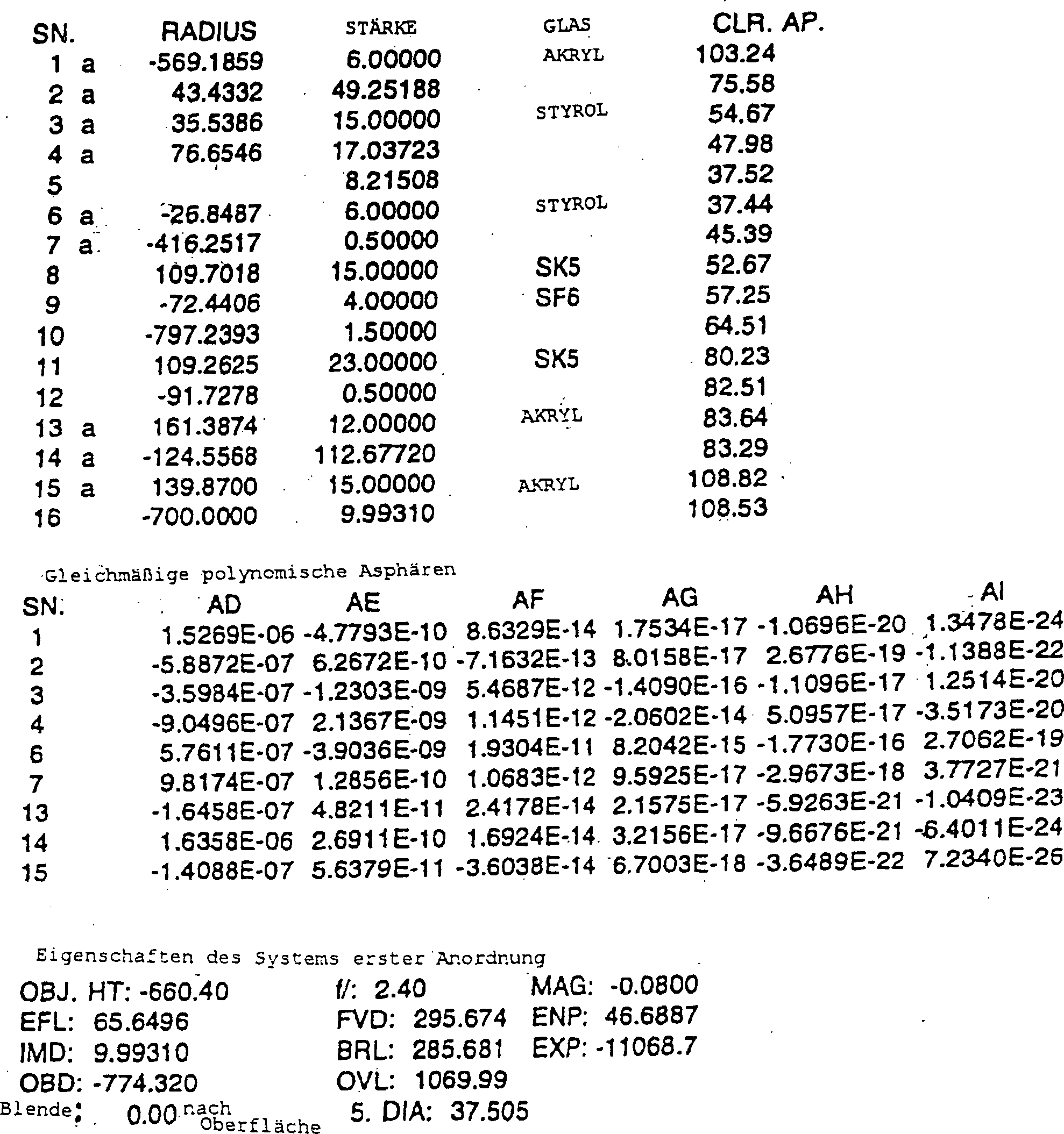
Tabelle
4 
Tabelle
5 
Tabelle
6 
Tabelle
7 
Tabelle
8 
Tabelle
9 
Tabelle
10 
Tabelle
11 
Tabelle
11 (fortgesetzt) 
Tabelle
12 
Tabelle
13 
Tabelle
14 
Tabelle
15 
Tabelle
16 
Tabelle
17 
Claims (21)
Applications Claiming Priority (3)
| Application Number | Priority Date | Filing Date | Title |
|---|---|---|---|
| US350652 | 1994-12-07 | ||
| US08/350,652 US5625495A (en) | 1994-12-07 | 1994-12-07 | Telecentric lens systems for forming an image of an object composed of pixels |
| PCT/US1995/014582 WO1996018124A1 (en) | 1994-12-07 | 1995-11-09 | Telecentric lens systems for forming an image of an object composed of pixels |
Publications (2)
| Publication Number | Publication Date |
|---|---|
| DE69530938D1 DE69530938D1 (en) | 2003-07-03 |
| DE69530938T2 true DE69530938T2 (en) | 2004-03-11 |
Family
ID=23377632
Family Applications (1)
| Application Number | Title | Priority Date | Filing Date |
|---|---|---|---|
| DE69530938T Expired - Fee Related DE69530938T2 (en) | 1994-12-07 | 1995-11-09 | TELECENTRIC LENSES FOR IMAGING AN OBJECT consisting of PIXELS |
Country Status (6)
| Country | Link |
|---|---|
| US (2) | US5625495A (en) |
| EP (1) | EP0796450B1 (en) |
| JP (1) | JPH11500834A (en) |
| KR (1) | KR100387123B1 (en) |
| DE (1) | DE69530938T2 (en) |
| WO (1) | WO1996018124A1 (en) |
Families Citing this family (133)
| Publication number | Priority date | Publication date | Assignee | Title |
|---|---|---|---|---|
| US5963375A (en) * | 1996-01-31 | 1999-10-05 | U.S. Precision Lens Inc. | Athermal LCD projection lens |
| WO1997041461A1 (en) * | 1996-04-29 | 1997-11-06 | U.S. Precision Lens Incorporated | Lcd projection lens |
| US5841587A (en) * | 1996-04-29 | 1998-11-24 | U.S. Precision Lens Inc. | LCD projection lens |
| US5870228A (en) * | 1996-05-24 | 1999-02-09 | U.S. Precision Lens Inc. | Projection lenses having larger back focal length to focal length ratios |
| US5969874A (en) * | 1996-05-30 | 1999-10-19 | U.S. Precision Lens Incorporated | Long focal length projection lenses |
| EP0825474B1 (en) * | 1996-08-16 | 2003-11-26 | 3M Innovative Properties Company | Mini-zoom projection lenses for use with pixelized panels |
| US5991089A (en) * | 1997-01-31 | 1999-11-23 | U.S. Precision Lens Inc. | Long focal length projection lenses for use with large pixelized panels |
| US5900987A (en) * | 1997-02-13 | 1999-05-04 | U.S. Precision Lens Inc | Zoom projection lenses for use with pixelized panels |
| JPH10239584A (en) * | 1997-02-25 | 1998-09-11 | Fuji Photo Optical Co Ltd | Telecentric projecting lens |
| KR100463329B1 (en) * | 1997-07-11 | 2005-05-03 | 삼성테크윈 주식회사 | Color Charge Coupled Imaging Optical System |
| US6324014B1 (en) | 1997-11-13 | 2001-11-27 | Corning Precision Lens | Wide field of view projection lenses for compact projection lens systems employing pixelized panels |
| US6198577B1 (en) | 1998-03-10 | 2001-03-06 | Glaxo Wellcome, Inc. | Doubly telecentric lens and imaging system for multiwell plates |
| US6208470B1 (en) * | 1998-06-23 | 2001-03-27 | Texas Instruments Incorporated | Telecentric projection lens |
| JP2000111793A (en) * | 1998-09-30 | 2000-04-21 | Fuji Xerox Co Ltd | Image forming optical system and image forming device |
| US6535249B1 (en) * | 1998-11-03 | 2003-03-18 | Hewlett-Packard Development Company, L.P. | Digital camera optical system with field lens |
| US6301057B1 (en) | 1999-02-02 | 2001-10-09 | Corning Precision Lens | Long focal length projection lenses |
| US6195209B1 (en) * | 1999-05-04 | 2001-02-27 | U.S. Precision Lens Incorporated | Projection lenses having reduced lateral color for use with pixelized panels |
| JP3390402B2 (en) | 1999-07-02 | 2003-03-24 | 三菱電機株式会社 | Retrofocus lens and projection display device |
| JP3402464B2 (en) | 2000-05-17 | 2003-05-06 | 三菱電機株式会社 | Retrofocus lens and projection display device |
| DE10058173A1 (en) | 2000-11-22 | 2002-05-23 | Jos Schneider Optische Werke G | Projection objective lens arrangement e.g. for movie-theater projection, has diaphragm arranged between second lens and third lens element |
| US6563650B2 (en) | 2001-01-17 | 2003-05-13 | 3M Innovative Properties Company | Compact, telecentric projection lenses for use with pixelized panels |
| JP3442744B2 (en) | 2001-02-14 | 2003-09-02 | 三菱電機株式会社 | Wide-angle projection lens and projection display device |
| US6476974B1 (en) | 2001-02-28 | 2002-11-05 | Corning Precision Lens Incorporated | Projection lenses for use with reflective pixelized panels |
| US6731434B1 (en) | 2001-05-23 | 2004-05-04 | University Of Central Florida | Compact lens assembly for the teleportal augmented reality system |
| KR100750929B1 (en) * | 2001-07-10 | 2007-08-22 | 삼성전자주식회사 | Liquid crystal display with a function of color correction, and apparatus and method for driving thereof |
| US6515801B1 (en) | 2001-12-21 | 2003-02-04 | Koninklijke Philips Electronics N.V. | Lateral color compensation for projection displays |
| JP4157305B2 (en) * | 2002-02-13 | 2008-10-01 | 株式会社ミツトヨ | Telecentric lens system and image measuring device |
| BR0316337A (en) * | 2002-12-04 | 2005-09-27 | Thomson Licensing Sa | Lens system for relaying an image maker to image maker |
| US6853493B2 (en) | 2003-01-07 | 2005-02-08 | 3M Innovative Properties Company | Folded, telecentric projection lenses for use with pixelized panels |
| JP4366086B2 (en) * | 2003-01-30 | 2009-11-18 | 日東光学株式会社 | Projection lens system and projector apparatus |
| US7119965B1 (en) | 2003-02-24 | 2006-10-10 | University Of Central Florida Research Foundation, Inc. | Head mounted projection display with a wide field of view |
| US6765731B1 (en) * | 2003-03-28 | 2004-07-20 | 3M Innovative Properties Company | Low element count projection lenses for use with pixelized panels |
| US7271964B2 (en) * | 2003-12-05 | 2007-09-18 | 3M Innovative Properties Company | Projection display device for multimedia and wall display systems |
| TW200528757A (en) * | 2003-12-05 | 2005-09-01 | 3M Innovative Properties Co | Wide-angle projection lens and optical engine for a projection display device |
| US7123426B2 (en) * | 2003-12-05 | 2006-10-17 | 3M Innovative Properties Company | Projection lens and display device |
| US7126767B2 (en) * | 2003-12-05 | 2006-10-24 | 3M Innovative Properties Company | Wide-angle projection lens for front projection display systems |
| WO2005096056A1 (en) * | 2004-03-19 | 2005-10-13 | Thomson Licensing S. A. | Anti-aliasing projection lens |
| US7009777B2 (en) * | 2004-06-02 | 2006-03-07 | 3M Innovative Properties Company | Compact projection lenses for use with large format pixelized panels |
| US7259801B2 (en) * | 2004-06-02 | 2007-08-21 | 3M Innovative Properties Company | Large-panel table-top rear projection television |
| US7002753B2 (en) * | 2004-06-02 | 2006-02-21 | 3M Innovative Properties Company | Color-corrected projection lenses for use with pixelized panels |
| US7145729B2 (en) | 2004-08-04 | 2006-12-05 | 3M Innovative Properties Company | Foldable projection lenses |
| US7230770B2 (en) * | 2004-08-04 | 2007-06-12 | 3M Innovative Properties Company | Projection lenses having color-correcting rear lens units |
| US20060028741A1 (en) * | 2004-08-04 | 2006-02-09 | 3M Innovative Properties Company | Projection lenses having color-correcting rear lens units |
| US20060060653A1 (en) * | 2004-09-23 | 2006-03-23 | Carl Wittenberg | Scanner system and method for simultaneously acquiring data images from multiple object planes |
| KR100677134B1 (en) * | 2004-09-24 | 2007-02-02 | 삼성전자주식회사 | Slim projection optical system and image display device |
| US20060285090A1 (en) * | 2004-12-03 | 2006-12-21 | 3M Innovative Properties Company | Projection lens and portable display device for gaming and other applications |
| US7342723B2 (en) * | 2004-12-03 | 2008-03-11 | 3M Innovative Properties Company | Projection lens and portable display device for gaming and other applications |
| US7173777B1 (en) | 2006-02-14 | 2007-02-06 | 3M Innovative Properties Company | Projection lens and display device for multimedia and other systems |
| WO2006076542A2 (en) * | 2005-01-12 | 2006-07-20 | Colorlink, Inc. | Illumination attenuation system |
| US7499090B2 (en) | 2005-01-27 | 2009-03-03 | Datalogic Scanning, Inc. | Rolling-reset imager with optical filter |
| US7215493B2 (en) | 2005-01-27 | 2007-05-08 | Psc Scanning, Inc. | Imaging system with a lens having increased light collection efficiency and a deblurring equalizer |
| US7224540B2 (en) * | 2005-01-31 | 2007-05-29 | Datalogic Scanning, Inc. | Extended depth of field imaging system using chromatic aberration |
| ATE403922T1 (en) * | 2005-06-02 | 2008-08-15 | Bosch Gmbh Robert | DOME WITH OPTICAL CORRECTION |
| GB0522968D0 (en) | 2005-11-11 | 2005-12-21 | Popovich Milan M | Holographic illumination device |
| JP4667269B2 (en) * | 2006-02-24 | 2011-04-06 | Hoya株式会社 | Wide-angle lens system |
| GB0718706D0 (en) | 2007-09-25 | 2007-11-07 | Creative Physics Ltd | Method and apparatus for reducing laser speckle |
| JP2009533710A (en) * | 2006-04-10 | 2009-09-17 | ニング,アレックス | Super wide-angle objective lens |
| JP3926380B1 (en) * | 2006-12-07 | 2007-06-06 | マイルストーン株式会社 | Imaging lens |
| US7857463B2 (en) * | 2007-03-29 | 2010-12-28 | Texas Instruments Incorporated | Optical system for a thin, low-chin, projection television |
| US7967448B2 (en) * | 2007-07-02 | 2011-06-28 | Texas Instruments Incorporated | Optical system for a thin, low-chin, projection television |
| US7808724B2 (en) * | 2007-12-27 | 2010-10-05 | Seward George H | Spectroscopy lens for telecentric sensor |
| WO2009094399A1 (en) | 2008-01-22 | 2009-07-30 | The Arizona Board Of Regents On Behalf Of The University Of Arizona | Head-mounted projection display using reflective microdisplays |
| JP5418745B2 (en) * | 2008-03-04 | 2014-02-19 | 株式会社ニコン | Photographic lens and optical apparatus provided with the photographic lens |
| US7988306B2 (en) * | 2008-10-02 | 2011-08-02 | Eastman Kodak Company | Afocal attachment for projection lens |
| US20120081800A1 (en) | 2009-04-20 | 2012-04-05 | Dewen Cheng | Optical see-through free-form head-mounted display |
| US11726332B2 (en) | 2009-04-27 | 2023-08-15 | Digilens Inc. | Diffractive projection apparatus |
| US9335604B2 (en) | 2013-12-11 | 2016-05-10 | Milan Momcilo Popovich | Holographic waveguide display |
| US20110075257A1 (en) | 2009-09-14 | 2011-03-31 | The Arizona Board Of Regents On Behalf Of The University Of Arizona | 3-Dimensional electro-optical see-through displays |
| US9341846B2 (en) | 2012-04-25 | 2016-05-17 | Rockwell Collins Inc. | Holographic wide angle display |
| US11204540B2 (en) | 2009-10-09 | 2021-12-21 | Digilens Inc. | Diffractive waveguide providing a retinal image |
| EP2564259B1 (en) | 2010-04-30 | 2015-01-21 | Beijing Institute Of Technology | Wide angle and high resolution tiled head-mounted display device |
| US8649094B2 (en) * | 2010-05-21 | 2014-02-11 | Eastman Kodak Company | Low thermal stress birefringence imaging lens |
| CN103080808B (en) | 2010-08-27 | 2015-07-01 | 3M创新有限公司 | Wide-angle projection lens for projection display systems |
| WO2012027096A2 (en) | 2010-08-27 | 2012-03-01 | 3M Innovative Properties Company | Projection lens for projection display systems |
| TW201209471A (en) * | 2010-08-30 | 2012-03-01 | Young Optics Inc | Lens module |
| WO2012105181A1 (en) * | 2011-01-31 | 2012-08-09 | 富士フイルム株式会社 | Projection lens and projection-type display device |
| WO2012136970A1 (en) | 2011-04-07 | 2012-10-11 | Milan Momcilo Popovich | Laser despeckler based on angular diversity |
| US8867140B2 (en) * | 2011-08-22 | 2014-10-21 | Bae Systems Information And Electronic Systems Integration Inc. | Low distortion athermalized imaging lens |
| WO2016020630A2 (en) | 2014-08-08 | 2016-02-11 | Milan Momcilo Popovich | Waveguide laser illuminator incorporating a despeckler |
| US20140204455A1 (en) | 2011-08-24 | 2014-07-24 | Milan Momcilo Popovich | Wearable data display |
| US10670876B2 (en) | 2011-08-24 | 2020-06-02 | Digilens Inc. | Waveguide laser illuminator incorporating a despeckler |
| WO2013102759A2 (en) | 2012-01-06 | 2013-07-11 | Milan Momcilo Popovich | Contact image sensor using switchable bragg gratings |
| KR102264765B1 (en) | 2012-01-24 | 2021-06-11 | 더 아리조나 보드 오브 리전츠 온 비핼프 오브 더 유니버시티 오브 아리조나 | Compact eye-tracked head-mounted display |
| WO2013167864A1 (en) | 2012-05-11 | 2013-11-14 | Milan Momcilo Popovich | Apparatus for eye tracking |
| CN110022472B (en) | 2012-10-18 | 2022-07-26 | 亚利桑那大学评议会 | Stereoscopic display with addressable focus cues |
| US9933684B2 (en) * | 2012-11-16 | 2018-04-03 | Rockwell Collins, Inc. | Transparent waveguide display providing upper and lower fields of view having a specific light output aperture configuration |
| US11885738B1 (en) | 2013-01-22 | 2024-01-30 | J.A. Woollam Co., Inc. | Reflectometer, spectrophotometer, ellipsometer or polarimeter system including sample imaging system that simultaneously meet the scheimpflug condition and overcomes keystone error |
| WO2014188149A1 (en) | 2013-05-20 | 2014-11-27 | Milan Momcilo Popovich | Holographic waveguide eye tracker |
| US9727772B2 (en) | 2013-07-31 | 2017-08-08 | Digilens, Inc. | Method and apparatus for contact image sensing |
| EP3114526B1 (en) | 2014-03-05 | 2021-10-20 | Arizona Board of Regents on Behalf of the University of Arizona | Wearable 3d augmented reality display |
| JP6440375B2 (en) * | 2014-04-10 | 2018-12-19 | キヤノン株式会社 | Optical system and imaging apparatus having the same |
| US10359736B2 (en) | 2014-08-08 | 2019-07-23 | Digilens Inc. | Method for holographic mastering and replication |
| US10241330B2 (en) | 2014-09-19 | 2019-03-26 | Digilens, Inc. | Method and apparatus for generating input images for holographic waveguide displays |
| WO2016046514A1 (en) | 2014-09-26 | 2016-03-31 | LOKOVIC, Kimberly, Sun | Holographic waveguide opticaltracker |
| CN107873086B (en) | 2015-01-12 | 2020-03-20 | 迪吉伦斯公司 | Environmentally isolated waveguide display |
| WO2016113533A2 (en) | 2015-01-12 | 2016-07-21 | Milan Momcilo Popovich | Holographic waveguide light field displays |
| US10330777B2 (en) | 2015-01-20 | 2019-06-25 | Digilens Inc. | Holographic waveguide lidar |
| US10176961B2 (en) | 2015-02-09 | 2019-01-08 | The Arizona Board Of Regents On Behalf Of The University Of Arizona | Small portable night vision system |
| US9632226B2 (en) | 2015-02-12 | 2017-04-25 | Digilens Inc. | Waveguide grating device |
| US10459145B2 (en) | 2015-03-16 | 2019-10-29 | Digilens Inc. | Waveguide device incorporating a light pipe |
| US10591756B2 (en) | 2015-03-31 | 2020-03-17 | Digilens Inc. | Method and apparatus for contact image sensing |
| TWI586998B (en) | 2015-08-11 | 2017-06-11 | 大立光電股份有限公司 | Photographing optical lens system, image capturing unit and electronic device |
| WO2017060665A1 (en) | 2015-10-05 | 2017-04-13 | Milan Momcilo Popovich | Waveguide display |
| JP6246433B2 (en) * | 2015-10-16 | 2017-12-13 | オリンパス株式会社 | Endoscope objective optical system |
| CN109073889B (en) | 2016-02-04 | 2021-04-27 | 迪吉伦斯公司 | Holographic waveguide optical tracker |
| WO2017162999A1 (en) | 2016-03-24 | 2017-09-28 | Popovich Milan Momcilo | Method and apparatus for providing a polarization selective holographic waveguide device |
| JP6734933B2 (en) | 2016-04-11 | 2020-08-05 | ディジレンズ インコーポレイテッド | Holographic Waveguide Device for Structured Light Projection |
| US10739578B2 (en) | 2016-08-12 | 2020-08-11 | The Arizona Board Of Regents On Behalf Of The University Of Arizona | High-resolution freeform eyepiece design with a large exit pupil |
| WO2018102834A2 (en) | 2016-12-02 | 2018-06-07 | Digilens, Inc. | Waveguide device with uniform output illumination |
| WO2018129398A1 (en) | 2017-01-05 | 2018-07-12 | Digilens, Inc. | Wearable heads up displays |
| EP3593195B1 (en) | 2017-03-09 | 2023-12-06 | ARIZONA BOARD OF REGENTS on behalf of THE UNIVERSITY OF ARIZONA | Head-mounted light field display with integral imaging and relay optics |
| AU2018231083B2 (en) | 2017-03-09 | 2023-03-09 | Arizona Board Of Regents On Behalf Of The University Of Arizona | Head-mounted light field display with integral imaging and waveguide prism |
| JP7399084B2 (en) | 2017-10-16 | 2023-12-15 | ディジレンズ インコーポレイテッド | System and method for doubling the image resolution of pixelated displays |
| JP7135298B2 (en) * | 2017-10-27 | 2022-09-13 | 株式会社リコー | Projection optical system, image projection device |
| WO2019136476A1 (en) | 2018-01-08 | 2019-07-11 | Digilens, Inc. | Waveguide architectures and related methods of manufacturing |
| US20190212588A1 (en) | 2018-01-08 | 2019-07-11 | Digilens, Inc. | Systems and Methods for Manufacturing Waveguide Cells |
| JP7404243B2 (en) | 2018-01-08 | 2023-12-25 | ディジレンズ インコーポレイテッド | Systems and methods for high-throughput recording of holographic gratings in waveguide cells |
| EP4372451A3 (en) | 2018-03-16 | 2024-08-14 | Digilens Inc. | Holographic waveguides incorporating birefringence control and methods for their fabrication |
| EP3769512A4 (en) | 2018-03-22 | 2021-03-24 | Arizona Board of Regents on Behalf of the University of Arizona | Methods of rendering light field images for integral-imaging-based light field display |
| US11402801B2 (en) | 2018-07-25 | 2022-08-02 | Digilens Inc. | Systems and methods for fabricating a multilayer optical structure |
| US11203156B2 (en) | 2018-08-20 | 2021-12-21 | NEXA3D Inc. | Methods and systems for photo-curing photo-sensitive material for printing and other applications |
| IL282910B2 (en) | 2018-11-09 | 2024-08-01 | Nexa3D Inc | Three-dimensional printing system |
| EP3924759A4 (en) | 2019-02-15 | 2022-12-28 | Digilens Inc. | Methods and apparatuses for providing a holographic waveguide display using integrated gratings |
| JP2022525165A (en) | 2019-03-12 | 2022-05-11 | ディジレンズ インコーポレイテッド | Holographic Waveguide Backlights and Related Manufacturing Methods |
| WO2020190360A1 (en) | 2019-03-18 | 2020-09-24 | NEXA3D Inc. | Method and system for additive manufacture |
| US10967573B2 (en) | 2019-04-02 | 2021-04-06 | NEXA3D Inc. | Tank assembly and components thereof for a 3D printing system |
| US20200386947A1 (en) | 2019-06-07 | 2020-12-10 | Digilens Inc. | Waveguides Incorporating Transmissive and Reflective Gratings and Related Methods of Manufacturing |
| TWI691751B (en) | 2019-06-14 | 2020-04-21 | 大立光電股份有限公司 | Optical photographing lens assembly, image capturing unit and electronic device |
| US10656368B1 (en) | 2019-07-24 | 2020-05-19 | Omniome, Inc. | Method and system for biological imaging using a wide field objective lens |
| EP4004646A4 (en) | 2019-07-29 | 2023-09-06 | Digilens Inc. | Methods and apparatus for multiplying the image resolution and field-of-view of a pixelated display |
| KR20220054386A (en) | 2019-08-29 | 2022-05-02 | 디지렌즈 인코포레이티드. | Vacuum Bragg grating and manufacturing method thereof |
| CN111897107B (en) * | 2020-07-28 | 2021-07-27 | 中国科学院西安光学精密机械研究所 | Medium wave infrared athermalization lens |
| CN114089513B (en) * | 2021-10-22 | 2023-12-12 | 浙江大立科技股份有限公司 | Infrared ultra-wide temperature athermal optical system at-70 ℃ to +100 DEG C |
Family Cites Families (36)
| Publication number | Priority date | Publication date | Assignee | Title |
|---|---|---|---|---|
| US706650A (en) * | 1900-11-05 | 1902-08-12 | Carl Paul Goerz | Astigmatically-corrected wide-angle objective. |
| US2031792A (en) * | 1933-07-26 | 1936-02-25 | Zeiss Carl Fa | Anastigmatic objective for photography and projection |
| JPS5840166B2 (en) * | 1973-03-15 | 1983-09-03 | キヤノン株式会社 | Retro Telecentric Cleanse Kay |
| JPS5829487B2 (en) * | 1974-09-04 | 1983-06-23 | キヤノン株式会社 | Retro Focus Lens |
| DE2514081C2 (en) * | 1975-03-29 | 1982-09-09 | Fa. Carl Zeiss, 7920 Heidenheim | Very bright wide-angle lens with a long focal length on the image side |
| SU603938A1 (en) * | 1976-12-22 | 1978-04-25 | Предприятие П/Я Р-6681 | Telecentric objective lens |
| US4189211A (en) * | 1978-01-03 | 1980-02-19 | Kollmorgen Corporation | Wide angle telecentric projection lens assembly |
| US4441792A (en) * | 1980-03-04 | 1984-04-10 | Canon Kabushiki Kaisha | Telecentric projection lenses |
| US4637690A (en) * | 1981-04-06 | 1987-01-20 | Konishiroku Photo Industry Co., Ltd. | Telecentric zoom lens system |
| JPS57208523A (en) * | 1981-06-19 | 1982-12-21 | Nippon Kogaku Kk <Nikon> | Telecentric variable magnification lighting system |
| SU1007068A1 (en) * | 1981-07-14 | 1983-03-23 | Предприятие П/Я Р-6681 | Objective |
| US4425028A (en) * | 1981-12-28 | 1984-01-10 | Hughes Aircraft Company | High efficiency optical tank for three color liquid crystal light valve image projection with color selective prepolarization and single projection lens |
| US4461542A (en) * | 1981-12-28 | 1984-07-24 | Hughes Aircraft Company | High efficiency optical tank for three color liquid crystal light valve image projection with color selective prepolarization |
| SU1048444A1 (en) * | 1982-05-21 | 1983-10-15 | Ленинградский Ордена Трудового Красного Знамени Институт Точной Механики И Оптики | Wide-angled telecentrical lens |
| US5210646A (en) | 1982-09-20 | 1993-05-11 | Lockheed Missiles & Space Company, Inc. | Color-corrected optical systems and method of selecting optical materials therefor |
| SU1089535A1 (en) * | 1983-01-25 | 1984-04-30 | Предприятие П/Я Р-6681 | Zoom lens |
| JPS62266512A (en) * | 1986-05-14 | 1987-11-19 | Canon Inc | Telecentric zoom lens |
| US4826311A (en) * | 1987-07-24 | 1989-05-02 | Hughes Aircraft Company | Prism assembly with three periscopes and projection lenses for a single light valve full-color projector |
| US4989954A (en) * | 1987-10-09 | 1991-02-05 | Matsushita Electric Industrial Co., Ltd. | Projection type liquid cyrstal display device |
| JP2717552B2 (en) * | 1988-07-30 | 1998-02-18 | 旭光学工業株式会社 | Telecentric projection lens |
| JPH0679103B2 (en) * | 1988-09-20 | 1994-10-05 | 大日本スクリーン製造株式会社 | Telecentric fθ lens |
| JPH0296709A (en) * | 1988-10-04 | 1990-04-09 | Canon Inc | Telecentric optical system |
| JPH07113706B2 (en) * | 1988-12-16 | 1995-12-06 | 大日本スクリーン製造株式会社 | Optical beam scanning lens |
| JPH03288112A (en) | 1990-04-04 | 1991-12-18 | Dainippon Screen Mfg Co Ltd | Achromatic lens system |
| JPH0413108A (en) * | 1990-05-02 | 1992-01-17 | Matsushita Electric Ind Co Ltd | Projection lens and projection television using the same lens |
| US5172275A (en) | 1990-12-14 | 1992-12-15 | Eastman Kodak Company | Apochromatic relay lens systems suitable for use in a high definition telecine apparatus |
| JPH04335610A (en) | 1991-05-13 | 1992-11-24 | Nikon Corp | Projection lens |
| US5200861A (en) * | 1991-09-27 | 1993-04-06 | U.S. Precision Lens Incorporated | Lens systems |
| US5390048A (en) | 1991-12-02 | 1995-02-14 | Matsushita Electric Industrial Co., Ltd. | Projection lens assembly and projection display apparatus |
| JP2924377B2 (en) | 1991-12-02 | 1999-07-26 | 松下電器産業株式会社 | Projection lens and projection display device |
| JPH05150158A (en) | 1991-12-02 | 1993-06-18 | Matsushita Electric Ind Co Ltd | Projection lens and projection type display device |
| US5218480A (en) * | 1991-12-03 | 1993-06-08 | U.S. Precision Lens Incorporated | Retrofocus wide angle lens |
| DE4208635C1 (en) * | 1992-03-18 | 1993-07-22 | Jenoptik Gmbh, O-6900 Jena, De | Telecentric objective lens with double Gaussian objective - couples lens contents into image conducting fibres with higher illuminating strength at picture edges |
| US5313330A (en) * | 1992-08-31 | 1994-05-17 | U.S. Precision Lens Incorporated | Zoom projection lens systems |
| JPH06317742A (en) * | 1993-05-10 | 1994-11-15 | Casio Comput Co Ltd | Projection lens |
| JPH0777652A (en) | 1993-09-08 | 1995-03-20 | Matsushita Electric Ind Co Ltd | Projection lens and projection type display device |
-
1994
- 1994-12-07 US US08/350,652 patent/US5625495A/en not_active Ceased
-
1995
- 1995-11-09 DE DE69530938T patent/DE69530938T2/en not_active Expired - Fee Related
- 1995-11-09 EP EP95940662A patent/EP0796450B1/en not_active Expired - Lifetime
- 1995-11-09 WO PCT/US1995/014582 patent/WO1996018124A1/en active IP Right Grant
- 1995-11-09 KR KR1019970703782A patent/KR100387123B1/en not_active IP Right Cessation
- 1995-11-09 JP JP8517591A patent/JPH11500834A/en active Pending
-
1999
- 1999-04-28 US US09/305,780 patent/USRE39424E1/en not_active Expired - Lifetime
Also Published As
| Publication number | Publication date |
|---|---|
| EP0796450A1 (en) | 1997-09-24 |
| KR100387123B1 (en) | 2003-10-10 |
| EP0796450B1 (en) | 2003-05-28 |
| US5625495A (en) | 1997-04-29 |
| WO1996018124A1 (en) | 1996-06-13 |
| KR987000587A (en) | 1998-03-30 |
| DE69530938D1 (en) | 2003-07-03 |
| USRE39424E1 (en) | 2006-12-12 |
| JPH11500834A (en) | 1999-01-19 |
Similar Documents
| Publication | Publication Date | Title |
|---|---|---|
| DE69530938T2 (en) | TELECENTRIC LENSES FOR IMAGING AN OBJECT consisting of PIXELS | |
| DE69724115T2 (en) | PROJECTION LENS FOR LIQUID CRYSTAL DISPLAY | |
| DE69929824T2 (en) | COLOR-CORRUPTED PROJECTION LINES USING DIFFERENT OPTICAL SURFACES | |
| DE69723772T2 (en) | Projection lenses with a large ratio between the focal distance from the back of the lens to the focal length | |
| DE69629257T2 (en) | Lens system for television projection device | |
| DE19618783C2 (en) | Wide-angle lens | |
| DE69724602T2 (en) | LENS SYSTEM FOR PROJECTION TELEVISION | |
| EP0662274B1 (en) | Colour video image projection system and associated transformation optics | |
| DE102013003551B4 (en) | PROJECTION LENS AND PROJECTION DEVICE | |
| DE69328891T2 (en) | Systems for projection zoom lenses | |
| EP2294483B1 (en) | Projection system | |
| EP2083302A2 (en) | Optical system for digital cinema projection | |
| DE102021133603A1 (en) | Four piece large aperture optical objective | |
| DE2739488B2 (en) | Wide angle photographic lens | |
| DE3108018C2 (en) | ||
| DE69530162T2 (en) | projection lens | |
| EP1489451B1 (en) | Projection lens with high aperture ratio | |
| DE2035424A1 (en) | Afocal enlarging lens | |
| DE69023523T2 (en) | Projection lens and television projection system with such a lens. | |
| WO2004039084A1 (en) | Arrangement for projecting an image onto a projection surface and associated transformation lens system | |
| DE19614379A1 (en) | Projector with removable LCD surface | |
| DE4443936A1 (en) | Optical projection device for a liquid crystal projector | |
| DE69118776T2 (en) | Large display device | |
| DE2432589A1 (en) | PHOTO LENS | |
| DE602004001027T2 (en) | Photo lens |
Legal Events
| Date | Code | Title | Description |
|---|---|---|---|
| 8327 | Change in the person/name/address of the patent owner |
Owner name: 3M INNOVATIVE PROPERTIES CO., ST. PAUL, MINN., US |
|
| 8364 | No opposition during term of opposition | ||
| 8339 | Ceased/non-payment of the annual fee |