Die vorliegende Erfindung bezieht sich auf eine Oszillationsvorrichtung zum Einstellen des Oszillationszustands einer oszillierenden bzw. sich hin- und herbewegenden Walze eines Farbwerks einer Druckmaschine.The present invention relates to an oscillation apparatus for adjusting the state of oscillation of an oscillating or reciprocating roller of an inking unit of a printing machine.
Wenn Wertpapiere oder dergleichen gedruckt werden, wird zur Verhinderung von Fälschungen Regenbogendruck durchgeführt. Wenn ein solcher Regenbogendruck durchgeführt wird, spielt eine Oszillationsvorrichtung zum Einstellen des Oszillationszustands einer oszillierenden bzw. sich hin- und herbewegenden Walze eines Farbwerks eine sehr wichtige Rolle. Eine solche herkömmliche Oszillationsvorrichtung wird unter Bezugnahme auf 12 beschrieben.When printing securities or the like, rainbow printing is performed to prevent counterfeiting. When such a rainbow pressure is applied, an oscillating device for adjusting the state of oscillation of an oscillating or reciprocating roller of an inking unit plays a very important role. Such a conventional oscillation apparatus will be described with reference to FIG 12 described.
In einer Farbquelle eines Farbwerks gespeicherte Farbe wird oszillierenden Walzen 101 und 102 einer Druckmaschine zugeführt, und eine Hydraulikpumpe 112 wird betrieben, um einem Hydraulikzylinder 115 ein Arbeitsfluid aus einem Hydrauliktank 111 zuzuführen. Als ein Ergebnis wird die oszillierende Walze 101 entlang ihrer axialen Richtung hin- und herbewegt, und die oszillierende Walze 102 wird über einen Oszillationshebel 103 ebenfalls entlang ihrer axialen Richtung hin- und herbewegt, so dass Farbe einem Plattenzylinder zugeführt wird, während sie in der axialen Richtung der oszillierenden Walzen 101 und 102 verteilt wird.Color stored in a color source of an inking unit becomes oscillating rollers 101 and 102 fed to a printing press, and a hydraulic pump 112 is operated to a hydraulic cylinder 115 a working fluid from a hydraulic tank 111 supply. As a result, the oscillating roll becomes 101 along its axial direction reciprocated, and the oscillating roller 102 is via an oscillation lever 103 is also reciprocated along its axial direction so that ink is supplied to a plate cylinder while in the axial direction of the oscillating rollers 101 and 102 is distributed.
Die Oszillationszahl der oszillierenden Walze 102 wird mittels eines Differentialtransformators 118 in ein elektrisches Signal umgewandelt, und das elektrische Signal wird einem Verstärker 116 zugeführt. Die Drehzahl eines Gegendruckzylinders 100 wird mittels eines Drehgebers 117 in ein Impulssignal umgewandelt, und das Impulssignal wird dem Verstärker 116 zugeführt. Wenn die Oszillationsweite (oscillation width) der oszillierenden Walzen 101 und 102 durch den Betrieb eines Reglers 119 eingestellt wird, werden die dem Verstärker 116 zugeführten Signale und die eingestellte Oszillationsweite berechnet, um ein Signal zu erhalten, das einen Sollwert angibt und an ein Durchflussregelventil 113 ausgegeben wird. Ferner werden während der durch Verwendung des Reglers 119 eingestellte Wert und das Signal von dem Differentialtransformator 118 miteinander verglichen werden, Impulse von dem Drehgeber 117 berechnet, um ein Signal mit einer vorbestimmten zeitlichen Steuerung an ein Richtungssteuerungsventil 114 auszugeben, die zu dem Betrieb der Druckmaschine passt. Durch die oben beschriebene Arbeitsweise, die kontinuierlich in dem Verstärker 116 durchgeführt wird, kann der Oszillationszustand (Oszillationsweite und Oszillationszahl) der oszillierenden Walzen 101 und 102 eingestellt werden (siehe die japanische Patentanmeldung mit der Offenlegungsnummer (kokai) 63-264352 und die japanische Gebrauchsmusteranmeldung mit der Offenlegungsnummer (kokai) 63-170138 ).The oscillation number of the oscillating roller 102 is by means of a differential transformer 118 converted into an electrical signal, and the electrical signal becomes an amplifier 116 fed. The speed of a counter-pressure cylinder 100 is by means of a rotary encoder 117 converted into a pulse signal, and the pulse signal becomes the amplifier 116 fed. When the oscillation width of the oscillating rollers 101 and 102 through the operation of a regulator 119 is adjusted, which are the amplifier 116 supplied signals and the set oscillation range calculated to obtain a signal indicative of a setpoint and to a flow control valve 113 is issued. Further, while using the regulator 119 set value and the signal from the differential transformer 118 be compared with each other, pulses from the encoder 117 calculated to a signal with a predetermined timing to a directional control valve 114 output, which fits the operation of the printing press. Through the above-described operation, which is continuous in the amplifier 116 is performed, the oscillation state (oscillation width and oscillation number) of the oscillating rollers 101 and 102 be set (see the Japanese Patent Application Laid-Open (kokai) No. 63-264352 and the Japanese Utility Model Application Laid-Open (kokai) No. 63-170138 ).
Die herkömmlichen Oszillationsvorrichtungen, wie sie oben beschrieben wurden, haben die folgenden Probleme.
- (1) Da die Menge und die Richtung des dem Hydraulikzylinder 115 zugeführten Fluids durch das Durchflussregelventil 113 und das Richtungssteuerungsventil 114 gesteuert werden, um dadurch die Oszillationsweite und die Oszillationszahl der oszillierenden Walzen 101 und 102 einzustellen, ist der Mechanismus zum Steuern des Hydraulikzylinders 115 kompliziert.
- (2) Eine unzureichende Ansprechempfindlichkeit des Hydraulikzylinders 115 macht es schwer, die Oszillationsweite und die Oszillationszahl der oszillierenden Walzen 101 und 102 fein einzustellen.
The conventional oscillation devices as described above have the following problems. - (1) Because the amount and direction of the hydraulic cylinder 115 supplied fluid through the flow control valve 113 and the directional control valve 114 thereby controlling the oscillation width and the oscillation number of the oscillating rollers 101 and 102 adjust is the mechanism for controlling the hydraulic cylinder 115 complicated.
- (2) Insufficient responsiveness of the hydraulic cylinder 115 makes it hard, the oscillation and the oscillation number of the oscillating rollers 101 and 102 fine tune.
Angesichts des Vorhergehenden besteht eine Aufgabe der vorliegenden Erfindung darin, eine Oszillationsvorrichtung für eine oszillierende Walze bereitzustellen, die den Oszillationszustand der oszillierenden Walze mit hoher Ansprechempfindlichkeit durch Verwendung eines einfachen Mechanismus einstellen kann.In view of the foregoing, it is an object of the present invention to provide an oscillating roller oscillating apparatus which can adjust the oscillation state of the high-sensitivity oscillating roller by using a simple mechanism.
Um die obige Aufgabe zu lösen, wird eine Oszillationsvorrichtung mit den Merkmalen von Anspruch 1 zur Verfügung gestellt.In order to achieve the above object, an oscillation apparatus having the features of claim 1 is provided.
In der erfindungsgemäßen Oszillationsvorrichtung für eine oszillierende Walze steuert das Oszillationsweiten-Steuermittel den Betrieb des Oszillationsweiten-Einstellmotors in der Weise, dass die Oszillationsweite der oszillierenden Walze einen vorgegebenen Wert annimmt, und das Oszillationszahl-Steuermittel steuert den Betrieb des Oszillationsmechanismus-Antriebsmotors auf der Basis der Drehzahl des Plattenzylinders in der Weise, dass die Anzahl von Oszillationen der oszillierenden Walze je Umdrehungseinheitszahl des Plattenzylinders einen vorgegebenen Wert annimmt. Daher kann der Steuermechanismus für die oszillierende Walze vereinfacht werden. Da die oszillierende Walze durch die oben beschriebenen Motoren betrieben wird, kann die oszillierende Walze darüber hinaus mit einer hohen Ansprechempfindlichkeit betrieben werden, und die Oszillation der oszillierenden Walze kann fein und leicht eingestellt werden. Dementsprechend kann der Oszillationszustand der oszillierenden Walze mit hoher Ansprechempfindlichkeit durch Verwendung eines einfachen Mechanismus eingestellt werden.In the oscillating roller oscillating apparatus according to the present invention, the oscillation width control means controls the operation of the oscillation width adjusting motor such that the oscillation width of the oscillating roller assumes a predetermined value, and the oscillation number controlling means controls the operation of the oscillation mechanism driving motor on the basis of Speed of the plate cylinder in such a way that the number of oscillations of the oscillating roller per revolution unit number of the plate cylinder assumes a predetermined value. Therefore, the control mechanism for the oscillating roller can be simplified. Moreover, since the oscillating roller is operated by the above-described motors, the oscillating roller can be operated with a high responsiveness, and the oscillation of the oscillating roller can be finely and easily adjusted. Accordingly, the oscillation state of the high-sensitivity oscillating roller can be adjusted by using a simple mechanism.
1 ist eine Ansicht, die schematisch die Gesamtkonstruktion einer Ausführungsform zeigt, in der eine Oszillationsvorrichtung für eine oszillierende Walze gemäß der vorliegenden Erfindung auf eine oszillierende Walze eines Farbwerks einer doppelseitigen Mehrfarben-Offsetdruckmaschine angewendet wird, 1 FIG. 14 is a view schematically showing the overall construction of an embodiment in which an oscillating roller oscillating apparatus according to the present invention is applied to an oscillating roller of an inking unit of FIG double-sided multicolor offset printing machine is used,
2 ist eine vergrößerte Ansicht eines Farbwerkteils, 2 is an enlarged view of an inking unit part,
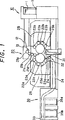
3 ist eine seitliche Schnittansicht, die schematisch die Konstruktion eines Hauptteils der Oszillationsvorrichtung für eine oszillierende Walze zeigt, 3 Fig. 15 is a sectional side view schematically showing the construction of a main part of the oscillating roller oscillating apparatus;
4 ist eine Draufsicht, wie sie aus der Richtung des Pfeils IV in 3 zu sehen ist, 4 is a top view as seen from the direction of the arrow IV in FIG 3 you can see,
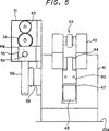
5 ist eine Vorderansicht, wie sie aus der Richtung des Pfeils V in 4 zu sehen ist, 5 is a front view as seen from the direction of the arrow V in 4 you can see,
6 ist eine horizontal geteilte Entwicklungsansicht eines Hauptteils der 3, 6 is a horizontally shared development view of a main part of 3 .
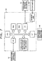
7 ist ein Blockdiagramm einer Oszillationsweiten-Steuereinrichtung, 7 FIG. 10 is a block diagram of an oscillation width control device; FIG.
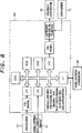
8 ist ein Blockdiagramm einer Oszillationszahl-Steuereinrichtung, 8th FIG. 12 is a block diagram of an oscillation number control device; FIG.
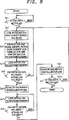
9 ist ein Flussdiagramm zur Oszillationsweitensteuerung, und 9 is a flowchart for the oscillation width control, and
10 ist ein Flussdiagramm zur Oszillationszahlsteuerung, 10 FIG. 4 is a flowchart of oscillation number control; FIG.
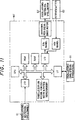
11 ist ein Blockdiagramm einer Oszillationszahl-Steuereinrichtung, und 11 FIG. 12 is a block diagram of an oscillation number controller, and FIG
12 ist eine Ansicht, die schematische die Gesamtkonstruktion einer herkömmlichen Oszillationsvorrichtung zeigt. 12 Fig. 16 is a view schematically showing the overall construction of a conventional oscillation apparatus.
Eine Ausführungsform der vorliegenden Erfindung wird unter Bezugnahme auf die 1 bis 10 beschrieben. Die Ausführungsform ist ein Farbwerk einer doppelseitigen Mehrfarben-Offsetdruckmaschine, die eine Oszillationsvorrichtung für eine oszillierende Walze gemäß der vorliegenden Erfindung einsetzt. 1 ist eine Ansicht, die schematisch die Gesamtkonstruktion einer doppelseitigen Mehrfarben-Offsetdruckmaschine zeigt, 2 ist eine vergrößerte Ansicht eines Farbwerkteils, 3 ist eine seitliche Schnittansicht, die schematisch die Konstruktion eines Hauptteils der Oszillationsvorrichtung für eine oszillierende Walze zeigt, 4 ist eine Draufsicht, wie sie aus der Richtung des Pfeils IV in 3 zu sehen ist, 5 ist eine Vorderansicht, wie sie aus der Richtung des Pfeils V in 4 zu sehen ist, 6 ist eine horizontal geteilte Entwicklungsansicht eines Hauptteils der 3, 7 ist ein Blockdiagramm einer Oszillationsweiten-Steuereinrichtung, 8 ist ein Blockdiagramm einer Oszillationszahl-Steuereinrichtung, 9 ist ein Flussdiagramm zur Oszillationsweitensteuerung, und 10 ist ein Flussdiagramm zur Oszillationszahlsteuerung.An embodiment of the present invention will be described with reference to FIGS 1 to 10 described. The embodiment is an inking unit of a double-sided multicolor offset printing machine employing an oscillating apparatus for an oscillating roller according to the present invention. 1 Fig. 12 is a view schematically showing the overall construction of a double-sided multicolor offset printing machine, 2 is an enlarged view of an inking unit part, 3 Fig. 15 is a sectional side view schematically showing the construction of a main part of the oscillating roller oscillating apparatus; 4 is a top view as seen from the direction of the arrow IV in FIG 3 you can see, 5 is a front view as seen from the direction of the arrow V in 4 you can see, 6 is a horizontally shared development view of a main part of 3 . 7 FIG. 10 is a block diagram of an oscillation width control device; FIG. 8th FIG. 12 is a block diagram of an oscillation number control device; FIG. 9 is a flowchart for the oscillation width control, and 10 is a flow chart for oscillation number control.
Wie in 1 gezeigt ist, ist ein Bogenzuführtisch 11 in einer Zuführeinheit 10 angeordnet. In der Zuführeinheit 10 ist auch eine Zuführplatte 12 vorgesehen. Die Zuführplatte 12 transportiert Papierbogen (bogenförmige Objekte) 1 von dem Bogenzuführtisch 11 zu einer Druckeinheit 20, jeweils einen Bogen zur Zeit. An dem distalen Ende der Zuführplatte 12 ist eine Schwenkvorrichtung 13 zum Transportieren der Papierbogen 1 zu einem Übertragungszylinder 21a der Druckeinheit 20 vorgesehen.As in 1 is shown is a sheet feed table 11 in a feeder unit 10 arranged. In the feeder unit 10 is also a feeder plate 12 intended. The feed plate 12 transports paper sheets (arched objects) 1 from the sheet feed table 11 to a printing unit 20 , one sheet at a time. At the distal end of the feed plate 12 is a swivel device 13 for transporting the paper sheets 1 to a transfer cylinder 21a the printing unit 20 intended.
Der Übertragungszylinder 21a befindet sich über Übertragungszylinder 21b bis 21d in Kontakt mit einem Gegendruckzylinder 22a. An der äußeren Umfangsfläche des Gegendruckzylinders 22a ist ein aus Gummi hergestelltes Tuch befestigt Ein Gummizylinder 22b berührt den Gegendruckzylinder 22a an einer in Bezug auf den Übertragungszylinder 21d nachfolgenden Stelle. Eine Vielzahl von (in der vorliegenden Ausführungsform vier) Plattenzylindern 23a befinden sich an in Bezug auf den Übertragungszylinder 21d davor liegenden Stellen in der Weise in Kontakt mit dem Gegendruckzylinder 22a, dass die Plattenzylinder 23a in vorbestimmten Abständen entlang der Umfangsrichtung angeordnet sind. Eine Vielzahl von (in der vorliegenden Ausführungsform vier) Plattenzylindern 23b befinden sich an in Bezug auf den Gegendruckzylinder 22a davor liegenden Stellen in der Weise in Kontakt mit dem Gummizylinder 22b, dass die Plattenzylinder 23b in vorbestimmten Abständen entlang der Umfangsrichtung angeordnet sind. Ein Übertragungszylinder 24 berührt den Gegendruckzylinder 22a an einer in Bezug auf den Gummizylinder 22b nachfolgenden Stelle.The transfer cylinder 21a is located above transfer cylinder 21b to 21d in contact with an impression cylinder 22a , On the outer peripheral surface of the impression cylinder 22a a cloth made of rubber is attached A rubber cylinder 22b touches the impression cylinder 22a at one with respect to the transfer cylinder 21d following place. A plurality of (four in the present embodiment) plate cylinders 23a are located in relation to the transfer cylinder 21d in front of lying in the manner in contact with the impression cylinder 22a that the plate cylinder 23a are arranged at predetermined intervals along the circumferential direction. A plurality of (four in the present embodiment) plate cylinders 23b are located in relation to the impression cylinder 22a in front of the places in contact with the blanket cylinder 22b that the plate cylinder 23b are arranged at predetermined intervals along the circumferential direction. A transfer cylinder 24 touches the impression cylinder 22a at one with respect to the blanket cylinder 22b following place.
Ein Auslegezylinder 31 einer Auslegeeinheit 30 befindet sich in Kontakt mit dem Übertragungszylinder 24. Ein Kettenrad 32 ist koaxial an dem Auslegezylinder 31 befestigt. Ferner ist ein Kettenrad 33 in der Auslegeeinheit 30 vorgesehen. Eine Auslegerkette 34 verläuft zwischen den Kettenrädern 32 und 33 und ist um diese herumgelegt. An der Auslegerkette 34 sind in vorbestimmten Abständen eine Vielzahl von Abnahmegreifern (nicht gezeigt) vorgesehen. In der Auslegeeinheit 30 sind Auslegetische 35a und 35b vorgesehen, auf denen bedruckte Papierbögen 100 angeordnet werden.An extension cylinder 31 a display unit 30 is in contact with the transfer cylinder 24 , A sprocket 32 is coaxial with the extension cylinder 31 attached. Further, a sprocket 33 in the display unit 30 intended. A boom chain 34 runs between the sprockets 32 and 33 and is wrapped around these. On the boom chain 34 At a predetermined interval, a plurality of picking grippers (not shown) are provided. In the display unit 30 are serving tables 35a and 35b provided on which printed paper sheets 100 to be ordered.
Wie in 2 gezeigt ist, ist für jeden der Plattenzylinder 23a ein Farbwerk 25 zum Zuführen von Farbe vorgesehen. Das Farbwerk 25 enthält Farbquellen 25a zum Speichern von Farbe, Farbquellenwalzen 25b zum Transportieren von Farbe aus den Farbquellen 25a, Duktorwalzen 25c zum Aufnehmen der von den Farbquellenwalzen 25b transportierten Farbe, Verteilerwalzen 25d zum Verteilen der aufgenommenen Farbe, oszillierende Walzen 25e zum Verteilen der Farbe in der axialen Richtung durch eine hin- und hergehende Bewegung entlang der axialen Richtung, Auftragswalzen 25f zum Zuführen der Farbe zu dem entsprechenden Plattenzylinder 23a und eine Antriebswalze 25g zum Drehen dieser Walzen 25b bis 25f in einer gekoppelten Weise.As in 2 is shown for each of the plate cylinder 23a an inking unit 25 intended for supplying color. The inking unit 25 contains color sources 25a for storing color, color source rollers 25b for transporting color from the color sources 25a , Ductor rollers 25c for picking up the color source rollers 25b transported paint, distributor rollers 25d for distributing the recorded color, oscillating rollers 25e to the Distributing the color in the axial direction by a reciprocating movement along the axial direction, applicator rollers 25f for supplying the ink to the corresponding plate cylinder 23a and a drive roller 25g for turning these rollers 25b to 25f in a coupled way.
Wie in den 3 bis 6 gezeigt ist, ist eine Tragbasis 41 an einem Rahmen 20a der Druckeinheit 20 befestigt, um in der Nähe einer Wellenendseite der oszillierenden Walze 25e angeordnet zu sein. An der Tragbasis 41 sind zwei L-förmige Schwenkhebel 43 vorgesehen, die als ein Schwenkelement dienen. Der gebogene Mittelabschnitt jedes Schwenkhebels 43, der sich zwischen seinem distalen Ende und seinem Basisende befindet, ist durch einen Tragstift 42 so gelagert, dass der Schwenkhebel 43 in eine Richtung hin zu der oszillierenden Walze 25e und von dieser weg schwenken kann. Die zwei Schwenkhebel 43 sind durch eine Platte 43b und Bolzen 43a miteinander verbunden.As in the 3 to 6 is shown is a support base 41 on a frame 20a the printing unit 20 attached to near a shaft end side of the oscillating roller 25e to be arranged. At the support base 41 are two L-shaped pivoting levers 43 provided, which serve as a pivoting element. The curved central portion of each pivot lever 43 which is located between its distal end and base end is by a support pin 42 stored so that the pivot lever 43 in a direction towards the oscillating roller 25e and can swing away from it. The two pivot levers 43 are through a plate 43b and bolts 43a connected with each other.
An jedem Schwenkhebel 43 ist eine Gleitvertiefung 43c ausgebildet, um zwischen seinem distalen Ende und seinem gebogenen Mittelabschnitt angeordnet zu sein. An der Gleitvertiefung 43c jedes Schwenkhebels 43 ist ein Block 43d verschiebbar befestigt. Der Block 43d wird durch den entsprechenden Endbereich eines Stiftes 45 getragen. Die distale Endseite eines Gleithebels 44, der als ein Bewegungsteil dient, und eine erste Endseite einer ersten Verbindungsplatte 46 sind drehbar mit dem Stift 45 verbunden. Mit anderen Worten werden die distale Endseite des Gleithebels 44 und die erste Endseite der ersten Verbindungsplatte 46 von den Schwenkhebeln 43 über den Stift 45 und die Blöcke 43d in der Weise abgestützt, dass sie sich in Richtung auf den Tragstift 42 und von diesem weg bewegen können.At each pivot lever 43 is a sliding recess 43c formed to be disposed between its distal end and its curved central portion. At the sliding recess 43c each pivot lever 43 is a block 43d slidably attached. The block 43d is through the corresponding end of a pen 45 carried. The distal end side of a slide lever 44 serving as a moving part and a first end side of a first connecting plate 46 are rotatable with the pin 45 connected. In other words, the distal end side of the slide lever 44 and the first end side of the first connection plate 46 from the pivot levers 43 over the pen 45 and the blocks 43d supported in such a way that they move towards the support pin 42 and move away from it.
Die Basisendseite einer Schwenkplatte 48 ist über einen Stift 49 drehbar mit einer zweiten Endseite der ersten Verbindungsplatte 46 verbunden. Ein Abschnitt der Schwenkplatte 48, der sich zwischen ihrem distalen Ende und ihrem Basisende befindet, ist über einen Tragstift 47 drehbar an der Tragbasis 41 gelagert. An der distalen Endseite der Schwenkplatte 48 ist ein Nockenelement 50 befestigt. Das Nockenelement 50 ist in ein mit Nuten versehenes Rad 25ea eingeführt, das an der Wellenendseite der oben beschriebenen oszillierenden Walze 25e vorgesehen ist. Die Wellenendseite der oszillierenden Walze 25e ist verschiebbar gelagert, so dass sich die oszillierende Walze 25e in der axialen Richtung hin- und herbewegen kann.The base end side of a swing plate 48 is about a pen 49 rotatable with a second end side of the first connection plate 46 connected. A section of the swivel plate 48 which is located between its distal end and base end is above a support pin 47 rotatable on the support base 41 stored. At the distal end side of the pivot plate 48 is a cam element 50 attached. The cam element 50 is in a grooved wheel 25Ea introduced at the shaft end side of the above-described oscillating roller 25e is provided. The shaft end side of the oscillating roller 25e is slidably mounted, so that the oscillating roller 25e can reciprocate in the axial direction.
Unterdessen ist ein Gehäuse 51 an der Tragbasis 41 befestigt. Das Gehäuse 51 enthält einen Oszillationsweiten-Einstellmotor 52, der in normaler und umgekehrter Richtung gedreht werden kann und mit einer Bremse ausgestattet ist. An der Antriebswelle des Motors 52 sind ein Zahnrad 53 und ein Antriebszahnrad 54 koaxial befestigt. Das Antriebszahnrad 54 befindet sich in kämmendem Eingriff mit einem drehbar an dem Gehäuse 51 getragenen Transmissionszahnrad 55. Eine Endseite einer Antriebswelle 56, die über einen Träger 41a drehbar an der Tragbasis 41 gelagert ist, ist koaxial mit dem Transmissionszahnrad 55 verbunden.Meanwhile, a case 51 at the support base 41 attached. The housing 51 contains an oscillation width adjusting motor 52 which can be rotated in normal and reverse directions and equipped with a brake. At the drive shaft of the engine 52 are a gear 53 and a drive gear 54 attached coaxially. The drive gear 54 is in meshing engagement with a rotatable on the housing 51 carried transmission gear 55 , One end side of a drive shaft 56 that have a carrier 41a rotatable on the support base 41 is stored, is coaxial with the transmission gear 55 connected.
Eine Schnecke 57 ist koaxial an der Antriebswelle 56 befestigt. Ein Schneckenrad 58, das drehbar an der Tragbasis 41 gelagert ist, befindet sich in kämmendem Eingriff mit der Schnecke 57. Eine Transmissionswelle 59 ist drehbar an der Tragbasis 41 gelagert, und eine Endseite der Transmissionswelle 59 ist koaxial mit dem Schneckenrad 58 verbunden. Eine Endseite einer zweiten Verbindungsplatte 60 ist fest mit der Transmissionswelle 59 verbunden. Die andere Endseite der zweiten Verbindungsplatte 60 ist über einen Stift 61 drehbar mit der Basisendseite des Gleithebels 44 verbunden.A snail 57 is coaxial with the drive shaft 56 attached. A worm wheel 58 pivotally attached to the support base 41 is stored, is in meshing engagement with the screw 57 , A transmission wave 59 is rotatable on the support base 41 stored, and one end side of the transmission shaft 59 is coaxial with the worm wheel 58 connected. One end side of a second connection plate 60 is fixed to the transmission shaft 59 connected. The other end side of the second connection plate 60 is about a pen 61 rotatable with the base end side of the slide lever 44 connected.
Das bedeutet, dass der Gleithebel 44 dann, wenn der Motor 52 angetrieben wird, über das Antriebszahnrad 54, das Transmissionszahnrad 55, die Antriebswelle 56, die Schnecke 57, das Schneckenrad 58, die Transmissionswelle 59, die zweite Verbindungsplatte 60 und den Stift 61 so bewegt wird, dass sich der Gleithebel 44 zusammen mit dem Stift 45 und dem Block 43d entlang der Gleitvertiefung 43c des Schwenkhebels 43 verschiebt. Als eine Folge kann der Stift 45, der als der Mittelpunkt der Schwenkbewegung der ersten Verbindungsplatte 46 dient, dichter an den Tragstift 42, der als der Mittelpunkt der Schwenkbewegung der Schwenkhebel 43 dient, heran und von diesem weiter weg gebracht werden. Auf diese Weise kann der Abstand zwischen den Stiften 42 und 45 eingestellt werden.That means the sliding lever 44 then, if the engine 52 is driven, via the drive gear 54 , the transmission gear 55 , the drive shaft 56 , the snail 57 , the worm wheel 58 , the transmission wave 59 , the second connection plate 60 and the pen 61 is moved so that the sliding lever 44 together with the pen 45 and the block 43d along the sliding recess 43c of the pivot lever 43 shifts. As a result, the pen 45 acting as the center of pivotal movement of the first connection plate 46 serves, closer to the support pin 42 acting as the center of pivotal movement of the pivot levers 43 serves, be brought closer and further away from this. In this way, the distance between the pins 42 and 45 be set.
In dem Gehäuse 51 ist ein Potentiometer 62 vorgesehen. Ein Zahnrad 63 ist koaxial an der Eingangswelle des Potentiometers 62 befestigt und befindet sich in kämmendem Eingriff mit dem Zahnrad 53.In the case 51 is a potentiometer 62 intended. A gear 63 is coaxial with the input shaft of the potentiometer 62 attached and is in meshing engagement with the gear 53 ,
Daher dreht sich dann, wenn der Motor 52 angetrieben wird, das Zahnrad 53, und das Ausmaß an Drehung des Zahnrades 53 wird von dem Potentiometer 62 über das Zahnrad 63 detektiert. Auf diese Weise kann der Abstand zwischen den Stiften 42 und 45 detektiert werden.Therefore, then turns when the engine 52 is driven, the gear 53 , and the amount of rotation of the gear 53 is from the potentiometer 62 over the gear 63 detected. In this way, the distance between the pins 42 and 45 be detected.
An dem Rahmen 20a ist die Basisendseite einer Tragwelle 64 in einer auskragenden Weise in der Nähe der Tragbasis 41 in der Weise abgestützt, dass die Achse der Tragwelle 64 parallel zu der Achse der oszillierenden Walze 25e wird. Ein Transmissionszahnrad 65 ist an einer Position in der Nähe des Rahmens 20a koaxial an der Tragwelle 64 befestigt. Eine Drehtrommel 66 ist koaxial an der distalen Endseite der Tragwelle 64 befestigt.At the frame 20a is the base end side of a support shaft 64 in a cantilevered manner near the support base 41 supported in the manner that the axis of the support shaft 64 parallel to the axis of the oscillating roller 25e becomes. A transmission gear 65 is at a position near the frame 20a coaxial with the support shaft 64 attached. A rotary drum 66 is coaxial with the distal end side of the support shaft 64 attached.
An einer Endfläche der Drehtrommel 66 ist ein Kreuzgelenk 67 befestigt, um in Bezug auf die Mittelachse der Drehtrommel 66 versetzt zu sein. Die Basisendseite einer Stange 68 ist mit dem Kreuzgelenk 67 verbunden. Die distale Endseite der Stange 68 ist über ein Kreuzgelenk 69 mit den Basisenden der Schwenkhebel 43 verbunden. Ferner ist ein Oszillationsmechanismus-Antriebsmotor 70 fest an dem Rahmen 20a abgestützt, und ein Antriebszahnrad 71 des Motors 70 befindet sich in kämmendem Eingriff mit dem Transmissionszahnrad 65.At an end face of the rotary drum 66 is a universal joint 67 attached to in relation to the central axis of the rotary drum 66 to be displaced. The base end side of a pole 68 is with the universal joint 67 connected. The distal end side of the rod 68 is about a universal joint 69 with the base ends of the pivot lever 43 connected. Further, an oscillation mechanism drive motor 70 firmly attached to the frame 20a supported, and a drive gear 71 of the motor 70 is in meshing engagement with the transmission gear 65 ,
Das bedeutet, dass die Drehtrommel 66 dann, wenn das Antriebszahnrad 71 durch den Betrieb des Oszillationsmechanismus-Antriebsmotors 70 gedreht wird, über das Transmissionszahnrad 65 und die Tragwelle 64 gedreht wird. Wenn sich die Drehtrommel 66 dreht, kreist das Kreuzgelenk 67, und dementsprechend bewegt sich die Stange 68 entlang ihrer axialen Richtung hin und her. Diese hin- und hergehende Bewegung der Stange 68 wird über das Kreuzgelenk 69 auf die Basisenden der Schwenkhebel 43 übertragen, so dass die distalen Erden der Schwenkhebel 43 um den Tragstift 42 geschwenkt werden können.That means the rotary drum 66 then when the drive gear 71 by the operation of the oscillation mechanism drive motor 70 is rotated, via the transmission gear 65 and the support shaft 64 is turned. When the rotary drum 66 turns, revolves the universal joint 67 , and accordingly the rod moves 68 along its axial direction back and forth. This reciprocating movement of the rod 68 is about the universal joint 69 on the base ends of the pivot lever 43 transferred so that the distal ground of the pivot lever 43 around the carrying pin 42 can be swiveled.
Wie in 7 gezeigt ist, sind ferner der Oszillationsweiten-Einstellmotor 52 und das Potentiometer 62 mit einer Oszillationsweiten-Steuereinrichtung 80 verbunden. Die Oszillationsweiten-Steuereinrichtung 80 steuert das Ausmaß an Drehung des Motors 52 auf der Basis eines Signals von dem Potentiometer 62. Eine Oszillationsweiten-Einstelleinheit 81 zur Eingabe von Befehlssignalen, wie etwa einer Oszillationsweite der oszillierenden Walze 25e, ist mit der Oszillationsweiten-Steuereinrichtung 80 verbunden.As in 7 Further, the oscillation width adjusting motor is shown 52 and the potentiometer 62 with an oscillation width control device 80 connected. The oscillation width control device 80 controls the amount of rotation of the motor 52 based on a signal from the potentiometer 62 , An oscillation width adjustment unit 81 for inputting command signals such as oscillation width of the oscillating roller 25e , is with the oscillation width control device 80 connected.
Unterdessen sind der Oszillationsmechanismus-Antriebsmotor 70 und ein mit dem Motor 70 verbundener Drehgeber 72, wie in 8 gezeigt ist, mit einer Oszillationszahl-Steuereinrichtung 90 verbunden. Die Oszillationszahl-Steuereinrichtung 90 steuert den Motor 70, während sie die Drehzahl des Motors 70 auf der Basis eines Signals von dem Drehgeber 72 überprüft. Ein Drehgeber 73 zum Detektieren der Drehzahl des Übertragungszylinders 21a, d. h. der Drehzahl der Plattenzylinder 23a und 23b, und eine Oszillationszahl-Einstelleinheit 91 zur Eingabe von Befehlssignalen, wie etwa einer Oszillationszahl der oszillierenden Walze 25e, die der Drehzahl der Plattenzylinder 23a und 23b entspricht, sind mit der Oszillationszahl-Steuereinrichtung 90 verbunden.Meanwhile, the oscillation mechanism drive motor 70 and one with the engine 70 connected rotary encoder 72 , as in 8th is shown with an oscillation number control means 90 connected. The oscillation number controller 90 controls the engine 70 while keeping the speed of the engine 70 based on a signal from the encoder 72 checked. A rotary encoder 73 for detecting the rotational speed of the transfer cylinder 21a , ie the speed of the plate cylinder 23a and 23b , and an oscillation number setting unit 91 for inputting command signals such as an oscillation number of the oscillating roller 25e , the speed of the plate cylinder 23a and 23b are equal to the oscillation number control means 90 connected.
Das bedeutet, dass die Oszillationszahl-Steuereinrichtung 90 den Oszillationsmechanismus-Antriebsmotor 70 auf der Basis eines Signals von dem Drehgeber 73, während sie das Signal von dem Drehgeber 72 überprüft, in der Weise steuert, dass die Oszillationszahl der oszillierenden Walze 25e gleich dem in die Oszillationszahl-Einstelleinheit 91 eingegebenen und von dieser angegebenen Wert wird.This means that the oscillation number control device 90 the oscillation mechanism drive motor 70 based on a signal from the encoder 73 while receiving the signal from the encoder 72 checked, in such a way that controls the oscillation number of the oscillating roller 25e equal to that in the oscillation number setting unit 91 is entered and specified by this value.
Wie in den 7 und 8 gezeigt ist, sind die Oszillationsweiten-Steuereinrichtung 80 und die Oszillationszahl-Steuereinrichtung 90 miteinander verbunden, und die Oszillationsweiten-Steuereinrichtung 80 treibt den Oszillationsweiten-Einstellmotor 52 nach Überprüfung des Antriebszustands des Oszillationsmechanismus-Antriebsmotor 70 über die Oszillationszahl-Steuereinrichtung 90 an.As in the 7 and 8th 2 is the oscillation width control means 80 and the oscillation number control means 90 connected to each other, and the oscillation width control means 80 drives the oscillation width adjustment motor 52 after checking the driving state of the oscillation mechanism driving motor 70 via the oscillation number control means 90 at.
In der vorliegenden Ausführungsform wird durch die Tragwelle 64, das Transmissionszahnrad 65, die Drehtrommel 66, das Kreuzgelenk 67, die Stange 68, das Kreuzgelenk 69, usw. ein Kurbelgetriebe gebildet, ein Eingriffsteil wird durch den Stift 45, die erste Verbindungsplatte 46, den Tragstift 47, die Schwenkplatte 48, den Stift 49, das Nockenelement 50, usw. gebildet, ein Oszillationsmechanismus wird durch das Kurbelgetriebe, das Eingriffsteil, die Tragbasis 41, den Tragstift 42, die Schwenkhebel 43, den Gleithebel 44, usw. gebildet, ein Oszillationsweiten-Einstellmechanismus wird durch die Tragbasis 41, das Antriebszahnrad 54, das Transmissionszahnrad 55, die Antriebswelle 56, die Schnecke 57, das Schneckenrad 58 und die Transmissionswelle 59, die zweite Verbindungsplatte 60, den Stift 61, den Gleithebel 44, usw. gebildet, ein Oszillationsweiten-Steuermittel wird durch die Zahnräder 53 und 63, das Potentiometer 62, die Oszillationsweiten-Steuereinrichtung 80, die Oszillationsweiten-Einstelleinheit 81, usw. gebildet, und ein Oszillationszahl-Steuermittel wird durch die Drehgeber 72 und 73, die Oszillationszahl-Steuereinrichtung 90, die Oszillationszahl-Einstelleinheit 91, usw. gebildet.In the present embodiment, by the support shaft 64 , the transmission gear 65 , the rotary drum 66 , the universal joint 67 , the pole 68 , the universal joint 69 , etc., a crank gear is formed, an engaging part is through the pin 45 , the first connection plate 46 , the carrying pin 47 , the swivel plate 48 , the pencil 49 , the cam element 50 , etc., an oscillating mechanism is constituted by the crank gear, the engaging part, the supporting base 41 , the carrying pin 42 , the pivot lever 43 , the sliding lever 44 , etc., an oscillation width adjusting mechanism is constituted by the supporting base 41 , the drive gear 54 , the transmission gear 55 , the drive shaft 56 , the snail 57 , the worm wheel 58 and the transmission wave 59 , the second connection plate 60 , the pencil 61 , the sliding lever 44 , etc., an oscillation width control means is constituted by the gears 53 and 63 , the potentiometer 62 , the oscillation width control device 80 , the oscillation width adjustment unit 81 , etc., and an oscillation number control means is operated by the rotary encoders 72 and 73 , the oscillation number controller 90 , the oscillation number setting unit 91 , etc. formed.
In der doppelseitigen Mehrfarben-Offsetdruckmaschine, die mit der oben beschriebenen Oszillationsvorrichtung für die oszillierende Walze 25e ausgestattet ist, wird der Papierbogen 1 dann, wenn der Papierbogen 1 von dem Bogenzuführtisch 11 der Zuführeinheit 10 über die Zuführplatte 12 und die Schwenkvorrichtung 13 zu dem Übertragungszylinder 21a transportiert wird, über die Übertragungszylinder 21b bis 21d zu dem Gegendruckzylinder 22a der Druckeinheit 20 transportiert und bewegt sich durch den Zwischenraum zwischen dem Gegendruckzylinder 22a und dem Gummizylinder 22b.In the double-sided multicolor offset printing machine, with the above-described oscillating roller oscillating device 25e is equipped, the paper sheet becomes 1 then, if the paper sheet 1 from the sheet feed table 11 the feed unit 10 over the feed plate 12 and the swivel device 13 to the transfer cylinder 21a is transported via the transfer cylinder 21b to 21d to the impression cylinder 22a the printing unit 20 transported and moves through the space between the impression cylinder 22a and the rubber cylinder 22b ,
Zu diesem Zeitpunkt wird jeder der Platten, die an den Plattenzylindern 23a und 23b befestigt sind, Farbe aus dem Farbwerk 25 zugeführt. Als eine Folge wird dem Tuch an der äußeren Umfangsfläche des Gegendruckzylinders 22a Farbe zugeführt, die auf der Platte jedes Plattenzylinders 23a in Bereichen gehalten wird, die einem Bild von dieser entsprechen, und dem Tuch an der äußeren Umfangsfläche des Gummizylinders 22b wird Farbe zugeführt, die auf der Platte jedes Plattenzylinders 23b in Bereichen gehalten wird, die einem Bild von dieser entsprechen. Wenn sich der Papierbogen 1 durch den Zwischenraum zwischen den Zylindern 22a und 22b bewegt, wird daher das Bild des Gegendruckzylinders 22a auf eine Seite des Papierbogens 1 übertragen, und das Bild des Gummizylinders 22b wird auf die andere Seite des Papierbogens 1 übertragen.At this time, each of the plates attached to the plate cylinders 23a and 23b are attached, paint from the inking unit 25 fed. As a result, the cloth on the outer peripheral surface of the impression cylinder 22a Supplied with paint on the plate of each plate cylinder 23a is kept in areas that have a picture of this correspond, and the cloth on the outer peripheral surface of the blanket cylinder 22b Color is supplied to the plate of each plate cylinder 23b is held in areas that correspond to a picture of this. When the paper sheet 1 through the space between the cylinders 22a and 22b moves, therefore, the image of the impression cylinder 22a on one side of the paper sheet 1 transferred, and the image of the rubber cylinder 22b gets to the other side of the paper sheet 1 transfer.
Der Papierbogen 1, an dem doppelseitiger Mehrfarbendruck ausgeführt worden ist, wird über den Übertragungszylinder 24 zu dem Auslegezylinder 31 transportiert. Anschließend wird der Papierbogen 1, nachdem er von den Greifeinrichtungen der Auslegerkette 33 ergriffen worden ist, zu den Auslegetischen 35a und 35b transportiert und wird dann ausgelegt.The paper sheet 1 on which double-sided multicolor printing has been carried out is via the transfer cylinder 24 to the delivery cylinder 31 transported. Subsequently, the paper sheet 1 after being picked up by the gripping means of the boom chain 33 has been taken to the Auslegetischen 35a and 35b transported and is then designed.
Wenn Farbe in der oben beschriebenen Weise den Plattenzylindern 23a und 23b aus dem Farbwerk 25 zugeführt wird, werden die Oszillationsweite und die Oszillationszahl der oszillierenden Walze 25e wie folgt eingestellt.If paint in the manner described above the plate cylinders 23a and 23b from the inking unit 25 is supplied, the Oszillationsweite and the oscillation number of the oscillating roller 25e set as follows.
<Oszillationsweiteneinstellung><Oszillationsweiteneinstellung>
Wenn eine Oszillationsweite der oszillierenden Walze 25e in die Oszillationsweiten-Einstelleinheit 81 eingegeben wird, überprüft die Oszillationsweiten-Steuereinrichtung 80, wie es in 9 gezeigt ist, zunächst auf der Basis des Signals von der Oszillationszahl-Steuereinrichtung 90, ob der Oszillationsmechanismus-Antriebsmotor 70 in Betrieb ist (Sa1). Wenn der Oszillationsmechanismus-Antriebsmotor 70 gestoppt ist, wartet die Oszillationsweiten-Steuereinrichtung 80 ohne Weitergehen zu dem nächsten Schritt, bis der Oszillationsmechanismus-Antriebsmotor 70 seinen Betrieb beginnt. Wenn der Oszillationsmechanismus-Antriebsmotor 70 in Betrieb ist, geht die Oszillationsweiten-Steuereinrichtung 80 weiter zu dem nächsten Schritt. Dies erfolgt deshalb, weil dann, wenn die oszillierende Walze 25e betrieben wird, während die verschiedenen Walzen 25a bis 25g des Farbwerks 25 angehalten sind, die Walzenoberfläche aufgrund von Reibung dazwischen beschädigt werden kann.When an oscillation width of the oscillating roller 25e in the oscillation width adjusting unit 81 is entered, checks the oscillation width control means 80 as it is in 9 is shown, first on the basis of the signal from the oscillation number control means 90 whether the oscillation mechanism drive motor 70 in operation (Sa1). When the oscillation mechanism drive motor 70 is stopped, the oscillation width control device waits 80 without going to the next step until the oscillation mechanism drive motor 70 his business begins. When the oscillation mechanism drive motor 70 is in operation, goes the oscillation width control device 80 continue to the next step. This is done because if the oscillating roller 25e is operated while the different rollers 25a to 25g of the inking unit 25 are stopped, the roller surface can be damaged due to friction therebetween.
Als nächstes liest die Oszillationsweiten-Steuereinrichtung 80 die Oszillationsweiteneingabe von der Oszillationsweiten-Einstelleinheit 81 (Sa2) und erhält einen Wert des Potentiometers 62, der der eingegebenen Oszillationsweite entspricht, auf der Basis einer Umrechnungstabelle, die die Beziehung zwischen der Oszillationsweite der oszillierenden Walze 25e (der Abstand zwischen den Stiften 42 und 45) und dem Wert des Potentiometers 62 definiert (Sa3). Anschließend liest die Oszillationsweiten-Steuereinrichtung 80 den aktuellen Wert des Potentiometers 62 (Sa4) und überprüft, ob der gelesene Wert des Potentiometers 62 gleich dem in dem oben beschriebenen Schritt Sa3 erhaltenen Wert ist (Sa5). Wenn diese Werte einander gleichen, kehrt die Oszillationsweiten-Steuereinrichtung 80 zu dem oben beschriebenen Schritt Sa2 zurück (der aktuelle Zustand wird beibehalten). Wenn diese Werte einander nicht gleichen, geht die Oszillationsweiten-Steuereinrichtung 80 zu dem nächsten Schritt weiter.Next, the oscillation width control device reads 80 the oscillation width input from the oscillation width adjusting unit 81 (Sa2) and receives a value of the potentiometer 62 , which corresponds to the input oscillation width, based on a conversion table showing the relationship between the oscillation width of the oscillating roller 25e (the distance between the pins 42 and 45 ) and the value of the potentiometer 62 defined (Sa3). Subsequently, the oscillation width control means reads 80 the current value of the potentiometer 62 (Sa4) and check if the read value of the potentiometer 62 is equal to the value obtained in the above-described step Sa3 (Sa5). When these values are equal to each other, the oscillation width control means returns 80 to the above-described step Sa2 (the current state is maintained). If these values are not equal to each other, the oscillation width control device goes 80 continue to the next step.
Wenn die zwei oben beschriebenen Werte einander nicht gleichen, betreibt die Oszillationsweiten-Steuereinrichtung 80 den Oszillationsweiten-Einstellmotor 52 (Sa6), liest den aktuellen Wert des Potentiometers 62 (Sa7) und überprüft, ob der gelesene Wert des Potentiometers 62 gleich dem in dem oben beschriebenen Schritt Sa3 erhaltenen Wert ist (Sa8). Wenn diese Werte einander nicht gleichen, wiederholt die Oszillationsweiten-Steuereinrichtung 80 die oben beschriebenen Schritte Sah bis Sa8, bis diese Werte gleich werden. Wenn diese Werte gleich werden, geht die Oszillationsweiten-Steuereinrichtung 80 zu dem nächsten Schritt weiter.If the two values described above are not equal to each other, the oscillation width controller operates 80 the oscillation width adjusting motor 52 (Sa6), reads the current value of the potentiometer 62 (Sa7) and check if the read value of the potentiometer 62 is equal to the value obtained in step Sa3 described above (Sa8). If these values are not equal to each other, the oscillation width control means repeats 80 the steps described above looked to Sa8 until these values become equal. When these values become equal, the oscillation width control device goes 80 continue to the next step.
Wenn die zwei oben beschriebenen gleich werden, stoppt die Oszillationsweiten-Steuereinrichtung 80 den Betrieb des Oszillationsweiten-Einstellmotors 52 (Sa9) und überprüft, ob der Oszillationsmechanismus-Antriebsmotor 70 in Betrieb ist (Sa10). Wenn der Oszillationsmechanismus-Antriebsmotor 70 in Betrieb ist, kehrt die Oszillationsweiten-Steuereinrichtung 80 zu dem oben beschriebenen Schritt Sa2 zurück. Wenn der Oszillationsmechanismus-Antriebsmotor 70 gestoppt ist, beendet die Oszillationsweiten-Steuereinrichtung 80 die Steuerung. Durch diese Arbeitsweise wird der Abstand zwischen den Stiften 42 und 45 über das Antriebszahnrad 54, das Transmissionszahnrad 55, die Antriebswelle 56, die Schnecke 57, das Schneckenrad 58, die Transmissionswelle 59, die zweite Verbindungsplatte 60, den Stift 61 und den Gleithebel 44 eingestellt.When the two described above become the same, the oscillation width control means stops 80 the operation of the oscillation width adjusting motor 52 (Sa9) and check if the oscillation mechanism drive motor 70 in operation (Sa10). When the oscillation mechanism drive motor 70 is in operation, the Oszillationsweiten control device returns 80 back to step Sa2 described above. When the oscillation mechanism drive motor 70 is stopped, terminates the oscillation width control means 80 the control. This way of working will increase the distance between the pins 42 and 45 over the drive gear 54 , the transmission gear 55 , the drive shaft 56 , the snail 57 , the worm wheel 58 , the transmission wave 59 , the second connection plate 60 , the pencil 61 and the sliding lever 44 set.
<Oszillationszahleinstellung><Oszillationszahleinstellung>
Wenn eine Oszillationszahl der oszillierenden Walze 25e (die Anzahl von Umdrehungen der Plattenzylinder 23a und 23b während jeder Runde der hin- und hergehenden Bewegung der oszillierenden Walze 25e) über die Oszillationszahl-Einstelleinheit 91 eingegeben wird, überprüft die Oszillationszahl-Steuereinrichtung 90, wie in 10 gezeigt ist, zunächst auf der Basis des Signals von dem Drehgeber 73, ob der Übertragungszylinder 21a gedreht wird, d. h. ob die Druckmaschine in Betrieb ist (Sb1). Wenn die Druckmaschine nicht in Betrieb ist, wartet die Oszillationszahl-Steuereinrichtung 90 ohne Weitergehen zu dem nächsten Schritt, bis die Druckmaschine in Betrieb gesetzt ist. Wenn die Druckmaschine in Betrieb ist, geht die Oszillationszahl-Steuereinrichtung 90 zu dem nächsten Schritt weiter. Dies erfolgt deshalb, weil dann, wenn die oszillierende Walze 25e betrieben wird, während die verschiedenen Walzen 25a bis 25g des Farbwerks 25 angehalten sind, die Walzenoberfläche aufgrund von Reibung dazwischen beschädigt werden kann.If an oscillation number of the oscillating roller 25e (the number of revolutions of the plate cylinder 23a and 23b during each round of the reciprocating motion of the oscillating roller 25e ) about the oscillation number setting unit 91 is input, checks the oscillation number control means 90 , as in 10 shown first on the basis of the signal from the encoder 73 whether the transfer cylinder 21a is rotated, that is, whether the printing press is in operation (Sb1). When the printing machine is not in operation, the oscillation number controller waits 90 without proceeding to the next step until the printing machine is put into operation. When the printing machine is in operation, the oscillation number controller goes 90 continue to the next step. This is done because if the oscillating roller 25e is operated while the different rollers 25a to 25g of the inking unit 25 are stopped, the roller surface can be damaged due to friction therebetween.
Als nächstes liest die Oszillationszahl-Steuereinrichtung 90 die von der Oszillationsgeschwindigkeits-Einstelleinheit 91 eingegebene Oszillationszahl (Sb2), liest die Drehzahl des Übertragungszylinders 21a, d. h. die Drehzahl der Plattenzylinder 23a und 23b, von dem Drehgeber 73 (Sb3) und erhält einen Spannungswert des Oszillationsmechanismus-Antriebsmotors 70, der der Drehzahl der Plattenzylinder 23a und 23b entspricht, auf der Basis einer Umrechungstabelle, die die Beziehung zwischen der Drehzahl der Plattenzylinder 23a und 23b und dem Spannungswert des Oszillationsmechanismus-Antriebsmotors 70 definiert (Sb4). Anschließend wird der so erhaltene Spannungswert durch die eingegebene Oszillationszahl geteilt, um dadurch den Spannungswert des Oszillationsmechanismus-Antriebsmotors 70 zu erhalten, der der Oszillationszahl entspricht (Sb5). Anschließend treibt die Oszillationszahl-Steuereinrichtung 90 den Motor 70 gemäß dem Spannungswert an und steuert ihn gemäß dem Spannungswert (Sb6).Next, the oscillation number controller reads 90 that of the oscillation speed setting unit 91 input oscillation number (Sb2), reads the rotational speed of the transfer cylinder 21a , ie the speed of the plate cylinder 23a and 23b , from the encoder 73 (Sb3) and obtains a voltage value of the oscillation mechanism drive motor 70 , the speed of the plate cylinder 23a and 23b corresponds, based on a conversion table, the relationship between the speed of the plate cylinder 23a and 23b and the voltage value of the oscillation mechanism drive motor 70 defined (Sb4). Subsequently, the voltage value thus obtained is divided by the input oscillation number, thereby to calculate the voltage value of the oscillation mechanism drive motor 70 to obtain the oscillation number (Sb5). Subsequently, the oscillation number controller drives 90 the engine 70 in accordance with the voltage value and controls it in accordance with the voltage value (Sb6).
Anschließend überprüft die Oszillationszahl-Steuereinrichtung 90, ob die Druckmaschine in Betrieb ist (Sb7). Wenn die Druckmaschine in Betrieb ist, kehrt die Oszillationszahl-Steuereinrichtung 90 zu dem oben beschriebenen Schritt Sb2 zurück. Wenn die Druckmaschine gestoppt ist, beendet die Oszillationszahl-Steuereinrichtung 90 die Steuerung. Durch diese Arbeitsweise wird der Stift 45 über das Antriebszahnrad 71, das Transmissionszahnrad 65, die Tragwelle 64, die Drehtrommel 66, das Kreuzgelenk 67, die Stange 68, das Kreuzgelenk 69 und die Schwenkhebel 43 in der Weise bewegt, dass der Stift 45 sich hin- und herbewegend um den Tragstift 42 mit einer Periode umläuft, die stets der Drehungsperiode der Plattenzylinder 23a und 23b entspricht. Dementsprechend wird die Schwenkplatte 48 über die erste Verbindungsplatte 46 und den Tragstift 47 in der Weise bewegt, dass die Schwenkplatte 48 mit einer Periode um den Tragstift 47 schwenkt, die stets der Drehungsperiode der Plattenzylinder 23a und 23b entspricht. Auf diese Weise bewegt sich die oszillierende Walze 25e über das Nockenelement 50, das in das mit Nuten versehene Rad 25ea eingeführt ist, eine Vielzahl von Anzahl von Malen hin und her, die stets der Drehungsperiode der Plattenzylinder 23a und 23b entspricht.Subsequently, the oscillation number control device checks 90 whether the press is in operation (Sb7). When the printing machine is in operation, the oscillation number controller returns 90 back to step Sb2 described above. When the printing machine is stopped, the oscillation number control device ends 90 the control. This way of working becomes the pen 45 over the drive gear 71 , the transmission gear 65 , the support shaft 64 , the rotary drum 66 , the universal joint 67 , the pole 68 , the universal joint 69 and the pivot levers 43 in the way that moves the pen 45 floating around the dolly pin 42 rotates with a period that is always the rotation period of the plate cylinder 23a and 23b equivalent. Accordingly, the swing plate 48 over the first connection plate 46 and the carrying pin 47 moved in the way that the pivot plate 48 with a period around the carrying pin 47 pivots, always the rotation period of the plate cylinder 23a and 23b equivalent. In this way, the oscillating roller moves 25e over the cam element 50 that into the grooved wheel 25Ea is introduced a variety of number of times back and forth, always the rotation period of the plate cylinder 23a and 23b equivalent.
Daher weist die oben beschriebene Oszillationsvorrichtung die folgenden Vorteile auf. (1) Da die Oszillationsweite der oszillierenden Walze 25e durch die Steuerung des Ausmaßes an Drehung des Oszillationsweiten-Einstellmotors 52 eingestellt wird und die Oszillationszahl der oszillierenden Walze 25e durch die Steuerung der Drehzahl des Oszillationsmechanismus-Antriebsmotors 70 eingestellt wird, kann der Oszillationsmechanismus für die oszillierende Walze 25e vereinfacht werden. (2) Da der Oszillationszustand der oszillierenden Walze 25e durch die oben beschriebenen Motoren 52 und 70 gesteuert wird, kann die oszillierende Walze 25e mit einer großen Ansprechempfindlichkeit betrieben werden, und die Oszillation der oszillierenden Walze 25e kein fein und leicht eingestellt werden.Therefore, the above-described oscillation apparatus has the following advantages. (1) Since the oscillation width of the oscillating roller 25e by controlling the amount of rotation of the oscillation width adjusting motor 52 is set and the oscillation number of the oscillating roller 25e by controlling the rotational speed of the oscillation mechanism drive motor 70 is set, the oscillation mechanism for the oscillating roller 25e be simplified. (2) Since the oscillation state of the oscillating roller 25e through the motors described above 52 and 70 is controlled, the oscillating roller 25e are operated with a high responsiveness, and the oscillation of the oscillating roller 25e no fine and easy to set.
Dementsprechend ermöglicht die oben beschriebene Oszillationsvorrichtung, dass der Oszillationszustand der oszillierenden Walze 25e mit großer Ansprechempfindlichkeit durch Verwendung eines einfachen Mechanismus eingestellt wird, Wenn ein Induktionsmotor als der Oszillationsweiten-Einstellmotor 52 verwendet wird, wie es in 7 gezeigt ist, ist es nicht erforderlich, dass die Oszillationsweiten-Steuereinrichtung 80 eine Antriebseinrichtung für den Motor 52 hat. Wenn jedoch ein aus einem gewöhnlichen Servomotor zusammengesetzter Oszillationsweiten-Einstellmotor 52' eingesetzt wird, wie es in 11 gezeigt ist, wird eine Oszillationsweiten-Steuereinrichtung 80' mit einer Antriebseinrichtung für den Motor 52' verwendet.Accordingly, the above-described oscillation apparatus enables the oscillation state of the oscillating roller 25e With great responsiveness set by using a simple mechanism, When an induction motor than the oscillation-width adjustment motor 52 is used as it is in 7 is shown, it is not necessary that the oscillation-width control device 80 a drive device for the motor 52 Has. However, if an oscillation width adjusting motor composed of an ordinary servo motor 52 ' is used as it is in 11 is shown, an oscillation width control device 80 ' with a drive device for the engine 52 ' used.