Die
vorliegende Erfindung bezieht sich auf eine Vorrichtung und ein
Verfahren, welche die akustische Signalwiedergabegeschwindigkeit
konvertieren, wobei eine kleine Datenmenge verarbeitet wird.The
The present invention relates to a device and a
Method, which the acoustic signal reproduction speed
convert, processing a small amount of data.
Es
sind verschiedene Verfahren zum Konvertieren der Geschwindigkeit
zum Wiedergeben digitaler akustischer PCM-Signale von einem vorgegebenen
Aufzeichnungsmedium bekannt. Von diesen Verfahren wird als ein Verfahren,
beispielsweise eine redundante Hinzufügung, wo die Bewegung eines
Zeigers gesteuert wird, PICOLA (Pointer Interval Controlled Over
Lap and Add) allgemein verwendet.It
are different methods for converting the speed
for playing back digital PCM acoustic signals from a predetermined one
Recording medium known. Of these methods, as a method,
For example, a redundant addition where the movement of a
Pointer controlled PICOLA (Pointer Interval Controlled Over
Lap and Add) commonly used.
Es
wird eine Wiedergabegeschwindigkeits-Konvertierungsvorrichtung beschrieben,
welche akustische R-Faltungssignale von akustischen Quellensignalen
mittels redundanter Hinzufügung
erzeugt, welche durch Steuern der Bewegung eines Zeigers (PICOLA-System)
erlangt werden. R ist eine Konstante, welche die Konvertierungsrate
der Wiedergabegeschwindigkeit zeigt. R ist größer als eins (R > 1) im Fall einer Hochgeschwindigkeitswiedergabe
von akustischen Signalen. R ist gleich oder kleiner als eins in
dem Fall einer Niedriggeschwindigkeitswiedergabe akustischer Signale. 1 ist
ein Blockdiagramm, welches die Wiedergabegeschwindigkeits-Konvertierungsvorrichtung
zeigt.A reproducing speed conversion apparatus is described which generates R-convolution acoustic signals from source acoustic signals by redundant addition obtained by controlling the movement of a pointer (PICOLA system). R is a constant showing the conversion rate of the playback speed. R is greater than one (R> 1) in the case of high-speed reproduction of acoustic signals. R is equal to or smaller than one in the case of low-speed reproduction of acoustic signals. 1 Fig. 10 is a block diagram showing the playback speed conversion device.
Die
Wiedergabegeschwindigkeits-Konvertierungsvorrichtung weist einen
Datenaufzeichnungsabschnitt 1, einen Eingabepufferabschnitt 2,
einen Pitch- oder Tonhöhenberechnungsabschnitt 3,
einen Prozesssteuerabschnitt 4, einen Datenbetriebsabschnitt 5 und
einen Datensammlungsabschnitt 6 auf. Der Datenaufzeichnungsabschnitt 1 zeichnet
akustische Signale auf und hält
diese. Der Eingabepufferabschnitt 2 empfängt ein
zugeführtes
akustisches Signal s1 vom Datenaufzeichnungsabschnitt 1.
Das Signal s1 (abgetastet für
den maximalen Tonhöhenzyklus × 2) wurde
von einer Prozessstartposition P erzeugt. Der Eingangspufferabschnitt 2 überträgt ein akustisches
Signal s2, um eine Tonhöhe
zu finden, zum Tonhöhenberechnungsabschnitt 3.
Der Tonhöhenberechnungsabschnitt 3 berechnet
einen Tonhöhenzyklus
s3, der zur Prozesssteuerung 4 geliefert wird. Unter der
Steuerung des Prozesssteuerabschnitts 4 überträgt der Eingangspufferabschnitt 2 ein
Signal s4 zum Datenbetriebsabschnitt 5. Der Datenbetriebsabschnitt 5 führt einen
vorgeschriebenen Prozess in Bezug auf das Signal s4 durch, um eine
Hochgeschwindigkeitswiedergabe oder eine Niedriggeschwindigkeitswiedergabe
zu erlangen, wodurch ein Betriebsprozesssignal s5 erzeugt wird.
Das Signal s5 wird über
den Eingangspufferabschnitt 2 zum Datensammlungsabschnitt 6 geliefert.
In der Zwischenzeit liefert der Prozesssteuerabschnitt 4 ein
Prozesssteuersignal s6 zum Eingangspufferabschnitt 2. Außerdem liefert
der Prozesssteuerabschnitt 4 ein Datenlese-Steuersignal
s7 zum Datenleseabschnitt 1.The playback speed conversion device has a data recording section 1 an input buffer section 2 , a pitch calculation section 3 a process control section 4 , a data operating section 5 and a data collection section 6 on. The data recording section 1 Records and holds acoustic signals. The input buffer section 2 receives a supplied acoustic signal s1 from the data recording section 1 , The signal s1 (sampled for the maximum pitch cycle × 2) was generated from a process start position P. The input buffer section 2 transmits an acoustic signal s2 to find a pitch to the pitch calculation section 3 , The pitch calculation section 3 calculates a pitch cycle s3, which is used for process control 4 is delivered. Under the control of the process control section 4 the input buffer section transmits 2 a signal s4 to the data operating section 5 , The data operation section 5 performs a prescribed process with respect to the signal s4 to obtain a high-speed reproduction or a low-speed reproduction, whereby an operation process signal s5 is generated. The signal s5 is passed through the input buffer section 2 to the data collection section 6 delivered. In the meantime, the process control section delivers 4 a process control signal s6 to the input buffer section 2 , In addition, the process control section provides 4 a data read control signal s7 to the data read section 1 ,
Wie
die herkömmliche
Wiedergabegeschwindigkeits-Konvertierungsvorrichtung,
welche ein PICOLA-System ist, die Hochgeschwindigkeitswiedergabe
und die Niedriggeschwindigkeitswiedergabe erreicht, wird anschließend beschrieben.As
the conventional one
Playback speed converting device
which is a PICOLA system, high-speed playback
and reaching the low-speed reproduction will be described below.
Zunächst wird
die Hochgeschwindigkeitswiedergabe mit Hilfe von 2 bis 4 erläutert. Zunächst wird
von den akustischen Signalen, welche im Datenaufzeichnungsabschnitt 1 gehalten
werden, ein zugeführtes
akustisches Signal s1 (abgetastet für maximalen Tonhöhenzyklus × 2) von
der Prozessstartposition P, welche in 2 gezeigt
ist, in den Eingangspufferabschnitt 2 gelesen. Das Signal
s1 wird vom Abschnitt 2 zum Tonhöhenberechnungsabschnitt 3 übertragen.First, the high-speed playback using 2 to 4 explained. First, the acoustic signals included in the data recording section 1 a supplied acoustic signal s1 (sampled for maximum pitch cycle × 2) from the process start position P which is in 2 is shown in the input buffer section 2 read. The signal s1 is from the section 2 to the pitch calculation section 3 transfer.
Der
Tonhöhenberechnungsabschnitt 3 berechnet
einen Tonhöhenzyklus
s3. Insbesondere erzeugt der Abschnitt 3 einen Tonhöhenzyklus
s3 (T0), der die mittlere Verzerrung d (T) minimiert, welche durch
die folgende Gleichung (1) definiert ist: The pitch calculation section 3 calculates a pitch cycle s3. In particular, the section generates 3 a pitch cycle s3 (T0) that minimizes the mean distortion d (T) defined by the following equation (1):
Der
Eingangspuffer 2 überträgt ein akustisches
Signal oder ein Signal s4 zum Datenbetriebsabschnitt 5.
Das Signal s4 basiert auf dem Tonhöhenzyklus s3 (T0), den der
Tonhöhenberechnungsabschnitt 2 gemäß der Gleichung
(1) berechnet hat. Das Signal s4 dauert 2 Tonhöhenzyklen von der Prozessstartposition
P.The input buffer 2 transmits an acoustic signal or a signal s4 to the data operating section 5 , The signal s4 is based on the pitch cycle s3 (T0) that the pitch calculation section 2 calculated according to the equation (1). The signal s4 takes 2 pitch cycles from the process start position P.
Das
akustische Signal s4, welches 2 Tonhöhenzyklen (2 × T0) andauert,
welches den Datenbetriebsabschnitt 5 gelesen wird, wird
einem Wichtungshinzufügungsprozess
unterworfen, der gemäß den Wichtungsfensterdaten,
welche in 3 gezeigt sind, durchgeführt wird.
Der Abschnitt 5 erzeugt ein wichtungsergänztes Signal
oder ein Betriebsprozesssignal s5, welches 1 Tonhöhenzyklus
(T0-Abtastung) andauert.The acoustic signal s4, which lasts 2 pitch cycles (2 × T0) representing the data operation section 5 is read, is subjected to a weighting adding process, which is selected according to the weighting window data stored in 3 are shown performed. The section 5 generates a weight-added signal or an operating-process signal s5, which lasts 1 pitch cycle (T0-scan).
Danach
berechnet der Prozesssteuerabschnitt 4 eine Länge L eines
wiedergegebenen Signals (T0-Abtastung) gemäß der Rate R (R > 1) zum Konvertieren
der Wiedergabegeschwindigkeit. Die Länge L wird durch die folgende
Gleichung (2) definiert: Thereafter, the process control section calculates 4 a length L of a reproduced signal (T0 sample) according to the rate R (R> 1) for converting the reproduction speed. The length L is defined by the following equation (2):
Die
Wiedergabesignallänge
L, welche gemäß der Gleichung
(2) berechnet wird, kann länger
sein als der Tonhöhenzyklus
T0 (1 < R < 2). In diesem Fall
wird das akustische Signal (d. h., das Betriebsprozesssignal s5),
welches durch den Datenbetriebsabschnitt 5 erzeugt wird
und welches einen Tonhöhenzyklus
lang (d. h., T0-Abtastung) andauert, zum Datensammlungsabschnitt 6 übertragen.
Außerdem
werden weitere zugeführte akustische
Signale vom Eingangspufferabschnitt 2 zum Datensammlungsabschnitt 6 übertragen,
so dass alle Abtastungen (Proben), welche zum Datensammlungsabschnitt 6 übertragen
werden, eine Wiedergabesignallänge
L festlegen.The reproduction design length L calculated according to the equation (2) may be longer than the pitch cycle T0 (1 <R <2). In this case, the acoustic signal (ie, the operation process signal s5) which is output by the data operation section 5 is generated and which lasts one pitch cycle long (ie, T0 scan) to the data collection section 6 transfer. In addition, further supplied acoustic signals from the input buffer section 2 to the data collection section 6 transmit, so that all samples (samples), which to the data collection section 6 to set a reproduction design length L.
Die
Länge,
welche durch die zugeführten
akustischen Signale definiert ist, welche in den Eingangspufferabschnitt 2 gelesen
werden, kann kürzer
sein als die Wiedergabesignallänge
L. Wenn dies so ist, werden andere akustische Signale vom Datenaufzeichnungsabschnitt 1 in
den Eingangspufferabschnitt 2 gemäß einem Datenlese-Steuersignal
s7 gelesen, welches vom Prozesssteuerabschnitt 4 geliefert
wird. Diese Signale, für
welche erforderlich sind, die Länge
gleich der Wiedergabesignallänge
L zu machen, werden unmittelbar zum Datensammlungsabschnitt 6 übertragen.The length defined by the supplied acoustic signals entering the input buffer section 2 may be shorter than the reproduction-signal length L. If so, other acoustic signals will be output from the data-recording section 1 in the input buffer section 2 read in accordance with a data read control signal s7 sent from the process control section 4 is delivered. These signals, which are required to make the length equal to the reproduced design length L, immediately become the data collection section 6 transfer.
Die
Wiedergabesignallänge
L kann kürzer
sein als der Tonhöhenzyklus
T0 (R > 2), wie in 4 gezeigt ist.
In diesem Fall werden die akustischen Signale, welche L Proben sind,
welche in T0 Proben enthalten sind, welche einen Tonhöhenzyklus
definieren, der durch den Datenbetriebsabschnitt 5 berechnet
wird, zum Datensammlungsabschnitt 6 übertragen.The reproduction design length L may be shorter than the pitch cycle T0 (R> 2) as in 4 is shown. In this case, the acoustic signals which are L samples included in T0 samples defining a pitch cycle are generated by the data operation section 5 is calculated to the data collection section 6 transfer.
Die
nächste
Prozessstartposition P' im
Datenaufzeichnungsabschnitt 1 wird gemäß der folgenden Gleichung (3)
aktualisiert: The next process start position P 'in the data recording section 1 is updated according to the following equation (3):
Die
Niedriggeschwindigkeitswiedergabe wird nun mit Hilfe von 5 bis 7 erläutert. Zunächst wird
von den akustischen Signalen, welche im Datenaufzeichnungsabschnitt 1 gehalten
werden, ein zugeführtes
akustisches Signal s1 (abgetastet für maximalen Tonhöhenzyklus × 2) von
der Prozessstartposition P, welche in 5 gezeigt
ist, in den Eingangspufferabschnitt 2 gelesen. Das Signal
s1 wird vom Abschnitt 2 zum Tonhöhenberechnungsabschnitt 3 übertragen.
Der Tonhöhenberechnungsabschnitt 3 berechnet
einen Tonhöhenzyklus
s3.The low speed playback is now using 5 to 7 explained. First, the acoustic signals included in the data recording section 1 a supplied acoustic signal s1 (sampled for maximum pitch cycle × 2) from the process start position P which is in 5 is shown in the input buffer section 2 read. The signal s1 is from the section 2 to the pitch calculation section 3 transfer. The pitch calculation section 3 calculates a pitch cycle s3.
Der
Eingangspuffer 2 überträgt ein akustisches
Signal oder ein Signal s4 zum Datenbetriebsabschnitt 5.
Das Signal s4 basiert auf dem Tonhöhenzyklus s3 (T0), den der
Tonhöhenberechnungsabschnitt 3 berechnet
hat. Das Signal s4 dauert von der Prozessstartposition P 2 Tonhöhenzyklen
lang.The input buffer 2 transmits an acoustic signal or a signal s4 to the data operating section 5 , The signal s4 is based on the pitch cycle s3 (T0) that the pitch calculation section 3 calculated. The signal s4 lasts long from the process start position P 2 pitch cycles.
Das
akustische Signal s4, welches 2 Tonhöhenzyklen lang andauert, welches
in den Datenbetriebsabschnitt 5 gelesen wird, wird einem
Wichtungshinzufügungsprozess
unterworfen, der gemäß den Wichtungsfensterdaten,
welche in 6 gezeigt sind, durchgeführt wird.
Der Abschnitt 5 erzeugt ein wichtungsergänztes Signal
oder ein Betriebsprozesssignal s5, welches einen Tonhöhenzyklus
lang (T0-Probe) andauert.The acoustic signal s4, which lasts for 2 pitch cycles, which enters the data operating section 5 is read, is subjected to a weighting adding process, which is selected according to the weighting window data stored in 6 are shown performed. The section 5 generates a weight-added signal or an operating process signal s5, which lasts one pitch cycle long (T0 probe).
Danach
berechnet der Prozesssteuerabschnitt 4 eine Länge L eines
Wiedergabesignals (Probe) gemäß der Rate
R (0 < R < 1) der Konvertierung
der Wiedergabegeschwindigkeit. Die Länge L wird durch die folgende
Gleichung (4) definiert: Thereafter, the process control section calculates 4 a length L of a reproduction signal (sample) according to the rate R (0 <R <1) of the conversion of the reproduction speed. The length L is defined by the following equation (4):
Die
Wiedergabesignallänge
L, welche gemäß der Gleichung
(2) berechnet wird, kann länger
sein als 2 Tonhöhenzyklen
(2 × T0)
und folglich (0,5 < R < 1). Wenn dies so
ist, wird das akustische Signal für einen Tonhöhenzyklus
(T0-Probe) vom ersten Signal, welches im Eingangspufferabschnitt 2 gehalten
wird, zum Datensammlungsabschnitt 6 gemeinsam mit dem akustischen
Signal (d. h., das Betriebsprozesssignal s5) übertragen, welches durch den
Datenbetriebsabschnitt 5 erzeugt wird und einen Tonhöhenzyklus
lang andauert (d. h., T0-Probe). Außerdem werden andere zugeführte akustische
Signale vom Eingangspufferabschnitt 2 zum Datensammlungsabschnitt 6 übertragen,
so dass alle Proben, welche zum Datensammelabschnitt 6 übertragen
werden, die Wiedergabesignallänge
L definieren.The reproduced design length L calculated according to the equation (2) may be longer than 2 pitch cycles (2 × T0) and thus (0.5 <R <1). If so, the acoustic signal for a pitch cycle (T0 sample) from the first signal, which is in the input buffer section 2 is held to the data collection section 6 together with the acoustic signal (ie, the operating process signal s5) via carried by the data operating section 5 is generated and lasts for one pitch cycle (ie, T0 sample). In addition, other supplied acoustic signals from the input buffer section 2 to the data collection section 6 transferred so that all the samples that go to the data collection section 6 to transmit the reproduction design length L.
Die
Länge,
welche durch die zugeführten
akustischen Signale definiert wird, welche in den Eingangspufferabschnitt 2 gelesen
werden, kann kürzer
sein als die Wiedergabesignallänge
L. Dann werden andere akustische Signale vom Datenaufzeichnungsabschnitt 1 in
den Eingangspufferabschnitt 2 gemäß einem Datenlese-Steuersignal
s7 gelesen, welches von der Prozesssteuerschaltung 4 geliefert
wird. Diese Signale, welche die Länge gleich der Wiedergabesignallänge L machen
sollen, werden unmittelbar zum Datensammelabschnitt 6 übertragen.The length defined by the supplied acoustic signals entering the input buffer section 2 may be shorter than the reproduction-signal length L. Then, other acoustic signals are output from the data-recording section 1 in the input buffer section 2 read in accordance with a data read control signal s7 sent from the process control circuit 4 is delivered. These signals, which are to make the length equal to the reproduction design length L, immediately become the data collecting section 6 transfer.
Die
Wiedergabesignallänge
L kann kürzer
als 2 Tonhöhenzyklen
(2 × T0)
sein, d. h., R > 0,5),
wie in 7 gezeigt ist. In diesem Fall werden die akustischen
Signale, welche L-T0-Proben sind, welche in T0-Proben enthalten
sind, die einen Tonhöhenzyklus
definieren, der durch den Datenbetriebsabschnitt 5 berechnet wird
und zumindest vom ersten Signal andauert, welches im Eingangspufferabschnitt 2 gehalten
wird, zum Datensammlungsabschnitt 6 übertragen.The reproduction length L may be shorter than 2 pitch cycles (2 × T0), ie, R> 0.5, as in 7 is shown. In this case, the acoustic signals which are L-T0 samples included in T0 samples defining a pitch cycle are generated by the data operation section 5 is calculated and at least persists from the first signal, which in the input buffer section 2 is held to the data collection section 6 transfer.
Die
nächste
Prozessstartposition P' im
Datenaufzeichnungsabschnitt 1 wird gemäß der folgenden Gleichung (5)
aktualisiert: The next process start position P 'in the data recording section 1 is updated according to the following equation (5):
Der
größere Teil
der Berechnung, welche im herkömmlichen
oben beschriebenen PICOLA-System durchgeführt wird, ist die Berechnung
der Tonhöhen
im Tonhöhenberechnungsabschnitt 3.
Eine Tonhöhe,
welche die mittlere Verzerrung minimieren würde, definiert durch die folgende
Gleichung (1), wird mittels des Tonhöhenberechnungsabschnitts 3 gesucht.
Die Anzahl von Proben pro Einheitszeit der akustischen Signale wird bei
der höheren
Abtastfrequenz gesteigert. Somit wird der Tonhöhenzyklus zum Suchen vergrößert.The greater part of the calculation performed in the conventional PICOLA system described above is the calculation of the pitch in the pitch calculation section 3 , A pitch that would minimize the mean distortion defined by the following equation (1) is determined by the pitch calculation section 3 searched. The number of samples per unit time of the acoustic signals is increased at the higher sampling frequency. Thus, the pitch cycle for searching is increased.
8 zeigt
die Beziehung zwischen der Abtastfrequenz und der gemittelten Verarbeitungsleistung
(d. h., zwischen dem Verhältnis
der Verarbeitungszeit in Bezug auf die Dauer des Wiedergabetons).
Wie aus 8 zu ersehen ist, beträgt die Datenmenge,
die verarbeitet werden sollte, um die Tonhöhenzyklen im herkömmlichen
PICOLA-System zu berechnen, ungefähr 1 Quadrat der Abtastfrequenz. 8th shows the relationship between the sampling frequency and the average processing power (ie, between the ratio of the processing time to the duration of the playback sound). How out 8th As can be seen, the amount of data that should be processed to calculate the pitch cycles in the conventional PICOLA system is approximately 1 square of the sampling frequency.
Die EP-A 0 883 106 beschreibt
ein PICOLA-System nach dem Stand der Technik.The EP-A 0 883 106 describes a PICOLA system according to the prior art.
JUIN-HWEY
CHEN: "Toll-quality
16 kb/s CELP speed coding with very low complexity" ACOUSTICS, SPEECH,
AND SIGNAL PROCESSING, 1995. ICASSP-95., 1995, INTERNATIONAL CONFERENCE
ON DETROIT, MI, USA 9.–12.
Mai 1995, NEW YORK, NY, USA, IEEE, US, 9. Mai 1995 (1995-05-09),
Seite 9–12, XP010151360
ISBN: 0-7803-2431-5 beschreibt ein schnelles Suchverfahren, um eine
bestimmte Tonhöhenperiode
zu aktualisieren, welches die Schritte zum Tiefpassfiltern in Bezug
auf den LPC-Vorhersagerest und zum Dezimieren des Ergebnisses umfasst.JUNE-HWEY
CHEN: "Great quality
16 kb / s CELP speed coding with very low complexity "ACOUSTICS, SPEECH,
AND SIGNAL PROCESSING, 1995. ICASSP-95., 1995, INTERNATIONAL CONFERENCE
ON DETROIT, MI, USA 9.-12.
May 1995, NEW YORK, NY, USA, IEEE, US May 9, 1995 (1995-05-09),
Page 9-12, XP010151360
ISBN: 0-7803-2431-5 describes a quick search method to a
certain pitch period
relating to the steps for low pass filtering with respect to
to the LPC predictive test and to decimate the result.
Die
vorliegende Erfindung wurde hinsichtlich der obigen Ausführungen
getätigt.
Aufgabe der Erfindung ist es, eine Vorrichtung und ein Verfahren
bereitzustellen, welche die Geschwindigkeit zum Wiedergeben akustischer
Signale umsetzt, welche mit einer hohen Frequenz wie 48000 Hz oder
44100 Hz abgetastet werden, mit einer kleineren Datenverarbeitungsmenge
im Vergleich zum herkömmlichen
Verfahren und Vorrichtung.The
The present invention has been made in view of the above
made.
The object of the invention is an apparatus and a method
providing the speed to play acoustic
Signals that converts to a high frequency like 48000 Hz or
44100 Hz, with a smaller amount of data processing
compared to the conventional one
Method and device.
Um
die Aufgabe zu lösen,
wird eine Vorrichtung vorgesehen, um eine akustische Signalwiedergabegeschwindigkeit
umzusetzen, welche aufweist:
eine Aufzeichnungseinrichtung
zum Aufzeichnen und Halten akustischer Signale;
eine erste
Akkumulationseinrichtung zum Akkumulieren akustischer Signale;
eine
Tonhöhen-Berechnungseinrichtung
zum Berechnen eines Tonhöhenzyklus
der Signale, welche in der ersten Akkumulationseinrichtung akkumuliert
sind;
eine zweite Akkumulationseinrichtung zum Akkumulieren
der akustischen Signale, welche in der Aufzeichnungseinrichtung
aufgezeichnet sind;
eine Betriebseinrichtung zum Berechnen
einer ähnlichen
Schwingungsform von einer Schwingungsform des Tonhöhenzyklus,
welche durch die Tonhöhenberechnungseinrichtung
berechnet wurde;
eine dritte Akkumulationseinrichtung zum Akkumulieren
von Daten, welche die ähnliche
Schwingungsform zeigen, welche durch die Betriebseinrichtung berechnet
wurde; und
eine Steuereinrichtung zum Steuern des Lesens von
Daten in die zweite Akkumulationseinrichtung, der Berechnung, welche
in der Betriebseinrichtung durchgeführt wird, und der Übertragung
von Daten zur dritten Akkumulationseinrichtung, dadurch gekennzeichnet,
dass diese weiter aufweist:
eine Dezimierungseinrichtung zum
Durchführen
eines Dezimierungsprozesses hinsichtlich der akustischen Signale,
welche in der Aufzeichnungseinrichtung aufgezeichnet sind, und dass
die
erste Akkumulationseinrichtung eingerichtet ist, akustische Signale,
welche durch die Dezimierungseinrichtung abwärts abgetastet wurden, zu akkumulieren.In order to achieve the object, an apparatus is provided for implementing an acoustic signal reproduction speed, which comprises:
a recording device for recording and holding acoustic signals;
a first accumulating means for accumulating acoustic signals;
a pitch calculating means for calculating a pitch cycle of the signals accumulated in the first accumulating means;
second accumulating means for accumulating the acoustic signals recorded in the recording means;
an operation means for calculating a similar waveform from a waveform of the pitch cycle calculated by the pitch calculation means;
third accumulation means for accumulating data showing the similar waveform calculated by the operating means; and
a control device for controlling the reading of data into the second accumulation device, the calculation which is carried out in the operating device, and the transmission of data to the third accumulation device, characterized in that it further comprises:
decimation means for performing a decimation process on the acoustic signals recorded in the recording means; and
the first accumulating means is arranged to accumulate acoustic signals which have been down sampled by the decimation means.
Gemäß einem
weiteren Merkmal der Erfindung wird ein Verfahren zum Konvertieren
einer Akustiksignal-Wiedergabegeschwindigkeit bereitgestellt, welches
aufweist:
einen ersten Eingangs-Ausgangs-Schritt zum Zuführen und
Ausgeben akustischer Signale in und von einer ersten Akkumulationseinrichtung;
einen
Tonhöhenberechnungsschritt
zum Berechnen eines Tonhöhenzyklus
der Signale, welche in der ersten Akkumulationseinrichtung akkumuliert
wurden;
einen zweiten Eingangs-Ausgangs-Schritt zum Zuführen und
Ausgeben der akustischen Signale, welche in der Aufzeichnungseinrichtung
aufgezeichnet sind, in und von einer zweiten Akkumulationseinrichtung;
einen
Betriebsschritt zum Berechnen einer ähnlichen Schwingung von einer
Tonhöhenschwingungsform
des Tonhöhenzyklus,
welche in dem Tonhöhenberechnungsschritt
berechnet wurde; und
einen dritten Eingangs-Ausgangs-Schritt
zum Zuführen
und Ausgeben von Daten, welche die ähnliche Schwingungsform zeigen,
welche in dem Tonhöhenberechnungsschritt
berechnet wurde, in und von einer dritten Akkumulationseinrichtung,
dadurch gekennzeichnet, dass dieses weiter aufweist:
einen
Dezimierungsschritt zum Durchführen
eines Dezimierungsprozesses hinsichtlich akustischer Signale, welche
in der Aufzeichnungseinrichtung aufgezeichnet sind, und dass
der
erste Eingangs-Ausgangs-Schritt darin besteht, akustische Signale,
welche im Dezimierungsschritt abwärts abgetastet wurden, zuzuführen und
auszugeben.According to a further feature of the invention, there is provided a method of converting an acoustic signal reproducing speed, comprising:
a first input-output step of supplying and outputting acoustic signals to and from a first accumulating means;
a pitch calculating step of calculating a pitch cycle of the signals accumulated in the first accumulating means;
a second input-output step of supplying and outputting the acoustic signals recorded in the recording means to and from a second accumulating means;
an operation step of calculating a similar vibration from a pitch waveform of the pitch cycle calculated in the pitch calculation step; and
a third input-output step of supplying and outputting data showing the similar waveform calculated in the pitch-calculating step to and from a third accumulating means, characterized by further comprising:
a decimation step of performing a decimation process on acoustic signals recorded in the recording means; and
the first input-output step is to supply and output acoustic signals sampled down in the decimation step.
Mit
der vorliegenden Erfindung ist es möglich, die Datenmenge zu reduzieren,
welche verarbeitet werden sollte, um die Geschwindigkeit zur Wiedergabe akustischer
Signale zu konvertieren, welche mit einer hohen Frequenz, beispielsweise
48000 Hz oder 44100 Hz abgetastet wurden.With
According to the present invention, it is possible to reduce the amount of data
which should be processed to increase the speed of playing acoustic
Convert signals that are at a high frequency, for example
48000 Hz or 44100 Hz were sampled.
Die
Erfindung wird besser aus der nachfolgenden Beschreibung verstanden,
welche lediglich als Beispiel angegeben wird, und zwar unter Bezug
auf die beiliegenden Zeichnungen, in denen:The
Invention will be better understood from the following description,
which is given by way of example only, with reference to FIG
to the accompanying drawings, in which:
1 ein
Blockdiagramm ist, welches eine herkömmliche Wiedergabegeschwindigkeits-Konvertierungsvorrichtung
zeigt, welche ein PICOLA-System
ist; 1 Fig. 10 is a block diagram showing a conventional playback speed conversion device which is a PICOLA system;
2 ein
Diagramm ist, welches den Schwingungsformüberlappungsprozess erläutert, der
im PICOLA-System durchgeführt
wird (während
der Hochgeschwindigkeitswiedergabe: 1 < R < 2); 2 Fig. 12 is a diagram explaining the waveform overlapping process performed in the PICOLA system (during high-speed reproduction: 1 <R <2);
3 ein
Diagramm ist, um den Wichtungshinzufügungsprozess zu erläutern, der
im PICOLA-System ausgeführt
wird (während
der Hochgeschwindigkeitswiedergabe); 3 Fig. 12 is a diagram for explaining the weighting adding process executed in the PICOLA system (during high-speed reproduction);
4 ein
Diagramm ist, welches den Schwingungsformüberlappungsprozess erläutert, der
im PICOLA-System ausgeführt
wird (während
der Hochgeschwindigkeitswiedergabe: R > 2); 4 Fig. 12 is a diagram explaining the waveform overlapping process executed in the PICOLA system (during high-speed reproduction: R>2);
5 ein
Diagramm ist, welches den Schwingungsformüberlappungsprozess erläutert, welcher
im PICOLA-System ausgeführt
wird (während
der Niedriggeschwindigkeitswiedergabe: 0,5 < R < 1); 5 Fig. 12 is a diagram explaining the waveform overlapping process executed in the PICOLA system (during low-speed reproduction: 0.5 <R <1);
6 ein
Diagramm ist, welches den Wichtungshinzufügungsprozess erläutert, der
im PICOLA-System durchgeführt
wird (während
der Niedriggeschwindigkeitswiedergabe); 6 Fig. 12 is a diagram explaining the weighting adding process performed in the PICOLA system (during low-speed reproduction);
7 ein
Diagramm ist, welches den Schwingungsformüberlappungsprozess erläutert, der
im PICOLA-System ausgeführt
wird (während
der Niedriggeschwindigkeitswiedergabe: R < 0,5); 7 Fig. 12 is a diagram explaining the waveform overlapping process executed in the PICOLA system (during low-speed reproduction: R <0.5);
8 eine
grafische Darstellung ist, welche die Beziehung zwischen der Abtastfrequenz
und der zu verarbeitenden Datenmenge zeigt, welche während des
Wiedergabegeschwindigkeits-Konvertierungsprozesses, der im PICOLA-System
ausgeführt
wird, beobachtet wird; 8th Fig. 12 is a graph showing the relationship between the sampling frequency and the amount of data to be processed, which is observed during the playback speed conversion process executed in the PICOLA system;
9 ein
Blockdiagramm einer Wiedergabegeschwindigkeits-Konvertierungsvorrichtung ist, welche die
erste Ausführungsform
der vorliegenden Erfindung ist; 9 Fig. 10 is a block diagram of a playback speed conversion device which is the first embodiment of the present invention;
10 das
erste Flussdiagramm ist, welches den Betrieb der ersten Ausführungsform
der vorliegenden Erfindung erläutert; 10 the first flowchart explaining the operation of the first embodiment of the present invention;
11 ein
zweites Flussdiagramm ist, welches die erste Ausführungsform
der Erfindung erläutert; 11 Fig. 2 is a second flowchart explaining the first embodiment of the invention;
12 ein
drittes Flussdiagramm ist, welches den Betrieb der ersten Ausführungsform
der Erfindung erläutert; 12 Fig. 3 is a third flowchart explaining the operation of the first embodiment of the invention;
13 eine
grafische Darstellung ist, welches die Charakteristik des Tiefpassfilters
zeigt, welches in der ersten Ausführungsform der Erfindung enthalten
ist; 13 Fig. 12 is a graph showing the characteristic of the low-pass filter included in the first embodiment of the invention;
14 ein Zeitablaufdiagramm ist, um den
Betrieb der ersten Ausführungsform
der vorliegenden Erfindung zu erläutern; 14 Fig. 10 is a timing chart for explaining the operation of the first embodiment of the present invention;
15 ein
Blockdiagramm ist, welches eine Wiedergabegeschwindigkeits-Konvertierungsvorrichtung zeigt,
welche die zweite Ausführungsform
der Erfindung ist; 15 Fig. 10 is a block diagram showing a playback speed conversion device which is the second embodiment of the invention;
16 das
erste Flussdiagramm ist, welches den Betrieb der zweiten Ausführungsform
der Erfindung erläutert; 16 the first flowchart explaining the operation of the second embodiment of the invention;
17 das
zweite Flussdiagramm ist, welches den Betrieb der zweiten Ausführungsform
der Erfindung erläutert; 17 the second flowchart illustrating the operation of the second embodiment of the invention;
18 das
dritte Flussdiagramm ist, welches den Betrieb der zweiten Ausführungsform
der Erfindung erläutert; 18 the third flowchart explaining the operation of the second embodiment of the invention;
19 das
vierte Flussdiagramm ist, welches den Betrieb der zweiten Ausführungsform
der Erfindung erläutert; 19 the fourth flowchart illustrating the operation of the second embodiment of the invention;
20 das
fünfte
Flussdiagramm ist, welches den Betrieb der zweiten Ausführungsform
der Erfindung erläutert; 20 Fig. 5 is the fifth flowchart explaining the operation of the second embodiment of the invention;
21 ein
Diagramm ist, welches das erste Beispiel des Wiedergabegeschwindigkeits-Konvertierungsprozesses
erläutert,
der durch Verarbeitung eines Rahmens in der zweiten Ausführungsform
der Erfindung erreicht wird; 21 Fig. 12 is a diagram explaining the first example of the reproduction speed conversion process achieved by processing a frame in the second embodiment of the invention;
22 ein
Diagramm ist, welches einen Pufferverschiebeprozess erläutert; 22 Fig. 16 is a diagram explaining a buffer shift process;
23 ein
Diagramm ist, welches das zweite Beispiel des Wiedergabegeschwindigkeits-Konvertierungsprozesses
erläutert,
der durch Verarbeitung eines Rahmens bei der zweiten Ausführungsform
der Erfindung realisiert wird; 23 Fig. 12 is a diagram explaining the second example of the reproduction speed conversion process realized by processing a frame in the second embodiment of the invention;
24 ein
Diagramm ist, welches das dritte Beispiel des Wiedergabegeschwindigkeits-Konvertierungsprozesses
erläutert,
der durch Verarbeitung eines Rahmens bei der zweiten Ausführungsform
der Erfindung bewirkt wird; 24 Fig. 12 is a diagram explaining the third example of the reproduction speed conversion process effected by processing a frame in the second embodiment of the invention;
25 ein
Diagramm ist, welches das vierte Beispiel des Wiedergabegeschwindigkeits-Konvertierungsprozesses
erläutert,
der durch Verarbeitung eines Rahmens bei der zweiten Ausführungsform
der Erfindung realisiert wird; 25 Fig. 12 is a diagram explaining the fourth example of the reproduction speed conversion process realized by processing a frame in the second embodiment of the invention;
26 ein
Diagramm ist, welches den Wiedergabegeschwindigkeits-Konvertierungsprozess
erläutert, der
durch Verarbeitung eines Rahmens während der Hochgeschwindigkeitswiedergabe
bei der zweiten Ausführungsform
der Erfindung realisiert wird; 26 Fig. 12 is a diagram explaining the reproduction speed converting process realized by processing a frame during high-speed reproduction in the second embodiment of the invention;
27 ein
Diagramm ist, um den Wiedergabegeschwindigkeits-Konvertierungsprozess zu erläutern, der
durch Verarbeitung eines Rahmens während der Niedriggeschwindigkeitswiedergabe
bei der zweiten Ausführungsform
der Erfindung realisiert wird; und 27 Fig. 12 is a diagram for explaining the reproduction speed converting process realized by processing a frame during the low-speed reproduction in the second embodiment of the invention; and
28 eine
grafische Darstellung ist, welche die Beziehung zwischen der Abtastfrequenz
und der zu verarbeitenden Datenmenge zeigt, um die Vorteile der
Ausführungsformen
der Erfindung zu zeigen. 28 Fig. 12 is a graph showing the relationship between the sampling frequency and the amount of data to be processed to show the advantages of the embodiments of the invention.
Ausführliche
Beschreibung der ErfindungFull
Description of the invention
Die
Ausführungsformen
der vorliegenden Erfindung werden mit Hilfe der beiliegenden Zeichnungen beschrieben.The
embodiments
The present invention will be described with reference to the accompanying drawings.
Die
erste Ausführungsform
ist eine Wiedergabegeschwindigkeits-Konvertierungsvorrichtung, welche die
Wiedergabegeschwindigkeit eines digitalen akustischen PCM-Signals
umsetzt. Wie in 9 gezeigt ist, weist die Wiedergabegeschwindigkeits-Konvertierungsvorrichtung
einen Datenaufzeichnungsabschnitt 1, einen Tonhöhenberechnungsabschnitt 3,
ein Tiefpassfilter 7, einen Dezimierungsabschnitt 8 und
einen Signalpufferabschnitt 9 auf. Der Datenaufzeichnungsabschnitt 1 zeichnet
akustische Signale auf und hält
diese. Das Tiefpassfilter 7 unterdrückt die Hochbandkomponente
jedes akustischen Signals, welches im Datenaufzeichnungsabschnitt 1 gehalten
wird. Der Dezimierungsabschnitt 8 führt einen geeigneten Dezimierungsprozess
in Bezug auf das Ausgangssignal vom Tiefpassfilter 7 durch.
Der Signalpufferabschnitt 9 akkumuliert die akustischen Signale,
welche durch den Dezimierungsabschnitt 8 abwärts abgetastet
werden. Der Tonhöhenberechnungsabschnitt 3 berechnet
den Tonhöhenzyklus
der Signale, welche im Signalpufferabschnitt 9 akkumuliert wurden.The first embodiment is a playback speed conversion device that converts the playback speed of a digital PCM acoustic signal. As in 9 is shown, the playback speed conversion device has a data recording section 1 a pitch calculation section 3 , a low pass filter 7 , a decimation section 8th and a signal buffer section 9 on. The data recording section 1 Records and holds acoustic signals. The low pass filter 7 suppresses the high band component of each acoustic signal which is in the data recording section 1 is held. The decimation section 8th performs an appropriate decimation process with respect to the output signal from the low-pass filter 7 by. The signal buffer section 9 it accumulates the acoustic signals generated by the decimation section 8th be sampled downwards. The pitch calculation section 3 calculates the pitch cycle of the signals that are in the signal buffer section 9 accumulated.
Die
Wiedergabegeschwindigkeits-Konvertierungsvorrichtung weist außerdem einen
Eingangspufferabschnitt 2, einen Prozesssteuerabschnitt 4,
einen Datenbetriebsabschnitt 5, einen Datensammlungsabschnitt 6 und
einen Verzögerungsabschnitt 10 auf.
Der Verzögerungsabschnitt 10 kompensiert
die Verzögerung
des Tiefpassfilters 7, welche bei den akustischen Signalen
angewandt wird, welche auf dem Aufzeichnungsabschnitt 1 aufgezeichnet
werden. Der Eingangspufferabschnitt 2 akkumuliert die akustischen
Signale, welche vom Verzögerungsabschnitt 10 ausgegeben
werden. Der Datenbetriebsabschnitt 5 berechnet ähnliche Schwingungsformen
von den Schwingungsformen, die der Tonhöhenzyklus hat, den der Tonhöhenberechnungsabschnitt 3 hat.
Der Datensammlungsabschnitt akkumuliert die Daten, welche vom Datenbetriebsabschnitt 5 über den
Eingangspufferabschnitt 2 geliefert werden. Die Prozesssteuerschaltung 4 steuert
das Datenlesen vom Datenbetriebsabschnitt 5 in den Eingangspufferabschnitt 2,
den Betrieb des Datenbetriebsabschnitts 5, und die Übertragung
der ähnlichen
Schwingungsformen vom Abschnitt 5 in den Datenakkumulierungsabschnitt 6.The playback speed conversion device also has an input buffer section 2 a process control section 4 , a data operating section 5 , a data collection section 6 and a delay section 10 on. The delay section 10 compensates for the delay of the low-pass filter 7 which is applied to the acoustic signals present on the recording section 1 to be recorded. The input buffer section 2 accumulates the acoustic signals coming from the delay section 10 be issued. The data operation section 5 calculates similar waveforms of the waveforms that the pitch cycle has that the pitch calculation section 3 Has. The data collection section accumulates the data received from the data operation section 5 over the input buffer section 2 to be delivered. The process control circuit 4 controls the data reading from the data operating section 5 in the input buffer section 2 , the operation of the data operating section 5 , and the transmission of similar waveforms from the section 5 in the data accumulation section 6 ,
Die
Arbeitsweise der Wiedergabegeschwindigkeits-Konvertierungsvorrichtung, d. h., die
erste Ausführungsform
der Erfindung wird kurz beschrieben.The
Operation of the playback speed conversion device, d. h., the
first embodiment
The invention will be briefly described.
Von
den akustischen Signalen, welche im Datenaufzeichnungsabschnitt 1 gehalten
werden, wird das zugeführte
akustische Signal s1 (abgetastet für maximalen Tonhöhenzyklus × 2) von
der Prozessstartposition P gelesen. Das Tiefpassfilter 7 unterdrückt die
Hochbandkomponente des akustischen Signals s1. Der Dezimierungsabschnitt 8 führt das
Abwärtsabtasten
in Bezug auf das Signal durch, welches vom Tiefpassfilter 7 ausgegeben
wird. Das somit abwärts
abgetastete Signal wird in den Signalpufferabschnitt 9 gelesen.Of the acoustic signals included in the data recording section 1 are held, the supplied acoustic signal s1 (sampled for maximum pitch cycle × 2) is read from the process start position P. The low pass filter 7 suppresses the high band component of the acoustic signal s1. The decimation section 8th performs the downsampling with respect to the signal coming from the low pass filter 7 is issued. The thus sampled down signal is in the signal buffer section 9 read.
Das
Ausgangssignal des Signalpufferabschnitts 9 oder ein abwärts abgetastetes
zugeführtes
akustisches Signal s2 wird zum Tonhöhenberechnungsabschnitt 3 übertragen.
Der Abschnitt 3 berechnet einen Tonhöhenzyklus s3. Der Tonhöhenzyklus
s3 wird zur Prozesssteuerschaltung 4 geliefert.The output signal of the signal buffer section 9 or a down-sampled input acoustic signal s2 becomes the pitch calculating section 3 transfer. The section 3 calculates a pitch cycle s3. The pitch cycle s3 becomes the process control circuit 4 delivered.
Die
Prozesssteuerschaltung 4 erzeugt ein Datenlese-Steuersignal
s7 vom Tonhöhenzyklus
s3, welches vom Tonhöhenberechnungsabschnitt 3 geliefert
wird. Die akustischen Signale für
2 Tonhöhenzyklen
von der Prozessstartposition P, welche in den akustischen Signalen
enthalten sind, die im Datenaufzeichnungsabschnitt 1 gehalten
werden, werden über
den Verzögerungsabschnitt 10,
der die Verzögerung
des Tiefpassfilters 7 kompensiert, welche bei den akustischen
Signal angewandt wird, in den Pufferabschnitt 2 gelesen.The process control circuit 4 generates a data read control signal s7 from the pitch cycle s3, which is output from the pitch calculation section 3 is delivered. The acoustic signals for 2 pitch cycles from the process start position P contained in the acoustic signals in the data recording section 1 be held over the delay section 10 that the delay of the low-pass filter 7 compensated, which is applied to the acoustic signal, in the buffer section 2 read.
Die
Prozesssteuerschaltung 4 steuert den Eingangspufferabschnitt 2 gemäß dem Tonhöhenzyklus
s3, welcher vom Tonhöhenberechnungsabschnitt 3 geliefert
wird. Somit gesteuert überträgt der Eingangspufferabschnitt 2 das
zugeführte
akustische Signal s1 (d. h., das Signal s4, welches zu verarbeiten
ist), welches durch den Verzögerungsabschnitt 10 verzögert ist,
zum Datenbetriebsabschnitt 5.The process control circuit 4 controls the input buffer section 2 according to the pitch cycle s3, which from the pitch calculation section 3 is delivered. Thus controlled, the input buffer section transmits 2 the supplied acoustic signal s1 (ie, the signal s4 to be processed) which passes through the delay section 10 is delayed, to the data operating section 5 ,
Der
Datenbetriebsabschnitt 5 berechnet eine ähnliche
Schwingungsform von der Schwingungsform des Signals s4. Die somit
erlangte ähnliche
Schwingungsform wird zum Eingangspufferabschnitt 2 als
ein Betriebsprozesssignal s5 übertragen.The data operation section 5 calculates a similar waveform from the waveform of the signal s4. The thus obtained similar waveform becomes the input buffer section 2 as an operation process signal s5.
Die
Prozesssteuerschaltung 4 berechnet die nächste Prozessstartposition
P' und die wiedergegebene Signallänge von
der Wiedergabegeschwindigkeits-Konvertierungsrate
und dem Dezimierungsverhältnis
des Dezimierungsabschnitts 8. Gemäß der nächsten Prozessstartposition
P' und der Wiedergabesignallänge, die somit
berechnet wurden, wird ein Betriebsprozesssignal s5 zum Datensammlungsabschnitt 6 über den
Eingangspufferabschnitt 2 übertragen. Alternativ werden
die akustischen Signale, welche vom Datenaufzeichnungsabschnitt 1 in
den Eingangspufferabschnitt 2 gelesen werden, zum Datensammlungsabschnitt 6 übertragen.The process control circuit 4 calculates the next process start position P 'and the reproduced signal length from the playback speed conversion rate and the decimation ratio of the Dezimierungsabschnitts 8th , In accordance with the next process start position P 'and the reproduction design length thus calculated, an operation process signal s5 becomes the data collection section 6 over the input buffer section 2 transfer. Alternatively, the acoustic signals coming from the data recording section 1 in the input buffer section 2 to be read to the data collection section 6 transfer.
Wie
die Wiedergabegeschwindigkeits-Konvertierungsvorrichtung, d. h.,
die erste Ausführungsform, die
oben beschrieben wurde, arbeitet, wird ausführlich mit Hilfe der Flussdiagramme
von 10, 11 und 12 erläutert.How the playback speed conversion device, that is, the first embodiment described above, operates will be described in detail with reference to the flowcharts of FIG 10 . 11 and 12 explained.
Zunächst wird
im Schritt S101 die Vorrichtung initialisiert, wobei die Prozessstartposition
auf den Wert 0 gesetzt wird. Der Wert der Prozessstartposition im
Datenaufzeichnungsabschnitt 1 wird durch die Prozesssteuerschaltung 4 aktualisiert.
Die Prozesssteuerschaltung 4 erzeugt ein Datenlese-Steuersignal
s7 vom aktualisierten Wert. Das Steuersignal s7 wird zum Datenaufzeichnungsabschnitt 1 geliefert
und steuert das Lesen des zugeführten
akustischen Signals s1.First, in step S101, the device is initialized with the process start position set to the value 0. The value of the process start position in the data log section 1 is through the process control circuit 4 updated. The process control circuit 4 generates a data read control signal s7 from the updated value. The control signal s7 becomes the data recording section 1 supplied and controls the reading of the supplied acoustic signal s1.
Im
Schritt S102 bewirkt der Prozesssteuerabschnitt 4, dass
das Tiefpassfilter 4 das zugeführte akustische Signal s1 verarbeitet
und dass der Dezimierungsabschnitt 8 eine Dezimierung in
Bezug auf das Signal s1 durchführt.
Das zugeführte
akustische Signal s1 wird dadurch abwärts abgetastet. Dieser Teil
des Signals s1, der T'max × 2
andauert, wobei Tmax der maximale Tonhöhenzyklus ist, wird in den
Signalpufferabschnitt 9 gelesen.In step S102, the process control section causes 4 that the low pass filter 4 processed the supplied acoustic signal s1 and that the decimation section 8th performs a decimation with respect to the signal s1. The supplied acoustic signal s1 is thereby sampled downwards. This part of the signal s1 that lasts T ' max × 2, where Tmax is the maximum pitch cycle, is put into the signal buffer section 9 read.
Es
sei angenommen, dass die Abtastfrequenz des zugeführten akustischen
Signals 44,1 kHz ist, dass das Tiefpassfilter 7 die Kenndaten
von 13 zeigt und dass der Dezimierungsabschnitt 8 eine
Dezimierungsfaktorkonstante deci von 4 hat. Dann wird das zugeführte akustische
Signal verarbeitet, wie mit Hilfe des Zeitablaufdiagramms von 14 erläutert
wird.Assume that the sampling frequency of the input acoustic signal is 44.1 kHz that the low-pass filter 7 the characteristics of 13 shows and that the decimation section 8th has a decimation factor constant deci of 4. Then, the supplied acoustic signal is processed, as with the aid of the timing diagram of 14 is explained.
Das
zugeführte
akustische Signal (a) von 14, welches
eine Abtastfrequenz von 44,1 kHz hat, wird zum Tiefpassfilter 7 geliefert,
welches in 13 gezeigt ist. Das Tiefpassfilter 7 unterdrückt die
Hochbandkomponente des akustischen Signals (a), wobei ein Signal
(b) von 14 ausgegeben wird. Das Ausgangssignal (b)
des verarbeiteten Tiefpassfiltersignals ist um die Zeit D in Bezug
auf das zugeführte
akustische Signal (a) verzögert.
Das Ausgangssignal (b) wird zum Dezimierungsabschnitt 8 geliefert.
Der Dezimierungsabschnitt 8 dezimiert einviertel des Signals
(b), wobei ein zugeführtes
akustisches Signal xdeci(i) erzeugt wird,
welches abwärts
abgetastet ist und welches eine Abtastfrequenz von 11,025 kHz hat.
Das xdeci(i) ist durch die folgende Gleichung
(6) (siehe (c) von 14) definiert: The supplied acoustic signal (a) of 14 which has a sampling frequency of 44.1 kHz becomes the low-pass filter 7 delivered, which in 13 is shown. The low pass filter 7 suppresses the high band component of the acoustic signal (a), a signal (b) of 14 is issued. The output signal (b) of the processed low-pass filter signal is delayed by the time D with respect to the supplied acoustic signal (a). The output signal (b) becomes the decimation section 8th delivered. The decimation section 8th decimates one-quarter of the signal (b), producing a supplied acoustic signal x deci (i) which is downsampled and which has a sampling frequency of 11.025 kHz. The x deci (i) is represented by the following equation (6) (see (c) of 14 ) Are defined:
Das
Tiefpassfilter 7 kann ein FIR-Filter sein (Filter mit endlicher
Impulsantwort). Wenn dies so ist, gilt es, Tiefpassfilterung lediglich
in Bezug auf die Abtastung bei der Dezimierungsposition durchzuführen.The low pass filter 7 can be a FIR filter (finite impulse response filter). If so, it is important to perform low pass filtering only with respect to sampling at the decimation position.
Im
Schritt S103 bewirkt der Prozesssteuerabschnitt 4, dass
der Tonhöhenberechnungsabschnitt 3 einen
Tonhöhenzyklus
s3 vom abwärts
abgetasteten zugeführten
akustischen Signal s2 berechnet.In step S103, the process control section causes 4 in that the pitch calculation section 3 calculates a pitch cycle s3 from the down sampled input acoustic signal s2.
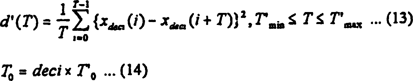
Das
abwärts
abgetastete zugeführte
akustische Signal hat beispielsweise einen Tonhöhenzyklus T (Probe), der T
minimiert, wobei die mittlere Verzerrung d' (T) durch die folgende Gleichung (7)
definiert ist. Dagegen hat das zugeführte akustische Signal s1 beispielsweise
einen Tonhöhenzyklus
T0, der durch die folgende Gleichung (8) ausgedrückt wird: For example, the downsampled input acoustic signal has a pitch cycle T (sample) that minimizes T, where the mean distortion d '(T) is defined by the following equation (7). On the other hand, the supplied acoustic signal s1 has, for example, a pitch cycle T0 expressed by the following equation (8):
Es
sei angenommen, dass das zugeführte
akustische Signal eine Abtastfrequenz von 44,1 kHz hat und dass
das abwärts
abgetastete zugeführte
akustische Signal eine Abtastfrequenz von 11,025 kHz hat. Dann gilt:
Tmax = 882, Tmin =
178, T'max =
221 und T'min = 44, wenn Tonhöhenfrequenzen im Bereich von
50 Hz bis 200 Hz gesucht werden. Das abwärts abgetastete zugeführte akustische
Signal wird verwendet, Korrelation zu erreichen. Daher ist die Datenmenge,
die zu verarbeiten ist, um den Tonhöhenzyklus zu berechnen, viel kleiner
als in dem Fall, wo der Tonhöhenzyklus
in der herkömmlichen
Vorrichtung unter Verwendung der Gleichung (1) berechnet wird.Assume that the input acoustic signal has a sampling frequency of 44.1 kHz and that the downsampled input acoustic signal has a sampling frequency of 11.025 kHz. Then, T max = 882, T min = 178, T ' max = 221, and T' min = 44 when pitch frequencies in the range of 50 Hz to 200 Hz are searched. The downsampled input acoustic signal is used to achieve correlation. Therefore, the amount of data to be processed to calculate the pitch cycle is much smaller than in the case where the pitch cycle is calculated in the conventional apparatus using equation (1).
Im
Schritt S104 liest der Prozesssteuerabschnitt 4 das zugeführte akustische
Signal s1 für
(max. Tonhöhenzyklus
Tmax × 2)
von der Prozessstartposition in den Eingangspufferabschnitt 2 über den
Verzögerungsabschnitt 10,
der die Verzögerung
D des Tiefpassfilters 7, welche dem akustischen Signal
auferlegt wird, kompensiert. Der Eingangspufferabschnitt 2 gibt
ein Signal s4 aus, oder das Signal (d), welches in 14 gezeigt ist.
Das Signal s4 wird zum Datenbetriebsabschnitt 5 übertragen.In step S104, the process control section reads 4 the supplied acoustic signal s1 for (maximum pitch cycle T max × 2) from the process start position to the input buffer section 2 over the delay section 10 , the delay D of the low-pass filter 7 , which is imposed on the acoustic signal, compensated. The input buffer section 2 outputs a signal s4, or the signal (d) which is in 14 is shown. The signal s4 becomes the data operation section 5 transfer.
Im
Schritt S105 wird bestimmt, ob die Wiedergabegeschwindigkeits-Konvertierungsrate
R größer als 1
ist. Wenn die Rate R größer als
1 ist, zeigt dies, dass die Hochgeschwindigkeitswiedergabe durchgeführt wird.
In diesem Fall läuft
der Prozesssteuerabschnitt 4 zum Schritt S106, der in 11 gezeigt
ist. Wenn die Rate R nicht größer als
1 ist, zeigt dies, dass die Niedriggeschwindigkeitswiedergabe durchgeführt wird.
Wenn dies der Fall ist, läuft
der Prozesssteuerabschnitt 4 zum Schritt S114, der in 12 gezeigt
ist.In step S105, it is determined whether the playback speed conversion rate R is greater than 1. If the rate R is greater than 1, it indicates that the high-speed reproduction is being performed. In this case, the process control section is running 4 to step S106, which is in 11 is shown. If the rate R is not greater than 1, it indicates that the low-speed reproduction is being performed. If this is the case, the process control section is running 4 to step S114, which is in 12 is shown.
Während der
Hochgeschwindigkeitswiedergabe fügt
der Datenbetriebsabschnitt 5 eine Fensterwichtung (gezeigt
in 10) im Schritt S106 unter der Steuerung des Prozesssteuerabschnitts 4 hinzu.
Die Schaltung 5 erzeugt ein 1-Tonhöhenzyklus-Schwingungsformsignal
(d. h., ein Betriebsprozesssignal s5), wie bei (e) in 14 gezeigt ist.During high-speed playback, the data operating section adds 5 a window weighting (shown in 10 ) in step S106 under the control of the process control section 4 added. The circuit 5 generates a 1-pitch cycle waveform signal (ie, an operation process signal s5) as in (e) in FIG 14 is shown.
Danach
berechnet im Schritt S107 der Prozesssteuerabschnitt 4 eine
Wiedergabesignallänge
L gemäß der folgenden
Gleichung (9): Thereafter, in step S107, the process control section calculates 4 a reproduction design length L according to the following equation (9):
Die
rechte Seite wird mit der Dezimierungsfaktorkonstante deci multipliziert.
Die Klammer ⌊⌋ in der Gleichung (9) bedeuten das
Herausfinden der größten ganzen
Zahl, welche x nicht übersteigt.
Die Wiedergabesignallänge
L ist ein Vielfaches der Dezimierungsfaktorkonstanten deci, welche
die Position der Abwärtsabtastung
betrifft.The
right side is multiplied by the decimation factor constant deci.
The bracket ⌊⌋ in the equation (9) means that
Finding out the biggest whole
Number which does not exceed x.
The playback design length
L is a multiple of the decimation factor constants deci which
the position of the downsampling
concerns.
Anschließend bestimmt
im Schritt S108 der Prozesssteuerabschnitt 4, ob die Wiedergabesignallänge länger ist
als der Tonhöhenzyklus.
Wenn dies bejaht wird, d. h., wenn die Länge länger ist als der Tonhöhenzyklus,
läuft der
Abschnitt 4 weiter zum Schritt S109. Wenn dies verneint
wird, läuft
der Abschnitt 4 weiter zum Schritt S113.Subsequently, in step S108, the process control section determines 4 whether the playback design length is longer than the pitch cycle. If this is answered in the affirmative, ie if the length is longer than the pitch cycle, the section will run 4 proceed to step S109. If this is answered in the negative, the section will run 4 proceed to step S113.
Im
Schritt S109 überträgt der Prozesssteuerabschnitt 4 eine
Ein-Tonhöhenzyklus-Schwingungsform, welche
durch den Datenbetriebsabschnitt 5 berechnet wird, über den
Eingangspufferabschnitt 2 zum Datensammlungsabschnitt 6.In step S109, the process control section transmits 4 a one-pitch cycle waveform generated by the data operation section 5 is calculated over the input buffer section 2 to the data collection section 6 ,
Dann überträgt im Schritt
S110 der Prozesssteuerabschnitt 4, um die Anzahl der Proben,
welche mit der Wiedergabesignallänge
L übertragen
werden, auszugleichen, die verbleibenden zugeführten akustischen Signale,
welche nicht zum Datenbetriebsabschnitt 5 übertragen
wurden, vom Eingangspufferabschnitt 2 zum Datensammelabschnitt 6.Then, in step S110, the process control section transmits 4 in order to equalize the number of samples transmitted with the reproduction design length L, the remaining supplied acoustic signals other than the data operation section 5 were transmitted from the input buffer section 2 to the data collection section 6 ,
Im
Schritt S111 bestimmt der Prozesssteuerabschnitt 4, ob
die Anzahl der Abtastungen, die übertragen wurden,
kleiner ist als die Wiedergabesignallänge L. Wenn dies bejaht wird,
läuft der
Abschnitt 4 weiter zum Schritt S112. Wenn dies verneint
wird, läuft
der Abschnitt 4 zum Schritt S124.In step S111, the process control section determines 4 whether the number of samples that have been transmitted is smaller than the reproduction-signal length L. If so, the section will run 4 proceed to step S112. If this is answered in the negative, the section will run 4 to step S124.
Im
Schritt S112 liest der Prozesssteuerabschnitt 4 mehrere
akustische Signale vom Datenaufzeichnungsabschnitt 1 in
den Eingangspufferabschnitt 2. Diese akustischen Signale
werden vom Eingangspufferabschnitt 2 zum Datensammlungsabschnitt 6 übertragen.
Danach läuft
der Abschnitt 4 weiter zum Schritt S124.In step S112, the process control section reads 4 a plurality of acoustic signals from the data recording section 1 in the input buffer section 2 , These acoustic signals are from the input buffer section 2 to the data collection section 6 transfer. Then the section is running 4 proceed to step S124.
Wenn
dies im Schritt S108 verneint wird, läuft der Prozesssteuerabschnitt 4 zum
Schritt S113. Im Schritt S113 überträgt der Abschnitt 4 zum
Datensammelabschnitt 6 die Proben, welche in der Ein-Tonhöhenzyklus-Schwingungsform enthalten
sind, welche durch den Datenbetriebsabschnitt 5 berechnet
wurde. Der Abschnitt 4 läuft dann weiter zum Schritt
S124. Der Schritt S124 wird später
beschrieben.If it is denied in step S108, the process control section runs 4 to step S113. In step S113, the section transmits 4 to the data collection section 6 the samples included in the one-pitch cycle waveform generated by the data operation section 5 was calculated. The section 4 then proceeds to step S124. The step S124 will be described later.
Wenn
der Schritt S105 verneinend ist, der in 10 gezeigt
ist, d. h., wenn der Prozesssteuerabschnitt 4 bestimmt,
dass die Wiedergabegeschwindigkeits-Konvertierungsrate R nicht größer als
1 ist, zeigt dies, dass die Niedriggeschwindigkeitswiedergabe gerade
durchgeführt
wird. In diesem Fall geht der Abschnitt 4 zum Schritt S114,
der in 12 gezeigt ist. Im Schritt S114
bewirkt der Abschnitt 4, dass der Datenbetriebsabschnitt 5 eine
Fensterwichtung hinzufügt,
wie in 14 gezeigt ist. Der Datenbetriebsabschnitt 5 erzeugt
ein 1-Tonhöhenzyklus-Schwingungsformsignal
(d. h., ein Betriebsprozesssignal s5), wie bei (e) in 14 gezeigt ist.If the step S105 is negative, the in 10 is shown, that is, when the process control cut 4 determines that the reproduction speed conversion rate R is not greater than 1, it indicates that the low-speed reproduction is being performed. In this case, the section goes 4 to step S114, which is in 12 is shown. In step S114, the section causes 4 in that the data operating section 5 adds a window weighting, as in 14 is shown. The data operation section 5 generates a 1-pitch cycle waveform signal (ie, an operation process signal s5) as in (e) in FIG 14 is shown.
Im
Schritt S115 wird die Länge
L des wiedergegebenen Signals gemäß der folgenden Gleichung (10) berechnet: In step S115, the length L of the reproduced signal is calculated according to the following equation (10):
Die
rechte Seite wird mit der Dezimierungsfaktorkonstante deci multipliziert.
Die Klammem ⌊⌋ in der Gleichung (10) bedeuten
das Herausfinden einer größten ganzen
Zahl, welche x nicht übersteigt.
Die Wiedergabesignallänge
L ist ein Vielfaches der Dezimierungsfaktorkonstante deci, die die
Position der Abwärtsabtastung
betrifft.The
right side is multiplied by the decimation factor constant deci.
The brackets ⌊⌋ in the equation (10) mean
finding out a whole whole
Number which does not exceed x.
The playback design length
L is a multiple of the decimation factor constant deci, which is the
Position of the downsampling
concerns.
Im
Schritt S116 wird bestimmt, ob die Wiedergabesignallänge länger ist
als (Tonhöhenzyklus × 2). Wenn
dies bejaht wird, lauft der Betrieb weiter zum Schritt S117. Wenn
dies verneint wird, läuft
der Betrieb weiter zum Schritt S122.in the
Step S116, it is determined whether the reproduction-signal length is longer
as (pitch cycle × 2). If
if it is affirmative, the operation proceeds to step S117. If
this is negated, runs
the operation proceeds to step S122.
Im
Schritt S117 überträgt der Prozesssteuerabschnitt 4 die
Schwingungsform für
den ersten Tonhöhenzyklus
vom Eingangspufferabschnitt 2 zum Datensammlungsabschnitt 6.In step S117, the process control section transmits 4 the waveform for the first pitch cycle from the input buffer section 2 to the data collection section 6 ,
Im
Schritt S118 überträgt der Prozesssteuerabschnitt 4 die
Ein-Tonhöhenzyklus-Schwingungsform, welche
im Datenbetriebsabschnitt 5 berechnet wurde, zum Datensammlungsabschnitt 6.In step S118, the process control section transmits 4 the one-pitch cycle waveform used in the data operation section 5 was calculated to the data collection section 6 ,
Dann überträgt im Schritt
S119 der Prozesssteuerabschnitt 4 die zugeführten akustische
Signale, welche nicht zum Abschnitt 6 im Schritt S117 übertragen
wurden, vom Eingangspufferabschnitt 2 zum Datensammlungsabschnitt 6, so
dass die Anzahl der übertragenen
Proben die Länge
L des Wiedergabesignals definieren kann.Then, in step S119, the process control section transmits 4 the supplied acoustic signals, which does not go to the section 6 in step S117, from the input buffer section 2 to the data collection section 6 such that the number of samples transmitted can define the length L of the playback signal.
Im
Schritt S120 bestimmt der Prozesssteuerabschnitt 4, ob
die Anzahl der übertragenen
Proben kürzer
ist als die Länge
L des wiedergegebenen Signals. Wenn dies bejaht wird, läuft der
Abschnitt 4 weiter zum Schritt S121. Wenn dies verneint
wird, läuft
der Abschnitt 4 weiter zum Schritt S124.In step S120, the process control section determines 4 whether the number of transmitted samples is shorter than the length L of the reproduced signal. If yes, the section will run 4 proceed to step S121. If this is answered in the negative, the section will run 4 proceed to step S124.
Im
Schritt S121 liest der Prozesssteuerabschnitt 4 mehr akustisches
Signal vom Datenaufzeichnungsabschnitt 1 in den Eingangspufferabschnitt 2 und überträgt diese
Proben zum Datensammlungsabschnitt 6. Der Abschnitt 4 läuft dann
weiter zum Schritt S124.In step S121, the process control section reads 4 more acoustic signal from the data logging section 1 in the input buffer section 2 and transmits these samples to the data collection section 6 , The section 4 then proceeds to step S124.
Im
Schritt S122 überträgt der Prozesssteuerabschnitt 4 die
Schwingungsform für
den ersten Tonhöhenzyklus
vom Eingangspufferabschnitt 2 zum Datensammlungsabschnitt 6.In step S122, the process control section transmits 4 the waveform for the first pitch cycle from the input buffer section 2 to the data collection section 6 ,
Im
Schritt S123 überträgt der Prozesssteuerabschnitt 4 zum
Datensammlungsabschnitt 6 die Abtastungen (d. h., Wiedergabesignallänge L-Tonhöhenzyklus
T0), welche in der Ein-Tonhöhenzyklus-Schwingungsform
enthalten sind, welche im Datenbetriebsabschnitt 5 berechnet
wurde. Dann läuft
der Abschnitt 4 weiter zum Schritt S124.In step S123, the process control section transmits 4 to the data collection section 6 the samples (ie, reproduction design length L pitch cycle T0) included in the one-pitch cycle waveform which are in the data operation section 5 was calculated. Then the section is running 4 proceed to step S124.
Im
Schritt S124 aktualisiert der Prozesssteuerabschnitt 4 die
nächste
Prozessstartposition P' gemäß der folgenden
Gleichung (11): In step S124, the process control section updates 4 the next process start position P 'according to the following equation (11):
In
der Gleichung (11) ist ΔP
der Bewegungsabstand von der Prozessstartposition. Der Abstand ΔP wird durch
die folgende Gleichung (12) angegeben: In the equation (11), ΔP is the moving distance from the process start position. The distance ΔP is given by the following equation (12):
Die
nächste
Prozessstartposition P' wird
aktualisiert, so dass sie sich zur äußersten Abwärtsabtastposition bewegen kann.The
next
Process start position P 'is
updated so that it can move to the extreme down-sampling position.
Im
Schritt S125 wird bestimmt, ob der Prozess beendet wurde oder nicht.
Wenn dies verneint wird, geht der Betrieb weiter zum Schritt S102.
Wenn dies bejaht wird, wird der Prozess beendet.in the
Step S125 determines whether the process has ended or not.
If this is answered in the negative, the operation proceeds to step S102.
If yes, the process is terminated.
Es
wurde die erste Ausführungsform
der vorliegenden Erfindung beschrieben.It
became the first embodiment
of the present invention.
Die
zweite Ausführungsform
der Erfindung wird nun beschrieben. Die zweite Ausführungsform
ist eine Vorrichtung, welche die Geschwindigkeit zum Wiedergeben
digitaler akustischer PCM-Signale umsetzt. Die zweite Ausführungsform
ist jedoch dazu bestimmt, einen Rahmenprozess durchzuführen, und
nicht einen Prozess, der bei der ersten Ausführungsform, die in 9 gezeigt
ist, ausgeführt
wird. Das heißt,
die zweite Ausführungsform
verarbeitet zugeführte
akustische Signale und akustische Ausgangssignale in Einheiten,
welche jeweils aus einer vorgeschriebenen Anzahl von Signalen bestehen.The second embodiment of the invention will now be described. The second embodiment is a device that converts the speed for reproducing digital PCM acoustic signals. However, the second embodiment is intended to perform a frame process, not a process similar to that in the first embodiment described in FIG 9 is shown executed. That is, the second embodiment processes supplied acoustic signals and output acoustic signals in units each consisting of a prescribed number of signals.
15 zeigt
die zweite Ausführungsform,
d. h., eine Wiedergabegeschwindigkeits-Konvertierungsvorrichtung.
Die Vorrichtung weist einen Datenaufzeichnungsabschnitt 1,
einen Tonhöhenberechnungsabschnitt 3,
ein Tiefpassfilter 7, einen Dezimierungsabschnitt 8,
und einen Signalpufferabschnitt 9 auf. Der Datenaufzeichnungsabschnitt 1 zeichnet
akustische Signale auf und hält
diese. Das Tiefpassfilter 7 unterdrückt die Hochbandkomponente
jeden akustischen Signals, welches im Datenaufzeichnungsabschnitt 1 aufgezeichnet ist.
Der Dezimierungsabschnitt 8 führt einen geeigneten Dezimierungsprozess
in Bezug auf das Ausgangssignal vom Tiefpassfilter 7 durch.
Der Signalpufferabschnitt 9 sammelt die akustischen Signale,
welche durch den Dezimierungsabschnitt 8 abwärts abgetastet
sind, in Einheiten von Rahmen. Der Abschnitt 3 berechnet den
Tonhöhenzyklus
jeden Signals, welches im Signalpufferabschnitt 9 gehalten
wird. 15 shows the second embodiment, that is, a playback speed conversion device. The device has a data recording section 1 a pitch calculation section 3 , a low pass filter 7 , a decimation section 8th , and a signal buffer section 9 on. The data recording section 1 Records and holds acoustic signals. The low pass filter 7 suppresses the high band component of each acoustic signal which is in the data recording section 1 is recorded. The decimation section 8th performs an appropriate decimation process with respect to the output signal from the low-pass filter 7 by. The signal buffer section 9 collects the acoustic signals which pass through the decimation section 8th down sampled, in units of frames. The section 3 calculates the pitch cycle of each signal in the signal buffer section 9 is held.
Die
Wiedergabegeschwindigkeits-Konvertierungsvorrichtung weist außerdem einen
Eingangspufferabschnitt 2, einen Datenbetriebsabschnitt 5,
einen Verzögerungsabschnitt 10,
einen Datenposition-Bezeichnungsabschnitt 11 und einen
Rahmendaten-Sammelabschnitt 12 auf. Der Verzögerungsabschnitt 10 kompensiert
die Verzögerung
D des Tiefpassfilters 7, die bei dem akustischen Signal
vorhanden ist. Der Eingangspufferabschnitt 2 sammelt die
akustischen Signale in Rahmeneinheiten, welche zu ihm über den
Verzögerungsabschnitt 10 geliefert
werden. Der Datenbetriebsabschnitt 5 berechnet eine ähnliche
Schwingungsform von der Tonhöhenzyklus-Schwingungsform,
welche der Tonhöhenberechnungsabschnitt 3 berechnet
hat. Der Rahmendaten-Sammelabschnitt 12 (ein Ausgangsrahmen-Pufferabschnitt)
sammelt die Daten in Rahmeneinheiten, welche durch den Datenbetriebsabschnitt 5 berechnet
wurden. Der Datenpositions- Bestimmungsabschnitt 11 bestimmt
die Position, wo der Eingangspufferabschnitt 2 akustische
Signale liefert, die Position, wo die Berechnung des Tonhöhenzyklus
im Eingangspufferabschnitt 2 begonnen wurde, die Position,
wo die Daten zum Rahmendaten-Sammelabschnitt 12 übertragen
werden, und die Positionsdaten, welche im Rahmendaten-Sammelabschnitt 12 aufgezeichnet
wurden.The playback speed conversion device also has an input buffer section 2 , a data operating section 5 , a delay section 10 , a data position designation section 11 and a frame data collection section 12 on. The delay section 10 compensates for the delay D of the low-pass filter 7 which is present at the acoustic signal. The input buffer section 2 collects the acoustic signals in frame units which are to it via the delay section 10 to be delivered. The data operation section 5 calculates a similar waveform from the pitch cycle waveform, which the pitch calculating section 3 calculated. The frame data collection section 12 (an output frame buffer section) collects the data in frame units transmitted by the data operation section 5 were calculated. The data position determination section 11 determines the position where the input buffer section 2 provides acoustic signals, the position where the calculation of the pitch cycle in the input buffer section 2 was started, the position where the data to frame data collection section 12 are transferred, and the position data, which in the frame data collecting section 12 were recorded.
Die
Arbeitsweise der Wiedergabegeschwindigkeits-Umsetzungsvorrichtung, d. h., die zweite
Ausführungsform
der Erfindung, wird kurz beschrieben.The
Operation of the playback speed conversion device, i. h., the second
embodiment
of the invention will be briefly described.
Von
den akustischen Signalen, welche im Datenaufzeichnungsabschnitt 1 gehalten
werden, wird das zugeführte
akustische Signal s1 für
einen Eingangsrahmen zum Tiefpassfilter 7 geliefert. Das
Tiefpassfilter 7 unterdrückt die Hochbandkomponente
des akustischen Signals s1. Der Dezimierungsabschnitt 8 führt geeignete
Abwärtsabtastung
in Bezug auf das Signal durch, welches vom Tiefpassfilter 7 ausgegeben
wird. Das vom Abschnitt 8 ausgegebene Signal wird in den
Signalpufferabschnitt 9 gelesen.Of the acoustic signals included in the data recording section 1 are held, the supplied acoustic signal s1 for an input frame to the low-pass filter 7 delivered. The low pass filter 7 suppresses the high band component of the acoustic signal s1. The decimation section 8th performs appropriate downsampling on the signal coming from the low pass filter 7 is issued. That from the section 8th output signal is in the signal buffer section 9 read.
Das
zugeführte
akustische Signal s1 für
den Eingangsrahmen wird vom Datenaufzeichnungsabschnitt 1 zum
Verzögerungsabschnitt 10 geliefert,
der die Verzögerung
D des Tiefpassfilters 7, der das akustische Signal s1 ausgesetzt
ist, kompensiert. Das Signal, welches vom Verzögerungsabschnitt 10 ausgegeben
wird, wird in den Eingangspufferabschnitt 2 gelesen.The input acoustic signal s1 for the input frame is acquired from the data recording section 1 to the delay section 10 supplied, the delay D of the low-pass filter 7 , which is exposed to the acoustic signal s1, compensated. The signal coming from the delay section 10 is output is in the input buffer section 2 read.
Ein
abwärts
abgetastetes zugeführtes
akustisches Signal s2 die meisten 2 Tonhöhenzyklen von der Prozessstartposition,
welche durch den Datenpositions-Bezeichnungsabschnitt 11 bestimmt
wird, wird vom Signalpufferabschnitt 9 zum Tonhöhenberechnungsabschnitt 3 übertragen.
Der Abschnitt 3 berechnet einen Tonhöhenzyklus s3.A downsampled input acoustic signal s2 most 2 pitch cycles from the process start position indicated by the data position designation section 11 is determined is the signal buffer section 9 to the pitch calculation section 3 transfer. The section 3 calculates a pitch cycle s3.
Der
Datenposition-Bestimmungsabschnitt 11 erzeugt ein Signal
s4 vom Tonhöhenzyklus
s3, der durch die Tonhöhenberechnungsabschnitt 3 berechnet
wurde. Das Signal s4 wird vom Eingangspufferabschnitt 2 zum
Datenbetriebsabschnitt 5 übertragen.The data position determination section 11 generates a signal s4 from the pitch cycle s3 inputted by the pitch calculation section 3 was calculated. The signal s4 is from the input buffer section 2 to the data operating section 5 transfer.
Der
Datenbetriebsabschnitt 5 berechnet eine ähnliche
Schwingungsform von der Tonhöhenzyklus-Schwingungsform,
wobei ein Betriebsprozesssignal s5 erzeugt wird. Das Betriebsprozesssignal
s5 wird geeignet in den Eingangspufferabschnitt 2 überschrieben.The data operation section 5 calculates a similar waveform from the pitch cycle waveform, generating an operation process signal s5. The operation process signal s5 becomes suitable in the input buffer section 2 overwritten.
Das
akustische Ausgangssignal für
die Ausgangsrahmenlänge,
welche von der Übertragungsposition gemessen
wurde, welche durch den Datenpositions-Bestimmungsabschnitt 11 bestimmt
wird, wird vom Eingangspufferabschnitt 2 zum Rahmendaten-Sammelabschnitt 12 übertragen.The acoustic output signal for the output frame length measured from the transfer position given by the data position determining section 11 is determined is from the input buffer section 2 to the frame data collection section 12 transfer.
Der
Datenpositions-Bestimmungsabschnitt 11 aktualisiert geeignet
die nächste
Prozessstartposition P' im
Eingangspufferabschnitt 2.The data position determination section 11 appropriately updates the next process start position P 'in the input buffer section 2 ,
Wie
die Wiedergabegeschwindigkeits-Konvertierungsvorrichtung, d. h.,
die zweite Ausführungsform, die
oben beschrieben wurde, arbeitet, wird ausführlich nun mit Hilfe der Flussdiagramme
von 16, 17, 18, 19 und 20 erläutert.How the reproduction speed conversion device, that is, the second embodiment described above operates will now be described in detail with reference to the flowcharts of FIG 16 . 17 . 18 . 19 and 20 explained.
Zunächst wird
im Schritt S201 die Vorrichtung initialisiert, wobei die folgenden
Einstellungen getroffen werden:
Ausgangsflag = 0
Eingangsflag
= 1
Eingangsposition s8 = 0
Übertragungsposition s9 = 0
Prozessstartposition
s10 = 0
Aufzeichnungsposition s11 = 0.First, in step S201, the device is initialized, with the following settings being made:
Output flag = 0
Input flag = 1
Input position s8 = 0
Transfer position s9 = 0
Process start position s10 = 0
Recording position s11 = 0.
Die
Werte für
die Eingangsposition, die Prozessstartposition, die Übertragungsposition
und die Aufzeichnungsposition werden durch den Datenpositions-Bestimmungsabschnitt 11 gesteuert,
der in 15 gezeigt ist.The values for the input position, the process start position, the transfer position, and the recording position are set by the data position determination section 11 controlled in 15 is shown.
Im
Schritt S202 bestimmt der Datenpositions-Bestimmungsabschnitt 11,
ob das Ausgangsflag 1 ist oder nicht. Wenn dies bejaht
wird, läuft
der Betrieb zum Schritt S203. Wenn dies verneint wird, läuft der
Betrieb zum Schritt S206.In step S202, the data position determination section determines 11 , whether the exit flag 1 is or not. If affirmative, the operation goes to step S203. If it is answered in the negative, the operation goes to step S206.
Im
Schritt S203 steuert der Datenpositions-Bestimmungsabschnitt 11 den
Rahmendaten-Sammelabschnitt 12 (d. h., den Ausgangsrahmen-Pufferabschnitt),
der in 15 gezeigt ist. Der Abschnitt 12 gibt
die akustischen Signale in Rahmeneinheiten aus. Danach aktualisiert
im Schritt S204 der Datenpositions-Bestimmungsabschnitt 11 das
Ausgangsflag auf "0".In step S203, the data position determination section controls 11 the frame data collection section 12 (ie, the output frame buffer section) included in 15 is shown. The section 12 outputs the acoustic signals in frame units. Thereafter, in step S204, the data position determination section is updated 11 the exit flag to "0".
Im
Schritt S205 bestimmt der Datenpositions-Bestimmungsabschnitt 11,
ob der Prozess beendet wurde oder nicht. Wenn dies bejaht wird,
wird der Prozess beendet. Wenn dies verneint wird, läuft der
Betrieb zum Schritt S202.In step S205, the data position determination section determines 11 whether the process has ended or not. If yes, the process is terminated. If not, the operation goes to step S202.
Wie
oben beschrieben läuft
der Betrieb zum Schritt S206, wenn der Datenpositions-Bestimmungsabschnitt 11 im
Schritt S202 bestimmt, dass das Ausgangsflag nicht 1 ist. Im Schritt
S206 wird bestimmt, ob das Eingangsflag 1 ist.As described above, the operation proceeds to step S206 when the data position determination section 11 In step S202, it is determined that the output flag is not 1. In step S206, it is determined whether the input flag 1 is.
Wenn
dies im Schritt S206 bejaht wird, läuft der Betrieb zum Schritt
S207. Wenn dies verneint wird, läuft
der Betrieb zum Schritt S210, der in 17 gezeigt
ist.If affirmative in step S206, the operation proceeds to step S207. If this is negated, the operation goes to step S210 which is in 17 is shown.
Im
Schritt S207 wird das zugeführte
akustische Signal s1 für
die zugeführte
Rahmenlänge
vom Datenaufzeichnungsabschnitt 1 über den Verzögerungsabschnitt 10 in
den Eingangspufferabschnitt 2 unter der Steuerung des Datenpositions-Bestimmungsabschnitts 11 gelesen.
Genauer ausgedrückt
wird das Signal s1 auf die Position im Eingangspufferabschnitt 2 gelesen,
die bezeichnet wird durch "Eingangsposition
s8".In step S207, the supplied acoustic signal s1 for the supplied frame length from the data recording section 1 over the delay section 10 in the input buffer section 2 under the control of the data position determination section 11 read. More specifically, the signal s1 becomes the position in the input buffer section 2 read, which is denoted by "input position s8".
Danach
wird im Schritt S208 das zugeführte
akustische Signal s1 der Eingangsrahmenlänge vom Datenleseabschnitt 1 unter
der Steuerung des Datenposition-Bestimmungsabschnitts 11 gelesen.
Das Signal s1 wird zum Tiefpassfilter 7 geliefert, welches
Tiefpassfilterung in Bezug auf das Signal s1 durchführt. Das
vom Tiefpassfilter 7 ausgegebene Signal wird im Dezimierungsabschnitt 8 einer
Abwärtsabtastung
unterworfen. Das Signal, welches vom Dezimierungsabschnitt 8 ausgegeben
wird, wird in den Signalpufferabschnitt 9 gelesen.Thereafter, in step S208, the input acoustic signal s1 of the input frame length from the data read section 1 under the control of the data position determination section 11 read. The signal s1 becomes the low-pass filter 7 which performs low-pass filtering with respect to the signal s1. The from the Low Pass Filter 7 output signal is in the decimation section 8th subjected to a downsampling. The signal coming from the decimation section 8th is output is in the signal buffer section 9 read.
Im
Schritt S209 aktualisiert der Datenpositions-Bestimmungsabschnitt 11 die
Eingangsposition s8 auf (Eingangsposition s8) + (Eingangsrahmenlänge).In step S209, the data position determination section updates 11 the input position s8 on (input position s8) + (input frame length).
Danach
bestimmt im Schritt S210, der in 17 gezeigt
ist, der Datenpositions-Bestimmungsabschnitt 11, ob die
Eingangsposition s8 größer ist
als die Prozessstartposition s10. Wenn dies bejaht wird, läuft der
Betrieb zum Schritt S211. Wenn dies verneint wird, läuft der
Betrieb zum Schritt S215.Thereafter, in step S210, determined in 17 is shown, the data position determination section 11 whether the input position s8 is greater than the process start position s10. If affirmative, the operation goes to step S211. If this is negated, the operation goes to step S215.
Im
Schritt S211 bestimmt der Datenpositions-Bestimmungsabschnitt 11,
ob (Ausgangsrahmenlänge) – (Aufzeichnungsposition
s11) gleich oder kleiner ist als (Prozessstartposition s10) – (Übertragungsposition s9).
Wenn dies bejaht wird, läuft
der Betrieb zum Schritt S212. Wenn dies verneint wird, läuft der
Betrieb zum Schritt S226.In step S211, the data position determination section determines 11 whether (output frame length) - (recording position s11) is equal to or smaller than (process start position s10) - (transfer position s9). If affirmative, the operation goes to step S212. If not, the operation goes to step S226.
Im
Schritt S212, der in 17 gezeigt ist, werden Signale
an der Position im Eingangspufferabschnitt 2, welche durch "Übertragungsposition s9" bezeichnet ist,
zum Rahmendaten-Sammelabschnitt (Ausgangsrahmen-Pufferabschnitt) 12 übertragen,
bis der Abschnitt 12 voll wird, welche mit "Aufzeichnungsposition
s11" wurde.In step S212, which is in 17 are shown, signals at the position in the input buffer section 2 indicated by "transfer position s9" to the frame data collection section (output frame buffer section) 12 transfer until the section 12 becomes full, which became "record position s11".
Im
Schritt S213 wird ein Pufferverschiebungsprozess in Bezug auf die
akustischen Signale durchgeführt,
welche im Eingangspufferabschnitt 2 und im Signalpufferabschnitt 9 gehalten
werden, wobei diese Signale um einen vorgeschriebenen "Pufferverschiebungsbetrag" verschoben werden,
wie in 22 gezeigt ist. Der "Pufferverschiebungsbetrag" ist ein Wert, welcher
durch eine Dezimierungsfaktorkonstante geteilt werden kann, die
annähernd
gleich der "Eingangsrahmenlänge" ist, ohne irgendeinen
Rest zu lassen.In step S213, a buffer shifting process is performed on the acoustic signals received in the input buffer section 2 and in the signal buffer section 9 these signals are shifted by a prescribed "buffer shift amount" as shown in FIG 22 is shown. The "buffer shift amount" is a value that can be divided by a decimation factor constant that is approximately equal to the "input frame length" without leaving any remainder.
Der
Pufferverschiebeprozess wird ausführlich mit Hilfe von 18 und 22 beschrieben.The buffer shifting process is described in detail using 18 and 22 described.
Zunächst bestimmt
im Schritt S222, der in 18 gezeigt
ist, der Datenpositions-Bestimmungsabschnitt 11, ob die Übertragungsposition
s9 gleich oder größer ist
als der Pufferverschiebebetrag. Wenn dies bejaht wird, läuft der
Betrieb weiter zum Schritt S223. Wenn dies verneint wird, wird der
Pufferverschiebeprozess beendet.First, in step S222, determined in 18 is shown, the data position determination section 11 Whether the transfer position s9 is equal to or greater than the buffer shift amount. If affirmative, the operation proceeds to step S223. If this is answered in the negative, the buffer shifting process is ended.
Im
Schritt S223 bestimmt die Datenpositions-Bestimmungsabschnitt 11,
ob die Prozessstartposition s10 größer ist als (max. Tonhöhenzyklus)
+ (Pufferverschiebebetrag). Wenn dies bejaht wird, läuft der
Betrieb zum Schritt S224. Wenn dies verneint wird, ist der Pufferverschiebeprozess
beendet.In step S223, the data position determination section determines 11 Whether the process start position s10 is greater than (maximum pitch cycle) + (buffer shift amount). If affirmative, the operation goes to step S224. If this is answered in the negative, the buffer shifting process is ended.
Im
Schritt S224 bewegt, wie in 22 gezeigt
ist, der Datenpositions-Bestimmungsabschnitt 11 die akustischen
Signale im Eingangspufferabschnitt 2 um einen Abstand äquivalent
dem Pufferschiebebetrag, und die akustischen Signale im Signalpufferabschnitt 9 um
einen Abstand äquivalent
zu (Pufferverschiebebetrag/Dezimierungsfaktor).In step S224 moves as in 22 is shown, the data position determination section 11 the acoustic signals in the input buffer section 2 by a distance equivalent to the buffer shift amount, and the acoustic signals in the signal buffer section 9 by a distance equivalent to (buffer shift amount / decimation factor).
Im
Schritt S225 aktualisiert der Datenpositions-Bestimmungsabschnitt 11 die
Datenpositionen wie folgt:
Eingangsposition s8 = Eingangsposition
s8 – Pufferverschiebebetrag
Übertragungsposition
s9 = Übertragungsposition
s9 – Pufferverschiebebetrag
Prozessstartposition
s10 = Prozessstartposition s10 – PufferverschiebebetragIn step S225, the data position determination section updates 11 the data items as follows:
Input position s8 = input position s8 - buffer shift amount
Transfer position s9 = transfer position s9 - buffer shift amount
Process start position s10 = process start position s10 - buffer shift amount
Der
Pufferverschiebeprozess wurde nunmehr beschrieben.Of the
Buffer shift process has now been described.
Wiederum
in Bezug auf 17 setzt im Schritt S214 die
Datenpositions-Bestimmungsabschnitt 11 die Aufzeichnungsposition
s11 auf "0", das Ausgangsflag
auf "1" und das Eingangsflag
auf "0". Dann läuft der
Abschnitt 11 weiter zum Schritt S202.Again in terms of 17 sets the data position determination section in step S214 11 the recording position s11 to "0", the output flag to "1" and the input flag to "0". Then the section is running 11 proceed to step S202.
Im
Schritt S215 bestimmt der Datenposition-Bestimmungsabschnitt 11,
ob (Eingangsrahmenlänge) – (Aufzeichnungsposition
s11) kleiner ist als (Eingangsposition s8) – (Übertragungsposition s9). Wenn
dies bejaht wird, läuft
der Betrieb zum Schritt S216. Wenn dies verneint wird, läuft der
Betrieb zum Schritt S219.In step S215, the data position determination section determines 11 whether (input frame length) - (recording position s11) is smaller than (input position s8) - (transmission position s9). If affirmative, the operation goes to step S216. If this is negated, the operation goes to step S219.
Im
Schritt S216 werden, wie in 23 gezeigt
ist, akustische Signale an der Position im Eingangspufferabschnitt 2,
welche durch "Übertragungsposition
s9" bezeichnet sind,
zum Ausgangsrahmen-Pufferabschnitt 12 übertragen, bis der Abschnitt 12 voll
wird, von der Position im Abschnitt 12, welche als "Leseposition s11" bezeichnet wurde.
Dann wird im Schritt S217 der Pufferverschiebeprozess, der oben
beschrieben wurde, ausgeführt.In step S216, as in FIG 23 is shown, acoustic signals at the position in the Eingangspuf ferabschnitt 2 , which are denoted by "transfer position s9", to the output frame buffer section 12 transfer until the section 12 becomes full, from the position in the section 12 , which has been referred to as "reading position s11". Then, in step S217, the buffer shifting process described above is executed.
Im
Schritt S218 legt der Datenpositions-Bestimmungsabschnitt 11 die
Aufzeichnungsposition auf "0" fest, das Ausgangsflag
auf "1", und das Eingangsflag "0". Der Abschnitt 11 läuft weiter
zum Schritt S202, der in 16 gezeigt
ist.In step S218, the data position determination section sets 11 the recording position is "0", the output flag is "1", and the input flag is "0". The section 11 proceeds to step S202 which is in 16 is shown.
Wie
oben beschrieben läuft
der Betrieb zum Schritt S219, wenn die Antwort im Schritt S215 verneinend
ist. Im Schritt S219 wird, wie in 24 gezeigt
ist, das akustische Signal an der Position, welche durch "Eingangsposition
s8" bezeichnet wird,
von der Position im Eingangspufferabschnitt 2, der durch "Übertragungsposition s9" bezeichnet wird,
zur Position im Ausgangsrahmenpufferabschnitt 12 übertragen,
der durch "Aufzeichnungsposition
s11" bezeichnet
wird. Dann wird im Schritt S220 die oben erwähnte Pufferverschiebeverarbeitung
ausgeführt.As described above, if the answer in step S215 is negative, the operation proceeds to step S219. In step S219, as in FIG 24 is shown, the acoustic signal at the position, which is designated by "input position s8", from the position in the input buffer section 2 indicated by "transfer position s9" to the position in the output frame buffer section 12 transmitted by "record position s11". Then, in step S220, the above-mentioned buffer shift processing is executed.
Im
Schritt S221 werden das Ausgangsflag und das Eingangsflag auf "0" bzw. "1" eingestellt.
Der Betrieb läuft
zum Schritt S202, der in 16 gezeigt
ist, weiter.In step S221, the output flag and the input flag are set to "0" and "1", respectively. The operation goes to step S202 which is in 16 is shown, continue.
Dann
werden im Datenpositions-Bestimmungsabschnitt 11 im Schritt
S226, der in 19 gezeigt ist, das akustische
Signal an der Position, welche mit "Prozessstartposition s10" bezeichnet ist,
von der Position im Eingangspufferabschnitt 2, der in 25 gezeigt
ist, welche mit "Übertragungsposition
s9" bezeichnet ist, zur
Position im Ausgangsrahmen-Pufferabschnitt 12 übertragen,
der mit "Aufzeichnungsposition
s11" bezeichnet
ist.Then in the data position determination section 11 in step S226, which is in 19 2, the acoustic signal at the position indicated by "process start position s10" is shown from the position in the input buffer section 2 who in 25 shown as "transfer position s9" to the position in the output frame buffer section 12 transmitted, which is designated "recording position s11".
Im
Schritt S227 wird der oben erwähnte
Pufferverschiebeprozess ausgeführt.
Der Betrieb läuft
zum Schritt S228, in welchem bestimmt wird, ob die Wiedergabegeschwindigkeits-Umsetzungsrate
R größer als
1 ist. Wenn die Rate R größer als
1 ist, läuft
der Betrieb weiter zu den Schritten S229 usw., welche während des Hochgeschwindigkeitswiedergabeprozesses
durchgeführt
werden. Wenn die Rate R nicht größer als
1 ist, läuft der
Betrieb zum Schritt S236, der in 20 gezeigt
ist. Die Prozesse, welche während
der Hochgeschwindigkeitswiedergabe ausgeführt werden, d. h., die Schritte
S229 usw., werden mit Hilfe von 26 erläutert.In step S227, the above-mentioned buffer shift process is executed. The operation proceeds to step S228, where it is determined whether the playback speed conversion rate R is greater than 1. If the rate R is greater than 1, the operation proceeds to the steps S229, etc., which are performed during the high-speed reproduction process. If the rate R is not greater than 1, the operation goes to step S236 which is in 20 is shown. The processes which are executed during the high-speed reproduction, that is, the steps S229, etc., are determined by means of 26 explained.
Im
Schritt S229 bestimmt der Datenpositions-Bezeichnungsabschnitt 11,
ob (Eingangsposition s8) – (Prozessstartposition
s10) größer ist
als 2 × (maximaler
Tonhöhenzyklus).
Wenn dies bejaht wird, läuft
der Abschnitt 11 weiter zum Schritt S230. Wenn dies verneint
wird, läuft
der Abschnitt 11 zum Schritt S243. Im Schritt S243 stellt
der Datenpositions-Bezeichnungsabschnitt 11 das Ausgangsflag
und das Eingangsflag auf "0" bzw. "1" ein. Dann läuft der Abschnitt 11 weiter
zum Schritt S202, der in 16 gezeigt
ist.In step S229, the data position designation section determines 11 whether (input position s8) - (process start position s10) is greater than 2 × (maximum pitch cycle). If yes, the section will run 11 proceed to step S230. If this is answered in the negative, the section will run 11 to step S243. In step S243, the data position designation section 11 the output flag and the input flag to "0" and "1", respectively. Then the section is running 11 proceed to step S202, which is in 16 is shown.
Danach
berechnet im Schritt S230 der Tonhöhenberechnungsabschnitt 3 den
Tonhöhenzyklus
an der Position, welche durch "Prozessstartposition
s10" bezeichnet
wird, von dem akustischen Signal, welches vom Signalpufferabschnitt 9 unter
der Steuerung der Datenpositions-Bezeichnungsabschnitt 11 extrahiert
wurde. Beispielsweise berechnet der Abschnitt 3 einen Tonhöhenzyklus
T (= T'0), der die
mittlere Verzerrung d' (T) minimieren
wird, welche durch die folgende Gleichung (13) definiert ist, für das akustische
Signal xdeci(i) (0 < i < 2 × T'max),
welches im Signalpufferabschnitt 9 gehalten wird, an der
Position, welche durch "Prozessstartposition
s10" bezeichnet
wird. Dann erhält
der Abschnitt 3 den Tonhöhenzyklus T0 gemäß der folgenden
Gleichung (14).Thereafter, in step S230, the pitch calculating section calculates 3 the pitch cycle at the position indicated by "process start position s10" from the acoustic signal output from the signal buffer section 9 under the control of the data position designation section 11 was extracted. For example, the section calculates 3 a pitch cycle T (= T'0) which will minimize the mean distortion d '(T) defined by the following equation (13) for the acoustic signal x deci (i) (0 <i <2 x T ' max ), which in the signal buffer section 9 is held at the position indicated by "process start position s10". Then get the section 3 the pitch cycle T0 according to the following equation (14).
Im
Schritt S231 bestimmt der Datenpositions-Bezeichnungsabschnitt 11,
ob der Tonhöhenzyklus,
der im Schritt S230 berechnet wurde, gültig ist oder nicht. Wenn der
Tonhöhenzyklus
als gültig
gefunden wird, läuft der
Betrieb zum Schritt S232. Wenn der Tonhöhenzyklus als nicht gültig gefunden
wird, lauft der Betrieb zum Schritt S245, der in 20 gezeigt
ist.In step S231, the data position designation section determines 11 Whether the pitch cycle calculated in step S230 is valid or not. If the pitch cycle is found to be valid, the operation proceeds to step S232. If the pitch cycle is found not valid, the operation proceeds to step S245 which is in 20 is shown.
Im
Schritt S232 überträgt der Datenpositions-Bezeichnungsabschnitt 11 das
akustische Signal für
2 Tonhöhenzyklen
als Betriebsprozesssignal s4 vom Eingangspufferabschnitt 2 zum
Datenbetriebsabschnitt 5.In step S232, the data position designation section transmits 11 the acoustic signal for 2 pitch cycles as operating process signal s4 from the input buffer section 2 to the data operating section 5 ,
Im
Schritt S233 steuert der Datenpositions-Bezeichnungsabschnitt 11 den
Datenbetriebsabschnitt 5. Der Abschnitt 5 fügt eine
Fensterwichtung dem Signal s4 hinzu, wobei eine Schwingungsform
für einen
Tonhöhenzyklus
erzeugt wird. Die somit erzeugte Schwingungsform wird zur Position
im Eingangspufferabschnitt 2 übertragen, welche durch (Prozessstartposition
s10) + (Tonhöhenzyklus)
bezeichnet ist.In step S233, the data position designating section controls 11 the data operating section 5 , The section 5 adds a window weighting to signal s4, generating a waveform for a pitch cycle. The waveform thus generated becomes the position in the input buffer section 2 transmitted by (process start position s10) + (pitch cycle).
Im
Schritt S234 wird die Übertragungsposition
s9 auf (Prozessstartposition) + (Tonhöhenzyklus) aktualisiert. Der
Betrieb läuft
weiter zum Schritt S235.in the
Step S234 becomes the transfer position
s9 is updated to (process start position) + (pitch cycle). Of the
Operation is running
proceed to step S235.
Wenn
im Schritt S228 bestimmt wird, dass die Wiedergabegeschwindigkeits-Umsetzungsrate
R größer ist
als 1, und im Schritt S236 (20) bestimmt
wird, dass die Rate R kleiner ist als 1, läuft der Betrieb weiter zum
Prozess der Niedriggeschwindigkeitswiedergabe (Schritt S237 usw.).
Ansonsten läuft
der Betrieb zum Schritt S245.If it is determined in step S228 that the reproduction speed conversion rate R is greater than 1, and in step S236 (FIG. 20 ) is determined that the rate R is less than 1, the operation proceeds to the process of low-speed reproduction (step S237, etc.). Otherwise, the operation goes to step S245.
Im
Schritt S237 kann der Datenpositions-Bezeichnungsabschnitt 11 bestimmen,
dass (Eingangsposition s8) – (Prozessstartposition
s10) größer ist
als der maximale Tonhöhenzyklus.
Wenn dies so ist, läuft
der Abschnitt 11 zum Schritt S238. Wenn dies nicht so ist,
läuft der
Abschnitt 11 zum Schritt S243, der in 19 gezeigt
ist. Im Schritt S243 setzt der Abschnitt 11 das Ausgangsflag
bzw. das Eingangsflag auf "0" bzw. "1", und geht weiter zu den Schritten S202.In step S237, the data position designation section 11 determine that (input position s8) - (process start position s10) is greater than the maximum pitch cycle. If so, the section will run 11 to step S238. If not, the section will run 11 to step S243, which is in 19 is shown. In step S243, the section sets 11 the output flag is "0" or "1", and proceeds to step S202.
Im
Schritt S238 wird der Tonhöhenzyklus
an der Position, welche durch" Prozessstartposition
s10" bezeichnet
ist, von dem akustischen Signal berechnet, welches im Signalpufferabschnitt 9 extrahiert
wird. Beispielsweise wird ein Tonhöhenzyklus T (= T'0) berechnet, der
die mittlere Verzerrung d' (T)
minimieren wird, definiert durch die folgende Gleichung (15), für das akustische
Signal xdeci(i) (0 < i < 2 × T'max),
welches im Signalpufferabschnitt 9 gehalten wird, an der
Position, die durch "Prozessstartposition
s10" bezeichnet
wird. Dann wird der Tonhöhenzyklus
T0 gemäß der folgenden
Gleichung (16) erlangt. In der Gleichung (16) ist deci eine Dezimierungsfaktorkonstante.In step S238, the pitch cycle at the position indicated by "process start position s10" is calculated from the acoustic signal received in the signal buffer section 9 is extracted. For example, a pitch cycle T (= T'0) is calculated which will minimize the mean distortion d '(T) defined by the following equation (15) for the acoustic signal x deci (i) (0 <i <2 x T ' max ), which in the signal buffer section 9 is held at the position indicated by "process start position s10". Then, the pitch cycle T0 is obtained according to the following equation (16). In the equation (16), deci is a decimation factor constant.
Wenn
im Schritt S239 bestimmt wird, dass der Tonhöhenzyklus, der im Schritt S238
berechnet wird, gültig
ist, läuft
der Betrieb weiter zum Schritt S240. Ansonsten läuft der Betrieb zum Schritt
S245.If
In step S239, it is determined that the pitch cycle shown in step S238
is calculated, valid
is, runs
the operation proceeds to step S240. Otherwise, the operation goes to the step
S245.
Im
Schritt S240 wird das akustische Signal für zwei Tonhöhenzyklen, welche im Eingangspufferabschnitt 2 gehalten
werden, als Signal s4 zum Datenbetriebsabschnitt 5 übertragen.In step S240, the acoustic signal for two pitch cycles, which in the input buffer section 2 held as signal s4 to the data operating section 5 transfer.
Im
Schritt S241 fügt
der Datenbetriebsabschnitt 5 eine Fensterwichtung dem Signal
s4 hinzu, wodurch eine Schwingungsform für einen Tonhöhenzyklus
erzeugt wird. Die somit erzeugte Schwingungsform wird zur Position
im Eingangspufferabschnitt 2 übertragen, der durch (Prozessstartposition
s10) – (Tonhöhenzyklus) bezeichnet
wird (siehe 27).In step S241, the data operation section adds 5 add a window weighting to the signal s4, thereby generating a waveform for a pitch cycle. The waveform thus generated becomes the position in the input buffer section 2 transmitted by (process start position s10) - (pitch cycle) (see FIG 27 ).
Im
Schritt S242 wird "Übertragungsposition
s9" wie folgt aktualisiert:
(Übertragungsposition
s9) = (Prozessstartposition s10) – (Tonhöhenzyklus)In step S242, "transfer position s9" is updated as follows:
(Transfer position s9) = (process start position s10) - (pitch cycle)
Der
Betrieb kehrt zurück
zum Schritt S235, wie in 19 gezeigt
ist. Im Schritt S235 wird "Prozessstartposition
s10" aktualisiert,
wie durch die folgende Gleichung (17) gezeigt wird. Dann läuft der
Betrieb weiter zum Schritt S210. process-start
position s10 = process-start position s10 The operation returns to step S235 as shown in FIG 19 is shown. In step S235, "process start position s10" is updated as shown by the following equation (17). Then, the operation proceeds to step S210. process-start position s10 = process-start position s10
Der
Wert x in den Klammern ⌊⌋ multipliziert mit deci
im zweiten Ausdruck auf der rechten Seite ist die größte ganze
Zahl, welche nicht übersteigt
x (= ΔP/deci
+ 0,5), wobei ΔP
ein Abstand ist, bei dem sich die Prozessstartposition bewegt, wobei
der Abstand durch die folgende Gleichung (18) angegeben wird: The value x in brackets ⌊⌋ multiplied by deci in the second term on the right is the largest integer which does not exceed x (= ΔP / deci + 0.5), where ΔP is a distance at which the Pro Zessstartposition moves, wherein the distance is given by the following equation (18):
Im
Schritt S245 wird "Übertragungsposition
s9" und "Prozessstartposition
s10" wie folgt aktualisiert:
(Übertragungsposition
s9) = (Prozessstartposition s10)
(Prozessstartposition s10)
= (Prozessstartposition s10) + (Eingangsrahmenlänge)In step S245, "transfer position s9" and "process start position s10" are updated as follows:
(Transfer position s9) = (process start position s10)
(Process start position s10) = (process start position s10) + (input frame length)
Dann
lauft der Betrieb weiter zum Schritt S210.Then
the operation proceeds to step S210.
Der
Vorteil dieser Ausführungsformen
der Erfindung, welche oben beschrieben wurde, wird mit Hilfe von 28 beschrieben. 28 zeigt
die Beziehung der Abtastfrequenz und der verarbeiteten Datenmenge im
herkömmlichen
System, und außerdem
die Beziehung der Frequenz und der Datenmenge, welche die Wiedergabegeschwindigkeits-Konvertierungsvorrichtung
der Erfindung hat, wenn die Abtastfrequenz 44100 Hz beträgt. (In 28 gehört der schraffierte
Balken "vorgeschlagen" zur vorliegenden
Erfindung). Wie in 28 gezeigt ist, beträgt die Datenmenge
im System gemäß der Erfindung
ungefähr
25% der Datenmenge, welche beim herkömmlichen System verarbeitet
wird. Die vorliegende Erfindung erreicht diesen Vorteil, da der
Tonhöhenzyklus
von einem akustischen Signal berechnet wird, welches der Tiefpassfilterung
und Dezimierung unterworfen wurde.The advantage of these embodiments of the invention, which has been described above, is with the aid of 28 described. 28 Fig. 12 shows the relationship of the sampling frequency and the processed data amount in the conventional system, and also the relationship of the frequency and the amount of data which the playback speed conversion device of the invention has when the sampling frequency is 44100 Hz. (In 28 the hatched bar "proposed" belongs to the present invention). As in 28 is shown, the amount of data in the system according to the invention is approximately 25% of the amount of data that is processed in the conventional system. The present invention achieves this advantage because the pitch cycle is calculated from an acoustic signal which has been subjected to low-pass filtering and decimation.