DE60020498T2 - A pneumatic tire, and a vulcanizing mold, and a method of making such pneumatic tires - Google Patents

A pneumatic tire, and a vulcanizing mold, and a method of making such pneumatic tires Download PDF

Info

Publication number
DE60020498T2
DE60020498T2 DE2000620498 DE60020498T DE60020498T2 DE 60020498 T2 DE60020498 T2 DE 60020498T2 DE 2000620498 DE2000620498 DE 2000620498 DE 60020498 T DE60020498 T DE 60020498T DE 60020498 T2 DE60020498 T2 DE 60020498T2
Authority
DE
Germany
Prior art keywords
tread
tire
mold
parting line
groove bottom
Prior art date
Legal status (The legal status is an assumption and is not a legal conclusion. Google has not performed a legal analysis and makes no representation as to the accuracy of the status listed.)
Expired - Lifetime
Application number
DE2000620498
Other languages
German (de)
Other versions
DE60020498D1 (en
Inventor
Kiyoshi Kobe-shi Funahara
Current Assignee (The listed assignees may be inaccurate. Google has not performed a legal analysis and makes no representation or warranty as to the accuracy of the list.)
Sumitomo Rubber Industries Ltd
Original Assignee
Sumitomo Rubber Industries Ltd
Priority date (The priority date is an assumption and is not a legal conclusion. Google has not performed a legal analysis and makes no representation as to the accuracy of the date listed.)
Filing date
Publication date
Application filed by Sumitomo Rubber Industries Ltd filed Critical Sumitomo Rubber Industries Ltd
Application granted granted Critical
Publication of DE60020498D1 publication Critical patent/DE60020498D1/en
Publication of DE60020498T2 publication Critical patent/DE60020498T2/en
Anticipated expiration legal-status Critical
Expired - Lifetime legal-status Critical Current

Links

Classifications

    • BPERFORMING OPERATIONS; TRANSPORTING
    • B29WORKING OF PLASTICS; WORKING OF SUBSTANCES IN A PLASTIC STATE IN GENERAL
    • B29DPRODUCING PARTICULAR ARTICLES FROM PLASTICS OR FROM SUBSTANCES IN A PLASTIC STATE
    • B29D30/00Producing pneumatic or solid tyres or parts thereof
    • B29D30/06Pneumatic tyres or parts thereof (e.g. produced by casting, moulding, compression moulding, injection moulding, centrifugal casting)
    • B29D30/0601Vulcanising tyres; Vulcanising presses for tyres
    • B29D30/0606Vulcanising moulds not integral with vulcanising presses
    • BPERFORMING OPERATIONS; TRANSPORTING
    • B60VEHICLES IN GENERAL
    • B60CVEHICLE TYRES; TYRE INFLATION; TYRE CHANGING; CONNECTING VALVES TO INFLATABLE ELASTIC BODIES IN GENERAL; DEVICES OR ARRANGEMENTS RELATED TO TYRES
    • B60C11/00Tyre tread bands; Tread patterns; Anti-skid inserts
    • B60C11/03Tread patterns
    • B60C11/04Tread patterns in which the raised area of the pattern consists only of continuous circumferential ribs, e.g. zig-zag
    • B60C11/042Tread patterns in which the raised area of the pattern consists only of continuous circumferential ribs, e.g. zig-zag further characterised by the groove cross-section
    • B60C11/047Tread patterns in which the raised area of the pattern consists only of continuous circumferential ribs, e.g. zig-zag further characterised by the groove cross-section the groove bottom comprising stone trapping protection elements, e.g. ribs
    • BPERFORMING OPERATIONS; TRANSPORTING
    • B60VEHICLES IN GENERAL
    • B60CVEHICLE TYRES; TYRE INFLATION; TYRE CHANGING; CONNECTING VALVES TO INFLATABLE ELASTIC BODIES IN GENERAL; DEVICES OR ARRANGEMENTS RELATED TO TYRES
    • B60C11/00Tyre tread bands; Tread patterns; Anti-skid inserts
    • B60C11/03Tread patterns
    • B60C11/13Tread patterns characterised by the groove cross-section, e.g. for buttressing or preventing stone-trapping
    • BPERFORMING OPERATIONS; TRANSPORTING
    • B29WORKING OF PLASTICS; WORKING OF SUBSTANCES IN A PLASTIC STATE IN GENERAL
    • B29DPRODUCING PARTICULAR ARTICLES FROM PLASTICS OR FROM SUBSTANCES IN A PLASTIC STATE
    • B29D30/00Producing pneumatic or solid tyres or parts thereof
    • B29D30/06Pneumatic tyres or parts thereof (e.g. produced by casting, moulding, compression moulding, injection moulding, centrifugal casting)
    • B29D30/0601Vulcanising tyres; Vulcanising presses for tyres
    • B29D30/0606Vulcanising moulds not integral with vulcanising presses
    • B29D2030/0607Constructional features of the moulds
    • B29D2030/0612Means for forming recesses or protrusions in the tyres, e.g. grooves or ribs, to create the tread or sidewalls patterns
    • BPERFORMING OPERATIONS; TRANSPORTING
    • B60VEHICLES IN GENERAL
    • B60CVEHICLE TYRES; TYRE INFLATION; TYRE CHANGING; CONNECTING VALVES TO INFLATABLE ELASTIC BODIES IN GENERAL; DEVICES OR ARRANGEMENTS RELATED TO TYRES
    • B60C2200/00Tyres specially adapted for particular applications
    • B60C2200/10Tyres specially adapted for particular applications for motorcycles, scooters or the like

Description

Die vorliegende Erfindung bezieht sich auf einen Luftreifen, eine Reifenform und ein Verfahren zum Herstellen des Reifens, insbesondere auf eine Verbesserung eines Laufflächenrillengrundes.The The present invention relates to a pneumatic tire, a tire mold and a method for manufacturing the tire, in particular one Improvement of a tread groove bottom.

Im Vergleich mit einem Radialreifen kann ein Diagonalreifen auf Grund struktureller Ursachen wie Karkassenkordwinkel, Breakerkordwinkel und dergleichen eine große Ausdehnung in einer Reifenform aufweisen. Daher kann zum Vulkanisieren solch eines Diagonalreifens eine zweiteilige Form oder einfach geteilte Form (a), wie in 9A gezeigt, verwendet werden, um die Kosten zu reduzieren und die Produktionseffizienz zu erhöhen. Jedoch wird selbst in solch einem Diagonalreifen, wenn die Ausdehnung zu groß ist, die Karkassenkordverlängerung um den Reifen herum ungleichmäßig und die Gleichmäßigkeit des Reifens wird verschlechtert. Wenn die Karkassenkordspannung ansteigt, verringert sich der Druck gegen die Form, und auf Grund von Gummiknappheit kommt es vermehrt zu fehlerhaften Formteilen. Es ist daher besser, den Rohreifen (t) so groß wie möglich herzustellen, um die Ausdehnung zu verringern. Im Ergebnis verringert sich, wie in 9B gezeigt, der Abstand zwischen dem Rohreifen und der Form und wenn die Form geschlossen wird, neigt ein Teil (g) des Rohreifens, der nahe den geteilten Flächen (c) der Form und fast in Kontakt damit angeordnet ist, dazu, dass er zwischen den geteilten Flächen (c) gequetscht wird, und das Aussehen des Reifens verschlechtert sich durch den Formgrat. Es ist somit schwierig, gleichzeitig die durch die Vergrößerung der Rohreifengröße verursachte Gummiquetschung und die durch eine große Ausdehnung des Rohreifens verursachte Verschlechterung der Reifengleichmäßigkeit zu verhin dern. Besonders schwierig ist dies im Fall von Geländemotorradreifen, deren Laufflächenrillen ziemlich tief sind.As compared with a radial tire, a bias tire may have a large extent in a tire shape due to structural causes such as carcass cord angle, breaker cord angle and the like. Therefore, for vulcanizing such a bias tire, a two-part shape or a simple divided shape (a) as in FIG 9A shown to be used to reduce costs and increase production efficiency. However, even in such a bias tire, if the expansion is too large, the carcass cord extension around the tire becomes uneven and the uniformity of the tire is deteriorated. As the carcass cord tension increases, the pressure against the mold decreases, and due to gum shortage, more and more defective moldings occur. It is therefore better to make the green tire (t) as large as possible to reduce the expansion. As a result, as in 9B That is, the distance between the green tire and the mold and when the mold is closed, a part (g) of the green tire, which is located near the divided surfaces (c) of the mold and almost in contact therewith, tends to be interposed between the molds divided areas (c) is crushed, and the appearance of the tire deteriorates by the burr. Thus, it is difficult to simultaneously prevent the rubber pinching caused by the increase in green tire size and the deterioration in tire uniformity caused by a large expansion of the green tire. This is particularly difficult in the case of off-road motorcycle tires whose tread grooves are quite deep.

Die EP-A1-0836955 offenbart einen Reifen mit einem Vorsprung, der sich in Umfangsrichtung in einer an dem Reifenäquator angeordneten Laufflächenrille erstreckt. Darin wird jedoch nichts über das Verhindern einer Gummiquetschwirkung gesagt.The EP-A1-0836955 discloses a tire having a projection which extends in the circumferential direction in a tread groove disposed on the tire equator extends. However, nothing is said about preventing rubber squeezing said.

Es ist daher ein Ziel der vorliegenden Erfindung, einen Luftreifen und eine Reifenform bereitzustellen, bei denen die Größe des Rohreifens erhöht werden kann, während die Gummiquetschung wirksam verhindert wird und somit das Aussehen des Reifens und die Reifengleichmäßigkeit verbessert werden können.It It is therefore an object of the present invention to provide a pneumatic tire and to provide a tire mold in which the size of the green tire elevated can be while the rubber pinching is effectively prevented and thus the appearance of the tire and the tire uniformity can be improved.

Dieses Ziel wird durch einen Reifen mit den Merkmalen von Anspruch 1, durch eine Reifenform mit den Merkmalen von Anspruch 7 und durch ein Verfahren zum Herstellen eines Reifens mit den Merkmalen von Anspruch 10 erreicht.This The object is achieved by a tire having the features of claim 1 a tire mold having the features of claim 7 and by a method for producing a tire having the features of claim 10.

Nun werden Ausführungsformen der vorliegenden Erfindung in Verbindung mit den beiliegenden Zeichnungen im Detail beschrieben:Now become embodiments of the present invention in conjunction with the accompanying drawings described in detail:

1 ist eine Querschnittsansicht eines Luftreifens gemäß der vorliegenden Erfindung; 1 Fig. 10 is a cross-sectional view of a pneumatic tire according to the present invention;

2 ist eine abgewickelte Draufsicht, die ein Beispiel von dessen Laufflächenprofil zeigt; 2 Fig. 10 is a developed plan view showing an example of its tread profile;

3 ist eine Querschnittsansicht eines Beispiels des Vorsprunges; 3 Fig. 10 is a cross-sectional view of an example of the projection;

4 ist eine Querschnittsansicht eines weiteren Beispiels des Vorsprunges; 4 Fig. 10 is a cross-sectional view of another example of the projection;

5 ist eine perspektivische Ansicht des Vorsprunges; 5 is a perspective view of the projection;

6 ist eine Querschnittsansicht einer Reifenvulkanisierform gemäß der vorliegenden Erfindung; 6 FIG. 10 is a cross-sectional view of a tire vulcanizing mold according to the present invention; FIG.

7 ist eine Querschnittsansicht eines Antiquetscheckenschnitts davon; 7 Fig. 12 is a cross-sectional view of an antique checkered section thereof;

8 ist eine graphische Darstellung zur Erklärung einer Funktion des Antiquetscheckenschnitts; 8th Fig. 12 is a diagram for explaining a function of the antiquity checker;

9A ist eine Querschnittsansicht, die eine herkömmliche Reifenvulkanisierform zeigt; und 9A Fig. 10 is a cross-sectional view showing a conventional tire vulcanizing mold; and

9B ist eine graphische Darstellung zur Erklärung des Problems davon. 9B is a graphical representation for explaining the problem thereof.

In den Zeichnungen und insbesondere in 1 umfasst ein Luftreifen gemäß der vorliegenden Erfindung einen Laufflächenabschnitt 2 mit Laufflächenkanten Te, ein Paar Seitenwandabschnitte 3, ein Paar Wulstabschnitte 4 mit jeweils einem Wulstkern 5 und einem Wulstkernreiter 8 darin und eine Karkasse 6, die sich zwischen den Wulstabschnitten 4 erstreckt.In the drawings and in particular in 1 For example, a pneumatic tire according to the present invention comprises a tread portion 2 with tread edges Te, a pair of sidewall portions 3 , a pair of bead cuts 4 each with a bead core 5 and a bead apex 8th in it and a carcass 6 , the between the bead sections 4 extends.

Der Luftreifen in diesem Beispiel ist ein Geländemotorradreifen mit einer Laufflächenfläche 2S, die im Reifenmeridianabschnitt konvex gekrümmt ist, so dass die maximale Reifenabschnittsbreite zwischen den Laufflä chenkanten Te liegt und die Laufflächenkrümmung, die das Verhältnis Lc/Le des radialen Abstands Lc zu dem axialen Abstand Le zwischen zwei Punkten auf der Laufflächenfläche 2S an dem Reifenäquator C und Laufflächenkante Te ist, in einem Bereich von 0,45 bis 0,65 liegt (0,54 in 1).The pneumatic tire in this example is an off-road motorcycle tire having a tread surface 2S which is convexly curved in the tire meridian portion such that the maximum tire portion width is between the tread edges Te and the tread curvature which is the ratio Lc / Le of the radial distance Lc to the axial distance Le between two points on the tread surface 2S at the tire equator C and tread edge Te is in a range of 0.45 to 0.65 (0.54 in 1 ).

Die Karkasse 6 in diesem Beispiel ist eine Diagonalkarkasse, die zwei gekreuzte Lagen von unter Schrägstellungswinkeln von 25 bis 60 Grad in Bezug auf die Umfangsrichtung des Reifens angeordneten Korden umfasst. Jede Lage erstreckt sich zwischen den Wulstabschnitten 4 durch den Laufflächenabschnitt 2 und die Seitenwandabschnitte 3 und ist derart um den Wulstkern 5 in jedem Wulstabschnitt herum umgeschlagen, dass die Karkasse 6 ein Paar Umschlagabschnitte 6B und einen Hauptabschnitt 6A dazwischen aufweist. Für die Karkassenkorde werden vorzugsweise Korde aus organischen Fasern, z. B. aus Nylon, Polyester, Rayon und dergleichen verwendet.The carcass 6 in this example, a diagonal carcass comprising two crossed plies of cords arranged at skew angles of 25 to 60 degrees with respect to the tire circumferential direction. Each layer extends between the bead sections 4 through the tread portion 2 and the sidewall portions 3 and is so around the bead core 5 in each bead section turned around that carcass 6 a pair of envelope sections 6B and a main section 6A in between. For the Karkassenkorde preferably cords of organic fibers, eg. Made of nylon, polyester, rayon and the like.

Zwischen dem Umschlagabschnitt 6B und dem Hauptabschnitt 6A in jedem der Wulstabschnitte 4 befindet sich ein Gummiwulstkernreiter 8, der sich von dem Wulstkern 5 radial nach außen erstreckt, während er sich in Richtung seines radial äußeren Endes verjüngt.Between the envelope section 6B and the main section 6A in each of the bead sections 4 there is a rubber bead apex 8th that is from the bead core 5 extends radially outwardly as it tapers toward its radially outer end.

In dem Laufflächenabschnitt 2 ist an der radial äußeren Seite der Karkasse 6 ein Breaker 7 angeordnet. Der Breaker 7 besteht aus zumindest einer Lage (in diesem Beispiel nur einer Lage) von unter Winkeln von 25 bis 60, vorzugsweise 35 bis 60 Grad, in Bezug auf die Umfangsrichtung des Reifens gelegten Korden. Für die Breakerkorde werden geeigneterweise Korde aus denselben organischen Fasern wie die der Karkasse verwendet.In the tread section 2 is on the radially outer side of the carcass 6 a breaker 7 arranged. The breaker 7 consists of at least one layer (in this example only one layer) of cords laid at angles of 25 to 60, preferably 35 to 60 degrees, with respect to the circumferential direction of the tire. For the breaker cords, cords of the same organic fibers as those of the carcass are suitably used.

Wie in 2 gezeigt, ist der Laufflächenabschnitt 2 mit Laufflächenrillen G, die den Laufflächenabschnitt 2 in Laufflächenelemente J unterteilen, versehen.As in 2 shown is the tread portion 2 with tread grooves G, which is the tread portion 2 subdivide into tread elements J provided.

In dem in 2 gezeigten Beispiel sind die Laufflächenelemente J Blöcke B mit auf dem Reifenäquator C angeordneten mittleren Blöcken B1 und weg von dem Reifenäquator C angeordneten Seitenblöcken B2. Das Laufflächenprofil ist demgemäß ein Blockprofil.In the in 2 In the example shown, the tread elements J are blocks B with middle blocks B1 arranged on the tire equator C and side blocks B2 arranged away from the tire equator C. The tread profile is accordingly a block profile.

Der gerillte Teil oder der Grund der Laufflächenrillen G ist mit einem Vorsprung 10, der sich entlang einer Formtrennlinie ML erstreckt, versehen. In dieser Ausführungsform verläuft die Formtrennlinie ML auf dem Reifenäquator C.The grooved part or the bottom of the tread grooves G is with a projection 10 provided along a mold parting line ML. In this embodiment, the mold parting line ML runs on the tire equator C.

Somit erstreckt sich der Vorsprung 10 entlang des Reifenäquators C, während er durch die oben erwähnten mittleren Blöcken B1 unterbrochen wird. Jeder Teil des Vorsprunges 10 zwischen den mittleren Blöcken B1 ist durchgehend und die Enden davon sind mit den Blöcken B1 verbunden.Thus, the projection extends 10 along the tire equator C while being interrupted by the above-mentioned middle blocks B1. Every part of the lead 10 between the middle blocks B1 is continuous and the ends thereof are connected to the blocks B1.

In dem Fall jedoch, dass kein Laufflächenelement (Block) auf der Formtrennlinie (Reifenäquator) vorhanden ist, ist der Vorsprung 10 in der Umfangsrichtung durchgehend.However, in the case where there is no tread element (block) on the mold parting line (tire equator), the projection is 10 continuous in the circumferential direction.

Wie in 3 gezeigt nimmt die Breite W1 des Vorsprunges 10 allmählich von dem Rillengrund 9S zu dessen radial äußerem Ende 10E hin ab. Daher weist der Vorsprung 10 eine im Wesentlichen dreieckige Querschnittsform auf. Vorzugsweise sind die Seitenflächen 10a konkav gekrümmt, um zu verhindern, dass sich Risse in Richtung des Rillengrundes 9S ausbreiten. In 3, die ein Beispiel zeigt, ist jede Seitenfläche 10a entlang eines Kreises, der den Rillengrund 9S nicht schneidet, gekrümmt. In 4, die ein weiteres Beispiel zeigt, ist jede Seitenfläche 10a entlang eines Kreises, der den Rillengrund 9S schneidet, gekrümmt.As in 3 shown takes the width W1 of the projection 10 gradually from the groove bottom 9S to its radially outer end 10E down. Therefore, the projection points 10 a substantially triangular cross-sectional shape. Preferably, the side surfaces 10a concavely curved to prevent cracks in the direction of the groove bottom 9S spread. In 3 that shows an example is every side surface 10a along a circle, the groove bottom 9S does not cut, curved. In 4 which shows another example is every side surface 10a along a circle, the groove bottom 9S cuts, curved.

An dem Rillengrund 9S weist der Vorsprung 10 vorzugsweise eine Breite W1A des 0,5- bis 1,0-fachen der Breite W0 der Rille 9 auf. Die radiale Höhe H1 des Vorsprunges 10, gemessen von dem Rillengrund 9S zu dem radial äußeren Ende 10E, ist vorzugsweise in einem Bereich des 0,1- bis 0,3-fachen der Tiefe H0 des Rillengrundes 9S von der Laufflächenfläche 2S festgelegt. Im Fall von Motorradreifen ist die Höhe H1 für gewöhnlich in einem Bereich von 1,5 bis 2,5 mm festgelegt und die Breite W1A ist in einem Bereich von 4,0 bis 8,0 mm festgelegt.At the groove bottom 9S has the lead 10 preferably a width W1A of 0.5 to 1.0 times the width W0 of the groove 9 on. The radial height H1 of the projection 10 measured from the groove bottom 9S to the radially outer end 10E , is preferably in a range of 0.1 to 0.3 times the depth H0 of the groove bottom 9S from the tread surface 2S established. In the case of motorcycle tires, the height H1 is usually set in a range of 1.5 to 2.5 mm, and the width W1A is set in a range of 4.0 to 8.0 mm.

Der Vorsprung 10 wird durch ein Reifenvulkanisierungsverfahren als Ergebnis davon gebildet, dass verhindert wird, dass Laufflächenrohgummi zwischen den geteilten Flächen 21 einer Form 20 gequetscht wird, wie in 6 gezeigt.The lead 10 is formed by a tire vulcanization process as a result of preventing tread rubber from becoming trapped between the divided surfaces 21 a form 20 is squeezed, as in 6 shown.

6 zeigt ein Beispiel der Form 20, die eine einfach geteilte Form mit einer oberen Form 21U und einer unteren Form 21L ist, deren geteilte Flächen 21 eine Trennlinie bilden. Die Trennlinie (ML) befindet sich, wie in 2 gezeigt, in einem Laufflächenmittelbereich Y mit einer axialen Breite von 20 % der Laufflächenbreite (Le × 2) zwischen den Laufflächenkanten Te (1), und die Trennlinie erstreckt sich um den Reifen herum. In dieser Ausführungsform ist die Trennlinie entlang des Reifenäquators C gebildet. 6 shows an example of the form 20 , which is a simple split shape with an upper shape 21U and a lower mold 21L is whose split surfaces 21 form a dividing line. The dividing line (ML) is located as in 2 in a tread center region Y having an axial width of 20% of the tread width (Le x 2) between the tread edges Te (FIG. 1 ), and the dividing line extends around the tire. In this embodiment, the parting line is formed along the tire equator C.

Die obere Form 21U und untere Form 21L sind an einem Stempel bzw. einem Tisch einer Presse befestigt. Somit können die obere Form 21U und untere Form 21L durch Auf- und Abwärtsbewegungen des Stempels geöffnet und miteinander geschlossen werden.The upper form 21U and lower form 21L are attached to a stamp or a table of a press. Thus, the upper mold 21U and lower form 21L be opened and closed by up and down movements of the punch.

Wie in 6 gezeigt weist die Form 21 eine Laufflächen-Formungsfläche 22 zum Formen des Laufflächenabschnittes, eine Seitenwand-Formungsfläche 23 zum Formen jedes der Seitenwandabschnitte und eine Wulst-Formungsfläche 24 zum Formen jedes der Wulstabschnitte auf. Die Laufflächen-Formungsfläche 22 ist mit vorspringenden Teilen zum Herstellen der Laufflächenrillen versehen. Die oben erwähnte Trennlinie verläuft in der Laufflächen-Formungsfläche 22 über einige der vorspringenden Teile 25, die sich auf der Formtrennlinie befinden. Wie in 7 gezeigt ist jede der oberen Form und unteren Form in Bezug auf jeden vorspringenden Teil 25, der sich auf der Formtrennlinie befindet, an der Ecke K zwischen der geteilten Fläche 21 und der Laufflächen-Formungsfläche 22 mit einem Antiquetschschnitt 26 versehen.As in 6 shows the shape 21 a tread molding surface 22 for forming the tread portion, a sidewall molding surface 23 for molding each of the sidewall portions and a bead molding surface 24 for shaping each of the bead portions. The tread molding surface 22 is provided with projecting parts for producing the tread grooves. The above-mentioned parting line runs in the tread molding surface 22 over some of the projecting parts 25 that are on the mold parting line. As in 7 Shown is each of the upper mold and lower mold with respect to each protruding part 25 which is on the mold parting line, at the corner K between the divided surface 21 and the tread molding surface 22 with an antiquetschschnitt 26 Mistake.

In dem Reifenmeridianabschnitt ist der Antiquetschschnitt 26 konvex gekrümmt und weist vorzugsweise einen Krümmungsradius R in einem Bereich von 2,0 bis 4,0 mm auf. Im Fall von 3 geht die Fläche des Antiquetschschnitts in die geteilte Fläche und die Laufflächen-Formungsfläche über. Im Fall von 5 aber schneidet die Fläche die geteilte Fläche und die Laufflächen-Formungsfläche.In the tire meridian section is the antiquet 26 convexly curved and preferably has a radius of curvature R in a range of 2.0 to 4.0 mm. In case of 3 the surface of the antiqued section merges into the divided surface and the tread molding surface. In case of 5 but the surface intersects the split surface and the tread molding surface.

Da die Höhe h1 und Breite w1 des Antiquetschschnitts 26 der oben erwähnten Höhe H1 und Breite W1A/2 des Vorsprunges 10 entsprechen, werden diese Werte wie folgt bestimmt. Die Höhe h1 liegt in einem Bereich des 0,1- bis 0,3-fachen der radialen Höhe h0 des vorspringenden Teiles 25. Die Breite w1 liegt in einem Bereich des 0,5/2 bis 1,0/2-fachen der Breite W0, das heißt, 0,25- bis 0,5-mal W0.Since the height h1 and width w1 of Antiquetschschnitts 26 the above-mentioned height H1 and width W1A / 2 of the projection 10 These values are determined as follows. The height h1 is in a range of 0.1 to 0.3 times the radial height h0 of the protruding part 25 , The width w1 is in a range of 0.5 / 2 to 1.0 / 2 times the width W0, that is, 0.25 to 0.5 times W0.

Wenn (H1, h1) weniger als 0,1-mal (H0, h0) ist, kann eine Gummiquetschung nicht vollständig verhindert werden. Wenn (H1, h1) mehr als 0,3-mal (H0, h0) ist, neigt der Vorsprung 10, wie in 5 gezeigt, durch Belastungen in Umfangsrichtung beim Bremsen und Beschleunigen dazu zu reißen. Demgemäß neigt die Reifenfestigkeit dazu abzunehmen. Auch wenn W1A weniger als 0,5-mal W0 ist oder w1 weniger als 0,25 mal W0 ist, besteht eine Neigung dazu, dass Risse auftreten.If (H1, h1) is less than 0.1 times (H0, h0), rubber squeezing can not be completely prevented. If (H1, h1) is more than 0.3 times (H0, h0), the projection tends 10 , as in 5 shown to rupture by loads in the circumferential direction during braking and acceleration. Accordingly, the tire strength tends to decrease. Even if W1A is less than 0.5 times W0 or w1 is less than 0.25 times W0, cracks tend to occur.

Wie in 6 gezeigt, wird der Rohreifen zwischen der oberen Form 21U und der unteren Form 21L angeordnet und die Form 20 wird geschlossen. Danach wird der Rohreifen mit Hilfe eines in dem Reifen eingelegten Heizbalgs aufgepumpt, so dass er gegen die Formungsflächen 22, 23 und 24 der Form 20 gedrückt wird. Der Reifen wird erhitzt und vulkanisiert.As in 6 shown, the green tire is between the upper mold 21U and the lower form 21L arranged and the shape 20 will be closed. Thereafter, the green tire is inflated by means of a bladder loaded in the tire so that it rests against the forming surfaces 22 . 23 and 24 the form 20 is pressed. The tire is heated and vulcanised.

Wenn die obere Form 21U und untere Form 21L sich einander annähern, um die Form zu schließen, wird, da die Ecken K (7) abgerundet sind, ein Hochstreichen des Oberflächengummis Fläche durch die Ecken K reduziert.When the upper mold 21U and lower form 21L approach each other to close the shape, since the corners K ( 7 ), a strike-up of the surface rubber surface through the corners K is reduced.

Des Weiteren wird, wenn die Form vollständig geschlossen wird, zwischen den geteilten Flächen 21 ein Spalt M gebildet, der, wie in 8 gezeigt, allmählich von der Laufflächen-Formungsfläche 22 radial nach außen abnimmt. Im Ergebnis wird der Vorsprung 10 in dem Rillengrund des geformten Reifens gebildet. Dank dieses Spaltes M können die geteilten Flächen 21 beim Schließen der Form einander berühren, bevor der Laufflächengummi das Ende des Spaltes erreicht, und eine Gummiquetschung kann verhindert werden. Daher kann der Rohreifen, wie in 6 gezeigt, so groß geformt werden, dass der Laufflächengummi beinahe die vorspringenden Teile 25 berührt. Demgemäß wird die notwendige Rei fenausdehnung in der Form 20 minimiert und die Knappheit an Laufflächengummi und eine Verschlechterung der Reifengleichmäßigkeit können gesteuert werden.Further, when the mold is completely closed, between the divided surfaces 21 formed a gap M, which, as in 8th shown gradually from the tread molding surface 22 decreases radially outwards. The result is the lead 10 formed in the groove bottom of the molded tire. Thanks to this gap M, the divided surfaces can 21 upon closing the mold, contact each other before the tread rubber reaches the end of the gap, and rubber pinch can be prevented. Therefore, the green tire, as in 6 shown to be so large shaped that the tread rubber almost the projecting parts 25 touched. Accordingly, the necessary Rei fenausdehnung in the form 20 can be minimized and the shortage of tread rubber and deterioration of the tire uniformity can be controlled.

Vergleichstestscomparison tests

Geländemotorradreifen (Reifengröße 4,10–18, Felgengröße 2,15) die, mit Ausnahme der Vorsprünge, dasselbe Profil wie in 1 und 2 gezeigt aufweisen, wurden hergestellt und auf Gummiquetschung und Rissbildung getestet. Die Testergebnisse und die Spezifikationen der Vorsprünge sind in Tabelle 1 gezeigt.Off-road motorcycle tires (tire size 4.10-18, rim size 2.15) which, with the exception of the projections, the same profile as in 1 and 2 have been fabricated and rubberized on and Cracking tested. The test results and the specifications of the protrusions are shown in Table 1.

Rissbildungstest:Cracking test:

Ein am Hinterrad mit dem Testreifen (Druck 225 kPa) versehenes Motorrad mit 250 cm3 wurde mit hoher Geschwindigkeit (max. 210 km/h) für 30 Kilometer auf einer Reifenteststrecke gefahren und der Vorsprung wurde auf Risse überprüft.A rear wheel with the test tires (pressure 225 kPa) provided motorcycle with 250 cm 3 was driven at high speed (max. 210 km / h) for 30 km on a tire test course, and the projection was checked for cracks.

Tabelle 1

Figure 00090001
Table 1
Figure 00090001

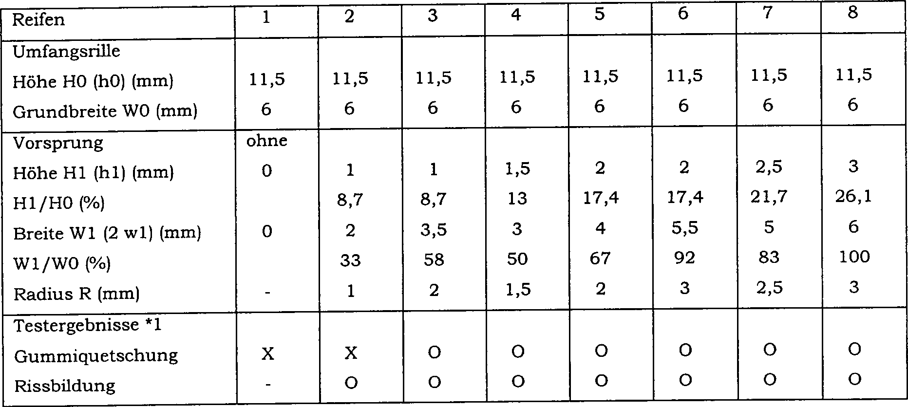
  • *1) O = nicht aufgetreten, X = aufgetreten Wie oben stehend erklärt, kann die vorliegende Erfindung geeigneterweise auf die oben erwähnten Geländediagonalreifen für Motorräder und Formen für diese angewendet werden, es ist jedoch auch möglich, sie auf verschiedene Reifen für Personenwagen und dergleichen und Formen für diese anzuwenden.* 1) O = not occurred, X = occurred As above explained, For example, the present invention may suitably ripen to the above-mentioned terrain diagonal for motorcycles and Shapes for However, it is also possible to apply them to different ones Mature for Passenger cars and the like and to apply forms for them.

Claims (10)

Luftreifen mit einem Laufflächenabschnitt (2), der mit Laufflächenrillen (G), die einen Rillengrund (9S) definieren, und einer Formtrennlinie (ML) in dem Rillengrund versehen ist, wobei die Formtrennlinie (ML) sich in Umfangsrichtung des Reifens erstreckt, dadurch gekennzeichnet, dass der Rillengrund mit einem Vorsprung (10) versehen ist, der radial nach außen von dem Rillengrund (9S) vorsteht und sich entlang der Formtrennlinie (ML) erstreckt, wobei der Vorsprung eine dreieckige Querschnittsform aufweist, die Breite (W) des Vorsprunges von dem Rillengrund (9S) bis zu dem radial äußeren Ende (10E) des Vorsprunges allmählich abnimmt und die Höhe des Vorsprunges das 0,1- bis 0,3-fache der Tiefe des Rillengrundes (9S) beträgt.Pneumatic tire having a tread portion ( 2 ) with tread grooves (G) having a groove bottom ( 9S ), and a mold parting line (ML) is provided in the groove bottom, wherein the mold parting line (ML) extends in the circumferential direction of the tire, characterized in that the groove bottom with a projection ( 10 ) which is radially outwardly from the groove bottom ( 9S ) and extends along the mold parting line (ML), the protrusion having a triangular cross-sectional shape, the width (W) of the protrusion from the groove bottom (ML) 9S ) to the radially outer end ( 10E ) of the projection gradually decreases and the height of the projection 0.1 to 0.3 times the depth of the groove bottom ( 9S ) is. Luftreifen nach Anspruch 1, dadurch gekennzeichnet, dass die Formtrennlinie (ML) sich innerhalb des Laufflächenmittelbereiches (Y) befindet, der eine axiale Breite von 20% der Laufflächenbreite zwischen den Laufflächenkanten aufweist.A pneumatic tire according to claim 1, characterized in that the mold parting line (ML) is within the tread center area (Y) having an axial width of 20% of the tread width between the tread edges having. Luftreifen nach Anspruch 1, dadurch gekennzeichnet, dass der Vorsprung (10) sich entlang des Reifenäquators erstreckt.A pneumatic tire according to claim 1, characterized in that the projection ( 10 ) extends along the tire equator. Luftreifen nach Anspruch 1, 2 oder 3, dadurch gekennzeichnet, dass der Vorsprung (10) eine Breite des 0,5- bis 1,0-fachen einer Rillenbreite am Rillengrund aufweist.A pneumatic tire according to claim 1, 2 or 3, characterized in that the projection ( 10 ) has a width of 0.5 to 1.0 times a groove width at the groove bottom. Luftreifen nach Anspruch 1, 2, 3 oder 4, dadurch gekennzeichnet, dass die Laufflächenrillen (G) den Laufflächenabschnitt (2S) in Laufflächenelemente unterteilen, und die Laufflächenelemente Laufflächenelemente umfassen, die sich auf der Formtrennlinie befinden und durch die der Vorsprung unterbrochen ist.A pneumatic tire according to claim 1, 2, 3 or 4, characterized in that the tread grooves (G) comprise the tread portion (11). 2S ) into tread elements, and the tread elements comprise tread elements located on the mold parting line and through which the projection is interrupted. Luftreifen nach Anspruch 1, 2, 3, 4 oder 5, gekennzeichnet durch eine Karkasse (6), die zwei gekreuzte Lagen aus Korden umfasst, die unter Schrägstellungswinkeln von 25 bis 60 Grad in Bezug auf die Umfangsrichtung des Reifens angeordnet sind.A pneumatic tire according to claim 1, 2, 3, 4 or 5, characterized by a carcass ( 6 ) comprising two crossed plies of cords arranged at skew angles of 25 to 60 degrees with respect to the circumferential direction of the tire. Form für einen Reifen, wobei der Reifen einen Laufflächenabschnitt (2) aufweist, der mit Laufflächenrillen (G) versehen ist, die einen Rillengrund (9S) definieren, und mit einer Laufflächen-Formungsfläche (22) zum Formen des Laufflächenabschnittes, und zumindest zwei Formen (21U, 21L), die geteilte Flächen (21) sind, welche eine Trennlinie (ML) auf der Laufflächen-Formungsfläche (22) bilden, wobei die Laufflächen-Formungsfläche (22) mit vorspringenden Teilen (25) zum Bilden der Laufflächenrillen (G) versehen ist, wobei die Trennlinie (ML) sich über zumindest einen der vorspringenden Teile erstreckt, so dass die Formtrennlinie (ML) in Umfangsrichtung in dem Rillengrund eines in der Form hergestellten Reifens verläuft, dadurch gekennzeichnet, dass in dem zumindest einen der vorspringenden Teile eine Ecke (K) zwischen der Laufflächen-Formungsfläche (22) und jeder der geteilten Flächen (21) durch einen konvexen Bogen abgeschnitten ist, so dass zwischen den geteilten Flächen ein allmählich abnehmender Spalt gebildet ist, und wobei die Höhe (h1) des Schnittes im Bereich des 0,1- bis 0,3-fachen der Höhe (h0) des vorspringenden Teils (25) liegt.Mold for a tire, the tire comprising a tread portion ( 2 ) provided with tread grooves (G) having a groove bottom ( 9S ) and with a tread molding surface ( 22 ) for forming the tread portion, and at least two shapes ( 21U . 21L ), the split areas ( 21 ) which have a parting line (ML) on the tread molding surface (FIG. 22 ), wherein the tread molding surface ( 22 ) with projecting parts ( 25 ) is provided for forming the tread grooves (G), wherein the parting line (ML) extends over at least one of the protruding parts so that the mold parting line (ML) extends circumferentially in the groove bottom of a molded tire, characterized in that in the at least one of the projecting parts a corner (K) between the tread molding surface ( 22 ) and each of the divided areas ( 21 ) is cut off by a convex arc so that a gradually decreasing gap is formed between the divided surfaces, and wherein the height (h1) of the cut is in the range of 0.1 to 0.3 times the height (h0) of the projecting Part ( 25 ) lies. Reifenform nach Anspruch 7, dadurch gekennzeichnet, dass die Trennlinie (ML) sich in einem Laufflächenmittelbereich erstreckt, der eine axiale Breite von 20% der Laufflächenbreite zwischen den Laufflächenkanten aufweist.Tire mold according to claim 7, characterized the parting line (ML) extends in a tread center region, an axial width of 20% of the tread width between the tread edges having. Reifenform nach Anspruch 7, dadurch gekennzeichnet, dass die Trennlinie (ML) sich entlang des Reifenäquators erstreckt.Tire mold according to claim 7, characterized the parting line (ML) extends along the tire equator. Verfahren zum Herstellen eines Reifens mit den Schritten, dass: eine Form bereitgestellt wird, die zumindest zwei Formen (21U, 21L) und eine Laufflächen-Formungsfläche (22) an den Formen zum Formen eines Laufflächenabschnittes des Reifens aufweist, wobei die zumindest zwei Formen (21U, 21L) geteilte Flächen (21) sind, die eine Trennlinie (ML) an der Laufflächen-Formungsfläche (22) bilden, wobei die Laufflächen-Formungsfläche (22) mit vorspringenden Teilen (25) zum Bilden von Laufflächenrillen (G) versehen wird, wobei die Trennlinie (ML) sich über zumindest einen der vorspringenden Teile erstreckt, so dass die Formtrennlinie (ML) in Umfangsrichtung in dem Rillengrund eines in der Form hergestellten Reifens verläuft, und wobei in zumindest einem der vorspringenden Teile eine Ecke (K) zwischen der Laufflächen-Formungsfläche (22) und jeder der geteilten Flächen (21) durch einen konvexen Bogen abgeschnitten wird, so dass zwischen den geteilten Flächen ein allmählich abnehmender Spalt gebildet wird, wobei die Höhe (h1) des Schnittes im Bereich des 0,1- bis 0,3-fachen der Höhe (h0) des vorspringenden Teils (25) liegt, ein Rohreifen in der Reifenform angeordnet wird, die Reifenform geschlossen und der Reifen vulkanisiert wird, die Reifenform geöffnet und der vulkanisierte Reifen entnommen wird.A method of manufacturing a tire comprising the steps of: providing a mold having at least two shapes ( 21U . 21L ) and a tread molding surface ( 22 ) on the molds for forming a tread portion of the tire, the at least two molds ( 21U . 21L ) divided areas ( 21 ) having a parting line (ML) at the tread molding surface (FIG. 22 ), wherein the tread molding surface ( 22 ) with projecting parts ( 25 ) is provided for forming tread grooves (G), wherein the parting line (ML) extends over at least one of the protruding parts, so that the mold parting line (ML) extends circumferentially in the groove bottom of a molded tire, and wherein at least one of the projecting parts a corner (K) between the tread molding surface ( 22 ) and each of the divided areas ( 21 ) is cut off by a convex arc so that a gradually decreasing gap is formed between the divided surfaces, the height (h1) of the cut being in the range of 0.1 to 0.3 times the height (h0) of the projecting part ( 25 ), placing a green tire in the tire mold, closing the tire mold and vulcanizing the tire, opening the tire mold and taking out the vulcanized tire.
DE2000620498 1999-12-09 2000-12-08 A pneumatic tire, and a vulcanizing mold, and a method of making such pneumatic tires Expired - Lifetime DE60020498T2 (en)

Applications Claiming Priority (2)

Application Number Priority Date Filing Date Title
JP35068699A JP3405701B2 (en) 1999-12-09 1999-12-09 Pneumatic tire and tire vulcanizing mold
JP35068699 1999-12-09

Publications (2)

Publication Number Publication Date
DE60020498D1 DE60020498D1 (en) 2005-07-07
DE60020498T2 true DE60020498T2 (en) 2006-04-27

Family

ID=18412163

Family Applications (1)

Application Number Title Priority Date Filing Date
DE2000620498 Expired - Lifetime DE60020498T2 (en) 1999-12-09 2000-12-08 A pneumatic tire, and a vulcanizing mold, and a method of making such pneumatic tires

Country Status (3)

Country Link
EP (1) EP1106392B1 (en)
JP (1) JP3405701B2 (en)
DE (1) DE60020498T2 (en)

Cited By (1)

* Cited by examiner, † Cited by third party
Publication number Priority date Publication date Assignee Title
FR3125461A1 (en) * 2021-07-26 2023-01-27 Compagnie Generale Des Etablissements Michelin HIGH SPEED LIMITED MOTORCYCLE TIRE

Families Citing this family (6)

* Cited by examiner, † Cited by third party
Publication number Priority date Publication date Assignee Title
JP4101549B2 (en) * 2002-04-15 2008-06-18 株式会社ブリヂストン Motorcycle tires
JP4542858B2 (en) 2004-04-15 2010-09-15 東洋ゴム工業株式会社 Heavy duty pneumatic tire
JP2006247921A (en) * 2005-03-09 2006-09-21 Yokohama Rubber Co Ltd:The Tire mold and pneumatic tire manufactured by tire mold
JP2006289737A (en) * 2005-04-08 2006-10-26 Bridgestone Corp Tire vulcanizing mold
JP7126964B2 (en) * 2019-02-18 2022-08-29 株式会社ブリヂストン motorcycle tires
IT202000003847A1 (en) * 2020-02-25 2021-08-25 Prometeon Tyre Group S R L MOLD FOR THE VOLCANIZATION OF VEHICLE TIRES

Family Cites Families (10)

* Cited by examiner, † Cited by third party
Publication number Priority date Publication date Assignee Title
DE3431655A1 (en) * 1984-08-29 1986-03-13 Continental Gummi-Werke Ag, 3000 Hannover VEHICLE TIRES
JPS63182109U (en) * 1987-05-19 1988-11-24
US5375639A (en) * 1991-07-10 1994-12-27 The Yokohhama Rubber Co., Ltd. Pneumatic tire
JP2955202B2 (en) * 1995-02-13 1999-10-04 住友ゴム工業株式会社 Pneumatic tire
JPH09323509A (en) * 1996-06-06 1997-12-16 Bridgestone Corp Pneumatic radial tire for passenger car or light truck running on rough road
IT1284979B1 (en) * 1996-10-18 1998-05-28 Pirelli Coodinamento Pneumatic TIRE WITH IMPROVED PERFORMANCE AND RELATED BIKE AND MANUFACTURING MOLD
JPH10151914A (en) * 1996-11-21 1998-06-09 Yokohama Rubber Co Ltd:The Pneumatic radial tire for heavy load
IT1289182B1 (en) * 1997-01-20 1998-09-29 Pirelli TIRE WITH LOW ROLLING RESISTANCE IN PARTICULAR FOR DRIVE WHEELS OF HEAVY VEHICLES
EP1124698B1 (en) * 1998-10-29 2002-12-18 PIRELLI PNEUMATICI S.p.A. Tyre and tread thereof
US6640858B2 (en) * 1999-12-07 2003-11-04 Sumitomo Rubber Industries, Ltd. Tire having tread grooves having right-hand groove wall and left-hand groove wall

Cited By (2)

* Cited by examiner, † Cited by third party
Publication number Priority date Publication date Assignee Title
FR3125461A1 (en) * 2021-07-26 2023-01-27 Compagnie Generale Des Etablissements Michelin HIGH SPEED LIMITED MOTORCYCLE TIRE
WO2023007071A1 (en) * 2021-07-26 2023-02-02 Compagnie Generale Des Etablissements Michelin Tyre for a motorcycle having a high top speed

Also Published As

Publication number Publication date
JP3405701B2 (en) 2003-05-12
EP1106392A3 (en) 2003-03-26
EP1106392B1 (en) 2005-06-01
JP2001163014A (en) 2001-06-19
DE60020498D1 (en) 2005-07-07
EP1106392A2 (en) 2001-06-13

Similar Documents

Publication Publication Date Title
DE602005001427T2 (en) Truck tires
DE1729752C2 (en) Method of making a radial tire
DE60117937T2 (en) A process for producing a rubber component for a pneumatic tire, pneumatic tire containing at least one such component, and a process for producing a pneumatic tire using at least one such component
DE112016000774T9 (en) tire
DE60033359T2 (en) tire
EP0548703B1 (en) Method and apparatus for making tyres
DE102008013769B4 (en) Method of making a pneumatic tire
DE102008012841B4 (en) Pneumatic tires and method of making such pneumatic tires
DE10360432A1 (en) Pneumatic tires and manufacturing process therefor
DE602005002692T2 (en) Method for producing a rubber element for tires
DE102007047134B4 (en) tire
DE102006002455B4 (en) tire
DE2944345A1 (en) RUBBER SPRING TIRES AND METHOD FOR THE PRODUCTION THEREOF
DE112018006716T5 (en) tire
DE60020498T2 (en) A pneumatic tire, and a vulcanizing mold, and a method of making such pneumatic tires
DE60304884T2 (en) SEGMENTED TIRE FOR REDUCING GRAT
EP1029715B1 (en) Vehicle tyre with a carcass, in particular radial, with sidewalls and with a tread
DE1937931A1 (en) Stretchable belt for use with belt tires
DE3102614A1 (en) RADIAL TIRE CARCASE AND METHOD FOR THEIR PRODUCTION
DE60117496T2 (en) Vulcanization mold for pneumatic tires
DE60305116T2 (en) Truck steering wheel, tire mold and molding process
DE1957213A1 (en) tire
DE102006009741B4 (en) tire
EP0591125B1 (en) Tyres
EP3475070B1 (en) Method for producing a solid rubber tyre and solid rubber tyre produced according to said method

Legal Events

Date Code Title Description
8364 No opposition during term of opposition