DE4124564B4 - Method and device for generating shaded images - Google Patents

Method and device for generating shaded images Download PDF

Info

Publication number
DE4124564B4
DE4124564B4 DE4124564A DE4124564A DE4124564B4 DE 4124564 B4 DE4124564 B4 DE 4124564B4 DE 4124564 A DE4124564 A DE 4124564A DE 4124564 A DE4124564 A DE 4124564A DE 4124564 B4 DE4124564 B4 DE 4124564B4
Authority
DE
Germany
Prior art keywords
change
reflection
vector
vertex
vertices
Prior art date
Legal status (The legal status is an assumption and is not a legal conclusion. Google has not performed a legal analysis and makes no representation as to the accuracy of the status listed.)
Expired - Fee Related
Application number
DE4124564A
Other languages
German (de)
Other versions
DE4124564A1 (en
Inventor
Stuart Sunnyvale Wells
James Los Altos Van Loo
Jack R. Cupertino McKeown
Mukund San Jose Bhakta
Current Assignee (The listed assignees may be inaccurate. Google has not performed a legal analysis and makes no representation or warranty as to the accuracy of the list.)
Sun Microsystems Inc
Original Assignee
Sun Microsystems Inc
Priority date (The priority date is an assumption and is not a legal conclusion. Google has not performed a legal analysis and makes no representation as to the accuracy of the date listed.)
Filing date
Publication date
Application filed by Sun Microsystems Inc filed Critical Sun Microsystems Inc
Publication of DE4124564A1 publication Critical patent/DE4124564A1/en
Application granted granted Critical
Publication of DE4124564B4 publication Critical patent/DE4124564B4/en
Anticipated expiration legal-status Critical
Expired - Fee Related legal-status Critical Current

Links

Classifications

    • GPHYSICS
    • G06COMPUTING; CALCULATING OR COUNTING
    • G06TIMAGE DATA PROCESSING OR GENERATION, IN GENERAL
    • G06T1/00General purpose image data processing
    • GPHYSICS
    • G06COMPUTING; CALCULATING OR COUNTING
    • G06TIMAGE DATA PROCESSING OR GENERATION, IN GENERAL
    • G06T15/003D [Three Dimensional] image rendering
    • G06T15/50Lighting effects
    • G06T15/80Shading
    • G06T15/83Phong shading

Landscapes

  • Engineering & Computer Science (AREA)
  • Physics & Mathematics (AREA)
  • General Physics & Mathematics (AREA)
  • Theoretical Computer Science (AREA)
  • Computer Graphics (AREA)
  • Image Generation (AREA)
  • Image Analysis (AREA)

Abstract

Einrichtung zum Erzeugen von bezüglich einer Lichtquelle schattierten Abbildungen eines auf einer graphischen Anzeigeeinrichtung anzuzeigenden graphischen Bildes, wobei die graphische Anzeigeeinrichtung eine Matrix von Pixeln aufweist,
wobei die erzeugte schattierte Abbildung von einer von einem Benutzer spezifizierten Qualität ist,
wobei die Einrichtung eine zentrale Verarbeitungseinheit (CPU), einen Speicher und einen mit der graphischen Anzeigeeinrichtung verbundenen Einzelbildpuffer aufweist,
wobei die schattierte Abbildung durch eine Vielzahl von Pixeldaten definiert ist,
wobei die Pixeldaten in dem Einzelbildpuffer gespeichert sind,
wobei die Pixeldaten einen Pixelort auf der graphischen Anzeigeeinrichtung und eine Pixelfarbe spezifizieren,
wobei die schattierte Abbildung auf der graphischen Anzeigeeinrichtung entsprechend den in dem Einzelbildpuffer gespeicherten Pixeldaten angezeigt wird,
wobei die Einrichtung ferner aufweist:
a) mit der CPU und dem Einzelbildpuffer gekoppelte Schattierungsmittel, die aufweisen:
1) mit der CPU gekoppelte Eingabemittel zum Empfangen einer Vielzahl von Polygonen von der CPU, welche das graphische Bild...
Apparatus for generating shaded images of a light image to be displayed on a graphical display device, the graphical display having a matrix of pixels,
wherein the generated shaded image is of a quality specified by a user,
the device comprising a central processing unit (CPU), a memory and a frame buffer connected to the graphical display device,
wherein the shaded image is defined by a plurality of pixel data,
wherein the pixel data is stored in the frame buffer,
wherein the pixel data specifies a pixel location on the graphical display device and a pixel color,
wherein the shaded image is displayed on the graphical display device according to the pixel data stored in the frame buffer,
the device further comprising:
a) shading means coupled to the CPU and the frame buffer comprising:
1) input means coupled to the CPU for receiving a plurality of polygons from the CPU which displays the graphic image ...

Figure 00000001
Figure 00000001

Description

Die Erfindung bezieht sich auf ein Verfahren und eine Einrichtung zur Erzeugung von Bildern durch Computer. Insbesondere bezieht sich die Erfindung auf das Schattieren von Computerbildern.The The invention relates to a method and a device for Generation of images by computer. In particular, refers the invention to the shading of computer images.

In einem Computergraphiksystem, welches digitale Bilder erzeugt, wird die Oberfläche eines Objekts typischerweise durch ein Netzwerk von ebenen Polygonen dargestellt. Diese Polygone können durch Benutzung bekannter Techniken schnell transformiert und wiedergegeben werden. Bei diesen Techniken wird angenommen, daß die Eingangsgröße ein einfaches Dreieck ist, bei dem die Attribute der Eckpunkte die Position, die Normale und die Farbe sind. Die Lage des Eckpunkts ist beispielsweise im Objektkoordinatenraum definiert. Die Eckpunktnormalen sind Einheitsvektoren, welche die Oberflächenorientierung an jedem Eckpunkt beschreiben. Die Eckpunktfarbe spezifiziert die eigene Farbe des Objekts. Die Eckpunktfarbe gestattet es, die Farbe des Objekts über das Dreieck zu variieren.In a computer graphics system which generates digital images the surface of an object typically through a network of planar polygons shown. These polygons can quickly transformed and reproduced using known techniques become. These techniques assume that the input is a simple one Triangle is where the attributes of the vertices are the position, the Normal and the color are. The location of the vertex is, for example defined in object coordinate space. The vertex normals are unit vectors, which the surface orientation describe at each vertex. The vertex color specifies the own color of the object. The vertex color allows the color of the object over to vary the triangle.

Um ein realistisches Bild eines Objekts auf einem Computergraphikdisplay zu erzeugen, muß nicht nur der Umriß des Objekts erzeugt werden, sondern es muß auch die Schattierung der sichtbaren Oberflächen des Objekts eingeschlossen werden, wobei die Lichtquellen, Oberflächencharakteristiken und die Anordnungen und Orientierungen der Oberflächen und Quellen zu berücksichtigen sind. Eine Kombination von drei Reflexionsfunktionen kann benutzt werden, um die Schattierung eines Bildes zu bestimmen. Diese drei Reflexionsfunktionen sind die ambiente, die diffuse und die spiegelnde Reflexion. Die ambiente Reflexion ist das Licht von willkürlich angeordneten Lichtquellen, welches das Objekt absorbiert und dann ausstrahlt. Hierbei gibt es keine Abhängigkeit von der Richtung des Lichts. Die ambiente Funktion wichtet einfach die Farbe des Objekts. Beispielsweise kann mit den ambienten Gewichten für rot, grün und blau, Kar, Kag, Kab, die Funktion der ambienten Reflexion wie folgt beschrieben werden: Iar = Kar·Cr Iag = Kag·Cg Iab = Kab·Cb,wobei Iar, Iag, Iab die ambienten Reflexionen für den roten, grünen und blauen Farbbestandteil, Kar, Kag, Kab die ambienten Gewichte für die Farbbestandteile Rot, Grün und Blau und Cr, Cg, Cb die Objektfarben oder Farbintensitäten für die roten, grünen und blauen Bestandteile des Objekts sind. Der Wertebereich der ambienten Gewichte ist: 0 ≤ Kar ≤ 1, 0 ≤ Kag ≤ 1, 0 ≤ Kab ≤ 1 In order to produce a realistic image of an object on a computer graphics display, not only must the outline of the object be created, but also the shading of the object's visible surfaces must be included, including the light sources, surface characteristics, and the arrangements and orientations of the surfaces and sources to take into account. A combination of three reflection functions can be used to determine the shading of an image. These three reflection functions are ambiente, diffuse and specular reflection. The ambiente Reflection is the light of arbitrarily arranged light sources, which absorbs the object and then radiates. There is no dependence on the direction of the light. The ambiente function simply weights the color of the object. For example, with the ambient weights for red, green and blue, Ka r , Ka g , Ka b , the function of the ambient reflection can be described as follows: Ia r = Ka r · C r Ia G = Ka G · C G Ia b = Ka b · C b . where Ia r , Ia g , Ia b the ambient reflections for the red, green and blue color component, Ka r , Ka g , Ka b the ambient weights for the color components red, green and blue and C r , C g , C b the Object colors or color intensities are for the red, green and blue components of the object. The value range of the ambient weights is: 0 ≤ Ka r ≤ 1, 0 ≤ Ka G ≤ 1, 0 ≤ Ka b ≤ 1

Es sollte angemerkt werden, daß die ambienten Gewichte Kar, Kag, Kab und die unten genannten Gewichte der diffusen Reflexion Kdr, Kdg, Kdb in Wirklichkeit ein Produkt aus zwei Termen sind. Der erste Term drückt die Lichtintensität der Komponente aus. Der zweite Term drückt die Fähigkeit der Objektoberfläche aus, diese Komponente zu reflektieren. Da keiner der Terme von der Geometrie der Szene abhängt, werden in den vorliegenden Betrachtungen die zwei Terme in den Gewichten kombiniert. Enthält die Szene mehrfache Lichtquellen, so gibt es separate Gewichte für jede Lichtquelle.It should be noted that the ambient weights Ka r , Ka g , Ka b and the below-mentioned weights of the diffuse reflection Kd r , Kd g , Kd b are actually a product of two terms. The first term expresses the light intensity of the component. The second term expresses the ability of the object surface to reflect that component. Since none of the terms depends on the geometry of the scene, in the present considerations the two terms in the weights are combined. If the scene contains multiple light sources, there are separate weights for each light source.

Stumpfe, matte Oberflächen zeigen diffuse Reflexionen, die das Licht gleichmäßig in alle Richtungen streuen, so daß die Oberfläche aus allen Blickwinkeln die gleiche Helligkeit zu haben scheint. Bei solchen Oberflächen setzt das Lambert'sche Kosinus-Gesetz die Menge des reflektierten Lichtes zum Kosinus des Winkels α zwicgen der Richtung L zur Punktlichtquelle und dem Normalenvektor N der Oberfläche, wie sie in 1a dargestellt sind, in Beziehung. Die diffuse Reflexion kann durch die folgende Gleichung ausgedrückt werden: Idr = cos(α)·Kdr·Cr Idg = cos(α)·Kdg·Cg Idb = cos(α)·Kdb·Cb,wobei cos(α) = N·L ist (da die diffuse Reflexion einen positiven Wert haben muß, ist für die Berechnung von cos(α) zu for dern: cos(α) = max(cos(α), 0).), Idr, Idg bzw. Idb die diffusen Reflexionswerte für die roten, grünen und blauen Elemente, Kdr, Kdg und Kdb die diffusen Reflexionskoeffizienten für die roten, grünen und blauen Elemente der Lichtquelle (welche eine Konstante zwischen 0 und 1 sind und in Abhängigkeit vom Material der Oberfläche variieren) und Cr, Cg, und Cb die Farben der roten, grünen und blauen Elemente der Oberfläche sind.Dull, dull surfaces show diffuse reflections, which scatter the light evenly in all directions, so that the surface appears to have the same brightness from all angles. In such surfaces, Lambert's law of cosines sets the amount of reflected light to the cosine of the angle α between the direction L to the point light source and the normal vector N of the surface as shown in FIG 1a are shown in relationship. The diffuse reflection can be expressed by the following equation: id r = cos (α) · Kd r · C r id G = cos (α) · Kd G · C G id b = cos (α) · Kd b · C b . where cos (α) = N · L (since the diffuse reflection must have a positive value, for the calculation of cos (α) one has to: cos (α) = max (cos (α), 0).) , Id r , Id g and Id b the diffuse reflectance values for the red, green and blue elements, Kdr, Kdg and Kdb, the diffuse reflection coefficients for the red, green and blue elements of the light source (which are a constant between 0 and 1 and vary depending on the material of the surface) and C r , C g , and C b the colors of the surface are red, green and blue elements.

Die spiegelnde Reflexion ist das auf einer glänzenden Oberfläche zu beobachtende Glanzlicht. Das von Bui Tuong-Phong entwickelte Modell modelliert die spiegelnde Reflexion als eine Funktion vom Kosinus des Winkels zwischen V, dem Vektor zum Punkt des Beobachters, und R, dem Vektor, der in Richtung der maximalen Reflexion zeigt, wie es in 1b dargestellt ist (Phong, B.T. "Illumination for Computer Generated Images", PhD Dissertation, Dept. of Computer Science, University of Utah, Salt Lake City, Gov. Ordering No. AD-A0008-786 (Juli 1973)). Für weitere Informationen über die ambiente, die diffuse und die spiegelnde Reflexion siehe auch: Foley und Van Dam "Fundamentals of Interactive Computer Graphics", (Addison Wesley 1983), Seiten 575–580; und Cook und Torrance, "A Reflectance Model For Computer Graphics", Computer Graphics, Bd. 15, Nr. 3, August 1981.Reflective reflection is the highlight on a glossy surface. The model developed by Bui Tuong-Phong models the specular reflection as a function of the cosine of the angle between V, the vector to the point of the observer, and R, the vector pointing in the direction of maximum reflection, as in 1b (Phong, BT "Illumination for Computer Generated Images", PhD Dissertation, Dept. of Computer Science, University of Utah, Salt Lake City, Gov. Ordering No. AD-A0008-786 (July 1973)). For more information on ambient, diffuse, and specular reflection, see: Foley and Van Dam "Fundamentals of Interactive Computer Graphics," (Addison Wesley 1983), pp. 575-580; and Cook and Torrance, "A Reflectance Model For Computer Graphics", Computer Graphics, Vol. 15, No. 3, August 1981.

Die reflektierte Lichtmenge ist additiv. Folglich wird, wenn drei separate Lichtquellen auf eine Oberfläche scheinen, die auf der Oberfläche reflektierte Lichtmenge dadurch berechnet, daß die Reflexionsstärke in bezug auf jede Lichtquelle bestimmt und die für alle Lichtquellen bestimmten Reflexionsanteile summiert werden. Bei der Bestimmung der Art und der Menge der Reflexion sollte man sich vergegenwärtigen, daß es drei verschiedene Arten von Lichtquellen gibt. Ein Fall tritt auf, wenn in der Lösung angenommen wird, daß die Entfernung zum Licht unendlich ist. Die Beschreibung der Lichtquelle reduziert sich zu dem folgenden einfachen Lichtvektor: L = (Lx, Ly, Lz), wobei sich der Betrag des Lichtvektors zu

Figure 00040001
ergibt und der Wert von |L| gleich 1 für eine Lichtquelle im Unendlichen ist.The reflected amount of light is additive. Consequently, when three separate light sources shine on one surface, the amount of light reflected on the surface is calculated by determining the reflectivity with respect to each light source and summing the reflection ratios determined for all the light sources. In determining the type and amount of reflection, it should be remembered that there are three different types of light sources. A case occurs when the solution assumes that the distance to the light is infinite. The description of the light source reduces to the following simple light vector: L = (Lx, Ly, Lz), wherein the amount of the light vector increases
Figure 00040001
results and the value of | L | is equal to 1 for a light source at infinity.

Ein anderer Fall tritt auf, wenn die Lösung annimmt, daß die Entfernung zur Lichtquelle endlich, aber die Strahlungscharakteristik isotrop ist. Das Licht strahlt folglich in alle Richtungen mit der gleichen Intensität. Die Beschreibung der Lichtquelle reduziert sich in diesem Fall auf die Position des Lichtes: Q = (Qx, Qx, Qz). Another case occurs when the solution assumes that the distance to the light source is finite, but the radiation characteristic is isotropic. The light therefore radiates in all directions with the same intensity. The description of the light source in this case is reduced to the position of the light: Q = (Qx, Qx, Qz).

Der Lichtvektor, also die Position des Lichtes relativ zur Position des Eckpunktes (Px, Py, Pz) ist: L = (Qx – Px, Qy – Py, Qz – Pz)mit dem Betrag:

Figure 00040002
The light vector, ie the position of the light relative to the position of the vertex (Px, Py, Pz) is: L = (Qx-Px, Qy-Py, Qz-Pz) with the amount:
Figure 00040002

Da der Betrag nicht gleich 1 sein kann, aber die Beleuchtungsstärkegleichungen einen Einheitsvektor erfordern, wird der Lichtvektor normiert: L = ((Qx – Px)/|L|, (Qy – Py)/|L|, (Qz – Pz)/|L|). Since the amount can not equal 1, but the illuminance equations require a unit vector, the light vector is normalized: L = ((Qx - Px) / | L |, (Qy - Py) / | L |, (Qz - Pz) / | L |).

Ein dritter Fall tritt auf, wenn die Strahlungscharakteristik nicht isotrop ist. Wenn die Strahlungscharakteristik nicht isotrop ist, erfordert die Beschreibung der Lichtquelle den Vektor des Strahlungsdiagramms, welcher die Strahlungscharakteristikfunktion beschreibt: K = (Kx, Ky, Kz). A third case occurs when the radiation characteristic is not isotropic. If the radiation characteristic is not isotropic, the description of the light source requires the vector of the radiation pattern describing the radiation characteristic function: K = (Kx, Ky, Kz).

Der Strahlungscharakteristik-Vektor dient zur Beschreibung der Richtung, in welcher die Lichtintensität ein Maximum hat. Das das Objekt überstreichende Licht nimmt dann ab, wenn der Winkel κ zwischen dem Lichtvektor L und dem Strahlungscharakteristik-Vektor κ zunimmt (siehe 2). Vor dem Einbeziehen der Strahlungscharakteristikfunktion ist der Lichtvektor wie zuvor: L = ((Qx – Px)/|L|, (Qy – Py)/|L|, (Qz – Pz)/|L|)mit dem Betrag:

Figure 00050001
The radiation characteristic vector is used to describe the direction in which the light intensity has a maximum. The light passing over the object then decreases as the angle κ between the light vector L and the radiation characteristic vector κ increases (see FIG 2 ). Before incorporating the radiation characteristic function, the light vector is as before: L = ((Qx-Px) / | L |, (Qy-Py) / | L |, (Qz-Pz) / | L |) with the amount:
Figure 00050001

Die Strahlungscharakteristikfunktion, welche die Intensität als Funktion vom Winkel zwischen dem Lichtvektor und dem Strahlungscharakteristik-Vektor darstellt, ist oftmals: cos(κ) = Kx·Lx + Ky·Ly + Kz·Lz. The radiation characteristic function, which represents the intensity as a function of the angle between the light vector and the radiation characteristic vector, is often: cos (κ) = Kx * Lx + Ky * Ly + Kz * Lz.

Unter Aufnahme dieses Werts wird der Lichtvektor zu: L = (cos(κ)·Lx, cos(κ)Ly, cos(κ)Lz). Taking this value, the light vector becomes: L = (cos (κ) * Lx, cos (κ) Ly, cos (κ) Lz).

Computergraphiksysteme stellen gewöhnlich gekrümmte Oberflächen von Bildern als ein Netzwerk von ebenen Polygonen dar, welche schattiert sind, um ein weiches Erscheinungsbild wiederzugeben. Die Systeme versuchen das weiche Erscheinungsbild durch Variieren der Intensität über die Polygone wiederzugeben. Bekannte Techniken zum realistischen Schattieren von Polygonen werden aufgrund ihres großen Rechenaufwands von Echtzeitsystemen nicht benutzt. Die am einfachsten auszuführende Schattierungsberechnung ist die Berechnung der diffusen Reflexion, welche dem Lambert'schen Gesetz für diffuses Licht folgt. Jedoch nimmt diese Berechnung die gleiche Reflexionshelligkeit aus allen Blickwinkeln an. Da die einfache diffuse Gleichung die Reflexionsgleichungen nicht unter Beachtung der physikalischen Eigenschaften der Oberfläche, beispielsweise einem Rauheits-Koeffizienten, ausrechnet, nähert der Ausdruck die Reflexion nur an. Der Ausdruck kann beispielsweise nicht beschreiben, wie sich die Wellenlänge in Abhängigkeit vom Einfallswinkel verschieben kann, wenn das Licht eine metallische Oberfläche überstreicht. Diese Wellenlängenverschiebung bewirkt eine Veränderung der Farbe. Auch berücksichtigt die einfache diffuse Gleichung nicht, wie das Licht von Oberfläche zu Oberfläche gestreut wird.Computer graphics systems usually make curved surfaces of images as a network of planar polygons shading are to give a soft appearance. The systems try the soft appearance by varying the intensity over the Play polygons. Well-known techniques for realistic shading of polygons are due to their large computational effort of real-time systems not used. The easiest shading calculation to perform is the calculation of the diffuse reflection, which according to Lambert's law for diffuse reflection Light follows. However, this calculation takes the same reflection brightness from all angles. Because the simple diffuse equation is the Reflection equations not considering the physical properties the surface, for example a roughness coefficient, the expression approximates the reflection only at. For example, the expression can not describe how the wavelength dependent on from the angle of incidence can shift when the light is a metallic Surface sweeps over. This wavelength shift causes a change the color. Also considered The simple diffuse equation does not like the light scattered from surface to surface becomes.

Außerdem nimmt die einfachste Version der diffusen Reflexion an, daß die Reflexion über die gesamte Seitenfläche oder das gesamte Polygon konstant ist. Obwohl dies einfach zu berechnen ist, ist die Intensität oftmals an den Grenzen zwischen den Polygonen diskontinuierlich. Eine verbesserte Technik zur Ausführung des Schattierens von Bildern in Echtzeit wird als Gouraud-Schattieren bezeichnet. Bei der Gouraud-Schattierungstechnik wird die Intensität an jedem Punkt durch lineare Interpolation der Intensitäten an den Eck- oder Scheitelpunkten der Polygone berechnet. Diese Intensitäten werden durch Nutzung der Reflexionsgleichung für die diffuse Reflexion mit den an den Eckpunkten gegebenen Normalen bestimmt. Weitere Informationen über die Gouraud-Schattierung siehe: Gouraud, H. "Continuous Shading of Curved Surfaces", IEEE Transactions on Computers, Bd. 20, Nr. 6, Seiten 623–628 (Juni 1971). Jedoch läßt sich diese Technik nur für diffuse Reflexionen anwenden, und somit erscheinen durch diese Technik schattierte Oberflächen matt. Außerdem können die Bilder infolge von diskontinuierlichen Intensitätsänderungen an den Polygongrenzen Mach-Bänder reflektieren.It also takes the simplest version of diffuse reflection indicates that the reflection on the entire side surface or the entire polygon is constant. Although this is easy to calculate is, the intensity is often at the boundaries between the polygons discontinuously. An improved Technique for the execution of the Shading images in real time is called Gouraud Shading designated. In the Gouraud shading technique, the intensity at each Point by linear interpolation of the intensities at the corner or vertices the polygons are calculated. These intensities are created by using the Reflection equation for the diffuse reflection with the normals given at the vertices certainly. More information about Gouraud shading see: Gouraud, H. Continuous Shading of Curved Surfaces, IEEE Transactions on Computers, Vol. 20, No. 6, pages 623-628 (June 1971). However, it is possible this technique only for apply diffuse reflections, and thus appear through this technique shaded surfaces frosted. In addition, the Images due to discontinuous intensity changes at the polygon boundaries Reflect Mach bands.

Die Phong-Schattierungstechnik erleuchtet die matten Oberflächen und reduziert die Mach-Bänder, welche die Gouraud-Schattierungstechnik erzeugt, aber sie wird aufgrund der langen Rechenzeit und des für die Erzeugung des Bildes erforderlichen Aufwandes gewöhnlich nicht in Echtzeitsystemen benutzt. In dieser Technik wird die Intensität jedes Punktes durch Verwendung einer angenäherten Oberflächennormalen bestimmt, welche aus den an den Eckpunkten beschriebenen tatsächlichen Oberflächennormalen linear interpoliert wird. Das Phong-Schattieren nutzt die Gleichung N(x,y) = Ax + By + C, wobei A, B und C die ausgewählten Eckpunkte sind, um die Normale über das Polygon zu interpolieren. Die Phong-Schattierungsgleichung erfordert sieben Additionen, sechs Multiplikationen, eine Division und eine Quadratwurzel pro Pixel. Diese Operation ist sehr aufwendig und zeitintensiv, insbesondere weil sie die Berechnung der Quadratwurzel einschließt. Zu weiteren Informationen über das Phong-Schattieren siehe: Phong B.T. "Illumination for Computer Generated Images", PhD Dissertation, Dept. of Computer Science, University of Utah, Salt Lake City, Gov. Ordering No. AD-A0008- 786.The Phong shading technology enlightens the matte surfaces and reduces the Mach bands, which the Gouraud shading technique but it is due to the long computation time and the generation time the image required effort usually not in real-time systems used. In this technique, the intensity of each point is determined by use an approximate surface normal determines which of the actual ones described at the vertices surface normal is linearly interpolated. Phong shading uses the equation N (x, y) = Ax + By + C, where A, B and C are the selected vertices are about the normals over to interpolate the polygon. The Phong shading equation requires seven additions, six multiplications, one division and one Square root per pixel. This operation is very elaborate and time consuming, especially because they are calculating the square root includes. To more information about the phong shading see: Phong B.T. "Illumination for Computer Generated Images ", PhD Dissertation, Dept. of Computer Science, University of Utah, Salt Lake City, Gov. Ordering No. AD-A0008-786.

Die Berechnung der Phong-Schattierung wurde durch Tom Duff vereinfacht (beschrieben in "Smoothly Shaded Renderings of Polyhedral Objects on Raster Displays", ACM Computer Graphics, Bd. 13, Nr. 2, Seiten 270–275, 1979). Duff vereinfachte das Phong-Schattieren durch Kombination der Interpolation der Reflexionsgleichungen:

Figure 00070001
The computation of phong shading was simplified by Tom Duff (described in "Smoothly Shaded Renderings of Polyhedral Objects on Raster Displays", ACM Computer Graphics, Vol. 13, No. 2, pp. 270-275, 1979). Duff simplified phong shading by combining the interpolation of the reflection equations:
Figure 00070001

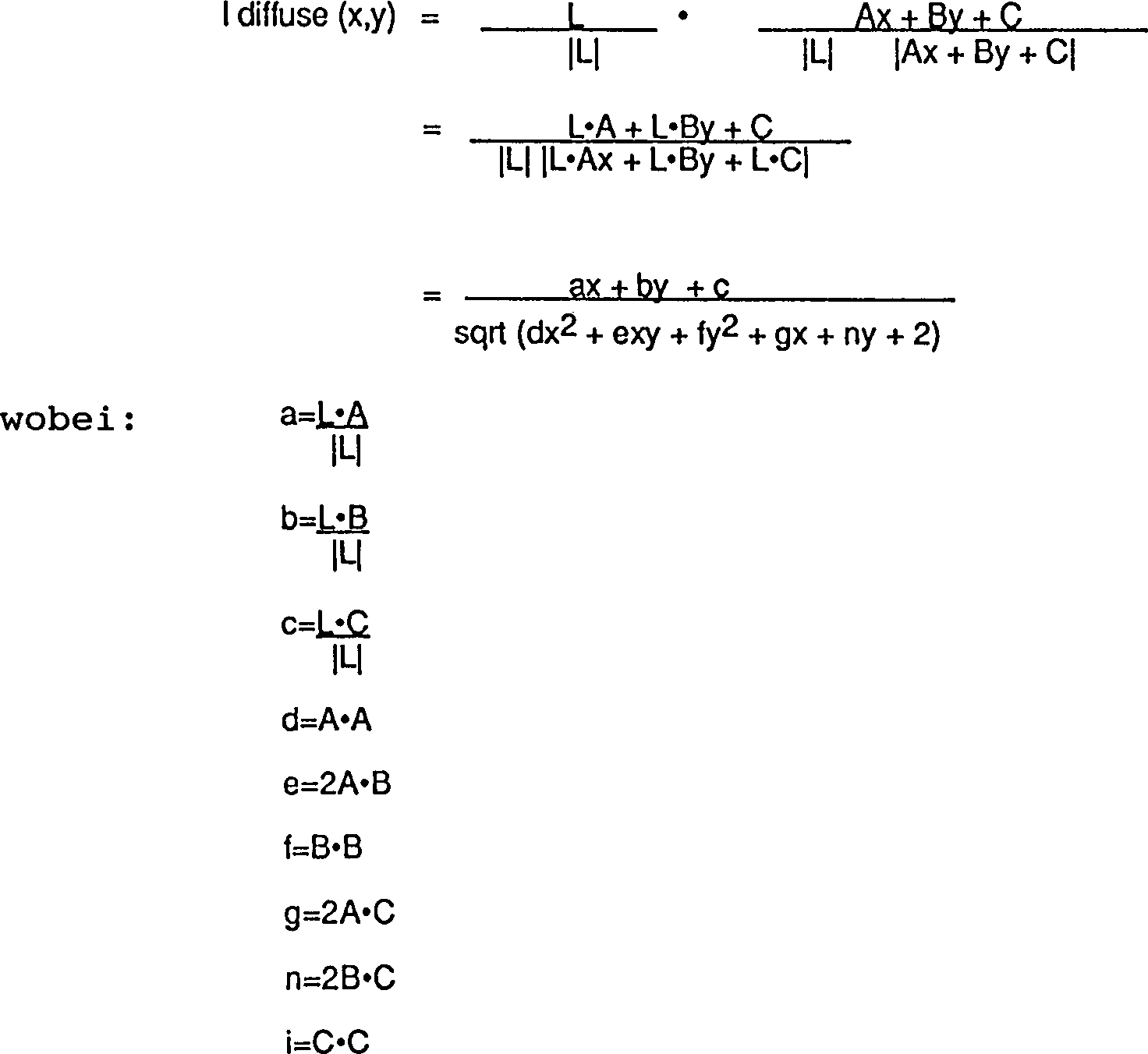
Somit kann diese Implementierung für aufeinanderfolgende Werte von x und y ausgewertet werden mit nur drei Additionen, einer Division und einer Quadratwurzel pro Pixel. Obwohl dies eine Verbesserung gegenüber Phong's Formel ist, machen die Berechnungen der Division und Quadratwurzel die Technik noch zu zeitintensiv und aufwendig für Echtzeitrealisierungen.Consequently can this implementation for successive values of x and y are evaluated using only three additions, one division and one square root per pixel. Although this is an improvement over Phong's formula, do the calculations the division and square root the technology still too time-consuming and elaborate for Real-time implementations.

In einer anderen Implementierung des Phong-Schattierens wird eine Näherung der Reflexionsgleichung berechnet, wobei Zeit und Aufwand gegenüber der exakten Berechnung der Reflexionsgleichung gespart werden. In Weimer "Fast Phong Shading", Computer Graphics, Bd. 20, Nr. 4, (1986), Seiten 103–105 wird eine Taylor-Reihen-Näherung zweiter Ordnung benutzt, um die Reflexion zu berechnen. Um die Näherung zu vereinfachen, wird das Polygon so verschoben, daß der Koordinatennullpunkt im Zentrum des Polygons liegt. Mit Hilfe dieser Technik kann die Intensität an einem Pixel durch nur zwei Additionen pro Pixel bewertet werden.In another implementation of phong shading will approximate the Computed reflection equation, taking time and effort against the exact calculation of the reflection equation can be saved. In Weimer's "Fast Phong Shading", Computer Graphics, Vol. 20, No. 4, (1986), pages 103-105, a Taylor series approximation becomes second Order used to calculate the reflection. To the approximation too simplify, the polygon is shifted so that the coordinate zero point lies in the center of the polygon. With the help of this technique, the intensity be evaluated on a pixel by only two additions per pixel.

Jedoch werden in allen o.g. Techniken die gleichen Funktionen benutzt, um die Reflexion aller Polygone eines Bildes zu bestimmen. Aus Bergman, L. et al. "Image Rendering by Adaptive Refinement", Computer Graphics, Vol 20. No. 4, August 1986 ist ein Verfahrung zur Schattierung bekannt, bei dem an einigen der Polygone in Abfolge wiederholt zunehmend komplexe Schattierungsverfahren ausgeführt werden. Zunächst werden bei dem bekannten Verfahren alle Polygone mit einem Schattierungsverfahren geringen Komplexität schattiert.however be in all o.g. Techniques using the same functions to determine the reflection of all polygons of an image. From Bergman, L. et al. "Image Rendering by Adaptive Refinement ", Computer Graphics, Vol. 4, August 1986 is a procedure known for shading, in which at some of the polygons in sequence increasingly complex shading procedures are performed. First, be in the known method all polygons with a shading method low complexity shaded.

Die DE 38 25 539 A1 offenbart ein Verfahren und eine Einrichtung zum Schattieren von Bildern durch Wiedergabe einer Serie benachbarter Pixelkurven derart, daß keine Lücken zwischen den wiedergegebenen Kurven entstehen.The DE 38 25 539 A1 discloses a method and apparatus for shading images by rendering a series of adjacent pixel curves such that no gaps arise between the rendered curves.

Wenn die Reflexion für einige der Polygone des Bildes nur dann mit der gewünschten Qualität bestimmt werden kann, wenn ein komplexer zeitintensiver Prozeß benutzt wird, so werden alle Polygone unter Verwendung desselben Prozesses bearbeitet. Somit wird, um ein Qualitätsbild wiederzugeben, ein komplexer zeitintensiver Prozeß benutzt, obwohl die Reflexion für eine bedeutende Anzahl von Polygonen durch einen einfacheren, schnelleren Prozeß bestimmt werden könnte.If the reflection for some of the polygons of the image only with the desired one quality can be determined when using a complex time consuming process so all polygons will be using the same process processed. Thus, to render a quality picture, it becomes more complex in time Process used, although the reflection for a significant number of polygons through a simpler, faster one Process determined could be.

Aufgabe der vorliegenden Erfindung ist es, eine Einrichtung und ein Verfahren zur Erzeugung von schattierten Abbildungen zu schaffen, die bzw. das den Aufwand an Rechnerressourcen und Zeit derart reduziert, daß schattierte Bilder in Echtzeit zur Verfügung gestellt werden können.task It is the object of the present invention to provide a device and a method to create shaded images which that reduces the amount of computational resources and time, that shaded Images in real time available can be made.

Die Aufgabe wird erfindungsgemäß gelöst durch eine Einrichtung mit den Merkmalen des Patentanspruchs 1 und ein Verfahren mit den Merkmalen des Patentanspruchs 52.The The object is achieved by a device having the features of claim 1 and a Method with the features of claim 52.

Die Erfindung verwendet ein adaptives Schattierungsverfahren, um schattierte Bilder in Echtzeit zu erzeugen. Zuerst wird die Farbe oder die Intensität an jeder der Ecken des Polygons berechnet. Dann wird eine Folge von Tests ausgeführt, um die Ordnung der Gleichung zu bestimmen, welche benutzt werden soll, um die Farbe oder die Intensität über das Polygon zwischen den Eckpunkten zu interpolieren. Gemäß dieser Technik wird bei Po lygonen, die eine leichte oder keine Krümmung haben, und bei einer unendlich entfernten Lichtquelle (dies ist die einfachste Form des Schattierens) eine extrem schnelle Gleichung niederer Ordnung benutzt, um über das Polygon zu interpolieren. Bei Polygonen, die einen hohen Grad der Krümmung und/oder der Positionsveränderung der Lichtquelle aufweisen, wird ggf. eine Gleichung höherer Ordnung benutzt, welche zusätzliche Rechenzeit erfordert, aber wünschenswerte Schattierungsergebnisse erzeugt.The Invention uses an adaptive shading method to shade Create images in real time. First, the color or the intensity at each calculated from the corners of the polygon. Then a series of tests executed to determine the order of the equation that will be used should be to change the color or intensity across the polygon between the Interpolate vertices. According to this Technique is used in polygons that have a slight or no curvature, and at an infinitely distant light source (this is the simplest Form of shading) an extremely fast low-order equation used to over to interpolate the polygon. For polygons that have a high degree the curvature and / or the position change the light source, if necessary, a higher order equation used which additional Compute time required, but desirable Shading results generated.

Im folgenden wird die Erfindung anhand von in der Zeichnung dargestellten Ausführungsbeispielen näher erläutert. In der Zeichnung zeigen:in the Following is the invention with reference to shown in the drawing embodiments explained in more detail. In show the drawing:

1a die in der Berechnung der diffusen Reflexion benutzte Geometrie; 1a the geometry used in the calculation of the diffuse reflection;

1b die in der Berechnung der spiegelnden Reflexion benutzte Geometrie; 1b the geometry used in the calculation of the specular reflection;

2 die Geometrie, die bei Lichtquellen mit anisotroper Strahlungscharakteristik benutzt wird; 2 the geometry used in light sources with anisotropic radiation characteristics;

3 ein im System der vorliegenden Erfindung benutztes Computersystem; 3 a computer system used in the system of the present invention;

4a, 4b und 4c die Ausleuchtung der Oberflächen, welche zur Erzeugung qualitativ guter schattierter Bilder Gleichungen höherer Ordnung erfordert; 4a . 4b and 4c the illumination of the surfaces, which requires higher order equations to produce good quality shaded images;

5 ein Ablaufdiagramm, welches ein bevorzugtes Ausführungsbeispiel der Erfindung darstellt; 5 a flow chart illustrating a preferred embodiment of the invention;

6a und 6b Ablaufdiagramme, welche andere bevorzugte Ausführungsbeispiele der vorliegenden Erfindung darstellen; 6a and 6b Flowcharts illustrating other preferred embodiments of the present invention;

7a bis 7d die Terminologie und die Variablen, die in einem bevorzugten Ausführungsbeispiel der Erfindung benutzt werden; 7a to 7d the terminology and variables used in a preferred embodiment of the invention;

8a, 8b und 8c eine weitere Darstellung der Terminologie und Variablen eines bevorzugten Ausführungsbeispiels; 8a . 8b and 8c another illustration of the terminology and variables of a preferred embodiment;

9 eine Tabelle, welche die Qualität von den gemäß dem System der Erfindung erzeugten Bildern mit gemäß dem Phong-Schattierungsverfahren erzeugten Bildern vergleicht; 9 a table comparing the quality of the images generated according to the system of the invention with images produced according to the Phong shading method;

10a bis 10e die Terminologie und Variablen, die bei Nutzung von Gleichungen zweiter und dritter Ordnung im System der Erfindung benutzt werden; und 10a to 10e the terminology and variables used when using second and third order equations in the system of the invention; and

11a und 11b die Terminologie und Variablen, die bei Nutzung der ebenen Gleichungen im System der Erfindung benutzt werden. 11a and 11b the terminology and variables used in using the planar equations in the system of the invention.

Generelle Systemkonfigurationgeneral system configuration

3 zeigt ein typisches System auf Computerbasis zur anpassungsfähigen Bild-Schattierung von Polygonen gemäß der Erfindung. Gezeigt ist ein Computer 101 mit drei Hauptkomponenten. Die erste dieser Hauptkomponenten ist die Ein/Ausgabe-Schaltung 102, die zur Informationsübertragung in geeignet strukturierter Form zu und aus den anderen Teilen des Computers 101 verwendet wird. Ebenfalls als Teil des Computers 101 sind die Zentraleinheit (CPU) 103 und der Speicher 104 gezeigt. Die beiden zuletzt genannten Komponenten sind diejenigen, die typischerweise bei den meisten Universalcomputern und beinahe allen Spezialcomputern vorhanden sind. Tatsächlich sind einige der im Computer 101 vorhandenen Elemente repräsentativ für diese breite Kategorie von Datenverarbeitungsmaschinen. Einzelne Beispiele für geeignete Datenverarbeitungsmaschinen, welche die Rollen des Computers 101 erfüllen können, sind die von der Firma Sun Microsystems, Inc., Mountain View, Kalifornien hergestellten Maschinen. Andere Computer mit ähnlichen Eigenschaften sind natürlich ebenfalls geeignet, die weiter unten beschriebenen Funktionen in direktem Ablauf durchzuführen. 3 shows a typical computer-based system for adaptive image shading of polygons according to the invention. Shown is a computer 101 with three main components. The first of these main components is the input / output circuit 102 structuring the information transmission in suitable form to and from the other parts of the computer 101 is used. Also as part of the computer 101 are the central unit (CPU) 103 and the memory 104 shown. The latter two components are those typically found on most general-purpose computers and almost all specialty computers. In fact, some are in the computer 101 existing elements representative of this broad category of data processing machines. Individual examples of suitable data processing machines, which are the roles of the computer 101 are the machines manufactured by Sun Microsystems, Inc., Mountain View, California. Of course, other computers with similar characteristics are also capable of performing the functions described below directly.

Ebenfalls in 1 ist ein Eingabegerät 105 in einer Ausführungsform als Tastatur gezeigt. Es ist jedoch klar, daß als Eingabegerät auch ein Kartenleser, ein Magnet- oder Papierbandleser oder andere bekannte Eingabegeräte (ebenso wie ein anderer Computer) vorgesehen sein können. Ein Massenspeicher 106 ist mit der Ein/Ausgabeschaltung 102 gekoppelt und liefert zusätzliche Speicherkapazität für den Computer 101. Der Massenspeicher kann andere Programme u.dgl. enthalten und die Form eines Magnet- oder Papierbandlesers oder eines anderen bekannten Geräts annehmen. Es ist klar, daß die im Massenspeicher 106 enthaltenen Daten in geeigneten Fällen auch in herkömmlicher Weise in den Computer 101 als Teil des Speichers 104 einbezogen werden können.Also in 1 is an input device 105 in one embodiment shown as a keyboard. However, it should be understood that an input device may include a card reader, a magnetic or paper tape reader, or other known input devices (as well as another computer). A mass storage 106 is with the input / output circuit 102 coupled and provides additional storage capacity for the computer 101 , The mass storage may include other programs and the like. and take the form of a magnetic or paper tape reader or other known device. It is clear that in the mass storage 106 in appropriate cases also in a conventional manner in the computer 101 as part of the store 104 can be included.

Zusätzlich ist ein Displaymonitor 107 dargestellt, der zur Anzeige von Nachrichten oder anderen Benutzerkommunikationen ebenso wie graphischen Bildern, d.h. schattierten Bildern, die gemäß dem Verfahren der Erfindung wiedergegeben werden, verwendet werden kann. Der Displaymonitor enthält eine Matrix von Anzeigeelementen, die als Pixel bezeichnet werden und welche in einem speziellen Muster mit vorgegebenen Intensitäten aktiviert oder eingeschaltet werden, um ein graphisches Bild auf dem Display zu erzeugen. Wenn das Display ein Farbmonitor ist, werden für jedes Grundfarbelement, d.h. das rote, das grüne und das blaue Element, die Pixel in einem speziellen Muster mit einer vorgegebenen Intensität aktiviert. Der Betrachter des angezeigten Bildes kombiniert visuell die roten, grünen und blauen Elemente an jedem Pixel und nimmt ein Farbbild wahr. Ein solcher Displaymonitor kann die Form eines üblichen Kathodenstrahlbildschirms annehmen. Die graphischen Bilddaten werden an den Bild-Pufferspeicher 108 geliefert. Die I/O-Schaltung 102 liest die graphischen Bilddaten aus dem Bild-Pufferspeicher 108 und aktiviert die entsprechenden Pixel auf dem Displaymonitor 107 an der Stelle und mit der Intensität, die durch die graphischen Bilddaten spezifiziert sind. Ein Cursorsteuergerät 108 dient zur Auswahl von Befehlsmoden und zum Editieren von Eingabedaten und bildet generell ein zweckmäßiges Mittel zur Informationseingabe in das System.In addition, there is a display monitor 107 which may be used to display messages or other user communications as well as graphic images, ie, shaded images rendered in accordance with the method of the invention. The display monitor includes a matrix of display elements, referred to as pixels, which are activated or turned on in a specific pattern at predetermined intensities to produce a graphic image on the display. If the display is a color monitor, for each basic color element, ie the red, the green and the blue element, the pixels are activated in a specific pattern with a given intensity. The viewer of the displayed image visually combines the red, green and blue elements at each pixel and perceives a color image. Such a display monitor may take the form of a conventional CRT screen. The graphic image data is sent to the image buffer 108 delivered. The I / O circuit 102 reads the graphic image data from the image buffer 108 and activates the corresponding pixels on the display monitor 107 at the location and intensity specified by the graphic image data. A cursor control device 108 is used to select command modes and to edit input data, and generally provides a convenient means of entering information into the system.

ProzeßbeschreibungProcess description

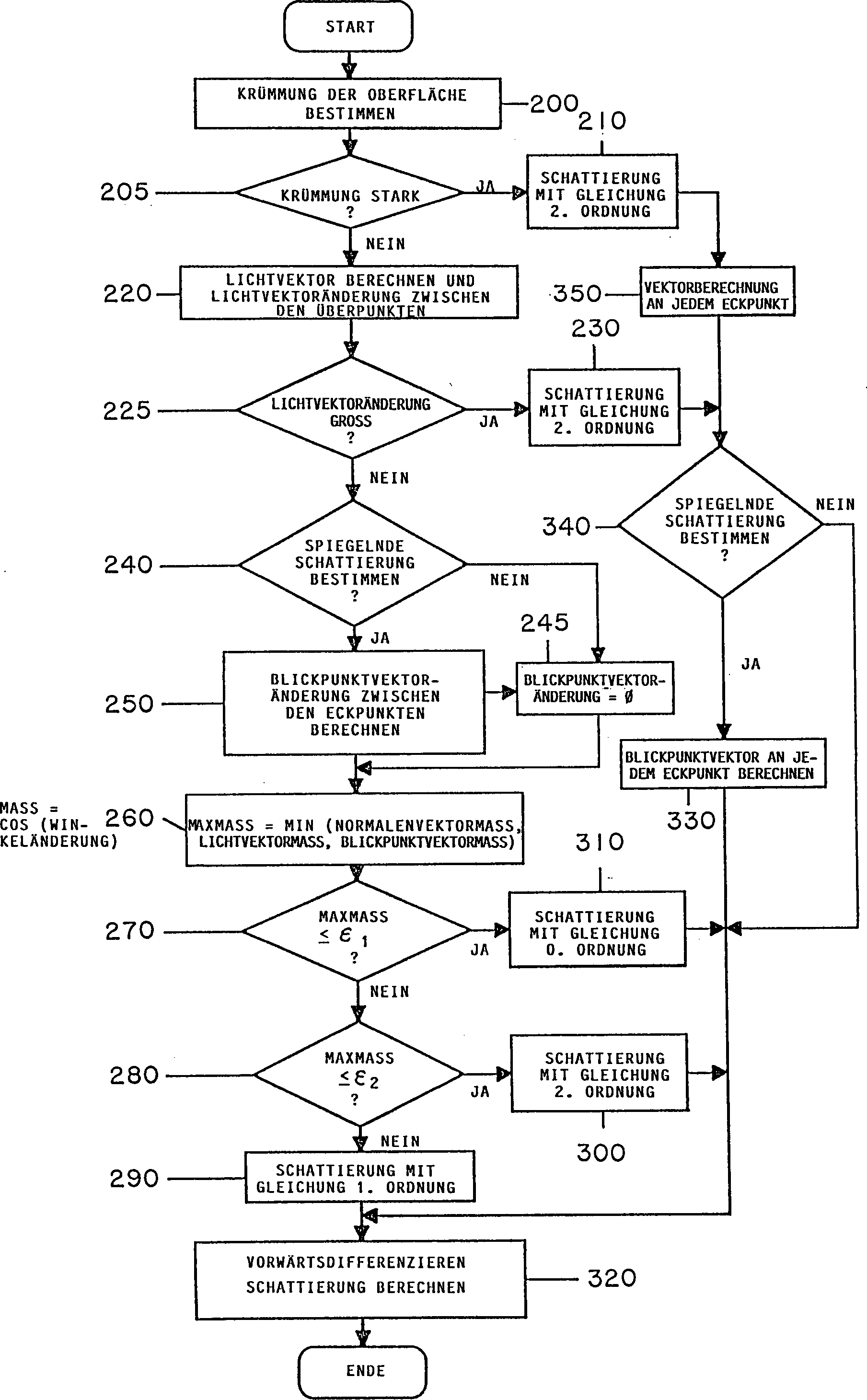
Bei der Erfindung werden die zur Bestimmung des Schattie rungsgrades auf einer Polygonoberfläche verwendeten Schritte der Krümmung des Polygons, der Position der Lichtquelle in bezug auf die Oberfläche des Polygons und der Position des Beobachtungspunktes, d.h. der Position des Auges des Betrachters in bezug auf die Oberfläche des Polygons angepaßt. Je größer die Krümmung des Polygons, je näher die Lichtquelle dem Polygon und je näher der Beobachtungspunkt dem Polygon ist, desto größer ist die Änderung der Reflexion über die Polygonoberfläche und desto mehr Schritte sind erforderlich, um den Schattierungsgrad über die Polygonoberfläche akurat zu bestimmen.at The invention will be used to determine the Schattie degree of efficiency used on a polygon surface Steps of curvature of the polygon, the position of the light source with respect to the surface of the Polygons and the position of the observation point, i. the position of the eye of the observer with respect to the surface of the Polygons adapted. The bigger the curvature of the polygon, the closer the light source the polygon and the closer the observation point the Polygon is the bigger the change the reflection about the polygon surface and the more steps are required to increase the degree of shading over the polygon surface to determine accurately.

Diese Beobachtung wird benutzt, um ein Qualitätsbilder wiedergebendes Verfahren zu schaffen, und zwar ohne den Berechnungs-Mehraufwand zur Erzeugung von Qualitätsbildern bei durchgängiger Nutzung von Schattierungsgleichungen hoher Ordnung. Eine Serie von Tests wird zur Bestimmung des Grades der Krümmung, der Position der Lichtquelle und der Position des Blickpunkts in bezug auf das Polygon ausgeführt. Wenn der Grad der Krümmung gering ist und die Entfernungen der Lichtquelle und des Blickpunkts groß sind, so wird eine einfache, schnelle Gleichung nullter Ordnung benutzt, um die Reflexion über den Polygon zu berechnen. Dies ist möglich, weil das Maß der Reflexion über das Polygon konstant ist, wenn die Änderung des Normalen-Vektors gering ist, was auf eine geringe Oberflächenkrümmung hinweist, und wenn die Änderungen des Lichtquellenvektors und des Blickpunktvektors gering sind. Wenn die Änderung des Maßes der Reflexion gering ist, wenn die Reflexion beispielsweise weniger als 1/250 variiert, so ist die Änderung für den Beobachter beinahe nicht wahrnehmbar, und wenn die Reflexion weniger als 1/64 variiert, so ist die Änderung noch sehr fein. So ist es möglich, die Farbänderung mit einem konstanten Farbwert anzunähern.These Observation is used to provide a quality images reproducing process without the extra computational overhead for generation of quality images with continuous Use of shading equations of high order. A series of Tests are used to determine the degree of curvature, the position of the light source and the position of the viewpoint with respect to the polygon. If the degree of curvature is small and the distances of the light source and the viewpoint are big, so a simple, fast zero-order equation is used about the reflection about to calculate the polygon. This is possible because the measure of reflection on the Polygon is constant when the change of the normal vector is low, indicating a low surface curvature, and if the changes of the Light source vector and the viewpoint vector are low. If the change of measure the reflection is low, for example, if the reflection is less varies as 1/250, so is the change for the Observers almost imperceptible, and when the reflection is less varies as 1/64, so is the change still very fine. So it is possible the color change to approximate with a constant color value.

Wenn das Maß der Reflexionsänderung über das Polygon wächst, wird eine Gleichung höherer Ordnung zur Berechnung der Reflexion über das Polygon benutzt. Dies erzeugt eine genauere Wiedergabe der Reflexion, welche mit einer Gleichung nullter Ordnung nicht erreicht werden kann. Wenn das Maß der Krümmung größer wird und/oder die Lichtquelle näherkommt, so daß sich der Richtungsvektor von den Eckpunkten des Polygons zur Lichtquelle von Eckpunkt zu Eckpunkt ändert, so wird eine Gleichung höherer Ordnung benutzt. Weil das Maß der Reflexion sich über die Oberfläche des Polygons signifikant ändert, so daß sie für den Beobachter wahrnehmbar ist und somit der Grad des Schattierens über das Polygon nicht konstant ist, muß eine rechenzeitintensive Gleichung höherer Ordnung benutzt werden, um ein Qualitätsbild wiederzugeben.As the amount of reflection change increases across the polygon, a higher order equation is used to compute the reflection over the polygon. This produces a more accurate reflection of the reflection, which can not be achieved with a zero-order equation. If the measure of Krüm As the flux increases and / or approaches the light source so that the direction vector changes from the vertices of the polygon to the light source from vertex to vertex, a higher order equation is used. Because the amount of reflection changes significantly across the surface of the polygon so that it is perceptible to the observer and thus the degree of shading across the polygon is not constant, a higher-order computation-intensive equation must be used to render a quality image.

Die 4a, 4b und 4c stellen drei Situationen dar, in denen Gleichungen nullter Ordnung und erster Ordnung zur Bestimmung der Reflexion nicht adäquat sind. In 4a wird angenommen, daß die Oberflächenkrümmung über dem Dreieck groß ist. Somit variieren die Eckpunkt-Normalenvektoren N und die diffuse Reflexion, welche proportional zur Projektion des Eckpunkt-Normalenvektors auf den Eckpunkt-Lichtquellenvektor L ist. So ist es wünschenswert, eine Gleichung mit einer Ordnung auszuwählen, die diese Reflexionsänderung berücksichtigt. In diesem Beispiel würde die Gleichung erster Ordnung nicht adäquat sein, und das System würde die Gleichung der nächsthöheren Ordnung (Phong) auswählen, um die Reflexion zu simulieren. Es sollte angemerkt werden, daß die Phong-Gleichung strenggenommen keine Gleichung zweiter Ordnung ist. Die Methode schließt eine Normierung ein, welche eine Quadratwurzel und eine Division an jedem Pixel erfordert. In der Literatur wird jedoch angegeben, daß Gleichungen zweiter Ordnung diese Lösung annähern (siehe Weimer, "Fast Phong Shading", Computer Graphics, Bd. 20, Nr. 4 (1986) Seiten 103–105). Soweit nicht anders angegeben, wird die Phong-Gleichung in der Beschreibung als eine Gleichung zweiter Ordnung bezeichnet.The 4a . 4b and 4c represent three situations in which equations of zeroth order and first order are not adequate for determining the reflection. In 4a It is assumed that the surface curvature over the triangle is large. Thus, the vertex normal vectors N and the diffuse reflection, which is proportional to the projection of the vertex normal vector on the vertex light source vector L, vary. Thus, it is desirable to select an equation with an order that takes into account this reflection change. In this example, the first order equation would not be adequate, and the system would choose the next higher order equation (Phong) to simulate the reflection. It should be noted that the Phong equation, strictly speaking, is not a second order equation. The method involves normalization which requires a square root and a division at each pixel. However, it is stated in the literature that second order equations approach this approach (see Weimer, "Fast Phong Shading," Computer Graphics, Vol. 20, No. 4 (1986) pp. 103-105). Unless otherwise stated, the Phong equation in the description is referred to as a second order equation.

Es wird angenommen, daß das Dreieck, welches in 4b dargestellt ist, keine Krümmung hat, d.h., daß die Eckpunkt- Normalenvektoren identisch sind, aber daß die Lichtquelle unmittelbar über der Dreiecksoberfläche positioniert ist. Folglich variieren die Eckpunkt-Lichtquellenvektoren und die diffuse Reflexion, welche proportional zur Projektion der Eckpunkt-Normalenvektoren auf die Eckpunkt-Lichtquellenvektoren ist. Eine diese Änderung enthaltene Gleichungsordnung würde dann ausgewählt werden.It is assumed that the triangle which is in 4b is shown to have no curvature, that is, that the vertex normal vectors are identical, but that the light source is positioned immediately above the triangular surface. Thus, the vertex light source vectors and the diffuse reflection, which is proportional to the projection of the vertex normal vectors on the vertex light source vectors, vary. An equation order containing this change would then be selected.

In 4c wird angenommen, daß das Dreieck keine Krümmung hat, aber die Blickpunktposition unmittelbar über der Dreiecksoberfläche ist. Somit variieren die Eckpunkt-Blickpunktvektoren und die spiegelnde Reflexion, welche die Projektion der Eckpunkt-Normalenvektoren auf die Eckpunkt-Blickpunktvektoren enthält. Das System der Erfindung würde diese Situation erkennen und eine Gleichungsordnung auswählen, welche die Reflexionsänderung enthält.In 4c It is assumed that the triangle has no curvature, but the viewpoint position is immediately above the triangle surface. Thus, the vertex viewpoint vectors and the specular reflection, which includes the projection of the vertex normal vectors on the vertex viewpoint vectors, vary. The system of the invention would recognize this situation and select an equation ordering containing the reflection change.

Somit balanciert das System die Vorteile der schnellen, billigen Berechnungen mit Bildern geringerer Qualität und der langsamen, teureren Berechnungen mit Bildern hoher Qualität aus. Schnelle, billige Berechnungen werden vorzugsweise benutzt, um das Maß der Reflexion auf einem Polygon zu bestimmen; wenn jedoch die Krümmung des Polygons, die Position der Lichtquelle oder die Position des Blickpunkts eine signifikante Reflexionsänderung über die Oberfläche anzeigen, so wird eine Gleichung höherer Ordnung benutzt, um ein Qualitätsbild wiederzugeben. Somit werden die langsameren, kostenintensiveren Berechnungen höherer Ordnung nur soweit nötig ausgeführt. Die Polygone mit geringer Krümmung, großen Entfernungen zur Lichtquelle und großen Entfernungen zum Blickpunkt werden unter Nutzung von Gleichungen niedrigerer Ordnung schnell und unaufwendig berechnet. Es wurde gefunden, daß ein wesentlicher Teil der ein Bild bildenden Polygone durch Nutzung einer Gleichung nullter oder erster Ordnung wiedergegeben werden kann. Bilder, die mit Hilfe des anpassungsfähigen Schattierungssystems der Erfindung wiedergegeben werden, werden mit geringer oder nicht wahr nehmbarer Verringerung der Bildqualität 20 bis 50 % schneller erzeugt, als durch Gleichungen hoher Ordnung wiedergegebene Bilder.Consequently the system balances the benefits of fast, cheap calculations with images of lower quality and the slower, more expensive calculations with high quality images. fast, Cheap calculations are preferably used to measure the amount of reflection to determine on a polygon; however, if the curvature of the Polygons, the position of the light source or the position of the viewpoint a significant reflection change over the surface show, a higher order equation is used to make a quality image play. Thus, the slower, more costly Calculations higher Order only as necessary executed. The polygons with low curvature, huge Distances to the light source and long distances to the viewpoint become fast using equations of lower order and inexpensively calculated. It has been found that an essential part of forming an image forming polygons by using an equation zeroth or first order can be reproduced. Pictures with the help the adaptive Shading system of the invention are reproduced with low or unacceptable image quality reduction 20 to Generated 50% faster than reproduced by equations of high order Images.

Im bevorzugten Ausführungsbeispiel können drei Typen von Gleichungen benutzt werden, um das Maß der Reflexion über ein Polygon zu berechnen: Gleichungen nullter Ordnung, erster Ordnung und zweiter Ordnung. Die Gleichung nullter Ordnung berechnet einen konstanten Wert für die gesamte Polygonoberfläche. Vorzugsweise folgt die Gleichung nullter Ordnung dem Lambert'schen Gesetz und berechnet das Gewicht der diffusen Reflexion gemäß der Gleichung: cos(α) = N·L,wobei N die Oberflächennormale und L der Lichtquellenvektor ist. Die Normale kann eine Eckpunktnormale oder eine Normale an einem beliebigen Punkt auf der Oberfläche sein. Vorzugsweise ist die Normale die gemittelte Normale der Eckpunktnormalen.In the preferred embodiment, three types of equations may be used to calculate the amount of reflection over a polygon: zero order, first order, and second order equations. The zero-order equation calculates a constant value for the entire polygon surface. Preferably, the zero-order equation follows Lambert's law and calculates the weight of the diffuse reflection according to the equation: cos (α) = N · L, where N is the surface normal and L is the light source vector. The normal may be a vertex normal or a normal at any point on the surface. Preferably, the normal is the average normal of the vertex normals.

Eine Gleichung erster Ordnung wird vorzugsweise gemäß der Gouraud-Schattierungsmethode berechnet. Die Gouraud-Methode erzeugt ein Bild von adäquater Qualität, wenn die Änderung der Reflexion über die Polygonoberfläche gering ist. Wenn die Änderung der Reflexion über die Polygonoberfläche signifikant ist, was auf die Notwendigkeit der Verwendung einer Gleichung zweiter Ordnung, hinweist, wird vorzugsweise die Phong-Schattierungsmethode benutzt.A first order equation is preferably calculated according to the Gouraud shading method. The Gouraud method produces an image of adequate quality if the change in reflection over the polygon surface is small. If the change in reflection over the polygon surface is significant, indicating the necessity of using a second order equation, the Phong shading method is preferably used.

Im folgenden wird das Verfahren der Erfindung anhand der 5, 6a und 6b beschrieben. 5 stellt den Ablauf des Verfahrens in bezug auf ein erstes Ausführungsbeispiel der Erfindung dar, und die 6a und 6b stellen den Ablauf des Verfahrens in bezug auf ein anderes Ausführungsbeispiel der Erfindung dar. Die bevorzugten Ausführungsbeispiele werden anhand von Bildwiedergaben beschrieben, die die Abtastzeilen-Technik (scan line technique) benutzen. Für den Fachmann ist es jedoch offensichtlich, daß die Erfindung nicht nur bei der Abtastzeilen-Technik, sondern auch bei anderen Techniken, wie beispiels weise Ebenengleichungen, angewendet werden kann, um die Farbe an den Polygoneckpunkten oder andere Randbedingungen über das Polygon zu interpolieren.In the following, the method of the invention with reference to 5 . 6a and 6b described. 5 illustrates the process of the method with respect to a first embodiment of the invention, and the 6a and 6b illustrate the flow of the method with respect to another embodiment of the invention. The preferred embodiments will be described in terms of image rendering using the scan line technique. However, it will be apparent to those skilled in the art that the invention can be applied not only to scanline technique but also to other techniques, such as level equations, for interpolating the color at the polygon vertices or other boundary conditions across the polygon.

Wenn die Abtastzeilen-Technik benutzt wird, werden die Displayelemente, die das Polygon für jede Abtastzeile bzw. -linie schneidet, bestimmt und die Farbe jedes dieser Displayelemente aus den Eckpunkt-Attributen (Farbe, Position und Normale) abgeleitet, wobei bekannte Schattierungsgleichungen, wie beispielsweise die oben beschriebenen Gleichungen nullter, erster oder zweiter Ordnung, benutzt werden. Um die Eckpunkt-Attribute (oder andere Randbedingungen) über die Displayelemente, die das Polygon schneidet, zu interpolieren, werden Differenzvariable bestimmt. Die Differenzvariablen bestimmen, wie die Eckpunkt-Attribute (Tiefe, Normale, Farbe) entlang der Polygonkanten und über die Abtastlinie zwischen den Polygonkanten zu inkrementieren sind. Wie unten dargestellt, wird in den meisten Fällen die Normalendifferenzvariable (ebenso wie die der Farbe und der Position) bestimmt. Wenn jedoch die hier beschriebenen Testkriterien anzeigen, daß der Lichtvektor und/oder der Blickpunktvektor variieren, so werden die Differenzvariablen für diese Vektoren in der gleichen Weise wie für die Normalendifferenzvariable bestimmt und die Attribute über das Polygon interpoliert.If the scanning line technique is used, the display elements, the polygon for each scan line intersects, determines, and the color of each these display elements from the vertex attributes (color, position and normal), where known shading equations, such as the equations zeroth, first described above or second order. To the vertex attributes (or other constraints) about to interpolate the display elements that intersect the polygon, Difference variables are determined. Determine the difference variables like the vertex attributes (depth, Normal, color) along the polygon edges and across the scan line between to increment the polygon edges. As shown below, in most cases the normal difference variable (as well as the color and the Position). However, if the test criteria described here show that the Light vector and / or the viewpoint vector vary, so are the Difference variables for these vectors in the same way as for the normal difference variable determined and attributes over the polygon interpolates.

Bezugnehmend auf die 7a und 7b werden zuerst die Differenzvariablen für die Position, die Normale und die Farbe wie folgt bestimmt.

Figure 00170001
Figure 00180001
wobei dPx(1), dPy(1), dPz(1) die Positionsdifferenzvariablen für die Kante zwischen dem ersten und dem zweiten Eckpunkt, dPx(2), dPy(2), dPz(2) die Positionsdifferenzvariablen für die Kante zwischen dem ersten und dem dritten Eckpunkt und dPx(3), dPy(3), dPz(3) die Positionsdifferenzvariablen für die Kante zwischen dem dritten und dem ersten Eckpunkt sind. Die Variablen dNx(1), dNy(1), dNz(1) stellen die Normalendifferenzvariablen für die Normalen am ersten und am zweiten Eckpunkt, dNx(2), dNy(2), dNz(2) die Normalendifferenzvariablen für die Normalen am zweiten und am dritten Eckpunkt und dNx(3), dNy(3), dNz(3) die Normalendifferenzvariablen für die Normalen am dritten und am ersten Eckpunkt dar. Die Variablen dCr(1), dCg(1), dCb(1) stellen die Farbdifferenzvariablen entlang der Kante zwischen der ersten und dem zweiten Eckpunkt, dCr(2), dCg(2) und dCb(2) die Farbdifferenzvariablen entlang der Kante zwischen dem zweiten und dem dritten Eckpunkt und dCr(3), dCg(3) und dCb(3) die Farbdifferenzvariablen entlang der Kante zwischen dem dritten und dem ersten Eckpunkt dar.Referring to the 7a and 7b First the difference variables for the position, the normals and the color are determined as follows.
Figure 00170001
Figure 00180001
where dPx (1), dPy (1), dPz (1) are the position difference variables for the edge between the first and second vertices, dPx (2), dPy (2), dPz (2) the position difference variables for the edge between the first and the third vertex and dPx (3), dPy (3), dPz (3) are the position difference variables for the edge between the third and the first vertex. The variables dNx (1), dNy (1), dNz (1) represent the normal difference variables for the normals at the first and second vertices, dNx (2), dNy (2), dNz (2) the normal difference variables for the normals at the second and at the third vertex and dNx (3), dNy (3), dNz (3) represent the normal difference variables for the normals at the third and the first vertex. The variables dCr (1), dCg (1), dCb (1) represent the Color difference variables along the edge between the first and second vertexes, dCr (2), dCg (2) and dCb (2) the color difference variables along the edge between the second and third vertexes and dCr (3), dCg (3) and dCb (3) the color difference variable along the edge between the third and the first vertex.

Aus dem Betrag der Positionsdifferenzvariablen (dPx gegenüber dPy) kann die Hauptachse bestimmt werden. Die Hauptachse zeigt die Richtung an, in welcher die Kanten des Polygons wiedergegeben werden. In der vorliegenden Darstellung ist die Y-Achse die Hauptachse für die erste Kante und für die zweite Kante und die X-Achse die Hauptachse für die dritte Kante. Die Positionsdifferenzvariable für die Nebenachse wird durch die Positionsdifferenzvariable der Hauptachse dividiert, um das Inkrement für die Nebenachse abzuleiten. Es werden dann Einheitsschritte benutzt, um die Dreieckskanten entsprechend der Abtastlinien-Wiedergabetechnik zu durchlaufen. Die Eckpunkte wer den dann sortiert, um eine linke Kante und eine rechte Kante jeder Abtastlinie zu bestimmen.From the amount of the position difference variable (dPx to dPy), the main axis can be determined. The major axis indicates the direction in which the edges of the polygon are rendered. In the present illustration, the Y-axis is the major axis for the first edge and for the second edge and the X-axis is the major axis for the third edge. The position difference variable for the minor axis is divided by the position difference variable of the major axis to subtract the minor axis increment Unit steps are then used to traverse the triangle edges according to the scan line rendering technique. The vertices are then sorted to determine a left edge and a right edge of each scan line.

Entsprechend der Logik der Abtastlinien-Technik werden die in den Abtastlinien-Gleichungen benutzten Variablen, die die Kanten zwischen den Eckpunkten beschreiben, auf die Eckpunkt-Attribute als Anfangswerte eingestellt, und aus den Differenzvariablen abgeleitete Schrittweitevariablen werden benutzt, um das Polygon zu durchlaufen. Die Positionsdifferenzvariablen ergeben nach der Division durch die Hauptachse normierte Positionsinkremente, die Normalendifferenzvariablen nach der Division durch die Hauptachse normierte Normaleninkremente und die Farbdifferenzvariablen nach Division durch die Hauptachse normierte Farbinkremente:

Figure 00190001
According to the logic of the scan line technique, the variables used in the scan line equations describing the edges between the vertices are set to the vertex attributes as initial values, and step variables derived from the difference variables are used to traverse the polygon. The position difference variables provide normalized position increments after division by the major axis, the normal difference variables after normal axis normalized normal division increments, and the color difference variables after normalized color increments after division by the major axis:
Figure 00190001

Die Inkrementwerte werden dann benutzt, um mit Hilfe einer Kanteninterpolationslogik die Eckpunkt-Attribute entlang der Dreieckskanten zu interpolieren:

Figure 00190002
Figure 00200001
The increment values are then used to interpolate the vertex attributes along the triangle edges using edge interpolation logic:
Figure 00190002
Figure 00200001

Um das Polygon zu durchlaufen, werden die Eckpunkt-Attribute interpoliert, um Werte an der linken Seite und der rechten Seite der Abtastzeile zu erzeugen (siehe 7c). Um die Abtastzeile bzw. -linie auszufüllen, werden zuerst die Differenzvariablen für die Abtastlinie bestimmt. Die Differenzvariablen für die Abtastlinie gemäß 7d sind:

Figure 00200002
To traverse the polygon, the vertex attributes are interpolated to produce values at the left side and the right side of the scan line (see 7c ). To fill the scan line, the difference variables for the scan line are first determined. The difference variable for the scan line according to 7d are:
Figure 00200002

Die Variablen werden dann durch die Breite der Abtastlinie, d.h. dPx(y), dividiert, um die Variablen zu normieren und einheitliche Schrittvariablen für die Abtastlinie zu erzeugen (vorzugsweise angepaßt an die einheitlichen Inkremente des Rasters):

Figure 00200003
The variables are then divided by the width of the scan line, ie dPx (y), to normalize the variables and generate uniform step variables for the scan line (preferably matched to the uniform increments of the raster):
Figure 00200003

Mit dieser Information werden dann die Eckpunkt-Attribute über das Dreieck interpoliert, um das Dreieck auszufüllen:

Figure 00200004
Figure 00210001
This information then interpolates the vertex attributes across the triangle to fill the triangle:
Figure 00200004
Figure 00210001

Die Lösung erster Ordnung der Reflexionsgleichung vereinfacht den Wiedergabeprozeß. Anders als bei Lösungen höherer Ordnung entfernt die Lösung erster Ordnung die Notwendigkeit, die Differenzgleichungen für den Normalenvektor zu bestimmen. Stattdessen werden die Gewichte der diffusen Reflexion an den Eckpunkten (1, 2, 3) bestimmt: cos(α1): = Lx(1)·Nx(1) + Ly(1)·Ny(1) + Lz(1)·Nz(1) cos(α2): = Lx(2)·Nx(2) + Ly(2)·Ny(2) + Lz(2)·Nz(2) cos(α3): = Lx(3)·Nx(3) + Ly(3)·Ny(3) + Lz(3)·Nz(3) The first order solution of the reflection equation simplifies the rendering process. Unlike higher order solutions, the first order solution removes the need to determine the difference equations for the normal vector. Instead, the weights of the diffuse reflection at the vertices (1, 2, 3) are determined: cos (α1): = Lx (1) · Nx (1) + Ly (1) · Ny (1) + Lz (1) · Nz (1) Cos (α2): = Lx (2) * Nx (2) + Ly (2) * Ny (2) + Lz (2) * Nz (2) Cos (α3): = Lx (3) · Nx (3) + Ly (3) · Ny (3) + Lz (3) · Nz (3)

Die diffusen Gewichte werden dann in jedes der Eckpunkt-Farbattribute aufgenommen. Cr(1) = (Kar + Kdr·cos(α1))·Cr(1) Cg(1) = (Kag + Kdg·cos(α1))·Cg(1) Cb(1) = (Kab + Kdb·cos(α1))·Cb(1) Cr(2) = (Kar + Kdr·cos(α2))·Cr(2) Cg(2) = (Kag + Kdg·cos(α2))·Cg(2) Cb(2) = (Kab + Kdb·cos(α2))·Cb(2) Cr(3) = (Kar + Kdr·cos(α3))·Cr(3) Cg(3) = (Kag + Kdg·cos(α3))·Cg(3) Cb(3) = (Kab + Kdb·cos(α3))·Cb(3) The diffuse weights are then included in each of the vertex color attributes. Cr (1) = (Ka r + Kd r * Cos (α1)) · Cr (1) Cg (1) = (Ka G + Kd G * Cos (α1)) · Cg (1) Cb (1) = (Ka b + Kd b * Cos (α1)) · Cb (1) Cr (2) = (Ka r + Kd r * Cos (α2)) · Cr (2) Cg (2) = (Ka G + Kd G * Cos (α2)) · Cg (2) Cb (2) = (Ka b + Kd b * Cos (α2)) · Cb (2) Cr (3) = (Ka r + Kd r * Cos (α3)) · Cr (3) Cg (3) = (Ka G + Kd G * Cos (α3)) · Cg (3) Cb (3) = (Ka b + Kd b * Cos (α3)) · Cb (3)

Es sollte angemerkt werden, daß die o.g. Gleichungen die diffuse Reflexion für eine Lichtquelle beschreiben. Gibt es mehrere Lichtquellen, so summiert die Lösung die diffusen Reflexionen, da die Beiträge additiv sind.It It should be noted that the above-mentioned Equations describing diffuse reflection for a light source. If there are several light sources, the solution sums up the diffuse reflections, because the posts are additive.

In der Lösung erster Ordnung werden die Positionsdifferenzvariablen und die Farbdifferenzvariablen wie oben dargelegt be stimmt. Es gibt keine Notwendigkeit die Normalendifferenzvariablen zu bestimmen. Die Eckpunktfarbwerte begründen die diffusen Gewichtswerte. Ein Problem, welches mit dieser Lösung entsteht, ist jedoch, daß die diffusen Gewichte unterschätzt werden können. Eine Lösung zweiter Ordnung korrigiert dies durch Nutzung der Normalendifferenzvariablen. Wie oben beschrieben werden die Normalenvektoren an den Eckpunkten zuerst entlang der Polygonkante interpoliert und dann auf ihren Betrag normiert. Der Normalenvektor wird dann entlang der Abtastlinie des Polygons zwischen der linken und der rechten Polygonkante inkrementiert und ist an jedem Displayelement normiert.In the solution first order, the position difference variables and the color difference variables are like stated above be true. There is no need for the normal difference variables to determine. The vertex color values justify the diffuse weight values. However, one problem that arises with this solution is that the underestimated diffuse weights can be. A solution second order corrects this by using the normal difference variables. As described above, the normal vectors are at the vertices first interpolated along the polygon edge and then onto your polygon edge Amount normalized. The normal vector then becomes along the scan line of the polygon increments between the left and right polygon edges and is normalized on each display element.

Dieser Normalenvektor wird dann benutzt, um das diffuse Gewicht an jedem Displayelement zu berechnen: cos(α(x,y)): = Lx(x,y)·Nx(x,y) + Ly(x,y)·Ny(x,y) + Lz(x,y)·Nz(x.y)und das diffuse Gewicht wird in den Farbwert aufgenommen: Cr(x,y): = (Kar + Kdr·cos(α(x,y)))Cr(x,y) Cg(x,y): = (Kag + Kdg·cos(α(x,y)))·Cg(x,y) Cb(x,y): = (Kab + Kdb·cos(α(x,y)))·Cb(x,y) This normal vector is then used to calculate the diffuse weight on each display element: cos (α (x, y)): = Lx (x, y) x Nx (x, y) + Ly (x, y) x Ny (x, y) + Lz (x, y) x Nz (xy) and the diffuse weight is added to the color value: Cr (x, y): = (Ka r + Kd r · Cos (α (x, y))) Cr (x, y) Cg (x, y): = (Ka G + Kd G · Cos (α (x, y))) · Cg (x, y) Cb (x, y): = (Ka b + Kd b · Cos (α (x, y))) * Cb (x, y)

Die o.g. Gleichungen nehmen an, daß der Lichtvektor L(x,y) sich über das Polygon nicht ändert. Wenn sich der Lichtvektor tatsächlich ändert, so muß der Lichtvektor ebenso wie der Normalenvektor interpoliert und normiert werden. Die zusätzlichen Interpolationen und Normierungen sind zeitraubend und aufwendig. Das System der vorliegenden Erfindung vereinfacht die Reflexionsgleichung in dreierlei Hinsicht. Erstens bestimmt das System der Erfindung, wann Lösungen nullter, erster oder zweiter Ordnung anzuwenden sind, so daß die aufwendigen Lösungen hoher Ordnung nur dann benutzt werden, wenn es die Normalenvektoränderung, Lichtvektoränderung oder Blickpunktvektoränderung aktuell erfordern. Zweitens kann das System der Erfindung wahlweise erkennen, welche speziellen Vektorwerte eine Interpolation erfordern, indem es bestimmt, welche Vektoren sich signi fikant über das Polygon ändern, und somit die zeitraubende Interpolation der drei Vektorwerte (einschließlich jener, die keine Interpolation erfordern) vermeiden. Zusätzlich kann das System der Erfindung wahlweise gewöhnliche Differenzengleichungen einsetzen, um die Farbwerte zu interpolieren. Diese Option vermeidet die aufwendigere klassische Lösung, welche die drei Vektoren interpoliert und normiert.The above-mentioned Equations assume that the Light vector L (x, y) over the polygon does not change. If the light vector actually changes, so must the Light vector as well as the normal vector interpolated and normalized become. The additional Interpolations and normalizations are time-consuming and expensive. The system of the present invention simplifies the reflection equation in three ways. First, the system of the invention determines when solutions zeroth, first or second order apply, so that the elaborate solutions high order can only be used if it is the normal vector change, light vector change or viewpoint vector change currently require. Second, the system of the invention may optionally recognize which special vector values require interpolation, by determining which vectors are significant over the Change polygon, and thus the time-consuming interpolation of the three vector values (including those avoid interpolation). In addition, can the system of the invention optionally has ordinary difference equations use to interpolate the color values. This option avoids the more elaborate classic solution, which interpolates and normalizes the three vectors.

Bezugnehmend auf 5 wird im folgenden das Verfahren der Erfindung erläutert. Am Block 200 wird die Krümmung über die Oberfläche bestimmt. Sie wird in bezug auf die Normalen an jedem Eckpunkt des Polygons und entsprechend dem von den Normalen bestimmten Grad der Krümmung bestimmt, indem die Krümmungsgrade zwischen Paaren von Eckpunkten verglichen werden, um festzustellen, ob die Krümmung über dem Polygon stark ist. Vorzugsweise werden die folgenden Gleichungen benutzt (siehe 8a): cos(ϕ) = min(cos(ϕ1)), cos(ϕ(2)), cos(ϕ(3)))wobei cos(ϕ(1)) = Nx(1)·Nx(2) + Ny(1)·Ny(2) + Nz(1)·Nz(2) cos(ϕ(2)) = Nx(2)·Nx(3) + Ny(2)·Ny(3) + Nz(2)·Nz(3) cos(ϕ(3)) = Nx(3)·Nx(1) + Ny(3)·Ny(1) + Nz(3)·Nz(1) Referring to 5 The method of the invention will be explained below. At the block 200 the curvature over the surface is determined. It is determined with respect to the normals at each vertex of the polygon and according to the degree of curvature determined by the normals by comparing the degrees of curvature between pairs of vertices to determine if the curvature is strong across the polygon. Preferably, the following equations are used (see 8a ): cos (φ) = min (cos (φ1)), cos (φ (2)), cos (φ (3))) in which cos (φ (1)) = Nx (1) * Nx (2) + Ny (1) * Ny (2) + Nz (1) * Nz (2) cos (φ (2)) = Nx (2) * Nx (3) + Ny (2) * Ny (3) + Nz (2) * Nz (3) cos (φ (3)) = Nx (3) * Nx (1) + Ny (3) * Ny (1) + Nz (3) * Nz (1)

Der cos(ϕ)-Wert ist ein Maß für die maximale Abweichung zwischen den Eckpunkt-Normalenvektoren. Er sagt die maximale Krümmung des Polygons voraus. Wenn am Block 205 der cos(ϕ)-Wert eine starke Krümmung anzeigt, so wird am Block 210 eine Schattierungsgleichung zweiter Ordnung implementiert, anderenfalls wird der cos(ϕ)-Wert gespeichert, um nachfolgend im Verfahren verwendet zu werden.The cos (φ) value is a measure of the maximum deviation between the vertex normal vectors. He predicts the maximum curvature of the polygon. When at the block 205 the cos (φ) value indicates a strong curvature, so does the block 210 otherwise, the cos (φ) value is stored to be subsequently used in the method.

Ein vorgegebener Grenzwert wird benutzt, um den Wert von cos(ϕ) zu bestimmen, welcher eine starke Krümmung anzeigt. Der Grenzwert wird vorzugsweise empirisch bestimmt. Der Grenzwert korrespondiert mit der minimalen Krümmung, bei welcher ein Qualitätsbild nur bei Nutzung einer Gleichung zweiter (oder höhe rer) Ordnung erzeugt werden kann. Die Kriterien der Qualität hängen von der Anwendung ab. Wenn beispielsweise cos(α) ungefähr gleich Eins ist, was darauf hinweist, daß L und N parallel sind, und wenn die Kriterien eine Genauigkeit von 8 Bit für den Farb-Term vorsehen, so ergeben sich die Grenzwerte für die Auswahl der Gleichungen nullter, erster und zweiter Ordnung wie folgt:
1,000 < cos(ϕ) < 0,996: nullte Ordnung,
0,996 < cos(ϕ) < 0,992: erste Ordnung,
0,992 < cos(ϕ) < 0: zweite Ordnung.
A predetermined threshold is used to determine the value of cos (φ), which indicates a large curvature. The threshold is preferably determined empirically. The threshold corresponds to the minimum curvature at which a quality image can only be generated using a second (or higher) order equation. The criteria of quality depend on the application. For example, if cos (α) is approximately equal to one, indicating that L and N are parallel, and if the criteria provide 8-bit precision for the color term, then the limits for selecting equations zero are, first and second order as follows:
1.000 <cos (φ) <0.996: zeroth order,
0.996 <cos (φ) <0.992: first order,
0.992 <cos (φ) <0: second order.

Vorzugsweise ist der Grenzwert durch den Benutzer modifi zierbar, um das Verfahren den Kundenwünschen für jede benutzte Anwendung und jedes erzeugte Bild anzupassen. Wenn typischerweise cos(ϕ) annähernd den Wert Eins hat, so ist die Krümmung über das Polygon gering und der Verfahrensablauf wird mit dem Block 220 fortgesetzt. Wenn die Krümmung stark ist und anzeigt, daß eine schnelle Schattierungsgleichung geringer Ordnung nicht die gewünschte Qualität im Bild liefern würde, so wird ein präziseres, aber zeitraubendes und teures Schattierungsverfahren hoher Ordnung benutzt. Wenn natürlich der Benutzer ein schnell erzeugtes Bild fordert und keine Anforderungen an die Qualität stellt, so kann der Grenzwert auf einen niedrigeren Wert gesetzt werden, um einen größeren Prozentsatz der Polygone des Bildes mit einer Gleichung nullter Ordnung zu erzeugen. Wenn beispielsweise die Kriterien eine Einhaltung einer Genauigkeit von 4 Bit für den Farb-Term fordern, so ergeben sich die Grenzwerte für die Auswahl der Gleichung nullter, erster und zweiter Ordnung wie folgt:
1,000 < cos((ϕ) < 0,938: nullte Ordnung
0,938 < cos(ϕ) < 0,879: erste Ordnung
0,879 < cos(ϕ) < 0: zweite Ordnung.
Preferably, the limit is modifiable by the user to tailor the method to the customer's wishes for each application used and each image produced. Typically, when cos (φ) is approximately unity, the curvature across the polygon is small and the process proceeds with the block 220 continued. If the curvature is strong, indicating that a fast, low-order shading equation would not provide the desired quality in the image, then a more precise, but more timely consuming and expensive high-order shading method used. Of course, if the user requires a fast generated image and does not set quality requirements, the threshold may be set to a lower value to produce a larger percentage of the polygons of the image with a zero order equation. For example, if the criteria requires compliance with 4-bit accuracy for the color term, then the limits for selecting the zeroth, first, and second order equations are as follows:
1.000 <cos ((φ) <0.938: zeroth order
0.938 <cos (φ) <0.879: first order
0.879 <cos (φ) <0: second order.

In ähnlicher Weise kann, wenn der Benutzer ein präzise schattiertes Bild fordert, der Grenzwert auf einen Wert, der näher an Eins liegt, gesetzt werden, um einen größeren Prozent satz der Polygone mit einer Schattierungsgleichung höherer Ord nung wiederzugeben. Wenn die Krümmung nicht stark ist, wird im Block 220 die Positionsänderung der Lichtquelle in bezug auf die Eckpunkte bestimmt.Similarly, if the user requires a precisely shaded image, the threshold may be set to a value closer to one to reflect a larger percentage of the polygons with a higher order shading equation. If the curvature is not strong, is in the block 220 determines the change in position of the light source with respect to the vertices.

Die Richtung des Lichts wird sich relativ zu einem Eckpunkt um so mehr ändern, je näher die Lichtquelle dem Polygon ist. Bei einer im Unendlichen liegenden Lichtquelle, ist die Lichtquellenrichtung für alle Eckpunkte die gleiche. Bei einer in endlicher Entfernung angeordneten Lichtquelle, wie sie in 8b dargestellt ist, wird die Änderung der Lichtquellenanordnung zwischen den Eckpunkten wie folgt bestimmt: cos(ψ) = min(cos(ψ(1)), cos(ψ(2)), cos(ψ(3)))wobei cos(ψ(1)) = Lx(1)·Lx(2) + Ly(1)·Ly(2) + Lz(1)·Lz(2) cos(ψ(2)) = Lx(2)·Lx(3) + Ly(2)·Ly(3) + Lz(2)·Lz(3) cos(ψ(3)) = Lx(3)·Lx(1) + Ly(3)·Ly(1) + Lz(3)·Lz(1)wobei Lx, Ly, Lz die Positionen der Lichtquelle in bezug auf den Eckpunkt darstellen.The direction of the light will change relative to a vertex the more the closer the light source is to the polygon. For an infinite light source, the light source direction is the same for all vertices. In a finite distance light source, as in 8b is shown, the change of the light source arrangement between the vertices is determined as follows: cos (ψ) = min (cos (ψ (1)), cos (ψ (2)), cos (ψ (3))) in which cos (ψ (1)) = Lx (1) · Lx (2) + Ly (1) · Ly (2) + Lz (1) · Lz (2) cos (ψ (2)) = Lx (2) · Lx (3) + Ly (2) · Ly (3) + Lz (2) · Lz (3) cos (ψ (3)) = Lx (3) · Lx (1) + Ly (3) · Ly (1) + Lz (3) · Lz (1) where Lx, Ly, Lz represent the positions of the light source with respect to the vertex.

Der cos(ψ)-Wert ist ein Maß für die Abweichung zwischen den Eckpunkt-Lichtvektoren. Wenn der Lichtquellentyp eine unendliche Lichtquelle ist, so hat der cos(ψ)-Wert definitionsgemäß einen Wert von Eins. Wenn am Block 225 gefunden wird, daß die Änderung stark ist, so wird eine Schattierungsgleichung zweiter Ordnung implementiert (Block 230).The cos (ψ) value is a measure of the deviation between the corner point light vectors. If the light source type is an infinite light source, by definition the cos (ψ) value has a value of one. When at the block 225 if the change is found to be strong, then a second order shading equation is implemented (Block 230 ).

Wenn die Reflexionsgleichungen spiegelnde Reflexion enthal ten (Block 240), so werden die Eckpunkt-Blickpunktvektoren (siehe 8c), d.h. die Blickpunktpositionen relativ zu den Eckpunktpositionen, am Block 250 berechnet: cos(η) = min(cos(η(1)), cos(η(2)), cos(η(3)))wobei cos(η(1)) = Lx(1)·Lx(2) + Ly(1)·Ly(2) + Lz(1)·Lz(2) cos(η(2)) = Lx(2)·Lx(3) + Ly(2)·Ly(3) + Lz(2)·Lz(3) cos(η(3)) = Lx(3)·Lx(1) + Ly(3)·Ly(1) + Lz(3)·Lz(1). If the reflection equations contain specular reflection (block 240 ), the vertex viewpoint vectors (see 8c ), ie the viewpoint positions relative to the vertex positions, at the block 250 calculated: cos (η) = min (cos (η (1)), cos (η (2)), cos (η (3))) in which Cos (η (1)) = Lx (1) * Lx (2) + Ly (1) * Ly (2) + Lz (1) * Lz (2) Cos (η (2)) = Lx (2) * Lx (3) + Ly (2) * Ly (3) + Lz (2) * Lz (3) Cos (η (3)) = Lx (3) * Lx (1) + Ly (3) * Ly (1) + Lz (3) * Lz (1).

Die spiegelnde Schattierung enthält die Menge des Glanz lichts einer Oberfläche. Das Glanzlicht (highlight) entspricht direkt der Anordnung der Lichtquelle in bezug auf die Oberfläche und der Anordnung des Auges in bezug auf die Lichtquelle auf der Oberfläche. Wenn die Reflexionsgleichungen nicht die spiegelnde Schattierung umfassen sollen, so wird am Block 245 der cos(η) auf Eins gesetzt, was anzeigt, daß es keine Änderung des Blickpunktvektors gibt.The specular shading contains the amount of gloss of a surface. The highlight directly corresponds to the arrangement of the light source with respect to the surface and the arrangement of the eye with respect to the light source on the surface. If the reflection equations do not include the specular shading, then the block becomes 245 the cos (η) is set to one, indicating that there is no change in the viewpoint vector.

Am Block 260 wird dann die maximale Intensitätsänderung als eine Funktion der Normalenvektoränderung, der Lichtvektoränderung und der Blickpunktvektoränderung bestimmt. Die unten angegebene Funktion wählt beispielsweise den Minimalwert der drei Kosinusmeßwerte aus, wobei die maximale Winkeländerung ausgewählt wird: cos(ϕψη) = min(a(ϕ)·cos(ϕ), a(ψ)·cos(ψ), a(η)·cos(η)) At the block 260 Then, the maximum intensity change is determined as a function of the normal vector change, the light vector change, and the viewpoint vector change. For example, the function below selects the minimum value of the three cosine measurements, with the maximum angle change is selected: cos (φψη) = min (a (φ) · cos (φ), a (ψ) · cos (ψ), a (η) · cos (η))

Die Gewichte a(ϕ), a(ψ), a(η) geben wieder, wie die drei Kosinuswerte die komplette Reflexionsgleichung beeinflussen. Beispielsweise kann eine geringe Änderung in dem cos(η)-Wert in eine große Änderung in der Reflexionsintensität, welche das Auge erreicht, umgesetzt werden. Somit werden die Gewichte benutzt, um die Werte auszubalancieren, so daß eine akkurate Bestimmung der maximalen Änderung ausgeführt werden kann.The Weights a (φ), a (ψ), Give a (η) again, like the three cosines the complete reflection equation influence. For example, a small change in the cos (η) value in a big change in the reflection intensity, which reaches the eye, be implemented. Thus, the weights used to balance the values so that an accurate determination the maximum change accomplished can be.

An den Blöcken 270 und 280 werden durch Vergleichen der maximalen Intensitätsänderung mit Grenzwerten Tests ausgeführt, um zu bestimmen, ob eine Schattierungsgleichung erster oder zweiter Ordnung benutzt werden sollte, um das Schattieren des Polygons zu berechnen. Ein erster und zweiter Grenzwert können empirisch bestimmt oder durch den Benutzer für jede Anwendung entsprechend der gewünschten Qualität des Bildes und der Zeit zur Erzeugung des Bildes eingestellt werden. Vorzugsweise liegt der erste Grenzwert im Bereich von 0,996 bis 0,938 und der zweite Grenzwert im Bereich von 0,992 bis 0,879. Beispielsweise ergibt sich für eine maximale Änderung cos(ϕψη):
1 < cos(ϕψη) < ε1: nullte Ordnung,
ε1 < cos(ϕψη) < ε2: erste Ordnung,
ε2 < cos(ϕψη) < 0: zweite Ordnung.
At the blocks 270 and 280 By comparing the maximum intensity change to threshold values, tests are performed to determine whether a first or second order shading equation should be used to calculate shading of the polygon. First and second limits may be determined empirically or set by the user for each application according to the desired quality of the image and the time to create the image. Preferably, the first threshold is in the range of 0.996 to 0.938 and the second threshold is in the range of 0.992 to 0.879. For example, for a maximum change, cos (φψη) results:
1 <cos (φψη) <ε1: zero order,
ε1 <cos (φψη) <ε2: first order,
ε2 <cos (φψη) <0: second order.

Am Block 270 wird die maximale Intensitätsänderung mit dem ersten Grenzwert ε1 verglichen. Wenn die maximale Intensitätsänderung größer als der erste Grenzwert ist, so wird eine Gleichung nullter Ordnung benutzt (Block 310). Wenn die Änderung kleiner als oder gleich dem ersten Grenzwert ist, so wird am Block 280 die maximale Änderung mit dem zweiten Grenzwert ε2 verglichen. Wenn die maximale Intensitätsänderung kleiner als der zweite Grenzwert ist, so wird die Schattierung unter Nutzung einer Gleichung zweiter Ordnung erzeugt. Wenn nicht, so wird am Block 290 die Schattierung mittels einer Gleichung erster Ordnung ausgeführt. Wenn die Ordnung der zu benutzenden Reflexionsgleichung bestimmt wurde, so werden die Farbwerte entlang der Kanten des Polygons bestimmt, und das Polygon wird wiedergegeben, indem durch Vorwärtsdifferenzieren die Pixel (Anzeigeelemente) auf jeder Abtastlinie, welche das Polygon schneidet, wiedergegeben werden (Block 320).At the block 270 the maximum intensity change is compared with the first limit value ε1. If the maximum intensity change is greater than the first threshold, then a zero-order equation is used (Block 310 ). If the change is less than or equal to the first limit, then the block becomes 280 the maximum change compared with the second threshold ε2. If the maximum intensity change is less than the second threshold, shading is generated using a second order equation. If not, then the block 290 the shading is performed by means of a first-order equation. When the order of the reflection equation to be used has been determined, the color values along the edges of the polygon are determined and the polygon is rendered by forward differentiating the pixels (display elements) on each scan line intersecting the polygon (Block 320 ).

Ein zweites Ausführungsbeispiel der Erfindung wird in den 6a und 6b beschrieben. 6a beschreibt ein Ausführungsbeispiel, welches die diffuse Reflexion enthält. 6b beschreibt ein Ausführungsbeispiel, welches außerdem die spiegelnde Reflexion enthält. Alternativ kann das Ausführungsbeispiel gemäß 6a mit dem Ausführungsbeispiel gemäß 5 kombiniert werden, um ein umfassendes System zur Verfügung zu stellen, welches bei seiner Anwendung die Geschwindigkeit des Ausführungsbeispiels gemäß 6a und die hohe Präzision des Ausführungsbeispiels gemäß 5 nutzt. In ähnlicher Weise kann das Ausführungsbeispiel gemäß 6a mit dem Ausführungsbeispiel gemäß 5 kombiniert werden.A second embodiment of the invention is in the 6a and 6b described. 6a describes an embodiment that contains the diffuse reflection. 6b describes an embodiment which also contains the specular reflection. Alternatively, the embodiment according to 6a with the embodiment according to 5 combined to provide a comprehensive system which, in its application, matches the speed of the embodiment 6a and the high precision of the embodiment according to 5 uses. Similarly, the embodiment according to 6a with the embodiment according to 5 be combined.

Bezugnehmend auf 6a wird am Block 420 die Anordnung der Lichtquelle in bezug auf jeden der Eckpunkte bestimmt. Wenn die Lichtquelle eine positionierte Lichtquelle ist, d.h. eine Lichtquelle, welche einen endlichen Abstand von den Eckpunkten des Polygons hat, so wird die Anordnung der Lichtquelle in be zug auf jeden der Eckpunkte sich ändern. Wenn die Lichtquelle eine unendlich weit entfernte Lichtquelle ist, so wird die Anordnung der Lichtquelle für jeden der Eckpunkte die gleiche sein.Referring to 6a will be at the block 420 determines the arrangement of the light source with respect to each of the vertices. If the light source is a positioned light source, ie a light source having a finite distance from the vertices of the polygon, the arrangement of the light source will change in relation to each of the vertices. If the light source is an infinitely distant light source, the arrangement of the light source will be the same for each of the vertices.

Am Block 430 wird das Punktprodukt des Lichtvektors und der Oberflächennormalen an jedem Eckpunkt bestimmt, und am Block 440 werden die Differenzen zwischen jedem der Punktprodukte an den Eckpunkten berechnet. Am Block 450 wird der Maximalwert cosdiff(α) als maximale Differenz zwischen den Punktprodukten bestimmt: max(abs(cos(α1) – cos(α2)), abs(cos(α2) – cos(α3)), abs(cos(α3) – cos(α1))). At the block 430 the dot product of the light vector and the surface normal is determined at each vertex, and at the block 440 The differences between each of the dot products at the vertices are calculated. At the block 450 the maximum value cos diff (α) is determined as the maximum difference between the dot products: max (abs (cos (α1) - cos (α2)), abs (cos (α2) - cos (α3)), abs (cos (α3) - cos (α1))).

Dieser Wert wird benutzt, um zu bestimmen, ob eine Gleichung nullter, erster, zweiter oder höherer Ordnung benutzt werden soll, um die Schattierung des Polygons zu berechnen. Ein erster Grenzwert τD1 wird benutzt, um zu bestimmen, ob eine Schattierungsgleichung nullter Ordnung benutzt werden soll. Bei Nutzung einer Schattierungsgleichung nullter Ordnung können Zeit und Aufwand gespart werden, wobei noch ein Bild der gewünschten Qualität erzeugt wird. Ein zweiter Grenzwert τD2 wird benutzt, um zu bestimmen, ob eine Schattierungsgleichung zweiter Ordnung benutzt werden sollte.This value is used to determine if a zero, first, second, or higher order equation should be used to calculate the shading of the polygon. A first threshold τ D1 is used to determine if a zero order shading equation should be used. By using a shading equation of zero order time and effort can be saved, while still producing an image of the desired quality. A second threshold τ D2 is used to determine if a second order shading equation should be used.

Die Grenzwerte τD1 und τD2 können empirisch oder auf der Basis der jeweiligen Anwendung bestimmt werden. Wenn beispielsweise ein Benutzer ein Bild mit präziser Schattierung wiederzugeben wünscht, so ist es zweckmäßig, die Schattierung mit einer Reflexionsgleichung zweiter Ordnung zu berechnen. Folglich sollte der Grenzwert τD2 auf einen Wert gesetzt werden, der die Mehrheit der Anzeigeelemente in dem Polygon mit einer Gleichung zweiter Ordnung wiederzugeben veranlaßt. Der Grenzwert τD1 kann auf einen niedrigen Wert und der Grenzwert τD2 kann ebenfalls auf einen niedrigen Wert gesetzt werden, so daß die Schattierung der meisten Polygone des Bildes mit Gleichungen zweiter Ordnung ausgeführt wird. Wenn andererseits der Benutzer eine schnelle Darstellung des Bildes wiederzugeben wünscht und auf die Qualität des Schattierens keinen Wert legt, so können die Grenzwerte τD1 und τD2 zur Erzeugung dieses Effekts eingestellt werden. Insbesondere würden die Grenzwerte τD1 und τD2 auf hohe Werte gesetzt werden, damit die meisten ausgeführten Tests anzeigen, daß die Gleichung nullter Ordnung benutzt wird.The limits τ D1 and τ D2 may be determined empirically or based on the particular application. For example, if a user wishes to render an image with precise shading, it is convenient to compute the shading with a second order reflection equation. Consequently, the threshold τ D2 should be set to a value which causes the majority of the display elements in the polygon to be represented with a second order equation. The threshold τ D1 may be set to a low value and the threshold τ D2 may also be set to a low value so that the shading of most polygons of the image is performed with second order equations. On the other hand, if the user wishes to reproduce a fast representation of the image and does not care about the quality of the shading, the thresholds τ D1 and τ D2 can be set to produce this effect. In particular, the limits τ D1 and τ D2 would be set high so that most of the tests performed indicate that the zero-order equation is being used.

Vorzugsweise werden die Grenzwerte auf Werte gesetzt, welche die Notwendigkeit eines Qualitätsbildes und die Notwendigkeit der schnellstmöglichen Wiedergabe des Bildes ausbalancieren. Außerdem sollten die Grenzwerte berücksichtigen, wie glänzend die Oberfläche ist, d.h. die Strahlbreite der spiegelnden Reflexion. Wenn die Strahlbreite groß ist, wählt die Technik eine Gleichung erster Ordnung. Dies ergibt akzeptable bis für das Auge nahezu perfekte Bilder mit einer Wiedergabegeschwindigkeit, die 25 bis 50 % schneller ist, als die Wiedergabe des gesamten Bildes mit Hilfe der Phong-Schattierungsmethode. Bilder von akzeptabler Qualität wurden ebenfalls erzeugt, wenn die Strahlbreite gering war, obwohl Diskontinuitäten in der Schattierung bestimmter Polygone auftraten, bei welchen ein Polygon mittels einer Gleichung erster Ordnung und ein angrenzendes Polygon mittels einer Gleichung zweiter Ordnung schattiert wurde. Dieses Problem kann jedoch vermieden werden durch die Benutzung kleinerer Polygone. Typischerweise wird in der Praxis die Gleichung nullter Ordnung aufgrund der Notwendigkeit einer Erzeugung von Bildern höherer Qualität nicht häufig benutzt. Folglich wird der Grenzwert τD1 vorzugweise auf einen Wert von ungefähr 0,1 gesetzt, so daß die meisten Polygone mit Gleichungen höherer Ordnung wiedergegeben werden.Preferably, the limits are set to values that balance the need for a quality image and the need for the fastest possible rendering of the image. In addition, the limits should consider how shiny the surface is, ie the beam width of the specular reflection. When the beamwidth is large, the technique chooses a first order equation. This results in acceptable to near-perfect images with a playback speed that is 25 to 50% faster than the entire image playback using the Phong shading method. Images of acceptable quality were also produced when the beam width was small, although discontinuities occurred in the shading of certain polygons in which one polygon was shaded by a first order equation and one adjacent polygon by a second order equation. However, this problem can be avoided by using smaller polygons. Typically, in practice, the zero-order equation is not frequently used because of the need to generate higher quality images. Consequently, the threshold τ D1 is preferably set to a value of about 0.1, so that most polygons are represented by higher order equations.

Ein anderes Ausführungsbeispiel der Erfindung wird anhand von 6b beschrieben. Der Verfahrensablauf ist ähnlich dem in 6a, abgesehen davon, daß die spiegelnde Reflexion zusätzlich zur diffusen Reflexion berücksichtigt ist. Wenn die spiegelnde Reflexion in das Verfahren einbezogen werden soll, so wird am Block 610 der Blickpunktvektor für jeden Eckpunkt berechnet. Die Berechnung normiert jeden Blickpunktvektor auf seinen Betrag. Am Block 620 wird die Projektion des Reflexionsvektors auf den Blickpunktvektor an jedem Eckpunkt bestimmt (R·V). Dieser Wert cos(δ(i)) sagt die spiegelnde Reflexion voraus. Am Block 630 wird die Differenz zwischen den cos(δ(i))-Werten an jedem Eckpunkt berechnet, d.h.:
|cos(δ(1)) – cos(δ(2))|, |cos(δ(2)) – cos(δ(3))|, |cos(δ(3)) – cos(δ(1))|.
Another embodiment of the invention will be described with reference to FIG 6b described. The procedure is similar to that in 6a except that the specular reflection is taken into account in addition to the diffuse reflection. If the specular reflection is to be included in the procedure, then the block 610 the viewpoint vector is calculated for each vertex. The calculation normalizes each viewpoint vector to its amount. At the block 620 the projection of the reflection vector on the viewpoint vector at each vertex is determined (R * V). This value cos (δ (i)) predicts the specular reflection. At the block 630 the difference between the cos (δ (i)) values at each vertex is calculated, ie:
| cos (δ (1)) - cos (δ (2)) |, | cos (δ (2)) - cos (δ (3)) |, | cos (δ (3)) - cos (δ (1 )) |.

Am Block 640 wird die maximale Differenz bestimmt. Wenn die maximale Differenz cosdiff(δ) kleiner als oder gleich dem ersten Grenzwert ist, so wird am Block 650 eine Schattierung nullter Ordnung ausgewählt. Wenn die maximale Differenz cosdiff(δ) größer als oder gleich dem zweiten Grenzwert ist, so wird am Block 670 eine Schattierung zweiter Ordnung ausgewählt. Anderenfalls wird am Block 690 eine Schattierung erster Ordnung benutzt.At the block 640 the maximum difference is determined. If the maximum difference cos diff (δ) is less than or equal to the first limit, then the block 650 selected a shade of zeroth order. If the maximum difference cos diff (δ) is greater than or equal to the second limit, then the block 670 a shade of second order selected. Otherwise, at the block 690 used a shading of first order.

9 stellt eine Tabelle dar, welche die Vorteile der Nutzung des hier beschriebenen Verfahrens illustriert. Die Tabelle zeigt die Ergebnisse des Schattierens desselben Objekts mittels der Phong-Schattierungsmethode, welche eine Gleichung zweiter Ordnung benutzt, der Gouraud-Methode, welche eine Gleichung erster Ordnung benutzt, und der anpassungsfähigen Schattierungstechnik der vorliegenden Erfindung. Die Spiegelkraft ist der Wert, welcher die Reflexionsfähigkeit der Oberfläche anzeigt. Wenn die Spiegelkraft wächst, wächst der Glanz der Oberfläche. Die Wiedergabezeit ist die Zeitspanne, die zur Wiedergabe des Bildes mittels dieser Technik gebraucht wird. "NMSE" ist der normierte mittlere quadratische Fehler zwischen der Pixeldarstellung des durch die adaptive Schattierungsmethode nach der Erfindung erzeugten Bildes und der Phong-Schattierungstechnik zweiter Ordnung. Dieser wurde berechnet mittels der Gleichung:

Figure 00300001
wobei
Pr(i): rote Komponente des i'ten Pixels des über die Phong-Technik erzeugten Bildes;
Pg(i): grüne Komponente des i'ten Pixels des über die Phong-Technik erzeugten Bildes;
Pb(i): blaue Komponente des i'ten Pixels des über die Phong-Technik erzeugten Bildes;
Ar(i): rote Komponente des i'ten Pixels desselben Bildes, erzeugt über die adaptive Schattierung;
Ag(i): grüne Komponente des i'ten Pixels desselben Bildes, erzeugt über die adaptive Schattierung;
Ab(i): blaue Komponente des i'ten Pixels desselben Bildes, erzeugt über die adaptive Schattierung. 9 FIG. 12 illustrates a table illustrating the benefits of using the method described herein. The table shows the results of shading the same object using the Phong shading method using a second order equation, the Gouraud method using a first order equation, and the adaptive shading technique of the present invention. The mirror power is the value that indicates the reflectivity of the surface. As the mirror power grows, the gloss of the surface grows. The playback time is the amount of time it takes to play the picture using this technique. "NMSE" is the normalized mean square error between the pixel representation of the image produced by the adaptive shading method of the invention and the second order Phong shading technique. This was calculated by the equation:
Figure 00300001
in which
Pr (i): red component of the i'th pixel of the Phong-generated image;
Pg (i): green component of the i'th pixel of the phong-generated image;
Pb (i): blue component of the i'th pixel of the phong-generated image;
Ar (i): red component of the i'th pixel of the same image generated via the adaptive shading;
Ag (i): green component of the i'th pixel of the same image generated via the adaptive shading;
From (i): blue component of the i'th pixel of the same image, generated via the adaptive shading.

Je kleiner der NMSE-Wert ist, desto höher ist die Qualität des Bildes. Je geringer somit der Grenzwert τD1 ist, desto besser ist die Qualität des erzeugten Bildes und desto langsamer ist die Wiedergabezeit. Je höher umgekehrt der Grenzwert ist, desto geringer ist die Qualität des erzeugten Bildes und desto schneller ist die Wiedergabezeit unabhängig von der Spiegelkraft, die bei der Wiedergabe des Bildes benutzt wurde. Im allgemeinen ist der normierte mittlere quadratische Fehler (NMSE) eines mit der adaptiven Schattierung erzeugten Bildes kleiner als 0,0001 (verglichen mit einem Phong-erzeugten Bild), was zeigt, daß das Bild annähernd identisch mit dem Phong-schattierten Bild ist. Bilder, die einen NMSE-Wert zwischen 0,0001 und 0,00025 haben, weisen einige kaum sichtbare Schattierungs-Diskontinuitäten auf, währenddessen Bilder, die einen NMSE-Wert zwischen 0,00025 und 0,0005 haben, Schattierungs-Diskontinuitäten aufweisen, welche sichtbar werden. Bilder mit einem NMSE-Wert über 0,0005 weisen deutliche Sprünge oder Brüche auf.The smaller the NMSE value, the higher the quality of the image. Thus, the smaller the threshold τ D1 , the better the quality of the generated image and the slower the reproduction time. The higher the limit is, the lower the quality of the image produced, and the faster the playback time will be regardless of the mirror power used in the playback of the image. In general, the normalized mean square error (NMSE) of an adaptive shading image is less than 0.0001 (compared to a phong generated image), indicating that the image is approximately identical to the phong shaded image. Images that have an NMSE value between 0.0001 and 0.00025 have some barely visible shading discontinuities, while images that have an NMSE value between 0.00025 and 0.0005 have shading discontinuities become visible. Images with an NMSE greater than 0.0005 have significant jumps or breaks.

Die Erfindung ist eindeutig nicht auf irgendeinen speziellen Gleichungstyp zur Berechnung der Schattierung eines Polygons begrenzt. Beim Lesen der Beschreibung wird es für den Fachmann klar, daß jede beliebige bekannte Schattierungsmethode zur Ausführung der Erfindung benutzt werden kann; vorzugsweise werden jedoch die folgenden Gleichungen benutzt. Die Gleichungen benutzen viele der zuvor zur Bestimmung der Ordnung der zu benutzenden Gleichung ausgeführten Berechnungen und sparen somit Zeit in der Ausführung des Schattierungsalgorithmus. Die beschriebenen Berechnungen benutzen die Abtastzeilentechnik, die zuvor für Gleichungen aller Ordnungen beschrieben wurde.The Clearly, the invention is not limited to any particular equation type limited to the calculation of the shading of a polygon. While reading the description will be there for the skilled person that each Any known shading method used to practice the invention can be; however, preferably, the following equations used. The equations use many of the previous ones to determine the Order of the equation to be used executed calculations and save thus time in the execution the shading algorithm. Use the calculations described the scanning line technique previously used for equations of all orders has been described.

Die folgenden Gleichungen benutzen ein einfaches Dreieck, aber die Technik läßt sich auf beliebige Polygone und parametrische Oberflächen ausdehnen. Die Normalenvektoren an speziellen Punkten oder Eckpunkten werden aus den parametrischen Funktionen, welche die Oberfläche definieren, bestimmt (siehe Bartels, Beatty, Barsky: "An Introduction to Splines for Use in Computer Graphics" (Margan Kaufmann, 1987), Seiten 293–299; Faux, Pratt: "Computational Geometry for Design and Manufacture" (Wiley 1979), Seiten 110–113).The following equations use a simple triangle, but the technique let yourself expand to any polygons and parametric surfaces. The normal vectors at special points or vertices are removed from the parametric Functions which the surface define, determined (see Bartels, Beatty, Barsky: "An Introduction to Splines for Use in Computer Graphics "(Margan Kaufmann, 1987), pp. 293-299; Pratt: "Computational Geometry for Design and Manufacture "(Wiley 1979), pages 110-113).

Die Lösung erster Ordnung berechnet die totale Reflexion an den Eckpunkten des Dreiecks. Wenn die Reflexion nur aus der ambienten und der diffusen Reflexion besteht; lauten die Gleichungen: C(1) = (Ka + Kd·cos(α1))·C(1), C(2) = (Ka + Kd·cos(α2))·C(2), C(3) = (Ka + Kd·cos(α3))·C(3),wobei Ka der Koeffizient der ambienten Reflexion, Kd der Koeffizient der diffusen Reflexion und cos(α1) = Lx(1)·Nx(1)+Ly(1)·Ny(1)+Lz(1)·Nz(1), cos(α2) = Lx(2)·Nx(2)+Ly(2)·Ny(2)+Lz(2)·Nz(2), cos(α3) = Lx(3)·Nx(3)+Ly(3)·Ny(3)+Lz(3)·Nz(3),ist. Es sollte angemerkt werden, daß die oben genannten Gleichungen zur Vereinfachung der Beschreibung die separaten Ausdrücke für jede Farbkomponente verdichten. Wenn der Farbraum additiv ist, haben die separaten Komponenten die gleiche Form.The first-order solution calculates the total reflection at the vertices of the triangle. If the reflection consists only of ambient and diffuse reflection; the equations are: C (1) = (Ka + Kd · cos (α1)) · C (1), C (2) = (Ka + Kd · cos (α2)) · C (2), C (3) = (Ka + Kd · cos (α3)) · C (3) where Ka is the coefficient of ambient reflection, Kd is the coefficient of diffuse reflection and cos (α1) = Lx (1) x Nx (1) + Ly (1) x Ny (1) + Lz (1) x Nz (1) cos (α2) = Lx (2) * Nx (2) + Ly (2) * Ny (2) + Lz (2) * Nz (2) cos (α3) = Lx (3) x Nx (3) + Ly (3) x Ny (3) + Lz (3) x Nz (3) is. It should be noted that the above equations summarize the separate terms for each color component to simplify the description. If the color space is additive, the separate components have the same shape.

Wenn in die Reflexion die spiegelnde Reflexion einbezogen werden soll, werden die Ausdrücke zu: C(1) = (Ka + Kd·cos(α1))·C(1) + Ks·(cos(δ1))p·Cl, C(2) = (Ka + Kd·cos(α2))·C(2) + Ks·(cos(δ2))p·Cl, C(3) = (Ka + Kd·cos(α3))·C(3) + Ks·(cos(δ3))p·Cl,wobei Cl die Lichtquellenfarbe ist, Ks der Koeffizient der spiegelnden Reflexion und cos(δ1) = 2·cos(α1)·cos(β1) – cos(χ1) cos(δ2) = 2·cos(α2)·cos(β2) – cos(χ2) cos(δ3) = 2·cos(α3)·cos(β3) – cos(χ3)wobei cos(β1) = Nx(1)·Vx(1) + Ny(1)·Vy(1) + Nz(1)·Vz(1), cos(β2) = Nx(2)·Vx(2) + Ny(2)·Vy(2) + Nz(2)·Vz(2), cos(β3) = Nx(3)·Vx(3) + Ny(3)·Vy(3) + Nz(3)·Vz(3),und cos(χ1) = Vx(1)·Lx(1) + Vy(1)·Ly(1) + Vz(1)·Lz(1), cos(χ2) = Vx(2)·Lx(2) + Vy(2)·Ly(2) + Vz(2)·Lz(2), cos(χ3) = Vx(3)·Lx(3) + Vy(3)·Ly(3) + Vz(3)·Lz(3), If reflex reflection is to be included in the reflection, the expressions become: C (1) = (Ka + Kd · cos (α1)) · C (1) + Ks · (cos (δ1)) p · Cl, C (2) = (Ka + Kd · cos (α2)) · C (2) + Ks · (cos (δ2)) p · Cl, C (3) = (Ka + Kd · cos (α3)) · C (3) + Ks · (cos (δ3)) p · Cl, where Cl is the light source color, Ks is the coefficient of specular reflection and cos (δ1) = 2 · cos (α1) · cos (β1) - cos (χ1) cos (δ2) = 2 · cos (α2) · cos (β2) - cos (χ2) cos (δ3) = 2 · cos (α3) · cos (β3) - cos (χ3) in which cos (β1) = Nx (1) x Vx (1) + Ny (1) x Vy (1) + Nz (1) x Vz (1) cos (β2) = Nx (2) * Vx (2) + Ny (2) * Vy (2) + Nz (2) * Vz (2) cos (β3) = Nx (3) * Vx (3) + Ny (3) * Vy (3) + Nz (3) * Vz (3), and cos (χ1) = Vx (1) · Lx (1) + Vy (1) · Ly (1) + Vz (1) · Lz (1) cos (χ2) = Vx (2) · Lx (2) + Vy (2) · Ly (2) + Vz (2) · Lz (2) cos (χ3) = Vx (3) · Lx (3) + Vy (3) · Ly (3) + Vz (3) · Lz (3)

Um die Differenz zwischen den Farbwerten zwischen angrenzenden Dreiecken zu minimieren wenn eine Lösung nullter Ordnung benutzt wird, werden die Farbwerte an den drei Eckpunkten gemittelt. (Dieser Mittelwert stimmt mit dem Farbwert überein, welchen die Lösung erster Ordnung im Mittelpunkt des Dreiecks verwirklicht): C = 0,33·(C(1) + C(2) + C(3)). To minimize the difference between the color values between adjacent triangles when using a zero-order solution, the color values at the three vertices are averaged. (This average agrees with the color value that the first-order solution at the center of the triangle represents): C = 0.33 x (C (1) + C (2) + C (3)).

Die Lösung erster Ordnung leitet die Farbwerte wie oben gezeigt ab. Bei einer Lösung erster Ordnung werden dieselben oben (in bezug auf die Lösung nullter Ordnung) beschriebenen Gleichungen benutzt. Die Lösung erster Ordnung mittelt nicht die Eckpunkt-Farbwerte sondern interpoliert die Farbwerte. Hier wird ein Verfahren beschrieben, das einen Abtastlinien-Algorithmus (siehe Beschreibungseinleitung) in bezug auf Eckpunktfarben benutzt. Entsprechend der Kantenlogik werden die Farbwerte zuerst entlang jeder Dreieckskante interpoliert und dann entlang jeder Abtastlinie des Dreiecks.The solution first order derives the color values as shown above. At a solution first order they become the same above (with respect to the solution zeroth Order). The solution first Order does not average the vertex color values but interpolates the color values. Here, a method is described that uses a scan line algorithm (see introduction to the description) with respect to vertex colors. According to the edge logic, the color values first go along each triangle edge is interpolated and then along each scan line of the triangle.

Bei einer Gleichung zweiter Ordnung werden die Farbwerte an den Dreieckseckpunkten bestimmt. Diese Farbwerte repräsentieren zwei Randbedingungen für jede Dreieckskante, d.h. die Farbwerte an den zwei Endpunkten jeder Dreieckskante. Da die Gleichung zweiter Ordnung definitionsgemäß drei Randbedingungen erfordert, interpoliert die Lösung für die ambiente und die diffuse Reflexion den Normalenvektor und den Lichtvektor für einen zwischen den Dreieckseckpunkten liegenden Ort auf der Dreieckskante. Das unten genannte Beispiel nimmt an, daß dieser Ort die Mitte der Kante ist, und außerdem nimmt dieses Beispiel den schlechtesten Fall an, bei dem sich sowohl der Normalenvektor als auch der Lichtvektor über das Dreieck ändern. Somit wird die dritte Randbedingung, welche im vorliegenden Beispiel die Hälfte der Distanz zwischen den Eckpunkten ist (siehe 10a), wie folgt bestimmt:

Figure 00340001
und Nx(4), Ny(4), Nz(4) sind die Normalenkoordinaten für den ausgewählten Punkt zwischen dem ersten und dem zweiten Eckpunkt, Nx(5), Ny(5) und Nz(5) die Normalenkoordinaten für den ausgewählten Punkt zwischen dem zweiten und dem dritten Eckpunkt und Nx(6), Ny(6) und Nz(6) die Normalenkoordinaten für den ausgewählten Punkt zwischen dem dritten und dem ersten Eckpunkt.In a second order equation, the color values are determined at the triangle vertices. These color values represent two boundary conditions for each triangle edge, ie the color values at the two end points of each triangle edge. By definition, since the second order equation requires three constraints, the ambiente and diffuse reflectance solution interpolates the normal vector and the light vector for a triangle triangle location on the triangle edge. The example below assumes that this location is the center of the edge and, in addition, this example assumes the worst case where both the normal vector and the light vector change across the triangle. Thus, the third boundary condition, which in the present example is half the distance between the vertices (see 10a ), determined as follows:
Figure 00340001
and Nx (4), Ny (4), Nz (4) are the normal coordinates for the selected point between the first and second vertexes, Nx (5), Ny (5) and Nz (5) are the normal coordinates for the selected point between the second and third vertexes and Nx (6), Ny (6) and Nz (6) the normal coordinates for the selected point between the third and the first vertex.

Außerdem sind:

Figure 00340002
wobei Lx(4), Ly(4) und Lz(4) die Lichtvektorkoordinaten des ausgewählten Punktes zwischen dem ersten und dem zweiten Eckpunkt, Lx(5), Ly(5) und Lz(5) die Lichtvektorkoordinaten des ausgewählten Punktes zwischen dem zweiten und dem dritten Eckpunkt und Lx(6), Ly(6) und Lz(6) die Lichtvektorkoordinaten des ausgewählten Punktes zwischen dem dritten und dem ersten Eck punkt sind. Um die Vektoren zu normieren, werden die Beträge der Vektoren berechnet. Um Rechenzeit und Aufwand zu sparen, wird die Division durch den Betrag vorzugsweise hinter die Berechnung der diffusen Gewichte zurückgestellt: cos(α4): = (Lx(4)·Nx(4) + Ly(4)·Ny(4) + Lz(4)·Nz(4))/(L(4)·N(4)) cos(α5): = (Lx(5)·Nx(5) + Ly(5)·Ny(5) + Lz(5)·Nz(5))/(L(5)·N(5)) cos(α6): = (Lx(6)·Nx(6) + Ly(6)·Ny(6) + Lz(6)·Nz(6))/(L(6)·N(6))wobei L(4): = √Lx(4)·Lx(4) + Ly(4)·Ly(4) + Lz(4)·Lz(4) L(5): = √Lx(5)·Lx(5) + Ly(5)·Ly(5) + Lz(5)·Lz(5) L(6): = √Lx(6)·Lx(6) + Ly(6)·Ly(6) + Lz(6)·Lz(6) und N(4): = √Nx(4)·Nx(4) + Ny(4)·Ny(4) + Nz(4)·Nz(4) N(5): = √Nx(5)·Nx(5) + Ny(5)·Ny(5) + Nz(5)·Nz(5) N(6): = √Nx(6)·Nx(6) + Ny(6)·Ny(6) + Nz(6)·Nz(6) In addition are:
Figure 00340002
where Lx (4), Ly (4) and Lz (4) are the light vector coordinates of the selected point between the first and second vertexes, Lx (5), Ly (5) and Lz (5) the light vector coordinates of the selected point between the second and the third vertex and Lx (6), Ly (6) and Lz (6) are the light vector coordinates of the selected point between the third and first corner points. To normalize the vectors, the sums of the vectors are calculated. In order to save computing time and effort, the division is preferably reset by the amount behind the calculation of the diffuse weights: cos (α4): = (Lx (4) * Nx (4) + Ly (4) * Ny (4) + Lz (4) * Nz (4)) / (L (4) * N (4)) Cos (α5): = (Lx (5) * Nx (5) + Ly (5) * Ny (5) + Lz (5) * Nz (5)) / (L (5) * N (5)) Cos (α6): = (Lx (6) x Nx (6) + Ly (6) x Ny (6) + Lz (6) x Nz (6)) / (L (6) x N (6)) in which L (4): = √ Lx (4) · Lx (4) + Ly (4) · Ly (4) + Lz (4) · Lz (4) L (5): = √ Lx (5) · Lx (5) + Ly (5) · Ly (5) + Lz (5) · Lz (5) L (6): = √ Lx (6) * Lx (6) + Ly (6) * Ly (6) + Lz (6) * Lz (6) and N (4): = √ Nx (4) * Nx (4) + Ny (4) * Ny (4) + Nz (4) * Nz (4) N (5): = √ Nx (5) * Nx (5) + Ny (5) * Ny (5) + Nz (5) * Nz (5) N (6): = √ Nx (6) * Nx (6) + Ny (6) * Ny (6) + Nz (6) * Nz (6)

Die zusammengesetzte Reflexion für die Mittelpunkte, die als dritte Randbedingung genutzt werden soll, wird bestimmt: C(4): = (Ka + Kd·cos(α4))·C(4) C(5): = (Ka + Kd·cos(α5))·C(5) C(6): = (Ka + Kd·cos(α6))·C(6) The composite reflection for the midpoints to be used as the third boundary condition is determined: C (4): = (Ka + Kd · cos (α4)) · C (4) C (5): = (Ka + Kd · cos (α5)) · C (5) C (6): = (Ka + Kd · cos (α6)) · C (6)

Im vorliegenden Beispiel wird der schlechteste Fall angenommen, bei dem die Eckpunktfarben selbst über das Dreieck variieren. Somit sind die Farben der Zwischenpunkte auf der Polygonkante:

Figure 00350001
In the present example, the worst case is assumed where the vertex colors themselves vary over the triangle. Thus, the colors of the intermediate points on the polygon edge are:
Figure 00350001

Wenn die zusammengesetzte Reflexion die spiegelnde Reflexion einschließen soll, werden die Blickpunktvektoren an den Mittelpunkten ebenso bestimmt. Das Beispiel nimmt wiederum den schlechtesten Fall an, bei dem der Blickpunktvektor sich über das Dreieck ändert:

Figure 00350002
If the composite reflection is to include the specular reflection, the viewpoint vectors at the midpoints are also determined. The example again assumes the worst case where the viewpoint vector changes over the triangle:
Figure 00350002

Die Beträge zur Normierung der Vektoren werden dann berech net. Die am wenigstens aufwendige Berechnungsweise ergibt sich durch Zurückstellung der Division durch den Betrag hinter die Berechnung der spiegelnden Gewichte: cos(δ4): = 2·cos(α4)·cos(β4) – cos(χ4) cos(δ5): = 2·cos(α5)·cos(β5) – cos(χ5) cos(δ6): = 2·cos(α6)·cos(β6) – cos(χ6)wobei cos(β4): = (Nx(4)·Vx(4) + Ny(4)·Vy(4) + Nz(4)·Vz(4))/(N(4)·V(4)) cos(β5): = (Nx(5)·Vx(5) + Ny(5)·Vy(5) + Nz(5)·Vz(5))/(N(5)·V(5)) cos(β6): = (Nx(6)·Vx(6) + Ny(6)·Vy(6) + Nz(6)·Vz(6))/(N(6)·V(6))und cos(χ4): = (Vx(4)·Lx(4) + Vy(4)·Ly(4) + Vz(4)·Lz(4))/(V(4)·L(4)) cos(χ5): = (Vx(5)·Lx(5) + Vy(5)·Ly(5) + Vz(5)·Lz(5))/(V(5)·L(5)) cos(χ6): = (Vx(6)·Lx(6) + Vy(6)·Ly(6) + Vz(6)·Lz(6))/(V(6)·L(6))wobei V(4): = √Vx(4)·Vx(4) + Vy(4)·Vy(4) + Vz(4)·Vz(4) V(5): = √Vx(5)·Vx(5) + Vy(5)·Vy(5) + Vz(5)·Vz(5) V(6): = √Vx(6)·Vx(6) + Vy(6)·Vy(6) + Vz(6)·Vz(6) The amounts for normalizing the vectors are then computed net. The least complex method of calculation results from deferring the division by the amount behind the calculation of the reflecting weights: cos (δ4): = 2 · cos (α4) · cos (β4) - cos (χ4) cos (δ5): = 2 · cos (α5) · cos (β5) - cos (χ5) cos (δ6): = 2 · cos (α6) · cos (β6) - cos (χ6) in which cos (β4): = (Nx (4) * Vx (4) + Ny (4) * Vy (4) + Nz (4) * Vz (4)) / (N (4) * V (4)) cos (β5): = (Nx (5) * Vx (5) + Ny (5) * Vy (5) + Nz (5) * Vz (5)) / (N (5) * V (5)) cos (β6): = (Nx (6) * Vx (6) + Ny (6) * Vy (6) + Nz (6) * Vz (6)) / (N (6) * V (6)) and cos (χ4): = (Vx (4) * Lx (4) + Vy (4) * Ly (4) + Vz (4) * Lz (4)) / (V (4) * L (4)) cos (χ5): = (Vx (5) * Lx (5) + Vy (5) * Ly (5) + Vz (5) * Lz (5)) / (V (5) * L (5)) cos (χ6): = (Vx (6) * Lx (6) + Vy (6) * Ly (6) + Vz (6) * Lz (6)) / (V (6) * L (6)) in which V (4): = √ Vx (4) * Vx (4) + Vy (4) * Vy (4) + Vz (4) * Vz (4) V (5): = √ Vx (5) * Vx (5) + Vy (5) * Vy (5) + Vz (5) * Vz (5) V (6): = √ Vx (6) * Vx (6) + Vy (6) * Vy (6) + Vz (6) * Vz (6)

Die Addition der spiegelnden ändert die zusammengesetzte Reflexion zu: C(4) = (Ka + Kd·cos(α4))·C(4) + Ks·(cos(δ4)p)·Cl, C(5) = (Ka + Kd·cos(α5))·C(5) + Ks·(cos(δ5)p)·Cl, C(6) = (Ka + Kd·cos(α6))·C(6) + Ks·(cos(δ6)p)·Cl, The addition of the specular changes the composite reflection: C (4) = (Ka + Kd · cos (α4)) · C (4) + Ks · (cos (δ4) p) · Cl, C (5) = (Ka + Kd · cos (α5)) · C (5) + Ks · (cos (δ5) p) · Cl, C (6) = (Ka + Kd · cos (α6)) · C (6) + Ks · (cos (δ6) p) · Cl,

Die zusätzlichen Farbwerte C(4), C(5), C(6) liefern die dritte Randbedingung.The additional Color values C (4), C (5), C (6) provide the third boundary condition.

Wie bereits gesagt, erfordert die Lösung zweiter Ordnung drei Randbedingungen (siehe 10b), um die Koeffizienten (m0, m1, m2) der Gleichung zweiter Ordnung abzuleiten:
C(u(i)) = mo(i) + m1(i)·u(i) + m2(i)·u(i)2 wobei 0 < = u(i) < = 1.
As already stated, the second-order solution requires three boundary conditions (see 10b ) to derive the coefficients (m0, m1, m2) of the second-order equation:
C (u (i)) = mo (i) + m1 (i) * u (i) + m2 (i) * u (i) 2 where 0 <= u (i) <= 1.

Um die Koeffizienten zu berechnen, werden gleichzeitig die Gleichungen für die drei Randbedingungen bestimmt. Die Randbedingungen sind: C(1) = m0(1) C(4) = m0(1) + 0,5m1(1) + 0,25m2(1) C(2) = m0(1) + m1(1) + m2(1) C(2) = m0(2) C(3) = m0(3) C(5) = m0(2) + 0,5m1(2) + 0,25m2(2) C(3) = m0(3) C(6) = m0(3) + 0,5m1(3) + 0,25m2(3) C(1) = m0(3) + m1(3) + m2(3) To calculate the coefficients, the equations for the three boundary conditions are determined simultaneously. The boundary conditions are: C (1) = m0 (1) C (4) = m0 (1) + 0.5m1 (1) + 0.25m2 (1) C (2) = m0 (1) + m1 (1) + m2 (1) C (2) = m0 (2) C (3) = m0 (3) C (5) = m0 (2) + 0.5m1 (2) + 0.25m2 (2) C (3) = m0 (3) C (6) = m0 (3) + 0.5m1 (3) + 0.25m2 (3) C (1) = m0 (3) + m1 (3) + m2 (3)

Die Parametervariable ist:

Figure 00370001
wobei
Figure 00370002
The parameter variable is:
Figure 00370001
in which
Figure 00370002

Nachdem die Koeffizienten bestimmt wurden, kann die Gleichung zweiter Ordnung auf Vorwärts-Differenzgleichungen reduziert werden, um die Farbe entlang der Kanten zu berechnen.After this the coefficients have been determined, the second order equation on forward difference equations be reduced to calculate the color along the edges.

Um die Farbe innerhalb des Dreiecks zu berechnen, wird die Lösung zweiter Ordnung benutzt, und die Werte werden, wie oben gezeigt, entlang der Kanten interpoliert, um die Vektorwerte an jeder Seite der Rasterspannweite aufzustellen. Die Vektorwerte werden dann zum Zentrum der Spannweite interpoliert. Gemäß 10c werden die Vektoren an einem Punkt in der Mitte der Spannweite wie folgt bestimmt:

Figure 00370003
von welchen der Kosinusterm für die Reflexionsgleichungen berechnet wird: cos(δxc): = 2·cos(αxc)·cos(βxc) – cos(χxc)wobei cos(αxc): = (Lx(xc)·Nx(xc) + Ly(xc)·Ny(xc) + Lz(xc)·Nz(xc))/(L(xc)·N(xc))) cos(βxc): = (Nx(xc)·Vx(xc) + Ny(xc)·Vy(xc) + Nz(xc)·Vz(xc))/(N(xc)·V(xc))) cos(χxc): = (Vx(xc)·Lx(xc) + Vy(xc)·Ly(xc) + Vz(xc)·Lz(xc))/(V(xc)·L(xc))) und L(xc): = √Lx(xc)·Lx(xc) + Ly(xc)·Ly(xc) + Lz(xc)·Lz(xc) N(xc): = √(Nx(xc)·Nx(xc) + Ny(xc)·Ny(xc) + Nz(xc)·Nz(xc) V(xc): = √(Vx(xc)·Vx(xc) + Vy(xc)·Vy(xc) + Vz(xc)·Vz(xc) To compute the color within the triangle, the second order solution is used and the values are interpolated along the edges, as shown above, to establish the vector values on each side of the raster span. The vector values are then interpolated to the center of the span. According to 10c the vectors are determined at a point in the middle of the span as follows:
Figure 00370003
of which the cosine term for the reflection equations is calculated: cos (δxc): = 2 · cos (αxc) · cos (βxc) - cos (χxc) in which cos (αxc): = (Lx (xc) * Nx (xc) + Ly (xc) * Ny (xc) + Lz (xc) * Nz (xc)) / (L (xc) * N (xc))) cos (βxc): = (Nx (xc) * Vx (xc) + Ny (xc) * Vy (xc) + Nz (xc) * Vz (xc)) / (N (xc) * V (xc))) cos (χxc): = (Vx (xc) * Lx (xc) + Vy (xc) * Ly (xc) + Vz (xc) * Lz (xc)) / (V (xc) * L (xc))) and L (xc): = √ Lx (xc) * Lx (xc) + Ly (xc) * Ly (xc) + Lz (xc) * Lz (xc) N (xc): = √ (Nx (xc) * Nx (xc) + Ny (xc) * Ny (xc) + Nz (xc) * Nz (xc) V (xc): = √ (Vx (xc) * Vx (xc) + Vy (xc) * Vy (xc) + Vz (xc) * Vz (xc)

Die Farbe an dem Spannweitenmittelpunkt ist somit: C(xc): = (Ka + Kd·cos(αxc))·C(xc) + Ks·cos(δxc)p·Cl,welche den dritten Farbwert liefert, um die Randbedingungen zu vervollständigen (siehe 10c): C(xl) = m0(4) C(xc) = m0(4) + 0,5·m1(4) + 0,25·m2(4) C(xr) = mo(4) + m1(4) + m2(4) The color at the span center is thus: C (xc): = (Ka + Kd * cos (αxc)) * C (xc) + Ks * cos (δxc) p * Cl, which provides the third color value to complete the boundary conditions (see 10c ): C (xl) = m0 (4) C (xc) = m0 (4) + 0.5 x m1 (4) + 0.25 x m2 (4) C (xr) = mo (4) + m1 (4) + m2 (4)

Vorwärtsdifferenzgleichungen werden dann benutzt, um über das Dreieck zu interpolieren, um die komplette Reflexionsgleichung zu realisieren.Forward difference equations are then used to over interpolate the triangle to get the complete reflection equation to realize.

Diese Technik kann auch auf Gleichungen dritter Ordnung erweitert werden. Vier Farbwerte für jede Kante werden berechnet, um die vier für eine Lösung dritter Ordnung erforderlichen vier Randbedingungen zu spezifizieren. Zusätzlich zu den zwei Eckpunktfarben werden die Farbwerte bei einem Drittel und zwei Dritteln der Kantenlänge bestimmt. Somit werden die Randbedingungen für die Kantenlogik (siehe 10d) zu: C(1) = m0(1) C(4) = m0(1) + 0,33m1(1) + 0,11m2(1) + 0,04m3(1) C(5) = m0(1) + 0,67m1(1) + 0,44m2(1) + 0,30m3(1) C(2) = m0(1) + m1(1) + m2(1) + m3(1) C(2) = m0(2) C(6) = m0(2) + 0,33m1(2) + 0,11m2(2) + 0,04m3(2) C(7) = m0(2) + 0,67m1(2) + 0,44m2(2) + 0,30m3(2) C(3) = m0(2) + m1(2) + m2(2) + m3(2) C(3) = m0(3) C(8) = m0(3) + 0,33m1(3) + 0,11m2(3) + 0,04m3(3) C(9) = m0(3) + 0,67m1(3) + 0,44m2(3) + 0,30m3(3) C(1) = m0(3) + m1(3) + m2(3) + m3(3) This technique can also be extended to third order equations. Four color values for each edge are calculated to specify the four four boundary conditions required for a third order solution. In addition to the two vertex colors, the color values are determined at one third and two thirds of the edge length. Thus, the boundary conditions for the edge logic (see 10d ) to: C (1) = m0 (1) C (4) = m0 (1) + 0.33m1 (1) + 0.11m2 (1) + 0.04m3 (1) C (5) = m0 (1) + 0.67m1 (1) + 0.44m2 (1) + 0.30m3 (1) C (2) = m0 (1) + m1 (1) + m2 (1) + m3 (1) C (2) = m0 (2) C (6) = m0 (2) + 0.33m1 (2) + 0.11m2 (2) + 0.04m3 (2) C (7) = m0 (2) + 0.67m1 (2) + 0.44m2 (2) + 0.30m3 (2) C (3) = m0 (2) + m1 (2) + m2 (2) + m3 (2) C (3) = m0 (3) C (8) = m0 (3) + 0.33m1 (3) + 0.11m2 (3) + 0.04m3 (3) C (9) = m0 (3) + 0.67m1 (3) + 0.44m2 (3) + 0.30m3 (3) C (1) = m0 (3) + m1 (3) + m2 (3) + m3 (3)

Dann werden die vier Randbedingungen für den Rasterausschnitt bestimmt. Die Randbedingungen für die Abtastlogik (siehe 10e) werden zu: C(xl) = m0(4) C(xm) = m0(4) + 0,33m1(4) + 0,11m2(4) + 0,04m3(4) C(xn) = m0(4) + 0,67m1(4) + 0,44m2(4) + 0,30m3(4) C(xr) = m0(4) + m1(4) + m2(4) + m3(4) Then the four boundary conditions for the grid section are determined. The boundary conditions for the sampling logic (see 10e ) become: C (xl) = m0 (4) C (xm) = m0 (4) + 0.33m1 (4) + 0.11m2 (4) + 0.04m3 (4) C (xn) = m0 (4) + 0.67m1 (4) + 0.44m2 (4) + 0.30m3 (4) C (xr) = m0 (4) + m1 (4) + m2 (4) + m3 (4)

Die Abtastzeilentechnik ist ein Verfahren zur Interpolation der Eckpunktattribute (Farben) über das Dreieck. Der Vorteil der Anwendung der Abtastlinientechnik ist, daß sie sich auf Polygone beliebiger Gestalt erweitern läßt, weil das Polygon stets auf einfache Segmente zwischen Kanten reduziert wird und die Eckpunktattribute für jedes Segment berechnet werden. Jedoch schließen die berechneten Differenzgleichungen die Divisionsberechnungen für jedes Segment, einen zeitraubenden Prozeß, ein. Andererseits können anstelle von einfachen Dreiecken Ebenengleichungen benutzt werden. Die drei Randbedingungen sind die Eckpunktlagen an den drei Dreieckseckpunkten und die Differenzgleichungen werden für das vollständige einfache Gebilde berechnet. Somit werden die Differenzgleichungen auf das gesamte Dreieck angewendet. Obwohl Ebenengleichungen leicht auf ein Dreieckspolygon angewendet werden können, können sie nicht auf ein Polygon angewendet werden, das mehr als drei Eckpunkte hat, weil es vorkommen kann, daß die Eckpunkte nicht koplanar sind.The Scanning line technique is a method of interpolating the vertex attributes (Colors) over the triangle. The advantage of using the scanning line technique is that she can be extended to polygons of any shape, because the polygon always is reduced to simple segments between edges and the vertex attributes for each Segment can be calculated. However, the calculated difference equations close the division calculations for every segment, a time-consuming process. On the other hand, instead of simple triangles plane equations are used. The three boundary conditions are the vertex positions at the three triangle vertices and the difference equations be for the whole simple shapes calculated. Thus the difference equations become applied to the entire triangle. Although level equations are easy can be applied to a triangle polygon, they can not be applied to a polygon which has more than three vertices, because it can happen that the Corner points are not coplanar.

Um die Schattierung mit Hilfe der Ebenengleichungen zu bestimmen, wird zuerst die Farbe an den drei Eckpunkten berechnet. Die Randbedingungen werden dann berechnet. Um die Randbedingungen zu berechnen, werden die Vektoren (Normalen-, Licht- und Blickpunkt-Vektor) im Dreiecksmittelpunkt bestimmt (siehe 11a). Die Vektoren werden in den Farbwert unter Benutzung der oben beschriebenen Reflexionsgleichungen eingesetzt. Diese vier Farbwerte werden dann in den folgenden bilinearen Ausdruck eingesetzt:

Figure 00400001
und 0 < = u < = 1, 0 < = v < = 1
und die Parametervariablen (u, v) sind:
u: = u + du wobei du = 1/(Py(2) – Py(1))
v: = v + dv wobei dv = 1/(Px(2) – Px(3)).To determine the shading using the plane equations, first calculate the color at the three vertices. The boundary conditions are then calculated. To calculate the boundary conditions, the vectors (normal, light and viewpoint vector) are determined in the triangle center (see 11a ). The vectors are inserted into the color value using the reflection equations described above. These four color values are then inserted into the following bilinear expression:
Figure 00400001
and 0 <= u <= 1, 0 <= v <= 1
and the parameter variables (u, v) are:
u: = u + du where du = 1 / (Py (2) - Py (1))
v: = v + dv where dv = 1 / (Px (2) - Px (3)).

Die Randbedingungen für die Lösung erster Ordnung sind:
C(1) = m00 + m01u·m10·v + m11·u·v wobei u = 0, v = 0
C(2) = m00 + m01·u·m10·v + m11·u·v wobei u = 1, v = 1
C(3) = m00 + m01·u·m10·v + m11·u·v wobei u = 1, v = 0
C(4) = m00 + m01·u·m10·v + m11·u·v wobei u = 2/3, v = 1/2 und somit C(1) = m00 C(2) = m00 + m01 + m10 + m11 C(3) = m00 + m01 C(4) = m00 + 0,67·m01 + 0,5·m10 + 0,33·m11.
The boundary conditions for the first-order solution are:
C (1) = m00 + m01u * m10 * v + m11 * u * v where u = 0, v = 0
C (2) = m00 + m01 * u * m10 * v + m11 * u * v where u = 1, v = 1
C (3) = m00 + m01 * u * m10 * v + m11 * u * v where u = 1, v = 0
C (4) = m00 + m01 * u * m10 * v + m11 * u * v where u = 2/3, v = 1/2 and thus C (1) = m00 C (2) = m00 + m01 + m10 + m11 C (3) = m00 + m01 C (4) = m00 + 0.67 * m01 + 0.5 * m10 + 0.33 * m11.

Es gibt algebraische Lösungen für die Koeffizienten (c00, c01, c10, c11). Der bilineare Ausdruck für die Farben wird in Vorwärtsdifferenzgleichungen konvertiert, welche zur Interpolation über das Dreieck benutzt werden.It gives algebraic solutions for the Coefficients (c00, c01, c10, c11). The bilinear expression for the colors becomes in forward difference equations which are used for interpolation via the triangle.

Die Ebenentechnik kann auf Gleichungen zweiter Ordnung erweitert werden. Die Formel hierfür ist:

Figure 00400002
wobei 0 < = u < 1, 0 < = v < = 1.The plane technique can be extended to equations of second order. The formula for this is:
Figure 00400002
where 0 <= u <1, 0 <= v <= 1.

Da eine Lösung zweiter Ordnung neun Randbedingungen erfordert, müssen die Vektoren an neun Orten (siehe 11c) bestimmt werden. Die Reflexionsgleichungen (zuvor beschrieben) werden benutzt, um die Formwerte an den neun Orten zu berechnen. Die Randbedingungen für die Koeffizienten (m00, m01, m22) werden dann gelöst. Hierfür sind die Randbedingungen (in bezug auf 11d): C(1) = m00 + m01·u + m02·u2 + m10·v + m11·u·v + m12·u2v + m20·v2 + m21·u·v2 + m22·u2·v2 wobei u = 0, v = 0 C(2) = m00 + m01·u + m02·u2 + m10·v + m11·u·v + m12·u2v + m20·v2 + m21·u·v2 + m22·u2·v2 wobe i u = 1, v = 1 C(3) = m00 + m01·u + m02·u2 + m10·v + m11·u·v + m12·u2v + m20·v2 + m21·u·v2 + m22·u2·v2 wobei u = 1, v = 0 C(4) = m00 + m01·u + m02·u2 + m10·v + m11·u·v + m12·u2v + m20·v2 + m21·u·v2 + m22·u2·v2 wobei u = 1/2, v = 1/2 C(5) = m00 + m01·u + m02·u2 + m10·v + m11·u·v + m12·u2v + m20·v2 + m21·u·v2 + m22·u2·v2 wobei u = 1, v = 1/2 C(6) = m00 + m01·u + m02·u2 + m10·v + m11·u·v + m12·u2v + m20·v2 + m21·u·v2 + m22·u2·v2 wobei u = 1/2, v = 0 C(7) = m00 + m01·u + m02·u2 + m10·v + m11·u·v + m12·u2v + m20·v2 + m21·u·v2 + m22·u2·v2 wobei u = 2/3, v = 2/3 C(8) = m00 + m01·u + m02·u2 + m10·v + m11·u·v + m12·u2v + m20·v2 + m21·u·v2 + m22·u2·v2 wobei u = 2/3, v = 1/3 C(9) = m00 + m01·u + m02·u2 + m10·v + m11·u·v + m12·u2v + m20·v2 + m21·u·v2 + m22·u2·v2 wobei u = 1/3, v = 1/3 und somit: C(1) = 1,00·m00 C(2) = 1,00·m00 + 1,00·m01 + 1,00·m02 + 1,00·m10 + 1,00·m11 + 1,00·m12 + 1,00·m20 + 1,00·m21 + 1,00·m22 C(3) = 1,00·m00 + 1,00·m01 + 1,00·m02 C(4) = 1,00·m00 + 0,50·m01 + 0,25·m02 + 0,50·m10 + 0,25·m11 + 0,12·m12 + 0,25·m20 + 0,12·m21 + 0,06·m22 C(5) = 1,00·m00 + 1,00·m01 + 1,00·m02 + 0,50·m10 + 0,50·m11 + 0,50·m12 + 0,25·m20 + 0,12·m21 + 0,25·m22 C(6) = 1,00·m00 + 0,50·m01 + 0,25·m02 + 1,00·m10 + 0,50·m11 + 0,25·m12 + 1,00·m20 + 0,50·m21 + 0,25·m22 C(7) = 1,00·m00 + 0,67·m01 + 0,44·m02 + 1,67·m10 + 0,44·m11 + 0,30·m12 + 0,40·m20 + 0,30·m21 + 0,19·m22 C(8) = 1,00·m00 + 0,67·m01 + 0,44·m02 + 0,33·m10 + 0,22·m11 + 0,15·m12 + 0,11·m20 + 0,07·m21 + 0,05·m22 C(9) = 1,00·m00 + 0,33·m01 + 0,11·m02 + 0,33·m10 + 0,11·m11 + 0,04·m12 + 0,11·m20 + 0,04·m21 + 0,01·m22 Since a second-order solution requires nine boundary conditions, the vectors must be located at nine locations (see 11c ). The reflection equations (previously described) are used to calculate the shape values at the nine locations. The boundary conditions for the coefficients (m00, m01, m22) are then solved. For this purpose, the boundary conditions (with respect to 11d ): C (1) = m00 + m01 * u + m02 * u 2 + m10 * v + m11 * u * v + m12 * u 2 v + m20 · v 2 + m21 · u · v 2 + m22 · u 2 · v 2 where u = 0, v = 0 C (2) = m00 + m01 * u + m02 * u 2 + m10 * v + m11 * u * v + m12 * u 2 v + m20 · v 2 + m21 · u · v 2 + m22 · u 2 · v 2 where iu = 1, v = 1 C (3) = m00 + m01 * u + m02 * u 2 + m10 * v + m11 * u * v + m12 * u 2 v + m20 · v 2 + m21 · u · v 2 + m22 · u 2 · v 2 where u = 1, v = 0 C (4) = m00 + m01 * u + m02 * u 2 + m10 * v + m11 * u * v + m12 * u 2 v + m20 · v 2 + m21 · u · v 2 + m22 · u 2 · v 2 where u = 1/2, v = 1/2 C (5) = m00 + m01 * u + m02 * u 2 + m10 * v + m11 * u * v + m12 * u 2 v + m20 · v 2 + m21 · u · v 2 + m22 · u 2 · v 2 where u = 1, v = 1/2 C (6) = m00 + m01 * u + m02 * u 2 + m10 * v + m11 * u * v + m12 * u 2 v + m20 · v 2 + m21 · u · v 2 + m22 · u 2 · v 2 where u = 1/2, v = 0 C (7) = m00 + m01 * u + m02 * u 2 + m10 * v + m11 * u * v + m12 * u 2 v + m20 · v 2 + m21 · u · v 2 + m22 · u 2 · v 2 where u = 2/3, v = 2/3 C (8) = m00 + m01 * u + m02 * u 2 + m10 * v + m11 * u * v + m12 * u 2 v + m20 · v 2 + m21 · u · v 2 + m22 · u 2 · v 2 where u = 2/3, v = 1/3 C (9) = m00 + m01 * u + m02 * u 2 + m10 * v + m11 * u * v + m12 * u 2 v + m20 · v 2 + m21 · u · v 2 + m22 · u 2 · v 2 where u = 1/3, v = 1/3 and thus: C (1) = 1.00 × m00 C (2) = 1.00 * m00 + 1.00 * m01 + 1.00 * m02 + 1.00 * m10 + 1.00 * m11 + 1.00 * m12 + 1.00 * m20 + 1.00 · M21 + 1.00 · m22 C (3) = 1.00 × m00 + 1.00 × m01 + 1.00 × m02 C (4) = 1.00 * m00 + 0.50 * m01 + 0.25 * m02 + 0.50 * m10 + 0.25 * m11 + 0.12 * m12 + 0.25 * m20 + 0.12 · M21 + 0.06 · m22 C (5) = 1.00 * m00 + 1.00 * m01 + 1.00 * m02 + 0.50 * m10 + 0.50 * m11 + 0.50 * m12 + 0.25 * m20 + 0.12 · M21 + 0.25 · m22 C (6) = 1.00 * m00 + 0.50 * m01 + 0.25 * m02 + 1.00 * m10 + 0.50 * m11 + 0.25 * m12 + 1.00 * m20 + 0.50 · M21 + 0.25 · m22 C (7) = 1.00 * m00 + 0.67 * m01 + 0.44 * m02 + 1.67 * m10 + 0.44 * m11 + 0.30 * m12 + 0.40 * m20 + 0.30 · M21 + 0.19 · m22 C (8) = 1.00 * m00 + 0.67 * m01 + 0.44 * m02 + 0.33 * m10 + 0.22 * m11 + 0.15 * m12 + 0.11 * m20 + 0.07 · M21 + 0.05 · m22 C (9) = 1.00 * m00 + 0.33 * m01 + 0.11 * m02 + 0.33 * m10 + 0.11 * m11 + 0.04 * m12 + 0.11 * m20 + 0.04 · M21 + 0.01 · m22

Der biquadratische Ausdruck für die Farbe wird dann in Vorwärtsdifferenzgleichungen konvertiert, welche zur Interpolation über das Dreieck benutzt werden.Of the biquadratic expression for the color then becomes forward difference equations which are used for interpolation via the triangle.

Es gibt drei Ausnahmen für die Lösung zweiter Ordnung. Die erste Situation bezieht sich auf die Funktion, welche sichert, daß die Gewichte positiv bleiben: cos(α(i)): = max(cos(α(i)), 0) cos(δ(i)): = max(cos(δ(i)), 0) There are three exceptions to the second order solution. The first situation refers to the function which ensures that the weights remain positive: cos (α (i)): = max (cos (α (i)), 0) cos (δ (i)): = max (cos (δ (i)), 0)

Wenn sich ein negatives diffuses Gewicht ergibt, so wird der Ort auf der Dreieckskante bestimmt, an dem der Wert gleich Null wird. Das Dreieck wird an diesem Punkt geteilt, was zu einer mosaikförmigen Aufteilung des Dreiecks in zwei, drei oder vier Dreiecke führt. Die Anzahl der Dreiecke hängt davon ab, ob einer, zwei oder drei Kanten zugeordnete Werte gefunden wurden.If If the result is a negative diffuse weight, the location becomes open determines the triangle edge where the value becomes zero. The Triangle is split at this point, resulting in a mosaic layout of the triangle into two, three or four triangles. The number of triangles depends on it whether values associated with one, two, or three edges have been found.

Die zweite Situation tritt auf, wenn die Oberflächenkrümmung stark ist. Das Maß von cos(ϕ) offenbart diese Bedingung. Da eine Gleichung dritter Ordnung die Änderung des Normalenvektors über das Dreieck unterbewerten kann, wird das Dreieck in mehrere Dreiecke aufgeteilt.The second situation occurs when the surface curvature is strong. The measure of cos (φ) discloses this condition. Because a third-order equation is the change of the normal vector The triangle can under-emphasize the triangle into several triangles divided up.

Die dritte Situation tritt auf, wenn die Lichtquelle nahe dem Dreieck ist. Das Maß von cos(χ) offenbart diese Bedingung. Da die Gleichung dritter Ordnung die Änderung des Lichtvektors über das Dreieck unterbewerten kann, wird das Dreieck in mehrere Dreiecke aufgeteilt.The third situation occurs when the light source near the triangle is. The measure of cos (χ) discloses this condition. Because the third order equation is the change of the light vector over The triangle can under-emphasize the triangle into several triangles divided up.

Die folgende Diskussion illustriert das adaptive Schattierungssystem der vorliegenden Erfindung. Dieses Beispiel umfaßt nur den diffusen Beleuchtungsfall und berücksichtigt nicht die spiegelnde Illumination. Weil die spiegelnde Illumination nicht berücksichtigt wird, ist es nicht notwendig, den Blickpunktvektor zu berechnen. Das Bild enthält ein Dreiecksnetzwerk, welches aus sechs Eckpunkten, die vier Dreiecke bilden, besteht. Dieses Beispiel nimmt an, daß der Farbwert C(i) und der Lichtvektor L(i) an jedem Eckpunkt konstant sind, aber daß der Normalenvektor N(i) sich an jedem Eckpunkt ändert. Die Werte für die Normalenvektoren sind:
N(v0) = (0,000000, 0,000000, 1,000000)
N(v1) = (0,017450, –0,017452, 0,999695)
N(v2) = (0,035188, –0,034590, 0,998782)
N(v3) = (0,053199, –0,051396, 0,997260)
N(v4) = (0,071466, –0,067857, 0,995132)
N(v5) = (0,089973, –0,083957, 0,992399)
The following discussion illustrates the adaptive shading system of the present invention. This example includes only the diffuse illumination case and does not consider the specular illumination. Because the specular illumination is not considered, it is not necessary to calculate the viewpoint vector. The image contains a triangle mesh consisting of six vertices forming four triangles. This example assumes that the color value C (i) and the light vector L (i) are constant at each vertex, but that the normal vector N (i) changes at each vertex. The values for the normal vectors are:
N (v0) = (0.000000, 0.000000, 1.000000)
N (v1) = (0.017450, -0.017452, 0.999695)
N (v2) = (0.035188, -0.034590, 0.998782)
N (v3) = (0.053199, -0.051396, 0.997260)
N (v4) = (0.071466, -0.067857, 0.995132)
N (v5) = (0.089973, -0.083957, 0.992399)

Das Beispiel nimmt an, daß der Lichtvektor L(vi) = (0, 0, 1) ist.The Example assumes that the Light vector L (vi) = (0, 0, 1).

Der erste Schritt ist die Berechnung der diffusen Gewichte gemäß der Gleichung: cos(α(v)) = N(v)·L(v) The first step is the calculation of the diffuse weights according to the equation: cos (α (v)) = N (v) * L (v)

Die Werte dieses Beispiels sind:
cos(α(v0)) = 1,000000
cos(α(v1)) = 0,999695
cos(α(v2)) = 0,998782
cos(α(v3)) = 0,997260
cos(α(v4)) = 0,995132
cos(α(v5)) = 0,992399.
The values of this example are:
cos (α (v0)) = 1.000000
cos (α (v1)) = 0.999695
cos (α (v2)) = 0.998782
cos (α (v3)) = 0.997260
cos (α (v4)) = 0.995132
cos (α (v5)) = 0.992399.

Dann wird die Änderung der Intensität bestimmt. Die maximale Differenz zwischen den diffusen Gewichten ist das Maß, welches die maximale Änderung voraussagt: dcos(α(t0)) = max(abs(cos(α(v0)) – cos(α(v1))), abs(cos(α(v1)) – cos(α(v2))) – abs(cos(α(v2)) – cos(α(v0)))) dcos(α(t1)) = max(abs(cos(α(v0)) – cos(α(v3))), abs(cos(α(v3)) – cos(α(v1))) – abs(cos(α(v1)) – cos(α(v0))))) dcos(α(t2)) = max(abs(cos(α(v1)) – cos(α(v4))), abs(cos(α(v4)) – cos(α(v2))) – abs(cos(α(v2)) – cos(α(v1)))) dcos(α(t3)) = max(abs(cos(α(v0)) – cos(α(v2))), abs(cos(α(v2)) – cos(α(v5))) – abs(cos(α(v5)) – cos(α(v0)))) Then the change in intensity is determined. The maximum difference between the diffuse weights is the measure that predicts the maximum change: dcos (α (t0)) = max (abs (cos (α (v0)) - cos (α (v1))), abs (cos (α (v1)) - cos (α (v2))) - abs ( cos (α (v2)) - cos (α (v0)))) dcos (α (t1)) = max (abs (cos (α (v0)) - cos (α (v3))), abs (cos (α (v3)) - cos (α (v1))) - abs ( cos (α (v1)) - cos (α (v0))))) dcos (α (t2)) = max (abs (cos (α (v1)) - cos (α (v4))), abs (cos (α (v4)) - cos (α (v2))) - abs ( cos (α (v2)) - cos (α (v1)))) dcos (α (t3)) = max (abs (cos (α (v0)) - cos (α (v2))), abs (cos (α (v2)) - cos (α (v5))) - abs ( cos (α (v5)) - cos (α (v0))))

Die Werte für die maximale Änderung sind:
cosdiff(α(t0)) = 0,001218
cosdiff(α(t1)) = 0,002740
cosdiff(α(t2)) = 0,004563
cosdiff(α(t3)) = 0,007601.
The values for the maximum change are:
Cos diff (α (t0)) = 0.001218
Cos diff (α (t1)) = 0.002740
Cos diff (α (t2)) = 0.004563
Cos diff (α (t3)) = 0.007601.

Die maximale Änderung wird dann mit dem ersten (ε1) und dem zweiten (ε2) Grenzwert verglichen. In diesem Beispiel sind die Grenzwerte:
ε1 = 0,0025, wobei ε1 die nullte von der ersten Ordnung trennt;
ε2 = 0,0050, wobei ε2 die erste von der zweiten Ordnung trennt.
The maximum change is then compared with the first (ε1) and the second (ε2) limit value. In this example, the limits are:
ε1 = 0.0025, where ε1 separates the zeroth from the first order;
ε2 = 0.0050, where ε2 separates the first from the second order.

In bezug auf das erste Dreieck ergibt sich: 0 < max(cosdiff(α(t0))) < ε1. With respect to the first triangle, it follows: 0 <max (cos diff (α (t0))) <ε1.

Dafür wird eine Gleichung nullter Ordnung benutzt. Um irgendeine Differenz zwischen den diffusen Gewichten an den drei Eckpunkten zu kompensieren, werden die Werte gemittelt: cos(α(t0)) = 0,333·(cos(α(v0)) + cos(α(v1)) + cos(α(v2))) For this a zero-order equation is used. To compensate for any difference between the diffuse weights at the three vertices, the values are averaged: cos (α (t0)) = 0.333 · (cos (α (v0)) + cos (α (v1)) + cos (α (v2)))

Dann wird die konstante Farbe bestimmt: C(t0) = (Ka + Kd·cos(α(t0))·C(t0)). Then the constant color is determined: C (t0) = (Ka + Kd · cos (α (t0)) · C (t0)).

In bezug auf das zweite und dritte Dreieck ergibt sich: ε1 < max(dcos(α(t1))) < ε2 ε1 < max(dcos(α(t2))) < ε2 With respect to the second and third triangle: ε1 <max (dcos (α (t1))) <ε2 ε1 <max (dcos (α (t2))) <ε2

Es werden Gleichungen erster Ordnung benutzt. Bei einem Abtastlinienalgorithmus angewendet, erfordert die Lösung, daß zuerst die Farbwerte entlang der Dreieckskanten interpoliert werden. Dann werden die Farbwerte von der linken Kante zur rechten Kante über das Dreieck interpoliert. Beispielsweise ergibt sich in bezug auf das zweite Dreieck: C(v0) = (Ka + Kd·cos(α(v0))·C(t1)) C(v3) = (Ka + Kd·cos(α(v3))·C(t1)) C(v1) = (Ka + Kd·cos(α(v1))·C(t1)) First order equations are used. When applied to a scan line algorithm, the solution requires that first the color values be interpolated along the triangle edges. Then the color values from the left edge to the right edge are interpolated over the triangle. For example, with respect to the second triangle: C (v0) = (Ka + Kd · cos (α (v0)) · C (t1)) C (v3) = (Ka + Kd · cos (α (v3)) · C (t1)) C (v1) = (Ka + Kd · cos (α (v1)) · C (t1))

Dann wird die Abtastlinienlogik benutzt, um zuerst die Farbwerte auf den Dreieckskanten und dann über das Dreiecksinnere zu interpolieren.Then Scanning line logic is used to first color values the triangle edges and then over to interpolate the triangle interior.

Die maximale Änderung des vierten Dreiecks ist: dcos(α(t3))) > ε2 The maximum change of the fourth triangle is: dcos (α (t3)))> ε2

Somit wird eine Gleichung zweiter Ordnung (Phong-Schattierung) für dieses Dreieck ausgewählt. Während die Technik die Tatsache ausnutzen kann, daß das diffuse Gewicht jederzeit an den Eckpunkten zur Verfügung steht, müssen die Normalenkomponenten entlang der Dreieckskanten fortschreitend ermittelt werden. In jedem Schritt werden die Komponenten normiert. Dann werden die Normalenkomponenten über den Dreiecksinnenraum schrittweise ermittelt und die Normalenkomponenten an jedem Pixel normiert. Dann werden die diffusen Gewichte an jedem Pixel bestimmt: cos(α(x,y) = Lx(x,y)·Nx(x,y) + Ly(x,y)·Ny(x,y) + Lz(x,y)·Nz(x,y) C(x,y) = (Ka + Kd·cos(α(x,y)))·C(t3), wobei L(x,y) als konstant unterstellt wird.Thus, a second order equation (phong shading) is selected for this triangle. While the technique can exploit the fact that the diffuse weight is always available at the vertices, the normal components along the triangular edges must be progressively determined. In each step, the components are normalized. Then the normal components are determined stepwise over the triangle interior and the normal components normalized at each pixel. Then the diffuse weights at each pixel are determined: cos (α (x, y) = Lx (x, y) x Nx (x, y) + Ly (x, y) x Ny (x, y) + Lz (x, y) x Nz (x, y) C (x, y) = (Ka + Kd · cos (α (x, y))) · C (t3), where L (x, y) is assumed to be constant.

Obwohl die vorliegende Erfindung in Verbindung mit den bevorzugten Ausführungsbeispielen beschrieben wurde, ist es klar, daß im Rahmen der Erfindung zahlreiche Alternativen, Modifikationen, Abänderungen und Anwendungen möglich sind. Insbesondere kann die Erfindung auf andere als die beschriebenen Schattierungsgleichungen angewendet werden. Es können Grenzwerte hinzugefügt werden, um die Anzahl der ausgeführten Tests und die Anzahl der benutzbaren Gleichungen verschiedener Ordnung zu erhöhen. Andererseits kann das System so konfiguriert werden, daß es nur Schattierungsgleichungen nullter und erster Ordnung oder nur Gleichungen erster und zweiter Ordnung benutzt.Even though the present invention in conjunction with the preferred embodiments It is clear that within the scope of the invention numerous Alternatives, modifications, amendments and applications possible are. In particular, the invention is capable of other than the described shading equations be applied. It can Added limits be to the number of executed Tests and the number of usable equations of different order to increase. On the other hand, the system can be configured to only Shading equations of zeroth and first order or equations only used first and second order.

Claims (71)

Einrichtung zum Erzeugen von bezüglich einer Lichtquelle schattierten Abbildungen eines auf einer graphischen Anzeigeeinrichtung anzuzeigenden graphischen Bildes, wobei die graphische Anzeigeeinrichtung eine Matrix von Pixeln aufweist, wobei die erzeugte schattierte Abbildung von einer von einem Benutzer spezifizierten Qualität ist, wobei die Einrichtung eine zentrale Verarbeitungseinheit (CPU), einen Speicher und einen mit der graphischen Anzeigeeinrichtung verbundenen Einzelbildpuffer aufweist, wobei die schattierte Abbildung durch eine Vielzahl von Pixeldaten definiert ist, wobei die Pixeldaten in dem Einzelbildpuffer gespeichert sind, wobei die Pixeldaten einen Pixelort auf der graphischen Anzeigeeinrichtung und eine Pixelfarbe spezifizieren, wobei die schattierte Abbildung auf der graphischen Anzeigeeinrichtung entsprechend den in dem Einzelbildpuffer gespeicherten Pixeldaten angezeigt wird, wobei die Einrichtung ferner aufweist: a) mit der CPU und dem Einzelbildpuffer gekoppelte Schattierungsmittel, die aufweisen: 1) mit der CPU gekoppelte Eingabemittel zum Empfangen einer Vielzahl von Polygonen von der CPU, welche das graphische Bild definieren, wobei jedes der Polygone durch die Orte von Scheitelpunkten des Polygons und einen Normalenvektor an jedem Scheitelpunkt definiert ist, wobei der Normalenvektor an jedem Scheitelpunkt ein Normalenvektor der Oberfläche des Polygons an dem Scheitelpunkt ist; 2) Reflexionsbestimmungsmittel zum Bestimmen einer Reflexion über jeweils ein Polygon, wobei die Reflexionsbestimmungsmittel eine Vielzahl von modifizierten Pixeldaten erzeugen, die eine schattierte Polygonabbildung darstellen; 3) mit den Reflexionsbestimmungsmitteln und dem Einzelbildpuffer gekoppelte Ausgabemittel zum Ausgeben der Vielzahl von das schattierte Polygon darstellenden modifizierten Pixeldaten an den Einzelbildpuffer; und b) mit dem Einzelbildpuffer und der graphischen Anzeigeeinrichtung verbundene Anzeigesteuermittel zum Lesen der in dem Einzelbildpuffer gespeicherten Vielzahl von modifizierten Pixeldaten und zum Freigeben der entsprechenden Pixel auf der graphischen Anzeigeeinrichtung mit einer durch die Vielzahl von modifizierten Pixeldaten spezifizierten Farbe, um die schattierte Polygonabbildung auf der Anzeige zu erzeugen; dadurch gekennzeichnet, daß die Reflexionsbestimmungsmittel Auswahlmittel zum Auswählen einer geordneten Reflexionsgleichung aus einem Satz von zumindest drei geordneten Reflexionsgleichungen aufweisen, wobei eine geordnete Reflexionsgleichung einer höchsten Ordnung eine Reflexion einer höchsten Qualität über das Polygon erzeugt, wobei die Auswahlmittel aufweisen: i) Änderungsbestimmungsmittel zum Bestimmen eines Betrags der Krümmungsänderung über die Oberfläche des jeweiligen Polygons und der Krümmungsänderung zwischen den Scheitelpunkten gemäß den Normalenvektoren an den Scheitelpunkten des Polygons und zum Bestimmen eines Lichtvektors an jedem Scheitelpunkt sowie einer Lichtvektoränderung zwischen den Scheitelpunkten, wobei die Lichtvektoren eine Funktion des Normalenvektors an dem jeweiligen Scheitelpunkt und eines Ortes der Lichtquellen sind, und ii) Vergleichsmittel zum Vergleichen des so bestimmten Betrags der Krümmungsänderung zwischen den Scheitelpunkten mit einem Krümmungsschwellwert, der einen großen Betrag der Änderung anzeigt, und zum Vergleichen der bestimmten Lichtvektoränderung zwischen den Scheitelpunkten mit einem Lichtvektor-Schwellenwert, der einen großen Betrag der Änderung anzeigt, wobei ein Steuermittel eine vorgegebene Reflexionsgleichung höherer Ordnung auswählt, wenn der Betrag wenigstens einer Änderung den zugehörigen Schwellenwert überschreitet, und daß die Reflexionsbestimmungsmittel die durch die Auswahlmittel ausgewählte geordnete Reflexionsgleichung empfangen und die geordnete Reflexionsgleichung verwenden, um die Reflexion über das Polygon zu bestimmen.A device for generating shaded images of a light source image to be displayed on a graphical display device, the graphical display device having a matrix of pixels, the generated shaded image being of a user specified quality, the device comprising a central processing unit (CPU) ), a memory, and a frame buffer connected to the graphic display device, the shaded image being defined by a plurality of pixel data, the pixel data being stored in the frame buffer, the pixel data specifying a pixel location on the graphical display device and a pixel color the shaded image is displayed on the graphical display device according to the pixel data stored in the frame buffer, the device further comprising: a) coupled to the CPU and the frame buffer e shading means comprising: 1) input means coupled to the CPU for receiving a plurality of polygons from the CPU defining the graphic image, each of the polygons being defined by the locations of vertices of the polygon and a normal vector at each vertex the normal vector at each vertex is a normal vector of the surface of the polygon at the vertex; 2) reflection determining means for determining a reflection over each one polygon, the reflection determining means generating a plurality of modified pixel data having a shaded polygon image pose a problem; 3) output means coupled to the reflection determining means and the frame buffer for outputting the plurality of modified pixel data representing the shaded polygon to the frame buffer; and b) display control means connected to the frame buffer and the graphic display means for reading the plurality of modified pixel data stored in the frame buffer and for releasing the corresponding pixels on the graphic display means with a color specified by the plurality of modified pixel data to display the shaded polygon image on the To generate display; characterized in that said reflection determining means comprises selection means for selecting an ordered reflection equation from a set of at least three ordered reflection equations, wherein a highest order ordered reflection equation generates a highest quality reflection over said polygon, said selection means comprising: i) change determination means for determining a Amount of the change of curvature over the surface of the respective polygon and the change in curvature between the vertices according to the normal vectors at the vertices of the polygon and for determining a light vector at each vertex and a light vector change between the vertices, the light vectors being a function of the normal vector at the respective vertex and a location of the light sources, and ii) comparing means for comparing the thus determined amount of curvature change between the vertices a curvature threshold indicative of a large amount of change and for comparing the determined light vector change between the vertices with a light vector threshold indicative of a large amount of change, wherein a control means selects a predetermined higher order reflection equation when the amount of at least one change exceeds the associated threshold and that the reflection determining means receive the ordered reflection equation selected by the selection means and use the ordered reflection equation to determine the reflection across the polygon. Einrichtung nach der Anspruche 1, dadurch gekennzeichnet, daß die Reflexionsbestimmungsmittel die Reflexion über das Polygon unter fortschreitendem Differenzieren für das wiederzugebende Bild bestimmen.Device according to claims 1, characterized in that that the Reflection determining means the reflection on the polygon under progressing Differentiate for determine the image to be played. Einrichtung nach Anspruch 2, dadurch gekennzeichnet, daß die Reflexionsbestimmungsmittel die Reflexion über das Polygon unter Nutzung von Abtastliniengleichungen für wiederzugebende Bilder bestimmen.Device according to claim 2, characterized that the Reflection determining means the reflection on the polygon using of scan line equations for Determine images to be played. Einrichtung nach Anspruch 3, dadurch gekennzeichnet, daß die Reflexionsbestimmungsmittel aufweisen: Mittel zur Bestimmung der Reflexion an jedem Eckpunkt des Polygons entsprechend der empfangenen Reflexionsgleichung; Mittel zur Bestimmung von Differenzvariablen zwischen benachbarten Polygonecken, wobei die Differenzvariablen eine die Differenz zwischen benachbarten Eckpunktnormalen enthaltende Normalendifferenzvariable, eine die Differenz zwischen den Orten benachbartet Eckpunkte enthaltende Positionsdifferenzvariable und eine Farbdifferenzvariable enthalten, welche die Differenz zwischen den durch die Pixeldaten an benachbarten Eckpunkten definierten Farben ist; und Mittel zum Interpolieren der an jedem Eckpunkt bestimmten Reflexion über das Polygon unter Nutzung der Differenzvariablen, um die Reflexion und die modifizierten Pixeldaten der Pixel über das Polygon zu bestimmen.Device according to claim 3, characterized that the Reflection determining agent have: Means of determination the reflection at each vertex of the polygon corresponding to the received Reflection equation; Means for determining difference variables between adjacent polygon corners, where the difference variables one containing the difference between adjacent vertex normals Normal difference variable, one the difference between the places adjacent positional difference variable containing vertexes and a Color difference variables containing the difference between the colors defined by the pixel data at adjacent vertices is; and Means for interpolating the at each vertex Reflection about the polygon using the difference variable to the reflection and determine the modified pixel data of the pixels across the polygon. Einrichtung nach Anspruch 2, dadurch gekennzeichnet, daß die Reflexionsbestimmungsmittel die Reflexion über das Polygon unter Nutzung der Ebenengleichungen für wiederzugebende Bilder bestimmen.Device according to claim 2, characterized that the Reflection determining means the reflection on the polygon using the plane equations for Determine images to be played. Einrichtung nach Anspruch 1, dadurch gekennzeichnet, daß das Steuermittel die Reflexionsgleichung höchster Ordnung auswählt, wenn die Krümmungsänderung zwischen den Eckpunkten größer als oder gleich dem Krümmungsgrenzwert ist.Device according to claim 1, characterized that this Control means selects the reflection equation of the highest order, if the curvature change between the vertices greater than or equal to the curvature limit is. Einrichtung nach Anspruch 6, dadurch gekennzeichnet, daß die Auswahlmittel aufweisen: Maximaländerungsbestimmungsmittel zum Bestimmen der maximalen Änderung der Krümmungsänderung zwischen den Eckpunkten und der Lichtvektoränderung zwischen den Eckpunkten; Maximaländerungsvergleichsmittel zum Vergleichen der maximalen Änderung mit mehreren Grenzwerten, die zur Bestimmung der zu verwendenden Ordnung der Reflexionsgleichung benutzt werden, wobei jeder Grenzwert die maximale Änderung beschreibt, bei welcher eine Reflexionsgleichung einer vorgegebenen Ordnung zur Erzeugung eines Qualitätsbildes benutzt werden kann; und wobei die Steuermittel eine Reflexionsgleichung einer vorgegebenen Ordnung auswählen, wenn die maximale Änderung kleiner als oder gleich dem Grenzwert ist, der die maximale Änderung beschreibt, bei welcher die Reflexionsgleichung der vorgegebenen Ordnung zur Erzeugung eines Qualitätsbildes benutzt werden kann und größer als der Grenzwert ist, welcher die maximale Änderung beschreibt, bei welcher die Reflexionsgleichung einer vorgegebenen Ordnung, die kleiner als die vorgegebene Ordnung ist, benutzt werden soll, um ein Qualitätsbild zu erzeugen.Apparatus according to claim 6, characterized in that said selecting means comprises: maximum change determining means for determining the maximum change in the change of curvature between the corner points and the light vector change between the corner points; Maximum change comparing means for comparing the maximum change with a plurality of limit values used for determining the order of the reflection equation to be used, each limit value describing the maximum change at which a reflection equation of a predetermined order can be used to generate a quality picture; and wherein the control means selects a reflection equation of a predetermined order when the ma maximum change is less than or equal to the threshold, which describes the maximum change at which the reflection equation of the given order can be used to generate a quality image and is greater than the threshold describing the maximum change at which the reflection equation of a given order that is smaller than the given order should be used to produce a quality image. Verfahren nach Anspruch 7, dadurch gekennzeichnet, daß zumindest vier Ordnungen von Reflexionsgleichungen verwendet werden.Method according to claim 7, characterized in that that at least four orders of reflection equations are used. Verfahren nach Anspruch 7, dadurch gekennzeichnet, daß als Reflexionsgleichung der höchsten Ordnung eine Gleichung zweiter Ordnung verwendet wird.Method according to claim 7, characterized in that that as Reflection equation of the highest Order a second order equation is used. Verfahren nach Anspruch 9, dadurch gekennzeichnet, daß der Krümmungsgrenzwert der maximalen Krümmungsänderung entspricht, bei welcher ein Qualitätsbild unter Benutzung einer Gleichung erster Ordnung erzeugt werden kann.Method according to claim 9, characterized in that that the curvature limit the maximum curvature change corresponds to which a quality image using a First order equation can be generated. Verfahren nach Anspruch 9, dadurch gekennzeichnet, daß der Lichtvektorgrenzwert der maximalen Lichtvektoränderung entspricht, bei welcher ein Qualitätsbild unter Benutzung einer Gleichung erster Ordnung erzeugt werden kann.Method according to claim 9, characterized in that that the Light vector threshold corresponds to the maximum light vector change at which a quality picture can be generated using a first order equation. Einrichtung nach Anspruch 9, dadurch gekennzeichnet, daß die Maximaländerungsvergleichsmittel die maximale Änderung mit ersten und zweiten Grenzwerten vergleichen, wobei der erste Grenzwert die maximale Änderung ist, bei welcher eine Reflexionsgleichung nullter Ordnung zur Erzeugung eines schattierten Bildes hoher Qualität benutzt werden kann, und wobei der zweite Grenzwert die maximale Änderung ist, bei welcher eine Reflexionsgleichung erster Ordnung zur Erzeugung eines schattierten Bildes hoher Qualität verwendbar ist; und daß die Steuermittel eine für die Berechnung der Reflexion über das Polygon zu benutzende Reflexionsgleichung auswählen, die nullter Ordnung ist, wenn die maximale Änderung kleiner als der erste Grenzwert ist, die erster Ordnung ist, wenn die maximale Änderung kleiner als der zweite Grenzwert ist, und die zweiter Ordnung ist, wenn die maximale Änderung größer als der zweite Grenzwert ist.Device according to claim 9, characterized in that that the maximum change comparison means the maximum change compare with first and second limits, with the first Limit the maximum change where a zero-order reflection equation is to be generated a shaded image of high quality, and the second limit being the maximum change at which a Reflection equation of first order to produce a shaded High quality picture is usable; and that the Control means one for the calculation of reflection over to select the polygon to use reflection equation, the zeroth order is when the maximum change is less than the first Threshold is, the first order is when the maximum change is less than the second limit and the second order is if the maximum change greater than the second limit is. Einrichtung nach Anspruch 9, dadurch gekennzeichnet, daß Reflexionsgleichungen nullter, erster und zweiter Ordnung benutzt werden; daß die Gleichung nullter Ordnung das Punktprodukt L·N enthält, wobei L der gemittelte Lichtvektor und N der gemittelte Normalenvektor der Oberfläche ist; daß die Gleichung erster Ordnung C = (Ka + Kd·cos(α))·C enthält, wobei C die Farbe eines Pixels, Ka das ambiente Gewicht, Kd das diffuse Gewicht und cos(α) gleich dem Punktprodukt L·N ist; daß die Gleichung zweiter Ordnung C = (Ka + Kd·cos(α(x,y)))·C enthält, wobei C die Farbe eines Pixels, Ka das ambiente Gewicht, Kd das diffuse Gewicht und cos (α(x,y)) gleich L(x,y)·N(x,y) ist und L(x,y) den normierten Lichtvektor und N(x,y) den normierten Normalenvektor der Oberfläche darstellen.Device according to claim 9, characterized in that that reflection equations zeroth, first and second order are used; that the equation 0th order contains the point product L · N, where L is the averaged one Light vector and N is the average normal vector of the surface; that the equation first order C = (Ka + Kd · cos (α)) · C, where C is the color of a pixel, Ka the ambiente weight, Kd the diffuse weight and cos (α) is the same the dot product L x N is; that the Second order equation C = (Ka + Kd · cos (α (x, y))) · C contains, where C is the color of a pixel, Ka the ambiente weight, Kd the diffuse weight and cos (α (x, y)) L (x, y) · N (x, y) and L (x, y) is the normalized light vector and N (x, y) is the normalized one Normal vector of the surface represent. Einrichtung nach Anspruch 13, dadurch gekennzeichnet, daß die Reflexionsgleichungen nullter, erster und zweiter Ordnung in dem Speicher (104) gespeichert sind, und daß die Steuermittel die ausgewählte Reflexionsgleichung entnehmen und sie an die Reflexionsbestimmungsmittel ausgeben.Device according to Claim 13, characterized in that the zero, first and second order reflection equations in the memory ( 104 ) and that the control means extracts the selected reflection equation and outputs it to the reflection determining means. Einrichtung nach Anspruch 7, dadurch gekennzeichnet, daß die Auswahlmittel ferner aufweisen: Blickpunktvektorbestimmungsmittel zur Bestimmung eines Blickpunktvektors an jedem Eckpunkt und einer Blickpunktvektoränderung zwischen den Eckpunkten, wobei die Blickpunktvektoren eine Funktion der Lage des Blickpunkts relativ zur Lage der Eckpunkte sind; Blickpunktvektorvergleichsmittel zum Vergleichen der zwischen den Eckpunkten stattfindenden Blickpunktvektoränderung mit einem Blickpunktvektorgrenzwert, der eine große Änderung zwischen Blickpunktvektoren anzeigt; wobei die Steuermittel eine Reflexionsgleichung der höchsten Ordnung auswählen, wenn die Blickpunktvektoränderung zwischen den Eckpunkten größer als oder gleich dem Blickpunktvektorgrenzwert ist; und wobei die Maximaländerungsbestimmungsmittel die maximale Änderung unter der Krümmungsänderung zwischen den Eckpunkten, der Lichtvektoränderung zwischen den Eckpunkten und der Blickpunktvektoränderung zwischen den Eckpunkten ermitteln.Apparatus according to claim 7, characterized in that the selection means further comprises: viewpoint vector determination means for determining a viewpoint vector at each vertex and a viewpoint vector change between the vertices, the viewpoint vectors being a function of the location of the viewpoint relative to the location of the vertexes; Viewpoint vector comparison means for comparing the interpixel viewpoint vector change with a viewpoint vector threshold indicative of a large change between viewpoint vectors; wherein the control means selects a highest order reflection equation when the viewpoint vector change between the vertices is greater than or equal to the viewpoint vector threshold; and wherein the maximum change determining means is the maximum change among the change in curvature between the corner points, the light vector change between the corner points, and the viewpoint vector change between the corner points. Einrichtung nach Anspruch 15, dadurch gekennzeichnet, daß die zu benutzende Reflexionsgleichung der höchsten Ordnung eine Gleichung zweiter Ordnung ist und daß der Blickpunktvektorgrenzwert einer maximalen Blickpunktvektoränderung entspricht, bei welcher ein Qualitätsbild unter Benutzung einer Gleichung erster Ordnung erzeugt werden kann.Device according to claim 15, characterized in that that the to use the highest order reflection equation an equation second order is and that the Viewpoint vector limit of a maximum viewpoint vector change corresponds to which a quality image using a First order equation can be generated. Einrichtung nach Anspruch 15, dadurch gekennzeichnet, daß das Polygon ein Dreieck mit einem ersten, zweiten und dritten Eckpunkt ist, und wobei die Blickpunktbestimmungsmittel die maximale Blickpunktvektoränderung (cos(η)) gemäß der Gleichung: cos(η) = min(cos(η(1)), cos(η(2)), cos(η(3)))mit cos(η(1)) = Vx(1)·Vx(2) + Vy(1)·Vy(2) + Vz(1)·Vz(2) cos(η(2)) = Vx(2)·Vx(3) + Vy(2)·Vy(3) + Vz(2)·Vz(3) cos(η(3)) = Vx(3)·Vx(1) + Vy(3)·Vy(1) + Vz(3)·Vz(1)bestimmen, wobei Vx(1), Vy(1), Vz(1) die x-, y- und z-Komponenten des Blickpunktvektors am ersten Eckpunkt, Vx(2), Vy(2), Vz(2) die x-, y- und z-Komponenten des Blickpunktvektors am zweiten Eckpunkt und Vx(3), Vy(3), Vz(3) die x-, y- und z-Komponenten des Blickpunktvektors am dritten Eckpunkt sind, cos(η(1)) die Blickpunktvektoränderung zwischen dem ersten Eckpunkt und dem zweiten Eckpunkt, cos(η(2)) die Blickpunktvektoränderung zwischen dem zweiten Eckpunkt und dem dritten Eckpunkt und cos(η(3)) die Blickpunktvektoränderung zwischen dem dritten Eckpunkt und dem ersten Eckpunkt anzeigt; und daß die Blickpunktvektorvergleichsmittel die maximale Blickpunktvektoränderung mit dem Blickpunktvektorgrenzwert vergleichen.Apparatus according to claim 15, characterized in that the polygon is a triangle having a first, second and third vertex, and wherein the viewpoint determining means determines the maximum viewpoint vector variation (cos (η)) according to the equation: cos (η) = min (cos (η (1)), cos (η (2)), cos (η (3))) With cos (η (1)) = Vx (1) * Vx (2) + Vy (1) * Vy (2) + Vz (1) * Vz (2) cos (η (2)) = Vx (2) * Vx (3) + Vy (2) * Vy (3) + Vz (2) * Vz (3) cos (η (3)) = Vx (3) * Vx (1) + Vy (3) * Vy (1) + Vz (3) * Vz (1) where Vx (1), Vy (1), Vz (1) are the x, y and z components of the viewpoint vector at the first vertex, Vx (2), Vy (2), Vz (2) the x- , y and z components of the viewpoint vector at the second vertex and Vx (3), Vy (3), Vz (3) are the x, y and z components of the viewpoint vector at the third vertex, cos (η (1) ) the viewpoint vector change between the first vertex and the second vertex, cos (η (2)) the viewpoint vector change between the second vertex and the third vertex and cos (η (3)) indicates the viewpoint vector change between the third vertex and the first vertex; and that the viewpoint vector comparison means compare the maximum viewpoint vector change with the viewpoint vector limit. Einrichtung nach Anspruch 15, dadurch gekennzeichnet, daß ein der maximalen Änderung entsprechender Wert bestimmt ist durch die Formel: cos(ϕψ) = min(a(ϕ)·cos(ϕ), a(ψ)·cos(ψ)),wobei cos(ϕ) der Kosinus des Winkels der maximalen Normalenvektoränderung und somit ein Maß für die maximale Krümmungsänderung und a(ϕ) ein Krümmungsgewicht sowie cos(ψ) der Kosinus des Winkels der maximalen Lichtvektoränderung und a(ψ) das Lichtvektorgewicht ist.Device according to Claim 15, characterized in that a value corresponding to the maximum change is determined by the formula: cos (φψ) = min (a (φ) · cos (φ), a (ψ) · cos (ψ)), where cos (φ) is the cosine of the angle of the maximum normal vector change and thus a measure of maximum curvature change and a (φ) is a curvature weight and cos (ψ) is the cosine of the angle of maximum light vector change and a (ψ) is the light vector weight. Einrichtung nach Anspruch 18, dadurch gekennzeichnet, daß der erste Grenzwert im Bereich von 0,996 bis 0,938 und der zweite Grenzwert im Bereich von 0,992 bis 0,879 liegt.Device according to claim 18, characterized that the first threshold in the range of 0.996 to 0.938 and the second threshold in the range of 0.992 to 0.879. Einrichtung nach Anspruch 7, dadurch gekennzeichnet, daß das Polygon ein Dreieck mit einem ersten, zweiten und dritten Eckpunkt ist.Device according to claim 7, characterized that this Polygon a triangle with a first, second and third vertex is. Einrichtung nach Anspruch 20, dadurch gekennzeichnet, daß die Krümmungsbestimmungsmittel die maximale Krümmungsänderung (cos(ϕ)) zwischen den Eckpunkten bestimmen nach den Beziehungen: cos(ϕ) = min(cos(ϕ(1)), cos(ϕ(2)), cos(ϕ(3))),wobei cos(ϕ(1)) = Nx(1)·Nx(2) + Ny(1)·Ny(2) + Nz(1)·Nz(2), cos(ϕ(2)) = Nx(2)·Nx(3) + Ny(1)·Ny(2) + Nz(2)·Nz(3), cos(ϕ(3)) = Nx(3)·Nx(1) + Ny(3)·Ny(1) + Nz(3)·Nz(1),und wobei Nx(1), Ny(1), Nz(1) die x, y- und z-Komponenten der Eckpunktnormalen an dem ersten Eckpunkt, Nx(2), Ny(2), Nz(2) die x-, y- und z-Komponenten der Eckpunktnormalen an dem zweiten Eckpunkt, Nx(3), Ny(3), Nz(3) die x-, y- und z-Komponenten der Eckpunktnormalen an dem dritten Eckpunkt sind und cos(ϕ(1)) die Krümmungsänderung zwischen dem ersten Eckpunkt und dem zweiten Eckpunkt, cos(ϕ(2)) die Krümmungsänderung zwischen dem zweiten Eckpunkt und dem dritten Eckpunkt und cos(ϕ(3)) die Krümmungsänderung zwischen dem dritten Eckpunkt und dem ersten Eckpunkt anzeigt; und daß die Krümmungsvergleichsmittel die maximale Krümmungsänderung mit dem Krümmungsgrenzwert vergleichen.Device according to claim 20, characterized in that the curvature determining means determine the maximum curvature change (cos (φ)) between the vertices according to the relationships: cos (φ) = min (cos (φ (1)), cos (φ (2)), cos (φ (3))), in which cos (φ (1)) = Nx (1) * Nx (2) + Ny (1) * Ny (2) + Nz (1) * Nz (2) cos (φ (2)) = Nx (2) * Nx (3) + Ny (1) * Ny (2) + Nz (2) * Nz (3) . cos (φ (3)) = Nx (3) · Nx (1) + Ny (3) · Ny (1) + Nz (3) · Nz (1) and where Nx (1), Ny (1), Nz (1) are the x, y, and z components of vertex normals at the first vertex, Nx (2), Ny (2), Nz (2) the x, y, and z components of vertex normals at the second vertex, Nx (3), Ny (3), Nz (3) the x, y and z components of vertex normals at the third vertex and cos (φ (1)) the curvature change between the first vertex and the second vertex, cos (φ (2)) the curvature change between the second vertex and the third vertex and cos (φ (3)) indicates the curvature change between the third vertex and the first vertex; and that the curvature comparison means compare the maximum curvature change with the curvature limit. Einrichtung nach Anspruch 20, dadurch gekennzeichnet, daß die Lichtvektorbestimmungsmittel die maximale Lichtvektoränderung (cos(ψ)) gemäß der Gleichung: cos(ψ) = min(cos(ψ(1)), cos(ψ(2)), cos(ψ(3))),mit cos(ψ(1)) = Lx(1)·Lx(2) + Ly(1)·Ly(2) + Lz(1)·Lz(2) cos(ψ(2)) = Lx(2)·Lx(3) + Ly(2)·Ly(3) + Lz(2)·Lz(3) cos(ψ(3)) = Lx(3)·Lx(1) + Ly(3)·Ly(1) + Lz(3)·Lz(1)bestimmen, wobei Lx(1), Ly(1), Lz(1) die x-, y- und z-Komponenten des Lichtvektors an dem ersten Eckpunkt, Lx(2), Ly(2), Lz(2) die x-, y- und z-Komponenten des Lichtvektors an dem zweiten Eckpunkt und Lx(3), Ly(3), Lz(3) die x-, y- und z-Komponenten des Lichtvektors an dem dritten Eckpunkt sind, cos(ψ(1)) die Lichtvektoränderung zwischen dem ersten Eckpunkt und dem zweiten Eckpunkt, cos(ψ(2)) die Lichtvektoränderung zwischen dem zweiten Eckpunkt und dem dritten Eckpunkt und cos(ψ(3)) die Lichtvektoränderung zwischen dem dritten Eckpunkt und dem ersten Eckpunkt anzeigt; und daß die Lichtvektorvergleichsmittel die maximale Lichtvektoränderung mit dem Lichtvektorgrenzwert vergleichen.Device according to Claim 20, characterized in that the light vector determining means determine the maximum change in the light vector (cos (ψ)) according to the equation: cos (ψ) = min (cos (ψ (1)), cos (ψ (2)), cos (ψ (3))), With cos (ψ (1)) = Lx (1) · Lx (2) + Ly (1) · Ly (2) + Lz (1) · Lz (2) cos (ψ (2)) = Lx (2) · Lx (3) + Ly (2) · Ly (3) + Lz (2) · Lz (3) cos (ψ (3)) = Lx (3) · Lx (1) + Ly (3) · Ly (1) + Lz (3) · Lz (1) where Lx (1), Ly (1), Lz (1) are the x, y and z components of the light vector at the first vertex, Lx (2), Ly (2), Lz (2) the x , y and z components of the light vector at the second vertex and Lx (3), Ly (3), Lz (3) are the x, y and z components of the light vector at the third vertex, cos (ψ (1)) the light vector change between the first vertex and the second vertex, cos (ψ (2)) the light vector change between the second vertex and the third vertex, and cos (ψ (3)) the light vector change between the third vertex and the first vertex displays; and in that the light vector comparison means compare the maximum light vector change with the light vector threshold. Einrichtung nach Anspruch 7, dadurch gekennzeichnet, daß ein der maximalen Änderung entsprechender Wert bestimmt ist durch die Formel: cos(ϕψ) = min(a(ϕ)·cos(ϕ), a(ψ)·cos(ψ)),wobei cos(ϕ) der Kosinus des Winkels der maximalen Normalenvektoränderung und somit ein Maß für die maximale Krümmungsänderung und a(ϕ) ein Krümmungsgewicht sowie cos(ψ) der Kosinus des Winkels der maximalen Lichtvektoränderung und a(ψ) das Lichtvektorgewicht ist.Device according to Claim 7, characterized in that a value corresponding to the maximum change is determined by the formula: cos (φψ) = min (a (φ) · cos (φ), a (ψ) · cos (ψ)), where cos (φ) is the cosine of the angle of the maximum normal vector change and thus a measure of maximum curvature change and a (φ) is a curvature weight and cos (ψ) is the cosine of the angle of maximum light vector change and a (ψ) is the light vector weight. Einrichtung nach Anspruch 23, dadurch gekennzeichnet, daß der erste Grenzwert im Bereich von 0,996 bis 0,938 und der zweite Grenzwert im Bereich von 0,992 bis 0,879 liegt.Device according to claim 23, characterized that the first threshold in the range of 0.996 to 0.938 and the second threshold in the range of 0.992 to 0.879. Einrichtung nach Anspruch 1, dadurch gekennzeichnet, daß das Steuermittel die Reflexionsgleichung höchster Ordnung auswählt, wenn die Lichtvektoränderung zwischen Eckpunkten größer als oder gleich dem Lichtvektorgrenzwert ist.Device according to claim 1, characterized that this Control means selects the reflection equation of the highest order, if the light vector change between vertices larger than or equal to the light vector threshold. Einrichtung nach Anspruch 1, dadurch gekennzeichnet, daß die Auswahlmittel ferner aufweisen: Blickpunktvektorbestimmungsmittel zur Bestimmung eines Blickpunktvektors an jedem Eckpunkt und einer Blickpunktvektoränderung zwischen den Eckpunkten, wobei die Blickpunktvektoren eine Funktion der Lage des Blickpunkts relativ zur Lage der Eckpunkte sind; Blickpunktvektorvergleichsmittel zum Vergleichen der zwischen den Eckpunkten stattfindenden Blickpunktvektoränderung mit einem Blickpunktvektorgrenzwert, der eine große Änderung zwischen Blickpunktvektoren anzeigt; wobei die Steuermittel eine Reflexionsgleichung der höchsten Ordnung auswählen, wenn die Blickpunktvektoränderung zwischen den Eckpunkten größer als oder gleich dem Blickpunktvektorgrenzwert ist; und wobei die Maximaländerungsbestimmungsmittel die maximale Änderung unter der Krümmungsänderung zwischen den Eckpunkten, der Lichtvektoränderung zwischen den Eckpunkten und der Blickpunktvektoränderung zwischen den Eckpunkten ermitteln.Device according to claim 1, characterized that the Selection means further comprise: Focus vector determination means for determining a viewpoint vector at each vertex and a viewpoint vector change between the vertices, where the viewpoint vectors are a function the location of the viewpoint relative to the location of the vertices; Focus vector comparison means for comparing the viewpoint vector change occurring between the vertices with a viewpoint vector limit, which is a big change between viewpoint vectors; wherein the control means a reflection equation of the highest Select order, when the viewpoint vector change between the vertices greater than or equal to the viewpoint vector threshold; and the Maximum variation decision means the maximum change under the curvature change between the vertices, the light vector change between the vertices and the viewpoint vector change between determine the vertices. Einrichtung nach Anspruch 1, dadurch gekennzeichnet, daß die Änderungsbestimmungsmittel aufweisen: Lichtvektorbestimmungsmittel zum Bestimmen eines Lichtvektors an jedem Eckpunkt; Diffusreflexion-Bestimmungsmittel zum Bestimmen des Punktprodukts der Normalen an jedem Eckpunkt und des Lichtvektors an jedem Eckpunkt und der Maximaldifferenz der Punktprodukte an den Eckpunkten; und wobei die Vergleichsmittel diffus-Vergleichsmittel zum Vergleichen der Maximaldifferenz zwischen Punktprodukten an den Eckpunkten mit wenigstens einem ersten Grenzwert und einem zweiten Grenzwert, wobei der erste Grenzwert eine solche Reflexionsänderung über die Polygonoberfläche anzeigt, welche die Verwendung einer Reflexionsgleichung wenigstens einer ersten vorgegebenen Ordnung bedingt, und wobei der zweite Grenzwert über die Polygonoberfläche eine Reflexionsänderung anzeigt, welche eine Reflexionsgleichung wenigstens einer zweiten vorgegebenen Ordnung bedingt, die höher als die erste vorgegebene Ordnung ist; wobei die Steuermittel, die Reflexionsgleichung einer niedrigeren als die erste vorgegebene Ordnung auswählen, wenn die Maximaldifferenz zwischen den Punktprodukten an den Eckpunkten kleiner als der erste Grenzwert ist und eine Reflexionsgleichung der ersten vorgegebenen Ordnung auswählen, wenn die Maximaldifferenz zwischen den Punktprodukten an den Eckpunkten größer als oder gleich dem ersten Grenzwert und kleiner als der zweite Grenzwert ist, und eine Reflexionsgleichung der zweiten vorgegebenen Ordnung auswählen, wenn die Maximaldifferenz zwischen den Punktprodukten an den Eckpunkten größer als oder gleich dem zweiten Grenzwert ist.Apparatus according to claim 1, characterized in that said change determining means comprises: Light vector determining means for determining a light vector at each vertex; Diffuse reflection determining means for determining the dot product of the normal at each vertex and the light vector at each vertex and the maximum difference of the dot products at the vertexes; and wherein said comparison means comprises diffuse comparison means for comparing the maximum difference between dot products at the vertices with at least a first threshold and a second threshold, the first threshold indicating such a reflection change across the polygon surface which requires the use of a reflection equation of at least a first predetermined order, and wherein said second threshold indicates, via said polygon surface, a reflection change which causes a reflection equation of at least a second predetermined order higher than said first predetermined order; wherein the control means selects the reflection equation of a lower than the first predetermined order when the maximum difference between the dot products at the vertices is less than the first threshold and selects a first predetermined order reflection equation when the maximum difference between the dot products at the vertices is greater than or equal to the first threshold and less than the second threshold, and selecting a second order predetermined reflection equation if the maximum difference between the dot products at the vertices is greater than or equal to the second threshold. Einrichtung nach Anspruch 27, dadurch gekennzeichnet, daß als Reflexionsgleichung der höchsten Ordnung eine Gleichung zweiter Ordnung vorgesehen ist.Device according to claim 27, characterized that as Reflection equation of the highest order a second order equation is provided. Einrichtung nach Anspruch 28, dadurch gekennzeichnet, daß der zweite Schwellenwert auf einen Wert im Bereich von 0,9 bis 0,6 einstellbar ist.Device according to Claim 28, characterized that the second threshold value adjustable to a value in the range of 0.9 to 0.6 is. Einrichtung nach Anspruch 28, dadurch gekennzeichnet, daß der erste Grenzwert auf einen Wert von angenäher 0,1 eingestellt ist.Device according to Claim 28, characterized that the first limit value is set to a value of approximately 0.1. Einrichtung nach Anspruch 28, dadurch gekennzeichnet, daß die Reflexionsgleichungen nullter, erster und zweiter Ordnung in dem Speicher (104) gespeichert sind, und daß die Steuermittel die ausgewählte Reflexionsgleichung entnehmen und sie an die Reflexionsbestimmungsmittel ausgeben.Device according to Claim 28, characterized in that the zero, first and second order reflection equations in the memory ( 104 ) and that the control means extracts the selected reflection equation and outputs it to the reflection determining means. Einrichtung nach Anspruch 27, dadurch gekennzeichnet, daß das Polygon ein Dreieck mit einem ersten, zweiten und dritten Eckpunkt ist.Device according to claim 27, characterized that this Polygon a triangle with a first, second and third vertex is. Einrichtung nach Anspruch 27, dadurch gekennzeichnet, daß die Reflexionsbestimmungsmittel die Reflexion über das Polygon unter fortschreitendem Differenzieren für das wiederzugebende Bild bestimmen.Device according to claim 27, characterized that the Reflection determining means the reflection on the polygon under progressing Differentiate for determine the image to be played. Einrichtung nach Anspruch 33, dadurch gekennzeichnet, daß die Reflexionsbestimmungsmittel die Reflexion über das Polygon unter Nutzung der Ebenengleichungen für wiederzugebende Bilder bestimmen.Device according to claim 33, characterized that the Reflection determining means the reflection on the polygon using the plane equations for Determine images to be played. Einrichtung nach Anspruch 34, dadurch gekennzeichnet, daß die Reflexionsbestimmungsmittel aufweisen: Mittel zur Bestimmung der Reflexion an jedem Eckpunkt des Polygons entsprechend der empfangenen Reflexionsgleichung; Mittel zur Bestimmung von Differenzvariablen zwischen benachbarten Polygonecken, wobei die Differenzvariablen eine die Differenz zwischen benachbarten Eckpunktnormalen enthaltende Normalendifferenzvariable, eine die Differenz zwischen den Orten benachbartet Eckpunkte enthaltende Positionsdifferenzva- riable und eine Farbdifferenzvariable enthalten, welche die Differenz zwischen den durch die Pixeldaten an benachbarten Eckpunkten definierten Farben ist; und Mittel zum Interpolieren der an jedem Eckpunkt bestimmten Reflexion über das Polygon unter Nutzung der Differenzvariablen, um die Reflexion und die modifizierten Pixeldaten der Pixel über das Polygon zu bestimmen.Device according to Claim 34, characterized that the Reflection determining agent have: Means of determination the reflection at each vertex of the polygon corresponding to the received Reflection equation; Means for determining difference variables between adjacent polygon corners, where the difference variables one containing the difference between adjacent vertex normals Normal difference variable, one the difference between the places adjacent position difference variable containing vertexes and a color difference variable containing the difference between defined by the pixel data at adjacent vertices Colors is; and Means for interpolating the at each vertex certain reflection about the polygon using the difference variable to the reflection and determine the modified pixel data of the pixels across the polygon. Einrichtung nach Anspruch 1, dadurch gekennzeichnet, daß die Auswahlmittel aufweisen: Blickpunktvektorbestimmungsmittel zum Bestimmen eines Blickpunktvektors an jedem Eckpunkt; Reflexionsvektorbestimmungsmittel zum Bestimmen des Reflexionsvektor an jedem Eckpunkt, wobei der Reflexionsvektor derjenige Vektor ist, unter dem das Licht von der Polygonoberfläche reflektiert wird; Spiegelreflexionsbestimmungsmittel zum Bestimmen des Punktprodukts des Reflexionsvektors und des Blickpunktvektors an jedem Eckpunkt und der Betragsdifferenz zwischen den Punktprodukten an jedem Eckpunkt; wobei die Vergleichsmittel Spiegelvergleichsmittel zum Vergleichen der Differenzen zwischen den Punktprodukten an den Eckpunkten mit wenigstens einem ersten Grenzwert und einem zweiten Grenzwert enthalten, wobei der erste Grenzwert eine Reflexionsänderung über die Polygonoberfläche anzeigt, welche die Verwendung einer Reflexionsgleichung von wenigstens einer ersten vorgegebenen Ordnung bedingt, und der zweite Grenzwert eine Reflexionsänderung über die Polygonoberfläche anzeigt, welche die Verwendung einer Reflexionsgleichung wenigstens einer zweiten vorgegebenen Ordnung, die größer als die erste vorgegebene Ordnung ist, bedingt; wobei die Steuereinrichtung die Reflexionsgleichung einer niedrigeren als die erste vorgegebene Ordnung auswählt, wenn die Maximaldifferenz zwischen den Punktprodukten an den Eckpunkten kleiner als der erste Grenzwert ist, und eine Reflexionsgleichung der ersten vorgegebenen Ordnung auswählt, wenn die Maximaldifferenz zwischen den Punktprodukten an den Eckpunkten größer als der oder gleich dem ersten Grenzwert und kleiner als der zweite Grenzwert ist, und eine Reflexionsgleichung der zweiten vorgegebenen Ordnung auswählt, wenn die Maximaldifferenz zwischen den Punktprodukten an den Eckpunkten größer als der oder gleich dem zweiten Grenzwert ist.Apparatus according to claim 1, characterized in that said selecting means comprises: viewpoint vector determining means for determining a viewpoint vector at each vertex; Reflection vector determining means for determining the reflection vector at each vertex, wherein the reflection vector is the vector under which the light is reflected from the polygon surface; Mirror reflection determination means for determining the dot product of the reflection vector and the viewpoint vector at each vertex and the magnitude difference between the dot products at each vertex; wherein the comparing means includes mirror comparing means for comparing the differences between the dot products at the vertices having at least a first threshold and a second threshold, the first threshold indicative of a reflection change over the polygon surface using the tion of a reflection equation of at least a first predetermined order, and the second limit value indicates a reflection change across the polygon surface which causes the use of a reflection equation of at least a second predetermined order greater than the first predetermined order; wherein the control means selects the reflection equation of a lower than the first predetermined order when the maximum difference between the dot products at the vertices is less than the first threshold and selects a first predetermined order reflection equation when the maximum difference between the dot products at the vertices is greater than is equal to or less than the first threshold and less than the second threshold, and selects a second predetermined order reflection equation when the maximum difference between the dot products at the vertices is greater than or equal to the second threshold. Einrichtung nach Anspruch 36, dadurch gekennzeichnet, daß als Reflexionsgleichung der höchsten Ordnung eine Gleichung zweiter Ordnung vorgesehen ist.Device according to Claim 36, characterized that as Reflection equation of the highest order a second order equation is provided. Einrichtung nach Anspruch 37, dadurch gekennzeichnet, daß die Reflexionsgleichungen nullter, erster und zweiter Ordnung in dem Speicher (104) gespeichert sind, und daß die Steuereinrichtung die ausgewählte Reflexionsgleichung entnehmen und sie an die Reflexionsbestimmungsmittel ausgibt.Device according to Claim 37, characterized in that the zero, first and second order reflection equations in the memory ( 104 ) and that the control means extracts the selected reflection equation and outputs it to the reflection determining means. Einrichtung nach Anspruch 36, dadurch gekennzeichnet, daß als Reflexionsgleichung der ersten vorgegebenen Ordnung eine Reflexionsgleichung erster Ordnung, als Reflexionsgleichung der zweiten vorgegebenen Ordnung eine Reflexionsgleichung der zweiten Ordnung und als diejenige der niedrigeren als der ersten vorgegebenen Ordnung eine Reflexionsgleichung der nullten Ordnung vorgesehen ist.Device according to Claim 36, characterized that as Reflection equation of the first predetermined order a reflection equation first order, as a reflection equation of the second predetermined Order a reflection equation of the second order and as that the lower than the first predetermined order a reflection equation the zeroth order is provided. Einrichtung nach Anspruch 36, dadurch gekennzeichnet, daß außerdem ein Grenzwert-Einstellmittel vorgesehen ist, das vom Benutzer zum Einstellen der Grenzwerte nach der gewünschten Qualität verstellbar ist.Device according to Claim 36, characterized that as well a Limit setting means is provided by the user for setting the limits according to the desired quality is adjustable. Einrichtung nach Anspruch 40, dadurch gekennzeichnet, daß zum schnellen Umsetzen einer schattierten Abbildung die ersten und zweiten Grenzwerte mittels der Grenzwert-Einstelleinrichtung auf niedrige Werte einstellbar ist, wobei das Polygon unter Verwendung einer Reflexionsgleichung nullter oder erster Ordnung erzeugbar ist.Device according to claim 40, characterized in that that to quickly translate a shaded figure the first and second Limit values by means of the limit value setting device is adjustable to low values using the polygon a reflection equation zeroth or first order generated is. Einrichtung nach Anspruch 36, dadurch gekennzeichnet, daß das Polygon ein Dreieck mit einem ersten, zweiten und dritten Eckpunkt ist.Device according to Claim 36, characterized that this Polygon a triangle with a first, second and third vertex is. Einrichtung nach Anspruch 36, dadurch gekennzeichnet, daß die Reflexionsbestimmungsmittel die Reflexion über das Polygon unter fortschreitendem Differenzieren für das wiederzugebende Bild bestimmen.Device according to Claim 36, characterized that the Reflection determining means the reflection on the polygon under progressing Differentiate for determine the image to be played. Einrichtung nach Anspruch 36, dadurch gekennzeichnet, daß die Reflexionsbestimmungsmittel die Reflexion über das Polygon unter Nutzung der Ebenengleichungen für wiederzugebende Bilder bestimmen.Device according to Claim 36, characterized that the Reflection determining means the reflection on the polygon using the plane equations for Determine images to be played. Einrichtung nach Anspruch 1, aufweisend: Diffusreflexion-Bestimmungsmittel zum Bestimmen des Punktprodukts der Normalen an jedem Eckpunkt und des Lichtvektors an jedem Eckpunkt und der Maximaldifferenz der Punktprodukte an den Eckpunkten; Vergleichsmittel zum Vergleichen der Maximaldifferenz zwischen Punktprodukten an den Eckpunkten mit wenigstens einem ersten Grenzwert und einem zweiten Grenzwert, wobei der erste Grenzwert eine solche Reflexionsänderung über die Polygonoberfläche anzeigt, welche die Verwendung einer Reflexionsgleichung wenigstens einer ersten vorgegebenen Ordnung bedingt, und wobei der zweite Grenzwert über die Polygonoberfläche eine Reflexionsänderung anzeigt, welche eine Reflexionsgleichung wenigstens einer zweiten vorgegebenen Ordnung bedingt, die höher als die erste vorgegebene Ordnung ist; Steuermittel, welche die Reflexionsgleichung einer niedrigeren als die erste vorgegebene Ordnung auswählen, wenn die Maximaldifferenz zwischen den Punktprodukten an den Eckpunkten kleiner als der erste Grenzwert ist, welche eine Reflexionsgleichung der ersten vorgegebenen Ordnung auswählen, wenn die Maximaldifferenz zwischen den Punktprodukten an den Eckpunkten größer als oder gleich dem ersten Grenzwert und kleiner als der zweite Grenzwert ist, und eine Reflexionsgleichung der zweiten vorgegebenen Ordnung auswählen, wenn die Maximaldifferenz zwischen den Punktprodukten an den Eckpunkten größer als oder gleich dem zweiten Grenzwert ist, Krümmungsbestimmungsmittel zum Bestimmen der Krümmungsänderung über die Oberfläche des Polygons und der den Normalenvektoren an den Eckpunkten des Polygons entsprechenden Krümmungsänderung zwischen den Eckpunkten; Krümmungsvergleichsmittel zum Vergleichen der Krümmungsänderung zwischen den Eckpunkten mit einem Krümmungsgrenzwert, der eine große Krümmungsänderung anzeigt; Steuermittel, die die Reflexionsgleichung höchster Ordnung auswählen, wenn die Krümmungsänderung zwischen den Eckpunkten größer als oder gleich dem Krümmungsgrenzwert ist; Lichtvektorbestimmungsmittel zum Bestimmen eines Lichtvektors an jedem Eckpunkt und der Lichtvektoränderung zwischen den Eckpunkten, wobei die Lichtvektoren eine Funktion des Normalenvektors an jedem Eckpunkt und der Lage der Lichtquelle relativ zu dem Eckpunkt sind; Lichtvektorvergleichsmittel zum Vergleichen der Lichtvektoränderung zwischen Eckpunkten mit einem eine große Änderung zwischen Lichtvektoren anzeigenden Lichtvektorgrenzwert; wobei die Steuermittel die Reflexionsgleichung höchster Ordnung auswählen, wenn die Lichtvektoränderung zwischen Eckpunkten größer als oder gleich dem Lichtvektorgrenzwert ist; Maximaländerungsbestimmungsmittel zum Bestimmen der maximalen Änderung der Krümmungsänderung zwischen den Eckpunkten und der Lichtvektoränderung zwischen den Eckpunkten; Maximaländerungsvergleichsmittel zum Vergleichen der maximalen Änderung mit mehreren Grenzwerten, die zur Bestimmung der zu verwendenden Ordnung der Reflexionsgleichung benutzt werden, wobei jeder Grenzwert die maximale Änderung beschreibt, bei welcher eine Reflexionsgleichung einer vorgegebenen Ordnung zur Erzeugung eines Qualitätsbildes benutzt werden kann; und wobei die Steuermittel eine Reflexionsgleichung einer vorgegebenen Ordnung auswählen, wenn die maximale Änderung kleiner als oder gleich dem Grenzwert ist, der die maximale Änderung beschreibt, bei welcher die Reflexionsgleichung der vorgegebenen Ordnung zur Erzeugung eines Qualitätsbildes benutzt werden kann und größer als der Grenzwert ist, welcher die maximale Änderung beschreibt, bei welcher die Reflexionsgleichung einer vorgegebenen Ordnung, die kleiner als die vorgegebene Ordnung ist, benutzt werden soll, um ein Qualitätsbild zu erzeugen.An apparatus according to claim 1, comprising: diffuse reflection determining means for determining the dot product of the normal at each vertex and the light vector at each vertex and the maximum difference of the dot products at the vertexes; Comparing means for comparing the maximum difference between dot products at the vertices having at least a first threshold and a second threshold, the first threshold indicative of such a reflection change across the polygon surface that necessitates the use of a reflection equation of at least a first predetermined order, and wherein the second threshold is above the polygon surface indicates a reflection change which causes a reflection equation of at least a second predetermined order higher than the first predetermined order; Control means selecting the reflection equation of a lower than the first predetermined order when the maximum difference between the dot products at the vertices is smaller than the first threshold which selects a reflection equation of the first predetermined order when the maximum difference between the dot products at the vertices is greater than or equal to the first threshold and less than the second threshold, and selecting a second predetermined order reflection equation if the maximum difference between the dot products at the vertices is greater than or equal to the second threshold curvature determining means for determining the curvature change across the surface of the polygon and the curvature change corresponding to the normal vectors at the vertices of the polygon between the cornerstones; Curvature comparison means for comparing the curvature change between the vertices with a curvature limit indicative of a large curvature change; Control means selecting the highest order reflection equation when the change of curvature between the vertices is greater than or equal to the curvature limit; Light vector determining means for determining a light vector at each vertex and the light vector change between the vertices, the light vectors being a function of the normal vector at each vertex and the location of the light source relative to the vertex; Light vector comparison means for comparing the change in light vector between vertices with a light vector threshold indicating a large change between light vectors; wherein the control means selects the highest order reflection equation when the light vector change between vertices is greater than or equal to the light vector threshold; Maximum change determination means for determining the maximum change in the change in curvature between the corner points and the light vector change between the corner points; Maximum change comparing means for comparing the maximum change with a plurality of limit values used for determining the order of the reflection equation to be used, each limit value describing the maximum change at which a reflection equation of a predetermined order can be used to generate a quality picture; and wherein the control means selects a reflection equation of a predetermined order if the maximum change is less than or equal to the threshold describing the maximum change at which the predetermined-order reflection equation can be used to generate a quality image and is greater than the threshold, which describes the maximum change at which the reflection equation of a given order smaller than the given order should be used to produce a quality image. Einrichtung nach Anspruch 45, dadurch gekennzeichnet, daß als Reflexionsgleichung der höchsten Ordnung eine Gleichung zweiter Ordnung vorgesehen ist.Device according to claim 45, characterized that as Reflection equation of the highest order a second order equation is provided. Einrichtung nach Anspruch 46, dadurch gekennzeichnet, daß der Krümmungsgrenzwert mit der maximalen Krümmungsänderung korrespondiert, bei welcher ein Qualitätsbild unter Benutzung einer Gleichung erster Ordnung erzeugt werden kann.Device according to claim 46, characterized that the curvature limit with the maximum curvature change corresponds, in which a quality image using a First order equation can be generated. Einrichtung nach Anspruch 46, dadurch gekennzeichnet, daß der Lichtvektorgrenzwert der maximalen Lichtvektoränderung entspricht, bei welcher ein Qualitätsbild unter Benutzung einer Gleichung erster Ordnung erzeugt werden kann.Device according to claim 46, characterized that the Light vector threshold corresponds to the maximum light vector change at which a quality picture can be generated using a first order equation. Einrichtung nach Anspruch 45, dadurch gekennzeichnet, daß die Auswahlmittel ferner aufweisen: Blickpunktvektorbestimmungsmittel zur Bestimmung eines Blickpunktvektors an jedem Eckpunkt und einer Blickpunktvektoränderung zwischen den Eckpunkten, wobei die Blickpunktvektoren eine Funktion der Lage des Blickpunkts relativ zur Lage der Eckpunkte sind; Blickpunktvektorvergleichsmittel zum Vergleichen der zwischen den Eckpunkten stattfindenden Blickpunktvektoränderung mit einem Blickpunktvektorgrenzwert, der eine große Änderung zwischen Blickpunktvektoren anzeigt; wobei die Steuermittel eine Reflexionsgleichung der höchsten Ordnung auswählen, wenn die Blickpunktvektoränderung zwischen den Eckpunkten gröber als oder gleich dem Blickpunktvektorgrenzwert ist; und wobei die Maximaländerungsbestimmungsmittel die maximale Änderung unter der Krümmungsänderung zwischen den Eckpunkten, der Lichtvektoränderung zwischen den Eckpunkten und der Blickpunktvektoränderung zwischen den Eckpunkten ermitteln.Device according to claim 45, characterized that the Selection means further comprise: Focus vector determination means for determining a viewpoint vector at each vertex and a viewpoint vector change between the vertices, where the viewpoint vectors are a function the location of the viewpoint relative to the location of the vertices; Focus vector comparison means for comparing the viewpoint vector change occurring between the vertices with a viewpoint vector limit, which is a big change between viewpoint vectors; wherein the control means a reflection equation of the highest Select order, when the viewpoint vector change coarser between the vertices is equal to or equal to the viewpoint vector threshold; and in which the maximum change determination means the maximum change under the curvature change between the vertices, the light vector change between the vertices and the viewpoint vector change between determine the vertices. Einrichtung nach Anspruch 49, dadurch gekennzeichnet, daß die zu benutzende Reflexionsgleichung der höchsten Ordnung eine Gleichung zweiter Ordnung ist und daß der Blickpunktvektorgrenzwert einer maximalen Blickpunktvektoränderung entspricht, bei welcher ein Qualitätsbild unter Benutzung einer Gleichung erster Ordnung erzeugt werden kann.Device according to claim 49, characterized that the to use the highest order reflection equation an equation second order is and that the Viewpoint vector limit of a maximum viewpoint vector change corresponds to which a quality image using a First order equation can be generated. Einrichtung nach Anspruch 1, aufweisend: Blickpunktvektorbestimmungsmittel zum Bestimmen eines Blickpunktvektors an jedem Eckpunkt; Reflexionsvektorbestimmungsmittel zum Bestimmen des Reflexionsvektor an jedem Eckpunkt, wobei der Reflexionsvektor derjenige Vektor ist, unter dem das Licht von der Polygonoberfläche reflektiert wird; Spiegelreflexionsbestimmungsmittel zum Bestimmen des Punktprodukts des Reflexionsvektors und des Blickpunktvektors an jedem Eckpunkt und der Betragsdifferenz zwischen den Punktprodukten an jedem Eckpunkt; Spiegelvergleichsmittel zum Vergleichen der Differenzen zwischen den Punktprodukten an den Eckpunkten mit wenigstens einem ersten Grenzwert und einem zweiten Grenzwert, wobei der erste Grenzwert eine Reflexionsänderung über die Polygonoberfläche anzeigt, welche die Verwendung einer Reflexionsgleichung von wenigstens einer ersten vorgegebenen Ordnung bedingt, und der zweite Grenzwert eine Reflexionsänderung über die Polygonoberfläche anzeigt, welche die Verwendung einer Reflexionsgleichung wenigstens einer zweiten vorgegebenen Ordnung, die größer als die erste vorgegebene Ordnung ist, bedingt; eine Steuereinrichtung, welche die Reflexionsgleichung einer niedrigeren als die erste vorgegebene Ordnung auswählt, wenn die Maximaldifferenz zwischen den Punktprodukten an den Eckpunkten kleiner als der erste Grenzwert ist, welche eine Reflexionsgleichung der ersten vorgegebenen Ordnung auswählt, wenn die Maximaldifferenz zwischen den Punktprodukten an den Eckpunkten größer als der oder gleich dem ersten Grenzwert und kleiner als der zweite Grenzwert ist, und eine Reflexionsgleichung der zweiten vorgegebenen Ordnung auswählt, wenn die Maximaldifferenz zwischen den Punktprodukten an den Eckpunkten größer als der oder gleich dem zweiten Grenzwert ist, Krümmungsbestimmungsmittel zum Bestimmen der Krümmungsänderung über die Oberfläche des Polygons und der den Normalenvektoren an den Eckpunkten des Polygons entsprechenden Krümmungsänderung zwischen den Eckpunkten; Krümmungsvergleichsmittel zum Vergleichen der Krümmungsänderung zwischen den Eckpunkten mit einem Krümmungsgrenzwert, der eine große Krümmungsänderung anzeigt; Steuermittel, die die Reflexionsgleichung höchster Ordnung auswählen, wenn die Krümmungsänderung zwischen den Eckpunkten größer als oder gleich dem Krümmungsgrenzwert ist; Lichtvektorbestimmungsmittel zum Bestimmen eines Lichtvektors an jedem Eckpunkt und der Lichtvektoränderung zwischen den Eckpunkten, wobei die Lichtvektoren eine Funktion des Normalenvektors an jedem Eckpunkt und der Lage der Lichtquelle relativ zu dem Eckpunkt sind; Lichtvektorvergleichsmittel zum Vergleichen der Lichtvektoränderung zwischen Eckpunkten mit einem eine große Änderung zwischen Lichtvektoren anzeigenden Lichtvektorgrenzwert; wobei die Steuermittel die Reflexionsgleichung höchster Ordnung auswählen, wenn die Lichtvektoränderung zwischen Eckpunkten größer als oder gleich dem Lichtvektorgrenzwert ist; Maximaländerungsbestimmungsmittel zum Bestimmen der maximalen Änderung der Krümmungsänderung zwischen den Eckpunkten und der Lichtvektoränderung zwischen den Eckpunkten; Maximaländerungsvergleichsmittel zum Vergleichen der maximalen Änderung mit mehreren Grenzwerten, die zur Bestimmung der zu verwendenden Ordnung der Reflexionsgleichung benutzt werden, wobei jeder Grenzwert die maximale Änderung beschreibt, bei welcher eine Reflexionsgleichung einer vorgegebenen Ordnung zur Erzeugung eines Qualitätsbildes benutzt werden kann; und wobei die Steuermittel eine Reflexionsgleichung einer vorgegebenen Ordnung auswählen, wenn die maximale Änderung kleiner als oder gleich dem Grenzwert ist, der die maximale Änderung beschreibt, bei welcher die Reflexionsgleichung der vorgegebenen Ordnung zur Erzeugung eines Qualitätsbildes benutzt werden kann und größer als der Grenzwert ist, welcher die maximale Änderung beschreibt, bei welcher die Reflexionsgleichung einer vorgegebenen Ordnung, die kleiner als die vorgegebene Ordnung ist, benutzt werden soll, um ein Qualitätsbild zu erzeugen.Apparatus according to claim 1, comprising: viewpoint vector determining means for determining a viewpoint vector at each vertex; Reflection vector determining means for determining the reflection vector at each vertex, wherein the reflection vector is the vector under which the light is reflected from the polygon surface; Mirror reflection determination means for determining the dot product of the reflection vector and the viewpoint vector at each vertex and the magnitude difference between the dot products at each vertex; Mirror comparison means for comparing the differences between the dot products at the vertices having at least a first threshold and a second threshold, the first threshold indicating a reflection change across the polygon surface which requires the use of a reflection equation of at least a first predetermined order, and the second threshold Indicates reflection change across the polygon surface which causes the use of a reflection equation of at least a second predetermined order greater than the first predetermined order; a controller which selects the reflection equation of a lower than the first predetermined order when the maximum difference between the dot products at the vertices is smaller than the first threshold which selects a reflection equation of the first predetermined order as the maximum difference between the dot products at the vertices becomes larger is equal to or equal to the first threshold and less than the second threshold, and selects a second predetermined order reflection equation when the maximum difference between the dot products at the vertices is greater than or equal to the second threshold Surface of the polygon and the curvature change between the vertices corresponding to the normal vectors at the vertices of the polygon; Curvature comparison means for comparing the curvature change between the vertices with a curvature limit indicative of a large curvature change; Control means selecting the highest order reflection equation when the change of curvature between the vertices is greater than or equal to the curvature limit; Light vector determining means for determining a light vector at each vertex and the light vector change between the vertices, the light vectors being a function of the normal vector at each vertex and the location of the light source relative to the vertex; Light vector comparison means for comparing the change in light vector between vertices with a light vector threshold indicating a large change between light vectors; wherein the control means selects the highest order reflection equation when the light vector change between vertices is greater than or equal to the light vector threshold; Maximum change determination means for determining the maximum change in the change in curvature between the corner points and the light vector change between the corner points; Maximum change comparing means for comparing the maximum change with a plurality of limit values used for determining the order of the reflection equation to be used, each limit value describing the maximum change at which a reflection equation of a predetermined order can be used to generate a quality picture; and wherein the control means selects a reflection equation of a predetermined order if the maximum change is less than or equal to the threshold describing the maximum change at which the predetermined-order reflection equation can be used to generate a quality image and is greater than the threshold, which describes the maximum change at which the reflection equation of a given order smaller than the given order should be used to produce a quality image. Adaptives Verfahren zum Erzeugen einer schattierten graphischen Abbildung in einem graphischen Anzeigesystem mit einer CPU, einem Speicher, einem Einzelbildpuffer und einer mit dem Einzelbildpuffer verbundenen graphischen Anzeigeeinrichtung, wobei die graphische Anzeigeeinrichtung eine Matrix von Pixeln aufweist, wobei die graphische Abbildung von einer Vielzahl von Pixeldaten definiert ist, wobei die Pixeldaten in dem Einzelbildpuffer gespeichert sind, wobei die Pixeldaten einen Pixelort auf der graphischen Anzeigeeinrichtung und eine Pixelfarbe spezifizieren, wobei die graphische Abbildung auf der graphischen Anzeigeeinrichtung entsprechend den in dem Einzelbildpuffer gespeicherten Pixeldaten angezeigt wird, wobei die graphische Abbildung entsprechend einer Lichtquelle schattiert wird, wobei die erzeugte schattierte Abbildung von einer von einem Benutzer spezifizierten Qualität ist, wobei das Verfahren die Schritte aufweist: a) Empfangen einer Vielzahl von Polygonen, welche die graphische Abbildung definieren, wobei jedes der Polygone von Orten seiner Scheitelpunkte und jeweils einem Normalenvektor an jedem Scheitelpunkt definiert ist, wobei der Normalenvektor an jedem Scheitelpunkt der Normalenvektor der Oberfläche des Polygons an dem Scheitelpunkt ist; b) Bestimmen einer Reflexion über das Polygon unter Verwendung einer Reflexionsgleichung und Erzeugen einer Vielzahl von modifizierten Pixeldaten, die eine schattierte Polygonabbildung darstellen; c) Ausgeben der Vielzahl der das schattierte Polygon darstellenden modifizierten Pixeldaten an den Einzelbildpuffer; und d) Lesen der Vielzahl der in dem Einzelbildpuffer gespeicherten modifizierten Pixeldaten und Freigeben der entsprechenden Pixel auf der graphischen Anzeigeeinrichtung mit einer Farbe, die von der Vielzahl der modifizierten Pixeldaten spezifiziert ist, um eine schattierte Polygonabbildung auf der graphischen Anzeigeeinrichtung zu erzeugen, dadurch gekennzeichnet, daß nach dem Empfangen jeweils eines Polygons und vor dem Bestimmen der Reflexion eine geordnete Reflexionsgleichung aus einem Satz von zumindest drei geordneten Reflexionsgleichungen ausgewählt wird, wobei eine geordnete Reflexionsgleichung einer höchsten Ordnung eine Reflexion der höchsten Qualität über das Polygon erzeugt, wobei der Schritt des Auswählens die Schritte aufweist: 1) Bestimmen des Betrags der Krümmungsänderung über die Oberfläche des Polygons und einer Krümmungsänderung zwischen den Scheitelpunkten gemäß den Normalenvektoren an den Scheitelpunkten des Polygons und Bestimmen eines Lichtvektors an jedem Scheitelpunkt und einer Lichtvektoränderung zwischen den Scheitelpunkten, wobei die Lichtvektoren eine Funktion des Normalenvektors an dem jeweiligen Scheitelpunkt und eines Ortes der Lichtquellen in Bezug auf den Scheitelpunkt sind, und 2) Vergleichen des Betrags der Krümmungsänderung zwischen den Scheitelpunkten mit einem Krümmungsschwellenwert, der einen großen Betrag der Änderung anzeigt, und Vergleichen der Lichtvektoränderung zwischen den Scheitelpunkten mit einem Lichtvektor-Schwellenwert, der einen großen Betrag der Änderung anzeigt, so daß dann, wenn der Betrag wenigstens einer Änderung den zugehörigen Schwellenwert überschreitet, eine Steuereinrichtung eine vorgegebene Reflexionsgleichung höherer Ordnung auswählt, und daß die Reflexion über das Polygon unter Verwendung der ausgewählten Reflexionsgleichung bestimmt wird.An adaptive method of producing a shaded graphic image in a graphical display system comprising a CPU, a memory, a frame buffer, and a graphical display device coupled to the frame buffer, the graphical display having a matrix of pixels, wherein the graphic image defines a plurality of pixel data wherein the pixel data is stored in the frame buffer, the pixel data specifying a pixel location on the graphical display device and a pixel color, the graphic image being displayed on the graphical display device according to the pixel data stored in the frame buffer, the graphic image corresponding to a light source shaded, wherein the generated shaded image is of a user specified quality, the method comprising the steps of: a) receiving a plurality of polygons representing the grap defining each image, each of the polygons being defined by locations of its vertices and each of a normal vector at each vertex, the normal vector at each vertex being the normal vector of the surface of the polygon at the vertex; b) determining a reflection on the polygon using a reflection equation and generating a plurality of modified pixel data representing a shaded polygon map; c) outputting the plurality of modified pixel data representing the shaded polygon to the frame buffer; and d) reading the plurality of modified pixel data stored in the frame buffer and releasing the corresponding pixels on the graphical display device with a color specified by the plurality of modified pixel data to produce a shaded polygon image on the graphical display device, characterized in that after each receiving a polygon and before determining the reflection, selecting an ordered reflection equation from a set of at least three ordered reflection equations, wherein an ordered highest order reflection equation produces a highest quality reflection over the polygon, the step of selecting the steps comprising: 1) determining the amount of curvature change across the surface of the polygon and a curvature change between the vertices according to the normal vectors at the vertices of the polygon and determining a light vector each vertex and light vector change between the vertices, wherein the light vectors are a function of the normal vector at the respective vertex and a location of the light sources with respect to the vertex, and 2) comparing the amount of curvature change between the vertices with a curvature threshold having a large one Indicating amount of change, and comparing the light vector change between the vertices with a light vector threshold indicative of a large amount of change so that when the amount of at least one change exceeds the associated threshold, a controller selects a predetermined higher order reflection equation, and that the reflection over the polygon is determined using the selected reflection equation. Verfahren nach Anspruch 52, dadurch gekennzeichnet, daß zumindest vier Ordnungen von Reflexionsgleichungen verwendet werden.Method according to claim 52, characterized in that that at least four orders of reflection equations are used. Verfahren nach Anspruch 52, dadurch gekennzeichnet, daß als Reflexionsgleichung der höchsten Ordnung eine Gleichung zweiter Ordnung verwendet wird.Method according to claim 52, characterized in that that as Reflection equation of the highest Order a second order equation is used. Verfahren nach Anspruch 54, dadurch gekennzeichnet, daß als Polygon ein Dreieck mit einem ersten, zweiten und dritten Eckpunkt verwendet wird.Method according to claim 54, characterized in that that as Polygon a triangle with a first, second and third vertex is used. Verfahren nach Anspruch 55, dadurch gekennzeichnet, daß der Schritt des Bestimmens des Lichtvektors an jedem Eckpunkt und der Lichtvektoränderung unter den Eckpunkten das Bestimmen einer maximalen Lichtvektoränderung (cos(ψ)) gemäß der Gleichung: cos(ψ) = min(cos(ψ(1)), cos(ψ(2)), cos(ψ(3))) einschließt, wobei cos(ψ(1)) = Lx(1)·(Lx(2) + Ly(1)·Ly(2) + Lz(1)·Lz(2) cos(ψ(2)) = Lx(2)·(Lx(3) + Ly(2)·Ly(3) + Lz(2)·Lz(3) cos(ψ(3)) = Lx(3)·(Lx(1) + Ly(3)·Ly(1) + Lz(3)·Lz(1),und wobei Lx(1), Ly(1), Lz(1) die x-, y- und z-Komponenten des Lichtvektors an dem ersten Eckpunkt, Lx(2), Ly(2), Lz(2) die x-, y- und z-Komponenten des Lichtvektors an dem zweiten Eckpunkt und Lx(3), Ly(3), Lz(3) die x-, y- und z-Komponenten des Lichtvektors an dem dritten Eckpunkt sind, cos(ψ(1)) die Lichtvektoränderung zwischen dem ersten Eckpunkt und dem zweiten Eckpunkt, cos(ψ(2)) die Lichtvektoränderung zwischen dem zweiten Eckpunkt und dem dritten Eckpunkt und cos(ψ(3)) die Lichtvektoränderung zwischen dem dritten Eckpunkt und dem ersten Eckpunkt anzeigt; und daß die maximale Lichtvektoränderung mit dem Lichtvektorgrenzwert verglichen wird.A method according to claim 55, characterized in that the step of determining the light vector at each vertex and the light vector change among the vertices comprises determining a maximum light vector change (cos (ψ)) according to the equation: cos (ψ) = min (cos (ψ) 1)), cos (ψ (2)), cos (ψ (3))), wherein cos (ψ (1)) = Lx (1) · (Lx (2) + Ly (1) · Ly (2) + Lz (1) · Lz (2) cos (ψ (2)) = Lx (2) · (Lx (3) + Ly (2) · Ly (3) + Lz (2) · Lz (3) cos (ψ (3)) = Lx (3) · (Lx (1) + Ly (3) · Ly (1) + Lz (3) · Lz (1) and Lx (1), Ly (1), Lz (1) the x, y and z components of the light vector at the first vertex, Lx (2), Ly (2), Lz (2) the x- , y and z components of the light vector at the second vertex and Lx (3), Ly (3), Lz (3) are the x, y and z components of the light vector at the third vertex, cos (ψ ( 1)) the light vector change between the first vertex and the second vertex, cos (ψ (2)) indicates the light vector change between the second vertex and the third vertex, and cos (ψ (3)) indicates the light vector change between the third vertex and the first vertex ; and that the maximum light vector change is compared with the light vector threshold. Verfahren nach Anspruch 52, dadurch gekennzeichnet, daß der erste Grenzwert im Bereich von 0,996 bis 0,938 und der zweite Grenzwert im Bereich von 0,992 bis 0,879 liegt.Method according to claim 52, characterized in that that the first threshold in the range of 0.996 to 0.938 and the second threshold in the range of 0.992 to 0.879. Verfahren nach Anspruch 52, dadurch gekennzeichnet, daß dann, wenn keine Refelxionsgleichung höherer Ordnung ausgewählt wurde, die Schritte ausgeführt werden: Bestimmen der maximalen Änderung unter der Krümmungsänderung zwischen den Eckpunkten und der Lichtvektoränderung zwischen den Eckpunkten; Vergleichen der maximalen Änderung mit mehreren Grenzwerten, die zur Bestimmung der Ordnung der anzuwendenden Reflexionsgleichung benutzt werden, wobei jeder Grenzwert die maximale Änderung beschreibt, bei welcher eine Refle xionsgleichung einer vorgegebenen Ordnung zur Erzeugung eines Qualitätsbildes benutzt werden kann; Auswählen einer Reflexionsgleichung einer vorgegebenen Ordnung, wenn die maximale Änderung kleiner als oder gleich dem Grenzwert ist, der die maximale Änderung beschreibt, bei welcher die Reflexionsgleichung der vorgegebenen Ordnung zur Erzeugung eines Qualitätsbildes benutzt werden kann und größer als der Grenzwert ist, welcher die maximale Änderung beschreibt, bei welcher die Reflexionsgleichung einer vorgegebenen Ordnung, die kleiner als die vorgegebene Ordnung ist, benutzt werden soll, um ein Qualitätsbild zu erzeugen.A method according to claim 52, characterized in that, if no higher-order reflection equation has been selected, the steps of: determining the maximum change among the change in curvature between the vertices and the light vector change between the vertices; Comparing the maximum change with a plurality of limit values used to determine the order of the reflection equation to be applied, each limit value describing the maximum change at which a reflection equation of a predetermined order produces a quality image can be used; Selecting a reflection equation of a predetermined order if the maximum change is less than or equal to the threshold describing the maximum change at which the predetermined-order reflection equation can be used to generate a quality image and is greater than the threshold value representing the maximum change describes in which the reflection equation of a given order, which is smaller than the predetermined order, should be used to produce a quality image. Verfahren nach Anspruch 58, gekennzeichnet durch die folgenden weiteren Schritte: Bestimmen eines Blickpunktvektors an jedem Eckpunkt und der Blickpunktvektoränderung zwischen den Eckpunkten, wobei die Blickpunktvektoren eine Funktion der Anordnung des Blickpunkts relativ zur Anordnung der Eckpunkte sind; Vergleichen der Blichpunktvektoränderung zwischen den Eckpunkten mit einem Blickpunktvektorgrenzwert, der eine große Änderung zwischen Blickpunktvektoren anzeigt; Auswählen einer Reflexionsgleichung der höchsten Ordnung, wenn die Blickpunktvektoränderung zwischen den Eckpunkten größer als oder gleich dem Blickpunktvektorgrenzwert ist; und Ermitteln der maximalen Änderung unter der Krümmungsänderung zwischen den Eckpunkten, der Lichtvektoränderung zwischen den Eckpunkten und der Blickpunktvektoränderung zwischen den Eckpunkten.A method according to claim 58, characterized by the following further steps: Determining a viewpoint vector at each vertex and the viewpoint vector change between the vertices, where the viewpoint vectors are a function of the location of the viewpoint are relative to the arrangement of vertices; Comparing the base point vector change between the vertices with a viewpoint vector threshold, the a big change between viewpoint vectors; Selecting a reflection equation the highest Alright, if the viewpoint vector change between the vertices greater than or equal to the viewpoint vector threshold; and Determine the maximum change under the curvature change between the vertices, the light vector change between the vertices and the viewpoint vector change between the vertices. Verfahren nach Anspruch 55, dadurch gekennzeichnet, daß der Schritt des Bestimmens des Lichtvektors an jedem Eckpunkt und der Lichtvektoränderung unter den Eckpunkten das Bestimmen einer maximalen Lichtvektoränderung (cos(ψ)) gemäß der Gleichung: cos(ψ) = min(cos(ψ(1)), cos(ψ(2)), cos(ψ(3))) einschließt, wobei cos(ψ(1)) = Lx(1)·(Lx(2) + Ly(1)·Ly(2) + Lz(1)·Lz(2) cos(ψ(2)) = Lx(2)·(Lx(3) + Ly(2)·Ly(3) + Lz(2)·Lz(3) cos(ψ(3)) = Lx(3)·(Lx(1) + Ly(3)·Ly(1) + Lz(3)·Lz(1),und wobei Lx(1), Ly(1), Lz(1) die x-, y- und z-Komponenten des Lichtvektors an dem ersten Eckpunkt, Lx(2), Ly(2), Lz(2) die x-, y- und z-Komponenten des Lichtvektors an dem zweiten Eckpunkt und Lx(3), Ly(3), Lz(3) die x-, y- und z-Komponenten des Lichtvektors an dem dritten Eckpunkt sind, cos(ψ(1)) die Lichtvektoränderung zwischen dem ersten Eckpunkt und dem zweiten Eckpunkt, cos(ψ(2)) die Lichtvektoränderung zwischen dem zweiten Eckpunkt und dem dritten Eckpunkt und cos(ψ(3)) die Lichtvektoränderung zwischen dem dritten Eckpunkt und dem ersten Eckpunkt anzeigt; und daß die maximale Lichtvektoränderung mit dem Lichtvektorgrenzwert verglichen wird.A method according to claim 55, characterized in that the step of determining the light vector at each vertex and the light vector change among the vertices comprises determining a maximum light vector change (cos (ψ)) according to the equation: cos (ψ) = min (cos (ψ) 1)), cos (ψ (2)), cos (ψ (3))), wherein cos (ψ (1)) = Lx (1) · (Lx (2) + Ly (1) · Ly (2) + Lz (1) · Lz (2) cos (ψ (2)) = Lx (2) · (Lx (3) + Ly (2) · Ly (3) + Lz (2) · Lz (3) cos (ψ (3)) = Lx (3) · (Lx (1) + Ly (3) · Ly (1) + Lz (3) · Lz (1) and Lx (1), Ly (1), Lz (1) the x, y and z components of the light vector at the first vertex, Lx (2), Ly (2), Lz (2) the x- , y and z components of the light vector at the second vertex and Lx (3), Ly (3), Lz (3) are the x, y and z components of the light vector at the third vertex, cos (ψ ( 1)) the light vector change between the first vertex and the second vertex, cos (ψ (2)) indicates the light vector change between the second vertex and the third vertex, and cos (ψ (3)) indicates the light vector change between the third vertex and the first vertex ; and that the maximum light vector change is compared with the light vector threshold. Verfahren nach Anspruch 59, dadurch gekennzeichnet, daß das Polygon ein Dreieck mit einem ersten, zweiten und dritten Eckpunkt ist, daß der Schritt des Bestimmens des Blickpunktvektors an jedem Eckpunkt und der Blickpunktvektoränderung zwischen den Eckpunkten eine maximale Blickpunktvektoränderung (cos(η)) entsprechend der Gleichung: cos(η) = min(cos(η(1)), cos(η(2)), cos(η(3))) bestimmt, wobei cos(η(1)) = Vx(1)·(Vx(2) + Vy(1)·Vy(2) + Vz(1)·Vz(2) cos(η(2)) = Vx(2)·(Vx(3) + Vy(2)·Vy(3) + Vz(2)·Vz(3) cos(η(3)) = Vx(3)·(Vx(1) + Vy(3)·Vy(1) + Vz(3)·Vz(1),und wobei Vx(1), Vy(1), Vz(1) die x-, y- und z-Komponenten des Blickpunktvektors am ersten Eckpunkt, Vx(2), Vy(2), Vz(2) die x-, y- und z-Komponenten des Blickpunktvektors am zweiten Eckpunkt und Vx(3), Vy(3), Vz(3) die x-, y- und z-Komponenten des Blickpunktvektors am dritten Eckpunkt sind, cos(η(1)) die Blickpunktvektoränderung zwischen dem ersten Eckpunkt und dem zweiten Eckpunkt, cos(η(2)) die Blickpunktvektoränderung zwischen dem zweiten Eckpunkt und dem dritten Eckpunkt und cos(η(3)) die Blickpunktvektoränderung zwischen dem dritten Eckpunkt und dem ersten Eckpunkt anzeigt; und daß die maximale Blickpunktvektoränderung mit dem Blickpunktvektorgrenzwert verglichen wird.A method according to claim 59, characterized in that the polygon is a triangle having a first, second and third vertex, that the step of determining the viewpoint vector at each vertex and the viewpoint vector change between the vertices, a maximum viewpoint vector change (cos (η)) corresponding to Equation: cos (η) = min (cos (η (1)), cos (η (2)), cos (η (3))), where cos (η (1)) = Vx (1) · (Vx (2) + Vy (1) · Vy (2) + Vz (1) · Vz (2) cos (η (2)) = Vx (2) · (Vx (3) + Vy (2) · Vy (3) + Vz (2) · Vz (3) cos (η (3)) = Vx (3) · (Vx (1) + Vy (3) · Vy (1) + Vz (3) · Vz (1) and where Vx (1), Vy (1), Vz (1) are the x, y and z components of the viewpoint vector at the first vertex, Vx (2), Vy (2), Vz (2) the x-, y and z components of the viewpoint vector at the second vertex and Vx (3), Vy (3), Vz (3) are the x, y and z components of the viewpoint vector at the third vertex, cos (η (1)) the viewpoint vector change between the first vertex and the second vertex, cos (η (2)), the viewpoint vector change between the second vertex and the third vertex and cos (η (3)) indicate the viewpoint vector change between the third vertex and the first vertex; and that the maximum viewpoint vector change is compared to the viewpoint vector limit. Verfahren nach Anspruch 59, dadurch gekennzeichnet, daß ein der maximalen Änderung entsprechender Wert bestimmt wird nach der Formel: cos(ϕψ) = min(a(ϕ)·cos(ϕ), a(ψ)·cos(ψ))wobei cos(ϕ) der Kosinus des Winkels der maximalen Normalenvektoränderung und somit ein Maß für die maximale Krümmungsänderung und a(ϕ) ein Krümmungsgewicht sowie cos(ψ) der Kosinus des Winkels der maximalen Lichtvektoränderung und a(ψ) das Lichtvektorgewicht ist.Method according to claim 59, characterized in that a value corresponding to the maximum change is determined according to the formula: cos (φψ) = min (a (φ) · cos (φ), a (ψ) · cos (ψ)) where cos (φ) is the cosine of the angle of the maximum normal vector change and thus a measure of maximum curvature change and a (φ) is a curvature weight and cos (ψ) is the cosine of the angle of maximum light vector change and a (ψ) is the light vector weight. Verfahren nach Anspruch 59, dadurch gekennzeichnet, daß der erste Grenzwert im Bereich von 0,996 bis 0,938 und der zweite Grenzwert im Bereich von 0,992 bis 0,879 liegt.Method according to claim 59, characterized that the first threshold in the range of 0.996 to 0.938 and the second threshold in the range of 0.992 to 0.879. Verfahren nach Anspruch 58, dadurch gekennzeichnet, daß ein der maximalen Änderung entsprechender Wert bestimmt wird nach der Formel: cos(ϕψ) = min(a(ϕ)·cos(ϕ), a(ψ)·cos(ψ))wobei cos(ϕ) der Kosinus des Winkels der maximalen Normalenvektoränderung und somit ein Maß für die maximale Krümmungsänderung und a(ϕ) ein Krümmungsgewicht sowie cos(ψ) der Kosinus des Winkels der maximalen Lichtvektoränderung und a(ψ) das Lichtvektorgewicht ist.Method according to claim 58, characterized in that a value corresponding to the maximum change is determined according to the formula: cos (φψ) = min (a (φ) · cos (φ), a (ψ) · cos (ψ)) where cos (φ) is the cosine of the angle of the maximum normal vector change and thus a measure of maximum curvature change and a (φ) is a curvature weight and cos (ψ) is the cosine of the angle of maximum light vector change and a (ψ) is the light vector weight. Verfahren nach Anspruch 52, gekennzeichnet durch die folgenden weiteren Schritte: Bestimmen eines Blickpunktvektors an jedem Eckpunkt und der Blickpunktvektoränderung zwischen den Eckpunkten, wobei die Blickpunktvektoren eine Funktion der Anordnung des Blickpunkts relativ zur Anordnung der Eckpunkte sind; Vergleichen der Blichpunktvektoränderung zwischen den Eckpunkten mit einem Blickpunktvektorgrenzwert, der eine große Änderung zwischen Blickpunktvektoren anzeigt; Auswählen einer Reflexionsgleichung der höchsten Ordnung, wenn die Blickpunktvektoränderung zwischen den Eckpunkten größer als oder gleich dem Blickpunktvektorgrenzwert ist.The method of claim 52, characterized by the following further steps: Determining a viewpoint vector at each vertex and the viewpoint vector change between the vertices, where the viewpoint vectors are a function of the location of the viewpoint are relative to the arrangement of vertices; Comparing the base point vector change between the vertices with a viewpoint vector threshold, the a big change between viewpoint vectors; Selecting a reflection equation the highest Alright, if the viewpoint vector change between the vertices greater than or equal to the viewpoint vector threshold. Verfahren nach Anspruch 52, gekennzeichnet durch die folgenden weiteren Schritte: Bestimmen eines Punktprodukts der Normalen und des Lichtvektors an jedem Eckpunkt und der maximalen Betragsdifferenz zwischen den Produkten an den Eckpunkten; Vergleichen der Maximaldifferenz zwischen den Punktprodukten an den Eckpunkten mit wenigstens einem ersten Grenzwert und einem zweiten Grenzwert, wobei der erste Grenzwert über die Polygonoberfläche eine Reflexionsänderung anzeigt, welche die Verwendung einer Reflexionsgleichung wenigstens einer ersten vorgegebenen Ordnung bedingt, und wobei der zweite Grenzwert über die Polygonoberfläche eine Reflexionsänderung anzeigt, welche die Verwendung einer Reflexionsgleichung wenigstens einer zweiten vorgegebenen Ordnung, die größer als die erste vorgegebene Ordnung ist, bedingt; daß die Reflexionsgleichung einer vorgegebenen Ordnung niedriger als die erste vorgegebene Ordnung ausgewählt wird, wenn die Maximaldifferenz zwischen den Punktprodukten an den Eckpunkten kleiner als der erste Grenzwert ist; daß die Reflexionsgleichung der ersten vorgegebenen Ordnung gewählt wird, wenn die Maximaldifferenz zwischen den Punktprodukten an den Eckpunkten größer als der oder gleich dem ersten Grenzwert und kleiner als der zweite Grenzwert ist; daß die Reflexionsgleichung der zweiten vorgegebenen Ordnung ausgewählt wird, wenn die Maximaldifferenz zwischen den Punktprodukten an den Eckpunkten größer als der oder gleich dem zweiten Grenzwert ist.The method of claim 52, characterized by the following further steps: Determining a dot product the normal and the light vector at each vertex and the maximum magnitude difference between the products at the corners; Compare the maximum difference between the dot products at the vertices with at least a first one Limit and a second limit, the first limit above the polygon surface a reflection change indicates which use of a reflection equation at least a first predetermined order, and wherein the second Limit above the polygon surface a reflection change indicates which use of a reflection equation at least a second predetermined order greater than the first predetermined Order is conditional; that the Reflection equation of a given order lower than that first predetermined order selected is when the maximum difference between the dot products to the Vertices is less than the first threshold; that the reflection equation the first predetermined order is chosen when the maximum difference between the dot products at the corners greater than or equal to the first threshold and less than the second threshold; that the reflection equation the second predetermined order is selected when the maximum difference between the dot products at the corners greater than or equal to the second limit is. Verfahren nach Anspruch 52, gekennzeichnet durch die weiteren Schritte: Bestimmen eines Blickpunktvektors an jedem Eckpunkt; Bestimmen eines Reflexionsvektors an jedem Eckpunkt, der den Vektor darstellt, unter dem das Licht von der Polygonoberfläche reflektiert wird, Bestimmen eines Punktprodukts des Reflexionsvektors und des Blickpunktvektors an jedem Eckpunkt und der maximalen Betragsdifferenz zwischen den Punktprodukten an den Eckpunkten; Vergleichen der Maximaldifferenz zwischen den Punktprodukten an den Eckpunkten mit wenigstens einem ersten Grenzwert und einem zweiten Grenzwert, wobei der erste Grenzwert über die Polygonoberfläche eine Reflexionsänderung anzeigt, welche die Verwendung einer Reflexionsgleichung wenigstens einer ersten vorgegebenen Ordnung bedingt, und wobei der zweite Grenzwert über die Polygonoberfläche eine Reflexionsänderung anzeigt, welche die Verwendung einer Reflexionsgleichung wenigstens einer zweiten vorgegebenen Ordnung, die größer als die erste vorgegebene Ordnung ist, bedingt; daß die Reflexionsgleichung einer vorgegebenen Ordnung niedriger als die erste vorgegebene Ordnung ausgewählt wird, wenn die Maximaldifferenz zwischen den Punktprodukten an den Eckpunkten kleiner als der erste Grenzwert ist; daß die Reflexionsgleichung der ersten vorgegebenen Ordnung gewählt wird, wenn die Maximaldifferenz zwischen den Punktprodukten an den Eckpunkten größer als der oder gleich dem ersten Grenzwert und kleiner als der zweite Grenzwert ist; daß die Reflexionsgleichung der zweiten vorgegebenen Ordnung ausgewählt wird, wenn die Maximaldifferenz zwischen den Punktprodukten an den Eckpunkten größer als der oder gleich dem zweiten Grenzwert ist.The method of claim 52, characterized by the further steps of: determining a viewpoint vector at each vertex; Determining a reflection vector at each vertex representing the vector under which the light is reflected from the polygon surface, determining a dot product of the reflection vector and the viewpoint vector at each vertex and the maximum magnitude difference between the dot products at the vertexes; Comparing the maximum difference between the dot products at the vertices having at least a first threshold and a second threshold, the first threshold across the polygon surface indicating a reflectance change that requires the use of a reflection equation of at least a first predetermined order, and the second threshold across the polygon surface indicates a reflection change which causes the use of a reflection equation of at least a second predetermined order greater than the first predetermined order; that the reflection equation of a predetermined order lower than the first predetermined order is selected when the maximum difference between the dot products at the vertices is smaller than the first threshold; that the reflection equation of the first predetermined order is selected when the maximum difference between the dot products at the vertices is greater than or equal to the first threshold and less than the second threshold; that the reflection equation of the second predetermined order is selected when the maximum difference between the dot products at the vertices is greater than or equal to the second threshold. Verfahren nach Anspruch 67, dadurch gekennzeichnet, daß als Reflexionsgleichung höchster Ordnung eine Gleichung zweiter Ordnung verwendet wird.Process according to claim 67, characterized in that that as Reflection equation highest Order a second order equation is used. Verfahren nach Anspruch 67, gekennzeichnet durch die folgenden weiteren Schritte: Bestimmen der Blickpunktvektoränderung zwischen den Eckpunkten, wobei die Blickpunktvektoren eine Funktion der Anordnung des Blickpunkts relativ zur Anordnung der Eckpunkte sind; Vergleichen der Blichpunktvektoränderung zwischen den Eckpunkten mit einem Blickpunktvektorgrenzwert, der eine große Änderung zwischen Blickpunktvektoren anzeigt; Auswählen einer Reflexionsgleichung der höchsten Ordnung, wenn die Blickpunktvektoränderung zwischen den Eckpunkten größer als oder gleich dem Blickpunktvektorgrenzwert ist; und Ermitteln der maximalen Änderung unter der Krümmungsänderung zwischen den Eckpunkten, der Lichtvektoränderung zwischen den Eckpunkten und der Blickpunktvektoränderung zwischen den Eckpunkten.A method according to claim 67, characterized by the following further steps: Determining the viewpoint vector change between the vertices, where the viewpoint vectors are a function the arrangement of the viewpoint relative to the arrangement of the vertices are; Compare the point-point vector change between vertices with a viewpoint vector limit, which is a big change between viewpoint vectors; Selecting a reflection equation the highest Alright, if the viewpoint vector change between the vertices greater than or equal to the viewpoint vector threshold; and Determine the maximum change under the curvature change between the vertices, the light vector change between the vertices and the viewpoint vector change between the vertices. Verfahren nach Anspruch 52, gekennzeichnet durch die folgenden weiteren Schritte: Bestimmen eines Punktprodukts der Normalen und des Lichtvektors an jedem Eckpunkt und der maximalen Betragsdifferenz zwischen den Produkten an den Eckpunkten; Vergleichen der Maximaldifferenz zwischen den Punktprodukten an den Eckpunkten mit wenigstens einem ersten Grenzwert und einem zweiten Grenzwert, wobei der erste Grenzwert über die Polygonoberfläche eine Reflexionsänderung anzeigt, welche die Verwendung einer Reflexionsgleichung wenigstens einer ersten vorgegebenen Ordnung bedingt, und wobei der zweite Grenzwert über die Polygonoberfläche eine Reflexionsänderung anzeigt, welche die Verwendung einer Reflexionsgleichung wenigstens einer zweiten vorgegebenen Ordnung, die größer als die erste vorgegebene Ordnung ist, bedingt; daß die Reflexionsgleichung einer vorgegebenen Ordnung niedriger als die erste vorgegebene Ordnung ausgewählt wird, wenn die Maximaldifferenz zwischen den Punktprodukten an den Eckpunkten kleiner als der erste Grenzwert ist; daß die Reflexionsgleichung der ersten vorgegebenen Ordnung gewählt wird, wenn die Maximaldifferenz zwischen den Punktprodukten an den Eckpunkten größer als der oder gleich dem ersten Grenzwert und kleiner als der zweite Grenzwert ist; daß die Reflexionsgleichung der zweiten vorgegebenen Ordnung ausgewählt wird, wenn die Maximaldifferenz zwischen den Punktprodukten an den Eckpunkten größer als der oder gleich dem zweiten Grenzwert ist; Bestimmen der Krümmungsänderung über die Oberfläche des Polygons und der den Normalenvektoren an den Eckpunkten des Polygons entsprechenden Krümmungsänderung zwischen den Eckpunkten; Vergleichen der Krümmungsänderung zwischen den Eckpunkten mit einem Krümmungsgrenzwert, der eine große Krümmungsänderung anzeigt; Auswählen der Reflexionsgleichung der höchsten Ordnung, wenn die Krümmungsänderung zwischen den Eckpunkten größer als oder gleich dem Krümmungsgrenzwert ist; Bestimmen einer Lichtvektoränderung zwischen den Eckpunkten; Vergleichen der Lichtvektoränderung zwischen den Eckpunkten mit einem Lichtvektorgrenzwert, der eine große Änderung zwischen den Lichtvektoren anzeigt; Auswählen der Reflexionsgleichung der höchsten Ordnung, wenn die Lichtvektoränderung zwischen Eckpunkten größer als der oder gleich dem Lichtvektorgrenzwert ist; Bestimmen der maximalen Änderung unter der Krümmungsänderung zwischen den Eckpunkten und der Lichtvektoränderung zwischen den Eckpunkten; Vergleichen der maximalen Änderung mit mehreren Grenzwerten, die zur Bestimmung der Ordnung der anzuwendenden Reflexionsgleichung benutzt werden, wobei jeder Grenzwert die maximale Änderung beschreibt, bei welcher eine Reflexionsgleichung einer vorgegebenen Ordnung zur Erzeugung eines Qualitätsbildes benutzt werden kann. Auswählen einer Reflexionsgleichung einer vorgegebenen Ordnung, wenn die maximale Änderung kleiner als oder gleich dem Grenzwert ist, der die maximale Änderung beschreibt, bei welcher die Reflexionsgleichung der vorgegebenen Ordnung zur Erzeugung eines Qualitätsbildes benutzt werden kann und größer als der Grenzwert ist, welcher die maximale Änderung beschreibt, bei welcher die Reflexionsgleichung einer vorgegebenen Ordnung, die kleiner als die vorgegebene Ordnung ist, benutzt werden soll, um ein Qualitätsbild zu erzeugen.The method of claim 52, characterized by the further steps of: determining a dot product of the normal and the light vector at each vertex and the maximum magnitude difference between the products at the vertexes; Comparing the maximum difference between the dot products at the vertices having at least a first threshold and a second threshold, the first threshold across the polygon surface indicating a reflectance change that requires the use of a reflection equation of at least a first predetermined order, and the second threshold across the polygon surface indicates a reflection change which causes the use of a reflection equation of at least a second predetermined order greater than the first predetermined order; that the reflection equation of a predetermined order lower than the first predetermined order is selected when the maximum difference between the dot products at the vertices is smaller than the first threshold; that the reflection equation of the first predetermined order is selected when the maximum difference between the dot products at the vertices is greater than or equal to the first threshold and less than the second threshold; that the reflection equation of the second predetermined order is selected when the maximum difference between the dot products at the vertices is greater than or equal to the second threshold; Determining the change in curvature across the surface of the polygon and the change of curvature between the vertices corresponding to the normal vectors at the vertices of the polygon; Comparing the change in curvature between the vertices with a curvature limit indicative of a large curvature change; Selecting the highest order reflection equation if the change in curvature between the vertices is greater than or equal to the curvature threshold; Determining a light vector change between the vertices; Comparing the light vector change between the vertices with a light vector threshold indicating a large change between the light vectors; Selecting the highest order reflection equation when the light vector change between vertices is greater than or equal to the light vector threshold; Determining the maximum change in curvature change between the vertices and the light vector change between the vertices; Comparing the maximum change with a plurality of limits used to determine the order of the reflection equation to be applied, each limit describing the maximum change at which a reflection equation of a given order can be used to generate a quality image. Selecting a reflection equation of a predetermined order if the maximum change is less than or equal to the threshold describing the maximum change at which the predetermined-order reflection equation can be used to generate a quality image and is greater than the threshold value representing the maximum change describes, in which the reflection equation of a preg order that is smaller than the given order should be used to produce a quality image. Verfahren nach Anspruch 52, gekennzeichnet durch die folgenden weiteren Schritte: Bestimmen eines Blickpunktvektors an jedem Eckpunkt; Bestimmen eines Reflexionsvektors an jedem Eckpunkt, der den Vektor darstellt, unter dem das Licht von der Polygonoberfläche reflektiert wird, Bestimmen eines Punktprodukts des Reflexionsvektors und des Blickpunktvektors an jedem Eckpunkt und der maximalen Betragsdifferenz zwischen den Punktprodukten an den Eckpunkten; Vergleichen der Maximaldifferenz zwischen den Punktprodukten an den Eckpunkten mit wenigstens einem ersten Grenzwert und einem zweiten Grenzwert, wobei der erste Grenzwert über die Polygonoberfläche eine Reflexionsänderung anzeigt, welche die Verwendung einer Reflexionsgleichung wenigstens einer ersten vorgegebenen Ordnung bedingt, und wobei der zweite Grenzwert über die Polygonoberfläche eine Reflexionsänderung anzeigt, welche die Verwendung einer Reflexionsgleichung wenigstens einer zweiten vorgegebenen Ordnung, die größer als die erste vorgegebene Ordnung ist, bedingt; daß die Reflexionsgleichung einer vorgegebenen Ordnung niedriger als die erste vorgegebene Ordnung ausgewählt wird, wenn die Maximaldifferenz zwischen den Punktprodukten an den Eckpunkten kleiner als der erste Grenzwert ist; daß die Reflexionsgleichung der ersten vorgegebenen Ordnung gewählt wird, wenn die Maximaldifferenz zwischen den Punktprodukten an den Eckpunkten größer als der oder gleich dem ersten Grenzwert und kleiner als der zweite Grenzwert ist; daß die Reflexionsgleichung der zweiten vorgegebenen Ordnung ausgewählt wird, wenn die Maximaldifferenz zwischen den Punktprodukten an den Eckpunkten größer als der oder gleich dem zweiten Grenzwert ist; Bestimmen des Betrages der Krümmungsänderung über die Polygonoberfläche und der Krümmungsänderung zwischen den Eckpunkten entsprechend den Normalenvektoren an den Polygoneckpunkten; Vergleichen der Krümmungsänderung zwischen den Eckpunkten mit einem Krümmungsgrenzwert, der einen großen Betrag einer Krümmungsänderung anzeigt, Auswählen der Reflexionsgleichung der höchsten Ordnung, wenn die Krümmungsänderung zwischen de Eckpunkten größer als oder gleich dem Krümmungsgrenzwert ist; Bestimmen einer Lichtvektoränderung unter den Eckpunkten; Vergleichen der Lichtvektoränderung zwischen den Eckpunkten mit dem Betrag eines Lichtvektorgrenzwerts, der eine große Änderung zwischen den Lichtvektoren darstellt; Auswählen der Reflexionsgleichung der höchsten Ord-nung, wenn die Lichtvektoränderung zwischen Eckpunkten größer als der oder gleich dem Lichtvektorgrenzwert ist, Bestimmen der maximalen Änderung unter der Krümmungsänderung zwischen den Eckpunkten und der Lichtvektoränderung zwischen den Eckpunkten; Vergleichen der maximalen Änderung mit mehreren Grenzwerten, die zur Bestimmung der Ordnung der anzuwendenden Reflexionsgleichung benutzt werden, wobei jeder Grenzwert die maximale Änderung beschreibt, bei welcher eine Reflexionsgleichung einer vorgegebenen Ordnung zur Erzeugung eines Qualitätsbildes benutzt werden kann; Auswählen einer Reflexionsgleichung einer vorgegebenen Ordnung, wenn die maximale Änderung kleiner als oder gleich dem Grenzwert ist, der die maximale Änderung beschreibt, bei welcher die Reflexionsgleichung der vorgegebenen Ordnung zur Erzeugung eines Qualitätsbildes benutzt werden kann und größer als der Grenzwert ist, welcher die maximale Änderung beschreibt, bei welcher die Reflexionsgleichung einer vorgebenen Ordnung, die kleiner als die vorgegebene Ordnung ist, benutzt werden soll, um ein Qualitätsbild zu erzeugen.The method of claim 52, characterized by the following further steps: Determining a viewpoint vector at each vertex; Determining a reflection vector at each Corner point representing the vector under which the light reflects off the polygon surface becomes, Determining a dot product of the reflection vector and of the viewpoint vector at each vertex and the maximum amount difference between the dot products at the corners; to compare the maximum difference between the dot products at the vertices having at least a first threshold and a second threshold, where the first limit is over the polygon surface a reflection change indicates which use of a reflection equation at least a first predetermined order, and wherein the second Limit above the polygon surface a reflection change indicates which use of a reflection equation at least a second predetermined order greater than the first predetermined Order is conditional; that the Reflection equation of a given order lower than that first predetermined order selected is when the maximum difference between the dot products to the Vertices is less than the first threshold; that the reflection equation the first predetermined order is chosen when the maximum difference between the dot products at the corners greater than or equal to the first threshold and less than the second threshold; that the reflection equation the second predetermined order is selected when the maximum difference between the Dot products at the corners greater than or equal to the second limit is; Determining the amount of curvature change over the polygon surface and the curvature change between the vertices corresponding to the normal vectors at the polygon vertices; to compare the curvature change between the vertices with a curvature limit of a large amount a change of curvature indicating Choose the reflection equation of the highest Okay, if the curvature change between de vertices larger than or equal to the curvature limit is; Determining a light vector change among the vertices; to compare the light vector change between the vertices with the amount of a light vector threshold, the a big change represents between the light vectors; Select the reflection equation the highest Ord-nung, when the light vector change between vertices larger than is equal to or equal to the light vector limit, Determine the maximum change under the curvature change between the vertices and the light vector change between the vertices; to compare the maximum change with several limit values used to determine the order of the Reflection equation can be used, with each limit the maximum change describes in which a reflection equation of a given Order to produce a quality image can be used; Select one Reflection equation of a given order when the maximum change is less than or equal to the limit, which is the maximum change describes, in which the reflection equation of the given Order to produce a quality image can be used and bigger than is the limit that describes the maximum change at which the reflection equation of a given order, which is smaller than the given order is to be used to provide a quality image produce.
DE4124564A 1990-07-26 1991-07-24 Method and device for generating shaded images Expired - Fee Related DE4124564B4 (en)

Applications Claiming Priority (2)

Application Number Priority Date Filing Date Title
US07/560,869 US5253339A (en) 1990-07-26 1990-07-26 Method and apparatus for adaptive Phong shading
US560869 1995-11-20

Publications (2)

Publication Number Publication Date
DE4124564A1 DE4124564A1 (en) 1992-02-27
DE4124564B4 true DE4124564B4 (en) 2005-02-24

Family

ID=24239700

Family Applications (1)

Application Number Title Priority Date Filing Date
DE4124564A Expired - Fee Related DE4124564B4 (en) 1990-07-26 1991-07-24 Method and device for generating shaded images

Country Status (11)

Country Link
US (1) US5253339A (en)
JP (1) JP2645620B2 (en)
KR (1) KR960012670B1 (en)
CN (2) CN1048347C (en)
AU (1) AU638102B2 (en)
CA (1) CA2045889C (en)
DE (1) DE4124564B4 (en)
FR (1) FR2665277B1 (en)
GB (1) GB2246497B (en)
HK (1) HK65995A (en)
SG (1) SG32582G (en)

Families Citing this family (61)

* Cited by examiner, † Cited by third party
Publication number Priority date Publication date Assignee Title
US5415549A (en) * 1991-03-21 1995-05-16 Atari Games Corporation Method for coloring a polygon on a video display
JP2682559B2 (en) * 1992-09-30 1997-11-26 インターナショナル・ビジネス・マシーンズ・コーポレイション Apparatus and method for displaying image of object on display device and computer graphics display system
GB2271261A (en) * 1992-10-02 1994-04-06 Canon Res Ct Europe Ltd Processing image data
GB2271259A (en) * 1992-10-02 1994-04-06 Canon Res Ct Europe Ltd Processing image data
US5739820A (en) * 1992-11-19 1998-04-14 Apple Computer Inc. Method and apparatus for specular reflection shading of computer graphic images
JPH06274653A (en) * 1993-03-18 1994-09-30 Fujitsu Ltd Graphic display device
EP0622747B1 (en) * 1993-04-01 2000-05-31 Sun Microsystems, Inc. Method and apparatus for an adaptive texture mapping controller
US5798765A (en) * 1994-03-21 1998-08-25 Motorola, Inc. Three dimensional light intensity display map
JP3794502B2 (en) * 1994-11-29 2006-07-05 ソニー株式会社 Image region extraction method and image region extraction device
JP3442181B2 (en) * 1995-02-17 2003-09-02 株式会社ナムコ 3D game device and image composition method
US5704024A (en) * 1995-07-20 1997-12-30 Silicon Graphics, Inc. Method and an apparatus for generating reflection vectors which can be unnormalized and for using these reflection vectors to index locations on an environment map
JPH09128529A (en) * 1995-10-30 1997-05-16 Sony Corp Removing method for noise in digital image based on projection
JP3994445B2 (en) * 1995-12-05 2007-10-17 ソニー株式会社 Motion vector detection apparatus and motion vector detection method
DE19606357A1 (en) * 1996-02-12 1997-08-14 Gmd Gmbh Image processing method for the representation of reflecting objects and associated device
TW357327B (en) * 1996-08-02 1999-05-01 Sony Corp Methods, apparatus and program storage device for removing scratch or wire noise, and recording media therefor
JP3387750B2 (en) * 1996-09-02 2003-03-17 株式会社リコー Shading processing equipment
WO1998015328A1 (en) 1996-10-09 1998-04-16 Namco Ltd. Game machine and information storage medium
US5854632A (en) * 1996-10-15 1998-12-29 Real 3D Apparatus and method for simulating specular reflection in a computer graphics/imaging system
US6078616A (en) * 1997-03-13 2000-06-20 Sony Corporation Methods and apparatus for error concealment utilizing temporal domain motion vector estimation
DE19714915A1 (en) * 1997-04-03 1998-10-08 Gmd Gmbh Image display method and device for carrying out the method
JP3514945B2 (en) * 1997-05-26 2004-04-05 株式会社ソニー・コンピュータエンタテインメント Image creation method and image creation device
US6226006B1 (en) * 1997-06-27 2001-05-01 C-Light Partners, Inc. Method and apparatus for providing shading in a graphic display system
JP2001509934A (en) * 1997-11-14 2001-07-24 コーニンクレッカ フィリップス エレクトロニクス エヌ ヴィ Method and apparatus for computer graphics bump mapping
US6072505A (en) * 1998-04-01 2000-06-06 Real 3D, Inc. Method and apparatus to efficiently interpolate polygon attributes in two dimensions at a prescribed clock rate
JP4383585B2 (en) * 1998-06-30 2009-12-16 シーメンス コーポレイト リサーチ インコーポレイテツド Computer graphic processing method
US6552726B2 (en) * 1998-07-17 2003-04-22 Intel Corporation System and method for fast phong shading
US6259454B1 (en) 1998-08-11 2001-07-10 S3 Graphics Co., Ltd. Method and apparatus for interpolative, adaptive illumination in 3D graphics
EP1026639A3 (en) 1999-02-04 2002-09-04 Canon Kabushiki Kaisha 3D computer graphics processing apparatus and method
EP1033683B1 (en) 1999-03-01 2006-03-22 Canon Kabushiki Kaisha Image processing apparatus
DE19915308A1 (en) * 1999-04-03 2000-10-12 Daimler Chrysler Ag Two-dimensional display of objects on screen by interpolating among pixel values determined for corner points of polygonal surface elements
US6226007B1 (en) 1999-05-21 2001-05-01 Sun Microsystems, Inc. Method and apparatus for modeling specular reflection
JP2001084405A (en) * 1999-09-16 2001-03-30 Sega Corp Method for forming polygon picture and picture processor using it
JP3269814B2 (en) * 1999-12-03 2002-04-02 株式会社ナムコ Image generation system and information storage medium
US6654013B1 (en) * 2000-03-17 2003-11-25 Hewlett-Packard Development Company, Lp. Apparatus for and method of enhancing shape perception with parametric texture maps
US7071937B1 (en) * 2000-05-30 2006-07-04 Ccvg, Inc. Dirt map method and apparatus for graphic display system
US6614431B1 (en) * 2001-01-18 2003-09-02 David J. Collodi Method and system for improved per-pixel shading in a computer graphics system
JP4581261B2 (en) 2001-02-14 2010-11-17 ソニー株式会社 Arithmetic apparatus, arithmetic processing method, and image processing apparatus
FR2826769B1 (en) * 2001-06-29 2003-09-05 Thales Sa METHOD FOR DISPLAYING MAPPING INFORMATION ON AIRCRAFT SCREEN
US8133115B2 (en) 2003-10-22 2012-03-13 Sony Computer Entertainment America Llc System and method for recording and displaying a graphical path in a video game
US20060071933A1 (en) * 2004-10-06 2006-04-06 Sony Computer Entertainment Inc. Application binary interface for multi-pass shaders
US7636126B2 (en) 2005-06-22 2009-12-22 Sony Computer Entertainment Inc. Delay matching in audio/video systems
US20070139408A1 (en) * 2005-12-19 2007-06-21 Nokia Corporation Reflective image objects
US8976173B2 (en) * 2006-01-27 2015-03-10 Tandent Vision Science, Inc. Bi-illuminant dichromatic reflection model for image manipulation
US8976174B2 (en) * 2006-01-27 2015-03-10 Tandent Vision Science, Inc. Bi-illuminant dichromatic reflection model for image manipulation
US7880746B2 (en) 2006-05-04 2011-02-01 Sony Computer Entertainment Inc. Bandwidth management through lighting control of a user environment via a display device
US7965859B2 (en) 2006-05-04 2011-06-21 Sony Computer Entertainment Inc. Lighting control of a user environment via a display device
US8169435B2 (en) * 2007-12-06 2012-05-01 Esko Ip Nv Generating and rendering three dimensional models of flexible packaging
US20100128038A1 (en) * 2008-11-25 2010-05-27 Sony Computer Entertainment America Inc. Method and apparatus for interpolating color and direction as one entity in computer graphics
US8355022B2 (en) * 2008-11-25 2013-01-15 Sony Computer Entertainment America Llc Method and apparatus for aggregating light sources per-vertex in computer graphics
JP5561975B2 (en) * 2009-03-09 2014-07-30 カルソニックカンセイ株式会社 Method and apparatus for creating surface processing data
US10786736B2 (en) 2010-05-11 2020-09-29 Sony Interactive Entertainment LLC Placement of user information in a game space
US9342817B2 (en) 2011-07-07 2016-05-17 Sony Interactive Entertainment LLC Auto-creating groups for sharing photos
US9208603B2 (en) * 2012-05-03 2015-12-08 Zemax, Llc Methods and associated systems for simulating illumination patterns
US9965893B2 (en) * 2013-06-25 2018-05-08 Google Llc. Curvature-driven normal interpolation for shading applications
US9552667B2 (en) 2013-12-13 2017-01-24 Nvidia Corporation Adaptive shading in a graphics processing pipeline
US10733794B2 (en) 2013-12-13 2020-08-04 Nvidia Corporation. Adaptive shading in a graphics processing pipeline
IL233523A (en) 2014-07-06 2017-06-29 Au10Tix Ltd System and method for quantifying reflection e.g. when analyzing laminated documents
EP3057067B1 (en) * 2015-02-16 2017-08-23 Thomson Licensing Device and method for estimating a glossy part of radiation
KR20170034727A (en) 2015-09-21 2017-03-29 삼성전자주식회사 Shadow information storing method and apparatus, 3d rendering method and apparatus
US10152819B2 (en) 2016-08-15 2018-12-11 Microsoft Technology Licensing, Llc Variable rate shading
US10147227B2 (en) 2017-02-17 2018-12-04 Microsoft Technology Licensing, Llc Variable rate shading

Citations (2)

* Cited by examiner, † Cited by third party
Publication number Priority date Publication date Assignee Title
EP0259971A1 (en) * 1986-08-14 1988-03-16 AT&T Corp. Fast phong shading
DE3825539A1 (en) * 1987-07-27 1989-02-09 Sun Microsystems Inc DEVICE FOR SHADING IMAGES ON A DISPLAY

Family Cites Families (10)

* Cited by examiner, † Cited by third party
Publication number Priority date Publication date Assignee Title
JPS60217461A (en) * 1984-04-13 1985-10-31 Hitachi Ltd Three-dimension object display system
US4805116A (en) * 1986-04-23 1989-02-14 International Business Machines Corporation Interpolated display characteristic value generator
US5109481A (en) * 1987-07-24 1992-04-28 Hewlet-Packard Company Quadratic interpolation for shaded image generation
JP2667835B2 (en) * 1987-10-09 1997-10-27 株式会社日立製作所 Computer Graphics Display
US4912659A (en) * 1987-10-30 1990-03-27 International Business Machines Corporation Parallel surface processing system for graphics display
US4866637A (en) * 1987-10-30 1989-09-12 International Business Machines Corporation Pipelined lighting model processing system for a graphics workstation's shading function
JPH0269882A (en) * 1988-09-06 1990-03-08 Toshiba Corp Picture processing system
US5142617A (en) * 1988-10-27 1992-08-25 Tektronix, Inc. Method of shading a graphics image
US5031117A (en) * 1990-02-13 1991-07-09 International Business Machines Corporation Prioritization scheme for enhancing the display of ray traced images
US5163126A (en) * 1990-05-10 1992-11-10 International Business Machines Corporation Method for adaptively providing near phong grade shading for patterns in a graphics display system

Patent Citations (2)

* Cited by examiner, † Cited by third party
Publication number Priority date Publication date Assignee Title
EP0259971A1 (en) * 1986-08-14 1988-03-16 AT&T Corp. Fast phong shading
DE3825539A1 (en) * 1987-07-27 1989-02-09 Sun Microsystems Inc DEVICE FOR SHADING IMAGES ON A DISPLAY

Non-Patent Citations (2)

* Cited by examiner, † Cited by third party
Title
BERGMAN, L. et al.: Image Rendering by Adaptive Refinement, Computer graphics, Vol. 20, No. 4 August 1986, S. 29-37 *
FOLEY, James D. u.a.: "Computer Graphics: Principles and Practice", Addison-Wesley Publishing Company, 1990, S. 721-745 *

Also Published As

Publication number Publication date
JP2645620B2 (en) 1997-08-25
GB2246497B (en) 1994-11-02
KR960012670B1 (en) 1996-09-23
CN1058480A (en) 1992-02-05
CN1048347C (en) 2000-01-12
AU7139491A (en) 1992-01-30
CA2045889A1 (en) 1992-01-27
DE4124564A1 (en) 1992-02-27
GB9104327D0 (en) 1991-04-17
FR2665277B1 (en) 1996-03-08
FR2665277A1 (en) 1992-01-31
US5253339A (en) 1993-10-12
CA2045889C (en) 2001-03-20
KR920003200A (en) 1992-02-29
CN1233030A (en) 1999-10-27
JPH04233674A (en) 1992-08-21
SG32582G (en) 1995-09-01
AU638102B2 (en) 1993-06-17
GB2246497A (en) 1992-01-29
HK65995A (en) 1995-05-12

Similar Documents

Publication Publication Date Title
DE4124564B4 (en) Method and device for generating shaded images
DE19646194B4 (en) Real-time rendering method for selectively performing bump mapping and phong shading processes and associated apparatus
DE60026197T2 (en) Detailed hierarchical distance fields in object modeling
US7027050B1 (en) 3D computer graphics processing apparatus and method
DE69924700T2 (en) Method for displaying graphic objects represented by surface elements
DE69907415T2 (en) DETERMINATION OF VISIBLE OBJECTS FOR INTERACTIVE VISUALISATION
DE60032832T2 (en) Illustration of a curved surface in several resolutions
DE60107130T2 (en) Visibility projection and image reconstruction for UI elements
EP0789328B1 (en) Picture processing method for displaying reflective objects and device therefor
DE69924699T2 (en) Method for creating graphic objects represented as surface elements
US5659671A (en) Method and apparatus for shading graphical images in a data processing system
US6593924B1 (en) Rendering a non-photorealistic image
EP2024793B1 (en) Method and device for rendering and generating computer-generated video holograms
DE19807013B4 (en) Volumetric pre-truncation method that ensures a minimum number of sample points by one volume
CA2107945C (en) Hologram information forming method
DE19807053B4 (en) Beam transformation method for rapid volume preparation for perspective viewing
DE69916808T2 (en) METHOD AND SYSTEM FOR RAY TRACKING
US6867769B1 (en) Generation of free-form surface model by reversible rounding operation
DE69924230T2 (en) Method for modeling graphic elements represented by surface elements
DE112012002623T5 (en) Method for simulating the manipulation of objects by moving a tool, and system and computer program product for this
DE69921696T2 (en) METHOD FOR THE PERSPECTIVE PRESENTATION, STARTING FROM A VOXEL ROOM
EP0862141A2 (en) Image presentation method and apparatus
DE102006023633A1 (en) Processing method for medical image data, involves extracting boundary between rendered tubular mesh and nearby surrounding area using depth information of rendered tubular mesh
DE60122333T2 (en) Method and system for tile-like image reproduction
DE102005035796B4 (en) System and method for polygon smoothing in texture-based volume rendering

Legal Events

Date Code Title Description
8110 Request for examination paragraph 44
8339 Ceased/non-payment of the annual fee