Hintergrund der ErfindungBackground of the invention
Technisches GebietTechnical area
Die vorliegende Erfindung betrifft eine verbesserte zweireihige Wälzlagereinheit für eine Radhalterung zum drehbaren Halten eines Fahrzeugrades an einer Aufhängung.The present invention relates to an improved double row rolling bearing unit for a wheel support for rotatably supporting a vehicle wheel on a suspension.
Stand der TechnikState of the art
4 zeigt ein Beispiel der herkömmlichen Struktur einer zweireihigen Wälzlagereinheit für eine Radhalterung zum drehbaren Halten eines Fahrzeugrades an einer Aufhängung. Die zweireihige Wälzlagereinheit 1 für eine Radhalterung weist einen Außenring 2, eine Nabenspindel 3, ein Paar von Innenringen 4a, 4b und mehrere Wälzkörper 5, 5 auf. 4 shows an example of the conventional structure of a double-row rolling bearing unit for a wheel holder for rotatably holding a vehicle wheel to a suspension. The double row rolling bearing unit 1 for a wheel mount has an outer ring 2 , a hub spindle 3 , a pair of inner rings 4a . 4b and several rolling elements 5 . 5 on.
Der Außenring 2 umfasst ein Paar von Außenring-Laufbahnen 6, 6, die an einem Innenumfang vorgesehen sind, und einen Kopplungsflansch 7, der an einem Außenumfang vorgesehen ist. Das Paar der Außenring-Laufbahnen 6, 6 umfasst eine konisch konkave Flächenform, die in einer Richtung geneigt ist, in der ein Durchmesser (Innendurchmesser) in einer Richtung, in der sie sich in Bezug auf eine axiale Richtung voneinander entfernen, zunimmt. Der Kopplungsflansch 7 dient der Kopplung und Fixierung der zweireihigen Wälzlagereinheit 1 für Radhalterung an der Aufhängung.The outer ring 2 includes a pair of outer ring raceways 6 . 6 provided on an inner circumference and a coupling flange 7 which is provided on an outer periphery. The pair of outer ring raceways 6 . 6 includes a conical concave surface shape that is inclined in a direction in which a diameter (inner diameter) in a direction in which they move away from each other with respect to an axial direction, increases. The coupling flange 7 serves the coupling and fixing of the double row rolling bearing unit 1 for wheel mount on the suspension.
Die Nabenspindel 3 weist ein Führungsteil bzw. Pilotteil 8 (engl. pilot part), einen Nabenflansch 9, einen zylindrischen Oberflächenabschnitt 10, eine gestufte Fläche 11 und ein Verstemmteil 12 auf. Das Pilotteil 8 dient der äußeren Befestigung eines Rades und eines Drehelements zum Bremsen (ein Bremsrotor) an dieser und der Positionierung des Rades und des Drehelements zum Bremsen, und ist an einem axialen Außenstirnabschnitt der Nabenspindel 3 vorgesehen. Der Befestigungsflansch 9 hält und befestigt das Rad und das Drehelement zum Bremsen an dieser und ist an einem Abschnitt vorgesehen, der sich in der Nähe eines axialen Außenendes des Außenumfangs der Nabenspindel 3 befindet. Der zylindrische Oberflächenabschnitt 10 ist einem axialen Zwischenabschnitt des Außenumfangs der Nabenspindel 3 vorgesehen und weist eine einzelne zylindrische Oberflächenform auf, deren Durchmesser sich mit Ausnahme der beiden axialen Endabschnitte (durchgehende Abschnitte der gestuften Fläche 11 und des Verstemmteils 12) axial nicht ändert. Die gestufte Fläche 11 ist gegenüber der axialen Innenseite zwischen einer axialen Innenfläche des Nabenflansches 9 und des zylindrischen Flächenabschnitts 10 ausgebildet. Das Verstemmteil 12 ist an einem axialen Innenstirnabschnitt der Nabenspindel 3 radial nach außen gebogen ausgebildet.The hub spindle 3 has a guide part or pilot part 8th (English pilot part), a hub flange 9 , a cylindrical surface section 10 , a stepped surface 11 and a caulking part 12 on. The pilot part 8th is used to externally attach a wheel and a rotary member for braking (a brake rotor) thereto and the positioning of the wheel and the rotary member for braking, and is at an axial outer end portion of the hub spindle 3 intended. The mounting flange 9 holds and fixes the wheel and the rotary member for braking thereto, and is provided at a portion located near an axial outer end of the outer circumference of the hub spindle 3 located. The cylindrical surface section 10 is an axial intermediate portion of the outer circumference of the hub spindle 3 provided and has a single cylindrical surface shape, the diameter of which, with the exception of the two axial end portions (continuous portions of the stepped surface 11 and the Verstemmteils 12 ) does not change axially. The stepped surface 11 is opposite to the axial inside between an axial inner surface of the hub flange 9 and the cylindrical surface portion 10 educated. The caulking part 12 is at an axial inner end portion of the hub spindle 3 formed bent radially outward.
In der Beschreibung und den Ansprüchen bezieht sich der Begriff ”innen” mit Bezug auf die axiale Richtung auf eine Seite, die eine mittlere Seite in einer Breitenrichtung eines Fahrzeugs, die an dem Fahrzeug angebracht ist, wird und eine Seite, die eine Außenseite in der Breitenrichtung des Fahrzeugs darstellt, wird mit ”außen” mit Bezug auf die Axialrichtung bezeichnet.In the specification and claims, the term "inside" with respect to the axial direction refers to a side that becomes a center side in a width direction of a vehicle mounted on the vehicle and a side that has an outside in the vehicle Width direction of the vehicle is referred to as "outside" with respect to the axial direction.
Ein Paar von Innenringen 4a, 4b umfassen einreihige Innenring-Laufbahnen 13a, 13b, die jeweils an den Außenumfängen vorgesehen sind und die außen angebracht und an dem zylindrischen Oberflächenabschnitt 10 mittels Presspassung befestigt sind. Die Innenring-Laufbahn 13a des Innenrings 4a der axialen Außenseite und die Innenring-Laufbahn 13b des Innenrings 4b der axialen Innenseite weisen eine konisch konvexe Oberflächenform auf, die in einer Richtung geneigt ist, in der ein Durchmesser (Außendurchmesser) in einer Richtung, in der sie sich in Bezug auf eine axiale Richtung voneinander entfernen, zunimmt.A pair of inner rings 4a . 4b include single row inner ring raceways 13a . 13b , which are respectively provided at the outer peripheries and the outside and attached to the cylindrical surface portion 10 are attached by press fitting. The inner ring raceway 13a of the inner ring 4a the axial outside and the inner ring raceway 13b of the inner ring 4b the axial inside have a conical convex surface shape inclined in a direction in which a diameter (outer diameter) in a direction in which they move away from each other with respect to an axial direction increases.
Die Wälzkörper 5, 5 sind jeweils frei rollbar zwischen den Außenring-Laufbahnen 6, 6 und den Innenring-Laufbahnen 13a, 13b vorgesehen und werden durch Käfige 14, 14 gehalten. In dem gezeigten Beispiel ist jeder der Wälzkörper 5, 5 ein Kegelrolllager.The rolling elements 5 . 5 are each freely rollable between the outer ring raceways 6 . 6 and the inner ring raceways 13a . 13b provided and are by cages 14 . 14 held. In the example shown, each of the rolling elements 5 . 5 a tapered roller bearing.
Beim Zusammenbau der zweireihigen Wälzlagereinheit 1 für eine Radhalterung, die wie zuvor ausgebildet ist, wird ein doppelreihiges Kegelrollenlager, in dem eine Anordnung des Paares von Innenringen, die durch Befestigen der Wälzkörper 5, 5 an die radialen Außenseiten des Paares der Innenringe 4, 4 ausgebildet sind, und die Wälzkörper 5, 5 durch die Käfige 14, 14 gehalten werden, an der radialen Innenseite des Außenrings 2 angeordnet ist, in den zylindrischen Oberflächenabschnitt 10 eingepresst, wobei die Stirnflächen des Paares von Innenringen 4a, 4b mit der kleinen Durchmesserseite aneinander stoßen, und wobei die axiale Außenstirnfläche des Innenrings 4 der axialen Außenseite in Kontakt mit der gestuften Fläche 11 (stößt an diese an) ist. Anschließend wird ein Teil, der axial weiter nach innen vorsteht als die axiale Innenstirnfläche des Innenrings 4b der axialen Innenseite, des axialen Innenstirnabschnitts der Nabenspindel 3, radial nach außen verformt, um das Verstemmteil 12 zu bilden, und das Paar von Innenringen 4a, 4b wird durch das Verstemmteil 12 axial nach außen in Richtung der gestuften Fläche 11 gedrückt. Dabei wird eine Kraft auf das Paar von Innenringen 4a, 4b in einer Richtung, in der sie sich annähern, ausgeübt, so dass die Wälzkörper 5, 5 einen Rücken-an-Rücken-Anordnungskontaktwinkel aufweisen.When assembling the double row rolling bearing unit 1 for a wheel mount formed as above is a double-row tapered roller bearing, in which an arrangement of the pair of inner rings by attaching the rolling elements 5 . 5 to the radial outer sides of the pair of inner rings 4 . 4 are formed, and the rolling elements 5 . 5 through the cages 14 . 14 held on the radial inside of the outer ring 2 is arranged in the cylindrical surface portion 10 pressed in, with the end faces of the pair of inner rings 4a . 4b with the small diameter side abutting, and wherein the axial outer end surface of the inner ring 4 the axial outside in contact with the stepped surface 11 (it starts). Subsequently, a part which protrudes axially further inwardly than the axial inner end face of the inner ring 4b the axial inside, the axial inner end portion of the hub spindle 3 deformed radially outward to the Verstemmteil 12 to form, and the pair of inner rings 4a . 4b gets through the caulking part 12 axially outward in the direction of the stepped surface 11 pressed. This will apply a force to the pair of inner rings 4a . 4b in a direction in which they approach, exercised, so that the rolling elements 5 . 5 have a back-to-back arrangement contact angle.
Gemäß der zweireihigen Wälzlagereinheit 1 für eine Radhalterung, die wie zuvor ausgebildet ist, verformt sich bei der Presspassung des Paares von Innenringen 4a, 4b in den zylindrischen Oberflächenabschnitt 10 der Nabenspindel 3 das Paar von Innenringen 4a, 4b derart (elastisch verformt), dass sich die Innenring-Laufbahnen 13a, 13b, die an den Außenumfängen des Paars von Innenringen 4a, 4b ausgebildet sind, verziehen können. Insbesondere werden, wie im Beispiel gezeigt, im Fall der zweireihigen Kegelrollenlagereinheit, in der die Kegelrollen als Wälzelemente 5, 5 verwendet werden, die Endabschnitte des Paar von Innenringen 4a, 4b auf der geringen Durchmesserseite stärker verformt als die Endabschnitte auf der Seite mit dem großen Durchmesser, so dass die Verformung in einer Richtung auftritt, in der die Neigungswinkel der Innenring-Laufbahnen 13a, 13b abnehmen. Zudem wird bei der Bildung des Verstemmteils 12 eine Kraft P, die in einer axial nach außen gerichteten Richtung ausgeübt wird (eine sogenannte axiale Komponente der Verstemmlast) auf den axialen Innenendabschnitt (Endabschnitt auf der Seite mit dem großen Durchmesser) des Innenrings 4b der axialen Innenseite ausgeübt. Wird die Kraft P auf den Innenring 4b der axialen Innenseite ausgeübt, kann sich der Innenring 4b der axialen Innenseite derart verformen, dass ein axial innen liegender Halbteil der Innenring-Laufbahn 13b, der an dem Außenumfang des Innenrings 4b der axialen Innenseite ausgebildet ist, radial nach außen gewölbt wird, wie in 5 überzeichnet dargestellt. According to the double row rolling bearing unit 1 for a wheel holder formed as above, deforms in the press-fitting of the pair of inner rings 4a . 4b in the cylindrical surface section 10 the hub spindle 3 the pair of inner rings 4a . 4b such (elastically deformed) that the inner ring raceways 13a . 13b at the outer perimeters of the pair of inner rings 4a . 4b are trained, can forgive. In particular, as shown in the example, in the case of the double row tapered roller bearing unit in which the tapered rollers are used as rolling elements 5 . 5 used, the end portions of the pair of inner rings 4a . 4b on the small diameter side more deformed than the end portions on the side of the large diameter, so that the deformation occurs in a direction in which the inclination angle of the inner ring raceways 13a . 13b lose weight. In addition, in the formation of the Verstemmteils 12 a force P exerted in an axially outward direction (a so-called axial component of the caulking load) on the axially inner end portion (large-diameter-side end portion) of the inner ring 4b the axial inside exerted. Will the force P on the inner ring 4b exerted on the axial inside, the inner ring 4b deform the axial inner side such that an axially inner half of the inner ring raceway 13b attached to the outer circumference of the inner ring 4b is formed on the axial inside, is curved radially outwardly, as in 5 shown oversubscribed.
Das Patentdokument 1 offenbart ein Verfahren, indem die sich konvex biegenden Innenring-Laufbahnen des Paares von Innenringen über eine Axialrichtung der Innenring-Laufbahnen gekrümmt werden und indem die Krümmung zu einer komplexen Kurve geformt wird, bei der das ein Krümmungsgrad der Innenring-Laufbahn der axialen Innenseite geringer ist als ein Krümmungsgrad der Innenring-Laufbahn der axialen Außenseite. Durch dieses Verfahren ist es möglich, durch die Krümmung eine Verformung der Innenring-Laufbahn, die bei der Bildung des Verstemmteils entsteht, aufzunehmen. Jedoch ist es gemäß dem Verfahren in dem Patentdokument 1 nicht möglich, den Innenring der axialen Innenseite und den Innenring der axialen Außenseite durch die gleiche Komponente auszubilden, so dass die Herstellungskosten zunehmen, da die Krümmung, die für die Innenring-Laufbahn durchgeführt wird, zwischen dem Innenring der axialen Innenseite und dem Innenring der axialen Außenseite unterschiedlich ist.
[Patentdokument 1] JP 2003-97567 (A) Patent Document 1 discloses a method in which the convex-bending inner ring raceways of the pair of inner rings are curved over an axial direction of the inner ring raceways and the curvature is formed into a complex curve in which the one degree of curvature of the inner ring raceway of the axial Inner side is less than a degree of curvature of the inner ring raceway of the axial outside. By this method, it is possible to accommodate by the curvature deformation of the inner ring raceway, which results in the formation of the Verstemmteils. However, according to the method in Patent Document 1, it is not possible to form the inner inner side inner ring and the axial outer side inner ring by the same component, so that the manufacturing cost increases because the curvature performed for the inner raceway intervenes the inner ring of the axial inner side and the inner ring of the axial outer side is different.
[Patent Document 1] JP 2003-97567 (A)
ZusammenfassungSummary
Die vorliegende Erfindung wurde angesichts der obigen Umstände konzipiert, und es ist eine Aufgabe der vorliegenden Erfindung eine Struktur für eine zweireihige Wälzlagereinheit für eine Radhalterung zu realisieren, die in der Lage ist, die Verformungsgrade eines Innenringpaares weitgehend zu unterdrücken, wobei die Verformungen beim Zusammenbau entstehen, und die Verformungsgrade zwischen dem Paar von Innenringen im Wesentlichen gleich auszubilden.The present invention has been made in view of the above circumstances, and it is an object of the present invention to realize a structure for a double-row rolling bearing unit for a wheel mount, which is capable of largely suppressing the degrees of deformation of an inner ring pair, resulting in the deformations during assembly , and form the degrees of deformation between the pair of inner rings substantially equal.
Eine zweireihige Wälzlagereinheit für eine Radhalterung der vorliegenden Erfindung weist einen Außenring, eine Nabenspindel, ein Paar von Innenringen und mehrere Wälzkörper auf.A two-row rolling bearing unit for a wheel support of the present invention has an outer ring, a hub spindle, a pair of inner rings and a plurality of rolling elements.
Der Außenring weist Außenring-Laufbahnen in zwei Reihen an einem Innenumfang auf.The outer ring has outer ring raceways in two rows on an inner circumference.
Die Nabenspindel weist ein zylindrisches Oberflächenteil, das an einem axialen Zwischenabschnitt eines Außenumfangs vorgesehen ist, eine gestufte Fläche, die an einem Abschnitt neben einer axialen Außenseite des zylindrischen Oberflächenabschnitts vorgesehen ist und in Richtung einer axialen Innenseite zeigt, und ein Verstemmteil, das an einer axialen Innenseite des zylindrischen Oberflächenabschnitts vorgesehen und radial nach außen gebogen ist, auf.The hub spindle has a cylindrical surface portion provided at an axial intermediate portion of an outer periphery, a stepped surface provided at a portion adjacent to an axial outside of the cylindrical surface portion and facing an axial inside, and a caulking portion connected at an axial end Provided inside the cylindrical surface portion and bent radially outward on.
Jeder des Innenringpaares weist eine einreihige Innenring-Laufbahn auf einem Außenumfang auf, und ist außen angebracht und an dem zylindrischen Oberflächenabschnitt mittels Presspassung befestigt. Ein Innenring einer axialen Außenseite des Innenringpaares weist eine axiale Außenstirnfläche auf, die mit der gestuften Fläche in Kontakt ist, und ein Innenring einer axialen Innenseite des Innenringpaares weist eine axiale Außenstirnfläche, die mit einer axialen Innenstirnfläche des Innenrings der axialen Außenseite in Kontakt ist und eine axiale Innenstirnfläche, die durch ein Verstemmteil gedrückt wird, auf.Each of the inner ring pair has a single-row inner ring raceway on an outer circumference, and is externally attached and press-fitted to the cylindrical surface portion. An inner ring of an axial outside of the inner ring pair has an axial outer end surface in contact with the stepped surface, and an inner ring on an axial inner side of the inner ring pair has an axial outer end surface in contact with an axial inner end surface of the inner ring of the axial outside and a axial inner end surface, which is pressed by a Verstemmteil on.
Die Wälzkörper sind zwischen den Außenring-Laufbahnen und den Innenring-Laufbahnen frei rollbar vorgesehen.The rolling elements are provided freely rollable between the outer ring raceways and the inner ring raceways.
In der zweireihigen Wälzlagereinheit für eine Radhalterung der vorliegenden Erfindung weist die Nabenspindel ferner einen konkaven Außenabschnitt, der an einem Mittelabschnitt der axialen Außenstirnfläche vorgesehen ist, und einen konkaven Innenabschnitt, der an einem mittleren Abschnitt einer axialen Innenstirnfläche vorgesehen ist, auf.In the double-row rolling bearing unit for a wheel support of the present invention, the hub spindle further has a concave outer portion provided at a central portion of the axially outer end surface and a concave inner portion provided at a central portion of an axially inner end surface.
Insbesondere sind in der zweireihigen Wälzlagereinheit für eine Radhalterung gemäß der vorliegenden Erfindung ein Innendurchmesser des konkaven Außenabschnitts und ein Innendurchmesser des konkaven Innenabschnitts gleich ausgebildet (einschließen eines Falles, bei dem die Innendurchmesser im Wesentlichen gleich sind, sofern die Verformungsgrade des Innenringpaares weitgehend unterdrückt werden können, die sich während des Zusammenbaus bildet, und zwischen dem Paar von Innenringen im Wesentlichen gleich ausgebildet werden können). Zudem ist eine Bodenfläche des konkaven Außenumfangsabschnitts an einer Stelle vorgesehen, an der diese nicht radial mit der Innenring-Laufbahn des Innenrings der axialen Außenseite überlappt, und eine Bodenfläche des konkaven Innenabschnitts ist an einer Stelle vorgesehen, an der diese nicht radial mit der Innenring-Laufbahn des Innenrings der axialen Innenseite überlappt. Ferner sind ein axialer Abstand zwischen der axialen Innenstirnfläche des Innenrings der axialen Außenseite und der Bodenfläche des konkaven Außenumfangsabschnitts und ein axialer Abstand zwischen der axialen Außenstirnfläche des Innenrings der axialen Innenseite und der Bodenfläche des konkaven Innenabschnitts gleich.Specifically, in the double-row rolling bearing unit for a wheel mount according to the present invention, an inner diameter of the concave outer portion and an inner diameter of the concave inner portion are the same (including a case where the inner diameters are substantially equal, as far as the degrees of deformation of the inner ring pair are large) can be suppressed, which forms during assembly, and can be formed substantially the same between the pair of inner rings). In addition, a bottom surface of the concave outer peripheral portion is provided at a position where it does not radially overlap with the inner raceway of the inner race of the axial outside, and a bottom surface of the concave inner portion is provided at a position where it is not radially inward with the inner race. Track of the inner ring overlaps the axial inner side. Further, an axial distance between the axial inner end surface of the inner ring of the axial outside and the bottom surface of the concave outer peripheral portion and an axial distance between the axial outer end surface of the inner ring of the axial inner side and the bottom surface of the concave inner portion are equal.
Gemäß der zweireihigen Wälzlagereinheit für eine Radhalterung der vorliegenden Erfindung weist die Nabenspindel an deren Mittelabschnitt anstelle des konkaven Außenumfangsabschnitts und des konkaven Innenabschnitts ein Eingriffsloch (beispielsweise ein Keilloch) zum Eingriff mit einer Antriebswelle auf, um darüber ein Drehmoment zu übertragen.According to the double-row rolling bearing unit for a wheel mount of the present invention, the hub spindle has an engaging hole (for example, a keyhole) for engagement with a drive shaft at its center portion instead of the concave outer peripheral portion and the concave inner portion for transmitting torque therethrough.
Insbesondere ist in der zweireihigen Wälzlagereinheit für eine Radhalterung der vorliegenden Erfindung ein axialer Abstand zwischen der axialen Innenstirnfläche des Innenrings der axialen Außenseite und einer axialen Außenstirnkante des Eingriffslochs und axialer Abstand zwischen der axialen Außenstirnfläche des Innenrings der axialen Innenseite und einer axialen Innenstirnkante des Eingriffslochs gleich.Specifically, in the two-row rolling bearing unit for a wheel mount of the present invention, an axial distance between the axially inner end face of the inner ring of the axial outside and an axial outer end edge of the engaging hole and the axial distance between the axially outer end face of the inner ring of the axial inner side and an axial inner end edge of the engaging hole are equal.
Bei der Realisierung der zuvor beschriebenen vorliegenden Erfindung ist vorzugsweise ein Abschnitt eines Innenumfangs der Nabenspindel, der an einer axial weiter außen liegenden Seite als die axiale Innenstirnfläche des Innenrings der axialen Außenseite angeordnet ist, mit einem geneigten Flächenabschnitt versehen, dessen Innendurchmesser in Richtung der axialen Außenseite zunimmt. Ein Teil des geneigten Flächenabschnitts, an dem ein axialer Abstand von einer axialen Innenstirnfläche des Innenrings der axialen Außenseite einem axialen Abstand zwischen der axialen Außenstirnfläche des Innenrings der axialen Innenseite und dem Verstemmteil entspricht, ist mit einem radial über einen gesamten Umfang überstehenden konvexen Abschnitt ausgebildet. Zudem sind Verstärkungsrippen an mehreren Umfangspositionen des geneigten Flächenabschnitts vorgesehen.In realizing the present invention described above, preferably, a portion of an inner circumference of the hub spindle disposed on an axially outer side than the axial inner end surface of the inner ring of the axial outside is provided with a sloped surface portion whose inner diameter is toward the axial outside increases. A part of the inclined surface portion where an axial distance from an axially inner end surface of the inner ring of the axial outside corresponds to an axial distance between the axially outer end surface of the inner ring of the axial inside and the Verstemmteil is formed with a radially over an entire circumference projecting convex portion. In addition, reinforcing ribs are provided at a plurality of circumferential positions of the inclined surface portion.
Bei der Realisierung der zuvor beschriebenen vorliegenden Erfindung werden vorzugsweise Keilrollenlager als Wälzkörper verwendet. Zudem weisen die Außenring-Laufbahnen in zwei Reihen eine konisch konkave Oberflächenform auf, die in einer Richtung geneigt ist, in der ein Durchmesser (Innendurchmesser) in einer Richtung, in der sie sich in Bezug auf eine axiale Richtung voneinander entfernen, zunimmt, und die Innenring-Laufbahn des Innenrings der axialen Außenseite und die Innenring-Laufbahn des Innenrings der axialen Innenseite weisen eine konisch konkave Oberflächenform auf, die in einer Richtung geneigt ist, in der ein Durchmesser (Innendurchmesser) in einer Richtung, in der sie sich in Bezug auf eine axiale Richtung voneinander entfernen, zunimmt.In the implementation of the present invention described above, it is preferable to use tapered roller bearings as rolling elements. In addition, the outer ring raceways in two rows have a conical concave surface shape inclined in a direction in which a diameter (inner diameter) increases in a direction in which they move away from each other with respect to an axial direction, and Inner ring raceway of the inner ring of the axial outer side and the inner ring raceway of the inner ring of the axial inner side have a conical concave surface shape which is inclined in a direction in which a diameter (inner diameter) in a direction in which they relate to remove an axial direction from each other, increases.
Beim Zusammenbau der zweireihigen Wälzlagereinheit für eine Radhalterung der zuvor beschriebenen vorliegenden Erfindung werden beispielsweise die Wälzkörper jeweils an radial äußeren Seiten des Innenringpaars befestigt und durch Käfige gehalten, wodurch eine Anordnung aus dem Innenringpaar gebildet wird. Anschließend wird die Innenringpaaranordnung an einer radial inneren Seite des Außenrings angeordnet und verbunden, um dadurch das zweireihige Wälzlager auszubilden. Das zweireihige Wälzlager wird in den zylindrischen Oberflächenabschnitt eingepresst, wobei die Stirnflächen (die axiale Innenstirnfläche des Innenrings der axialen Außenseite und die axiale Außenstirnfläche des Innenrings der axialen Innenseite) des Innenringpaares auf der kleinen Durchmesserseite aneinanderstoßen, so dass die axiale Außenstirnfläche des Innenrings der axialen Außenseite in Kontakt mit der gestuften Fläche gebracht wird (an diese anstößt). Anschließend wird ein Teil, der axial weiter nach innen vorsteht als die axiale Innenstirnfläche des Innenrings der axialen Innenseite, des axialen Innenendabschnitts der Nabenspindel plastisch radial nach außen verformt (verstemmt und vergrößert), wodurch das Verstemmteil ausgebildet wird. Anschließend wird das Innenringpaar axial nach außen in Richtung der gestuften Fläche gedrückt, so dass eine Kraft in einer Richtung, in der sie sich annähern, auf das Innenringpaar ausgeübt wird. Dadurch werden die Wälzkörper mit einem Rücken-an-Rücken-Anordnungskontaktwinkel ausgebildet.In assembling the double-row roller bearing unit for a wheel support of the present invention described above, for example, the rolling elements are respectively fixed to radially outer sides of the inner ring pair and held by cages, whereby an assembly of the inner ring pair is formed. Subsequently, the inner ring pair assembly is disposed on a radially inner side of the outer ring and connected to thereby form the double-row rolling bearing. The double-row rolling bearing is press-fitted into the cylindrical surface portion with the end surfaces (the axial inner end surface of the inner ring of the axial outside and the axial outer end surface of the inner ring of the axial inner side) of the inner ring pair on the small diameter side abutting, so that the axial outer end surface of the inner ring of the axial outer side is brought into contact with the stepped surface (abuts on this). Then, a part that projects axially inward than the axial inner end face of the inner axial inner side inner end axially inner end portion of the hub spindle is plastically deformed radially outward (caulked and enlarged), whereby the Verstemmteil is formed. Subsequently, the inner ring pair is pressed axially outward in the direction of the stepped surface, so that a force in a direction in which they approach, is exerted on the inner ring pair. Thereby, the rolling elements are formed with a back-to-back arrangement contact angle.
Gemäß der zweireihigen Wälzlagereinheit für eine Radhalterung der zuvor beschriebenen vorliegenden Erfindung ist es möglich, die Verformungsgrade des Paars von Innenringen weitgehend zu unterdrücken, die beim Zusammenbau der zweireihigen Wälzlagereinheit für eine Radhalterung entstehen, und die Verformungsgrade zwischen dem Paar von Innenringen im Wesentlichen gleich auszubilden. Aus diesem Grund ist es möglich, die gleiche Komponente als das Paar von Innenringen zu verwenden (Teilen einer Komponente), um die Komponenten auf einfache Weise zu steuern und Herstellungskosten für die zweireihige Wälzlagereinheit für eine Radhalterung zu verringern.According to the two-row rolling bearing unit for a wheel support of the present invention described above, it is possible to largely suppress the deformation rates of the pair of inner rings which are formed in assembling the double-row rolling bearing unit for a wheel mount, and to make the degrees of deformation between the pair of inner rings substantially equal. For this reason, it is possible to use the same component as the pair of inner rings (parts of a component) to easily control the components and reduce manufacturing costs for the double-row rolling bearing unit for a wheel mount.
Kurze Beschreibung der Zeichnungen Brief description of the drawings
1 zeigt eine Schnittansicht einer zweireihigen Wälzlagereinheit für eine Radhalterung, die ein erstes Beispiel einer Ausführungsform der vorliegenden Erfindung darstellt. 1 FIG. 10 is a sectional view of a double row rolling bearing unit for a wheel mount, showing a first example of an embodiment of the present invention. FIG.
2 zeigt eine zu 1 äquivalente Ansicht, die ein zweites Beispiel der vorliegenden Ausführungsform der vorliegenden Erfindung darstellt. 2 shows one too 1 An equivalent view illustrating a second example of the present embodiment of the present invention.
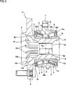
3 zeigt eine zu 1 äquivalente Ansicht, die ein drittes Beispiel der veranschaulichenden Ausführungsform der vorliegenden Erfindung darstellt. 3 shows one too 1 An equivalent view illustrating a third example of the illustrative embodiment of the present invention.
4 zeigt eine Schnittansicht, die ein Beispiel der herkömmlichen Struktur einer zweireihigen Wälzlagereinheit für eine Radhalterung darstellt. 4 FIG. 10 is a sectional view showing an example of the conventional structure of a double-row rolling bearing unit for a wheel mount. FIG.
5 zeigt eine Schnittansicht eines Innenrings einer axialen Innenseite, um die Probleme der herkömmlichen Struktur zu veranschaulichen. 5 shows a sectional view of an inner ring of an axial inside to illustrate the problems of the conventional structure.
Detaillierte BeschreibungDetailed description
[Erstes Beispiel der vorliegenden Ausführungsform]First Example of Present Embodiment
1 zeigt ein erstes Beispiel einer Ausführungsform der vorliegenden Erfindung. Eine zweireihige Wälzlagereinheit 1a für eine Radhalterung des ersten Beispiels wird zum drehbaren Halten eines nicht angetrieben Rades an einer Aufhängung (Achsschenkel) verwendet und weist einen Außenring 2, eine Nabenspindel 3a, ein Paar von Innenringen 4a, 4b und mehrere Wälzkörper 5, 5 auf. 1 shows a first example of an embodiment of the present invention. A double row rolling bearing unit 1a for a wheel holder of the first example is used for rotatably supporting a non-driven wheel on a suspension (steering knuckle) and has an outer ring 2 , a hub spindle 3a , a pair of inner rings 4a . 4b and several rolling elements 5 . 5 on.
Der Außenring 2 umfasst ein Paar von Außenring-Laufbahnen 6, 6, die an einem Innenumfang vorgesehen sind, und einen Kopplungsflansch 7, der an einem Außenumfang vorgesehen ist. Das Paar von Außenring-Laufbahnen 6, 6 weist eine konisch konkave Oberflächenform auf, die in einer Richtung geneigt ist, in der ein Durchmesser (Innendurchmesser) in einer Richtung, in der sie sich in Bezug auf eine axiale Richtung voneinander entfernen, zunimmt. Der Kopplungsflansch 7 koppelt und befestigt die zweireihige Wälzlagereinheit 1a für eine Radhalterung an der Aufhängung.The outer ring 2 includes a pair of outer ring raceways 6 . 6 provided on an inner circumference and a coupling flange 7 which is provided on an outer periphery. The pair of outer ring raceways 6 . 6 has a conical concave surface shape which is inclined in a direction in which a diameter (inner diameter) increases in a direction in which they move away from each other with respect to an axial direction. The coupling flange 7 couples and fastens the double row rolling bearing unit 1a for a wheel mount on the suspension.
Eine Nabenspindel 3a umfasst ein Pilotteil 8, einen Nabenflanschabschnitt 9, einen zylindrischen Oberflächenabschnitt 10, eine gestufte Fläche 11, ein Verstemmteil 12, einen konkaven Außenabschnitt 15, einen konkaven Innenabschnitt 16 und einen Trennwandabschnitt 17. Das Pilotteil 8 dient der äußeren Befestigung eines Rades und eines Drehelements zum Bremsen daran und der Positionierung des Rades und des Drehelements zum Bremsen, und ist an einem axialen Außenendabschnitt der Nabenspindel 3a vorgesehen. Der Nabenflansch 9 hält und fixiert das Rad und das Drehelement zum Bremsen daran und ist an einem Teil vorgesehen, der sich in der Nähe des axialen Außenendes eines Außenumfangs der Nabenspindel 3a befindet. Der zylindrische Oberflächenabschnitt 10 ist an einem axialen Mittelabschnitt des Außenumfangs der Nabenspindel 3a vorgesehen und weist eine einzige zylindrische Oberflächenform auf, deren Durchmesser sich mit Ausnahme beider axialer Endabschnitte (durchgehende Abschnitte der gestuften Fläche 11 und des Verstemmteils 12) axial nicht ändert. Die gestufte Fläche 11 ist gegenüber der axialen Innenseite zwischen der axialen Innenfläche des Nabenflansches 9 und des zylindrischen Oberflächenabschnitts 10 vorgesehen. Indes ist in dem Beispiel der 1 der Außendurchmesser der gestuften Fläche 11 im Wesentlichen gleich ausgebildet wie ein Außendurchmesser einer axialen Außenstirnfläche des Innenrings 4a der axialen Außenseite des Paares von Innenringen 4a, 4b. Wie in 2 gezeigt, die ein zweites Beispiel der veranschaulichten Ausführungsform (die später beschrieben wird) darstellt, kann jedoch der Außendurchmesser der gestuften Fläche 11 gleich wie der Außendurchmesser einer axialen Außenstirnfläche (eine Kontaktfläche mit dem Innenring 4b der axialen Innenseite) des Verstemmteils 12 ausgebildet sein. Das Verstemmteil 12 ist an einem axialen Innenendabschnitt der Nabenspindel 3a radial nach außen gebogen ausgebildet. Der konkave Außenabschnitt 15 ist an einem Mittelabschnitt der Nabenspindel 3a vorgesehen, wobei eine Öffnung nur in Richtung der axialen Außenstirnfläche der Nabenspindel 3a vorgesehen ist, und (mit Ausnahme des axialen Innenendabschnitts, der ein durchgehender Abschnitt einer Bodenfläche und eines Innenumfangs ist) ein Innendurchmesser D15 derselben ist über die axiale Richtung im Wesentlichen konstant (wird auch für einen notwendigen Zug zum Herausziehen aus einer Pressform angesehen, wobei der Innendurchmesser D15 einen Durchschnittswert angibt. Dies trifft auch auf den Innendurchmesser D16 des konkaven Innenabschnitts 16 zu). Indes sind der Innenumfang des konkaven Außenabschnitts 15 und der Innenumfang des Pilotteils 8 über einen geneigten Flächenabschnitt 18 durchgehend ausgebildet (eine konisch konkave Oberflächenform in dem gezeigten Beispiel), der in einer Richtung geneigt ist, in der ein Durchmesser (Innendurchmesser) in Richtung der axialen Außenseite zunimmt. Der konkave Innenabschnitt 16 ist an einem mittleren Abschnitt der Nabenspindel 3a vorgesehen, wobei eine Öffnung lediglich in Richtung der axialen Innenstirnfläche der Nabenspindel 3a vorgesehen ist, und (mit Ausnahme des axialen Außenendabschnitts, der ein durchgehender Abschnitt der Bodenfläche und eines Innenumfangs ist) ein Innendurchmesser D16 derselben ist über die axiale Richtung im Wesentlichen konstant. Ein Trennwandabschnitt 17 ist zwischen der Bodenfläche des konkaven Außenabschnitts 15 und der Bodenfläche des konkaven Innenabschnitts 16 vorgesehen.A hub spindle 3a includes a pilot part 8th , a hub flange portion 9 , a cylindrical surface section 10 , a stepped surface 11 , a Verstemmteil 12 , a concave outer section 15 , a concave interior section 16 and a partition wall section 17 , The pilot part 8th is used to externally attach a wheel and a rotary member for braking thereon and the positioning of the wheel and the rotary member for braking, and is at an axial outer end portion of the hub spindle 3a intended. The hub flange 9 holds and fixes the wheel and the rotary member thereon for braking and is provided on a part located near the axially outer end of an outer circumference of the hub spindle 3a located. The cylindrical surface section 10 is at an axial center portion of the outer circumference of the hub spindle 3a provided and has a single cylindrical surface shape whose diameter except for both axial end portions (continuous portions of the stepped surface 11 and the Verstemmteils 12 ) does not change axially. The stepped surface 11 is opposite to the axial inside between the axial inner surface of the hub flange 9 and the cylindrical surface portion 10 intended. However, in the example of the 1 the outer diameter of the stepped surface 11 formed substantially the same as an outer diameter of an axial outer end surface of the inner ring 4a the axial outside of the pair of inner rings 4a . 4b , As in 2 however, showing the second example of the illustrated embodiment (to be described later), the outer diameter of the stepped surface may be shown 11 same as the outer diameter of an axial outer end surface (a contact surface with the inner ring 4b the axial inside) of the caulking 12 be educated. The caulking part 12 is at an axial inner end portion of the hub spindle 3a formed bent radially outward. The concave outer section 15 is at a central portion of the hub spindle 3a provided, wherein an opening only in the direction of the axial outer end face of the hub spindle 3a is provided, and (with the exception of the axial inner end portion, which is a continuous portion of a bottom surface and an inner periphery) an inner diameter D 15 thereof is substantially constant over the axial direction (is also considered a necessary pull for pulling out of a mold, the inner diameter D 15 indicates an average value, which also applies to the inner diameter D 16 of the concave inner section 16 to). Meanwhile, the inner circumference of the concave outer portion 15 and the inner circumference of the pilot part 8th over an inclined surface section 18 formed continuously (a conical concave surface shape in the example shown), which is inclined in a direction in which a diameter (inner diameter) increases in the direction of the axial outside. The concave interior section 16 is at a middle section of the hub spindle 3a provided, wherein an opening only in the direction of the axial inner end face of the hub spindle 3a is provided, and (except for the axial outer end portion, which is a continuous portion of the bottom surface and an inner periphery), an inner diameter D 16 thereof is substantially constant over the axial direction. A partition wall section 17 is between the bottom surface of the concave outer section 15 and the bottom surface of the concave inner portion 16 intended.
Das Paar von Innenringen 4a, 4b weist einreihige Innenring-Laufbahnen 13a, 13b auf, die jeweils an Außenumfängen davon vorgesehen sind, und außen befestigt und an dem zylindrischen Oberflächenabschnitt 10 mittels Presspassung fixiert (eingepresst). Die Innenring-Laufbahn 13a des Innenrings 4a der axialen Außenseite und die Innenring-Laufbahn 13b des Innenrings 4b der axialen Innenseite weisen eine konisch konvexe Oberflächenform auf, die in einer Richtung geneigt ist, in der ein Durchmesser (Außendurchmesser) jeweils in einer Richtung, in der sie sich voneinander entfernen, zunimmt. Indes sind Abschnitte, die beide Endabschnitte der Innenring-Laufbahnen 13a, 13b bilden und Außenumfangskantenabschnitten der Wälzkörper 5, 5 entsprechen, jeweils mit konkaven Vertiefungsabschnitten 26a bis 26d, die radial nach innen vertieft sind, ausgebildet.The pair of inner rings 4a . 4b has single row inner ring raceways 13a . 13b on each of outer peripheries thereof provided and fixed externally and on the cylindrical surface portion 10 fixed by press fit (pressed in). The inner ring raceway 13a of the inner ring 4a the axial outside and the inner ring raceway 13b of the inner ring 4b the axial inside have a conical convex surface shape inclined in a direction in which a diameter (outer diameter) increases in each case in a direction in which they move away from each other. However, portions are both end portions of the inner ring raceways 13a . 13b form and outer peripheral edge portions of the rolling elements 5 . 5 correspond, each with concave recessed sections 26a to 26d , which are recessed radially inwardly formed.
Die Wälzkörper 5, 5 sind jeweils frei rollbar zwischen den Außenring-Laufbahnen 6, 6 und den Innenring-Laufbahnen 13a, 13b vorgesehen und werden durch Käfige 14, 14 gehalten. In dem ersten Beispiel ist jeder der Wälzkörper 5, 5 ein Keilrollenlager.The rolling elements 5 . 5 are each freely rollable between the outer ring raceways 6 . 6 and the inner ring raceways 13a . 13b provided and are by cages 14 . 14 held. In the first example, each of the rolling elements 5 . 5 a wedge roller bearing.
Insbesondere ist gemäß der zweireihigen Wälzlagereinheit 1a für eine Radhalterung des ersten Beispiels ein Teil mit einem im Wesentlichen konstanten Innendurchmesser D15 des konkaven Außenabschnitts 15 an einer Position vorgesehen, an der dieser radial mit der Innenring-Laufbahn 13a des Innenrings 4a der axialen Außenseite überlappt, und ein Teil mit einem im Wesentlichen konstanten Innendurchmesser D16 des konkaven Innenabschnitts 16 ist an einer Position vorgesehen, an der dieser mit der Innenring-Laufbahn 13b des Innenrings 4a der axialen Innenseite überlappt. Zudem sind der Innendurchmesser D15 des konkaven Außenabschnitts 15 und der Innendurchmesser D16 des konkaven Innenabschnitts 16 im Wesentlichen gleich ausgebildet (D15 ≒ D16). Die Bodenfläche (eine axiale Außenfläche des Trennwandabschnitts 17) des konkaven Außenabschnitts 15 ist an einer Position vorgesehen, an der diese nicht mit der Innenring-Laufbahn 13a des Innenrings 4a der axialen Außenseite überlappt, das heißt, an einer Position zwischen einer axialen Innenstirnfläche des Innenrings 4a der axialen Außenseite und einer axialen Innenstirnkante der Innenring-Laufbahn 13a mit Bezug auf die Axialrichtung. Zudem ist die Bodenfläche (eine axiale Innenstirnfläche des Trennwandabschnitts 17) des konkaven Innenabschnitts 16 an einer Position vorgesehen, an der diese nicht mit der Innenring-Laufbahn 13b des Innenrings 4b der axialen Innenseite überlappt, das heißt, an einer Position zwischen einer axialen Außenstirnfläche des Innenrings 4b der axialen Innenseite und einer axialen Außenstirnkante der Innenring-Laufbahn 13b mit Bezug auf die Axialrichtung. Ein axialer Abstand 115 von einer virtuellen Ebene α, die einen Kontaktabschnitt zwischen der axialen Innenstirnfläche des Innenrings 4a der axialen Außenseite und der axialen Außenstirnfläche des Innenrings 4b der axialen Innenseite umfasst, zu der Bodenfläche des konkaven Außenabschnitts 15 ist gleich wie ein axialer Abstand L16 von der virtuellen Ebene α zu der Bodenfläche des konkaven Innenabschnitts 16 ausgebildet (L15 = L16). Das heißt, die Formen der Teile, die radial mit wenigstens den Innenring-Laufbahnen 13a, 13b überlappen, des konkaven Außenabschnitts 15 und des konkaven Innenabschnitts 16 sind mit Bezug auf die virtuelle Ebene α symmetrisch ausgebildet. Darüberhinaus ist eine Öffnung (ein durchgehender Abschnitt des Innenumfangs des konkaven Außenabschnitts 15 und des geneigten Flächenabschnitts 18) des konkaven Außenabschnitts 15 an einer axial weiter außen liegenden Seite angeordnet als die axiale Außenstirnfläche des Innenrings 4a der axialen Außenseite. Zudem ist ein axialer Innenendabschnitt des konkaven Vertiefungsabschnitts 26b, der an dem axialen Innenendabschnitt der Innenring-Laufbahn 13a des Innenrings 4a der axialen Außenseite vorgesehen ist, an einer axial weiter außen liegenden Seite als der durchgehende Abschnitt des Innenumfangs und der Bodenfläche des konkaven Außenabschnitts 15 angeordnet, und ein axialer Außenendabschnitt des konkaven Vertiefungsabschnitts 26c, der an dem axialen Außenendabschnitt der Innenringbahn 13b des Innenrings 4b der axialen Innenseite vorgesehen ist, ist an einer axial weiter innen liegenden Seite als der durchgehende Abschnitt des Innenumfangs und der Bodenfläche des konkaven Innenabschnitts 16 angeordnet. Darüberhinaus ist ein axialer Außenendabschnitt des konkaven Vertiefungsabschnitts 26d, der an dem axialen Innenendabschnitt der Innenring-Laufbahn 13b des Innenrings 4b der axialen Innenseite vorgesehen ist, an einer axial weiter außen liegenden Seite als die Öffnung des konkaven Innenabschnitts 16 angeordnet.In particular, according to the double-row rolling bearing unit 1a for a wheel mount of the first example, a part having a substantially constant inner diameter D 15 of the concave outer portion 15 provided at a position at which this radially with the inner ring raceway 13a of the inner ring 4a overlaps the axial outside, and a part having a substantially constant inner diameter D 16 of the concave inner portion 16 is provided at a position where this with the inner ring raceway 13b of the inner ring 4a overlaps the axial inside. In addition, the inner diameter D 15 of the concave outer portion 15 and the inner diameter D 16 of the concave inner portion 16 essentially the same design (D15 ≒ D16). The bottom surface (an axial outer surface of the partition wall portion 17 ) of the concave outer portion 15 is provided at a position where it does not interfere with the inner ring raceway 13a of the inner ring 4a the axial outside overlaps, that is, at a position between an axial inner end face of the inner ring 4a the axial outside and an axial inner end edge of the inner ring raceway 13a with respect to the axial direction. In addition, the bottom surface (an axial inner end surface of the partition wall portion 17 ) of the concave inner portion 16 provided at a position where this is not with the inner ring raceway 13b of the inner ring 4b overlaps the axial inside, that is, at a position between an axial outer end surface of the inner ring 4b the axial inside and an axial outer end edge of the inner ring raceway 13b with respect to the axial direction. An axial distance 115 from a virtual plane α, which has a contact portion between the axially inner end face of the inner ring 4a the axial outside and the axial outer end face of the inner ring 4b the axial inside, to the bottom surface of the concave outer portion 15 is equal to an axial distance L 16 from the virtual plane α to the bottom surface of the concave inner portion 16 formed (L 15 = L 16 ). That is, the shapes of the parts radially with at least the inner ring raceways 13a . 13b overlap the concave outer section 15 and the concave inner section 16 are formed symmetrically with respect to the virtual plane α. In addition, an opening (a continuous portion of the inner periphery of the concave outer portion 15 and the inclined surface portion 18 ) of the concave outer portion 15 arranged on an axially further outward side than the axial outer end surface of the inner ring 4a the axial outside. In addition, an axial inner end portion of the concave recess portion 26b at the axial inner end portion of the inner ring raceway 13a of the inner ring 4a is provided on the axially outer side, on an axially outer side than the continuous portion of the inner periphery and the bottom surface of the concave outer portion 15 disposed, and an axial outer end portion of the concave recess portion 26c at the axial outer end portion of the inner raceway 13b of the inner ring 4b is provided on the axially inner side, is on an axially further inner side than the continuous portion of the inner periphery and the bottom surface of the concave inner portion 16 arranged. In addition, an axial outer end portion of the concave recess portion 26d at the axial inner end portion of the inner ring raceway 13b of the inner ring 4b is provided on the axially inner side, on an axially outer side than the opening of the concave inner portion 16 arranged.
Indes ist ein Dichtungsring 19 zwischen dem Innenumfang des axialen Außenendabschnitts des Außenrings 2 und dem Außenumfang des axialen Außenendabschnitts (Endabschnitt auf der Seite mit dem großen Durchmesser) des Innenrings 4a der axialen Außenseite vorgesehen, und eine mit einem Boden versehene zylindrische Abdeckung 20 ist an dem axialen Innenendabschnitt des Außenrings 2 befestigt (innen angebracht und befestigt). Dabei werden beide axialen Endöffnungen eines Raums 21, in dem die Wälzkörper 5, 5 befestigt sind, verschlossen, so dass verhindert wird, dass Schmiermittel, das sich in dem Raum 21 befindet, nach außen abgegeben wird, und so dass verhindert wird, dass Fremdstoffe, die in einem äußeren Raum vorhanden sind, in den Raum 21 eingebracht werden. Ferner ist ein Codierer 22 außen angebracht und an dem axialen Innenendabschnitt (Innenendabschnitt auf der Seite mit dem großen Durchmesser) des Innenrings 4b der axialen Innenseite befestigt. Eine Erfassungseinheit eines (nicht dargestellt) Sensors ist gegenüber einer zu erfassenden Oberfläche des Codierers 22 über die Abdeckung 20 angeordnet, so dass es möglich ist, eine Drehzahl der Nabenspindel 3a zu erfassen.However, there is a sealing ring 19 between the inner periphery of the axial outer end portion of the outer ring 2 and the outer periphery of the axial outer end portion (large-diameter-side end portion) of the inner ring 4a the axial outside provided, and a bottomed cylindrical cover 20 is at the axial inner end portion of the outer ring 2 attached (attached and attached inside). In this case, both axial end openings of a room 21 in which the rolling elements 5 . 5 are fastened, closed, so that prevents lubricant that is in the room 21 is discharged to the outside, and so that foreign matter, which is present in an external space, is prevented from entering the room 21 be introduced. Further, an encoder 22 attached externally and on the axial Inner end portion (inner end portion on the large-diameter side) of the inner ring 4b attached to the axial inside. A detection unit of a sensor (not shown) is opposite to a surface of the encoder to be detected 22 over the cover 20 arranged so that it is possible to have a speed of the hub spindle 3a capture.
Beim Zusammenbau der zweireihigen Wälzlagereinheit 1a für eine Radhalterung des ersten Beispiels wird ein zweireihiges Keilrollenlager, in dem die Wälzkörper 5, 5, die Käfige 14, 14 und das Innenringpaar 4a, 4b an der radialen Innenseite des Außenrings 2 angeordnet und verbunden sind, in den zylindrischen Flächenabschnitt 10 eingepresst, so dass die Stirnflächen des Innenringpaars 4a, 4b auf der Seite des kleinen Durchmessers aneinander stoßen, so dass die axiale Außenstirnfläche des Innenrings 4a der axialen Außenseite in Kontakt mit der gestuften Fläche 11 ist (an diese anstößt). Dann wird ein Teil, der axial weiter nach innen vorsteht als die axiale Innenstirnfläche des Innenrings 4b der axialen Innenseite, des axialen Innenendabschnitts der Nabenspindel 3a radial nach außen verformt, um den Verstemmteil 12 zu bilden, und das Paar der Innenringe 4a, 4b wird durch das Verstemmteil 12 axial nach außen in Richtung der gestuften Fläche 11 gedrückt. Dabei wird eine Kraft auf das Innenringpaar 4a, 4b in einer Richtung, in der sie sich annähern, ausgeübt, so dass die Wälzkörper 5, 5 mit einem Rücken-an-Rücken-Anordnungskontaktwinkel ausgebildet werden. Zu diesem Zeitpunkt können nach der Presspassung des Innenrings 4a der axialen Außenseite in den zylindrischen Flächenabschnitt 10 die Wälzkörper 5, 5, die Käfige 14, 14 und der Außenring 2 konzentrisch mit der Nabenspindel 3a um die Nabenspindel 3a angeordnet werden, und anschließend kann der Innenring 4b der axialen Innenseite in den zylindrischen Flächenabschnitt 10 eingepresst werden.When assembling the double row rolling bearing unit 1a for a wheel support of the first example is a double row roller bearing, in which the rolling elements 5 . 5 , the cages 14 . 14 and the inner ring pair 4a . 4b on the radial inside of the outer ring 2 are arranged and connected in the cylindrical surface portion 10 pressed in, so that the end faces of the inner ring pair 4a . 4b on the side of the small diameter abut each other, so that the axial outer end face of the inner ring 4a the axial outside in contact with the stepped surface 11 is (at these abuts). Then, a part projecting axially further inward than the axial inner end surface of the inner ring 4b the axial inside, the axial inner end portion of the hub spindle 3a deformed radially outward to the Verstemmteil 12 to form, and the pair of inner rings 4a . 4b gets through the caulking part 12 axially outward in the direction of the stepped surface 11 pressed. This is a force on the inner ring pair 4a . 4b in a direction in which they approach, exercised, so that the rolling elements 5 . 5 be formed with a back-to-back arrangement contact angle. At this time, after the press-fitting of the inner ring 4a the axial outside in the cylindrical surface portion 10 the rolling elements 5 . 5 , the cages 14 . 14 and the outer ring 2 concentric with the hub spindle 3a around the hub spindle 3a can be arranged, and then the inner ring 4b the axial inside in the cylindrical surface portion 10 be pressed.
Gemäß der zweireihigen Wälzlagereinheit 1a für eine Radhalterung des zuvor beschriebenen ersten Beispiels ist es möglich, die Verformung des Paars von Innenringen 4a, 4b, die beim Zusammenbau der zweireihigen Wälzlagereinheit 1a für eine Radhalterung entsteht, weitgehend zu unterdrücken und die Verformunggrade zwischen dem Paar von Innenringen 4a, 4b im Wesentlichen gleich auszubilden.According to the double row rolling bearing unit 1a for a wheel support of the first example described above, it is possible to prevent the deformation of the pair of inner rings 4a . 4b involved in assembling the double row rolling bearing unit 1a for a wheel mount arises, largely suppressing and the degrees of deformation between the pair of inner rings 4a . 4b essentially the same.
Das heißt, dass der konkave Außenabschnitt 15 gemäß dem ersten Beispiel an dem mittleren Abschnitt der Nabenspindel 3a vorgesehen ist, wobei eine Öffnung lediglich in Richtung der axialen Außenstirnfläche der Nabenspindel 3a vorgesehen ist und die Bodenfläche des konkaven Außenabschnitts 15 an der Position vorgesehen ist, an der diese nicht radial mit der Innenring-Laufbahn 13a des Innenrings 4a der axialen Außenseite überlappt. Darüberhinaus ist der konkave Innenabschnitt 16 an dem mittleren Abschnitt der Nabenspindel 3a vorgesehen, wobei die Öffnung lediglich in Richtung der axialen Innenstirnfläche der Nabenspindel 3a vorgesehen ist, und die Bodenfläche des konkaven Innenabschnitts 16 ist an der Position vorgesehen, an der diese sich nicht radial mit der Innenring-Laufbahn 13b des Innenrings 4b der axialen Innenseite überlappt. Der Innendurchmesser D15 des konkaven Außenabschnitts 15 und der Innendurchmesser D16 des konkaven Innenabschnitts 16 sind gleich. Dadurch wird ein Teil der Nabenspindel 3a, der an der radialen Innenseite der Innenring-Laufbahn 13a des Innenrings 4a der axialen Außenseite angeordnet ist, und der Teil der Nabenspindel, der an der radialen Innenseite der Innenring-Laufbahn 13b des Innenrings 4b der axialen Innenseite angeordnet ist, derart ausgebildet, dass sie eine Hohlform mit dem gleichem Durchmesser aufweisen, so dass die radialen Steifigkeiten beider Teile gering gehalten werden. Ferner wird in dem ersten Beispiel der axiale Abstand L15 der Bodenfläche des konkaven Außenabschnitts 15 von der virtuellen Ebene α, die den Kontaktabschnitt zwischen der axialen Innenstirnfläche des Innenrings 4a der axialen Außenseite und der axialen Außenstirnfläche des Innenrings 4b der axialen Innenseite umfasst, gleich wie der axiale Abstand 116 der Bodenfläche des konkaven Innenabschnitts 16 von der virtuellen Ebene α ausgebildet (L15 = L16). Werden somit das Paar von Innenringen 4a, 4b in den zylindrischen Flächenabschnitt 10 eingepresst, ist es möglich, die radialen Verformungsgrade des Paar von Innenringen 4a, 4b weitgehend zu unterdrücken und die Verformungsgrade zwischen dem Innenring 4a der axialen Außenseite und dem Innenring 4b der axialen Innenseite im Wesentlichen gleich auszubilden. Beispielsweise ist es möglich, einen Einfluss der Verformungen des Paars von Innenringen 4a, 4b in einer Richtung zu verringern, in der der Neigungswinkel der Innenring-Laufbahn 13a, 13b abnimmt, wenn das Paar von Innenringen 4a, 4b in den zylindrischen Oberflächenabschnitt 10 eingepresst wird.That is, the concave outer section 15 according to the first example at the central portion of the hub spindle 3a is provided, wherein an opening only in the direction of the axial outer end face of the hub spindle 3a is provided and the bottom surface of the concave outer portion 15 is provided at the position where they are not radially with the inner raceway 13a of the inner ring 4a overlaps the axial outside. In addition, the concave interior section 16 at the central portion of the hub spindle 3a provided, wherein the opening only in the direction of the axial inner end face of the hub spindle 3a is provided, and the bottom surface of the concave inner portion 16 is provided at the position where it is not radially with the inner ring raceway 13b of the inner ring 4b overlaps the axial inside. The inner diameter D 15 of the concave outer portion 15 and the inner diameter D 16 of the concave inner portion 16 are equal. This will become part of the hub spindle 3a at the radial inner side of the inner ring raceway 13a of the inner ring 4a the axial outer side is arranged, and the part of the hub spindle, on the radially inner side of the inner ring raceway 13b of the inner ring 4b is arranged on the axial inside, formed such that they have a hollow shape with the same diameter, so that the radial stiffnesses of both parts are kept small. Further, in the first example, the axial distance L 15 becomes the bottom surface of the concave outer portion 15 from the virtual plane α, which is the contact portion between the axially inner end face of the inner ring 4a the axial outside and the axial outer end face of the inner ring 4b the axial inside includes, same as the axial distance 116 the bottom surface of the concave inner portion 16 formed by the virtual plane α (L 15 = L 16 ). So become the pair of inner rings 4a . 4b in the cylindrical surface section 10 Pressed, it is possible the radial degrees of deformation of the pair of inner rings 4a . 4b largely suppress and the degrees of deformation between the inner ring 4a the axial outside and the inner ring 4b form the axial inside substantially the same. For example, it is possible to influence the deformations of the pair of inner rings 4a . 4b decreasing in one direction, in which the inclination angle of the inner ring raceway 13a . 13b decreases when the pair of inner rings 4a . 4b in the cylindrical surface section 10 is pressed.
Ferner ist die Öffnung des konkaven Außenabschnitts 15 an einer axial weiter außen liegenden Seite angeordnet als die axiale Außenstirnfläche des Innenrings 4a der axialen Außenseite. Dabei werden ein Teil der Nabenspindel 3a, die an der radialen Innenseite des Teils angeordnet ist, der sich in der Nähe des axialen Außenendes (mit Ausnahme des axialen Innenendabschnitts) des Innenrings 4a der axialen Außenseite befindet, und ein Teil der Nabenspindel 3a, der an der radialen Innenseite des Teils angeordnet ist, der sich in der Nähe des axialen Innenendes (mit Ausnahme des axialen Außenendabschnitts) des Innenrings 4b der axialen Innenseite befindet, derart ausgebildet, dass sie eine Hohlform mit einem im Wesentlichen gleichen Durchmesser aufweisen, so dass die radialen Steifigkeiten beider Teile im Wesentlichen gleich sind. Dadurch wird eine starke Reaktionskraft auf die Kraft, mit der das Paar von Innenringen 4a, 4b axial nach außen in Richtung der gestuften Fläche 11 durch das Verstemmteil 12 gedrückt wird, auf den Teil ausgeübt, der sich in der Nähe des Innendurchmessers der axialen Außenstirnfläche des Innenrings 4a der axialen Außenseite befindet. Folglich kann eine Spannungsverteilung, die durch das Pressen des Paares der Innenringe 4a, 4b axial nach außen in Richtung der gestuften Fläche 11 durch das Verstemmteil 12 erfolgt, zwischen dem axialen Außenendabschnitt des Innenrings 4a der axialen Außenseite und dem axialen Innenendabschnitt des Innenrings 4b der axialen Innenseite im Wesentlichen gleich ausgebildet werden. Indes ist in dem Beispiel der 1, wie zuvor beschrieben, der Außendurchmesser der gestuften Fläche 11 im Wesentlichen gleich dem Außendurchmesser der axialen Außenstirnfläche des Innenrings 4a der axialen Außenseite. Wird jedoch, gleich wie in einem zweiten Beispiel der 2 (das später beschrieben wird), der Außendurchmesser der gestuften Fläche 11 gleich wie der Außendurchmesser der axialen Innenstirnfläche des Verstemmteils 12 ausgebildet, kann die Spannungsverteilung zwischen dem axialen Außenendabschnitt des Innenrings 4a der axialen Außenseite und dem axialen Innenendabschnitt des Innenrings 4b der axialen Innenseite näher an diesen ausgebildet werden, so dass es möglich ist, den Unterschied zwischen den Verformungsgraden zwischen dem Innenring 4a der axialen Außenseite und dem Innenring 4b der axialen Innenseite weiter zu verringern.Further, the opening of the concave outer portion 15 arranged on an axially further outward side than the axial outer end surface of the inner ring 4a the axial outside. This will be part of the hub spindle 3a disposed on the radially inner side of the part, located near the axial outer end (excluding the axial inner end portion) of the inner ring 4a the axial outside, and a part of the hub spindle 3a which is disposed on the radially inner side of the part, which is in the vicinity of the axial inner end (with the exception of the axial outer end portion) of the inner ring 4b the axial inner side is formed so as to have a hollow shape with a substantially same diameter, so that the radial stiffnesses of both parts are substantially equal. This will give a strong reaction force to the force with which the pair of inner rings 4a . 4b axially outward in the direction of the stepped surface 11 through the caulking part 12 is pressed on the part which is located near the inner diameter of the axial outer end surface of the inner ring 4a the axial outside is located. Consequently, a stress distribution obtained by pressing the pair of inner rings 4a . 4b axially outward in the direction of the stepped surface 11 through the caulking part 12 takes place between the axial outer end portion of the inner ring 4a the axial outside and the axially inside end portion of the inner ring 4b the axial inside are formed substantially the same. However, in the example of the 1 As previously described, the outer diameter of the stepped surface 11 substantially equal to the outer diameter of the axial outer end surface of the inner ring 4a the axial outside. However, the same as in a second example the 2 (which will be described later), the outer diameter of the stepped surface 11 same as the outer diameter of the axially inner end face of the Verstemmteils 12 formed, the stress distribution between the axial outer end portion of the inner ring 4a the axial outside and the axially inside end portion of the inner ring 4b be formed closer to the axial inner side, so that it is possible, the difference between the degrees of deformation between the inner ring 4a the axial outside and the inner ring 4b to further reduce the axial inside.
Ferner ist es gemäß der zweireihigen Wälzlagereinheit 1a für eine Radhalterung des ersten Beispiels, wie zuvor beschrieben, möglich, in einem Zustand, in dem das Paar von Innenringen 4a, 4b in dem zylindrischen Oberflächenabschnitt 10 der Nabenspindel 3a eingepresst wird und in dem das Paar von Innenringen 4a, 4b durch das Verstemmteil 12 axial nach außen in Richtung der gestuften Fläche 11 gedrückt wird, die Verformungsgrade des Paar von Innenringen 4a, 4b weitgehend zu unterdrücken und die Verformungsgrade zwischen dem Paar von Innenringen 4a, 4b im Wesentlichen gleich auszubilden. Somit ist es möglich, das gleiche Bauteil als Innenringpaar 4a, 4b (Teilen des Bauteils) zu verwenden, um das Bauteil auf einfache Weise zu steuern und die Herstellungskosten der zweireihigen Wälzlagereinheit 1a für eine Radhalterung zu verringern.Further, it is according to the double-row rolling bearing unit 1a for a wheel holder of the first example, as described above, possible in a state where the pair of inner rings 4a . 4b in the cylindrical surface portion 10 the hub spindle 3a is pressed and in which the pair of inner rings 4a . 4b through the caulking part 12 axially outward in the direction of the stepped surface 11 is pressed, the degrees of deformation of the pair of inner rings 4a . 4b largely suppress and the degrees of deformation between the pair of inner rings 4a . 4b essentially the same. Thus it is possible to use the same component as inner ring pair 4a . 4b (Parts of the component) to use to control the component in a simple manner and the manufacturing cost of the double row rolling bearing unit 1a for a wheel mount.
[Zweites Beispiel der veranschaulichenden Ausführungsform]Second Example of Illustrative Embodiment
2 zeigt ein zweites Beispiel der vorliegenden Ausführungsform der vorliegenden Erfindung. In einer Nabenspindel 3b, die eine zweireihige Wälzlagereinheit 1b für eine Radhalterung gemäß dem zweiten Beispiel bildet, sind der Außendurchmesser der gestuften Fläche 11 zum Aufliegen der axialen Außenstirnfläche des Innenrings 4a der axialen Außenseite im Wesentlichen gleich dem Außendurchmesser der axialen Innenstirnfläche (eine Kontaktfläche mit dem Innenring 4b der axialen Innenseite) des Verstemmteils 12 ausgebildet. Ferner ist eine Öffnung (ein durchgehender Abschnitt zwischen dem Innenumfang eines konkaven Außenabschnitts 15a und eines geneigten Flächenabschnitts 18a, der an einem Teil neben der axialen Außenseite des konkaven Außenabschnitts 15a vorgesehen ist) des konkaven Außenabschnitts 15a an einer axial weiter innen liegenden Seite (ein Abschnitt, an dem dieser nicht radial mit der Innenring-Laufbahn 13a des Innenrings 4a der axialen Außenseite überlappt) als die axiale Außenstirnfläche des Innenrings 4a der axialen Außenseite angeordnet. Insbesondere wird ein axialer Abstand S15a der Öffnung des konkaven Außenabschnitts 15a von der virtuellen Ebene α, die einen Kontaktabschnitt zwischen der axialen Innenstirnfläche des Innenrings 4a der axialen Außenseite und der axialen Außenstirnfläche des Innenrings 4b der axialen Innenseite umfasst, gleich wie ein axialer Abstand Sie der Öffnung des konkaven Innenabschnitts 16 von der virtuellen Ebene α ausgebildet (S15a = S16). Der Innenumfang des Pilotteils 8, das an einem axialen Außenendabschnitt der Nabenspindel 3a vorgesehen ist, und der Innenumfang des konkaven Außenabschnitts 15a sind durch den geneigten Flächenabschnitt 18a (eine konisch konkave Oberflächenform in dem gezeigten Beispiel), der in einer Richtung geneigt ist, in der ein Durchmesser (Innendurchmesser) in Richtung der axialen Außenseite zunimmt) durchgehend ausgebildet. Ein Teil des geneigten Flächenabschnitts 18a, an dem der axiale Abstand von der virtuellen Ebene α gleich einem axialen Abstand zwischen der virtuellen Ebene α und dem Verstemmteil 12 ist, ist mit einem konvexen Abschnitt 23, der radial über einen gesamten Umfang nach innen vorsteht, ausgebildet. In dem zweiten Beispiel ist der Innendurchmesser des konvexen Abschnitts 23 im Wesentlichen gleich einem Innenabschnitt des Verstemmteils 12 ausgebildet, und eine Form des Innenumfangs des konvexen Abschnitts 23 ist im Wesentlichen gleich einer Form eines Innenumfangs des Verstemmteils 12 ausgebildet. Ferner sind Verstärkungsrippen 24, 24, die in einer Umfangsrichtung eine im Wesentlichen dreieckige Form ausweisen, an mehreren in Umfangsrichtung gleich beabstandeten Positionen des geneigten Flächenabschnitts 18a vorgesehen. 2 shows a second example of the present embodiment of the present invention. In a hub spindle 3b , which is a double row rolling bearing unit 1b for a wheel holder according to the second example, the outer diameter of the stepped surface 11 for resting the axial outer end face of the inner ring 4a the axial outside substantially equal to the outer diameter of the axial inner end face (a contact surface with the inner ring 4b the axial inside) of the caulking 12 educated. Further, an opening (a continuous portion between the inner circumference of a concave outer portion 15a and an inclined surface portion 18a at a portion adjacent to the axial outside of the concave outer portion 15a is provided) of the concave outer portion 15a on an axially inner side (a portion where it is not radially with the inner ring raceway 13a of the inner ring 4a the axial outside overlaps) as the axial outer end surface of the inner ring 4a arranged the axial outside. In particular, an axial distance S 15a of the opening of the concave outer portion 15a from the virtual plane α, which has a contact portion between the axially inner end face of the inner ring 4a the axial outside and the axial outer end face of the inner ring 4b the axial inner side includes, like an axial distance of the opening of the concave inner portion 16 formed from the virtual plane α (S 15a = S16). The inner circumference of the pilot part 8th at an axial outer end portion of the hub spindle 3a is provided, and the inner circumference of the concave outer portion 15a are through the inclined surface section 18a (a conical concave surface shape in the shown example), which is inclined in a direction in which a diameter (inner diameter) increases in the direction of the axial outside) is continuously formed. Part of the inclined surface section 18a in which the axial distance from the virtual plane α equals an axial distance between the virtual plane α and the caulking part 12 is, is with a convex section 23 formed radially inwardly over an entire circumference, formed. In the second example, the inner diameter of the convex portion 23 substantially equal to an interior portion of the caulking member 12 formed, and a shape of the inner periphery of the convex portion 23 is substantially equal to a shape of an inner periphery of the Verstemmteils 12 educated. Further, reinforcing ribs 24 . 24 having a substantially triangular shape in a circumferential direction at a plurality of circumferentially equally spaced positions of the inclined surface portion 18a intended.
Gemäß dem zweiten Beispiel sind, wie zuvor beschrieben, die Innenring-Laufbahn 13a des Innenrings 4a der axialen Außenseite und der Teil des Innenumfangs des konkaven Außenabschnitts 15a, an dem der Innendurchmesser im Wesentlichen konstant ist, derart ausgebildet, dass sie radial überlappen, und die Innenring-Laufbahn 13b des Innenrings 4b der axialen Innenseite und der Teil des Innenumfangs des konkaven Innenabschnitts 16, an dem der Innendurchmesser im Wesentlichen konstant ist, sind derart ausgebildet, dass sie radial überlappen. Ferner sind die Form des Innenumfangs des konvexen Abschnitts 23 und die Form des Innenumfangs des Verstemmteils 12 im Wesentlichen gleich ausgebildet. Somit können die Formen der Teile der Nabenspindel 3b, die axiale Teile zwischen dem Verstemmteil 12 und dem konvex Abschnitt 23 bilden, das heißt, ein Teil, der an der radialen Innenseite des Innenrings 4a der axialen Außenseite angeordnet ist, und ein Teil, der an der radialen innenseite des Innenrings 4b der radialen Innenseite angeordnet ist, aufgrund der Symmetrie in Bezug auf die virtuelle Ebene α, verglichen mit dem ersten Beispiel der vorliegenden Ausführungsform, näher aneinander ausgebildet werden. Folglich ist es möglich, die Verformung des Innenrings 4a der axialen Außenseite näher an der Verformung des Innenrings 4b der axialen Innenseite auszubilden, wobei die Verformungen beim Zusammenbau der zweireihigen Wälzlagereinheit 1b für eine Radhalterung entstehen.According to the second example, as described above, the inner ring raceway 13a of the inner ring 4a the axial outside and the part of the inner periphery of the concave outer portion 15a in which the inner diameter is substantially constant, formed to overlap radially, and the inner ring raceway 13b of the inner ring 4b the axial inside and the part of the inner periphery of the concave inner portion 16 where the inner diameter is substantially constant formed so that they overlap radially. Further, the shape of the inner circumference of the convex portion 23 and the shape of the inner periphery of the caulking member 12 formed substantially the same. Thus, the shapes of the parts of the hub spindle 3b , the axial parts between the Verstemmteil 12 and the convex section 23 form, that is, a part which is at the radial inner side of the inner ring 4a the axial outer side is arranged, and a part which is on the radially inner side of the inner ring 4b of the radially inner side is formed closer to each other due to the symmetry with respect to the virtual plane α as compared with the first example of the present embodiment. Consequently, it is possible the deformation of the inner ring 4a the axial outside closer to the deformation of the inner ring 4b form the axial inside, wherein the deformations during assembly of the double row rolling bearing unit 1b for a bike mount arise.
Da indes die Öffnung des konkaven Außenabschnitts 15a an der axial weiter innen gelegenen Seite als die axiale Außenstirnfläche des Innenrings 4a der axialen Außenseite angeordnet ist, ist eine Dicke des Teils der Nabenspindel 3b, die an der radialen Innenseite des Nabenflanschabschnitts 9 angeordnet ist, verglichen mit dem ersten Beispiel der vorliegenden Ausführungsform, geringer. Somit sind in dem zweiten Beispiel die Verstärkungsrippen 24, 24 an den Umfangspositionen des geneigten Flächenabschnitts 18a vorgesehen, so dass die auf den Nabenflanschabschnitt 9 ausgeübte Last durch die Verstärkungsrippen 24, 24 gestützt werden kann.Since, however, the opening of the concave outer portion 15a on the axially inner side than the axial outer end surface of the inner ring 4a the axial outside is arranged, is a thickness of the part of the hub spindle 3b at the radial inside of the hub flange section 9 is smaller as compared with the first example of the present embodiment. Thus, in the second example, the reinforcing ribs 24 . 24 at the circumferential positions of the inclined surface portion 18a provided so that the on the hub flange section 9 applied load through the reinforcing ribs 24 . 24 can be supported.
Ferner sind in dem zweiten Beispiel die Vorsprungsgrößen der Verstärkungsrippen 24, 24 von dem geneigten Flächenabschnitt 18a größer als die Vorsprungsgröße des konvexen Abschnitts 23 ausgebildet. Solange jedoch die Last, die auf den Nabenflanschabschnitt 9 wirkt, unterstützt werden kann, können die Vorsprungsgrößen der Verstärkungsrippen 24, 24 im Wesentlichen gleich wie die Vorsprungsgröße des konvexen Abschnitts 23 ausgebildet werden, so dass die Teile der Nabenspindel 3b, die an der radialen Innenseite des Innenrings 4a der axialen Außenseite angeordnet und die an der radialen Innenseite des Innenrings 4b der axialen Innenseite angeordnet sind, hinsichtlich ihrer Formen näher aneinander ausgebildet werden. Die Konfigurationen und die Bedienung der anderen Teile entsprechen jenen des ersten Beispiels der vorliegenden Ausführungsform.Further, in the second example, the protrusion sizes of the reinforcing ribs 24 . 24 from the inclined surface portion 18a larger than the protrusion size of the convex portion 23 educated. However, as long as the load on the hub flange section 9 can be supported, the protrusion sizes of the reinforcing ribs 24 . 24 substantially the same as the protrusion size of the convex portion 23 be formed so that the parts of the hub spindle 3b at the radial inside of the inner ring 4a arranged on the axial outside and on the radially inner side of the inner ring 4b the axial inner side are arranged to be formed closer to each other in terms of their shapes. The configurations and the operation of the other parts are the same as those of the first example of the present embodiment.
[Drittes Beispiel der vorliegenden Ausführungsform]Third Example of the Present Embodiment
3 zeigt ein drittes Beispiel der vorliegenden Ausführungsform der vorliegenden Erfindung. Ein mittlerer Abschnitt der Nabenspindel 3c, die eine zweireihige Wälzlagereinheit 1c für eine Radhalterung des dritten Beispiels bildet, ist mit einem Eingriffsloch 25 zum Eingriff in eine Antriebswelle ausgebildet, um ein Drehmoment zu übertragen. In dem dritten Beispiel ist das Eingriffsloch 25 als ein Keilloch ausgebildet. Ein axialer Abstand Sout von der virtuellen Ebene α, die den Kontaktabschnitt zwischen der axialen Innenstirnfläche des Innenrings 4a der axialen Außenseite und der axialen Außenstirnfläche des Innenrings 4b der axialen Innenseite umfasst, zu einer axialen Außenstirnkante des Eingriffslochs 25 ist gleich ausgebildet wie ein axialer Abstand Sin von der virtuellen Ebene α zu der axialen Innenstirnkante des Eingriffslochs 25 (Sout = Sin). Der Innenumfang des Pilotteils 8, der an einem axialen Außenendabschnitt der Nabenspindel 3c ausgebildet ist, und eine axiale Außenstirnkante des Eingriffslochs 25 sind durch einen geneigten Oberflächenabschnitt 18b (eine konisch konkave Oberflächenform in dem gezeigten Beispiel), der in einer Richtung geneigt ist, in der ein Durchmesser (Innendurchmesser) in Richtung der axialen Außenseite zunimmt, durchgehend ausgebildet. Ein Teil, an dem der axiale Abstand von der virtuellen Ebene α gleich dem axialen Abstand zwischen der virtuellen Ebene α und dem Verstemmteil 12 ist, des geneigten Oberflächenabschnitts 18b ist mit einem konvexen Abschnitt 23a ausgebildet, der über einen gesamten Umfang radial nach innen vorsteht. Somit ist eine Form eines axialen Teils der Nabenspindel 3c zwischen dem Verstemmteil 12 und dem konvexen Abschnitt 23a im Wesentlichen symmetrisch in Hinblick auf die virtuelle Ebene α. Zudem sind die Verstärkungsrippen 24, 24, die aus Sicht einer Umfangsrichtung im Wesentlichen dreieckig ausgebildet ist, an mehreren in Umfangsrichtung gleich beabstandeten Positionen des geneigten Oberflächenabschnitts 18b ausgebildet. 3 shows a third example of the present embodiment of the present invention. A middle section of the hub spindle 3c , which is a double row rolling bearing unit 1c for a wheel holder of the third example is with an engagement hole 25 adapted to engage in a drive shaft to transmit a torque. In the third example, the engagement hole 25 formed as a wedge hole. An axial distance S out from the virtual plane α, which is the contact portion between the axial inner end face of the inner ring 4a the axial outside and the axial outer end face of the inner ring 4b the axial inner side, to an axial outer end edge of the engaging hole 25 is formed the same as an axial distance S in from the virtual plane α to the axial inner end edge of the engagement hole 25 (S out = S in ). The inner circumference of the pilot part 8th at an axial outer end portion of the hub spindle 3c is formed, and an axial outer end edge of the engaging hole 25 are by a sloped surface section 18b (a conical concave surface shape in the shown example), which is inclined in a direction in which a diameter (inner diameter) increases in the direction of the axial outside, formed continuously. A part where the axial distance from the virtual plane α is equal to the axial distance between the virtual plane α and the caulking part 12 is, of the inclined surface section 18b is with a convex section 23a formed, which projects radially inwardly over an entire circumference. Thus, a shape of an axial part of the hub spindle 3c between the Verstemmteil 12 and the convex portion 23a substantially symmetrical with respect to the virtual plane α. In addition, the reinforcing ribs 24 . 24 which is substantially triangular in shape as viewed in a circumferential direction at a plurality of circumferentially equally spaced positions of the inclined surface portion 18b educated.
Gemäß dem dritten Beispiel, wie zuvor beschrieben, können in der zweireihigen Wälzlagereinheit 1c für eine Radhalterung ein Teil der Nabenspindel 3c, der an der radialen Innenseite des Innenrings 4a der axialen Außenseite angeordnet ist, und ein Teil der Nabenspindel 3c, der an der radialen Innenseite des Innenrings 4b der axialen Innenseite angeordnet ist, mit Bezug auf ihre Formen näher aneinander ausgebildet werden. Darüberhinaus ist es möglich, die Verformungen des Paars von Innenringen 4a, 4b, die beim Zusammenbau der zweireihigen Wälzlagereinheit 1c für eine Radhalterung entstehen, weitgehend zu unterdrücken und die Verformungen zwischen dem Paar von Innenringen 4a, 4b im Wesentlichen gleich auszubilden.According to the third example, as described above, in the double-row rolling bearing unit 1c for a wheel mount a part of the hub spindle 3c at the radial inside of the inner ring 4a the axial outside is arranged, and a part of the hub spindle 3c at the radial inside of the inner ring 4b the axial inner side is arranged to be formed closer to each other with respect to their shapes. Moreover, it is possible the deformations of the pair of inner rings 4a . 4b involved in assembling the double row rolling bearing unit 1c for a wheel mount arise, largely suppressing and the deformations between the pair of inner rings 4a . 4b essentially the same.
Die Konfigurationen und Abläufe der anderen Teile sind gleich wie im ersten und zweiten Beispiel der vorliegenden Ausführungsform.The configurations and operations of the other parts are the same as in the first and second examples of the present embodiment.
In den jeweiligen Beispielen der veranschaulichenden Ausführungsform wird die vorliegende Erfindung auf die zweireihige Kegelrollenlagereinheit für eine Radhalterung angewendet, bei der die Kegelrollen als Wälzkörper verwendet werden. Die vorliegende Erfindung kann jedoch auch auf eine zweireihige Kugellagereinheit für eine Radhalterung angewendet werden, bei der Kugeln als Wälzkörper verwendet werden.In the respective examples of the illustrative embodiment, the present invention is applied to the double row tapered roller bearing unit used for a wheel mount where the tapered rollers are used as rolling elements. However, the present invention can also be applied to a double-row ball bearing unit for a wheel holder in which balls are used as rolling elements.
BezugszeichenlisteLIST OF REFERENCE NUMBERS
-
1, 1a bis 1c1, 1a to 1c
-
zweireihige Wälzlagereinheit für eine RadhalterungDouble row rolling bearing unit for a wheel mount
-
22
-
Außenringouter ring
-
3, 3a bis 3c3, 3a to 3c
-
Nabenspindelhub spindle
-
4a, 4b4a, 4b
-
Innenringinner ring
-
55
-
Wälzkörperrolling elements
-
66
-
Außenring-LaufbahnOuter ring raceway
-
77
-
Flanschflange
-
88th
-
Pilotteilpilot portion
-
99
-
NabenflanschteilNabenflanschteil
-
1010
-
zylindrisches Oberflächenteilcylindrical surface part
-
1111
-
Gestufte FlächeStepped surface
-
1212
-
Verstemmteilcaulking
-
13a, 13b13a, 13b
-
Innenring-LaufbahnInner ring raceway
-
1414
-
KäfigCage
-
15, 15a15, 15a
-
Konkaver AußenabschnittConcave exterior section
-
1616
-
Konkaver InnenabschnittConcave interior section
-
1717
-
Trennwandabschnittpartition section
-
18, 18a18, 18a
-
NeigungsflächenabschnittInclination surface section
-
1919
-
Dichtringseal
-
2020
-
Abdeckungcover
-
2121
-
Raumroom
-
2222
-
Codiererencoder
-
2323
-
konvexer Abschnittconvex section
-
2424
-
Verstärkungsrippereinforcing rib
-
2525
-
Eingriffslochengaging hole
-
26a bis 26d26a to 26d
-
konkaver Vertiefungsabschnittconcave recess section
ZITATE ENTHALTEN IN DER BESCHREIBUNG QUOTES INCLUDE IN THE DESCRIPTION
Diese Liste der vom Anmelder aufgeführten Dokumente wurde automatisiert erzeugt und ist ausschließlich zur besseren Information des Lesers aufgenommen. Die Liste ist nicht Bestandteil der deutschen Patent- bzw. Gebrauchsmusteranmeldung. Das DPMA übernimmt keinerlei Haftung für etwaige Fehler oder Auslassungen.This list of the documents listed by the applicant has been generated automatically and is included solely for the better information of the reader. The list is not part of the German patent or utility model application. The DPMA assumes no liability for any errors or omissions.
Zitierte PatentliteraturCited patent literature
-
JP 2003-97567 A [0010] JP 2003-97567 A [0010]