DE202011108491U1 - Device for processing plastic material - Google Patents
Device for processing plastic material Download PDFInfo
- Publication number
- DE202011108491U1 DE202011108491U1 DE201120108491 DE202011108491U DE202011108491U1 DE 202011108491 U1 DE202011108491 U1 DE 202011108491U1 DE 201120108491 DE201120108491 DE 201120108491 DE 202011108491 U DE202011108491 U DE 202011108491U DE 202011108491 U1 DE202011108491 U1 DE 202011108491U1
- Authority
- DE
- Germany
- Prior art keywords
- receptacle
- conveyor
- mixing
- opening
- rotation
- Prior art date
- Legal status (The legal status is an assumption and is not a legal conclusion. Google has not performed a legal analysis and makes no representation as to the accuracy of the status listed.)
- Expired - Lifetime
Links
- 239000000463 material Substances 0.000 title claims abstract description 67
- 239000004033 plastic Substances 0.000 title claims abstract description 32
- 229920003023 plastic Polymers 0.000 title claims abstract description 32
- 238000012545 processing Methods 0.000 title claims abstract description 8
- 238000002156 mixing Methods 0.000 claims abstract description 60
- 238000010438 heat treatment Methods 0.000 claims abstract description 6
- 229920001169 thermoplastic Polymers 0.000 claims abstract 2
- 239000004416 thermosoftening plastic Substances 0.000 claims abstract 2
- 239000013598 vector Substances 0.000 claims description 29
- 238000011144 upstream manufacturing Methods 0.000 claims description 9
- 241000237858 Gastropoda Species 0.000 claims description 6
- 238000007599 discharging Methods 0.000 abstract 1
- 230000000694 effects Effects 0.000 description 11
- 239000000047 product Substances 0.000 description 7
- 239000000155 melt Substances 0.000 description 5
- 238000002844 melting Methods 0.000 description 5
- 230000008018 melting Effects 0.000 description 5
- 239000002245 particle Substances 0.000 description 3
- 230000035508 accumulation Effects 0.000 description 2
- 238000009825 accumulation Methods 0.000 description 2
- 238000011161 development Methods 0.000 description 2
- 230000018109 developmental process Effects 0.000 description 2
- 238000006073 displacement reaction Methods 0.000 description 2
- 239000002657 fibrous material Substances 0.000 description 2
- 229920001903 high density polyethylene Polymers 0.000 description 2
- 239000004700 high-density polyethylene Substances 0.000 description 2
- 238000000034 method Methods 0.000 description 2
- 239000000203 mixture Substances 0.000 description 2
- BUHVIAUBTBOHAG-FOYDDCNASA-N (2r,3r,4s,5r)-2-[6-[[2-(3,5-dimethoxyphenyl)-2-(2-methylphenyl)ethyl]amino]purin-9-yl]-5-(hydroxymethyl)oxolane-3,4-diol Chemical compound COC1=CC(OC)=CC(C(CNC=2C=3N=CN(C=3N=CN=2)[C@H]2[C@@H]([C@H](O)[C@@H](CO)O2)O)C=2C(=CC=CC=2)C)=C1 BUHVIAUBTBOHAG-FOYDDCNASA-N 0.000 description 1
- 208000007536 Thrombosis Diseases 0.000 description 1
- 238000013459 approach Methods 0.000 description 1
- 230000008859 change Effects 0.000 description 1
- 239000007795 chemical reaction product Substances 0.000 description 1
- 238000004140 cleaning Methods 0.000 description 1
- 230000006835 compression Effects 0.000 description 1
- 238000007906 compression Methods 0.000 description 1
- 230000007423 decrease Effects 0.000 description 1
- 230000001419 dependent effect Effects 0.000 description 1
- 238000013461 design Methods 0.000 description 1
- 238000002474 experimental method Methods 0.000 description 1
- 239000000835 fiber Substances 0.000 description 1
- 239000010408 film Substances 0.000 description 1
- 239000008187 granular material Substances 0.000 description 1
- 239000012535 impurity Substances 0.000 description 1
- 238000009434 installation Methods 0.000 description 1
- 238000012423 maintenance Methods 0.000 description 1
- 239000002985 plastic film Substances 0.000 description 1
- 229920006255 plastic film Polymers 0.000 description 1
- 239000013502 plastic waste Substances 0.000 description 1
- 239000004626 polylactic acid Substances 0.000 description 1
- 229920000642 polymer Polymers 0.000 description 1
- 239000002861 polymer material Substances 0.000 description 1
- 230000002028 premature Effects 0.000 description 1
- 230000008569 process Effects 0.000 description 1
- 238000004064 recycling Methods 0.000 description 1
- 238000010992 reflux Methods 0.000 description 1
- 230000001105 regulatory effect Effects 0.000 description 1
- 230000008439 repair process Effects 0.000 description 1
- 230000002441 reversible effect Effects 0.000 description 1
- 238000007790 scraping Methods 0.000 description 1
- 239000007787 solid Substances 0.000 description 1
- 238000010792 warming Methods 0.000 description 1
Images

Classifications
-
- B—PERFORMING OPERATIONS; TRANSPORTING
- B29—WORKING OF PLASTICS; WORKING OF SUBSTANCES IN A PLASTIC STATE IN GENERAL
- B29B—PREPARATION OR PRETREATMENT OF THE MATERIAL TO BE SHAPED; MAKING GRANULES OR PREFORMS; RECOVERY OF PLASTICS OR OTHER CONSTITUENTS OF WASTE MATERIAL CONTAINING PLASTICS
- B29B17/00—Recovery of plastics or other constituents of waste material containing plastics
- B29B17/04—Disintegrating plastics, e.g. by milling
- B29B17/0412—Disintegrating plastics, e.g. by milling to large particles, e.g. beads, granules, flakes, slices
-
- B—PERFORMING OPERATIONS; TRANSPORTING
- B01—PHYSICAL OR CHEMICAL PROCESSES OR APPARATUS IN GENERAL
- B01F—MIXING, e.g. DISSOLVING, EMULSIFYING OR DISPERSING
- B01F27/00—Mixers with rotary stirring devices in fixed receptacles; Kneaders
- B01F27/80—Mixers with rotary stirring devices in fixed receptacles; Kneaders with stirrers rotating about a substantially vertical axis
-
- B—PERFORMING OPERATIONS; TRANSPORTING
- B01—PHYSICAL OR CHEMICAL PROCESSES OR APPARATUS IN GENERAL
- B01F—MIXING, e.g. DISSOLVING, EMULSIFYING OR DISPERSING
- B01F35/00—Accessories for mixers; Auxiliary operations or auxiliary devices; Parts or details of general application
- B01F35/71—Feed mechanisms
- B01F35/717—Feed mechanisms characterised by the means for feeding the components to the mixer
- B01F35/71775—Feed mechanisms characterised by the means for feeding the components to the mixer using helical screws
-
- B—PERFORMING OPERATIONS; TRANSPORTING
- B29—WORKING OF PLASTICS; WORKING OF SUBSTANCES IN A PLASTIC STATE IN GENERAL
- B29B—PREPARATION OR PRETREATMENT OF THE MATERIAL TO BE SHAPED; MAKING GRANULES OR PREFORMS; RECOVERY OF PLASTICS OR OTHER CONSTITUENTS OF WASTE MATERIAL CONTAINING PLASTICS
- B29B13/00—Conditioning or physical treatment of the material to be shaped
- B29B13/10—Conditioning or physical treatment of the material to be shaped by grinding, e.g. by triturating; by sieving; by filtering
-
- B—PERFORMING OPERATIONS; TRANSPORTING
- B29—WORKING OF PLASTICS; WORKING OF SUBSTANCES IN A PLASTIC STATE IN GENERAL
- B29B—PREPARATION OR PRETREATMENT OF THE MATERIAL TO BE SHAPED; MAKING GRANULES OR PREFORMS; RECOVERY OF PLASTICS OR OTHER CONSTITUENTS OF WASTE MATERIAL CONTAINING PLASTICS
- B29B7/00—Mixing; Kneading
- B29B7/30—Mixing; Kneading continuous, with mechanical mixing or kneading devices
- B29B7/34—Mixing; Kneading continuous, with mechanical mixing or kneading devices with movable mixing or kneading devices
- B29B7/38—Mixing; Kneading continuous, with mechanical mixing or kneading devices with movable mixing or kneading devices rotary
- B29B7/40—Mixing; Kneading continuous, with mechanical mixing or kneading devices with movable mixing or kneading devices rotary with single shaft
- B29B7/42—Mixing; Kneading continuous, with mechanical mixing or kneading devices with movable mixing or kneading devices rotary with single shaft with screw or helix
-
- B—PERFORMING OPERATIONS; TRANSPORTING
- B29—WORKING OF PLASTICS; WORKING OF SUBSTANCES IN A PLASTIC STATE IN GENERAL
- B29B—PREPARATION OR PRETREATMENT OF THE MATERIAL TO BE SHAPED; MAKING GRANULES OR PREFORMS; RECOVERY OF PLASTICS OR OTHER CONSTITUENTS OF WASTE MATERIAL CONTAINING PLASTICS
- B29B7/00—Mixing; Kneading
- B29B7/30—Mixing; Kneading continuous, with mechanical mixing or kneading devices
- B29B7/58—Component parts, details or accessories; Auxiliary operations
- B29B7/60—Component parts, details or accessories; Auxiliary operations for feeding, e.g. end guides for the incoming material
-
- B—PERFORMING OPERATIONS; TRANSPORTING
- B29—WORKING OF PLASTICS; WORKING OF SUBSTANCES IN A PLASTIC STATE IN GENERAL
- B29B—PREPARATION OR PRETREATMENT OF THE MATERIAL TO BE SHAPED; MAKING GRANULES OR PREFORMS; RECOVERY OF PLASTICS OR OTHER CONSTITUENTS OF WASTE MATERIAL CONTAINING PLASTICS
- B29B7/00—Mixing; Kneading
- B29B7/80—Component parts, details or accessories; Auxiliary operations
- B29B7/88—Adding charges, i.e. additives
- B29B7/885—Adding charges, i.e. additives with means for treating, e.g. milling, the charges
-
- B—PERFORMING OPERATIONS; TRANSPORTING
- B29—WORKING OF PLASTICS; WORKING OF SUBSTANCES IN A PLASTIC STATE IN GENERAL
- B29B—PREPARATION OR PRETREATMENT OF THE MATERIAL TO BE SHAPED; MAKING GRANULES OR PREFORMS; RECOVERY OF PLASTICS OR OTHER CONSTITUENTS OF WASTE MATERIAL CONTAINING PLASTICS
- B29B9/00—Making granules
- B29B9/02—Making granules by dividing preformed material
- B29B9/06—Making granules by dividing preformed material in the form of filamentary material, e.g. combined with extrusion
-
- B—PERFORMING OPERATIONS; TRANSPORTING
- B29—WORKING OF PLASTICS; WORKING OF SUBSTANCES IN A PLASTIC STATE IN GENERAL
- B29B—PREPARATION OR PRETREATMENT OF THE MATERIAL TO BE SHAPED; MAKING GRANULES OR PREFORMS; RECOVERY OF PLASTICS OR OTHER CONSTITUENTS OF WASTE MATERIAL CONTAINING PLASTICS
- B29B17/00—Recovery of plastics or other constituents of waste material containing plastics
- B29B17/04—Disintegrating plastics, e.g. by milling
- B29B2017/0424—Specific disintegrating techniques; devices therefor
- B29B2017/048—Cutter-compactors, e.g. of the EREMA type
-
- B—PERFORMING OPERATIONS; TRANSPORTING
- B29—WORKING OF PLASTICS; WORKING OF SUBSTANCES IN A PLASTIC STATE IN GENERAL
- B29K—INDEXING SCHEME ASSOCIATED WITH SUBCLASSES B29B, B29C OR B29D, RELATING TO MOULDING MATERIALS OR TO MATERIALS FOR MOULDS, REINFORCEMENTS, FILLERS OR PREFORMED PARTS, e.g. INSERTS
- B29K2105/00—Condition, form or state of moulded material or of the material to be shaped
- B29K2105/26—Scrap or recycled material
-
- Y—GENERAL TAGGING OF NEW TECHNOLOGICAL DEVELOPMENTS; GENERAL TAGGING OF CROSS-SECTIONAL TECHNOLOGIES SPANNING OVER SEVERAL SECTIONS OF THE IPC; TECHNICAL SUBJECTS COVERED BY FORMER USPC CROSS-REFERENCE ART COLLECTIONS [XRACs] AND DIGESTS
- Y02—TECHNOLOGIES OR APPLICATIONS FOR MITIGATION OR ADAPTATION AGAINST CLIMATE CHANGE
- Y02W—CLIMATE CHANGE MITIGATION TECHNOLOGIES RELATED TO WASTEWATER TREATMENT OR WASTE MANAGEMENT
- Y02W30/00—Technologies for solid waste management
- Y02W30/50—Reuse, recycling or recovery technologies
- Y02W30/62—Plastics recycling; Rubber recycling
Abstract
Vorrichtung zum Aufbereiten von, insbesondere thermoplastischem, Kunststoffmaterial, mit zumindest einem Aufnahmebehälter (1), in dem zumindest ein um eine Drehachse (10) drehbares Misch- und/oder Zerkleinerungswerkzeug (3) zur Mischung und Erwärmung und gegebenenfalls Zerkleinerung und/oder Erweichung, des Kunststoffmaterials angeordnet ist, und mit zumindest einem Förderer (5) zum Ausbringen des Kunststoffmaterials aus dem Aufnahmebehälter (1) mit zumindest einer in einem Gehäuse (16) rotierenden Schnecke (6), wobei der Förderer (5) an seiner Materialeintrittsseite über eine in einer Seitenwand (9) des Aufnahmebehälters (1) ausgebildete Öffnung (8) für den Eintritt bzw. die Fütterung des Materials mit dem Inneren des Aufnahmebehälters (1) verbunden ist, wobei die Öffnung (8) im Bereich der Höhe des Misch- und/oder Zerkleinerungswerkzeugs (3) angeordnet ist, dadurch gekennzeichnet, dass die gedachte Verlängerung der zentralen Längsachse (15) des Förderers (5) bzw. der Schnecke (6) entgegen der Förderrichtung des Förderers (5) an der Drehachse (10) des Aufnahmebehälters (1) ohne diese zu schneiden vorbeiführt, wobei die...Device for processing, in particular thermoplastic, plastic material, with at least one receptacle (1) in which at least one mixing and / or comminution tool (3) rotatable about an axis of rotation (10) for mixing and heating and optionally comminution and / or softening, the plastic material is arranged, and with at least one conveyor (5) for discharging the plastic material from the receptacle (1) with at least one in a housing (16) rotating screw (6), wherein the conveyor (5) at its material inlet side via an in a side wall (9) of the receptacle (1) formed opening (8) for the entry or the feeding of the material with the interior of the receptacle (1) is connected, wherein the opening (8) in the region of the height of the mixing and / or shredding tool (3) is arranged, characterized in that the imaginary extension of the central longitudinal axis (15) of the conveyor (5) and the Worm (6) against the conveying direction of the conveyor (5) on the axis of rotation (10) of the receptacle (1) passes without cutting them, wherein the ...
Description
Die Erfindung betrifft eine Vorrichtung gemäß dem Oberbegriff des Anspruchs 1.The invention relates to a device according to the preamble of claim 1.
Aus dem Stand der Technik sind zahlreiche Vorrichtungen, umfassend einen Aufnahmebehälter bzw. Schneidverdichter zum Zerkleinern, Erwärmen, Erweichen und Aufbereiten eines zu recycelnden Kunststoffmaterials sowie einen daran angeschlossenen Extruder zum Aufschmelzen des derart vorbereiteten Materials, bekannt. Ziel ist es dabei, ein qualitativ möglichst hochwertiges Endprodukt, zumeist in Form eines Granulates, zu erhalten.Numerous devices are known from the prior art, comprising a receptacle or cutting compactor for comminuting, heating, softening and processing a plastic material to be recycled and an extruder connected thereto for melting the material prepared in this way. The aim is to obtain a high quality end product, usually in the form of granules.
So ist beispielsweise in der
Weiters sind aus dem Stand der Technik auch zahlreiche Vorrichtungen bekannt, bei denen der Extruder tangential am Aufnahmebehälter angeschlossen ist.Furthermore, numerous devices are known from the prior art, in which the extruder is connected tangentially to the receptacle.
All diesen Vorrichtungen ist gemeinsam, dass die Förder- bzw. Drehrichtung der Misch- und Zerkleinerungswerkzeuge und damit die Richtung, in der die Materialteilchen im Aufnahmebehälter umlaufen, und die Förderrichtung des Extruders im Wesentlichen gleich bzw. gleichsinnig sind. Diese bewusst so gewählte Anordnung wird durch den Wunsch geleitet, das Material möglichst in die Schnecke zu stopfen bzw. diese zwangszufüttern. Es wurde dabei und bei davon ausgehenden Weiterentwicklungen immer danach getrachtet, eine möglichst hohe Schneckenauffüllung und eine Verstärkung dieses Stopfeffektes zu schaffen. Beispielsweise wurde auch versucht, den Einzugsbereich des Extruders konusartig zu erweitern oder die Zerkleinerungswerkzeuge sichelförmig zu krümmen, damit diese das erweichte Material spachtelartig in die Schnecke füttern können.All these devices have in common that the conveying or rotating direction of the mixing and crushing tools and thus the direction in which the material particles circulate in the receptacle, and the conveying direction of the extruder are substantially equal or in the same direction. This deliberately chosen arrangement is guided by the desire to stuff the material as possible in the snail or force feeding it. In the process, and in the case of further developments, the aim was always to create as high a level of auger filling as possible and to reinforce this stuffing effect. For example, attempts have also been made to conically expand the intake area of the extruder or to curve the shredding tools in a sickle-shaped manner so that they can feed the softened material into the screw in a spatula-like manner.
Zu diesem Zweck wurde beispielsweise in der
Derartige Vorrichtungen sind für manche Materialien durchaus vorteilhaft, insbesondere für verstreckte bzw. sehr starke Kunststoffe sowie für harte, kleinstückige Flakes.Such devices are quite advantageous for some materials, especially for stretched or very strong plastics and for hard, small-sized flakes.
Es hat sich nun jedoch in Versuchen herausgestellt, dass derartige Vorrichtungen überraschenderweise nicht für alle zu rezyklierenden Kunststoffmaterialien im gleichen Maße vorteilhaft einsetzbar sind und im Gegenteil in manchen Bereichen sogar Nachteile haben können.However, it has now been found in experiments that such devices are surprisingly not advantageous for all recyclable plastic materials to the same extent used and on the contrary may even have disadvantages in some areas.
So wurde, beispielsweise bei Materialien mit einem geringen Energieinhalt, wie z. B. PET-Fasern oder -folien, oder bei Materialien mit einem frühen Klebrigkeits- oder Erweichungspunkt, wie z. B. Polymilchsäure (PLA), immer wieder der Effekt beobachtet, dass das bewusste Stopfen des Kunststoffmaterials in den Einzugsbereich des Extruders unter Druck zu einem frühzeitigen Aufschmelzen des Materials führt. Dadurch verringert sich einerseits die Förderwirkung des Extruders bzw. der Nutenbuchse durch die geringere Verzahnung des Materials mit den Nuten. Zudem kann es auch zu einem teilweisen Rückfluss dieser Schmelze in den Bereich des Schneidverdichters bzw. Aufnahmebehälters kommen, was dazu führt, dass sich noch ungeschmolzene Flakes an die Schmelze anhaften, dadurch die Schmelze wieder abkühlt und teilweise erstarrt und sich auf diese Weise ein geschwulstartiges Gebilde bzw. Konglomerat aus teilweise erstarrter Schmelze und festen Kunststoffteilchen bildet. Dadurch verstopft der Einzug des Extruders und verkleben die Misch- und Zerkleinerungswerkzeuge. In weiterer Folge verringert sich der Durchsatz des Extruders, da keine ausreichende Befüllung der Schnecke mehr vorliegt. Zudem können sich dabei die Misch- und Zerkleinerungswerkzeuge festfahren. In der Regel muss in solchen Fällen die Anlage abgestellt werden und vollständig gesäubert werden.Thus, for example, in materials with a low energy content, such. As PET fibers or films, or materials with an early stickiness or softening point, such as. As polylactic acid (PLA), observed over and over again the effect that the deliberate plugging of the plastic material in the feed zone of the extruder under pressure leads to premature melting of the material. As a result, on the one hand reduces the conveying effect of the extruder or the Nutenbuchse by the lower toothing of the material with the grooves. In addition, there may also be a partial reflux of this melt in the area of the cutting compressor or receiving container, which means that still unmelted flakes adhere to the melt, thereby the melt cools again and partially solidifies and thus a schwulstartiges structure or conglomerate of partially solidified melt and solid plastic particles forms. As a result, the intake of the extruder clogged and stick the mixing and crushing tools. As a result, the throughput of the extruder is reduced because there is no longer sufficient filling of the screw. In addition, the mixing and comminution tools can get stuck. As a rule, in such cases, the system must be shut down and completely cleaned.
Außerdem treten Probleme bei solchen Polymermaterialien auf, die im Schneidverdichter bereits bis nahe an ihren Schmelzbereich erwärmt wurden. Wird hierbei die Nutenbuchse überfüllt, schmilzt das Material auf und der Einzug lässt nach.Additionally, problems arise with those polymeric materials that have been heated in the cutter compactor to near their melting range. If in this case the slot bushing is overfilled, the material melts and the feeder diminishes.
Auch bei, meist verstreckten, streifigen, faserigen Materialien mit einer gewissen Längenausdehnung und einer geringen Dicke bzw. Steifigkeit, also beispielsweise bei in Streifen geschnittenen Kunststofffolien, ergeben sich Probleme. Dies in erster Linie dadurch, dass sich das längliche Material am ablaufseitigen Ende der Einzugsöffnung der Schnecke festhängt, wobei ein Ende des Streifens in den Aufnahmebehälter ragt und das andere Ende in den Einzugsbereich. Da sowohl die Mischwerkzeuge als auch die Schnecke gleichsinnig laufen bzw. die gleiche Förderrichtungs- und Druckkomponente auf das Material ausüben, werden beide Enden des Streifens in die gleiche Richtung zug- und druckbeaufschlagt und kann sich der Streifen nicht mehr lösen. Dies führt wiederum zu einem Anhäufen des Materials in diesem Bereich, zu einer Verengung des Querschnitts der Einzugsöffnung und zu einem schlechteren Einzugsverhalten und in weiterer Folge zu Durchsatzeinbußen. Außerdem kann es durch den erhöhten Beschickungsdruck in diesem Bereich zu einem Aufschmelzen kommen, wodurch wiederum die eingangs erwähnten Probleme auftreten. Even with, mostly stretched, stripy, fibrous materials with a certain length extension and a small thickness or stiffness, so for example in cut into strips of plastic films, problems arise. This primarily by the fact that the elongated material adheres to the downstream end of the feed opening of the screw, wherein one end of the strip protrudes into the receptacle and the other end in the catchment area. Since both the mixing tools and the worm run in the same direction or exert the same Förderrichtungs- and pressure component on the material, both ends of the strip in the same direction tensile and pressurized and the strip can not solve. This in turn leads to an accumulation of the material in this area, to a narrowing of the cross section of the intake opening and to a poor intake behavior and subsequently to loss of revenue. In addition, it may be due to the increased feed pressure in this area to melt, which in turn occur the problems mentioned above.
Es ist somit Aufgabe der vorliegenden Erfindung eine Vorrichtung zu schaffen, mit der die eingangs erwähnten Nachteile vermieden werden können und mit der auch empfindliche oder streifenförmige Materialien problemlos von der Schnecke eingezogen werden können.It is therefore an object of the present invention to provide a device with which the disadvantages mentioned above can be avoided and with which even sensitive or strip-like materials can be fed easily from the screw.
Diese Aufgabe wird bei einer Vorrichtung der eingangs erwähnten Art durch die kennzeichnenden Merkmale des Anspruchs 1 gelöst.This object is achieved in a device of the type mentioned by the characterizing features of claim 1.
Dabei ist vorgesehen, dass die gedachte Verlängerung der zentralen Längsachse des Förderers bzw. der Schnecke entgegen der Förderrichtung des Förderers an der Drehachse des Aufnahmebehälters vorbeiführt ohne diese zu schneiden. Die Längsachse des Förderers ist relativ zu der dazu gleichgerichteten bzw. parallelen Radialen des Aufnahmebehälters ablaufseitig bzw. in Dreh- bzw. Bewegungsrichtung des an der Öffnung vorbeilaufenden Misch- und/oder Zerkleinerungswerkzeugs bzw. des an der Öffnung vorbeistreichenden Kunststoffmaterials um einen bestimmten Abstand versetzt. Damit ist die Förderrichtung der Mischwerkzeuge und die Förderrichtung des Extruders nicht mehr, wie aus dem Stand der Technik bekannt, gleichsinnig, sondern zumindest geringfügig gegensinnig, wodurch der eingangs erwähnte Stopfeffekt verringert wird. Durch die bewusste Umkehrung der Drehrichtung der Misch- und Zerkleinerungswerkzeuge im Vergleich zu bislang bekannten Vorrichtungen, nimmt der Beschickungsdruck auf die Einzugsposition ab und verringert sich das Risiko einer Überfüllung. Überschüssiges Material wird auf diese Weise nicht mit übermäßigem Druck in den Einzugsbereich des Extruders gestopft bzw. gespachtelt, sondern im Gegenteil wird überschüssiges Material sogar tendenziell wieder von dort entfernt, sodass zwar immer ausreichend Material im Einzugsbereich vorliegt, jedoch nahezu drucklos bzw. nur mit geringem Druck beaufschlagt wird. Auf diese Weise kann die Extruderschnecke ausreichend befüllt werden und immer ausreichend Material einziehen, ohne dass es zu lokalen Druckspitzen kommt, bei denen das Material aufschmelzen könnte.It is provided that the imaginary extension of the central longitudinal axis of the conveyor or the screw against the conveying direction of the conveyor on the axis of rotation of the receptacle passes without cutting them. The longitudinal axis of the conveyor is displaced relative to the rectified or parallel radials of the receiving container on the outlet side or in the direction of rotation or movement of the mixing and / or comminuting tool or the plastic material passing past the opening by a certain distance. Thus, the conveying direction of the mixing tools and the conveying direction of the extruder is no longer, as known from the prior art, in the same direction, but at least slightly in opposite directions, whereby the initially mentioned Stopfeffekt is reduced. By deliberately reversing the direction of rotation of the mixing and crushing tools compared to previously known devices, the feed pressure decreases to the retraction position and reduces the risk of overfilling. Excess material is not stuffed or filled in this way with excessive pressure in the catchment area of the extruder, but on the contrary excess material is even tending to be removed from there, so that while there is always sufficient material in the catchment area, but almost no pressure or only a small amount Pressure is applied. In this way, the extruder screw can be filled sufficiently and always draw sufficient material without causing local pressure peaks, where the material could melt.
Auf diese Weise wird ein Aufschmelzen des Materials im Bereich des Extrudereinzuges verhindert, wodurch sich die betriebliche Effizienz erhöht, die Wartungsintervalle verlängern und die Stehzeiten durch allfällige Reparaturen und Säuberungsmaßnahmen verkürzt werden.In this way, melting of the material in the area of the extruder intake is prevented, which increases the operational efficiency, lengthens the maintenance intervals and reduces downtimes due to possible repairs and cleaning measures.
Durch die Verringerung des Beschickungsdruckes wird auch der Druck auf allfällige, die Einzugsöffnung verschließende Schieber verringert, mit denen der Befüllungsgrad der Schnecke in bekannter Weise reguliert werden kann. Die Schieber reagieren dadurch deutlich sensibler und der Füllgrad der Schnecke lässt sich noch genauer einstellen. Insbesondere bei schwereren Materialien, wie etwa Mahlgütern aus High-Density Polyethylen (HDPE) oder PET, lässt sich so leichter der optimale Betriebspunkt der Anlage finden.By reducing the feed pressure and the pressure on any closing the intake opening slide is reduced, with which the degree of filling of the screw can be regulated in a known manner. The valves react more sensitively and the degree of filling of the screw can be set even more precisely. Especially for heavier materials, such as high-density polyethylene (HDPE) or PET regrind, it is easier to find the optimum operating point of the system.
Außerdem hat es sich als überraschend vorteilhaft erwiesen, dass Materialien, die schon bis nahe an die Schmelze erweicht wurden, besser bei dem erfindungsgemäßen gegenläufigen Betrieb eingezogen werden. Insbesondere dann, wenn das Material schon in teigigem bzw. erweichtem Zustand vorliegt, schneidet sich die Schnecke das Material aus dem teigigen Ring. Bei einer Drehrichtung in Förderrichtung der Extruderschnecke würde dieser Ring eher vorbeigeschoben werden und es könnte kein Abschaben erfolgen, wodurch der Einzug nachlassen würde. Dies wird durch die erfindungsgemäße Umkehr der Drehrichtung vermieden.In addition, it has proved to be surprisingly advantageous that materials which have already been softened to near melt, are better fed in the counter-rotating operation according to the invention. In particular, when the material is already in doughy or softened state, the screw cuts the material from the doughy ring. In a direction of rotation in the conveying direction of the extruder screw, this ring would rather be pushed past and there could be no scraping, whereby the feeder would cease. This is avoided by reversing the direction of rotation according to the invention.
Außerdem können bei der Bearbeitung der oben beschriebenen streifigen bzw. faserigen Materialien die gebildeten Verhängungen bzw. Anhäufungen leichter gelöst werden bzw. werden gar nicht erst ausgebildet, da auf der in Drehrichtung der Mischwerkzeuge ablaufseitigen bzw. stromabwärts gelegenen Kante der Öffnung der Richtungsvektor der Mischwerkzeuge und der Richtungsvektor des Extruders in fast entgegengesetzte oder zumindest geringfügig gegensinnige Richtungen zeigen, wodurch sich ein länglicher Streifen nicht um diese Kante biegen und verhängen kann, sondern von der Mischtrombe im Aufnahmebehälter wieder mitgerissen wird.In addition, in the processing of the above-described streaky or fibrous materials, the formed impurities or accumulations are easily solved or are not even formed because of the direction of rotation of the mixing tools downstream or downstream edge of the opening of the direction vector of the mixing tools and the directional vector of the extruder in almost opposite or at least slightly opposite directions, whereby an elongated strip can not bend around this edge and impose, but is entrained by the Mischtrombe in the receptacle again.
Insgesamt verbessert sich durch die erfindungsgemäße Ausgestaltung das Einzugsverhalten und vergrößert sich der Durchsatz. Das Gesamtsystem aus Schneidverdichter und Extruder wird dadurch stabiler.Overall, the inventive design improves the intake behavior and increases the throughput. The Overall system of cutter compactor and extruder is thus more stable.
Weitere vorteilhafte Ausgestaltungen der Erfindung werden durch die folgenden abhängigen Ansprüche beschrieben:
Gemäß einer vorteilhaften Weiterentwicklung der Erfindung ist vorgesehen, dass der Förderer so am Aufnahmebehälter angeordnet ist, dass das Skalarprodukt aus dem tangential zum Flugkreis des Misch- und/oder Zerkleinerungswerkzeugs bzw. zum an der Öffnung vorbeistreichenden Kunststoffmaterial und normal zur Radialen des Aufnahmebehälters ausgerichteten, in Dreh- bzw. Bewegungsrichtung des Misch- und/oder Zerkleinerungswerkzeugs weisenden Richtungsvektor und dem Richtungsvektor der Förderrichtung des Förderers in jedem einzelnen Punkt bzw. im gesamten Bereich der Öffnung bzw. in jedem einzelnen Punkt bzw. im gesamten Bereich unmittelbar vor der Öffnung null oder negativ ist. Auf diese Weise werden die eingangs erwähnten Vorteile erzielt. Insbesondere kommt es dabei auch nicht auf die räumliche Anordnung der Mischwerkzeuge und des Extruders zueinander an, beispielsweise müssen die Mischwerkzeuge und die Extruderschnecke bzw. die Öffnung nicht zwingend auf einer gemeinsamen Ebene liegen oder die Drehachse nicht normal zur Bodenfläche oder zur Längsachse des Extruders ausgerichtet sein.Further advantageous embodiments of the invention are described by the following dependent claims:
According to an advantageous development of the invention, it is provided that the conveyor is arranged on the receptacle, that the scalar product from the tangential to the circle of the mixing and / or crushing tool or to the opening past plastic material and normal to the radial of the receptacle aligned, in Direction vector and the direction vector of the conveying direction of the conveyor in each single point or in the entire region of the opening or in each individual point or in the entire region immediately before the opening zero or negative direction of movement of the mixing and / or crushing tool directional vector is. In this way, the advantages mentioned above are achieved. In particular, it does not depend on the spatial arrangement of the mixing tools and the extruder to each other, for example, the mixing tools and the extruder screw or the opening need not necessarily lie on a common plane or the axis of rotation not be aligned normal to the bottom surface or the longitudinal axis of the extruder ,
Eine weitere vorteilhafte Ausgestaltung ergibt sich dadurch, dass der Richtungsvektor des Misch- und/oder Zerkleinerungswerkzeugs mit dem Richtungsvektor der Förderrichtung des Förderers einen Winkel von größer oder gleich 90° und kleiner oder gleich 180° einschließt, wobei der Winkel im Schnittpunkt der beiden Richtungsvektoren am stromaufwärts zur Dreh- bzw. Bewegungsrichtung gelegenen Rand der Öffnung gemessen wird, insbesondere im am weitesten stromaufwärts gelegenen Punkt auf diesem Rand bzw. der Öffnung. Dadurch wird derjenige Winkelbereich beschrieben, in dem der Extruder am Aufnahmebehälter angeordnet werden muss, um die vorteilhaften Effekte zu erzielen. Dabei kommt es im gesamten Bereich der Öffnung bzw. in jedem einzelnen Punkt der Öffnung zu einer zumindest geringfügigen gegensinnigen Ausrichtung der auf das Material einwirkenden Kräfte bzw. im Extremfall zu einer druckneutralen Querausrichtung. in keinem Punkt der Öffnung ist das Skalarprodukt der Richtungsvektoren der Mischwerkzeuge und der Förderschnecke positiv, nicht einmal in einem Teilbereich der Öffnung tritt somit eine zu große Stopfwirkung auf.A further advantageous embodiment results from the fact that the direction vector of the mixing and / or crushing tool with the direction vector of the conveying direction of the conveyor includes an angle greater than or equal to 90 ° and less than or equal to 180 °, wherein the angle at the intersection of the two directional vectors on upstream edge of the opening, in particular at the most upstream point on that edge or opening. This describes the angle range in which the extruder must be arranged on the receptacle in order to achieve the advantageous effects. In the entire region of the opening or in each individual point of the opening, an at least slight opposing orientation of the forces acting on the material or, in the extreme case, a pressure-neutral transverse alignment occurs. at no point in the opening is the scalar product of the directional vectors of the mixing tools and the screw conveyor positive, not even in a portion of the opening thus occurs too much stuffing effect.
Eine weitere vorteilhafte Ausgestaltung der Erfindung sieht vor, dass der Richtungsvektor der Dreh- bzw. Bewegungsrichtung mit dem Richtungsvektor der Förderrichtung einen Winkel zwischen 170° und 180° einschließt, gemessen im Schnittpunkt der beiden Richtungsvektoren in der Mitte der Öffnung. Eine solche Anordnung trifft beispielsweise zu, wenn der Extruder tangential am Schneidverdichter angeordnet ist.A further advantageous embodiment of the invention provides that the direction vector of the direction of rotation or movement with the direction vector of the conveying direction includes an angle between 170 ° and 180 °, measured at the intersection of the two directional vectors in the middle of the opening. Such an arrangement applies, for example, when the extruder is arranged tangentially on the cutting compressor.
Um sicherzustellen, dass keine zu große Stopfwirkung auftritt, kann vorteilhafterweise vorgesehen sein, dass der Abstand größer als oder gleich wie der halbe Innendurchmesser des Gehäuses des Förderers bzw. der Schecke ist.To ensure that no excessive stuffing occurs, it may be advantageously provided that the distance is greater than or equal to half the inner diameter of the housing of the conveyor or the piebald.
Weiters kann es in diesem Sinne vorteilhaft sein, den Abstand größer gleich 7%, noch vorteilhafter größer gleich 20%, des Radius des Aufnahmebehälters zu bemessen.Furthermore, it may be advantageous in this sense, the distance greater than or equal to 7%, more advantageously greater than or equal to 20%, to measure the radius of the receptacle.
Bei radial versetzt, jedoch nicht tangential angeordneten, Extrudern ist vorteilhafterweise vorgesehen, dass die gedachte Verlängerung der Längsachse des Förderers entgegen der Förderrichtung den Innenraum des Aufnahmebehälters zumindest abschnittsweise durchsetzt.In radially offset, but not tangentially arranged, extruders is advantageously provided that the imaginary extension of the longitudinal axis of the conveyor opposite to the conveying direction the interior of the receptacle passes through at least in sections.
In diesem Zusammenhang ist vorteilhaft, wenn vorgesehen ist, dass die Öffnung unmittelbar vor der in Förderrichtung hinteren Stirnseite der Schnecke angeordnet ist.In this context, it is advantageous if it is provided that the opening is arranged immediately in front of the rear end face of the screw in the conveying direction.
Bei Extrudern mit einem verlängerten Einzugsbereich bzw. einer Nutenbuchse oder erweiterten Tasche kann es vorteilhaft sein, wenn der Abstand größer als oder gleich wie der Radius des Aufnahmebehälters ist. Insbesondere trifft dies für Fälle zu, bei denen der Förderer tangential an den Aufnahmebehälter angeschlossen ist.For extruders with an extended draw-in area or a grooved bush or extended pocket, it may be advantageous if the distance is greater than or equal to the radius of the receptacle. In particular, this applies to cases in which the conveyor is connected tangentially to the receptacle.
Die Umkehr der Drehrichtung der im Behälter umlaufenden Werkzeuge ist keinesfalls willkürlich, und man kann – weder bei den bekannten Vorrichtungen noch bei der erfindungsgemäßen Vorrichtung – die Mischwerkzeuge nicht ohne Weiteres in Gegenrichtung rotieren lassen, insbesondere deshalb nicht, da die Misch- und Zerkleinerungswerkzeuge in gewisser Weise asymmetrisch bzw. richtungsorientiert so angeordnet sind, dass sie nur auf eine Seite bzw. in eine Richtung wirken. Würde man eine solche Apparatur in die falsche Richtung drehen, so würde sich weder eine gute Mischtrombe ausbilden, noch würde das Material ausreichend zerkleinert oder erwärmt werden. Jeder Schneidverdichter hat somit seine fix vorgegebene Drehrichtung.The reversal of the direction of rotation of the circulating in the container tools is by no means arbitrary, and you can not rotate the mixing tools in the opposite direction, either in the known devices or in the device according to the invention, especially not because the mixing and crushing tools in certain Are arranged asymmetrically or directionally oriented so that they act only on one side or in one direction. If one turned such an apparatus in the wrong direction, then neither a good Mischtrombe would develop, nor would the material be sufficiently crushed or warmed up. Each cutter compressor thus has its fixed predetermined direction of rotation.
In diesem Zusammenhang ist es besonders vorteilhaft, wenn vorgesehen ist, dass die auf das Kunststoffmaterial einwirkenden in Dreh- bzw. Bewegungsrichtung weisenden vorderen Bereiche bzw. Vorderkanten der Misch- und/oder Zerkleinerungswerkzeuge unterschiedlich ausgebildet, gekrümmt, angestellt bzw. angeordnet sind im Vergleich zu den in Dreh- bzw. Bewegungsrichtung hinteren bzw. nachlaufenden Bereichen.In this connection, it is particularly advantageous if it is provided that the front regions or front edges of the mixing and / or comminution tools, which act on the plastic material and are oriented in the direction of rotation or movement, are differently shaped, curved, adjusted or arranged in comparison to in the direction of rotation or movement rear or trailing areas.
Eine vorteilhafte Anordnung sieht dabei vor, dass auf dem Misch- und/oder Zerkleinerungswerkzeug Werkzeuge und/oder Messer angeordnet sind, die in Dreh- bzw. Bewegungsrichtung auf das Kunststoffmaterial zerkleinernd und gegebenenfalls auch erwärmend einwirken, wobei die Messer vorzugsweise auf einer, insbesondere parallel zur Bodenfläche, angeordneten drehbaren Trägerscheibe angeordnet sind.An advantageous arrangement provides that tools and / or knives are arranged on the mixing and / or comminution tool, which in the direction of rotation or movement on the plastic material crushing and possibly also acting warming, the blades preferably on one, in particular parallel to the bottom surface, arranged rotatable support disc are arranged.
Grundsätzlich sind die eingangs erwähnten Effekte nicht nur bei komprimierenden Schneckenextrudern relevant, sondern auch bei nicht komprimierenden Förderschnecken. Auch hier sollen lokale Überfütterungen vermieden werden.Basically, the effects mentioned above are relevant not only in compressing screw extruders but also in non-compressing screw conveyors. Again, local overfeeding should be avoided.
Bei einer weiteren vorteilhaften Ausgestaltung ist vorgesehen, dass der Aufnahmebehälter im wesentlichen zylindrisch mit einer ebenen Bodenfläche und einer dazu vertikal ausgerichteten zylindermantelförmigen Seitenwand ist.In a further advantageous embodiment, it is provided that the receptacle is substantially cylindrical with a flat bottom surface and a cylinder jacket-shaped side wall oriented vertically thereto.
Konstruktiv einfach ist es weiters, wenn die Drehachse mit der zentralen Mittelachse des Aufnahmebehälters zusammenfällt.It is also structurally simple if the axis of rotation coincides with the central center axis of the receptacle.
Bei einer weiteren vorteilhaften Ausgestaltung ist vorgesehen, dass die Drehachse oder die zentrale Mittelachse vertikal bzw. normal zur Bodenfläche ausgerichtet sind.In a further advantageous embodiment, it is provided that the axis of rotation or the central center axis are aligned vertically or normal to the bottom surface.
Durch diese besonderen Geometrien wird das Einzugsverhalten bei einer konstruktiv stabilen und einfach aufgebauten Vorrichtung optimiert.These special geometries optimize the intake behavior in a structurally stable and simply constructed device.
In diesem Zusammenhang ist es auch vorteilhaft, vorzusehen, dass das unterste Misch- und/oder Zerkleinerungswerkzeug und/oder die Öffnung in geringem Abstand zur Bodenfläche, insbesondere im Bereich des untersten Viertels der Höhe des Aufnahmebehälters angeordnet sind.In this context, it is also advantageous to provide that the lowest mixing and / or crushing tool and / or the opening are arranged at a small distance to the bottom surface, in particular in the region of the lowest quarter of the height of the receptacle.
Weiters ist es für die Bearbeitung vorteilhaft, wenn die Außenkanten der Misch- und/oder Zerkleinerungswerkzeuge bis dicht an die Seitenwand heranreichen.Furthermore, it is advantageous for processing when the outer edges of the mixing and / or crushing tools reach close to the side wall.
Weiteren wird außerdem ein Verfahren zum Betreiben einer solchen Vorrichtung geschaffen.Furthermore, a method for operating such a device is also provided.
Dabei muss einerseits die Dreh- bzw. Bewegungsrichtung des Misch- und/oder Zerkleinerungswerkzeugs so eingestellt werden und das Misch- und/oder Zerkleinerungswerkzeug so ausgestaltet bzw. die Messer so angeordnet werden und das Misch- und/oder Zerkleinerungswerkzeug im Aufnahmebehälter so angeordnet und ausgerichtet werden, dass eine ordnungsgemäße Mischung und Bearbeitung des Polymermaterials erfolgt. Dabei muss sich eine ordentliche Mischthrombe ausbilden und müssen die Misch- und/oder Zerkleinerungswerkzeug auf das Material korrekt einwirken können, d. h. mischend, erwärmend und gegebenenfalls zerkleinernd.On the one hand, the direction of rotation or movement of the mixing and / or comminution tool must be adjusted and the mixing and / or comminution tool designed or the knives arranged and the mixing and / or comminution tool in the receptacle so arranged and aligned be done that a proper mixing and processing of the polymer material. It must form a proper Mischthrombe and the mixing and / or crushing tool must be able to act on the material correctly, d. H. mixing, heating and optionally comminuting.
Außerdem muss beachtet werden, dass die Dreh- bzw. Bewegungsrichtung des Misch- und/oder Zerkleinerungswerkzeugs so eingestellt wird, dass die gedachte Verlängerung der zentralen Längsachse des Förderers bzw. der Schnecke entgegen der Förderrichtung des Förderers an der Drehachse des Aufnahmebehälters ohne diese zu schneiden vorbeiführt, wobei die Längsachse des Förderers relativ zu der dazu gleichgerichteten bzw. parallelen Radialen des Aufnahmebehälters ablaufseitig bzw. in Dreh- bzw. Bewegungsrichtung des an der Öffnung vorbeilaufenden Misch- und/oder Zerkleinerungswerkzeugs bzw. des an der Öffnung vorbeibewegten Kunststoffmaterials um einen Abstand versetzt ist. Dadurch werden die obenstehenden vorteilhaften Effekte erzielt.In addition, it must be noted that the direction of rotation or movement of the mixing and / or crushing tool is adjusted so that the imaginary extension of the central longitudinal axis of the conveyor or the screw counter to the conveying direction of the conveyor on the axis of rotation of the receptacle without the latter passes, wherein the longitudinal axis of the conveyor relative to the rectified or parallel radials of the receptacle on the drain side or in the direction of rotation or movement of the opening at the opening passing mixing and / or crushing tool or moved past the opening of the plastic material offset by a distance is. Thereby, the above advantageous effects are achieved.
Weitere Vorteile und Ausgestaltungen der Erfindung ergeben sich aus der Beschreibung und den beiliegenden Zeichnungen.Further advantages and embodiments of the invention will become apparent from the description and the accompanying drawings.
Die Erfindung ist anhand von Ausführungsbeispielen in den Zeichnungen schematisch dargestellt und wird im Folgenden unter Bezugnahme auf die Zeichnungen beispielsweise beschrieben.The invention is illustrated schematically by means of embodiments in the drawings and will be described below with reference to the drawings, for example.
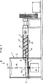
Die in
In geringem Abstand zur Bodenfläche
Wie in
Weiters können zur besseren Zuführung des Materials zur Öffnung
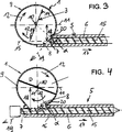
Die in den
Theoretisch ist es auch möglich, dass die Misch- und Zerkleinerungswerkzeuge
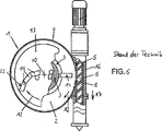
Im Vergleich ist in
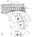
Auf der Höhe des im vorliegenden Fall einzigen Zerkleinerungs- und Mischwerkzeugs
Die Außenkanten der Misch- und Zerkleinerungswerkzeuge
In den in den Figuren dargestellten Beispielen handelt es sich immer um einen komprimierenden Einwellen- bzw. Einschneckenextruder. Alternativ ist jedoch auch die Vorsehung von Doppel- oder Mehrwellenextrudern möglich oder der Einbau von nicht komprimierenden Förderschnecken.In the examples shown in the figures, it is always a compressing single-screw or single-screw extruder. Alternatively, however, the provision of double or multi-screw extruders is possible or the installation of non-compressing screw conveyors.
Im Betrieb wird das aufzubereitende Kunststoffmaterial, meist in Form von Kunststoffabfall, Flaschen oder Folien, über einen offenen Aufgabetrichter in den Aufnahmebehälter
In
Der Extruder
Bei der Ausführungsform gemäß
Der Abstand
Anders ausgedrückt, ist das Skalarprodukt aus einem Richtungsvektor
Das Skalarprodukt ist in
In
In
ZITATE ENTHALTEN IN DER BESCHREIBUNG QUOTES INCLUDE IN THE DESCRIPTION
Diese Liste der vom Anmelder aufgeführten Dokumente wurde automatisiert erzeugt und ist ausschließlich zur besseren Information des Lesers aufgenommen. Die Liste ist nicht Bestandteil der deutschen Patent- bzw. Gebrauchsmusteranmeldung. Das DPMA übernimmt keinerlei Haftung für etwaige Fehler oder Auslassungen.This list of the documents listed by the applicant has been generated automatically and is included solely for the better information of the reader. The list is not part of the German patent or utility model application. The DPMA assumes no liability for any errors or omissions.
Zitierte PatentliteraturCited patent literature
- EP 123771 [0003, 0049] EP 123771 [0003, 0049]
- WO 88/02684 [0006] WO 88/02684 [0006]
Claims (16)
Applications Claiming Priority (2)
| Application Number | Priority Date | Filing Date | Title |
|---|---|---|---|
| ATA600/2010 | 2010-04-14 | ||
| ATA600/2010A AT511362B1 (en) | 2010-04-14 | 2010-04-14 | DEVICE FOR PREPARING PLASTIC MATERIAL |
Publications (1)
| Publication Number | Publication Date |
|---|---|
| DE202011108491U1 true DE202011108491U1 (en) | 2012-03-14 |
Family
ID=44209669
Family Applications (1)
| Application Number | Title | Priority Date | Filing Date |
|---|---|---|---|
| DE201120108491 Expired - Lifetime DE202011108491U1 (en) | 2010-04-14 | 2011-04-13 | Device for processing plastic material |
Country Status (25)
| Country | Link |
|---|---|
| US (2) | US9216521B2 (en) |
| EP (2) | EP2558263B1 (en) |
| JP (1) | JP5530559B2 (en) |
| KR (1) | KR101525381B1 (en) |
| CN (1) | CN102933360B (en) |
| AT (1) | AT511362B1 (en) |
| AU (1) | AU2011241454B2 (en) |
| BR (1) | BR112012026196B8 (en) |
| CA (1) | CA2795962C (en) |
| CL (1) | CL2012002860A1 (en) |
| DE (1) | DE202011108491U1 (en) |
| DK (2) | DK2558263T3 (en) |
| ES (2) | ES2568061T3 (en) |
| HR (2) | HRP20140310T1 (en) |
| HU (1) | HUE027765T2 (en) |
| MX (1) | MX2012011687A (en) |
| PL (2) | PL2689908T3 (en) |
| PT (1) | PT2558263E (en) |
| RS (2) | RS54657B1 (en) |
| RU (1) | RU2532570C2 (en) |
| SI (2) | SI2558263T1 (en) |
| TW (1) | TWI545000B (en) |
| UA (1) | UA106277C2 (en) |
| WO (1) | WO2011127508A1 (en) |
| ZA (1) | ZA201206639B (en) |
Families Citing this family (20)
| Publication number | Priority date | Publication date | Assignee | Title |
|---|---|---|---|---|
| AT504709B1 (en) * | 2006-11-23 | 2008-09-15 | Erema | METHOD AND DEVICE FOR INTRODUCING ADDITIVES |
| AT511362B1 (en) | 2010-04-14 | 2014-01-15 | Erema | DEVICE FOR PREPARING PLASTIC MATERIAL |
| AT512207B1 (en) * | 2011-10-14 | 2015-02-15 | Erema | DEVICE FOR PREPARING PLASTIC MATERIAL |
| AT512212B1 (en) * | 2011-10-14 | 2015-02-15 | Erema | DEVICE FOR PREPARING PLASTIC MATERIAL |
| AT512205B1 (en) * | 2011-10-14 | 2015-02-15 | Erema | DEVICE FOR PREPARING PLASTIC MATERIAL |
| AT512209B1 (en) * | 2011-10-14 | 2015-02-15 | Erema | DEVICE FOR PREPARING PLASTIC MATERIAL |
| AT512222B1 (en) | 2011-10-14 | 2015-02-15 | Erema | DEVICE FOR PREPARING PLASTIC MATERIAL |
| AT512208B1 (en) * | 2011-10-14 | 2015-02-15 | Erema | DEVICE FOR PREPARING PLASTIC MATERIAL |
| AT512146B1 (en) * | 2011-10-14 | 2015-02-15 | Erema | DEVICE FOR PREPARING PLASTIC MATERIAL |
| AT512223B1 (en) * | 2011-10-14 | 2015-02-15 | Erema | DEVICE FOR PREPARING PLASTIC MATERIAL |
| AT512149B1 (en) * | 2011-10-14 | 2015-02-15 | Erema | DEVICE FOR PREPARING PLASTIC MATERIAL |
| AT512148B1 (en) | 2011-10-14 | 2015-02-15 | Erema | DEVICE FOR PREPARING PLASTIC MATERIAL |
| AT512145B1 (en) * | 2011-10-14 | 2015-02-15 | Erema | DEVICE FOR PREPARING PLASTIC MATERIAL |
| AT515363B1 (en) * | 2014-01-28 | 2018-12-15 | Erema Eng Recycling Maschinen & Anlagen Gmbh | chopping tool |
| AT517262A2 (en) * | 2015-06-03 | 2016-12-15 | Next Generation Recyclingmaschinen Gmbh | Processing plant for plastic material |
| CA3110716A1 (en) | 2018-08-29 | 2020-03-05 | Erema Engineering Recycling Maschinen Und Anlagen Gesellschaft M.B.H. | Method and apparatus for processing and/or recycling of materials |
| AT522051B1 (en) * | 2018-12-19 | 2021-04-15 | Next Generation Recyclingmaschinen Gmbh | Processing plant and process for processing plastic material for its recycling |
| AT522425B1 (en) * | 2019-03-20 | 2022-01-15 | Erema Eng Recycling Maschinen & Anlagen Gmbh | peeling screw |
| CN110549517B (en) * | 2019-10-16 | 2021-09-21 | 苏州乐米凡电气科技有限公司 | PVC wire casing recycling processing system |
| US11339712B1 (en) * | 2021-06-25 | 2022-05-24 | Scuderi Group, Inc. | Bottoming cycle power system |
Citations (2)
| Publication number | Priority date | Publication date | Assignee | Title |
|---|---|---|---|---|
| EP0123771A1 (en) | 1983-04-27 | 1984-11-07 | EREMA Engineering Recycling Maschinen und Anlagen Gesellschaft m.b.H. | Apparatus for compounding plastic material |
| WO1988002684A1 (en) | 1986-10-10 | 1988-04-21 | Erema Engineering-Recycling-Maschinen-Anlagen G.M. | Device for processing plastic materials |
Family Cites Families (63)
| Publication number | Priority date | Publication date | Assignee | Title |
|---|---|---|---|---|
| US2927007A (en) * | 1957-04-17 | 1960-03-01 | Braunschweigische Maschb Ansta | Apparatus for the treatment of animal and vegetable materials |
| DE2224209C3 (en) * | 1972-05-18 | 1982-12-30 | Buckau-Walther AG, 4048 Grevenbroich | Device for ejecting the dry, leached chips from a diffusion tower |
| SU536062A1 (en) * | 1974-01-04 | 1976-11-25 | Научно-Исследовательский Конструкторско-Технологический Институт Шинной Промышленности | Device for grinding elastic polymeric materials |
| DE2839446C2 (en) | 1978-09-11 | 1980-09-25 | Thyssen Industrie Ag, 4300 Essen | Device for compacting and agglomerating plastic waste |
| AT368737B (en) | 1980-07-31 | 1982-11-10 | Oesterr Schiffswerften | DEVICE FOR PROCESSING THERMOPLASTIC PLASTIC MATERIAL |
| DE3231237A1 (en) | 1982-08-23 | 1984-02-23 | Dr. Herfeld GmbH & Co KG, 5982 Neuenrade | METHOD FOR COMPRESSING THERMOPLASTIC PLASTIC MATERIAL |
| GB2145351A (en) | 1983-08-24 | 1985-03-27 | Howden James & Co Ltd | Pulverizer |
| AT385234B (en) | 1984-08-01 | 1988-03-10 | Paracon Extrusionstech Gmbh | DEVICE FOR PROCESSING THERMOPLASTIC PLASTIC MATERIAL |
| DE8716077U1 (en) | 1987-12-04 | 1988-02-11 | Plastmachines Gelderland, 8039 Puchheim, De | |
| JPH07112708B2 (en) | 1991-05-02 | 1995-12-06 | ワイケイケイ株式会社 | Automatic conversion and supply device for colored molding material in injection molding machine |
| AT398772B (en) | 1992-04-30 | 1995-01-25 | Erema | METHOD AND DEVICE FOR RECYCLING FUMED PLASTIC MATERIAL |
| AT400315B (en) | 1994-03-01 | 1995-12-27 | Bacher Helmut | Device for degassing a thermoplastic polymer |
| JP2654721B2 (en) | 1993-06-08 | 1997-09-17 | ヘルムト バッケル | Equipment for degassing thermoplastic synthetic plastic materials |
| JPH07148736A (en) * | 1993-11-30 | 1995-06-13 | Tomomichi Uchida | Breaking-off device of waste plastic material delivered from injection molder |
| DE59402323D1 (en) | 1993-12-21 | 1997-05-07 | Helmuth Schulz | DEVICE FOR PROCESSING THERMOPLASTIC PLASTIC GOODS |
| US5783225A (en) | 1993-12-21 | 1998-07-21 | Bacher; Helmut | Apparatus for processing thermoplastic synthetic plastics material |
| AT405726B (en) | 1995-04-11 | 1999-11-25 | Bacher Helmut | DEVICE FOR PROCESSING THERMOPLASTIC PLASTIC GOODS |
| ES2147940T3 (en) | 1995-11-11 | 2000-10-01 | Schafer Elektrotechnik Sonderm | PROCEDURE FOR PROCESSING CONSTRUCTION ELEMENTS OF MIXED SYNTHETIC MATERIALS AND OTHER CONSTRUCTION MATERIALS MIXED WITH THEM, AND DEVICE TO CARRY OUT THE PROCEDURE. |
| IT1295628B1 (en) * | 1997-10-17 | 1999-05-24 | Gamma Meccanica Srl | EQUIPMENT FOR THE FEEDING OF A SCREW EXTRUDER WITH CRUSHED PLASTIC MATERIAL. |
| AT407235B (en) | 1999-04-23 | 2001-01-25 | Bacher Helmut | DEVICE FOR CONTINUOUSLY RECYCLING PLASTIC MATERIAL, PREFERABLY POLYESTER |
| AT407970B (en) | 1999-06-02 | 2001-07-25 | Bacher Helmut | DEVICE AND METHOD FOR PROCESSING, IN PARTICULAR THERMOPLASTIC, PLASTIC MATERIAL |
| JP2001026019A (en) | 1999-07-14 | 2001-01-30 | Sintokogio Ltd | Method for controlling temperature in coating removing device for waste prastic and coating removing device for waste plastic |
| JP4073580B2 (en) | 1999-07-19 | 2008-04-09 | 新東工業株式会社 | Recycling equipment for resin parts with coating film |
| AT411161B (en) | 1999-09-22 | 2003-10-27 | Bacher Helmut | METHOD AND DEVICE FOR RECYCLING PET GOODS |
| AT407972B (en) | 1999-12-02 | 2001-07-25 | Bacher Helmut | DEVICE FOR PRE-TREATING AND SUBJECT PLASTIFICATING OR AGGLOMERING PLASTICS |
| AT412623B (en) | 2000-04-26 | 2005-05-25 | Bacher Helmut | DEVICE AND METHOD FOR PREPARING THERMOPLASTIC PLASTIC GOODS |
| US20020125600A1 (en) | 2000-10-31 | 2002-09-12 | David Horne | Plastic recycling system and process |
| AT410298B (en) | 2001-06-11 | 2003-03-25 | Bacher Helmut | DEVICE FOR FILLING A SNAIL STORED IN A CASE AND METHOD FOR OPERATING SUCH A DEVICE |
| EP1273412A1 (en) | 2001-07-02 | 2003-01-08 | Magma Trade di Mauro Magni & C.snc | Process and apparatus for the production of filled thermoplastic polymers |
| DE10140215A1 (en) | 2001-08-16 | 2003-02-27 | Novum 2000 Gmbh | Thermoplastic scrap processing machine for recycling of thermoplastic plastic materials, includes an additive feed unit prior to a mixer and screw extruder |
| UA1427U (en) | 2001-11-01 | 2002-10-15 | Національний Технічний Університет України "Київський Політехнічний Інститут" | DEVICE FOR CRUSHING MATERIALS |
| AT411235B (en) | 2002-06-05 | 2003-11-25 | Bacher Helmut | Recycled thermoplastic processing plant comprises two evacuated mixing vessels with temperature sensors, an inlet side vacuum sluice and an outlet to an extruder |
| AT411038B (en) | 2002-06-10 | 2003-09-25 | Bacher Helmut | Mixer for homogenization of recycled PET materials has angled blades to lift and disperse material below the tool and blade carrier disc |
| AT503334B1 (en) | 2003-04-01 | 2010-06-15 | Erema | METHOD AND DEVICE FOR PLASTICIZING PLASTIC MATERIAL |
| US20040201142A1 (en) | 2003-04-14 | 2004-10-14 | Robert Rumen | Injection lance for uniformly injecting a steam/ammonia mixture into a fossil fuel combustion stream |
| AT413512B (en) * | 2003-06-05 | 2006-03-15 | Helmut Bacher | DEVICE FOR PREPARING PLASTIC MATERIAL FOR RECYCLING PURPOSES |
| AT413511B (en) | 2003-06-05 | 2006-03-15 | Bacher Helmut | DEVICE FOR PREPARING PLASTIC MATERIAL FOR RECYCLING PURPOSES |
| AT413199B (en) * | 2004-03-17 | 2005-12-15 | Erema | DEVICE FOR PREPARING PLASTIC MATERIAL |
| AT413673B (en) | 2004-07-16 | 2006-04-15 | Erema | DEVICE AND METHOD FOR PREPARING THERMOPLASTIC, RECYCLED PLASTIC MATERIAL |
| US20070102550A1 (en) | 2005-11-07 | 2007-05-10 | Lin Ping H | Plastic grain cutting and transporting mechanism |
| AT503014B1 (en) | 2006-04-27 | 2007-07-15 | Schulz Helmuth | Device for the extrusion of thermoplastic synthetic materials for the production of plastic, comprises an extruder screw mounted on a housing having a plasticizing section at the inlet side, a degassing section and a conveying outlet |
| AT504326B8 (en) | 2006-10-30 | 2008-09-15 | Next Generation Recyclingmasch | DEVICE FOR PREPARING THERMOPLASTIC PLASTIC MATERIAL |
| AT504709B1 (en) | 2006-11-23 | 2008-09-15 | Erema | METHOD AND DEVICE FOR INTRODUCING ADDITIVES |
| AT504854B1 (en) | 2007-02-15 | 2012-08-15 | Erema | METHOD AND DEVICE FOR PREPARING A MATERIAL |
| AT505595B1 (en) | 2007-08-14 | 2009-04-15 | Erema | METHOD AND DEVICE FOR TREATING PLASTIC MATERIAL |
| AT506489B1 (en) * | 2008-02-14 | 2010-12-15 | Erema | METHOD AND DEVICE FOR INJECTION MOLDING OF PLASTIC MATERIAL |
| AT508951B1 (en) | 2009-04-17 | 2012-03-15 | Erema | METHOD AND ARRANGEMENT FOR RECYCLING PLASTIC |
| AT11398U1 (en) | 2009-08-20 | 2010-10-15 | Engel Austria Gmbh | 3-ZONE PLASTIC NECK WITH MIXING PART |
| EP2316562A1 (en) | 2009-10-29 | 2011-05-04 | Bühler AG | Method and device for the treatment of bulk material |
| AT511362B1 (en) | 2010-04-14 | 2014-01-15 | Erema | DEVICE FOR PREPARING PLASTIC MATERIAL |
| AT509323B1 (en) | 2010-04-16 | 2011-08-15 | Erema | METHOD AND DEVICE FOR PREPARING AND CLEANING A POLYMER MATERIAL |
| AT512208B1 (en) | 2011-10-14 | 2015-02-15 | Erema | DEVICE FOR PREPARING PLASTIC MATERIAL |
| AT512223B1 (en) | 2011-10-14 | 2015-02-15 | Erema | DEVICE FOR PREPARING PLASTIC MATERIAL |
| AT512149B1 (en) | 2011-10-14 | 2015-02-15 | Erema | DEVICE FOR PREPARING PLASTIC MATERIAL |
| AT512145B1 (en) | 2011-10-14 | 2015-02-15 | Erema | DEVICE FOR PREPARING PLASTIC MATERIAL |
| AT512207B1 (en) | 2011-10-14 | 2015-02-15 | Erema | DEVICE FOR PREPARING PLASTIC MATERIAL |
| AT512222B1 (en) | 2011-10-14 | 2015-02-15 | Erema | DEVICE FOR PREPARING PLASTIC MATERIAL |
| AT512148B1 (en) | 2011-10-14 | 2015-02-15 | Erema | DEVICE FOR PREPARING PLASTIC MATERIAL |
| AT512209B1 (en) | 2011-10-14 | 2015-02-15 | Erema | DEVICE FOR PREPARING PLASTIC MATERIAL |
| AT512212B1 (en) | 2011-10-14 | 2015-02-15 | Erema | DEVICE FOR PREPARING PLASTIC MATERIAL |
| AT512146B1 (en) | 2011-10-14 | 2015-02-15 | Erema | DEVICE FOR PREPARING PLASTIC MATERIAL |
| AT512205B1 (en) | 2011-10-14 | 2015-02-15 | Erema | DEVICE FOR PREPARING PLASTIC MATERIAL |
| AT512147B1 (en) | 2011-10-14 | 2015-02-15 | Erema | DEVICE FOR PREPARING PLASTIC MATERIAL |
-
2010
- 2010-04-14 AT ATA600/2010A patent/AT511362B1/en active
-
2011
- 2011-04-13 SI SI201130141T patent/SI2558263T1/en unknown
- 2011-04-13 CN CN201180018841.XA patent/CN102933360B/en active Active
- 2011-04-13 CA CA2795962A patent/CA2795962C/en active Active
- 2011-04-13 KR KR1020127029870A patent/KR101525381B1/en active IP Right Grant
- 2011-04-13 AU AU2011241454A patent/AU2011241454B2/en active Active
- 2011-04-13 EP EP20110718234 patent/EP2558263B1/en active Active
- 2011-04-13 PT PT11718234T patent/PT2558263E/en unknown
- 2011-04-13 TW TW100112809A patent/TWI545000B/en active
- 2011-04-13 DE DE201120108491 patent/DE202011108491U1/en not_active Expired - Lifetime
- 2011-04-13 BR BR112012026196A patent/BR112012026196B8/en active IP Right Grant
- 2011-04-13 PL PL13189929T patent/PL2689908T3/en unknown
- 2011-04-13 US US13/641,087 patent/US9216521B2/en active Active
- 2011-04-13 UA UAA201212790A patent/UA106277C2/en unknown
- 2011-04-13 JP JP2013504057A patent/JP5530559B2/en active Active
- 2011-04-13 ES ES13189929.6T patent/ES2568061T3/en active Active
- 2011-04-13 PL PL11718234T patent/PL2558263T3/en unknown
- 2011-04-13 RU RU2012148284/05A patent/RU2532570C2/en active
- 2011-04-13 HU HUE13189929A patent/HUE027765T2/en unknown
- 2011-04-13 DK DK11718234T patent/DK2558263T3/en active
- 2011-04-13 DK DK13189929.6T patent/DK2689908T3/en active
- 2011-04-13 RS RS20160234A patent/RS54657B1/en unknown
- 2011-04-13 WO PCT/AT2011/000180 patent/WO2011127508A1/en active Application Filing
- 2011-04-13 SI SI201130816A patent/SI2689908T1/en unknown
- 2011-04-13 MX MX2012011687A patent/MX2012011687A/en active IP Right Grant
- 2011-04-13 RS RSP20140143 patent/RS53232B/en unknown
- 2011-04-13 EP EP13189929.6A patent/EP2689908B1/en active Active
- 2011-04-13 ES ES11718234T patent/ES2450050T3/en active Active
-
2012
- 2012-09-05 ZA ZA2012/06639A patent/ZA201206639B/en unknown
- 2012-10-12 CL CL2012002860A patent/CL2012002860A1/en unknown
-
2014
- 2014-04-01 HR HRP20140310AT patent/HRP20140310T1/en unknown
-
2015
- 2015-12-10 US US14/965,538 patent/US10173346B2/en active Active
-
2016
- 2016-04-28 HR HRP20160456TT patent/HRP20160456T1/en unknown
Patent Citations (2)
| Publication number | Priority date | Publication date | Assignee | Title |
|---|---|---|---|---|
| EP0123771A1 (en) | 1983-04-27 | 1984-11-07 | EREMA Engineering Recycling Maschinen und Anlagen Gesellschaft m.b.H. | Apparatus for compounding plastic material |
| WO1988002684A1 (en) | 1986-10-10 | 1988-04-21 | Erema Engineering-Recycling-Maschinen-Anlagen G.M. | Device for processing plastic materials |
Also Published As
Similar Documents
| Publication | Publication Date | Title |
|---|---|---|
| EP2689908B1 (en) | Device and method for processing plastic materials | |
| EP2768645B1 (en) | Apparatus for processing plastic material | |
| EP2766157B1 (en) | Apparatus for processing plastic material | |
| EP2766164B1 (en) | Apparatus for processing plastic material | |
| EP2766159B1 (en) | Apparatus for processing plastic material | |
| EP2766166B1 (en) | Apparatus for processing plastic material | |
| EP2766162B1 (en) | Apparatus for processing plastic material | |
| EP2766158B1 (en) | Apparatus for processing plastic material | |
| EP2766161B1 (en) | Apparatus for processing plastic material | |
| EP2766160B1 (en) | Apparatus for processing plastic material | |
| DE202012012571U1 (en) | Device for processing plastic material | |
| DE202012012574U1 (en) | Device for processing plastic material | |
| DE202012012584U1 (en) | Device for processing plastic material |
Legal Events
| Date | Code | Title | Description |
|---|---|---|---|
| R207 | Utility model specification |
Effective date: 20120503 |
|
| R150 | Utility model maintained after payment of first maintenance fee after three years | ||
| R150 | Utility model maintained after payment of first maintenance fee after three years |
Effective date: 20140428 |
|
| R151 | Utility model maintained after payment of second maintenance fee after six years | ||
| R152 | Utility model maintained after payment of third maintenance fee after eight years | ||
| R071 | Expiry of right |