DE202011051467U1 - Lamp holder for an LED lamp, in particular an LED projection lamp - Google Patents
Lamp holder for an LED lamp, in particular an LED projection lamp Download PDFInfo
- Publication number
- DE202011051467U1 DE202011051467U1 DE202011051467U DE202011051467U DE202011051467U1 DE 202011051467 U1 DE202011051467 U1 DE 202011051467U1 DE 202011051467 U DE202011051467 U DE 202011051467U DE 202011051467 U DE202011051467 U DE 202011051467U DE 202011051467 U1 DE202011051467 U1 DE 202011051467U1
- Authority
- DE
- Germany
- Prior art keywords
- heat dissipation
- insert
- tube
- lamp
- lampshade
- Prior art date
- Legal status (The legal status is an assumption and is not a legal conclusion. Google has not performed a legal analysis and makes no representation as to the accuracy of the status listed.)
- Expired - Lifetime
Links
Images


Classifications
-
- F—MECHANICAL ENGINEERING; LIGHTING; HEATING; WEAPONS; BLASTING
- F21—LIGHTING
- F21V—FUNCTIONAL FEATURES OR DETAILS OF LIGHTING DEVICES OR SYSTEMS THEREOF; STRUCTURAL COMBINATIONS OF LIGHTING DEVICES WITH OTHER ARTICLES, NOT OTHERWISE PROVIDED FOR
- F21V29/00—Protecting lighting devices from thermal damage; Cooling or heating arrangements specially adapted for lighting devices or systems
- F21V29/50—Cooling arrangements
- F21V29/70—Cooling arrangements characterised by passive heat-dissipating elements, e.g. heat-sinks
- F21V29/74—Cooling arrangements characterised by passive heat-dissipating elements, e.g. heat-sinks with fins or blades
- F21V29/77—Cooling arrangements characterised by passive heat-dissipating elements, e.g. heat-sinks with fins or blades with essentially identical diverging planar fins or blades, e.g. with fan-like or star-like cross-section
- F21V29/773—Cooling arrangements characterised by passive heat-dissipating elements, e.g. heat-sinks with fins or blades with essentially identical diverging planar fins or blades, e.g. with fan-like or star-like cross-section the planes containing the fins or blades having the direction of the light emitting axis
-
- F—MECHANICAL ENGINEERING; LIGHTING; HEATING; WEAPONS; BLASTING
- F21—LIGHTING
- F21K—NON-ELECTRIC LIGHT SOURCES USING LUMINESCENCE; LIGHT SOURCES USING ELECTROCHEMILUMINESCENCE; LIGHT SOURCES USING CHARGES OF COMBUSTIBLE MATERIAL; LIGHT SOURCES USING SEMICONDUCTOR DEVICES AS LIGHT-GENERATING ELEMENTS; LIGHT SOURCES NOT OTHERWISE PROVIDED FOR
- F21K9/00—Light sources using semiconductor devices as light-generating elements, e.g. using light-emitting diodes [LED] or lasers
- F21K9/20—Light sources comprising attachment means
- F21K9/23—Retrofit light sources for lighting devices with a single fitting for each light source, e.g. for substitution of incandescent lamps with bayonet or threaded fittings
- F21K9/232—Retrofit light sources for lighting devices with a single fitting for each light source, e.g. for substitution of incandescent lamps with bayonet or threaded fittings specially adapted for generating an essentially omnidirectional light distribution, e.g. with a glass bulb
-
- F—MECHANICAL ENGINEERING; LIGHTING; HEATING; WEAPONS; BLASTING
- F21—LIGHTING
- F21V—FUNCTIONAL FEATURES OR DETAILS OF LIGHTING DEVICES OR SYSTEMS THEREOF; STRUCTURAL COMBINATIONS OF LIGHTING DEVICES WITH OTHER ARTICLES, NOT OTHERWISE PROVIDED FOR
- F21V29/00—Protecting lighting devices from thermal damage; Cooling or heating arrangements specially adapted for lighting devices or systems
- F21V29/50—Cooling arrangements
- F21V29/70—Cooling arrangements characterised by passive heat-dissipating elements, e.g. heat-sinks
- F21V29/71—Cooling arrangements characterised by passive heat-dissipating elements, e.g. heat-sinks using a combination of separate elements interconnected by heat-conducting means, e.g. with heat pipes or thermally conductive bars between separate heat-sink elements
- F21V29/713—Cooling arrangements characterised by passive heat-dissipating elements, e.g. heat-sinks using a combination of separate elements interconnected by heat-conducting means, e.g. with heat pipes or thermally conductive bars between separate heat-sink elements in direct thermal and mechanical contact of each other to form a single system
-
- F—MECHANICAL ENGINEERING; LIGHTING; HEATING; WEAPONS; BLASTING
- F21—LIGHTING
- F21V—FUNCTIONAL FEATURES OR DETAILS OF LIGHTING DEVICES OR SYSTEMS THEREOF; STRUCTURAL COMBINATIONS OF LIGHTING DEVICES WITH OTHER ARTICLES, NOT OTHERWISE PROVIDED FOR
- F21V3/00—Globes; Bowls; Cover glasses
-
- F—MECHANICAL ENGINEERING; LIGHTING; HEATING; WEAPONS; BLASTING
- F21—LIGHTING
- F21Y—INDEXING SCHEME ASSOCIATED WITH SUBCLASSES F21K, F21L, F21S and F21V, RELATING TO THE FORM OR THE KIND OF THE LIGHT SOURCES OR OF THE COLOUR OF THE LIGHT EMITTED
- F21Y2105/00—Planar light sources
- F21Y2105/10—Planar light sources comprising a two-dimensional array of point-like light-generating elements
-
- F—MECHANICAL ENGINEERING; LIGHTING; HEATING; WEAPONS; BLASTING
- F21—LIGHTING
- F21Y—INDEXING SCHEME ASSOCIATED WITH SUBCLASSES F21K, F21L, F21S and F21V, RELATING TO THE FORM OR THE KIND OF THE LIGHT SOURCES OR OF THE COLOUR OF THE LIGHT EMITTED
- F21Y2115/00—Light-generating elements of semiconductor light sources
- F21Y2115/10—Light-emitting diodes [LED]
Abstract
Lampenfassung einer LED-Lampe, insbesondere einer LED-Projektionslampe, umfassend ein Wärmeabführungs-Röhrchen (1), eine Kühlrippeneinheit (2), einen Wärmeabführungs-Einsatz (3) und einen Lampenschirm (4); wobei
das Wärmeabführungs-Röhrchen (1) eine Mehrzahl von Einführungsnuten (11) aufweist, die auf dessen Außenumfangswand verteilt angeordnet sind, wobei ein Ende des Wärmeabführungs-Röhrchens mit dem Wärmeabführungs-Einsatz verbunden ist;
die Kühlrippeneinheit (2) eine Mehrzahl von Kühlrippen (21) aufweist, die zum Einführen in die Einführungsnuten (11) auf der Außenumfangswand des Wärmeabführungs-Röhrchens (1) ausgelegt sind;
der Wärmeabführungs-Einsatz (3) scheibenförmig ist und mit dem Ende des Wärmeabführungs-Röhrchens (1) verbunden ist, um eine Aufnahmefläche (F) auszubilden;
der Lampenschirm (4) lichtdurchlässig ist und mit dem Wärmeabführungs-Einsatz (3) verbunden ist;
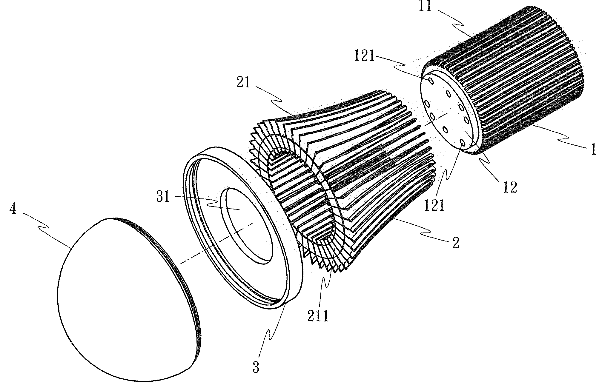
wobei das Wärmeabführungs-Röhrchen, die Kühlrippeneinheit, der Wärmeabführungs-Einsatz und der Lampenschirm so zusammengefügt sind, um eine Lampenfassung einer LED-Lampe auszubilden, bei der das Ende des Wärmeabführungs-Röhrchens (1) fest mit dem Wärmeabführungs-Einsatz (3) verbunden ist, um die Aufnahmefläche zur Aufnahme einer Mehrzahl LED-Einheiten darin...Lamp socket of an LED lamp, in particular an LED projection lamp, comprising a heat dissipation tube (1), a cooling fin unit (2), a heat dissipation insert (3) and a lampshade (4); in which
the heat dissipation tube (1) has a plurality of insertion grooves (11) distributed on the outer peripheral wall thereof, one end of the heat dissipation tube being connected to the heat dissipation insert;
the cooling fin unit (2) has a plurality of cooling fins (21) adapted for insertion into the insertion grooves (11) on the outer peripheral wall of the heat dissipation tube (1);
the heat dissipation insert (3) is disc-shaped and connected to the end of the heat dissipation tube (1) to form a receiving surface (F);
the lampshade (4) is translucent and connected to the heat dissipation insert (3);
wherein the heat dissipation tube, the fin unit, the heat dissipating insert and the lampshade are so assembled to form a lamp socket of an LED lamp, wherein the end of the heat dissipation tube (1) fixedly connected to the heat dissipation insert (3) is to the receiving surface for receiving a plurality of LED units in it ...
Description
Die vorliegende Erfindung betrifft eine Lampenfassung einer LED-Lampe, insbesondere einer LED-Projektionslampe, und betrifft insbesondere eine Lampenfassung mit einem Wärmeabführungs-Röhrchen und einem Wärmeabführungs-Einsatz. Das Ende des Wärmeabführungs-Röhrchens ist mit dem Wärmeabführungs-Einsatz verbunden, um eine geräumige Aufnahmefläche zur Kopplung mit mehreren LED-Beleuchtungseinheiten auszubilden.The present invention relates to a lamp socket of an LED lamp, in particular an LED projection lamp, and in particular relates to a lamp socket with a heat dissipation tube and a heat dissipation insert. The end of the heat dissipation tube is connected to the heat dissipation insert to form a spacious receiving surface for coupling to multiple LED lighting units.
Eine LED-Lampe weist einen geringen Stromverbrauch auf. Ihre LED-Beleuchtungseinheit ist jedoch nicht hitzeresistent. Es ist erforderlich, die Probleme einer hohen Temperatur und einer Wärmeabführung zu lösen. Die Wärmeabführungseigenschaften der Lampenfassung einer herkömmlichen LED-Lampe sind nicht gut. Bei einer herkömmlichen LED-Lampe können nicht viele LED-Beleuchtungseinheiten gehalten werden, weil die Wärmeabführungs-Eigenschaften schlecht sind, so dass nur eine geringe Beleuchtungsstärke bereitgestellt werden kann. Eine herkömmliche LED-Lampe, insbesondere eine LED-Projektionslampe weist eine Lampenfassung, eine LED-Beleuchtungseinheit und einen elektrischen Verbinder bzw. Sockel auf. Der Lampensockel wirkt mit einer isolierenden Hülle zusammen und ist mit der Innenwand der Lampenfassung verbunden, um eine Isolierung zu bewirken. Diese herkömmliche Lampenfassung wird durch Spritzgießen ausgebildet und die Kühlrippen auf der Außenwand der Lampenfassung werden ebenfalls durch ein Metall-Druckguss-Verfahren bzw. durch Extrusion hergestellt. Die Lampenfassung ist schwer und die Anzahl Kühlrippen unterliegt Beschränkungen. Die Kühlrippen können nicht hinsichtlich ihrer Position konzentriert werden und der Wärmeabführungseffekt ist schlecht. Die LED-Lampe ist schwer und vergleichsweise teuer.An LED lamp has a low power consumption. Your LED lighting unit is not heat resistant. It is necessary to solve the problems of high temperature and heat dissipation. The heat dissipation characteristics of the lamp socket of a conventional LED lamp are not good. In a conventional LED lamp, not many LED lighting units can be held because the heat dissipation characteristics are poor, so that only a low illuminance can be provided. A conventional LED lamp, in particular an LED projection lamp, has a lamp socket, an LED lighting unit and an electrical connector or pedestal. The lamp cap cooperates with an insulating sheath and is connected to the inner wall of the lamp socket to effect insulation. This conventional lamp socket is formed by injection molding and the cooling fins on the outer wall of the lamp socket are also manufactured by a metal die-casting method or by extrusion. The lamp socket is heavy and the number of cooling fins is limited. The cooling fins can not be concentrated in position and the heat dissipation effect is poor. The LED lamp is heavy and comparatively expensive.
Die Kühlrippen können in ein Wärmeabführungs-Röhrchen eingeführt werden, um ein Wärmeabführungsgehäuse auszubilden. Das Wärmeabführungsgehäuse weist nur ein kleines Volumen zur Aufnahme einer LED-Beleuchtungseinheit auf, weil die Abmessungen des Wärmeabführungs-Röhrchens gering sind, so dass der Beleuchtungseffekt der LED-Beleuchtungseinheit nicht perfekt ist.The cooling fins may be inserted into a heat dissipation tube to form a heat dissipation housing. The heat dissipation housing has only a small volume for accommodating an LED lighting unit because the dimensions of the heat dissipation pipe are small, so that the lighting effect of the LED lighting unit is not perfect.
Es ist eine Aufgabe der vorliegenden Erfindung, eine Lampenfassung für eine LED-Lampe, insbesondere eine LED-Projektionslampe, bereitzustellen, welche die vorgenannten Unzulänglichkeiten zumindest mindert.It is an object of the present invention to provide a lamp socket for an LED lamp, in particular an LED projection lamp, which at least reduces the aforementioned shortcomings.
Die Lampenfassung gemäß der vorliegenden Erfindung weist ein Wärmeabführungs-Röhrchen, eine Kühlrippeneinheit, einen Wärmeabführungs-Einsatz und einen Lampenschirm auf. Die Kühlrippen-Einheit weist eine Mehrzahl von Kühlrippen auf, die mit dem Wärmeabführungs-Röhrchen gekoppelt sind, insbesondere in dieses eingreifen. Ein Ende des Wärmeabführungs-Röhrchens ist enganliegend mit dem Wärmeabführungs-Einsatz verbunden, um eine geräumige Aufnahmefläche zur Aufnahme einer Mehrzahl von LED-Beleuchtungseinheiten darin auszubilden. Der Wärmeeinführungs-Einsatz ist weiterhin mit dem Lampenschirm verbunden, um die Lampenfassung der erfindungsgemäßen LED-Lampe auszubilden, der mit mehr LED-Beleuchtungseinheiten als herkömmlich verbunden werden kann, um so für bessere Beleuchtungsverhältnisse zu sorgen.The lamp socket according to the present invention comprises a heat dissipation tube, a fin unit, a heat dissipation insert and a lampshade. The cooling fin unit has a plurality of cooling fins, which are coupled to the heat dissipation tube, in particular engage in this. One end of the heat dissipation tube is tightly connected to the heat dissipation insert to form a spacious receiving surface for receiving a plurality of LED lighting units therein. The heat introduction insert is further connected to the lampshade to form the lamp socket of the LED lamp according to the invention, which can be connected to more LED lighting units than conventional, so as to provide better lighting conditions.
Eine weitere Aufgabe der vorliegenden Erfindung besteht darin, eine LED-Lampenfassung einer LED-Lampe, insbesondere einer LED-Projektionslampe, bereitzustellen, wobei das Ende des Wärmeabführungs-Röhrchens einen gestuften Vorsprung aufweist und der Wärmeabführungs-Einsatz eine zentrale Öffnung aufweist, die korrespondierend zu dem gestuften Vorsprung des Wärmeabführungs-Röhrchens ausgebildet ist. Das Wärmeabführungs-Röhrchen und der Wärmeabführungs-Einsatz können mithilfe des gestuften Vorsprungs rasch miteinander verbunden werden, wobei dann ein Eingriff im Bereich der zentralen Öffnung erfolgt.Another object of the present invention is to provide an LED lamp socket of an LED lamp, in particular an LED projection lamp, wherein the end of the heat dissipation tube has a stepped projection and the heat dissipation insert has a central opening corresponding to the stepped projection of the heat dissipation tube is formed. The heat-dissipating tube and the heat-dissipating insert can be quickly connected to each other by means of the stepped projection, in which case an engagement takes place in the region of the central opening.
Eine weitere Aufgabe der vorliegenden Erfindung besteht in der Bereitstellung einer Lampenfassung einer LED-Lampe, wobei der Wärmeabführungs-Einsatz einen Boden aufweist, der mit einem zentralen Vorsprung ausgebildet ist, und wobei das Ende des Wärmeabführungs-Röhrchens einen hohlen Abschnitt aufweist. Der zentrale Vorsprung des Wärmeabführungs-Röhrchens ist auf den hohlen Abschnitt des Wärmeabführungs-Röhrchens so abgestimmt, dass das Wärmeabführungs-Röhrchen und der Wärmeabführungs-Einsatz fest miteinander verbunden werden können.Another object of the present invention is to provide a lamp socket of an LED lamp, wherein the heat dissipation insert has a bottom formed with a central projection, and wherein the end of the heat dissipation tube has a hollow portion. The central projection of the heat dissipation tube is tuned to the hollow portion of the heat dissipation tube so that the heat dissipation tube and the heat dissipation insert can be firmly connected together.
Eine weitere Aufgabe der vorliegenden Erfindung besteht in der Bereitstellung einer Lampenfassung einer LED-Lampe, wobei die Innenwand des Wärmeabführungs-Einsatzes und die Außenwand des Lampenschirms zueinander korrespondierend ausgebildete Verbindungsgebilde aufweisen, so dass der Wärmeabführungs-Einsatz und der Lampenschirm fest miteinander verbunden werden können.Another object of the present invention is to provide a lamp socket of an LED lamp, wherein the inner wall of the heat dissipation insert and the outer wall of the lampshade having mutually corresponding formed connecting structures, so that the heat dissipation insert and the lampshade can be firmly connected to each other.
Eine weitere Aufgabe der vorliegenden Erfindung besteht in der Bereitstellung einer Lampenfassung einer LED-Lampe, wobei die Innenwand des Wärmeabführungs-Einsatzes und die Außenwand des Lampenschirms zueinander korrespondierend ausgebildete Verbindungsgebilde aufweisen, so dass der Lampenschirm rasch und zuverlässig an dem Wärmeabführungs-Einsatz befestigt werden kann.Another object of the present invention is to provide a lamp socket of an LED lamp, wherein the inner wall of the heat dissipation insert and the outer wall of the lampshade have mutually corresponding connection formations, so that the lampshade can be quickly and reliably attached to the heat dissipation insert ,
Figurenübersicht LIST OF FIGURES
Ausführungsbeispiele der vorliegenden Erfindung werden nachfolgend nur in beispielhafter Weise anhand der beigefügten Zeichnungen beschrieben.Embodiments of the present invention will now be described by way of example only with reference to the accompanying drawings.
Wie in den
Das Wärmeabführungs-Röhrchen
Die Kühlrippeneinheit
Der Wärmeabführungs-Einsatz
Der Lampenschirm
Das Wärmeabführungs-Röhrchen
Wie in den
Die Verdrahtungsöffnungen bzw. Kontaktierungsöffnungen
Das Ende des Wärmeabführungs-Röhrchens
Wie in den
Die
Die
Die
Die
Die
Das Wärmeabführungs-Röhrchen
Zusammenfassend weist eine Lampenfassung einer LED-Lampe gemäß der vorliegenden Erfindung ein Wärmeabführungs-Röhrchen, eine Kühlrippeneinheit, eine Wärmeabführungs-Einsatz und einen Lampenschirm auf. Die Kühlrippeneinheit weist eine Mehrzahl von Kühlrippen auf, welche diese umgeben und mit dem Wärmeabführungs-Röhrchen verbunden werden können. Ein Ende des Wärmeabführungs-Röhrchens ist fest mit dem Wärmeabführungs-Einsatz verbunden, um eine geräumige Aufnahmefläche zur Aufnahme einer Mehrzahl von LED-Beleuchtungseinheiten darin auszubilden. Der Wärmeabführungs-Einsatz ist weiterhin mit dem Lampenschirm verbunden, um so die Lampenfassung der LED-Lampe auszubilden, die mit mehreren LED-Beleuchtungseinheiten versehen werden kann.In summary, a lamp socket of an LED lamp according to the present invention has a heat dissipation tube, a fin unit, a heat dissipation insert, and a lampshade. The cooling fin unit has a plurality of cooling fins, which can surround these and be connected to the heat dissipation tube. One end of the heat dissipation tube is fixedly connected to the heat dissipation insert to form a spacious receiving surface for receiving a plurality of LED lighting units therein. The heat dissipating insert is further connected to the lampshade so as to form the lamp socket of the LED lamp, which can be provided with a plurality of LED lighting units.
Wenngleich bestimmte Ausführungsbeispiele nach der vorliegenden Erfindung vorstehend im Detail beschrieben worden sind, was zu Erläuterungszwecken erfolgte, können zahlreiche Modifikationen und Verbesserungen vorgenommen werden, ohne von dem allgemeinen Lösungsgedanken und dem Schutzbereich der vorliegenden Erfindung abzuweichen. Folglich unterliegt die vorliegende Erfindung nur den Beschränkungen, wie durch die beigefügten Schutzansprüche festgelegt.While certain embodiments of the present invention have been described above in detail, which has been done for the purposes of illustration, numerous modifications and enhancements may be made without departing from the general spirit and scope of the present invention. Consequently, the present invention is subject only to the limitations as defined by the appended claims.
Claims (10)
Priority Applications (1)
| Application Number | Priority Date | Filing Date | Title |
|---|---|---|---|
| DE202011051467U DE202011051467U1 (en) | 2011-09-28 | 2011-09-28 | Lamp holder for an LED lamp, in particular an LED projection lamp |
Applications Claiming Priority (1)
| Application Number | Priority Date | Filing Date | Title |
|---|---|---|---|
| DE202011051467U DE202011051467U1 (en) | 2011-09-28 | 2011-09-28 | Lamp holder for an LED lamp, in particular an LED projection lamp |
Publications (1)
| Publication Number | Publication Date |
|---|---|
| DE202011051467U1 true DE202011051467U1 (en) | 2011-11-04 |
Family
ID=45116148
Family Applications (1)
| Application Number | Title | Priority Date | Filing Date |
|---|---|---|---|
| DE202011051467U Expired - Lifetime DE202011051467U1 (en) | 2011-09-28 | 2011-09-28 | Lamp holder for an LED lamp, in particular an LED projection lamp |
Country Status (1)
| Country | Link |
|---|---|
| DE (1) | DE202011051467U1 (en) |
Cited By (2)
| Publication number | Priority date | Publication date | Assignee | Title |
|---|---|---|---|---|
| CN103672813A (en) * | 2013-12-11 | 2014-03-26 | 东莞市闻誉实业有限公司 | Radiator of panel light |
| CN106016208A (en) * | 2016-06-13 | 2016-10-12 | 浙江晨丰科技股份有限公司 | LED lamp radiator and assembly method |
-
2011
- 2011-09-28 DE DE202011051467U patent/DE202011051467U1/en not_active Expired - Lifetime
Cited By (2)
| Publication number | Priority date | Publication date | Assignee | Title |
|---|---|---|---|---|
| CN103672813A (en) * | 2013-12-11 | 2014-03-26 | 东莞市闻誉实业有限公司 | Radiator of panel light |
| CN106016208A (en) * | 2016-06-13 | 2016-10-12 | 浙江晨丰科技股份有限公司 | LED lamp radiator and assembly method |
Similar Documents
| Publication | Publication Date | Title |
|---|---|---|
| DE102009047558B4 (en) | Two-piece LED strip connector for surface mounting and LED assembly | |
| DE102005054422A1 (en) | Led lamp with leds on a heat conducting stand and method of making the Led lamp | |
| DE202012104124U1 (en) | LED light Mittelbau group | |
| DE102013002740A1 (en) | Flat cable with grooved and flat surface | |
| DE202012102799U1 (en) | Connection structure of an LED lamp socket and heat radiating ribs | |
| DE102007055040B4 (en) | Contact element and method for producing a contact element | |
| AT14381U1 (en) | Connection or connection terminal as well as circuit board and lighting system | |
| DE202008003496U1 (en) | LED street lamp | |
| DE202011051467U1 (en) | Lamp holder for an LED lamp, in particular an LED projection lamp | |
| DE102007045400B4 (en) | power plug | |
| DE202009008456U1 (en) | Downlight | |
| DE102013107352A1 (en) | Electrical contact element | |
| EP3165821B1 (en) | Elongated light strip element | |
| DE202017106583U1 (en) | Seamless connection enabling rectangular LED light, where the cables remain hidden | |
| EP2860765A1 (en) | Junction box, and method for mounting a junction box | |
| EP2920852B1 (en) | Socket insert | |
| DE102004034834B4 (en) | Housing and construction kit of housings | |
| DE112017000465T5 (en) | LED lighting device and method of making the same | |
| DE202014007116U1 (en) | Electrical connectors | |
| DE102014112658B4 (en) | Plug for a connector for data cables | |
| DE202010006223U1 (en) | Connector for lamp tubes | |
| DE202010004316U1 (en) | LED bulb of the bulb type and cooling structure | |
| DE202017104773U1 (en) | Ceiling-mounted LED light | |
| EP0401330A1 (en) | Plug-in quartz infrared radiator. | |
| DE20118601U1 (en) | Modular lamp chain |
Legal Events
| Date | Code | Title | Description |
|---|---|---|---|
| R207 | Utility model specification |
Effective date: 20111229 |
|
| R150 | Utility model maintained after payment of first maintenance fee after three years | ||
| R150 | Utility model maintained after payment of first maintenance fee after three years |
Effective date: 20141020 |
|
| R151 | Utility model maintained after payment of second maintenance fee after six years | ||
| R158 | Lapse of ip right after 8 years |