DE202008009875U1 - Cable duct for energy and supply lines - Google Patents
Cable duct for energy and supply lines Download PDFInfo
- Publication number
- DE202008009875U1 DE202008009875U1 DE200820009875 DE202008009875U DE202008009875U1 DE 202008009875 U1 DE202008009875 U1 DE 202008009875U1 DE 200820009875 DE200820009875 DE 200820009875 DE 202008009875 U DE202008009875 U DE 202008009875U DE 202008009875 U1 DE202008009875 U1 DE 202008009875U1
- Authority
- DE
- Germany
- Prior art keywords
- cable duct
- duct according
- profiles
- feature
- visual element
- Prior art date
- Legal status (The legal status is an assumption and is not a legal conclusion. Google has not performed a legal analysis and makes no representation as to the accuracy of the status listed.)
- Expired - Lifetime
Links
- 230000000007 visual effect Effects 0.000 claims description 22
- 229920003023 plastic Polymers 0.000 claims description 3
- 239000011521 glass Substances 0.000 claims description 2
- 239000002985 plastic film Substances 0.000 claims 1
- 210000002414 leg Anatomy 0.000 description 8
- 230000003287 optical effect Effects 0.000 description 4
- 210000000689 upper leg Anatomy 0.000 description 4
- 230000000694 effects Effects 0.000 description 1
- 238000000465 moulding Methods 0.000 description 1
Classifications
-
- H—ELECTRICITY
- H02—GENERATION; CONVERSION OR DISTRIBUTION OF ELECTRIC POWER
- H02G—INSTALLATION OF ELECTRIC CABLES OR LINES, OR OF COMBINED OPTICAL AND ELECTRIC CABLES OR LINES
- H02G3/00—Installations of electric cables or lines or protective tubing therefor in or on buildings, equivalent structures or vehicles
- H02G3/02—Details
- H02G3/04—Protective tubing or conduits, e.g. cable ladders or cable troughs
- H02G3/0406—Details thereof
- H02G3/0418—Covers or lids; Their fastenings
-
- H—ELECTRICITY
- H02—GENERATION; CONVERSION OR DISTRIBUTION OF ELECTRIC POWER
- H02G—INSTALLATION OF ELECTRIC CABLES OR LINES, OR OF COMBINED OPTICAL AND ELECTRIC CABLES OR LINES
- H02G3/00—Installations of electric cables or lines or protective tubing therefor in or on buildings, equivalent structures or vehicles
- H02G3/02—Details
- H02G3/04—Protective tubing or conduits, e.g. cable ladders or cable troughs
- H02G3/0437—Channels
Landscapes
- Engineering & Computer Science (AREA)
- Architecture (AREA)
- Civil Engineering (AREA)
- Structural Engineering (AREA)
- Details Of Indoor Wiring (AREA)
Abstract
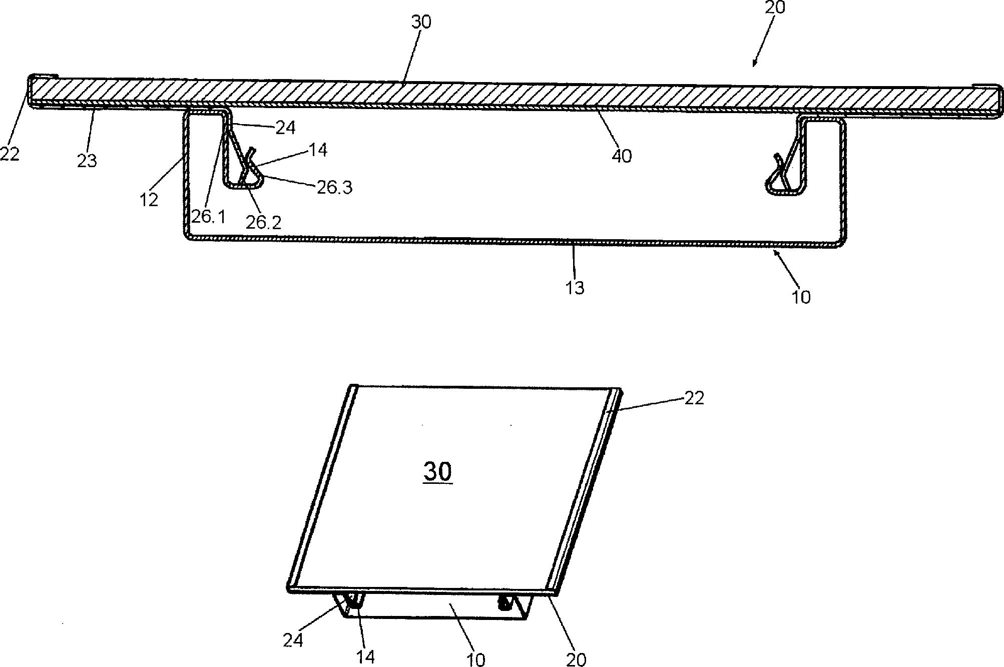
Leitungsführungskanal für Energie- und Versorgungsleitungen, umfassend
– ein Unterteil (10) mit
– einem Boden (13)
– zwei Seitenwänden (12) und
– Deckehalteprofilen (14),
– ein Oberteil (20) mit Formprofilen (24), welche mit den Deckelhalteprofilen (14) des Unterteils (10) kooperieren, gekennzeichnet durch die Merkmale:
– an den Längsseiten des Oberteils (20) ist jeweils ein U-förmig nach innen geneigter Schenkel (22) ausgebildet,
– in den Schenkelaufnahmen ist ein herausnehmbares Sichtelement (30) geführt.Wiring trunking for power and utility lines, comprising
- A lower part (10) with
- a floor (13)
- two side walls (12) and
- decking profiles (14),
- An upper part (20) with shaped profiles (24), which cooperate with the cover holding profiles (14) of the lower part (10), characterized by the features:
- On the longitudinal sides of the upper part (20) is in each case a U-shaped inwardly inclined leg (22),
- In the leg recordings a removable viewing element (30) is guided.
Description
Die vorliegende Erfindung betrifft einen Leitungsführungskanal für Energie- und Versorgungsleitungen gemäß dem Oberbegriff des Anspruchs 1.The The present invention relates to a wiring channel for energy and supply lines according to the preamble of claim 1.
Kabelkanäle oder Leitungsführungskanäle bestehen aus einem Unterteil und einem Oberteil (bzw. Deckel). Je nach Einsatzbereich existieren verschiedene Ausführungsformen und Varianten solcher Kanäle. Oft ist es erwünscht, dass sich der Leitungsführungskanal möglichst unauffällig in den jeweiligen Räumen integriert. Wandkanäle werden daher möglichst so montiert, dass sie bündig mit der Wand abschließen. Nicht immer ist ein solches ”Verstecken” von Kanälen bei Gebäuden oder in Räumen möglich. So gibt es Aufputzkanäle oder Raumsäulen mit Energie- und Datenversorgungsanschlüssen, die optisch sichtbar montiert oder aufgestellt sind.Cable channels or Cable management channels exist from a lower part and an upper part (or cover). Depending on the application There are different embodiments and variants of such channels. Often it is desirable that the wiring channel preferably inconspicuous in the respective rooms integrated. wall channels are therefore possible mounted so that they are flush complete with the wall. Not always such "hiding" channels is included buildings or in rooms possible. So there are surface-mounted channels or room columns with power and data supply connections that are optically visible are mounted or set up.
Die Erfinder haben sich die Aufgabe gestellt, die Funktionalität eines Leitungsführungskanals sowohl in optischer als auch technischer Hinsicht zu erhöhen, indem das Oberteil eines Leitungsführungskanals mit Elementen ausgerüstet wird, um zusätzliche optische und technische Funktionen zu bewirken.The Inventors have set themselves the task, the functionality of a Line guiding channel in both optical and technical terms by: the upper part of a cable trunking equipped with elements will be additional to effect optical and technical functions.
Diese Aufgabe wird gelöst durch einen Leitungsführungskanal mit den Merkmalen des Anspruchs 1.These Task is solved through a wiring channel with the features of claim 1.
Der erfindungsgemäße Leitungsführungskanal besteht aus einem herkömmlichen U-förmigen Unterteil mit beidseitig an den Seitenwänden ausgeformten Deckelhalteprofilen, welche mit den entsprechenden Formprofilen des Deckels kooperieren. Die Besonderheit der Erfindung liegt in der Ausgestaltung und Nutzungsmöglichkeit des Deckels. Dieser besteht erfindungsgemäß aus zwei an der Längsseite ausgebildeten, U-förmig nach innen weisenden Schenkeln, in deren Schenkelaufnahmen ein beliebiges sogenanntes Sichtelement herausnehmbar eingesetzt werden kann. Das Sichtelement ist vorzugsweise eine transparente Kunststoffplatte, eine Scheibe oder ein Display. Hinter dem Sichtelement befindet sich vorzugsweise ein optionales Rückelement, das bevorzugt eine Grafik, ein Bild, eine photographische Darstellung oder eine technische Einrichtung sein kann. Beispielsweise kann das Sichtelement eine Glasscheibe und das Rückelement ein Bild sein.Of the Cable routing channel according to the invention consists of a conventional one U-shaped base with both sides on the side walls shaped lid holding profiles, which with the corresponding Cooperate molding profiles of the cover. The peculiarity of the invention lies in the design and use of the lid. This one exists according to the invention of two on the long side trained, U-shaped inwardly pointing thighs, in the thigh shots any so-called visual element removable can be used. The Viewing element is preferably a transparent plastic plate, a disc or a display. Located behind the visual element preferably an optional back element, preferably a Graphic, an image, a photographic representation or a technical Facility can be. For example, the visual element a Glass pane and the back element to be a picture.
Durch die Kombination von Sichtelement und Rückelement können verschiedene optische Eindrücke oder technische Funktionen erzielt werden. Dabei kann der Monteur den Leitungsführungskanal entsprechend den Kundenwünschen mit den vorhandenen Sichtelementen anpassen.By The combination of visual element and back element can provide different visual impressions or technical functions are achieved. Here, the fitter can Cable trunking according to the customer's wishes adjust with the existing visual elements.
Neben den optischen Möglichkeiten bietet der erfindungsgemäße Leitungsführungskanal auch eine Reihe funktioneller Möglichkeiten. So ist es möglich, in die Schenkelführungen des Deckels eine Anzeigetafel oder ein Display einzusetzen. Auf dem Display können dann Informationen angezeigt werden. Die Versorgungsleitungen für das Display verlaufen verdeckt im Unterteil des Leitungsführungskanals.Next the optical possibilities offers the cable trunking according to the invention also a number of functional possibilities. So it is possible in the leg guides of the lid to insert a scoreboard or a display. On the display can then information will be displayed. The supply lines for the display run concealed in the lower part of the cable trunking.
Der Deckel kann entsprechend den einzelnen Ausführungsformen unterschiedlich gestaltet sein. Die seitlichen Schenkelprofile sind vorzugsweise mit einem Steg verbunden, der entweder parallel oder in einem Winkel zur Ebene des Sichtelements verlaufen kann. Ferner kann der Steg auch durchgehend sein, d. h. die beiden seitlichen Deckelschenkel miteinander verbinden und einen Deckelboden bilden. Dadurch erhält der Deckel zusätzliche Stabilität und das Sichtelement und/oder Rückelement wird von den in dem Unterteil verlaufenden Kabeln und Leitungen räumlich getrennt.Of the Lid may vary according to the individual embodiments be designed. The lateral leg profiles are preferred connected to a bridge, either parallel or at an angle can run to the plane of the visual element. Furthermore, the bridge can also be continuous, d. H. the two lateral lid legs together connect and form a lid bottom. This gives the lid additional Stability and the visual element and / or back element is from the running in the base cables and wires spatial separated.
Die Deckelhalteprofile sind vorzugsweise als U-förmige Laschen ausgebildet, so dass die Formhalteprofile des Oberteils entweder verrastet oder verklemmt werden können.The Lid holding profiles are preferably formed as U-shaped tabs, so that the shape-retaining profiles of the upper part either locked or jammed can be.
Die Erfindung wird in den nachfolgenden Zeichnungen erläutert. Es zeigenThe The invention will be explained in the following drawings. It demonstrate
In
Das
Sichtelement (
In
In
Claims (10)
Priority Applications (2)
| Application Number | Priority Date | Filing Date | Title |
|---|---|---|---|
| DE200820009875 DE202008009875U1 (en) | 2008-07-22 | 2008-07-22 | Cable duct for energy and supply lines |
| EP09008304.9A EP2148402B1 (en) | 2008-07-22 | 2009-06-25 | Cable guidance channel for energy and supply cables |
Applications Claiming Priority (1)
| Application Number | Priority Date | Filing Date | Title |
|---|---|---|---|
| DE200820009875 DE202008009875U1 (en) | 2008-07-22 | 2008-07-22 | Cable duct for energy and supply lines |
Publications (1)
| Publication Number | Publication Date |
|---|---|
| DE202008009875U1 true DE202008009875U1 (en) | 2009-12-03 |
Family
ID=41229163
Family Applications (1)
| Application Number | Title | Priority Date | Filing Date |
|---|---|---|---|
| DE200820009875 Expired - Lifetime DE202008009875U1 (en) | 2008-07-22 | 2008-07-22 | Cable duct for energy and supply lines |
Country Status (2)
| Country | Link |
|---|---|
| EP (1) | EP2148402B1 (en) |
| DE (1) | DE202008009875U1 (en) |
Family Cites Families (7)
| Publication number | Priority date | Publication date | Assignee | Title |
|---|---|---|---|---|
| GB1398848A (en) * | 1971-09-02 | 1975-06-25 | Hitchcock F W | Electrical accessory conduit |
| GB2009523B (en) | 1977-09-13 | 1982-07-07 | Owen W J | Trunking systems for conduits or cables |
| AT395697B (en) | 1990-10-24 | 1993-02-25 | Gerhard Kohlhauser | WALL RAIL PROFILE |
| FR2693849B1 (en) * | 1992-07-17 | 1994-09-30 | Legrand Sa | Channel profile composite assembly or the like. |
| US6437243B1 (en) | 1999-03-03 | 2002-08-20 | Panduit Corp. | Wireway system having a pivotable cover |
| US6374523B1 (en) * | 2000-07-05 | 2002-04-23 | Richard Smith | Holder for mounting to a surface and interchangeably displaying a sheet of material |
| DE20110280U1 (en) | 2001-06-21 | 2001-08-23 | Keller Lichtsysteme GmbH, 72461 Albstadt | Flush-mounted installation rail |
-
2008
- 2008-07-22 DE DE200820009875 patent/DE202008009875U1/en not_active Expired - Lifetime
-
2009
- 2009-06-25 EP EP09008304.9A patent/EP2148402B1/en not_active Not-in-force
Also Published As
| Publication number | Publication date |
|---|---|
| EP2148402A1 (en) | 2010-01-27 |
| EP2148402B1 (en) | 2017-04-19 |
Similar Documents
| Publication | Publication Date | Title |
|---|---|---|
| AT931U1 (en) | SHELF | |
| DE202008009875U1 (en) | Cable duct for energy and supply lines | |
| DE202012101292U1 (en) | Strip, in particular skirting board, wall connection strip or the like end strip | |
| DE4244424C2 (en) | Installation floor | |
| DE202011107398U1 (en) | Floor duct system for cable routing and device installation | |
| DE202008003544U1 (en) | Cable and wiring system for energy, data, air and / or water for attachment to building facades for the renovation or remodeling of buildings | |
| DE202007006989U1 (en) | Cutting lamination for cable ducts | |
| AT5234U1 (en) | FASTENING ARRANGEMENT FOR CABLES | |
| DE19828082A1 (en) | Plastic wiring ducts with side panels for electrical installations | |
| DE2332360B2 (en) | Advertising device with tray and transparent cover - has tray with inwardly directed bead fitting into U-shaped groove in cover | |
| EP1052750B1 (en) | Cable duct | |
| DE102006052258B4 (en) | Cabel Canal | |
| DE9112637U1 (en) | Work table | |
| EP1750340B1 (en) | Channel for installation of cables and apparatus | |
| DE2328235C3 (en) | Multipurpose installation duct for laying walls, in particular for building electrical installations | |
| DE2022946B1 (en) | External cladding for thermal equipment | |
| EP1174067A2 (en) | Edge profile for shower trays sunk in the floor and corresponding manufacturing process | |
| DE20313160U1 (en) | Can be laid in the floor structure | |
| DE202011051583U1 (en) | Furniture | |
| DE29606869U1 (en) | Parapet duct for electrical installations | |
| DE102021132768A1 (en) | Recreational vehicle with a room divider for a sanitary cell | |
| DE1802882C3 (en) | Electrical distribution system embedded in a building ceiling | |
| DE20105148U1 (en) | Boiler enclosure housing | |
| DE202005018605U1 (en) | Channel for wiring arrangement and device assembly, has bar at side wall of inner part at inner side whereby free end of bar is so formed that shank of cover is inserted in corresponding end in detachable manner | |
| DE20313161U1 (en) | Channel for cable routing and / or device installation |
Legal Events
| Date | Code | Title | Description |
|---|---|---|---|
| R207 | Utility model specification |
Effective date: 20100107 |
|
| R150 | Term of protection extended to 6 years | ||
| R150 | Term of protection extended to 6 years |
Effective date: 20111130 |
|
| R082 | Change of representative |
Representative=s name: , |
|
| R151 | Term of protection extended to 8 years | ||
| R151 | Term of protection extended to 8 years |
Effective date: 20140811 |
|
| R152 | Term of protection extended to 10 years | ||
| R071 | Expiry of right |