DE202008009838U1 - Air cushion platform for carrying a manipulator arm and movable robot - Google Patents

Air cushion platform for carrying a manipulator arm and movable robot Download PDF

Info

Publication number
DE202008009838U1
DE202008009838U1 DE202008009838U DE202008009838U DE202008009838U1 DE 202008009838 U1 DE202008009838 U1 DE 202008009838U1 DE 202008009838 U DE202008009838 U DE 202008009838U DE 202008009838 U DE202008009838 U DE 202008009838U DE 202008009838 U1 DE202008009838 U1 DE 202008009838U1
Authority
DE
Germany
Prior art keywords
air cushion
cushion platform
base
platform
engine
Prior art date
Legal status (The legal status is an assumption and is not a legal conclusion. Google has not performed a legal analysis and makes no representation as to the accuracy of the status listed.)
Expired - Lifetime
Application number
DE202008009838U
Other languages
German (de)
Current Assignee (The listed assignees may be inaccurate. Google has not performed a legal analysis and makes no representation or warranty as to the accuracy of the list.)
ROBOTICS Tech LEADERS GmbH
Original Assignee
ROBOTICS Tech LEADERS GmbH
Priority date (The priority date is an assumption and is not a legal conclusion. Google has not performed a legal analysis and makes no representation as to the accuracy of the date listed.)
Filing date
Publication date
Application filed by ROBOTICS Tech LEADERS GmbH filed Critical ROBOTICS Tech LEADERS GmbH
Priority to DE202008009838U priority Critical patent/DE202008009838U1/en
Publication of DE202008009838U1 publication Critical patent/DE202008009838U1/en
Priority to US13/055,404 priority patent/US8464820B2/en
Priority to PCT/EP2009/005326 priority patent/WO2010009878A1/en
Priority to CN200980128565.5A priority patent/CN102105276B/en
Priority to EP09777369A priority patent/EP2326466B1/en
Priority to JP2011519081A priority patent/JP2011528627A/en
Anticipated expiration legal-status Critical
Expired - Lifetime legal-status Critical Current

Links

Classifications

    • BPERFORMING OPERATIONS; TRANSPORTING
    • B25HAND TOOLS; PORTABLE POWER-DRIVEN TOOLS; MANIPULATORS
    • B25JMANIPULATORS; CHAMBERS PROVIDED WITH MANIPULATION DEVICES
    • B25J5/00Manipulators mounted on wheels or on carriages
    • B25J5/007Manipulators mounted on wheels or on carriages mounted on wheels

Landscapes

  • Engineering & Computer Science (AREA)
  • Robotics (AREA)
  • Mechanical Engineering (AREA)
  • Manipulator (AREA)
  • Toys (AREA)

Abstract

Luftkissenplattform (10) zum Tragen eines Manipulatorarms (12), mit:
– einer Basis (26), an deren Unterseite ein Luftkissensystem (32) zum Heben der Basis (26) aus einer Standposition in eine Fahrposition über einem Boden (34) angebracht ist,
– zumindest einer an der Basis (26) befestigten Stellantriebsvorrichtung (22), die wahlweise in ständigem Kontakt mit dem Boden (34) steht, um die Basis (26) am Boden (34) zu bewegen, und
– einer Steuerung, die mit dem Luftkissensystem (32) und der zumindest einen Stellantriebsvorrichtung (22) verbunden ist, um die Stellantriebsvorrichtung (22) nur zu betätigen, wenn die Luftkissenplattform (10) sich in einer Fahrposition befindet.
Air cushion platform (10) for supporting a manipulator arm (12), comprising:
A base (26) on the underside of which an air cushion system (32) for lifting the base (26) from a standing position to a driving position above a floor (34) is mounted,
- At least one of the base (26) fixed actuator device (22) which is optionally in constant contact with the bottom (34) to move the base (26) on the bottom (34), and
- A controller, which is connected to the air bag system (32) and the at least one actuator device (22) to operate the actuator device (22) only when the air cushion platform (10) is in a driving position.

Figure 00000001
Figure 00000001

Description

Die Erfindung betrifft eine Luftkissenplattform zum Tragen eines Manipulatorarms, sowie einen verfahrbaren Roboter, der zum gesteuerten Führen eines Werkzeugs, insbesondere einer Filmkamera vorgesehen ist.The The invention relates to an air cushion platform for supporting a manipulator arm, and a movable robot, which is used for the controlled guidance of a Tool, in particular a film camera is provided.

Bei der Produktion von Filmen und Fernsehsendungen werden oft virtuelle Welten eingesetzt, in denen die Protagonisten wie Schauspieler oder Nachrichtensprecher eingespielt werden. Diese Technik ist unter anderem als Bluescreen- oder Greenscreen-Technik bekannt. Um bei der Aufnahme mittels einer Kamera diese virtuelle Welt später auf das reale Bild entsprechend perspektivisch richtig anzupassen, ist es nötig, die genaue Position des Brennpunkts der Kamera sowie deren Blickrichtung, also ihre Orientierung im Raum zu kennen. Für diesen Zweck werden Roboter eingesetzt, welche Servoachsen mit Drehgebern besitzen, wobei jederzeit (z. B. im 4 ms-Takt) die Stellung der einzelnen Achsen abgefragt und damit die Position der Kamera und ihre Orientierung bestimmt werden kann.at The production of films and television programs often become virtual Used worlds in which the protagonists such as actors or newscasters be recorded. This technique is known as bluescreen or green screen technology. To when recording by means of a Camera this virtual world later to adjust the real image according to perspective correctly is it necessary the exact position of the focal point of the camera and their direction of view, ie to know their orientation in space. For this purpose are robots used, which have servo axes with encoders, at any time (z. B. in 4 ms cycle) queried the position of each axis and to determine the position of the camera and its orientation can.

Bei dieser Technik ist jedoch die Reichweite des Manipulatorarms eingeschränkt, sodass beispielsweise eine Kamerafahrt, bei der jederzeit Position und Orientierung bestimmbar ist, nicht möglich ist. Aufgrund des hohen Gewichts des Manipulatorarms und der Kamera ist ferner der direkte Einsatz von in der Regel filigranen Stellantriebsvorrichtungen, auf denen der Manipulatorarm und die Kamera gelagert ist, nicht oder nur unter hohen Kosten möglich.at However, this technique limits the range of the manipulator arm, so for example, a tracking shot, at any time position and Orientation is determinable, not possible. Due to the high Weight of the manipulator arm and the camera is also the direct Use of usually filigree actuator devices, on which the manipulator arm and the camera is stored, not or only at high cost possible.

Ferner sind im Stand der Technik Luftkissenplattformen bekannt, welche in der Regel per Hand verschiebbar sind. Weiter existieren externe Motorantriebe für Luftkissenplattformen, welche in die Luftkissenplattform eingeklinkt werden können, um diese mittels eines walzenförmigen Antriebs, welcher von einem leistungsstarken Motor angetrieben wird, zu verschieben. Eine reproduzierbare Positionsveränderung ist jedoch bei diesen Systemen nicht möglich.Further Air cushion platforms are known in the art, which usually be moved by hand. Next exist external Motor drives for Air cushion platforms latching into the air cushion platform can be around these by means of a cylindrical Drive powered by a powerful motor to move. A reproducible change in position however, is not possible with these systems.

Der Erfindung liegt somit die Aufgabe zugrunde, eine Luftkissenplattform zum Tragen eines Manipulatorarms und einen verfahrbaren Roboter vorzusehen, bei denen eine genaue und reproduzierbare Positionsänderung möglich ist.Of the Invention is therefore the object of an air cushion platform to provide for carrying a manipulator arm and a traveling robot, where an accurate and reproducible position change possible is.

Diese Aufgabe wird durch die Luftkissenplattform nach Anspruch 1 und den verfahrbaren Roboter nach Anspruch 15 gelöst. Vorteilhafte Ausgestaltungen und Weiterbildungen der Erfindung werden in den Unteransprüchen dargelegt.These The object is achieved by the air cushion platform according to claim 1 and the movable robot according to claim 15 solved. Advantageous embodiments and further developments of the invention are set forth in the subclaims.

Erfindungsgemäß ist eine Luftkissenplattform zum Tragen eines Manipulatorarms vorgesehen, mit einer Basis, an deren Unterseite ein Luftkissensystem zum Heben der Basis aus einer Standposition in eine Fahrposition über einem Boden angebracht ist, zumindest einer an der Basis befestigten Stellantriebsvorrichtung, die in ständigem Kontakt oder wahlweise in ständigem Kontakt mit dem Boden steht, um die Basis am Boden zu bewegen, und einer Steuerung, die mit dem Luftkissensystem und der zumindest einen Stellantriebsvorrichtung verbunden ist, um die Stellantriebsvorrichtung nur zu betätigen, wenn die Luftkissenplattform sich in einer Fahrposition befindet.According to the invention is a Air cushion platform provided for carrying a manipulator arm, with a base, at the bottom of an air cushion system for lifting the base from a standing position to a driving position above a Floor is mounted, at least one attached to the base actuator device, the in constant Contact or alternatively in permanent Contact with the ground stands to move the base to the ground, and a controller associated with the airbag system and the at least an actuator device is connected to the actuator device only to press, if the air cushion platform is in a driving position.

Es ist also eine Luftkissenplattform zum Tragen eines Manipulatorarms vorgesehen, die mittels eines Luftkissensystems leichtgängig schwere Lasten entlang einer Bodenfläche bewegen kann, wobei an der Luftkissenplattform weiter Stellvorrichtungen vorgesehen sind, welche dazu geeignet sind, die Luftkissenplattform positionsgenau zu verschieben, wenn das Luftkissensystem in Betrieb ist.It So is an air cushion platform for carrying a manipulator arm provided, which by means of an airbag system smoothly heavy Loads along a floor surface can move, wherein provided on the air cushion platform more positioning devices which are suitable, the air cushion platform position accurate to move when the air bag system is in operation.

Für den Fall, dass die Basis der Luftkissenplattform nicht plattenförmig ausgebildet ist, sondern wie bei einem Fernsehstativ, einer Pumpe oder einem Pedestal mindestens drei Füße aufweist, oder für eine kostengünstige Verwirklichung des Luftkissensystem ist es von Vorteil, wenn das Luftkissensystem zumindest drei Lufthebekissen umfasst, die um den Schwerpunkt der Luftkissenplattform herum angebracht sind.In the case, that the base of the air cushion platform is not plate-shaped is like a TV stand, a pump or a Pedestal has at least three feet, or for a cost-effective Implementation of the airbag system, it is advantageous if the Air cushion system comprises at least three Lufthebekissen that around the Center of gravity of the air cushion platform are mounted around.

Für die Verwirklichung einer ausgeglichenen Druckeinstellung innerhalb des Luftkissensystems im Falle einer ungleichmäßigen Gewichtsverteilung auf der Basis der Luftkissenplattform ist es besonders zweckmäßig, wenn das Luftkissensystem eine Palette mit einem einzelnen Luftkissen oder einem Luftkissensystem mit einer Vielzahl von miteinander verbundenen Luftkissen umfasst.For the realization a balanced pressure setting within the air bag system in case of uneven weight distribution on the basis of the air cushion platform, it is particularly useful if the airbag system a pallet with a single air cushion or an airbag system having a plurality of interconnected ones Includes air cushion.

Für eine einfache Umsetzung der erfindungsgemäßen Luftkissenplattform umfasst die zumindest eine Stellantriebsvorrichtung eine Motorvorrichtung, die mittels einer Gleitführung vertikal verschiebbar an der Basis gelagert ist.For a simple Implementation of the air cushion platform according to the invention the at least one actuator device comprises a motor device, by means of a sliding guide is mounted vertically displaceable on the base.

Hierbei ist es von Vorteil, wenn die Gleitführung einen Befestigungsbügel mit einem ersten und einem senkrecht auf dem ersten Schenkel stehenden zweiten Schenkel, wobei der erste Schenkel zum Befestigen der Gleitführung an der Basis geeignet ist, ein Schienenelement, das mit dem zweiten Schenkel des Befestigungsbügels verbunden ist, und einen Verfahrschlitten umfasst, der gleitend an dem Schienenelement gelagert und der mit der Motorvorrichtung verbunden ist.in this connection It is advantageous if the sliding guide with a mounting bracket a first and a second vertical standing on the first leg Leg, wherein the first leg for securing the sliding guide on the base is suitable, a rail element, with the second Legs of the mounting bracket is connected, and comprises a carriage, the sliding mounted on the rail member and the with the engine device connected is.

Für die Verwirklichung einer positionsgenauen und reproduzierbaren Verschiebung der Luftkissenplattform ist es hierbei von Vorteil, wenn die Motorvorrichtung einen als Servomotor ausgebildeten Gleichstromgetriebemotor mit einem Geber, und zumindest ein mit einer Motorwelle des Gleichstromgetriebemotors verbundenes Antriebsrad umfasst, welches bei an der Basis befestigter Stellvorrichtung in ständigem Kontakt mit dem Boden steht.For the realization of a positionally accurate and reproducible displacement of the Luftkis senplattform it is advantageous in this case if the motor device comprises a servo motor designed as a direct current geared motor with a transmitter, and at least one connected to a motor shaft of the DC gear motor drive wheel, which is in constant contact with the ground at fixed to the base actuator.

Um eine Beschädigung der Motorvorrichtung aufgrund von seitlichen oder von oben einwirkenden Stößen zu vermeiden, ist es vorteilhaft, wenn die Motorvorrichtung ferner eine Radeinhausung sowie einen Motorschutzbügel zum Schutz des zumindest einen Antriebsrads und des Motors aufweist.Around a damage to avoid the engine device due to lateral or top impacts it is advantageous if the motor device further comprises a Radeinhausung and an engine guard for protecting the at least one drive wheel and the motor.

Hierbei ist es für einen schlupffreien Kontakt der Antriebsräder mit dem Boden von Vorteil, wenn die Motorvorrichtung mittels einer Feder gegen den Boden gedrückt wird, welche wirkungsmäßig zwischen der Motorvorrichtung und der Basis angebracht ist.in this connection is it for a slip-free contact of the drive wheels with the ground advantageous, when the motor device is pressed against the ground by means of a spring, which is effective between the engine device and the base is mounted.

Es ist jedoch auch vorstellbar, dass die Motorvorrichtung ein Zusatzgewicht aufweist, welches oberhalb des zumindest einen Antriebsrads angeordnet ist, um das Antriebsrad infolge der Schwerkraft des Zusatzgewichts in Kontakt mit dem Boden zu halten.It However, it is also conceivable that the engine device is an additional weight which is arranged above the at least one drive wheel is to the drive wheel due to the gravity of the additional weight to keep in contact with the ground.

Um die Umgebung oder auf dem Boden angebrachte Referenzpunkte oder Objekte zuverlässig zu identifizieren, zu klassifizieren, zu vermessen und ihre Position erkennen zu können, um somit die eigene Position und Orientierung der Luftkissenplattform hinsichtlich der Referenzpunkte bestimmen zu können, oder um eine Kollision mit im Raum befindlichen Objekten wie Tischen, Geräten oder Personen vermeiden zu können, ist es besonders von Vorteil, wenn die Luftkissenplattform Sensoren zur Positionserkennung wie einen Laserscanner umfasst.Around the environment or ground reference points or Objects reliably too identify, classify, measure and position to be able to recognize thus regarding the own position and orientation of the air cushion platform with regard to determine the reference points, or a collision with objects in the room such as tables, devices or To avoid persons It is particularly advantageous if the air cushion platform sensors for position detection such as a laser scanner includes.

Für den Fall, dass die Sensoren zur Positionserkennung selbst ein signifikantes Gewicht aufweisen, ist es von Vorteil, wenn die Sensoren zur Positionserkennung als Zusatzgewicht verwendet werden.In the case, that the sensors for position detection itself a significant Having weight, it is advantageous if the sensors for position detection be used as additional weight.

Im Falle von normalen Antriebsrädern ist es für eine Änderung der Fahrtrichtung der Luftkissenplattform zweckmäßig, wenn die Motorvorrichtung dreh- oder schwenkbar an der Gleitführung gelagert ist.in the Trap of normal drive wheels is it for a change the direction of travel of the air cushion platform appropriate when the engine device rotatable or pivotable at the sliding guide is stored.

Es ist jedoch auch vorstellbar, die Motorvorrichtung nicht dreh- oder schwenkbar an der Gleitführung zu lagern. Hierbei ist es besonders zweckmäßig, wenn das zumindest eine Antriebsrad einem Paar von Allseitenrädern entspricht, wobei vorteilhafterweise drei Stellantriebsvorrichtungen an der Basis im Kreis angeordnet und zueinander im 120°-Winkel stehend vorgesehen sind, wobei der gemeinsame Schnittpunkt der drei Motorwellen der Motorvorrichtungen der ungefähre Schwerpunkt des Gesamtsystems ist.It However, it is also conceivable that the engine device does not rotate or swiveling on the sliding guide to store. It is particularly useful if the at least one Drive wheel corresponds to a pair of Allseitenrädern, advantageously three actuator devices arranged at the base in a circle and each other standing at 120 ° angle are provided, wherein the common intersection of the three motor shafts the engine devices the approximate Focus of the overall system is.

Weiter ist erfindungsgemäß ein verfahrbarer Roboter, insbesondere zum gesteuerten Führen eines Werkzeugs, vorgesehen, der eine erfindungsgemäße Luftkissenplattform, einen Sockel, der auf der Luftkissenplattform montiert und von dieser verfahrbar getragen wird, und einen Manipulatorarm umfasst, der mit seinem einen Endabschnitt auf dem Sockel befestigt ist und der mit seinem anderen Ende (oder Hand) ein Werkzeug trägt.Further is a movable robot according to the invention, in particular for controlled guidance a tool, provided that an air cushion platform according to the invention, a pedestal, which is mounted on the air cushion platform and from this is movably carried, and comprises a manipulator, the is fixed with its one end portion on the pedestal and the with his other end (or hand) carries a tool.

Hierbei ist in einer Ausgestaltung der Erfindung das Werkzeug eine Filmkamera, in einer weiteren Ausgestaltung der Erfindung kann das Werkzeug jedoch auch eine Greifhand sein.in this connection in one embodiment of the invention, the tool is a film camera, However, in a further embodiment of the invention, the tool can also be a gripping hand.

Um eine Beschädigung der Antriebsräder aufgrund einer Bewegung des Manipulatorarms auf der Luftkissenplattform während eines Verfahrvorgangs zu vermeiden, ist es von besonderem Vorteil, wenn die Steuerung der Luftkissen plattform mit einer Robotersteuerung verbunden ist, um den Roboter nur zu betätigen, wenn die Luftkissenplattform sich in der Standposition befindet.Around a damage the drive wheels due a movement of the manipulator arm on the air cushion platform during a To avoid movement, it is of particular advantage if the control of the air cushion platform with a robot control is connected to operate the robot only when the air cushion platform is in the standing position.

Die Erfindung wird im Folgenden, beispielsweise anhand der Zeichnungen, näher erläutert. Es zeigen:The Invention is described below, for example with reference to the drawings, explained in more detail. Show it:

1A eine stark vereinfachte schematische Seitenansicht eines Roboters mit einem Manipulatorarm, der eine Filmkamera trägt, in einem Fernsehstudio mit einer erfindungsgemäßen Luftkissenplattform, 1A a highly simplified schematic side view of a robot with a manipulator arm, which carries a film camera, in a television studio with an air cushion platform according to the invention,

1B eine stark vereinfachte schematische Seitenansicht eines Roboters mit einem Manipulatorarm mit einer Greifhand mit der erfindungsgemäßen Luftkissenplattform, 1B a greatly simplified schematic side view of a robot with a manipulator arm with a gripping hand with the air cushion platform according to the invention,

2A eine perspektivische Ansicht der erfindungsgemäßen Luftkissenplattform mit einem darauf montierten Manipulatorarm, 2A a perspective view of the air cushion platform according to the invention with a manipulator mounted thereon,

2B eine Seitenansicht des in 2A gezeigten Aufbaus, 2 B a side view of the in 2A shown construction,

2C eine Draufsicht des in 2A gezeigten Aufbaus, 2C a top view of the in 2A shown construction,

3A eine detaillierte, perspektivische Ansicht einer Stellantriebsvorrichtung gemäß der vorliegenden Erfindung, 3A a detailed, perspective view of an actuator device according to the present invention,

3B eine Seitenansicht auf die erfindungsgemäße Stellantriebsvorrichtung aus 3A, 3B a side view of the actuator device according to the invention from 3A .

3C eine Unteransicht der erfindungsgemäßen Stellantriebsvorrichtung aus 3A, und 3C a bottom view of the actuator device according to the invention 3A , and

4 ein Ausführungsbeispiel einer Anordnung von Stellantriebsvorrichtungen an einer Basis der Luftkissenplattform gemäß der vorliegenden Erfindung, 4 an embodiment of an arrangement of actuator devices on a base of the air cushion platform according to the present invention,

In den verschiedenen Figuren der Zeichnung sind einander entsprechende Bauelemente mit gleichen Bezugszeichen versehen.In The various figures of the drawing are corresponding to each other Components provided with the same reference numerals.
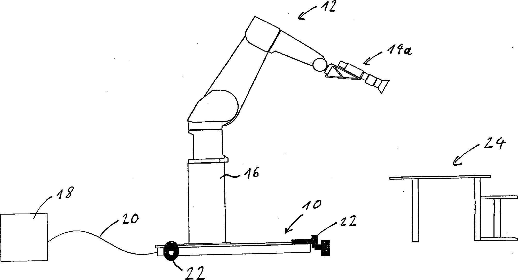
In 1A ist stark vereinfacht und schematisch eine Ausführungsform einer Luftkissenplattform 10 gezeigt, auf welcher ein Manipulatorarm 12 mit einer Kamera 14a auf einem Sockel 16 montiert ist, und welche in einem Fernsehstudio aufgestellt ist. An der Luftkissenplattform 10 ist weiter eine Versorgungs-/Steuereinheit 18 angeschlossen, welche die Luftkissenplattform 10 über eine Versorgungsleitung 20 mit Luft versorgt. Ferner kann in der Versorgungsleitung 20 auch eine Steuerleitung integriert sein, um die Luftkissenplattform 10, den Manipulatorarm 12, die Kamera 14a und Stellantriebsvorrichtungen 22 mit Strom zu versorgen und zu steuern.In 1A is greatly simplified and schematically an embodiment of an air cushion platform 10 shown on which a manipulator arm 12 with a camera 14a on a pedestal 16 is mounted, and which is placed in a television studio. At the air cushion platform 10 is still a supply / control unit 18 connected the air cushion platform 10 via a supply line 20 supplied with air. Furthermore, in the supply line 20 also be integrated with a control line to the air cushion platform 10 , the manipulator arm 12 , the camera 14a and actuator devices 22 be supplied with electricity and control.

In dem in 1A dargestellten Szenario ist die Kamera 14a auf ein Nachrichtensprecherpult 24 gerichtet, um den Nachrichtensprecher vor einer virtuellen Welt abzubilden. Hierbei ist es gemäß dem erfindungsgemäßen Aufbau möglich, die Kamera 14a kontrolliert sowohl durch den Manipulatorarm 12 als auch über die Stellantriebsvorrichtungen 22 zu bewegen, um jederzeit die Position und Orientierung der Kamera zu ermitteln. Mit diesem Aufbau ist es also auch möglich, die Luftkissenplattform 10 an vorbestimmte Orte zu bewegen, um definierte perspektivische Einstellungen in Bezug auf eine virtuelle Welt zu erlangen.In the in 1A The scenario shown is the camera 14a on a newsreader 24 directed to depict the newscaster in front of a virtual world. It is possible according to the structure of the invention, the camera 14a controlled by both the manipulator arm 12 as well as the actuator devices 22 to move at any time to determine the position and orientation of the camera. With this structure, it is also possible, the air cushion platform 10 to move to predetermined locations to obtain defined perspective settings with respect to a virtual world.

Es ist jedoch auch vorstellbar, dass, wie in 1B gezeigt, anstatt der Filmkamera 14a eine Greifhand 14b an dem Manipulatorarm 12 montiert ist, um Güter 25 definiert von einem Ort zu einem anderen zu tragen. Im folgenden soll weiter der Aufbau der Luftkissenplattform 10 mit Manipulatorarm 12 mit der Kamera 14a erläutert werden, wobei jedoch die folgenden Ausführungen ebenfalls für eine Luftkissenplattform 10, bei der der Manipulatorarm 12 eine beispielsweise pneumatische Greifhand 14b oder ein Werkzeug wie ein Messinstrument (ein Laserscanner zum Scannen von Konturen), einen Spezialgreifer zum Tragen von zerbrechlichen Gefäßen wie Reagenzgläser im Laborbereich oder einen Schweißarm trägt, gelten sollen.However, it is also conceivable that, as in 1B shown instead of the movie camera 14a a gripping hand 14b on the manipulator arm 12 is mounted to goods 25 defined from one place to another. The following is the construction of the air cushion platform 10 with manipulator arm 12 with the camera 14a however, the following discussion also applies to an air cushion platform 10 in which the manipulator arm 12 an example pneumatic gripping hand 14b or a tool such as a measuring instrument (a laser scanner for scanning contours), a special gripper for carrying fragile vessels such as test tubes in the laboratory or carrying a welding arm apply.

In den 2A bis 2C sind eine detaillierte perspektivische Ansicht, eine Seitenansicht bzw. eine Draufsicht der Luftkissenplattform 10 mit dem darauf montierten Manipulatorarm 12 und der Kamera 14a gezeigt.In the 2A to 2C FIG. 12 is a detailed perspective view, a side view and a plan view, respectively, of the air cushion platform. FIG 10 with the manipulator arm mounted thereon 12 and the camera 14a shown.

Die Luftkissenplattform 10 weist eine Basis 26 auf, die in dem vorliegenden Ausführungsbeispiel als Sockelplatte ausgebildet ist, welche vorzugsweise aus Stahl hergestellt ist. Auf der Basis 26 ist zentral der Sockel 16 aus Stahl montiert, der im gezeigten Ausführungsbeispiel quaderförmig ist, jedoch auch als Sockelstandrohr ausgebildet sein kann. Auf dem Sockel 16 ist wiederum der Manipulatorarm 12 montiert oder aufgeschraubt, welcher vier Gelenke 28a bis 28d und weitere zwei Gelenke (nicht gezeigt) an seinem Handbereich aufweist, durch welche der an einer Hand oder Halterung 30 angekoppelten Kamera 14a eine Bewegung in sechs räumlichen Freiheitsgraden ermöglicht wird. Weiter ist vorstellbar, dass die Kamera 14a auf einer Schwenk-Neige-Einheit (nicht gezeigt) montiert ist, welche zusätzliche Freiheitsgrade in der Bewegung der Kamera 14a bereitstellt. Die Kamera 14a ist hierbei eine handelsübliche Filmkamera, deren Gewicht bei etwa 2 bis 5 kg liegt. Die Kamera 14a kann entweder über Steuerleitungen in der Versorgungsleitung 20 (1) oder über Funk gesteuert werden. Die Masse des Manipulatorarms beträgt etwa 250 kg, sie kann jedoch bei einem Manipulatorarm mit höherer Traglast 750 kg betragen. Die Masse des Stahlsockels inklusive der als Basis 26 ausgebildeten Stahlsockelplatte beträgt etwa 360 kg. Die Fläche der Basis 26 beträgt 1,5 × 1,5 m2.The air cushion platform 10 has a base 26 on, which is formed in the present embodiment as a base plate, which is preferably made of steel. On the base 26 is central the pedestal 16 made of steel, which is cuboid in the embodiment shown, but may also be designed as a base standpipe. On the pedestal 16 again is the manipulator arm 12 mounted or screwed, which four joints 28a to 28d and another two hinges (not shown) on its hand portion, through which the one on a hand or mount 30 docked camera 14a a movement in six spatial degrees of freedom is possible. It is also conceivable that the camera 14a mounted on a pan-tilt unit (not shown) which provides additional degrees of freedom in the movement of the camera 14a provides. The camera 14a Here is a commercially available film camera whose weight is about 2 to 5 kg. The camera 14a can either via control lines in the supply line 20 ( 1 ) or controlled by radio. The mass of the manipulator arm is about 250 kg, but it can be 750 kg for a manipulator arm with a higher load capacity. The mass of the steel base including the base 26 trained steel base plate is about 360 kg. The area of the base 26 is 1.5 × 1.5 m 2 .

An der Unterseite der Basis 26 ist ein Luftkissensystem 32 (2B) angebracht, welches die Luftkissenplattform 10 aus einer Standposition in eine Fahrposition mittels eines unter der Basis 26 erzeugten Luftkissens bewegt, wodurch die Luftkissenplattform 10 leichtgängig über einen Boden 34 bewegt werden kann. Der Boden 34, welcher in diesem Fall der Boden eines Fernsehstudios ist, ist vorzugsweise ein glatter und ebener Boden, dessen Oberfläche aus Metall oder einem Kunststoff gefertigt oder mit einem Lack bestrichen ist.At the bottom of the base 26 is an airbag system 32 ( 2 B ), which is the air cushion platform 10 from a standing position to a driving position by means of one under the base 26 moved air cushion, causing the air cushion platform 10 smooth over a floor 34 can be moved. The floor 34 , which in this case is the floor of a television studio, is preferably a smooth and level floor, the surface of which is made of metal or plastic or coated with a lacquer.

In dem gezeigten Ausführungsbeispiel in 2B ist das Luftkissensystem 32 als eine einzige Palette ausgebildet, an der eine Vielzahl von kleinen Luftkissen angebracht sind, welche untereinander verschlaucht und jeweils mit einem Durchflussventil versehen sind. Somit erfolgt bei einer ungleichmäßigen Gewichtsverteilung automatisch eine passende Druckeinstellung an den verschiedenen Stellen der Basis 26, wodurch der verfahrbare Roboter aus Luftkissenplattform 10 und dem Aufbau aus Manipulatorarm 12 und Sockel 16 stabil in der Handhabung ist. Es ist jedoch auch vorstellbar, ein Luftkissensystem an der Unterseite der Basis 26 zu montieren, welches aus vier einzelnen kleinen Lufthebekissen besteht, die an den Ecken der Basis 26 montiert sind, wodurch die Kosten des Aufbaus verringert werden. Bei einer un gleichmäßigen Gewichtsverteilung kann jedoch eine Überlastung eines Lufthebekissens oder ein Abheben eines unterbelasteten Lufthebekissens mit einer damit verbundenen Schwingung auftreten, weshalb eine Luftkissenpalette bevorzugt ist.In the embodiment shown in FIG 2 B is the airbag system 32 formed as a single pallet on which a plurality of small air bags are mounted, which are interconnected and each provided with a flow valve. Thus, with an uneven weight distribution, an appropriate pressure adjustment automatically takes place at the various points of the base 26 , making the moveable robot out of air cushion platform 10 and the structure of manipulator 12 and socket 16 stable in handling. However, it is also conceivable to have an air cushion system at the bottom of the base 26 to assemble, which consists of four single small air lifting bags, which at the corners of the base 26 are mounted, whereby the cost of the structure can be reduced. With an un uniform weight distribution can ever However, an overload of an airlift cushion or lift off an under-weighted airlift cushion with an associated vibration occur, which is why an air cushion pallet is preferred.

Wie in den 2A bis 2C gezeigt, sind an einem Randbereich der Basis 26 Stellantriebsvorrichtungen 22 montiert, welche sowohl bei einer Standposition als auch bei einer Fahrposition der Luftkissenplattform 10 in ständigem Kontakt mit dem Boden 34 (2B) stehen. Es ist jedoch auch vorstellbar, die Stellantriebsvorrichtungen 22 so zu montieren, dass sie nur wahlweise in ständigem Kontakt mit dem Boden 34 stehen, also beispielsweise nach oben klappbar sind.As in the 2A to 2C are shown are on a border area of the base 26 Actuator devices 22 mounted, which in both a standing position and a driving position of the air cushion platform 10 in constant contact with the ground 34 ( 2 B ) stand. However, it is also conceivable that the actuator devices 22 to be mounted in such a way that they only optionally in constant contact with the ground 34 are, for example, are hinged upwards.

Eine detaillierte Darstellung einer Stellantriebsvorrichtung 22 ist in den 3A bis 3C in einer perspektivischen Ansicht, einer Seitenansicht und einer Unteransicht gezeigt.A detailed illustration of an actuator device 22 is in the 3A to 3C shown in a perspective view, a side view and a bottom view.

Die Stellantriebsvorrichtung 22 weist eine Gleitführung 36 sowie eine Motorvorrichtung 38 auf. Die Gleitführung 36 umfasst hierbei einen Befestigungsbügel 40 mit einem ersten Schenkel 41a und einem senkrecht darauf stehenden zweiten Schenkel 41b, wobei der erste Schenkel 41a mit Bohrungen 42a, 42b versehen ist, durch welche der Befestigungsbügel 40 an einem Randbereich der Basis 26, vorzugsweise an deren Oberseite, angeschraubt werden kann. Der Befestigungsbügel 40 ist hierbei als Winkel ausgebildet, wobei der zweite Schenkel 41b mit einem Schienenelement 44 verbunden ist, welches zwei zylinderförmige Schienen 46a und 46b aufweist, die im montierten Zustand der Gleitführung 36 an der Basis 26 in einer vertikalen Richtung verlaufen. An dem Schienenelement 44 ist ein Verfahrschlitten 48 gleitend gelagert, wobei dieser Schlittenelemente 50 aufweist, welche die zylinderförmig ausgebildeten Schienen 46a und 46b umfassen und an diesen gleiten. Als Gleitelemente können zwischen den Schlittenelementen 50 und den Schienen 46a, 46b Kunststoffelemente 52 vorgesehen sein, die den Reibungswiderstand zusätzlich verringern. Somit ist bei der Gleitführung 36 der Verfahrschlitten 48 in montiertem Zustand an der Basis 26 in Vertikalrichtung frei beweglich, und in einer Horizontalrichtung aufgrund des Formschlusses zwischen den Schlittenelementen 50 und den Schienen 46a, 46b fest mit der Basis 26 verankert.The actuator device 22 has a sliding guide 36 and a motor device 38 on. The sliding guide 36 this includes a mounting bracket 40 with a first leg 41a and a second leg perpendicular thereto 41b , where the first leg 41a with holes 42a . 42b is provided, through which the mounting bracket 40 at an edge area of the base 26 , preferably at the top, can be screwed. The mounting bracket 40 is here designed as an angle, wherein the second leg 41b with a rail element 44 connected, which two cylindrical rails 46a and 46b has, in the mounted state of the sliding guide 36 at the base 26 in a vertical direction. On the rail element 44 is a carriage 48 slidably mounted, these slide elements 50 which has the cylindrically shaped rails 46a and 46b include and glide on these. As sliding elements can between the carriage elements 50 and the rails 46a . 46b Plastic elements 52 be provided, which additionally reduce the frictional resistance. Thus, in the sliding guide 36 the carriage 48 in assembled condition at the base 26 in the vertical direction freely movable, and in a horizontal direction due to the positive connection between the carriage elements 50 and the rails 46a . 46b stuck with the base 26 anchored.

Als Material für die Gleitführung, welche eine "trockene" Gleitführung ist, ist beispielsweise hart anodisiertes Aluminium als Schienenmaterial geeignet, welches für beste Reib- und Verschleißergebnisse sorgt. Hierbei macht der Verzicht auf Schmierung das System extrem schmutzunempfindlich und ist somit wartungsfrei. Als Gleitkunststoffelement 52 ist beispielsweise der Werkstoff Iglidur J/J200 geeignet, welcher eine maximale Gleitgeschwindigkeit von 15 m/s und eine Anwendungstemperatur von –40°C bis +90°C ermöglicht. Obwohl in dem vorliegenden Ausführungsbeispiel die Gleitschienen 46a und 46b zylinderförmig ausgebildet sind, sind diese nicht auf diese Form beschränkt, sondern können jegliche Art von Querschnittsformen aufweisen, welche entsprechend von den Schlittenelementen 50 umfasst werden.As a material for the sliding, which is a "dry" sliding, for example, hard anodized aluminum is suitable as a rail material, which ensures best friction and wear results. The omission of lubrication makes the system extremely resistant to dirt and is therefore maintenance-free. As sliding plastic element 52 For example, the material Iglidur J / J200 is suitable, which allows a maximum sliding speed of 15 m / s and an application temperature of -40 ° C to + 90 ° C. Although in the present embodiment, the slide rails 46a and 46b are cylindrical, these are not limited to this form, but may have any type of cross-sectional shapes, which in accordance with the carriage elements 50 be included.

An dem Verfahrschlitten 48 ist die Motorvorrichtung 38 befestigt. Die Motorvorrichtung 38 weist einen Motor 54 mit einem Getriebe 55 auf, der als Gleichstromgetriebemotor ausgestaltet ist. Hierbei arbeitet der Motor 54 als Servomotor, um über eine vorbestimmte Anzahl von Umdrehungen eine vorbestimmte Position anfahren zu können. Der Motor 54 ist über das Getriebe 55 mit einer Motorwelle 56 verbunden, auf welcher ein Paar von Antriebsrädern 58a und 58b drehfest montiert ist. Hierbei ist die Motorwelle 56 auf ihrer der Gleitführung 36 zugewandten Seite in einem Aufnahmeloch 60 in einer im Querschnitt U-förmigen Radeinhausung 62 aufgenommen, wobei der Motor 54 an einer der Gleitführung 36 abgewandten Seite der Radeinhausung 62 montiert ist. Hierbei ist der Motor 54 durch einen winkelförmigen Motorschutzbügel 64, welcher durch stiftförmige Befestigungselemente 66 an der Radeinhausung 62 befestigt ist, vor einer Stoßeinwirkung von oben oder von der Seite bei einem Verfahren der Luftkissenplattform 10 geschützt. Die Anordnung des Motors 54 an einer Außenseite und die damit verbundene Anordnung der Antriebsräder 58a und 58b nahe der Gleitführung 36 hat den Vorteil, dass die auf die Gleitführung 36 ausgeübten Kräfte bei einem Verfahren der Basis 26 aufgrund des geringen Hebels zwischen Antriebsrädern und Gleitlager klein gehalten werden.On the carriage 48 is the engine device 38 attached. The engine device 38 has an engine 54 with a gear 55 on, which is designed as a DC geared motor. The engine works here 54 as a servomotor to start over a predetermined number of revolutions to a predetermined position can. The motor 54 is about the gearbox 55 with a motor shaft 56 connected, on which a pair of drive wheels 58a and 58b is rotatably mounted. Here is the motor shaft 56 on her the sliding guide 36 facing side in a receiving hole 60 in a cross-sectionally U-shaped Radeinhausung 62 taken, with the engine 54 on one of the sliding guides 36 opposite side of Radeinhausung 62 is mounted. Here is the engine 54 through an angular engine guard 64 , which by pin-shaped fasteners 66 at the Radeinhausung 62 is fixed, before a shock from above or from the side in a process of the air cushion platform 10 protected. The arrangement of the engine 54 on an outside and the associated arrangement of the drive wheels 58a and 58b near the sliding guide 36 has the advantage of being on the sliding guide 36 exerted forces in a procedure of the basis 26 be kept small due to the low lever between the drive wheels and plain bearings.

Der eingesetzte Motor 54 weist vorzugsweise eine Getriebeuntersetzung des Getriebes 55 von 1/100 auf, wobei er eine Abtriebsdrehzahl von etwa 60 Umdrehungen pro Minute, eine Leistungsaufnahme von 1 bis 100 W, bevorzugterweise 1 bis 10 W, und ein maximales Drehmoment von 150 bis 500 Ncm aufweist. Die Antriebsräder 58a und 58b sind als Allseitenräder ausgestaltet, welche auch unter dem Namen "Omniwheel", "schwedische Räder" oder "Mecanum-Räder" im Stand der Technik bekannt sind. Diese Allseitenräder sind speziell ausgebildete Räder, die an der Umlauffläche eines Hauptrades weitere, meist tonnenförmige Hilfsräder aufweisen, deren Drehachsen beispielsweise im rechtem Winkel zur Drehachse des Hauptrades liegen. Dies erlaubt in der Anwendung, dass diese Räder auch, ohne sich gegenseitig zu behindern, nichtparallel benutzt werden können, wodurch ein Differential nicht benötigt wird. Bei den hier gezeigten paarweise angeordneten Allseitenrädern 58a und 58b sind diese so zueinander an der Motorwelle 56 angeordnet, dass die Räder 58a, 58b gegeneinander um einen Winkel von 45° versetzt sind, um einen ruhigen gleichmäßigen Lauf sicherzustellen. Hierbei ist der Durchmesser der Räder 58a und 58b etwa 60 mm und der Wellendurchmesser etwa 8 mm, wobei diese eine maximale Traglast von 20 kg aufweisen. Obwohl die paarweise Anordnung der Räder 58a, 58b aufgrund des ruhigen Laufs bevorzugt ist, ist es jedoch auch vorstellbar, jeweils nur ein Allseitenrad vom Mecanum-Typ an einer Motorwelle 56 vorzusehen.The used engine 54 preferably has a gear reduction of the transmission 55 from 1/100, having an output speed of about 60 revolutions per minute, a power consumption of 1 to 100 W, preferably 1 to 10 W, and a maximum torque of 150 to 500 Ncm. The drive wheels 58a and 58b are designed as omnidirectional wheels, which are also known under the name "Omniwheel", "Swedish wheels" or "Mecanum wheels" in the art. This Allseitenräder are specially trained wheels that have on the rotating surface of a main wheel more, mostly barrel-shaped auxiliary wheels whose axes of rotation are, for example, at right angles to the axis of rotation of the main wheel. This allows in the application that these wheels can be used non-parallel, without obstructing each other, whereby a differential is not needed. In the here shown paired Allseitenrädern 58a and 58b these are so to each other on the motor shaft 56 arranged that the wheels 58a . 58b offset from each other by an angle of 45 ° to a ru ensure smooth running. Here is the diameter of the wheels 58a and 58b about 60 mm and the shaft diameter about 8 mm, which have a maximum load of 20 kg. Although the paired arrangement of the wheels 58a . 58b is preferred due to the quiet running, but it is also conceivable, in each case only one Mecanum-type all-side wheel on a motor shaft 56 provided.

Bei dem Einsatz von Allseitenräder als Antriebsräder 58a, 58b sind die Stellantriebsvorrichtungen 22, wie in 4 gezeigt, vorzugsweise an drei Seiten der Basis 26 im Kreis und zueinander im 120°-Winkel angeordnet, wobei ein gemeinsamer Schnittpunkt 68 einer gedachten Verlängerung der drei Motorwellen 56 gleichzeitig der ungefähre Schwerpunkt des Gesamtsystems ist. Somit kann die Basis 26 jederzeit in jede Richtung verfahren und darüber hinaus um den gemeinsamen Schnittpunkt 68 gedreht werden.When using all-side wheels as drive wheels 58a . 58b are the actuator devices 22 , as in 4 shown, preferably on three sides of the base 26 arranged in a circle and each other at a 120 ° angle, with a common point of intersection 68 an imaginary extension of the three motor shafts 56 at the same time is the approximate focus of the overall system. Thus, the basis 26 at any time in each direction and beyond the common point of intersection 68 to be turned around.

Obwohl das in den Figuren gezeigte Ausführungsbeispiel mit Stellantriebsvorrichtungen, welche fest mit der Basis 26 verbunden sind und welche Allseitenräder 58a und 58b einsetzen, besonders vorteilhaft ist, ist es jedoch auch vorstellbar, normale Antriebsräder zu verwenden, wobei entweder die Antriebsräder über eine schwenkbare Gelenkwelle mit dem Motor 54 verbunden sind, oder wobei die gesamte Stellantriebsvorrichtung 22 oder die Motorvorrichtung 38 in Bezug auf die Basis 26 in Horizontalrichtung dreh- oder schwenkbar gelagert ist. In beiden Fällen ist dann ein weiterer Stellantrieb vorzusehen, welcher die Auslenkung der Gelenkwelle oder der Motorvorrichtung einstellt.Although the embodiment shown in the figures with actuator devices fixed to the base 26 are connected and which all-side wheels 58a and 58b is particularly advantageous, but it is also conceivable to use normal drive wheels, wherein either the drive wheels via a pivotable propeller shaft with the engine 54 are connected, or wherein the entire actuator device 22 or the engine device 38 in terms of the base 26 Is mounted rotatably or pivotally in the horizontal direction. In both cases, then another actuator is provided, which adjusts the deflection of the propeller shaft or the engine device.

Da die verwendeten Motoren 54 klein und dementsprechend leicht sind, ebenso wie die Motorvorrichtung 38 nicht sehr schwer ist, muss zusätzlich noch ein Gewicht (nicht gezeigt) angebracht werden, um die Motorvorrichtung 38 entsprechend stark auf den Boden zu drücken. Hierbei ist es von Vorteil, dieses Gewicht möglichst nah an der Gleitführung 36 auf der Motorvorrichtung 38, also oberhalb der Antriebsräder 58a, 58b anzubringen, damit beim Absenken oder Heben der Motorvorrichtung 38 keine Verklemmung der Gleitführung 36 auftreten kann. Ferner ist es möglich, statt dem Anbringen einer einfachen Gewichtsmasse auch Gewichte zu verwenden, welche eine Funktion ausführen können, also intelligent sind. Hierfür kommt beispielsweise ein Laserscanner oder ein industrielles Sicherheitssystem beziehungsweise Überwachungssystem in Frage. Dieses System könnte erkennen, sobald sich Personen der Luftkissenplattform 10 nähern und den Antrieb abschalten, um eine Kollision zu vermeiden. Andererseits könnten weiter Sensoren verwendet werden, die eine Positionserkennung ermöglichen, um die Position und Orientierung der Luftkissenplattform 10 in Bezug auf ein am Boden 34 vorgegebenes Referenzsystem zu bestimmen. Es ist jedoch auch vorstellbar, die Motorvorrichtung 38 mittels einer Feder, welche wirkungsmäßig zwischen Basis 26 und Motorvorrichtung 38 angeordnet ist, auf den Boden zu drücken.Because the engines used 54 small and therefore lightweight, as well as the engine device 38 is not very heavy, in addition a weight (not shown) must be attached to the engine device 38 accordingly strong to the ground to press. It is advantageous, this weight as close to the sliding 36 on the engine device 38 So above the drive wheels 58a . 58b to attach, so when lowering or lifting the engine device 38 no jamming of the sliding guide 36 can occur. Further, it is possible to use weights that can perform a function, that is intelligent, instead of attaching a simple weight mass. For this purpose, for example, a laser scanner or an industrial security system or monitoring system in question. This system could detect as soon as people of the air cushion platform 10 approach and shut off the drive to avoid a collision. On the other hand, sensors could be used which allow position detection to the position and orientation of the air cushion platform 10 in terms of one on the ground 34 to determine the specified reference system. However, it is also conceivable, the engine device 38 by means of a spring which operates between base 26 and engine device 38 is arranged to press on the ground.

Die Luftkissenplattform 10 gemäß der vorliegenden Erfindung weist zudem eine Steuerungsvorrichtung auf (nicht gezeigt), welche das Zusammenspiel der drei Stellantriebsvorrichtungen 22, wie in 4 gezeigt, steuert und welche darüber hinaus dafür Sorge trägt, dass die Stellantriebsvorrichtungen 22 nicht betrieben werden, wenn die Luftkissenplattform 10 sich nicht in einer Fahrposition (bei einem Nichtbetrieb des Luftkissensystem) befindet. In dem vorliegenden Ausführungsbeispiel werden drei Stellantriebsvorrichtungen 22 verwendet, es ist jedoch auch möglich mehr als drei Stellantriebsvorrichtungen 22 zu benutzen, wobei beispielsweise bei vier Stellantriebsvorrichtungen 22 diese jeweils paarweise auf gegenüberliegenden Seiten der Basis 26 angeordnet sein können. Es ist jedoch auch vorstellbar, nur zwei Stellantriebsvorrichtungen 22, deren Verbindungslinie durch den ungefähren Schwerpunkt des Gesamtsystems läuft, vorzusehen.The air cushion platform 10 In addition, according to the present invention, a control device (not shown) which controls the interaction of the three actuator devices 22 , as in 4 shown, controls and which, moreover, ensures that the actuator devices 22 not operated when the air cushion platform 10 is not in a driving position (when the airbag system is not operating). In the present embodiment, three actuator devices 22 However, it is also possible more than three actuator devices 22 for example, with four actuator devices 22 these in pairs on opposite sides of the base 26 can be arranged. However, it is also conceivable only two actuator devices 22 whose connecting line runs through the approximate center of gravity of the overall system.

Darüber hinaus ist die Erfindung nicht auf die Verwendung einer vertikal verschiebbaren Gleitführung, welche besonders vorteilhaft ist, beschränkt. So kann beispielsweise die Motorvorrichtung 38 auch über ein Doppelgelenk im Falle eines Paares von Allseitenrädern oder über ein Einfachgelenk im Falle eines einzelnen Allseitenrads an der Basis 26 befestigt sein.In addition, the invention is not limited to the use of a vertically displaceable sliding guide, which is particularly advantageous. For example, the engine device 38 also via a double joint in the case of a pair of all-side wheels or via a single joint in the case of a single all-side wheel at the base 26 be attached.

Bei dem beschriebenen Ausführungsbeispiel dient der Motor 54 nur noch zur Beschleunigung der Luftkissenplattform 10, da aufgrund des Luftkissens im Wesentlichen keine Reibung mehr zwischen Boden 34 und Basis 26 auftritt, welche durch eine Motorkraft 54 überwunden werden müsste. Somit ist es möglich, durch die Verwendung einer Luftkissenplattform Stellantriebsvorrichtungen zu verwenden, welche in der Regel von ihrer Bauart her filigran sind, um somit eine Kameraplattform, welche über 500 kg wiegt, positionsgenau zu verfahren. Hierbei ist es jedoch erforderlich, dass die oben erwähnte Steuerung weiter dafür Sorge trägt, dass sich der Manipulatorarm während der Fahrt nicht bewegt, da aufgrund der hohen Trägheitskräfte ein Verfahren des Manipulatorarms zu hohe Kräfte auf die Antriebsräder 58a, 58b ausüben würde, wodurch entweder ein Verrutschen oder eine Beschädigung der Räder 58a, 58b auftreten könnte. Bei dem Vorsehen von robusten Stellantriebsvorrichtungen ist diese Steuerung jedoch nicht nötig.In the described embodiment, the motor is used 54 only to accelerate the air cushion platform 10 , because due to the air cushion substantially no friction between ground 34 and base 26 which occurs due to an engine power 54 would have to be overcome. Thus, it is possible to use actuator devices by the use of an air cushion platform, which are filigree of their design generally, so as to move a camera platform, which weighs over 500 kg, positionally accurate. In this case, however, it is necessary that the above-mentioned control further ensures that the manipulator arm does not move while driving, as due to the high inertial forces, a method of the manipulator arm too high forces on the drive wheels 58a . 58b exercise, resulting in either slipping or damaging the wheels 58a . 58b could occur. In the provision of robust actuator devices, however, this control is not necessary.

Claims (19)

Luftkissenplattform (10) zum Tragen eines Manipulatorarms (12), mit: – einer Basis (26), an deren Unterseite ein Luftkissensystem (32) zum Heben der Basis (26) aus einer Standposition in eine Fahrposition über einem Boden (34) angebracht ist, – zumindest einer an der Basis (26) befestigten Stellantriebsvorrichtung (22), die wahlweise in ständigem Kontakt mit dem Boden (34) steht, um die Basis (26) am Boden (34) zu bewegen, und – einer Steuerung, die mit dem Luftkissensystem (32) und der zumindest einen Stellantriebsvorrichtung (22) verbunden ist, um die Stellantriebsvorrichtung (22) nur zu betätigen, wenn die Luftkissenplattform (10) sich in einer Fahrposition befindet.Air cushion platform ( 10 ) to carry a Ma nipulator arms ( 12 ), with: - a base ( 26 ), at the bottom of which an air cushion system ( 32 ) for lifting the base ( 26 ) from a standing position to a driving position above a ground ( 34 ), - at least one at the base ( 26 ) fastened actuator device ( 22 ), which may be in constant contact with the ground ( 34 ) stands to the base ( 26 ) on the ground ( 34 ), and - a controller connected to the airbag system ( 32 ) and the at least one actuator device ( 22 ) is connected to the actuator device ( 22 ) only when the air cushion platform ( 10 ) is in a driving position. Luftkissenplattform (10) nach Anspruch 1, dadurch gekennzeichnet, dass das Luftkissensystem (32) zumindest drei Lufthebekissen umfasst, die um den Schwerpunkt der Luftkissenplattform (10) herum angebracht sind.Air cushion platform ( 10 ) according to claim 1, characterized in that the air cushion system ( 32 ) comprises at least three air lift pads around the center of gravity of the air cushion platform ( 10 ) are mounted around. Luftkissenplattform (10) nach Anspruch 1 oder 2, dadurch gekennzeichnet, dass das Luftkissensystem (32) eine Palette mit einem einzelnen Luftkissen oder einem Luftkissensystem mit einer Vielzahl von miteinander verbundenen Luftkissen umfasst.Air cushion platform ( 10 ) according to claim 1 or 2, characterized in that the air cushion system ( 32 ) comprises a single air cushion or air cushion system pallet having a plurality of interconnected airbags. Luftkissenplattform (10) nach einem der vorstehenden Ansprüche, dadurch gekennzeichnet, dass die zumindest eine Stellantriebsvorrichtung (22) eine Motorvorrichtung (38) umfasst, die mittels einer Gleitführung (36) vertikal verschiebbar an der Basis (26) gelagert ist.Air cushion platform ( 10 ) according to one of the preceding claims, characterized in that the at least one actuator device ( 22 ) a motor device ( 38 ), which by means of a sliding guide ( 36 ) vertically displaceable at the base ( 26 ) is stored. Luftkissenplattform (10) nach Anspruch 4, dadurch gekennzeichnet, dass die Gleitführung (36) folgendes umfasst: – einen Befestigungsbügel (40) mit einem ersten Schenkel (41a) und einem senkrecht auf dem ersten Schenkel (41a) stehenden zweiten Schenkel (41b), wobei der erste Schenkel (41a) zum Befestigen der Gleitführung (36) an der Basis (26) geeignet ist, – ein Schienenelement (44), das mit dem zweiten Schenkel (41b) des Befestigungsbügels (40) verbunden ist, und – einen Verfahrschlitten (48), der gleitend an dem Schienenelement (44) gelagert und der mit der Motorvorrichtung (38) verbunden ist.Air cushion platform ( 10 ) according to claim 4, characterized in that the sliding guide ( 36 ) comprises: - a mounting bracket ( 40 ) with a first leg ( 41a ) and one perpendicular to the first leg ( 41a ) standing second leg ( 41b ), wherein the first leg ( 41a ) for fixing the sliding guide ( 36 ) at the base ( 26 ), - a rail element ( 44 ), which with the second leg ( 41b ) of the mounting bracket ( 40 ), and - a carriage ( 48 ) which slides on the rail element ( 44 ) and the with the engine device ( 38 ) connected is. Luftkissenplattform (10) nach Anspruch 4 oder 5, dadurch gekennzeichnet, dass die Motorvorrichtung (38) folgendes umfasst: – einen als Servomotor ausgebildeten Gleichstromgetriebemotor (54) mit einem Geber, und – zumindest ein mit einer Motorwelle (56) des Gleichstromgetriebemotors (54) verbundenes Antriebsrad (58a, 58b), welches bei an der Basis (26) befestigter Stellvorrichtung (22) in ständigem Kontakt mit dem Boden (34) steht.Air cushion platform ( 10 ) according to claim 4 or 5, characterized in that the engine device ( 38 ) comprises: - a direct current geared motor designed as a servomotor ( 54 ) with a sensor, and - at least one with a motor shaft ( 56 ) of the DC geared motor ( 54 ) connected drive wheel ( 58a . 58b ), which at the base ( 26 ) fastened adjusting device ( 22 ) in constant contact with the ground ( 34 ) stands. Luftkissenplattform (10) nach Anspruch 6, dadurch gekennzeichnet, dass die Motorvorrichtung (38) ferner eine Radeinhausung (62) sowie einen Motorschutzbügel (64) zum Schutz des zumindest einen Antriebsrads (58a, 58b) und des Motors (54) aufweist.Air cushion platform ( 10 ) according to claim 6, characterized in that the engine device ( 38 ) a Radeinhausung ( 62 ) and an engine guard ( 64 ) for protecting the at least one drive wheel ( 58a . 58b ) and the engine ( 54 ) having. Luftkissenplattform (10) nach einem der Ansprüche 4 bis 7, dadurch gekennzeichnet, dass die Motorvorrichtung (38) mittels einer Feder gegen den Boden (34) gedrückt wird, welche wirkungsmäßig zwischen der Motorvorrichtung (38) und der Basis (26) angebracht ist.Air cushion platform ( 10 ) according to one of claims 4 to 7, characterized in that the engine device ( 38 ) by means of a spring against the ground ( 34 ) which is operatively connected between the engine 38 ) and the base ( 26 ) is attached. Luftkissenplattform (10) nach einem der Ansprüche 4 bis 8, dadurch gekennzeichnet, dass die Motorvorrichtung (38) ein Zusatzgewicht aufweist, welches oberhalb des zumindest einen Antriebsrads (58a, 58b) angeordnet ist, um das zumindest eine Antriebsrad (58a, 58b) infolge der Schwerkraft des Zusatzgewichts in Kontakt mit dem Boden zu halten.Air cushion platform ( 10 ) according to one of claims 4 to 8, characterized in that the engine device ( 38 ) has an additional weight, which above the at least one drive wheel ( 58a . 58b ) is arranged around the at least one drive wheel ( 58a . 58b ) due to the gravity of the additional weight to keep in contact with the ground. Luftkissenplattform (10) nach einem der vorstehenden Ansprüche, ferner mit Sensoren zur Positionserkennung wie einem Laserscanner.Air cushion platform ( 10 ) according to one of the preceding claims, further comprising sensors for position detection such as a laser scanner. Luftkissenplattform (10) nach Anspruch 9 und 10, dadurch gekennzeichnet, dass die Sensoren zur Positionserkennung als Zusatzgewicht verwendet werden.Air cushion platform ( 10 ) according to claim 9 and 10, characterized in that the sensors are used for position detection as additional weight. Luftkissenplattform (10) nach einem der Ansprüche 4 bis 11, dadurch gekennzeichnet, dass die Motorvorrichtung (38) dreh- oder schwenkbar an der Gleitführung (36) gelagert ist.Air cushion platform ( 10 ) according to one of claims 4 to 11, characterized in that the engine device ( 38 ) rotatable or pivotable on the sliding guide ( 36 ) is stored. Luftkissenplattform (10) nach einem der Ansprüche 4 bis 11, dadurch gekennzeichnet, dass das zumindest eine Antriebsrad (58a, 58b) einem Paar von Allseitenrädern entspricht.Air cushion platform ( 10 ) according to one of claims 4 to 11, characterized in that the at least one drive wheel ( 58a . 58b ) corresponds to a pair of all-sides wheels. Luftkissenplattform (10) nach Anspruch 13, dadurch gekennzeichnet, dass drei Stellantriebsvorrichtungen (22) an der Basis (26) im Kreis angeordnet und zueinander im 120°-Winkel stehend vorgesehen sind, wobei der gemeinsame Schnittpunkt (68) der drei Motorwellen (56) der Motorvorrichtungen (38) der ungefähre Schwerpunkt des Gesamtsystems ist.Air cushion platform ( 10 ) according to claim 13, characterized in that three actuator devices ( 22 ) at the base ( 26 ) are arranged in a circle and are provided standing one another at an angle of 120 °, wherein the common point of intersection ( 68 ) of the three motor shafts ( 56 ) of the engine devices ( 38 ) is the approximate center of gravity of the overall system. Verfahrbarer Roboter, insbesondere zum gesteuerten Führen eines Werkzeugs (14a, 14b) mit: – einer Luftkissenplattform (10) nach einem der vorstehenden Ansprüche, – einem Sockel (16), der auf der Luftkissenplattform (10) montiert und von dieser verfahrbar getragen wird, und – einem Manipulatorarm (12), der mit seinem einen Endabschnitt auf dem Sockel (16) befestigt ist und der mit seinem anderen Ende (30) ein Werkzeug (14a, 14b) trägt.Mobile robot, in particular for the controlled guidance of a tool ( 14a . 14b ) with: - an air cushion platform ( 10 ) according to one of the preceding claims, - a pedestal ( 16 ) mounted on the air cushion platform ( 10 ) and is carried by this movable, and - a manipulator arm ( 12 ), which with its one end section on the pedestal ( 16 ) and the one with its other end ( 30 ) a tool ( 14a . 14b ) wearing. Verfahrbarer Roboter nach Anspruch 15, 16 oder 17, dadurch gekennzeichnet, dass der Manipulatorarm (12) zwischen seinem anderen Ende (30) und dem Werkzeug (14a, 14b) eine Schwenk-Neige-Einheit aufweist, an welche das Werkzeug (14a, 14b) gekoppelt ist.Movable robot according to claim 15, 16 or 17, characterized in that the manipulator arm ( 12 ) between its other end ( 30 ) and the tool ( 14a . 14b ) has a pan-tilt unit to which the tool ( 14a . 14b ) is coupled. Verfahrbarer Roboter nach Anspruch 15 oder 16, dadurch gekennzeichnet, dass das Werkzeug (14a, 14b) eine Filmkamera (14a) ist.Movable robot according to claim 15 or 16, characterized in that the tool ( 14a . 14b ) a movie camera ( 14a ). Verfahrbarer Roboter nach Anspruch 15 oder 16, dadurch gekennzeichnet, dass das Werkzeug (14a, 14b) eine Greifhand (14b) ist.Movable robot according to claim 15 or 16, characterized in that the tool ( 14a . 14b ) a gripping hand ( 14b ). Roboter nach einem der Ansprüche 15 bis 18, dadurch gekennzeichnet, dass die Steuerung der Luftkissenplattform (10) mit einer Robotersteuerung verbunden ist, um den Roboter nur zu betätigen, wenn die Luftkissenplattform (10) sich in der Standposition befindet.Robot according to one of claims 15 to 18, characterized in that the control of the air cushion platform ( 10 ) is connected to a robot controller in order to operate the robot only when the air cushion platform ( 10 ) is in the standing position.
DE202008009838U 2008-07-22 2008-07-22 Air cushion platform for carrying a manipulator arm and movable robot Expired - Lifetime DE202008009838U1 (en)

Priority Applications (6)

Application Number Priority Date Filing Date Title
DE202008009838U DE202008009838U1 (en) 2008-07-22 2008-07-22 Air cushion platform for carrying a manipulator arm and movable robot
US13/055,404 US8464820B2 (en) 2008-07-22 2009-07-22 Air cushion platform for carrying a manipulator arm and movable robot
PCT/EP2009/005326 WO2010009878A1 (en) 2008-07-22 2009-07-22 Air cushion platform for carrying a manipulator arm and moveable robot
CN200980128565.5A CN102105276B (en) 2008-07-22 2009-07-22 Air-cushion platforms for carrying robotic arms and mobile robots
EP09777369A EP2326466B1 (en) 2008-07-22 2009-07-22 Air cushion platform for carrying a manipulator arm and moveable robot
JP2011519081A JP2011528627A (en) 2008-07-22 2009-07-22 Air cushion platform and mobile robot to carry manipulator arm

Applications Claiming Priority (1)

Application Number Priority Date Filing Date Title
DE202008009838U DE202008009838U1 (en) 2008-07-22 2008-07-22 Air cushion platform for carrying a manipulator arm and movable robot

Publications (1)

Publication Number Publication Date
DE202008009838U1 true DE202008009838U1 (en) 2008-10-23

Family

ID=39877610

Family Applications (1)

Application Number Title Priority Date Filing Date
DE202008009838U Expired - Lifetime DE202008009838U1 (en) 2008-07-22 2008-07-22 Air cushion platform for carrying a manipulator arm and movable robot

Country Status (6)

Country Link
US (1) US8464820B2 (en)
EP (1) EP2326466B1 (en)
JP (1) JP2011528627A (en)
CN (1) CN102105276B (en)
DE (1) DE202008009838U1 (en)
WO (1) WO2010009878A1 (en)

Cited By (4)

* Cited by examiner, † Cited by third party
Publication number Priority date Publication date Assignee Title
WO2016023636A1 (en) * 2014-08-14 2016-02-18 Kuka Roboter Gmbh Carrier system for a manipulator
DE102016201687A1 (en) * 2016-02-04 2017-08-10 Robomotion Gmbh System and method for positioning a robot cell relative to a workstation
CN113371047A (en) * 2021-04-20 2021-09-10 四川川交路桥有限责任公司 Automatic trolley for carrying materials for processing reinforcing steel bars
DE102009040951B4 (en) 2009-09-11 2023-08-10 Ralf Bär Handling/stacking device for pallets, containers or the like

Families Citing this family (21)

* Cited by examiner, † Cited by third party
Publication number Priority date Publication date Assignee Title
DE202011003666U1 (en) * 2011-03-07 2012-06-12 Staubli Faverges Camera system with six axes of rotation for moving a camera
DE102012003690A1 (en) * 2012-02-23 2013-08-29 Kuka Roboter Gmbh Mobile robot
CN102941566B (en) * 2012-11-29 2015-07-08 浙江纺织服装职业技术学院 Object moving robot with soft fingers
PT2821159T (en) * 2013-07-01 2016-11-16 Comau Spa Tool head for performing industrial operations having a wireless monitoring system
DE202014104604U1 (en) 2014-04-09 2015-07-13 Kuka Systems Gmbh applicator
WO2015171611A1 (en) * 2014-05-05 2015-11-12 Health Research, Inc. Clinical intravital microscope
FR3021574B1 (en) * 2014-05-27 2019-04-05 Commissariat A L`Energie Atomique Et Aux Energies Alternatives COBOTIC MANIPULATOR
CN104097707A (en) * 2014-07-31 2014-10-15 四川阿泰因机器人智能装备有限公司 Ground self-adaption type omnidirectional wheel device
US10060475B2 (en) 2014-12-24 2018-08-28 Teradyne, Inc. Braking system
CN104493830A (en) * 2014-12-26 2015-04-08 浙江工业大学 Supermarket service robot
CN104965454A (en) * 2015-06-26 2015-10-07 深圳市兆通影视科技有限公司 Control system of studio robot
CN105479129B (en) * 2015-12-23 2017-04-12 常熟理工学院 Carrying and docking assembly for large-size heavy-load cylindrical workpieces
CN105835971A (en) * 2016-04-29 2016-08-10 中国航空工业集团公司北京长城航空测控技术研究所 Air cushion type robot moving platform and control method thereof
CN106113073B (en) * 2016-07-18 2019-01-01 嵊州市大川机器人有限公司 A PCB board handling robot with a rotating execution end
JP2019063878A (en) * 2017-09-28 2019-04-25 ファナック株式会社 Industrial machine and its transfer mechanism
CN107838133A (en) * 2017-11-10 2018-03-27 广东电网有限责任公司东莞供电局 High-voltage contact dry ice cleaning robot for electric power overhead operation
CN108381509B (en) * 2018-03-19 2021-03-02 京东方科技集团股份有限公司 Intelligent grasping device and control method thereof, and intelligent grasping control system
US10974396B2 (en) * 2018-06-22 2021-04-13 Southwest Research Institute Robotic system for surface treatment of vehicles
US11975486B2 (en) * 2020-02-11 2024-05-07 Board Of Trustees Of The University Of Arkansas Swarm manufacturing for smart factory
CN116783565A (en) * 2021-01-21 2023-09-19 索尼集团公司 Information processing device, mobile device and information processing system
CN116512214B (en) * 2023-05-18 2023-10-20 广州中益机械有限公司 Welding robot for welding sheet metal of vehicle body

Family Cites Families (11)

* Cited by examiner, † Cited by third party
Publication number Priority date Publication date Assignee Title
US3295700A (en) * 1963-03-08 1967-01-03 Siemens Ag Method and apparatus for handling radioactive materials
US3950038A (en) * 1972-06-12 1976-04-13 Aero-Go Engineering & Development Co. Fluid bearing track device
US4440253A (en) * 1981-07-06 1984-04-03 Bertil Pernum Crawler-type transport apparatus
US4567957A (en) * 1983-11-23 1986-02-04 American Industrial Research, Inc. Air pallet with endless belt interface
DE9100213U1 (en) * 1991-01-09 1991-03-28 Siemens AG, 8000 München Robot with base
CN2410200Y (en) * 1999-10-12 2000-12-13 刘秀琴 Heavy-duty lifting air-cushion vehicle
DE102006026132A1 (en) 2006-06-03 2007-06-21 Daimlerchrysler Ag Handling system for moving work piece e.g. vehicle body, has industrial robot, where drive unit is not operated on supporting device and supporting device is moved through carrier unit by suspension system in coupled position of robot
JP4243766B2 (en) * 2006-10-02 2009-03-25 Smc株式会社 Non-contact transfer device
US7891446B2 (en) * 2006-10-06 2011-02-22 Irobot Corporation Robotic vehicle deck adjustment
DE102007011028A1 (en) * 2007-03-07 2007-12-20 Daimlerchrysler Ag System for producing a chassis in commercial vehicle construction comprises an industrial robot which is moved on a guided air cushion support
KR100866843B1 (en) * 2007-04-24 2008-11-04 주식회사 포스코 Air flotation transport system and air flotation transport device using the same

Cited By (6)

* Cited by examiner, † Cited by third party
Publication number Priority date Publication date Assignee Title
DE102009040951B4 (en) 2009-09-11 2023-08-10 Ralf Bär Handling/stacking device for pallets, containers or the like
WO2016023636A1 (en) * 2014-08-14 2016-02-18 Kuka Roboter Gmbh Carrier system for a manipulator
DE102016201687A1 (en) * 2016-02-04 2017-08-10 Robomotion Gmbh System and method for positioning a robot cell relative to a workstation
DE102016201687B4 (en) * 2016-02-04 2025-11-13 Robomotion Gmbh System and method for positioning a robot cell relative to a workstation
CN113371047A (en) * 2021-04-20 2021-09-10 四川川交路桥有限责任公司 Automatic trolley for carrying materials for processing reinforcing steel bars
CN113371047B (en) * 2021-04-20 2022-10-18 四川川交路桥有限责任公司 Automatic trolley for carrying materials for processing reinforcing steel bars

Also Published As

Publication number Publication date
CN102105276B (en) 2014-05-07
CN102105276A (en) 2011-06-22
EP2326466A1 (en) 2011-06-01
US8464820B2 (en) 2013-06-18
US20110174563A1 (en) 2011-07-21
EP2326466B1 (en) 2012-06-20
WO2010009878A1 (en) 2010-01-28
JP2011528627A (en) 2011-11-24

Similar Documents

Publication Publication Date Title
DE202008009838U1 (en) Air cushion platform for carrying a manipulator arm and movable robot
DE102015120058B3 (en) Coupling device and method for coupling a mobile process device
DE60127989T2 (en) DEVICES FOR GENERATING FORCE AND TORQUE
EP1225139B1 (en) Turning device
DE102012003690A1 (en) Mobile robot
DE102010027280A1 (en) Robot integrated workplace
EP2452664B1 (en) Operating table
DE102017106468A1 (en) Rotativeaufeaufschlagen a manufacturing plate for additive manufacturing
DE9414820U1 (en) Industrial robots
EP3220413A1 (en) Service device
EP2892692B1 (en) Displacement system for an assembly bench or a welding bench
DE10216571A1 (en) Device for moving a working head in space
DE102020109341B3 (en) Stabilization device and method for stabilizing a fastening component
EP3075494A1 (en) Working equipment and a working method
DE102016208331B3 (en) Robot gripper with a drive device
DE202013105203U1 (en) working device
DE102013206696B4 (en) Device and a method for controlling a handling device
DE3704952A1 (en) Industrial robots for working and/or handling objects, in particular for assembling the latter
DE102015210914B4 (en) Coordinate measuring machine with a movable traverse and method for producing such a coordinate measuring machine
DE102019201797A1 (en) Turning stand
DE102019129723A1 (en) Human-robot assembly system for the robot-assisted collaborative assembly of a large-dimensional assembly object
DE202008005421U1 (en) Robotics system
DE102021212036A1 (en) Mobile computed tomography system
DE102024200693B3 (en) Mobile device
DE102024113472A1 (en) Self-propelled load handling and transport device

Legal Events

Date Code Title Description
R207 Utility model specification

Effective date: 20081127

R150 Utility model maintained after payment of first maintenance fee after three years

Effective date: 20111130

R151 Utility model maintained after payment of second maintenance fee after six years

Effective date: 20140722

R152 Utility model maintained after payment of third maintenance fee after eight years
R071 Expiry of right