DE19917618B4 - Measuring device for the dielectric constant of a liquid and associated method - Google Patents

Measuring device for the dielectric constant of a liquid and associated method Download PDF

Info

Publication number
DE19917618B4
DE19917618B4 DE19917618A DE19917618A DE19917618B4 DE 19917618 B4 DE19917618 B4 DE 19917618B4 DE 19917618 A DE19917618 A DE 19917618A DE 19917618 A DE19917618 A DE 19917618A DE 19917618 B4 DE19917618 B4 DE 19917618B4
Authority
DE
Germany
Prior art keywords
pulse signal
electrode
dielectric constant
measuring device
measuring
Prior art date
Legal status (The legal status is an assumption and is not a legal conclusion. Google has not performed a legal analysis and makes no representation as to the accuracy of the status listed.)
Revoked
Application number
DE19917618A
Other languages
German (de)
Other versions
DE19917618A1 (en
Inventor
Katsuaki Yasui
Mitsuhiro Ono
Susumu Nagano
Current Assignee (The listed assignees may be inaccurate. Google has not performed a legal analysis and makes no representation or warranty as to the accuracy of the list.)
Mitsubishi Electric Corp
Original Assignee
Mitsubishi Electric Corp
Priority date (The priority date is an assumption and is not a legal conclusion. Google has not performed a legal analysis and makes no representation as to the accuracy of the date listed.)
Filing date
Publication date
Family has litigation
First worldwide family litigation filed litigation Critical https://patents.darts-ip.com/?family=17859850&utm_source=google_patent&utm_medium=platform_link&utm_campaign=public_patent_search&patent=DE19917618(B4) "Global patent litigation dataset” by Darts-ip is licensed under a Creative Commons Attribution 4.0 International License.
Application filed by Mitsubishi Electric Corp filed Critical Mitsubishi Electric Corp
Publication of DE19917618A1 publication Critical patent/DE19917618A1/en
Application granted granted Critical
Publication of DE19917618B4 publication Critical patent/DE19917618B4/en
Anticipated expiration legal-status Critical
Revoked legal-status Critical Current

Links

Classifications

    • GPHYSICS
    • G01MEASURING; TESTING
    • G01NINVESTIGATING OR ANALYSING MATERIALS BY DETERMINING THEIR CHEMICAL OR PHYSICAL PROPERTIES
    • G01N27/00Investigating or analysing materials by the use of electric, electrochemical, or magnetic means
    • G01N27/02Investigating or analysing materials by the use of electric, electrochemical, or magnetic means by investigating impedance
    • G01N27/22Investigating or analysing materials by the use of electric, electrochemical, or magnetic means by investigating impedance by investigating capacitance
    • G01N27/221Investigating or analysing materials by the use of electric, electrochemical, or magnetic means by investigating impedance by investigating capacitance by investigating the dielectric properties
    • FMECHANICAL ENGINEERING; LIGHTING; HEATING; WEAPONS; BLASTING
    • F02COMBUSTION ENGINES; HOT-GAS OR COMBUSTION-PRODUCT ENGINE PLANTS
    • F02DCONTROLLING COMBUSTION ENGINES
    • F02D19/00Controlling engines characterised by their use of non-liquid fuels, pluralities of fuels, or non-fuel substances added to the combustible mixtures
    • F02D19/06Controlling engines characterised by their use of non-liquid fuels, pluralities of fuels, or non-fuel substances added to the combustible mixtures peculiar to engines working with pluralities of fuels, e.g. alternatively with light and heavy fuel oil, other than engines indifferent to the fuel consumed
    • F02D19/0626Measuring or estimating parameters related to the fuel supply system
    • F02D19/0634Determining a density, viscosity, composition or concentration
    • FMECHANICAL ENGINEERING; LIGHTING; HEATING; WEAPONS; BLASTING
    • F02COMBUSTION ENGINES; HOT-GAS OR COMBUSTION-PRODUCT ENGINE PLANTS
    • F02DCONTROLLING COMBUSTION ENGINES
    • F02D19/00Controlling engines characterised by their use of non-liquid fuels, pluralities of fuels, or non-fuel substances added to the combustible mixtures
    • F02D19/06Controlling engines characterised by their use of non-liquid fuels, pluralities of fuels, or non-fuel substances added to the combustible mixtures peculiar to engines working with pluralities of fuels, e.g. alternatively with light and heavy fuel oil, other than engines indifferent to the fuel consumed
    • F02D19/08Controlling engines characterised by their use of non-liquid fuels, pluralities of fuels, or non-fuel substances added to the combustible mixtures peculiar to engines working with pluralities of fuels, e.g. alternatively with light and heavy fuel oil, other than engines indifferent to the fuel consumed simultaneously using pluralities of fuels
    • F02D19/082Premixed fuels, i.e. emulsions or blends
    • F02D19/084Blends of gasoline and alcohols, e.g. E85
    • FMECHANICAL ENGINEERING; LIGHTING; HEATING; WEAPONS; BLASTING
    • F02COMBUSTION ENGINES; HOT-GAS OR COMBUSTION-PRODUCT ENGINE PLANTS
    • F02DCONTROLLING COMBUSTION ENGINES
    • F02D41/00Electrical control of supply of combustible mixture or its constituents
    • F02D41/0025Controlling engines characterised by use of non-liquid fuels, pluralities of fuels, or non-fuel substances added to the combustible mixtures
    • GPHYSICS
    • G01MEASURING; TESTING
    • G01NINVESTIGATING OR ANALYSING MATERIALS BY DETERMINING THEIR CHEMICAL OR PHYSICAL PROPERTIES
    • G01N27/00Investigating or analysing materials by the use of electric, electrochemical, or magnetic means
    • G01N27/02Investigating or analysing materials by the use of electric, electrochemical, or magnetic means by investigating impedance
    • G01N27/22Investigating or analysing materials by the use of electric, electrochemical, or magnetic means by investigating impedance by investigating capacitance
    • G01N27/226Construction of measuring vessels; Electrodes therefor
    • FMECHANICAL ENGINEERING; LIGHTING; HEATING; WEAPONS; BLASTING
    • F02COMBUSTION ENGINES; HOT-GAS OR COMBUSTION-PRODUCT ENGINE PLANTS
    • F02DCONTROLLING COMBUSTION ENGINES
    • F02D2200/00Input parameters for engine control
    • F02D2200/02Input parameters for engine control the parameters being related to the engine
    • F02D2200/06Fuel or fuel supply system parameters
    • F02D2200/0611Fuel type, fuel composition or fuel quality
    • YGENERAL TAGGING OF NEW TECHNOLOGICAL DEVELOPMENTS; GENERAL TAGGING OF CROSS-SECTIONAL TECHNOLOGIES SPANNING OVER SEVERAL SECTIONS OF THE IPC; TECHNICAL SUBJECTS COVERED BY FORMER USPC CROSS-REFERENCE ART COLLECTIONS [XRACs] AND DIGESTS
    • Y02TECHNOLOGIES OR APPLICATIONS FOR MITIGATION OR ADAPTATION AGAINST CLIMATE CHANGE
    • Y02TCLIMATE CHANGE MITIGATION TECHNOLOGIES RELATED TO TRANSPORTATION
    • Y02T10/00Road transport of goods or passengers
    • Y02T10/10Internal combustion engine [ICE] based vehicles
    • Y02T10/30Use of alternative fuels, e.g. biofuels

Landscapes

  • Engineering & Computer Science (AREA)
  • Chemical & Material Sciences (AREA)
  • General Engineering & Computer Science (AREA)
  • Combustion & Propulsion (AREA)
  • Mechanical Engineering (AREA)
  • Physics & Mathematics (AREA)
  • Biochemistry (AREA)
  • Electrochemistry (AREA)
  • Oil, Petroleum & Natural Gas (AREA)
  • Health & Medical Sciences (AREA)
  • Life Sciences & Earth Sciences (AREA)
  • Analytical Chemistry (AREA)
  • Chemical Kinetics & Catalysis (AREA)
  • General Health & Medical Sciences (AREA)
  • General Physics & Mathematics (AREA)
  • Immunology (AREA)
  • Pathology (AREA)
  • Investigating Or Analyzing Materials By The Use Of Electric Means (AREA)
  • Measurement Of Resistance Or Impedance (AREA)

Abstract

Meßgerät für die Dielektrizitätskonstante einer Flüssigkeit, welches aufweist:
eine erste Elektrode, die aus einem Leiter besteht, der in Form eines länglichen Zylinders gewickelt ist;
eine zweite Elektrode, die von der zylindrischen Oberfläche der ersten Elektrode um eine vorbestimmte Entfernung beabstandet angeordnet ist;
einen Einlaßabschnitt zum Einlassen einer Meßflüssigkeit zwischen der ersten Elektrode und der zweiten Elektrode;
eine Impulssignalerzeugungsvorrichtung zum Anlegen eines Impulssignals an eine Übertragungsleitung, die aus der ersten Elektrode, der zweiten Elektrode, und dem Einlaßabschnitt besteht;
eine Impulssignalmeßvorrichtung zur Messung des Impulssignals, nachdem sich das Impulssignal über die Übertragungsleitung ausgebreitet hat; und
eine Meßvorrichtung für die Dielektrizitätskonstante zur Messung der Dielektrizitätskonstante der Meßflüssigkeit auf der Grundlage eines Zeitraums zwischen der Erzeugung und der Erfassung des Impulssignals.
Measuring device for the dielectric constant of a liquid, which comprises:
a first electrode consisting of a conductor wound in the form of an elongated cylinder;
a second electrode spaced apart from the cylindrical surface of the first electrode by a predetermined distance;
an inlet section for inlet of a measuring liquid between the first electrode and the second electrode;
a pulse signal generating device for applying a pulse signal to a transmission line consisting of the first electrode, the second electrode, and the inlet portion;
a pulse signal measuring device for measuring the pulse signal after the pulse signal has spread over the transmission line; and
a dielectric constant measuring device for measuring the dielectric constant of the measuring liquid based on a period between the generation and the detection of the pulse signal.

Figure 00000001
Figure 00000001

Description

Die vorliegende Erfindung betrifft ein Meßgerät für die Dielektrizitätskonstante, welches zur Messung der Dielektrizitätskonstanten einer Flüssigkeit oder eines Fluids dient, um die Eigenschaften der Flüssigkeit festzustellen, und betrifft ein Verfahren, welches ein derartiges Meßgerät verwendet, und betrifft insbesondere ein Gerät zur Messung des Alkoholanteils eines Alkoholmischkraftstoffes, der in einer Brennkraftmaschine eines Kraftfahrzeugs verwendet wird, und ein zugehöriges Verfahren.The present invention relates to a measuring device for the dielectric constant, which is used to measure the dielectric constant of a liquid or a fluid is used to determine the properties of the liquid, and relates to a method using such a measuring device, and relates in particular to a device for measuring the alcohol content a mixed alcohol fuel used in an internal combustion engine a motor vehicle is used, and an associated method.

Seit einigen Jahren werden Kraftfahrzeuge entwickelt, um die Verwendung alternativer Kraftstoffe zu fördern, welche einen Kraftstoff (Brennstoff) verwenden können, der dadurch hergestellt wird, daß ein Alkohol wie Methanol, Ethanol usw. mit Benzin gemischt wird. Bei der Steuerung oder Regelung einer Brennkraftmaschine, welche einen Alkoholmischkraftstoff verwenden kann, müssen das Luft/Kraftstoffverhältnis der Brennkraftmaschine, der Zündzeitpunkt und dergleichen entsprechend der Alkoholkonzentration in dem Kraftstoff geändert werden, um die Auspuffgase zu reinigen, oder eine ausreichende Brennkraftmaschinenleistung zu erzielen, anders als in einem Fall, in welchem eine Brennkraftmaschine gesteuert oder geregelt wird, die nur Benzin einsetzen kann. Da sich die Dielektrizitätskonstante des Alkoholmischkraftstoffs entsprechend der Alkoholkonzentration ändert, kann die Alkoholkonzentration durch Messung der Dielektrizitätskonstanten festgestellt werden. Zu diesem Zweck wurde im Stand der Technik beispielsweise das Meßgerät für die Dielektrizitätskonstante vorgeschlagen, welches in dem US-Patent Nr. 5,255,656 beschrieben ist.For some years now, motor vehicles designed to encourage the use of alternative fuels which can use a fuel (fuel) produced thereby will that a Alcohol like methanol, ethanol, etc. is mixed with gasoline. at the control or regulation of an internal combustion engine, which a Can use mixed alcohol fuel, the air / fuel ratio of the Internal combustion engine, the ignition point and the like are changed according to the alcohol concentration in the fuel, to clean the exhaust gases, or sufficient engine power to achieve, unlike a case in which an internal combustion engine is controlled or regulated that only gasoline can use. There the dielectric constant of the mixed alcohol fuel changes according to the alcohol concentration the alcohol concentration by measuring the dielectric constant be determined. To this end, the prior art for example the dielectric constant measuring device which is described in U.S. Patent No. 5,255,656 is.

Diese Gerät wird nachstehend unter Bezugnahme auf die 8, 9 und 10 beschrieben. 8 ist eine Aufsicht, teilweise weggeschnitten, welche ein Meßgerät für die Dielektrizitätskonstante nach dem Stand der Technik zeigt. 9 ist eine Querschnittsansicht, welche das Meßgerät für die Dielektrizitätskonstante nach dem Stand der Technik zeigt. 10 ist ein Blockschaltbild, welches die Schaltungsausbildung des Meßgeräts für die Dielektrizitätskonstante nach dem Stand der Technik zeigt.This device is described below with reference to the 8th . 9 and 10 described. 8th Fig. 10 is a plan view, partially cut away, showing a dielectric constant measuring device according to the prior art. 9 Fig. 10 is a cross sectional view showing the dielectric constant measuring device according to the prior art. 10 Fig. 4 is a block diagram showing the circuit configuration of the dielectric constant measuring device according to the prior art.

In 8 ist mit dem Bezugszeichen 301 ein Eingangsrohr bezeichnet, in welches der Kraftstoff eingegeben wird 302 bezeichnet ein Auslaßrohr zum Ausstoßen des Kraftstoffs 303 bezeichnet einen Sensorabschnitt, und 304 bezeichnet eine Sensorschaltungskammer (teilweise weggelassen), in welcher eine Sensorschaltung 400 zur Verarbeitung von Signalen von dem Sensorabschnitt 303 vorgesehen ist. In 9 bezeichnet das Bezugszeichen 305 eine Außenwand des Sensorabschnitts 303, hergestellt aus Harz, und 306 bezeichnet eine Elektrode, die aus Doppelschichten aus Kupfer und Nickel besteht, die durch Plattieren hergestellt werden, und auf der gesamten Innenoberfläche der Außenwand 305 vorgesehen ist. Das Bezugszeichen 307 bezeichnet eine Kammer, die mit dem Kraftstoff gefüllt wird, und das Bezugszeichen 308 einen zylindrische Spule, die koaxial zur Innenoberfläche der Außenwand 305 vorgesehen ist, und die Induktivität L0 aufweist. Diese zylindrische Spule arbeitet als Elektrode, und weist einen Kondensator mit der Kapazität C0 auf, welche die Summe der Streukapazität, die zwischen den Spulenwicklungen vorhanden ist, und der Kapazität bildet, die zwischen der Elektrode 308 und der Elektrode 306 vorhanden ist.In 8th is with the reference symbol 301 denotes an inlet pipe into which the fuel is input 302 denotes an outlet pipe for discharging the fuel 303 denotes a sensor section, and 304 denotes a sensor circuit chamber (partially omitted) in which a sensor circuit 400 for processing signals from the sensor section 303 is provided. In 9 denotes the reference symbol 305 an outer wall of the sensor section 303 , made of resin, and 306 denotes an electrode composed of copper and nickel bilayers made by plating and on the entire inner surface of the outer wall 305 is provided. The reference number 307 denotes a chamber that is filled with the fuel and the reference symbol 308 a cylindrical coil that is coaxial with the inner surface of the outer wall 305 is provided and the inductance L0. This cylindrical coil works as an electrode and has a capacitor with the capacitance C0, which forms the sum of the stray capacitance that exists between the coil windings and the capacitance that exists between the electrode 308 and the electrode 306 is available.

In 10 ist die Elektrode 306 elektrisch an Masse der Sensorschaltung 400 angeschlossen. Beide Enden der zylindrischen Spule 308 sind mit der Resonatorschaltung 401 verbunden, die einen CMOS-Inverter aufweist. Ein Ausgang der Resonatorschaltung 401 ist an eine Ausgangsschaltung 402 angeschlossen. Mit dem Bezugszeichen 403 ist eine Stromversorgungsschaltung bezeichnet, welche dazu dient, eine konstante, stabilisierte Spannung an die gesamte Sensorschaltung zu liefern, und das Bezugszeichen 404 bezeichnet eine Temperaturmeßschaltung, die einen Thermistor aufweist, der zur Durchführung der Temperaturkompensation vorgesehen ist.In 10 is the electrode 306 electrically to ground of the sensor circuit 400 connected. Both ends of the cylindrical coil 308 are with the resonator circuit 401 connected, which has a CMOS inverter. An output of the resonator circuit 401 is connected to an output circuit 402 connected. With the reference symbol 403 is a power supply circuit, which serves to supply a constant, stabilized voltage to the entire sensor circuit, and the reference symbol 404 denotes a temperature measuring circuit which has a thermistor which is provided for performing the temperature compensation.

Als nächstes wird der Betriebsablauf beschrieben. Die Induktivität L0 der zylindrischen Spule 308 und die Streukapazität C0 bilden eine Parallelresonanzschaltung, welche eine Resonanz bei einer Resonanzfrequenz Fr aufweist, die sich ergibt aus

Figure 00030001
The operation will next be described. The inductance L0 of the cylindrical coil 308 and the stray capacitance C0 form a parallel resonance circuit which has a resonance at a resonance frequency Fr which results from
Figure 00030001

Da die Resonanzschaltung 401 so ausgebildet ist, daß sie eine Rückkopplung bei der Resonanzfrequenz Fr durchführt, wird die Schwingung bei der Resonanzfrequenz aufrechterhalten. Diese Resonanzfrequenz wird durch die Ausgangsschaltung 402 geteilt, und dann an ein Brennkraftmaschinensteuer- oder -regelgerät (nicht gezeigt) übertragen.Because the resonance circuit 401 is designed to perform feedback at the resonance frequency Fr, the vibration is maintained at the resonance frequency. This resonance frequency is determined by the output circuit 402 shared, and then transmitted to an engine control or regulating device (not shown).

Wenn der Kraftstoff in die Kammer 7 eingefüllt wird, ändert sich die Streukapazität C0 infolge der Dielektrizitätskonstanten, und ändert sich die Resonanzfrequenz entsprechend, wie dies aus Gleichung (1) hervorgeht. Daher kann die Dielektrizitätskonstante des Kraftstoffs dadurch festgestellt werden, daß die Resonanzfrequenz gemessen wird. Da die Dielektrizitätskonstante von Benzin bzw. Methanol den Wert von etwa 2 bzw. etwa 32 aufweisen, in einem Methanolmischkraftstoff, wirkt sich eine Änderung der Methanolkonzentration wesentlich auf die Änderung der Dielektrizitätskonstante des Kraftstoffs aus. Wenn daher die Dielektrizitätskonstante des Kraftstoffs festgestellt werden kann, kann das Alkoholmischverhältnis festgestellt werden, so daß eine entsprechende Motorsteuerung oder Motorregelung erzielt werden kann.When the fuel in the chamber 7 is filled, the stray capacitance C0 changes due to the dielectric constant, and the resonance frequency changes accordingly as shown in Equation (1) going on. Therefore, the dielectric constant of the fuel can be determined by measuring the resonance frequency. Since the dielectric constant of gasoline or methanol has the value of approximately 2 or approximately 32 in a mixed methanol fuel, a change in the methanol concentration has a significant effect on the change in the dielectric constant of the fuel. Therefore, if the dielectric constant of the fuel can be determined, the alcohol mixture ratio can be determined, so that an appropriate engine control or engine regulation can be achieved.

Da das Meßgerät für die Dielektrizitätskonstante nach dem Stand der Technik allerdings den folgenden Aufbau aufweist, sind Schwierigkeiten aufgetreten, die nachstehend erläutert werden.Since the measuring device for the dielectric constant according to the prior art, however, has the following structure, difficulties have arisen which are explained below.

Da der Sensor 3 keine großen Abmessungen aufweist, unter Berücksichtigung der Anbringbarkeit als Motorsteuergerät für ein Kraftfahrzeug ist die Größe der vorhandenen Streukapazität begrenzt. Bei dem voranstehend geschilderten Stand der Technik beträgt die Streukapazität C0 der zylindrischen Spule 308 nur 26 pF. Im Gegensatz hierzu weist der Eingangsabschnitt eine Streukapazität von vernachlässigbarer Größe auf. Wenn beispielsweise die Spannung an der Anschlußklemme der zylindrische Spule 308 in irgendeine integrierte Schaltung (IC) eingegeben wird, so ist bei jeder IC eine Eingangskapazität von einigen pF vorhanden. Darüber hinaus gibt es den Fall, wenn die Leitungen auf dem Schaltungssubstrat vorgesehen sind, in welchem eine Kapazität von einigen pF nur durch die Leitungen erzeugt wird. Diese Streukapazität am Eingangsabschnitt der Sensorschaltung 400 wird parallel zur Streukapazität C0 der zylindrischen Spule 308 der Schaltung zugeführt, wodurch die Streukapazität C0 entsprechend geändert wird, und sich dementsprechend auch die Resonanzfrequenz Fr des Sensors ändert.Because the sensor 3 does not have large dimensions, taking into account the attachability as an engine control unit for a motor vehicle, the size of the stray capacity present is limited. In the prior art described above, the stray capacitance C0 of the cylindrical coil is 308 only 26 pF. In contrast, the input section has a stray capacitance of negligible size. For example, if the voltage at the terminal of the cylindrical coil 308 input into any integrated circuit (IC), each IC has an input capacitance of a few pF. Furthermore, there is the case when the lines are provided on the circuit substrate in which a capacitance of a few pF is generated only by the lines. This stray capacitance at the input section of the sensor circuit 400 becomes parallel to the stray capacitance C0 of the cylindrical coil 308 supplied to the circuit, whereby the stray capacitance C0 is changed accordingly, and the resonance frequency Fr of the sensor changes accordingly.

Darüber hinaus stellt eine derartige Streukapazität keine kontrollierte und stabile Kapazität dar, und ändert sich daher leicht infolge von Einflüssen der Umgebungstemperatur und von Alterungserscheinungen. Es hat daher das Problem gegeben, daß eine derartige Streukapazität einen Faktor darstellt, der Fehler im Sensorausgangssignal hervorruft.In addition, such represents stray capacitance is not a controlled and stable capacity, and therefore changes slightly as a result of influences the ambient temperature and signs of aging. It therefore has given the problem that a such stray capacity represents a factor that causes errors in the sensor output signal.

Damit die zylindrische Spule 308 als Induktivität in der Schaltung einsetzen kann, also als Schaltungselement zur Erzeugung einer Spannung, die proportional zur zeitlichen Ableitung des Stroms ist, der durch das Element fließt, zwischen beiden Klemmen des Elements, müssen beide Klemmen der zylindrischen Spule 308 an die Sensorschaltung 400 angeschlossen werden. Dies führt zu der Schwierigkeit, daß die Anzahl an Anschlußklemmen ansteigt.So that the cylindrical coil 308 can be used as an inductor in the circuit, i.e. as a circuit element for generating a voltage which is proportional to the time derivative of the current flowing through the element between the two terminals of the element, both terminals of the cylindrical coil 308 to the sensor circuit 400 be connected. This leads to the difficulty that the number of terminals increases.

Weiterhin ergab sich die Schwierigkeit, daß infolge der Tatsache, daß mindestens einige elektronische Bauteile erforderlich sind, um die Resonatorschaltung auszubilden, die Abmessungen der Schaltung zunehmen.Furthermore, the difficulty arose that as a result the fact that at least some electronic components are required to run the resonator circuit train, the dimensions of the circuit increase.

Die vorliegende Erfindung wurde zur Oberwindung der voranstehend geschilderten Schwierigkeiten entwickelt, und ein Ziel der vorliegenden Erfindung besteht in der Bereitstellung eines Meßgeräts für die Dielektrizitätskonstante einer Flüssigkeit oder eines Fluids, welches mit einem einfachen Aufbau eine hohe Genauigkeit erreichen kann.The present invention has been made To overcome the difficulties outlined above, and an object of the present invention is to provide of a dielectric constant measuring device a liquid or a fluid that has a high construction with a simple construction Can achieve accuracy.

Ein weiteres Ziel der vorliegenden Erfindung besteht in der Bereitstellung eines Meßgeräts für die Dielektrizitätskonstante einer Flüssigkeit oder eines Fluids, welches die Dielektrizitätskonstante mit hoher Genauigkeit messen kann, so daß keine Signalreflexion hervorgerufen wird.Another goal of the present The invention consists in the provision of a measuring device for the dielectric constant a liquid or a fluid that has the dielectric constant with high accuracy can measure so that none Signal reflection is caused.

Ein weiteres Ziel der vorliegenden Erfindung besteht in der Bereitstellung eines Meßgeräts für die Dielektrizitätskonstante einer Flüssigkeit oder eines Fluids, welches in Bezug auf Störungen unempfindlich ist.Another goal of the present The invention consists in the provision of a measuring device for the dielectric constant a liquid or a fluid that is insensitive to interference.

Ein weiteres Ziel der vorliegenden Erfindung besteht in der Bereitstellung eines Meßgeräts für die Dielektrizitätskonstante einer Flüssigkeit oder eines Fluids, welches nicht auf Umgebungsänderungen reagiert.Another goal of the present The invention consists in the provision of a measuring device for the dielectric constant a liquid or a fluid that does not respond to environmental changes.

Ein weiteres Ziel der vorliegenden Erfindung besteht in der Bereitstellung eines Meßgeräts für die Dielektrizitätskonstante einer Flüssigkeit oder eines Fluids, welches die Dielektrizitätskonstante in kurzer Zeit messen kann.Another goal of the present The invention consists in the provision of a measuring device for the dielectric constant a liquid or a fluid that measures the dielectric constant in a short time can.

Ein weiteres Ziel der vorliegenden Erfindung besteht in der Bereitstellung eines Meßverfahrens für die Dielektrizitätskonstante einer Flüssigkeit oder eines Fluids, welches einfach eine hohe Genauigkeit erzielen kann.Another goal of the present The invention consists in the provision of a measuring method for the dielectric constant a liquid or a fluid that can easily achieve high accuracy.

Ein weiteres Ziel der vorliegenden Erfindung besteht in der Bereitstellung eines Meßverfahrens für die Dielektrizitätskonstante einer Flüssigkeit oder eines Fluids, welches die Dielektrizitätskonstante mit hoher Genauigkeit messen kann, so daß keine erneute Reflexion eines Signals verursacht wird.Another goal of the present The invention consists in the provision of a measuring method for the dielectric constant a liquid or a fluid that has the dielectric constant with high accuracy can measure so that none re-reflection of a signal is caused.

Ein weiteres Ziel der vorliegenden Erfindung besteht in der Bereitstellung eines Meßverfahrens für die Dielektrizitätskonstante einer Flüssigkeit oder eines Fluids, welches nicht auf Umgebungseinflüsse reagiert.Another goal of the present The invention consists in the provision of a measuring method for the dielectric constant a liquid or a fluid that does not react to environmental influences.

Ein weiteres Ziel der vorliegenden Erfindung besteht in der Bereitstellung eines Meßverfahrens für die Dielektrizitätskonstante einer Flüssigkeit oder eines Fluids, welches die Dielektrizitätskonstante in kurzer Zeit messen kann.Another goal of the present The invention consists in the provision of a measuring method for the dielectric constant a liquid or a fluid that measures the dielectric constant in a short time can.

Gemäß einer Zielrichtung der vorliegenden Erfindung wird ein Meßgerät für die Dielektrizitätskonstante einer Flüssigkeit (dieser Begriff wird nachstehend sowohl für eine Flüssigkeit als auch allgemein für ein Fluid verwendet), welches eine erste Elektrode aufweist, die aus einem Leiter besteht, der wie ein länglicher Zylinder aufgewickelt ist eine zweite Elektrode, die um eine vorbestimmte Entfernung von der zylindrischen Oberfläche der ersten Elektrode getrennt ist einen Einführungsabschnitt zum Einführen einer Meßflüssigkeit zwischen der ersten Elektrode und der zweiten Elektrode; eine Impulssignalerzeugungsvorrichtung zum Anlegen eines Impulssignals an eine Übertragungsleitung, die aus der ersten Elektrode, der zweiten Elektrode, und dem Einlaßabschnitt besteht; eine Impulssignalmeßvorrichtung zur Messung des Impulssignals, nachdem sich das Impulssignal über die Übertragungsleitung ausgebreitet hat und eine Meßvorrichtung für die Dielektrizitätskonstante zur Messung der Dielektrizitätskonstanten der Meßflüssigkeit auf der Grundlage eines Zeitraums von der Erzeugung bis zur Erfassung des Impulssignals.According to one aspect of the present invention, a dielectric constant measuring device te a liquid (this term is used hereinafter for both a liquid and generally for a fluid) which has a first electrode consisting of a conductor which is wound like an elongated cylinder, a second electrode which is a predetermined distance from separated from the cylindrical surface of the first electrode is an insertion portion for introducing a measuring liquid between the first electrode and the second electrode; a pulse signal generating device for applying a pulse signal to a transmission line consisting of the first electrode, the second electrode, and the inlet portion; a pulse signal measuring device for measuring the pulse signal after the pulse signal has spread over the transmission line and a dielectric constant measuring device for measuring the dielectric constant of the measuring liquid based on a period of time from generation to detection of the pulse signal.

Bei dem Meßgerät für die Dielektrizitätskonstante einer Flüssigkeit gemäß der vorliegenden Erfindung ist die erste Elektrode so ausgebildet, daß sie einen länglichen Zylinder aufweist, dessen Verhältnis von Länge zum Durchmesser größer als 4 ist.In the dielectric constant measuring device a liquid according to the present Invention, the first electrode is designed so that it has a elongated Cylinder, whose ratio from length to Diameter larger than 4 is.

Bei dem Meßgerät für die Dielektrizitätskonstante einer Flüssigkeit gemäß der vorliegenden Erfindung ist die Eingangsimpedanz der Impulssignalmeßvorrichtung, gesehen von der Seite der Übertragungsleitung aus, so eingestellt, daß sie in einem Bereich liegt, der von der Hälfte bis zum Doppelten einer charakteristischen Impedanz der Übertragungsleitung reicht.In the dielectric constant measuring device a liquid according to the present Invention is the input impedance of the pulse signal measuring device, seen from the transmission line side, set to is in a range from half to double one characteristic impedance of the transmission line enough.

Bei dem Meßgerät für die Dielektrizitätskonstante einer Flüssigkeit gemäß der vorliegenden Erfindung weist die erste Elektrode eine Isolierbeschichtung mit vorbestimmter Dicke zwischen der ersten Elektrode und der zweiten Elektrode auf, und ist die Dicke der Isolierbeschichtung so gewählt, daß keine wesentliche Reflexion des Impulssignals an der Impulssignalmeßvorrichtung hervorgerufen wird.In the dielectric constant measuring device a liquid according to the present Invention, the first electrode has an insulating coating predetermined thickness between the first electrode and the second Electrode, and the thickness of the insulating coating is chosen so that none essential reflection of the pulse signal on the pulse signal measuring device is caused.

Bei dem Meßgerät für die Dielektrizitätskonstante einer Flüssigkeit gemäß der vorliegenden Erfindung ist eine Filtervorrichtung zumindest entweder bei der Impulssignalerzeugungsvorrichtung oder bei der Impulssignalmeßvorrichtung vorgesehen.In the dielectric constant measuring device a liquid according to the present Invention is a filter device at least in either Pulse signal generating device or in the pulse signal measuring device intended.

Bei dem Meßgerät für die Dielektrizitätskonstante einer Flüssigkeit gemäß der vorliegenden Erfindung ist die Filtervorrichtung als Filter zweiter Ordnung oder als Filter höherer Ordnung ausgebildet.In the dielectric constant measuring device a liquid according to the present Invention is the filter device as a second order filter or as a filter higher Order trained.

Bei dem Meßgerät für die Dielektrizitätskonstante einer Flüssigkeit gemäß der vorliegenden Erfindung ist die Zeit, die zur Ausbreitung des Impulssignals über die Übertragungsleitung erforderlich ist, so groß gewählt, daß diese Zeit durch eine Änderung einer Ausbreitungsverzögerungszeit nicht wesentlich beeinflußt wird, wenn die Impulssignalerzeugungsvorrichtung ein Befehlssignal empfängt, und dann auf das Befehlssignal reagiert, oder durch eine Änderung der Ausbreitungsverzögerungszeit, wenn die Impulssignalmeßvorrichtung das Impulssignal empfängt, nachdem sich das Impulssignal über die Übertragungsleitung ausgebreitet hat, und dann auf das Impulssignal reagiert.In the dielectric constant measuring device a liquid according to the present Invention is the time it takes for the pulse signal to propagate over the transmission line is chosen so large that this Time by a change a propagation delay time is not significantly influenced, when the pulse signal generating device receives a command signal, and then responding to the command signal, or by making a change the propagation delay time, when the pulse signal measuring device receives the pulse signal, after the pulse signal over the transmission line has spread, and then responded to the pulse signal.

Bei dem Meßgerät für die Dielektrizitätskonstante einer Flüssigkeit gemäß der vorliegenden Erfindung ist ein Kern oder Joch, der bzw. das aus magnetischem Material besteht, zumindest entweder bei der ersten Elektrode oder bei der zweiten Elektrode vorgesehen.In the dielectric constant measuring device a liquid according to the present Invention is a core or yoke made of magnetic Material exists, at least either in the first electrode or provided at the second electrode.

Bei dem Meßgerät für die Dielektrizitätskonstante einer Flüssigkeit gemäß der vorliegenden Erfindung ist die Temperaturcharakteristik der Permeabilität des Kerns oder des Jochs so gewählt, daß sie jener der Dielektrizitätskonstanten der Meßflüssigkeit entgegengesetzt ist.In the dielectric constant measuring device a liquid according to the present Invention is the temperature characteristic of the core permeability or the yoke so chosen that she that of the dielectric constant the measuring liquid is opposite.

Bei dem Meßgerät für die Dielektrizitätskonstante einer Flüssigkeit gemäß der vorliegenden Erfindung weist die zweite Elektrode ein Schutzteil auf.In the dielectric constant measuring device a liquid according to the present Invention, the second electrode has a protective part.

Bei dem Meßgerät für die Dielektrizitätskonstante einer Flüssigkeit gemäß der vorliegenden Erfindung ist ein Ende der ersten Elektrode mit der Impulssignalerzeugungsvorrichtung verbunden, und liegt das andere Ende der ersten Elektrode offen oder ist an einen Konstantspannungsabschnitt angeschlossen, und mißt die Meßvorrichtung für die Dielektrizitätskonstante die Dielektrizitätskonstante der Meßflüssigkeit auf der Grundlage eines Zeitraums, in welchem das Impulssignal, welches von der Impulssignalerzeugungsvorrichtung erzeugt wird, von einem Ende der ersten Elektrode eingegeben und dann am anderen Ende reflektiert wird, um zurückzukehren.In the dielectric constant measuring device a liquid according to the present Invention is an end of the first electrode with the pulse signal generating device connected, and the other end of the first electrode is exposed or is connected to a constant voltage section, and measures the measuring device for the permittivity the dielectric constant the measuring liquid based on a period in which the pulse signal, which is generated by the pulse signal generating device, entered from one end of the first electrode and then at the other End is reflected to return.

Bei dem Meßgerät für die Dielektrizitätskonstante einer Flüssigkeit gemäß der vorliegenden Erfindung bestehen die Impulssignalerzeugungsvorrichtung und die Impulssignalmeßvorrichtung aus einem Schmidt-Inverter.In the dielectric constant measuring device a liquid according to the present Invention consist of the pulse signal generating device and the Impulssignalmeßvorrichtung from a Schmidt inverter.

Bei dem Meßgerät für die Dielektrizitätskonstante einer Flüssigkeit gemäß der vorliegenden Erfindung ist ein Ende der ersten Elektrode an die Impulssignalerzeugungsvorrichtung angeschlossen, und ist das andere Ende der ersten Elektrode an die Impulssignalmeßvorrichtung angeschlossen, und mißt die Meßvorrichtung für die Dielektrizitätskonstante die Dielektrizitätskonstante der Meßflüssigkeit auf der Grundlage eines Zeitraums, in welchem das von der Impulssignalerzeugungsvorrichtung erzeugte Impulssignal von einem Ende der ersten Elektrode aus eingegeben wird, und dann das andere Ende erreicht.In the dielectric constant measuring device a liquid according to the present Invention is an end of the first electrode to the pulse signal generating device connected, and is the other end of the first electrode to the Impulssignalmeßvorrichtung connected, and measures the measuring device for the dielectric constant the dielectric constant the measuring liquid based on a period in which that from the pulse signal generating device generated pulse signal input from one end of the first electrode and then reaches the other end.

Bei dem Meßgerät für die Dielektrizitätskonstante einer Flüssigkeit gemäß der vorliegenden Erfindung bestehen die Impulssignalerzeugungsvorrichtung und die Impulssignalmeßvorrichtung aus einem Inverter.In the dielectric constant measuring device a liquid according to the present Invention consist of the pulse signal generating device and the Impulssignalmeßvorrichtung from an inverter.

Gemäß einer weiteren Zielrichtung der vorliegenden Erfindung wird ein Meßverfahren für die Dielektrizitätskonstante einer Flüssigkeit zur Verfügung gestellt, welches folgende Schritte umfaßt: Bereitstellung einer ersten Elektrode, die aus einem Leiter hergestellt wird, der wie ein länglicher Zylinder gewickelt wird, und einer zweiten Elektrode, die so zur Verfügung gestellt wird, daß sie von einer zylindrischen Oberfläche der ersten Elektrode um eine vorbestimmte Entfernung getrennt ist Ausbildung einer Signalübertragungsleitung als verteilte konstante Schaltung durch die erste Elektrode, der zweiten Elektrode, und eine Meßflüssigkeit, die zwischen beide Elektroden zugeführt wird und Messung der Dielektrizitätskonstante der Meßflüssigkeit auf der Grundlage eines Ereignisses, so daß sich eine Ausbreitungsrate des Signals, welches sich über die Übertragungsleitung ausbreitet, entsprechend einem Einfluß, der durch die Dielektrizitätskonstante der Meßflüssigkeit beeinflußt wird, auf eine Konstante der verteilten konstanten Schaltung ändert.According to a further object of the present invention, a measuring method for the dielect A liquid constant is provided which comprises the steps of: providing a first electrode made from a conductor wound like an elongated cylinder and a second electrode made available from a cylindrical surface the first electrode is separated by a predetermined distance, forming a signal transmission line as a distributed constant circuit by the first electrode, the second electrode, and a measuring liquid supplied between both electrodes, and measuring the dielectric constant of the measuring liquid based on an event so that a propagation rate of the signal, which propagates over the transmission line, changes according to an influence, which is influenced by the dielectric constant of the measuring liquid, on a constant of the distributed constant circuit.

Bei dem Meßverfahren für die Dielektrizitätskonstante einer Flüssigkeit gemäß der vorliegenden Erfindung wird eine Meßvorrichtung zur Messung eines Signals zur Verfügung gestellt, welches sich über die Übertragungsleitung ausbreitet, und wird eine Differenz zwischen einer . charakteristischen Impedanz der Übertragungsleitung und einer Eingangsimpedanz der Meßvorrichtung so eingestellt, daß das Signal nicht wesentlich an einem Eingangsabschnitt der Meßvorrichtung reflektiert wird.In the measurement method for the dielectric constant a liquid according to the present Invention becomes a measuring device made available for measuring a signal which is on the transmission line spreads out, and becomes a difference between one. characteristic Transmission line impedance and an input impedance of the measuring device are set so that this Signal not essential at an input section of the measuring device is reflected.

Bei dem Meßverfahren für die Dielektrizitätskonstante einer Flüssigkeit gemäß der vorliegenden Erfindung wird eine Kanalbreitenbegrenzungsvorrichtung für eine Kanalbreite der Meßflüssigkeit zur Verfügung gestellt, die zwischen der ersten Elektrode und der zweiten Elektrode zugegeben wird, und begrenzt die Kanalbreitenbegrenzungsvorrichtung die Änderung der charakteristischen Impedanz der Übertragungsleitung, die durch die Änderung der Dielektrizitätskonstanten der Meßflüssigkeit hervorgerufen wird.In the measurement method for the dielectric constant a liquid according to the present Invention becomes a channel width limiting device for a channel width the measuring liquid to disposal placed between the first electrode and the second electrode is added and limits the channel width limiting device the change the characteristic impedance of the transmission line caused by the change the dielectric constant the measuring liquid is caused.

Bei dem Meßverfahren für die Dielektrizitätskonstante einer Flüssigkeit gemäß der vorliegenden Erfindung ist die Zeit, die zur Ausbreitung des Impulssignals über die Übertragungsleitung erforderlich ist, groß eingestellt, und zwar in solchem Ausmaß, daß die Zeit nicht wesentlich durch eine Änderung der Ausbreitungsverzögerungszeit beeinträchtigt wird, wenn die Impulssignalerzeugungsvorrichtung ein Befehlssignal empfängt und dann auf das Befehlssignal reagiert, oder durch eine Änderung der Ausbreitungsverzögerungszeit, wenn die Impulssignalmeßvorrichtung das Impulssignal empfängt, nachdem sich das Impulssignal über die Übertragungsleitung ausgebreitet hat, und dann auf das Impulssignal reagiert.In the measurement method for the dielectric constant a liquid according to the present Invention is the time it takes for the pulse signal to propagate over the transmission line is required to set large to such an extent that the Time is not significant due to a change in the propagation delay time impaired when the pulse signal generating device receives a command signal receives and then responding to the command signal, or by making a change the propagation delay time if the pulse signal measuring device receives the pulse signal, after the pulse signal over the transmission line has spread, and then responded to the pulse signal.

Bei dem Meßverfahren für die Dielektrizitätskonstante einer Flüssigkeit gemäß der vorliegenden Erfindung wird eine Ausbreitungsrate des Signals berechnet, welches sich über die Übertragungsleitung ausgebreitet hat, auf der Grundlage eines Zeitraums, in welchem das Impulssignal, welches von der Impulssignalerzeugungsvorrichtung erzeugt wird, von einem Ende der ersten Elektrode eingegeben wird, und dann an dem anderen Ende reflektiert wird, um zurückzukehren.In the measurement method for the dielectric constant a liquid according to the present Invention is calculated a rate of propagation of the signal which yourself about the transmission line has spread, based on a period in which the pulse signal from the pulse signal generating device is generated, is input from one end of the first electrode, and then reflected at the other end to return.

Bei dem Meßverfahren für die Dielektrizitätskonstante einer Flüssigkeit gemäß der vorliegenden Erfindung wird eine Ausbreitungsrate des Signals berechnet, welches sich über die Übertragungsleitung ausgebreitet hat, auf der Grundlage eines Zeitraums, in welchem das Impulssignal, welches von der Impulssignalerzeugungsvorrichtung erzeugt wird, von einem Ende der ersten Elektrode eingegeben wird, und dann das andere Ende erreicht.In the measurement method for the dielectric constant a liquid according to the present Invention is calculated a rate of propagation of the signal which yourself about the transmission line has spread, based on a period in which the pulse signal from the pulse signal generating device is generated, is input from one end of the first electrode, and then reached the other end.

Die Erfindung wird nachstehend anhand zeichnerisch dargestellter Ausführungsbeispiele näher erläutert. Es zeigt:The invention is illustrated below illustrated exemplary embodiments explained in more detail. It shows:

1 ein Blockschaltbild eines Meßgeräts für die Dielektrizitätskonstante gemäß einer ersten Ausführungsform der vorliegenden Erfindung; 1 a block diagram of a measuring device for the dielectric constant according to a first embodiment of the present invention;

2 ein Schaltbild einer Äquivalenzschaltung einer Übertragungsleitung des Meßgeräts für die Dielektrizitätskonstante gemäß der ersten Ausführungsform der vorliegenden Erfindung; 2 a circuit diagram of an equivalent circuit of a transmission line of the dielectric constant measuring device according to the first embodiment of the present invention;

3A bis 3D Diagramme, welche das Verhalten einer Spannungswelle bei der Übertragung über die Übertragungsleitung des Meßgeräts für die Dielektrizitätskonstante gemäß der ersten Ausführungsform der vorliegenden Erfindung zeigen; 3A to 3D Diagrams showing the behavior of a voltage wave when transmitted through the transmission line of the dielectric constant measuring device according to the first embodiment of the present invention;

4 eine Darstellung einer gemessenen Signalform der Spannungswelle an einem Eingangspunkt der Übertragungsleitung des Meßgeräts für die Dielektrizitätskonstante gemäß der ersten Ausführungsform der vorliegenden Erfindung; 4 an illustration of a measured waveform of the voltage wave at an input point of the transmission line of the dielectric constant measuring device according to the first embodiment of the present invention;

5 ein Schaltbild einer Oszillatorschaltung eines Meßgeräts für die Dielektrizitätskonstante gemäß einer dritten Ausführungsform der vorliegenden Erfindung; 5 a circuit diagram of an oscillator circuit of a dielectric constant measuring device according to a third embodiment of the present invention;

6 ein Blockschaltbild einer Übertragungsleitung eines Meßgeräts für die Dielektrizitätskonstante gemäß einer vierten Ausführungsform der vorliegenden Erfindung; 6 a block diagram of a transmission line of a dielectric constant measuring device according to a fourth embodiment of the present invention;

7 ein Schaltbild einer Oszillatorschaltung eines Meßgeräts für die Dielektrizitätskonstante gemäß einer fünften Rusführungsform der vorliegenden Erfindung; 7 a circuit diagram of an oscillator circuit of a dielectric constant meter according to a fifth embodiment of the present invention;

8 eine Aufsicht, teilweise weggeschnitten, eines Meßgeräts für die Dielektrizitätskonstante nach dem Stand der Technik; 8th a plan view, partially cut away, of a measuring device for the dielectric constant according to the prior art;

9 eine Querschnittsansicht des Meßgeräts für die Dielektrizitätskonstante nach dem Stand der Technik; und 9 a cross-sectional view of the meter for the dielectric constant according to the prior art Technology; and

10 ein Blockschaltbild einer Schaltung des Meßgeräts für die Dielektrizitätskonstante nach dem Stand der Technik. 10 a block diagram of a circuit of the measuring device for the dielectric constant according to the prior art.

AUSFÜHRUNGSFORM 1EMBODIMENT 1

1 zeigt schematisch als Blockschaltbild ein Meßgerät für die Dielektrizitätskonstante gemäß einer ersten Ausführungsform der vorliegenden Erfindung. In 1 bezeichnet das Bezugszeichen 8 eine erste Elektrode, die auf einem Isolierspulenkörper 9 aufgewickelt ist, so daß ein länglicher Zylinder entsteht. Die erste Elektrode 8 wird aus einem emaillierten Kupferdraht hergestellt, der in Form einer länglichen zylindrischen Spule aufgewickelt wird. Die zylindrische Spule weist eine Länge X0 = 32,5 mm und einen Außendurchmesser von 5,9 mm auf. Das Bezugszeichen 10 bezeichnet eine Isolierbeschichtung zur Abdeckung der ersten Elektrode 8. Das Bezugszeichen 6 bezeichnet eine zweite Elektrode, die auf einer konzentrischen Achse angeordnet ist, die von einer Innenoberfläche des länglichen Zylinders der ersten Elektrode 8 um eine konstante Entfernung beabstandet angeordnet ist. Die zweite Elektrode 6 dient darüber hinaus bei dieser Anordnung als Metallgehäuse. Die zweite Elektrode 6 ist an Masse einer Sensorschaltung 100 angeschlossen. Das Bezugszeichen 7 bezeichnet eine Kammer, die durch die erste Elektrode 8 und die zweite Elektrode 6 ausgebildet wird, und mit einer Meßflüssigkeit gefüllt wird. Die Kammer 7 hat die Funktion als Einlaßabschnitt zum Einlassen der Meßflüssigkeit zwischen der ersten Elektrode 8 und der zweiten Elektrode 6. Die erste Elektrode 8, die zweite Elektrode 6, und die Kammer 7 bilden eine Übertragungsleitung 20, über welche sich eine Spannungswelle als Impulssignal ausbreitet. 1 shows schematically as a block diagram a measuring device for the dielectric constant according to a first embodiment of the present invention. In 1 denotes the reference symbol 8th a first electrode on an insulating coil former 9 is wound up so that an elongated cylinder is formed. The first electrode 8th is made from an enamelled copper wire that is wound in the form of an elongated cylindrical spool. The cylindrical coil has a length X0 = 32.5 mm and an outer diameter of 5.9 mm. The reference number 10 denotes an insulating coating for covering the first electrode 8th , The reference number 6 denotes a second electrode arranged on a concentric axis which is from an inner surface of the elongated cylinder of the first electrode 8th is spaced a constant distance. The second electrode 6 also serves as a metal housing in this arrangement. The second electrode 6 is at the ground of a sensor circuit 100 connected. The reference number 7 denotes a chamber through the first electrode 8th and the second electrode 6 is formed, and is filled with a measuring liquid. The chamber 7 has the function of an inlet section for inlet of the measuring liquid between the first electrode 8th and the second electrode 6 , The first electrode 8th , the second electrode 6 , and the chamber 7 form a transmission line 20 , over which a voltage wave propagates as a pulse signal.

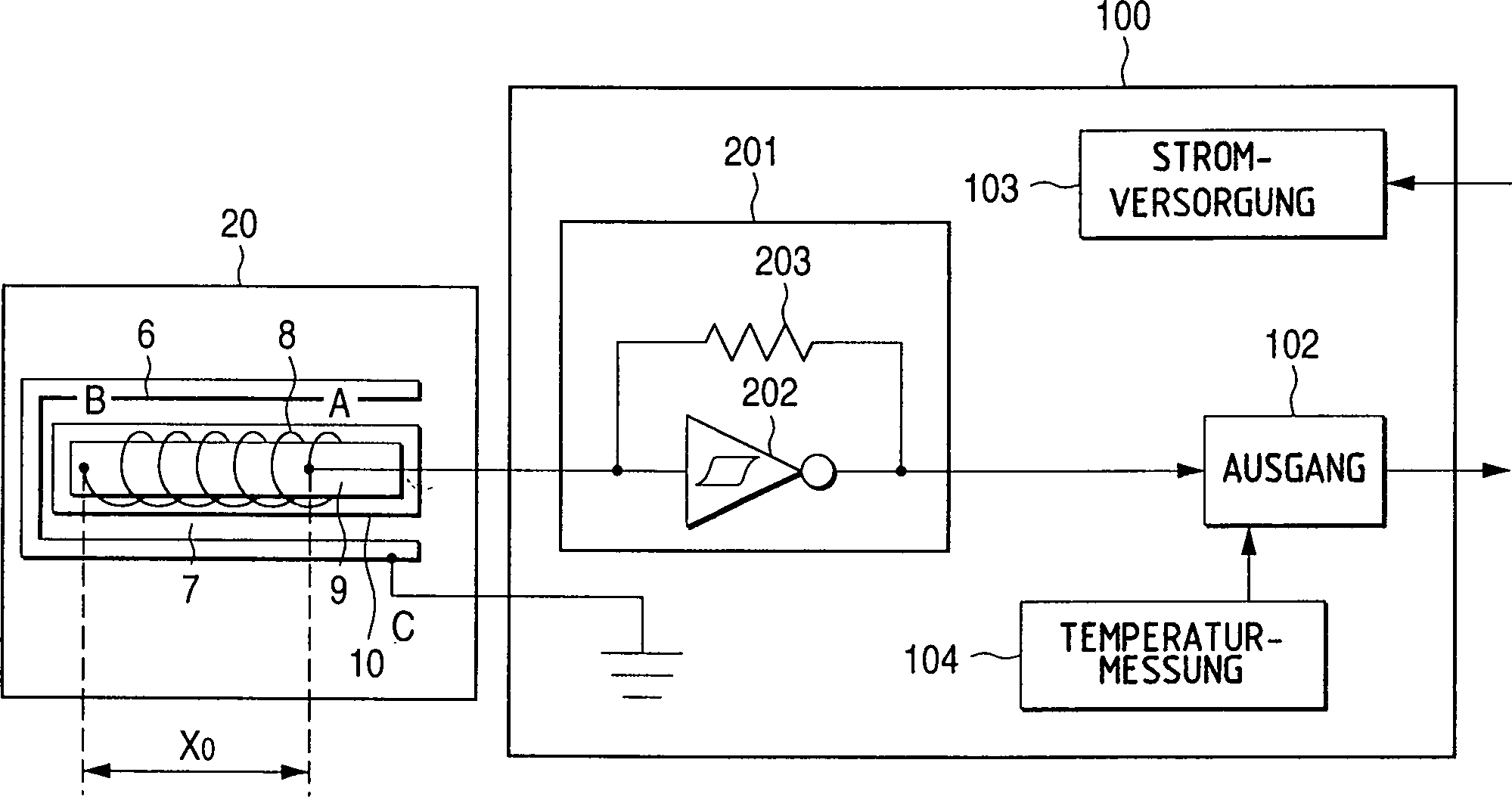
Ein Punkt A ist eine Eingangsklemme der ersten Elektrode 8 für das Impulssignal, und ist an eine Oszillatorschaltung 201 in einer Sensorschaltung 100 angeschlossen. Ein Punkt B ist ein Endpunkt der ersten Elektrode 8 und ist elektrisch geöffnet. Obwohl die erste Elektrode 8 als Spule ausgebildet ist, kann sie daher nicht wie beim Stand der Technik als Induktivität arbeiten, sondern arbeitet nur als eine der Elektroden, welche die Übertragungsleitung bilden. Die Oszillatorschaltung 201 weist einen Schmidt-Inverter 202 und einen Lastwiderstand 203 von 1 KΩ auf. Eine Anschlußklemme des Schmidt-Inverters 202 dient als Impulssignalerzeugungsvorrichtung. Eine Eingangsklemme des Schmidt-Inverters 202 dient als Impulssignalmeßvorrichtung, welche die Spannungswelle ist, nachdem sie über die Übertragungsleitung übertragen wurde. Ein Ausgang des Schmidt-Inverters 202 ist an eine Ausgangsschaltung 201 angeschlossen. Das Bezugszeichen 103 bezeichnet eine Stromversorgungsschaltung 103 zum Liefern einer stabilisierten konstanten Spannung von 5 V an die gesamte Sensorschaltung. Das Bezugszeichen 104 bezeichnet eine Temperaturmeßschaltung 104, die mit einem Thermistor versehen ist, um eine Temperaturkompensation der Flüssigkeit durchzuführen.A point A is an input terminal of the first electrode 8th for the pulse signal, and is connected to an oscillator circuit 201 in a sensor circuit 100 connected. A point B is an end point of the first electrode 8th and is opened electrically. Although the first electrode 8th is designed as a coil, it can therefore not work as an inductor as in the prior art, but only works as one of the electrodes which form the transmission line. The oscillator circuit 201 has a Schmidt inverter 202 and a load resistor 203 from 1 KΩ to. A connection terminal of the Schmidt inverter 202 serves as a pulse signal generating device. An input terminal of the Schmidt inverter 202 serves as a pulse signal measuring device which is the voltage wave after it has been transmitted over the transmission line. An exit of the Schmidt inverter 202 is connected to an output circuit 201 connected. The reference number 103 denotes a power supply circuit 103 for supplying a stabilized constant voltage of 5 V to the entire sensor circuit. The reference number 104 denotes a temperature measuring circuit 104 which is provided with a thermistor to perform temperature compensation of the liquid.

Nunmehr wird nachstehend das Betriebsprinzip der ersten Ausführungsform erläutert.Now the principle of operation is as follows the first embodiment explained.

Wie voranstehend geschildert bildet das Gerät nach dem Stand der Technik eine LC-Parallelresonatorschaltung. Da sich der Kapazitätswert der Resonatorschaltung entsprechend der Dielektrizitätskonstante des Kraftstoffs ändert, kann das Gerät die Dielektrizitätskonstante des Kraftstoffs dadurch messen, daß sich die Resonanzfrequenz entsprechend ändert.As described above forms the device according to the prior art, an LC parallel resonator circuit. There the capacity value the resonator circuit corresponding to the dielectric constant of the Fuel changes, can the device the dielectric constant of the fuel by measuring that the resonance frequency changes accordingly.

Im Gegensatz hierzu arbeitet das in 1 dargestellte Gerät nicht auf der Grundlage eines Resonanzeffekts wie das Gerät beim Stand der Technik, sondern verwendet eine verteilte konstante Schaltung, in welcher Induktivitäten und Kondensatoren mit konstanter linearer Dichte verteilt sind, als Übertragungsleitung. Anders ausgedrückt wird, wenn die Übertragungsleitung, die aus der verteilten konstanten Schaltung besteht, als Signalausbreitungsweg verwendet wird, die Ausbreitungsrate, mit welcher sich das Signal über die Übertragungsleitung ausbreitet, durch die Konstanten der verteilten konstanten Schaltung beeinflußt. 2 zeigt schematisch eine Äquivalenzschaltung der Übertragungsleitung 20 des Meßgeräts für die Dielektrizitätskonstante gemäß 1. Die Übertragungsleitung 20 bildet die verteilte konstante Schaltung, in welcher die Induktivitäten und die Kondensatoren mit konstanter linearer Dichte verteilt angeordnet sind.In contrast, the works in 1 shown device not based on a resonance effect as the device in the prior art, but uses a distributed constant circuit in which inductors and capacitors are distributed with a constant linear density, as a transmission line. In other words, when the transmission line composed of the distributed constant circuit is used as the signal propagation path, the rate of propagation at which the signal propagates over the transmission line is affected by the constants of the distributed constant circuit. 2 shows schematically an equivalent circuit of the transmission line 20 of the dielectric constant meter 1 , The transmission line 20 forms the distributed constant circuit in which the inductors and the capacitors are arranged with a constant linear density.

Der Induktivitätswert der verteilten konstanten Schaltung in 2 wird durch die erste Elektrode 8 festgelegt, und stellt einen bereits bekannten Wert dar. Eine Kapazität der verteilten konstanten Schaltung wird zwischen der ersten Elektrode 8 und der zweiten Elektrode 6 verteilt. Diese Kapazität bildet einen Kondensator, der als Elektroden die erste Elektrode 8 und die zweite Elektrode 6 aufweist. In diesem Fall wird der Alkoholmischkraftstoff als die Meßflüssigkeit zwischen den beiden Elektroden des Kondensators eingefüllt. Der Alkoholmischkraftstoff dient als dielektrische Substanz für den Kondensator. Die Beziehung zwischen der Kapazität und der Dielektrizitätskonstante des Kondensators ist wohlbekannt, nämlich

Figure 00170001
The inductance value of the distributed constant circuit in 2 is through the first electrode 8th fixed, and represents a known value. A capacitance of the distributed constant circuit is between the first electrode 8th and the second electrode 6 distributed. This capacitance forms a capacitor that acts as the first electrode 8th and the second electrode 6 having. In this case, the mixed alcohol fuel is filled in as the measuring liquid between the two electrodes of the capacitor. The mixed alcohol fuel serves as a dielectric substance for the condenser. The relationship between the capacitance and the dielectric constant of the capacitor is well known, namely
Figure 00170001

In Gleichung (2) bezeichnet C die Kapazität, ε die Dielektrizitätskonstante, S die Fläche der Elektrode, und 1 die Entfernung zwischen den Elektroden. Da die Fläche S der Elektrode und die Entfernung 1 zwischen den Elektroden festliegen, wird die Kapazität C allein durch die Dielektrizitätskonstante ε der Meßflüssigkeit geändert.In equation (2), C denotes the capacitance, ε the dielectric constant, S the area of the electrode, and 1 the distance between the electrodes. Since the area S of the electrode and the distance 1 between are fixed to the electrodes, the capacitance C is changed solely by the dielectric constant ε of the measuring liquid.

Daher wird die Konstante der verteilten konstanten Schaltung in der Übertragungsleitung 20 ebenfalls geändert, wenn sich die Dielektrizitätskonstante ε der Meßflüssigkeit ändert, so daß auch die Ausbreitungsrate des Signals geändert wird, welches über die Übertragungsleitung 20 übertragen wird.Therefore, the constant of the distributed constant circuit in the transmission line 20 also changed when the dielectric constant ε of the measuring liquid changes, so that the rate of propagation of the signal which is transmitted via the transmission line is also changed 20 is transmitted.

Dies führt dazu, daß die Dielektrizitätskonstante ε der Meßflüssigkeit gemessen werden kann, wenn die Ausbreitungsrate des Signals gemessen werden kann, welches sich über die Übertragungsleitung 20 ausbreitet. Da die Dielektrizitätskonstante des Alkohols in dem Alkoholmischkraftstoff als Meßflüssigkeit im Vergleich zu jener des Benzins extrem groß ist, wirkt sich in diesem Fall eine Änderung der Alkoholkonzentration deutlich als Änderung der Dielektrizitätskonstanten des Alkoholmischkraftstoffs aus. Aus diesem Grund kann die Alkoholkonzentration ebenfalls festgestellt werden, wenn die Dielektrizitätskonstante des Alkoholmischkraftstoffs festgestellt wird, wodurch diese Information für die Brennkraftmaschinensteuerung eingesetzt werden kann.This leads to the fact that the dielectric constant ε of the measuring liquid can be measured if the propagation rate of the signal can be measured, which is transmitted over the transmission line 20 spreads. In this case, since the dielectric constant of the alcohol in the alcohol mixed fuel as the measuring liquid is extremely large compared to that of the gasoline, a change in the alcohol concentration has a marked effect as a change in the dielectric constant of the alcohol mixed fuel. For this reason, the alcohol concentration can also be determined when the dielectric constant of the mixed alcohol fuel is determined, whereby this information can be used for the engine control.

Als nächstes wird nachstehend die erste Ausführungsform genauer erläutert.Next, the first embodiment explained in more detail.

In 2 ist, da die erste Elektrode 8 so gewickelt ist, daß die längliche zylindrische Spule entlang der Richtung der X-Achse ausgebildet wird, die Induktivität über die Übertragungsleitung 20 entlang der Richtung der X-Achse verteilt. Da die erste Elektrode 8 und die zweite Elektrode 6 einander gegenüberliegen, so daß dazwischen die Meßflüssigkeit angeordnet ist, ist gleichzeitig die Kapazität über die Übertragungsleitung 20 entsprechend der Dielektrizitätskonstanten der Meßflüssigkeit entlang der Richtung der X-Achse verteilt.In 2 is because the first electrode 8th is wound so that the elongated cylindrical coil is formed along the direction of the X axis, the inductance through the transmission line 20 distributed along the direction of the X axis. Because the first electrode 8th and the second electrode 6 opposite each other, so that the measuring liquid is arranged between them, is at the same time the capacity via the transmission line 20 distributed according to the dielectric constant of the measuring liquid along the direction of the X axis.

Es ist wesentlich, daß die erste Elektrode 8 in Form einer zylindrischen Spule gewickelt ist. Wenn das Längenverhältnis (Länge/Durchmesser) der ersten Elektrode klein ist, kann die Übertragungsleitung 20 nicht die verteilte konstante Schaltung ausbilden. Dies führt dazu, daß wie beim Stand der Technik die Übertragungsleitung 20 als Äquivalenzschaltung dargestellt werden muß, bei welcher die Induktivität L0 und die Kapazität C0, die beide eine punktförmige Konstante bilden, parallel geschaltet sind. Zusätzlich wirkt sich, daß der Endpunkt der ersten Elektrode 8 geöffnet ist, die Induktivität nicht aus, und arbeitet die Übertragungsleitung 20 als reiner Kondensator. Daher kann der gewünschte Betrieb der Übertragungsleitung 20 nicht erzielt werden. Jedoch kann, wie dies durch die Äquivalenzschaltung in 2 dargestellt ist, die verteilte konstante Schaltung, bei welcher die Induktivität und die Kapazität mit konstanter linearer Dichte verteilt sind, dadurch ausgebildet werden, daß die erste Elektrode 8 als zylindrische Spule ausgebildet wird. Daher beträgt als Ergebnis unserer Versuche das gewünschte Längenverhältnis mehr als 4 oder 5.It is essential that the first electrode 8th is wound in the form of a cylindrical coil. If the aspect ratio (length / diameter) of the first electrode is small, the transmission line can 20 do not form the distributed constant circuit. As a result, as in the prior art, the transmission line 20 must be represented as an equivalent circuit in which the inductance L0 and the capacitance C0, both of which form a punctiform constant, are connected in parallel. In addition, the end point of the first electrode acts 8th is open, the inductance is not off, and the transmission line is working 20 as a pure capacitor. Therefore, the desired operation of the transmission line 20 cannot be achieved. However, as indicated by the equivalent circuit in 2 is shown, the distributed constant circuit, in which the inductance and the capacitance are distributed with constant linear density, are formed in that the first electrode 8th is designed as a cylindrical coil. Therefore, as a result of our tests, the desired aspect ratio is more than 4 or 5.

Anders ausgedrückt stellt die in 2 dargestellte Äquivalenzschaltung eine Übertragungsleitung dar, die einer Äquivalenzschaltung elektronischer Bauteile zur Verzögerung des Impulssignals entspricht, also einer Verzögerungsleitung. Eine derartige Äquivalenzschaltung kann die Welle sich mit vorbestimmter Ausbreitungsrate ausbreiten lassen.In other words, the in 2 Equivalence circuit shown represents a transmission line which corresponds to an equivalent circuit of electronic components for delaying the pulse signal, that is, a delay line. Such an equivalent circuit can allow the wave to propagate at a predetermined propagation rate.

Als nächstes werden verschiedene Werte der verteilten konstanten Schaltung erläutert.Next, different ones Values of the distributed constant circuit explained.

Zur Vereinfachung wird angenommen, daß der elektrische Widerstand der ersten Elektrode 8 gleich 0 (Null) ist, daß die zylindrische Form eine ausreichende Länge hat, um die verteilte konstante Schaltung auszubilden, daß die Induktivitätslineardichte pro Längeneinheit in Richtung der X-Achse gleich ρ (H/m) beträgt, die Kapazitätslineardichte gleich σ (F/m), die Lineardichte der Ladung, die pro Längeneinheit angesammelt wird, gleich q (C/m) ist, der Strom gleich I (A), die Spannung gleich V (V), eine Position gleich x (m) ist, und die Zeit t (Sekunden) ist, dann ergibt sich folgende Gleichung (3)

Figure 00200001
For simplification, it is assumed that the electrical resistance of the first electrode 8th is equal to 0 (zero), that the cylindrical shape is of sufficient length to form the distributed constant circuit, that the inductance linear density per unit length in the direction of the X-axis is equal to ρ (H / m), the capacitance linear density is equal to σ (F / m), the linear density of the charge accumulated per unit length is q (C / m), the current is I (A), the voltage is V (V), a position is x (m), and the Time t (seconds), the following equation (3) results
Figure 00200001

Dies ergibt sich aus der Kontinuitätsbedingung. Weiterhin ergibt sich aus der Kapazitätsgleichung die Gleichung (4)

Figure 00200002
This results from the continuity condition. The equation (4) also results from the capacitance equation
Figure 00200002

Weiterhin ergibt sich aus der Induktivitätsgleichung die Gleichung (5)

Figure 00200003
Furthermore, equation (5) results from the inductance equation
Figure 00200003

Eliminiert man q und I unter Verwendung der Gleichungen (3) bis (5), dann ergibt sich Gleichung (6)If q and I are eliminated using the equations ( 3 ) to (5), then equation (6) results

Figure 00210001
Figure 00210001

Da Gleichung (6) eine Wellengleichung der Spannungswelle darstellt, sieht man, daß sich die Spannungswelle über diese Übertragungsleitung mit einer Ausbreitungsrate U ausbreiten kann, die durch Gleichung (7) ausgedrückt wird.Since equation (6) is a wave equation represents the voltage wave, you can see that the voltage wave over this transmission line can spread with a propagation rate U expressed becomes.

Figure 00210002
Figure 00210002

Nunmehr wird angenommen, daß die Induktivität der gesamten Übertragungsleitung gleich L0 ist, und die Kapazität der gesamten Übertragungsleitung gleich C0, so ergibt sich ein Zeitraum Tp, der erforderlich ist, damit die Impulswelle über die Übertragungsleitung gelangt, folgendermaßen

Figure 00210003
da L0 = ρ x X0, C0 = σ x X0 ist .Now, assuming that the inductance of the entire transmission line is L0 and the capacitance of the entire transmission line is C0, the time period Tp required for the pulse wave to pass through the transmission line is as follows
Figure 00210003
since L0 = ρ x X0, C0 = σ x X0.

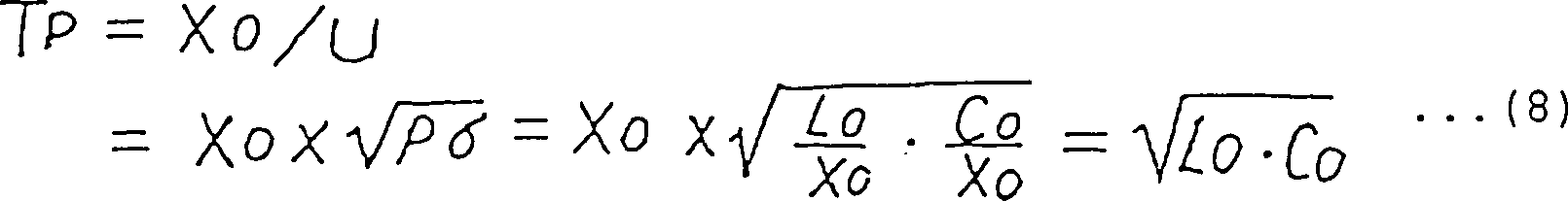
Die charakteristische Impedanz Z0 läßt sich folgendermaßen ausdrücken

Figure 00210004
The characteristic impedance Z0 can be expressed as follows
Figure 00210004

Bei dieser Ausführungsform ergeben sich, wenn Ethanol in die Kammer 7 eingefüllt wird, folgende Meßwerte.In this embodiment, when ethanol enters the chamber 7 is filled in, the following measured values.

X0 = 32,5 mm, L0 = 29,5 μH, C0 = 25,2 pFX0 = 32.5 mm, L0 = 29.5 μH, C0 = 25.2 pF

Wenn die Gleichungen (7) bis (9) unter Verwendung dieser Werte berechnet werden, ergeben sich folgende Werte

Figure 00220001
When equations (7) to (9) are calculated using these values, the following values result
Figure 00220001

Als nächstes wird der Betriebsablauf bei der ersten Ausführungsform der vorliegenden Erfindung nachstehend unter Bezugnahme auf die 3A bis 3D erläutert. Die 3A bis 3D sind Diagramme, die das Verhalten der Spannungswelle bei der Übertragung über die Übertragungsleitung 20 darstellen.Next, the operation in the first embodiment of the present invention will be described below with reference to FIG 3A to 3D explained. The 3A to 3D are diagrams showing the behavior of the voltage wave during transmission over the transmission line 20 represent.

Das Meßgerät für die Dielektrizitätskonstante gemäß der ersten Ausführungsform arbeitet in der folgenden Sequenz.The measuring device for the dielectric constant according to the first embodiment works in the following sequence.

Wenn die Spannung an einem Punkt A kleiner ist als eine untere Schwellenspannung des Schmidt-Inverters 202 zum Zeitpunkt t = 0, so steigt das Ausgangssignal des Schmidt-Inverters 202 von 0 V auf die Versorgungsspannung 5V an, nachdem eine Verzögerungszeit Td von etwa 3,5 ns für die Ausbreitung bei dem Schmidt-Inverter 202 abgelaufen ist.If the voltage at point A is less than a lower threshold voltage of the Schmidt inverter 202 at time t = 0, the output signal of the Schmidt inverter rises 202 from 0 V to the supply voltage 5V after a delay time Td of about 3.5 ns for propagation at the Schmidt inverter 202 has expired.

Der Schmidt-Inverter 202 bildet eine Impulsspannungserzeugungsvorrichtung.The Schmidt inverter 202 forms a pulse voltage generating device.

Da die charakteristische Impedanz Z0 der Übertragungsleitung etwa 1 KΩ beträgt, wird die Versorgungsspannung durch den Lastwiderstand 203 mit 1 KΩ und die charakteristische Impedanz Z0 der Übertragungsleitung 20 geteilt, so daß sich etwa 2,5 V als Spannung am Punkt A ergeben. Wie später noch genauer erläutert wird, wird die Spannung an dem Punkt A auf diesen Wert gehalten, bis die reflektierte Welle zum Punkt A zurückkehrt. Der Eingangsstrom, der in die Übertragungsleitung 20 fließt, wird etwa 2,5 mA, was sich durch Teilen der Spannung am Punkt A durch die charakteristische Impedanz ergibt. Da der Eingang des Schmidt-Inverters 202 nicht eine obere Schwellenspannung überschreitet, wird zu diesem Zeitpunkt das Ausgangssignal des Schmidt-Inverters 202 auf 5 V gehalten.Since the characteristic impedance Z0 of the transmission line is approximately 1 KΩ, the supply voltage becomes due to the load resistance 203 with 1 KΩ and the characteristic impedance Z0 of the transmission line 20 divided so that there is about 2.5 V as a voltage at point A. As will be explained in more detail later, the voltage at point A is held at this value until the reflected wave returns to point A. The input current that is in the transmission line 20 flows, becomes about 2.5 mA, which results from dividing the voltage at point A by the characteristic impedance. Since the entrance of the Schmidt inverter 202 does not exceed an upper threshold voltage, the output signal of the Schmidt inverter at this time 202 kept at 5 V.

Wie in 3A gezeigt ist, ist eine Stufenspannungswelle ein Impulssignal, welches eine Amplitude von 2,5 V aufweist. Ein derartiges Impulssignal breitet sich als einfallende Spannungswelle vom Punkt A zum Punkt B mit einer Rate von U = 1190 km/sec aus. Zu diesem Zeitpunkt weisen die rechte Seite bzw. die linke Seite der Vorderkante der Stufenspannungswelle den gleichmäßigen Wert von 2,5 V bzw. 0 V auf. Im Idealfall kann sich die Stufenspannungswelle ausbreiten, während ihre rechteckige Vorderkante auf einem Winkel von 90 Grad gehalten wird. Tatsächlich ist die Vorderkante der Stufenspannungswelle entsprechend der Ausbreitung geneigt ausgebildet, wie in 3A dargestellt.As in 3A is shown, a step voltage wave is a pulse signal having an amplitude of 2.5 V. Such a pulse signal propagates as an incident voltage wave from point A to point B at a rate of U = 1190 km / sec. At this time, the right side and the left side of the front edge of the step voltage wave have the uniform value of 2.5 V and 0 V, respectively. Ideally, the step voltage wave can propagate while keeping its rectangular leading edge at an angle of 90 degrees. In fact, the leading edge of the step voltage wave is inclined according to the propagation, as in FIG 3A shown.

Nachdem seit Erzeugung der Stufenspannung ein Zeitraum Tp vergangen ist, gelangt die Vorderkante der Stufenspannungswelle zum Endpunkt B an einem Zeitpunkt t1 (= Td + Tp = 3,5 + 27 = 30,5 ns). Eine derartige Spannungswelle hat solche Eigenschaften, daß sich ihre Ausbreitung fortsetzt, wenn die charakteristische Impedanz der Übertragungsleitung einen im wesentlichen identischen Wert aufweist, jedoch dort reflektiert wird, wenn die charakteristische Impedanz der Übertragungsleitung an einem bestimmten Ort ansteigt. Da der Punkt B ein offenes Ende darstellt, entspricht er einer Impedanz von unendlich. Daher wird, wie in 3B gezeigt, an dem Punkt B die reflektierte Welle von 2,5 V erzeugt, und breitet sich dann vom Punkt B nach rechts aus. Dies führt dazu, daß die Spannung gleichmäßig den Wert von 5 V in einem Bereich annimmt, in welchem die reflektierte Welle und die einfallende Welle einander überlagert werden, also auf der linken Seite der Vorderkante der reflektierten Welle, wogegen die Spannung gleichmäßig den Wert von 2,5 V auf der rechten Seite der Vorderkante annimmt. Die Vorderkante der Spannungswelle ist weiter geneigt.After a period Tp has passed since the step voltage was generated, the front edge of the step voltage wave reaches the end point B at a time t1 (= Td + Tp = 3.5 + 27 = 30.5 ns). Such a voltage wave has such properties that its propagation continues when the characteristic impedance of the transmission line has a substantially identical value, but is reflected there when the characteristic impedance of the transmission line increases at a particular location. Since point B represents an open end, it corresponds to an impedance of infinity. Therefore, as in 3B shown at point B generates the reflected wave of 2.5 V, and then spreads from point B to the right. As a result, the voltage takes the value of 5 V evenly in a range in which the reflected wave and the incident wave are superimposed on each other, that is, on the left side of the front edge of the reflected wave, whereas the voltage evenly takes the value of 2 , 5 V on the right side of the leading edge. The front edge of the voltage wave is further inclined.

Die Vorderkante der reflektierten Welle erreicht den Punkt A zu einem Zeitpunkt t2 (= Td + 2Tp = 3,5 x 25 = 57,7 ns). Zu diesem Zeitpunkt sinkt, da die Spannung am Punkt A den Wert von 5 V annimmt, so daß die obere Schwellenspannung des Schmidt-Inverters 202 überschritten wird, die Ausgangsspannung des Schmidt-Inverters 202 von 5 V auf 0 V ab, zu einem Zeitpunkt t3 (= 2Td + 2Tp = 2 x 3,5 + 2 x 27 = 61 ns), der durch die Verzögerungszeit Td für die Ausbreitung beim Schmidt-Inverter 202 verzögert ist, wodurch der Einfall der Spannungswelle beendet ist. Der Schmidt-Inverter 202 bildet eine Impulssignalmeßvorrichtung. Es wird deutlich, daß der Schmidt-Inverter 202 weiter die einfallende Welle mit einer Spannung von 2,5 V ausgibt, die sich vom Punkt A nach links hin ausbreitet, bis zu diesem Zeitpunkt für Td + 2Tp = 57,5 ns.The leading edge of the reflected wave reaches point A at a time t2 (= Td + 2Tp = 3.5 x 25 = 57.7 ns). At this time, the voltage at point A decreases to 5 V, so that the upper threshold voltage of the Schmidt inverter 202 is exceeded, the output voltage of the Schmidt inverter 202 from 5 V to 0 V at a time t3 (= 2Td + 2Tp = 2 x 3.5 + 2 x 27 = 61 ns), which is due to the delay time Td for the propagation at the Schmidt inverter 202 is delayed, whereby the incidence of the voltage wave is ended. The Schmidt inverter 202 forms a pulse signal measuring device. It is clear that the Schmidt inverter 202 continues to output the incident wave with a voltage of 2.5 V, which spreads from point A to the left, until then for Td + 2Tp = 57.5 ns.

Da ein Widerstand von 1 KΩ als Lastwiderstand 203 ausgewählt ist, kann in Bezug auf die reflektierte Welle, unter Berücksichtigung von 1080 Ω als charakteristischer Impedanz Z0 die Übertragungsleitung 20 die Impedanzanpassung im wesentlichen aufrechterhalten werden. Daher tritt selten eine derartige Situation auf, daß dann, wenn sie den Punkt A erreicht, die reflektierte Welle eine erneute Reflexion am Punkt A hervorruft.Since a resistance of 1 KΩ as a load resistance 203 is selected, with regard to the reflected wave, taking into account 1080 Ω as the characteristic impedance Z0, the transmission line 20 can essentially maintain the impedance matching. Therefore, such a situation rarely occurs that when it reaches point A, the reflected wave causes reflection at point A again.

Wenn sich das Ausgangssignal des Schmidt-Inverters 202 von 5 V auf 0 V ändert, um so die Stufenspannungswelle zu beenden, so breitet sich die Hinterkante der einfallenden Welle nach links aus, wie in 3C gezeigt ist. Zu diesem Zeitpunkt nimmt die Spannung gleichmäßig den Wert von 5 V an der linken Seite der Hinterkante der einfallenden Welle an, wogegen die Spannung gleichmäßig den Wert von 2,5 V auf der rechten Seite der Hinterkante annimmt, da nur die reflektierte Welle übrigbleibt. Wie die Vorderkante der Stufenspannungswelle ist auch die Hinterkante in Bezug auf die Ausbreitung geneigt angeordnet.If the output signal of the Schmidt inverter 202 changes from 5 V to 0 V so as to end the step voltage wave, the trailing edge of the incident wave spreads to the left, as in 3C is shown. At this time, the voltage smoothly takes the value of 5 V on the left side of the trailing edge of the incident wave, whereas the voltage smoothly takes the value of 2.5 V on the right side of the trailing edge, since only the reflected wave remains. Like the leading edge of the step voltage wave, the trailing edge is also inclined with respect to the propagation.

Nachdem die Hinterkante der Eingangswelle am Punkt B reflektiert wurde, breitet sie sich nach rechts aus, wie in 3D gezeigt ist.After the trailing edge of the input wave is reflected at point B, it spreads to the right, as in 3D is shown.

Wenn die Hinterkante der Eingangswelle reflektiert wird, und dann zum Punkt A zum Zeitpunkt t4 zurückkehrt (= 2Td + 4Tp = 2 x 3,5 + 4 x 27 = 115 ns), wird die Spannung der gesamten Übertragungsleitung einschließlich des Punktes A gleichmäßig zu 0 V.If the trailing edge of the input shaft is reflected, and then returns to point A at time t4 (= 2Td + 4Tp = 2 x 3.5 + 4 x 27 = 115 ns), the voltage of the entire transmission line including the Point A evenly to 0 V.

Da die Spannung am Punkt A niedriger ist als die untere Schwellenspannung des Schmidt-Inverters 202, wenn sie den Wert von 0 V annimmt, ändert sich die Ausgangsspannung des Schmidt-Inverters 202 von 0 V auf 5 V, nach der Verzögerungszeit Td (3,5 ns) für die Ausbreitung bei dem Schmidt-Inverter 202. Danach werden die voranstehenden Operationen wiederholt.Since the voltage at point A is lower than the lower threshold voltage of the Schmidt inverter 202 if it takes the value of 0 V, the output voltage of the Schmidt inverter changes 202 from 0 V to 5 V, after the delay time Td (3.5 ns) for the propagation in the Schmidt inverter 202 , After that, the above operations are repeated.

Es wird darauf hingewiesen, daß dann, wenn die Dielektrizitätskonstante des Alkoholmischkraftstoffs groß ist, infolge einer hohen Alkoholkonzentration, die Ausbreitungszeit Tp des Impulssignals über die Übertragungsleitung lang wird, da die Kapazität C0 erhöht wird, wie berechnet durch Gleichung (8).It should be noted that if the dielectric constant the mixed alcohol fuel is large, due to a high alcohol concentration, the propagation time Tp of the pulse signal the transmission line becomes long because of the capacity C0 increased is as calculated by equation (8).

Wie voranstehend wird bei der ersten Ausführungsform der folgende Zeitraum T wiederholt, und ergibt sich die Schwingungsfrequenz F folgendermaßen.As above, the first embodiment the following period T repeats, and the oscillation frequency results F as follows.

Figure 00260001
Figure 00260001

Hierbei ist die Schwingungsfrequenz F ein Wert, welcher der Ausbreitungsgeschwindigkeit zugeordnet ist, nämlich der Geschwindigkeit der Signalausbreitung über die verteilte konstante Schaltung. Wie voranstehend erwähnt bezeichnet, da es sich bei der ersten Ausführungsform um die verteilte konstante Schaltung handelt, die Schwingungsfrequenz F nicht die Resonanzfrequenz beim Stand der Technik. Insbesondere besteht das Wesen des Resonanzeffektes darin, daß keine Signalverzögerung auftritt, und offensichtlich wird bei der ersten Ausführungsform kein Resonanzeffekt hervorgerufen, da die Verzögerung von 2Td vorhanden ist, wie aus Gleichung (10) hervorgeht.Here is the vibration frequency F is a value which is assigned to the speed of propagation, namely the speed of signal propagation over the distributed constant Circuit. As mentioned above referred to, since the first embodiment is the distributed one constant circuit, the oscillation frequency F is not Resonance frequency in the prior art. In particular, there is Essence of the resonance effect in that there is no signal delay, and obviously there is no resonance effect in the first embodiment caused because of the delay of 2Td is present as shown in equation (10).

Diese Verzögerung von 2Td tritt infolge der Ausbreitungsverzögerung des Schmidt-Inverters 202 auf. Der Schmidt-Inverter 202 bildet bei der ersten Ausführungsform eine Resonanzverhinderungsvorrichtung.This 2Td delay occurs due to the propagation delay of the Schmidt inverter 202 on. The Schmidt inverter 202 forms a resonance preventing device in the first embodiment.

4 zeigt eine gemessene Signalform der Spannungswelle am Punkt A als Eingangsklemme der Übertragungsleitung des Meßgeräts für die Dielektrizitätskonstante einer Flüssigkeit gemäß der ersten Ausführungsform. Bei dieser gemessenen Signalform tritt eine Signalform auf, welche die voranstehende Erläuterung unterstützt, abgesehen davon, daß die Schwingung bei einer Frequenz von 8,2 MHz auftritt, was geringfügig niedriger ist als der Wert, der durch die voranstehende Berechnung berechnet wird, und daß die Neigung der Signalform geringfügig größer ist. 4 shows a measured waveform of the voltage wave at point A as an input terminal of the transmission line of the measuring device for the dielectric constant of a liquid according to the first embodiment. With this measured waveform, a waveform occurs which supports the above explanation, except that the vibration occurs at a frequency of 8.2 MHz, which is slightly lower than the value calculated by the above calculation, and that Slope of the waveform is slightly larger.

Wenn der Kraftstoff in die Kammer 7 eingefüllt wird, ändert sich die Induktivitätslineardichte ρ selten, jedoch ändert sich die Kapazitätslineardichte σ entsprechend der Dielektrizitätskonstanten des Alkoholmischkraftstoffs. Zu diesem Zeitpunkt ändert sich die Oszillatorfrequenz F gemäß Gleichung (10). Daher können die Spannungswellenausbreitungsrate über die Übertragungsleitung, die Dielektrizitätskonstante des Kraftstoffs, und das Alkoholmischverhältnis erfaßt werden, durch Messung der Schwingungsfrequenz F, so daß eine entsprechende Brennkraftmaschinensteuerung durchgeführt werden kann.When the fuel in the chamber 7 is filled, the inductance linear density ρ rarely changes, but the capacitance linear density σ changes according to the dielectric constant of the mixed alcohol fuel. At this time, the oscillator frequency F changes according to equation (10). Therefore, the voltage wave propagation rate through the transmission line, the dielectric constant of the fuel, and the alcohol mixture ratio can be detected by measuring the vibration frequency F, so that an appropriate engine control can be performed.

Im einzelnen wird in 1 die Schwingungsfrequenz F, die von der Oszillatorschaltung 201 gemessen wird, der Ausgangsschaltung 102 zugeführt, und wird dann in dieser in einem vorbestimmten Verhältnis geteilt. Zusätzlich zur Schwingungsfrequenz F wird auch Temperaturinformation in Bezug auf die gemessene Flüssigkeit von der Temperaturmeßschaltung 104 an die Ausgangsschaltung geschickt.In detail, in 1 the oscillation frequency F by the oscillator circuit 201 is measured, the output circuit 102 supplied, and is then divided in this in a predetermined ratio. In addition to the oscillation frequency F, temperature information relating to the measured liquid is also provided by the temperature measuring circuit 104 sent to the output circuit.

Die Beziehung zwischen der Alkoholkonzentration in dem Alkoholmischkraftstoff und der Schwingungsfrequenz F ist nicht immer konstant, sondern weist eine Temperaturabhängigkeit auf. Daher teilt die Ausgangsschaltung 102 die Schwingungsfrequenz F auf, und korrigiert die Ausgangsfrequenz auf der Grundlage der Temperatur der Meßflüssigkeit, und gibt diese Werte dann zu einer Brennkraftmaschinensteuervorrichtung (nicht dargestellt) aus, die aus einem Mikrocomputer oder dergleichen besteht.The relationship between the alcohol concentration in the mixed alcohol fuel and the vibration frequency F is not always constant, but has a temperature dependency. Therefore, the output circuit shares 102 the oscillation frequency F, and corrects the output frequency based on the temperature of the measuring liquid, and then outputs these values to an engine control device (not shown) consisting of a microcomputer or the like.

Die Brennkraftmaschinensteuervorrichtung vergleicht die geteilte Schwingungsfrequenz, die von der Ausgangsschaltung 102 erhalten wird, mit der Frequenz, die vorher experimentell festgestellt wurde, auf der Grundlage der Alkoholkonzentration, berechnet die gewünschte Information wie beispielsweise die erfaßte Alkoholkonzentration, die Dielektrizitätskonstante und dergleichen in dem Alkoholmischkraftstoff, und setzt dann derartige Information bei der Luft/Kraftstoffverhältnisregelung, der Zündzeitpunktregelung und dergleichen ein.The engine control device compares the divided oscillation frequency generated by the output circuit 102 is obtained at the frequency previously determined experimentally based on the alcohol concentration, calculates the desired information such as the detected alcohol concentration, dielectric constant and the like in the mixed alcohol fuel, and then sets such information in the air-fuel ratio control, the ignition timing control and the like.

Bei der ersten Ausführungsform ist die Ausgangsschaltung so ausgelegt, daß sie Information in Bezug auf die Schwingungsfrequenz ausgibt, die entsprechend der Temperatur der Meßflüssigkeit korrigiert wurde. Allerdings kann die Ausgangsschaltung 102 auch eine Schaltung zur Berechnung der Dielektrizitätskonstanten auf der Grundlage der Schwingungsfrequenz aufweisen, oder eine Schaltung zur Berechnung der Alkoholkonzentration.In the first embodiment, the output circuit is designed to output information related to the oscillation frequency, which has been corrected according to the temperature of the measuring liquid. However, the output circuit 102 also have a circuit for calculating the dielectric constant based on the oscillation frequency, or a circuit for calculating the alcohol concentration.

AUSFÜHRUNGSFORM 2EMBODIMENT 2

Bei der ersten Ausführungsform ist der Wert des Lastwiderstands 203 so gewählt, daß die Impedanzanpassung zwischen dem Lastwiderstand 203 und der charakteristischen Impedanz Z0 der Übertragungsleitung 20 aufrechterhalten werden kann, so daß keine erneute Reflexion hervorgerufen wird, wenn das Impulssignal, welches sich über die Übertragungsleitung ausgebreitet hat, in die Impulserfassungsschaltung hineingelangt.In the first embodiment, the value of the load resistance 203 chosen so that the impedance matching between the load resistance 203 and the characteristic impedance Z0 of the transmission line 20 can be maintained so that no re-reflection is caused when the pulse signal that has propagated over the transmission line enters the pulse detection circuit.

Es ist erwünscht, daß der Wert dieses Lastwiderstands so eingestellt wird, daß er nicht von der Hälfte der charakteristischen Impedanz Z0 der Übertragungsleitung 20 abweicht.It is desirable that the value of this load resistance be set so that it is not half of the characteristic impedance Z0 of the transmission line 20 differs.

Da sich jedoch die charakteristische Impedanz Z0 der Übertragungsleitung 20 ändert, wie durch Gleichung (9) angegeben ist, entsprechend der Kapazitätslineardichte σ, also der Dielektrizitätskonstanten der Meßflüssigkeit in der Kammer 7, ist es grundsätzlich unmöglich, ständig perfekt die Impedanzanpassung zwischen der charakteristischen Impedanz Z0 und dem Lastwiderstand 203 aufrechtzuerhalten.However, since the characteristic impedance Z0 of the transmission line 20 changes, as indicated by equation (9), in accordance with the capacitance linear density σ, that is, the dielectric constant of the measuring liquid in the chamber 7 , it is fundamentally impossible to constantly perfect the impedance matching between the characteristic impedance Z0 and the load resistance 203 maintain.

Wenn sich jedoch die Dielektrizitätskonstante der Meßflüssigkeit in dem Meßbereich ändert, tritt kein wesentlicher Einfluß auf, wenn die charakteristische Impedanz Z0 der Übertragungsleitung 20 so eingestellt ist, daß sie nicht von der Hälfte des Lastwiderstands 203 abweicht.If, however, the dielectric constant of the measuring liquid changes in the measuring range, there is no significant influence if the characteristic impedance Z0 of the transmission line 20 is set so that it is not half of the load resistance 203 differs.

Bei der zweiten Ausführungsform ist eine Kanalbreite für die Meßflüssigkeit, die zwischen der ersten Elektrode 8 und der zweiten Elektrode 6 fließt, so beschränkt, daß sie enger ist, durch Erhöhung der Dicke einer Isolierbeschichtung 10. Die Isolierbeschichtung 10 dient dazu, eine Kanalbreitenbegrenzungsvorrichtung bereitzustellen, zur Einschränkung der Kanalbreite für die Meßflüssigkeit.In the second embodiment, a channel width for the measuring liquid is between the first electrode 8th and the second electrode 6 flows, restricted to be narrower, by increasing the thickness of an insulating coating 10 , The insulating coating 10 serves to provide a channel width limiting device for restricting the channel width for the measuring liquid.

Hierbei wirken die Isolierbeschichtung 10 und die Meßflüssigkeit als die dielektrische Substanz zwischen der ersten Elektrode 8 und der zweiten Elektrode 6. In diesem Fall ist die Kapazität zwischen beiden Elektroden äquivalent zu einer Reihenschaltung einer Kapazität 1 unter Verwendung der Isolierbeschichtung 10 als dielektrischer Substanz und einer Kapazität 2 unter Verwendung der Meßflüssigkeit als dielektrischer Substanz. Die Kapazität ergibt sich folgendermaßen.This is where the insulating coating works 10 and the measuring liquid as the dielectric substance between the first electrode 8th and the second electrode 6 , In this case, the capacitance between the two electrodes is equivalent to a series connection of a capacitance 1 using the insulating coating 10 as a dielectric substance and a capacitance 2 using the measuring liquid as a dielectric substance. The capacity is as follows.

Figure 00300001
Figure 00300001

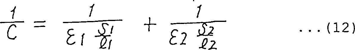
Hierbei betrifft der erste Term auf der rechten Seite die Kapazität 1 unter Verwendung der Isolierbeschichtung 10 als dielektrischer Substanz, und der zweite Term der rechten Seite die Kapazität 2 unter Verwendung der Meßflüssigkeit als dielektrischer Substanz.The first term on the right concerns capacity 1 using the insulating coating 10 as a dielectric substance, and the second term on the right is the capacitance 2 using the measuring liquid as a dielectric substance.

Die Kapazität 1 bei der voranstehenden Gleichung (12) ist ein fester Wert. Wenn der Raum zwischen beiden Elektroden beinahe vollständig durch die Dicke der Isolierbeschichtung 10 eingenommen wird, wird der Wert der Kapazität, der zwischen beiden Elektroden hervorgerufen wird, kaum beeinflußt, selbst wenn sich der Wert der Kapazität 1 des ersten Terms der rechten Seite wesentlich ändert, infolge einer Änderung der Dielektrizitätskonstanten der Meßflüssigkeit.The capacity 1 in the above equation (12) is a fixed value. If the space between the two electrodes is almost completely covered by the thickness of the insulating coating 10 is taken, the value of the capacitance caused between the two electrodes is hardly affected even if the value of the capacitance changes 1 of the first term on the right side changes significantly as a result of a change in the dielectric constant of the measuring liquid.

Daher kann eine Änderung der Kapazität, die zwischen beiden Elektroden vorhanden ist, und durch die Änderung der Dielektrizitätskonstanten der Meßflüssigkeit hervorgerufen wird, dadurch unterdrückt werden, daß die Dicke der Isolierbeschichtung erhöht wird.Therefore, a change in capacity between both electrodes are present, and by changing the dielectric constant the measuring liquid is caused to be suppressed by the fact that the thickness the insulation coating increased becomes.

Daher kann eine Änderung der charakteristischen Impedanz dadurch verringert werden, daß die Kanalbreite für die Meßflüssigkeit eingeschränkt wird, und kann eine erneute Reflexion des Impulssignals an der Impulsmeßvorrichtung unterdrückt werden, nachdem sich das Impulssignal über die Übertragungsleitung 20 ausgebreitet hat.Therefore, a change in the characteristic impedance can be reduced by restricting the channel width for the measuring liquid, and re-reflection of the pulse signal on the pulse measuring device can be suppressed after the pulse signal is transmitted through the transmission line 20 has spread.

Bei der zweiten Ausführungsform wird die Kanalbreite für die Meßflüssigkeit dadurch eingeschränkt, daß die Dicke der Isolierbeschichtung 10 geändert wird. Diese Einschränkung ist hierauf nicht begrenzt, und es kann jede geeignete Vorrichtung eingesetzt werden, die dazu führt, daß die Kanalbreite für die Meßflüssigkeit entlang der Entfernung zwischen beiden Elektroden eingeschränkt wird.In the second embodiment, the channel width for the measuring liquid is restricted in that the thickness of the insulating coating 10 will be changed. This limitation is not limited to this, and any suitable device can be used which results in the channel width for the measuring liquid being restricted along the distance between the two electrodes.

AUSFÜHRUNGSFORM 3EMBODIMENT 3

5 ist ein Schaltbild einer Oszillatorschaltung eines Meßgeräts für die Dielektrizitätskonstante einer Flüssigkeit gemäß der dritten Ausführungsform der vorliegenden Erfindung. Bei dem Meßgerät für die Dielektrizitätskonstante gemäß der ersten Ausführungsform tritt, wie durch die in 4 dargestellte Meßsignalform angedeutet, üblicherweise ein normaler Betrieb auf, jedoch gibt es den Fall, daß eine quasi-stabile Schwingung einer andere Frequenz hervorgerufen wird, die höher ist als die voranstehend angegebene Fundamentalfrequenz, nämlich wenn starkes Rauschen einwirkt. Dies liegt daran, daß die Ausgangsspannungssignalform des Schmidt-Inverters stufenförmig ist, und so sehr hochfrequente Bestandteile enthält, wobei derartige sehr hochfrequente Bestandteile die unerwünschte stehende Welle über der Übertragungsleitung 20 erzeugen. 5 Fig. 10 is a circuit diagram of an oscillator circuit of a liquid dielectric constant meter according to the third embodiment of the present invention. In the dielectric constant measuring device according to the first embodiment, as shown in FIG 4 indicated measurement waveform indicated, usually normal operation, but there is the case that a quasi-stable oscillation of another frequency is caused, which is higher than the fundamental frequency specified above, namely when there is strong noise. This is because the output voltage waveform of the Schmidt inverter is stepped, and thus contains very high frequency components, such very high frequency components producing the undesired standing wave over the transmission line 20 gene.

Dies wird bei dem Meßgerät und Meßverfahren für die Dielektrizitätskonstante gemäß der vorliegenden Erfindung wesentlich. Genauer gesagt wird, wie im Zusammenhang mit der ersten Ausführungsform beschrieben wurde, die Messung der Dielektrizitätskonstanten dadurch durchgeführt, daß die Ausbreitung des Impulssignals von seinem Anstieg bis zu seinem Absinken erfaßt wird. Wenn daher Rauschen in dem Zeitraum zwischen der Erzeugung des Impulssignals und dem Absinken des Impulssignals auftritt, besteht die Möglichkeit, daß ein derartiges Impulssignal fehlerhaft als sehr kurzer Impuls erfaßt wird, wodurch ein Fehler bei der Messung der Dielektrizitätskonstanten hervorgerufen wird.This is the case with the measuring device and measuring method for the permittivity according to the present Invention essential. More specifically, it is related to the first embodiment has been described, the measurement of the dielectric constant carried out by the spread of the pulse signal from its rise to its fall is detected. Therefore, if there is noise in the period between the generation of the pulse signal and the drop in the pulse signal occurs, there is the possibility the existence such a pulse signal is incorrectly detected as a very short pulse, causing an error in the measurement of the dielectric constant is caused.

Daher können bei der dritten Ausführungsform, wie in 5 gezeigt ist, derartige hochfrequente Bestandteile absorbiert werden, da der Oszillatorschaltung ein Filter zugefügt wird.Therefore, in the third embodiment, as in 5 it is shown that such high-frequency components are absorbed since a filter is added to the oscillator circuit.

In 5 ist die Ausgangsseite des Schmidt-Inverters 202 mehrstufig ausgebildet. Die Ausgangsseite des Schmidt-Inverters 202 bildet in 2 ein Filter zweiter Ordnung.In 5 is the output side of the Schmidt inverter 202 trained in several stages. The output side of the Schmidt inverter 202 forms in 2 a second order filter.

Bei der dritten Ausführungsform kann eine Schwingung bei einer anderen Frequenz als der Fundamentalfrequenz sehr wirksam verhindert werden, wenn das Filter, welches an der Eingangsseite oder der Ausgangsseite des Schmidt-Inverters 202 vorgesehen ist, als Filter höherer Ordnung ausgebildet ist, beispielsweise als Filter zweiter Ordnung oder höherer Ordnung.In the third embodiment, vibration at a frequency other than the fundamental frequency can be prevented very effectively if the filter which is on the input side or the output side of the Schmidt inverter 202 is provided as a higher-order filter, for example as a second-order or higher-order filter.

Wenn ein Filter höherer Ordnung verwendet wird, kann es nicht geschehen, daß die Vorderkante oder Hinterkante des Impulssignals zu stark abgerundet wird. Dies führt dazu, daß die Dielektrizitätskonstante mit hoher Genauigkeit festgestellt werden kann.If a higher order filter is used, it cannot happen that the The leading or trailing edge of the pulse signal is too rounded becomes. this leads to that the permittivity can be determined with high accuracy.

AUSFÜHRUNGSFORM 4EMBODIMENT 4

Wie voranstehend anhand der Gleichungen (10) und (11) erläutert hat die Verzögerungszeit Td bei der Ausbreitung des Schmidt-Inverters 202 einen Einfluß auf die Schwingungsfrequenz F. Da jedoch Td bei Änderungen der Temperatur und Änderungen infolge von Alterungseffekten nicht stabil ist, wird eine Änderung der Schwingungsfrequenz F hervorgerufen. Um daher den Einfluß instabiler Änderungen von Td zu verringern, ist es wirksam die Zeit Td zu vergrößern, also die Zeit, welche das Impulssignal benötigt, um durch die Übertragungsleitung hindurchzugehen, und zwar soweit wie möglich, durch Erhöhung der Induktivitätslineardichte ρ oder der Kapazitätslineardichte σ der Übertragungsleitung.As explained above on the basis of equations (10) and (11), the delay time Td during the propagation of the Schmidt inverter has 202 an influence on the vibration frequency F. However, since Td is not stable with changes in temperature and changes due to aging effects, a change in the vibration frequency F is caused. Therefore, in order to reduce the influence of unstable changes in Td, it is effective to increase the time Td, that is, the time it takes for the pulse signal to pass through the transmission line, as much as possible by increasing the inductance linear density ρ or the capacitance linear density σ the transmission line.

Als eine Vorgehensweise zur Erhöhung der voranstehend geschilderten Zeit Tp kann magnetisches Material verwendet werden.As a way of increasing the Time Tp described above can use magnetic material become.

6 ist ein schematisches Blockschaltbild, welches eine Übertragungsleitung 20 eines Meßgeräts für die Dielektrizitätskonstante gemäß der vierten Ausführungsform der vorliegenden Erfindung zeigt. In 6 bezeichnet das Bezugszeichen 31 einen Kern, der aus einem weichmagnetischen Material besteht, und in dem Spulenkörper 9 angebracht ist, und bezeichnet das Bezugszeichen 32 ein Joch, welches ebenfalls aus weichmagnetischem Material besteht, und an der Außenseite der ersten Elektrode 8 vorgesehen ist. Die Induktivitätslineardichte ρ der Übertragungsleitung 20 kann dadurch vergrößert werden, daß dieser Kern und dieses Joch vorgesehen werden, um so die Zeit Tp zu verlängern. 6 is a schematic block diagram showing a transmission line 20 of a dielectric constant measuring device according to the fourth embodiment of the present invention. In 6 denotes the reference symbol 31 a core made of a soft magnetic material and in the bobbin 9 is attached, and designates the reference symbol 32 a yoke, which is also made of soft magnetic material, and on the outside of the first electrode 8th is provided. The inductance linear density ρ of the transmission line 20 can be increased by providing this core and yoke so as to increase the time Tp.

Normalerweise weist die Dielektrizitätskonstante der Flüssigkeit eine Temperaturabhängigkeit auf. Wenn jedoch der Kern und das Joch eingesetzt werden, bei denen die Temperaturcharakteristik der Permeabilität entgegengesetzt zur Temperaturcharakteristik der Dielektrizitätskonstanten der Meßflüssigkeit verläuft, kann der Einfluß der Temperaturänderung auf die Dielektrizitätskonstante der Flüssigkeit ausgeschaltet werden.Usually the dielectric constant shows the liquid a temperature dependency on. However, if the core and the yoke are used, in which the temperature characteristic of the permeability opposite to the temperature characteristic the dielectric constant the measuring liquid runs, can the influence of temperature change to the dielectric constant the liquid turned off.

AUSFÜHRUNGSFORM 5EMBODIMENT 5

Bei dem Meßgerät für die Dielektrizitätskonstante gemäß der ersten bis vierten Ausführungsform wird die Umlaufzeit der Spannungswelle über die Übertragungsleitung dadurch gemessen, daß die Reflexion der Spannungswelle benutzt wird, die an dem Endpunkt der Übertragungsleitung auftritt. Dieses Verfahren ist äußerst geeignet zur Verbesserung der Meßgenauigkeit der Dielektrizitätskonstanten, da sich das Impulssignal vorwärts und rückwärts über die Übertragungsleitung bewegt, und daher die Zeit, die für die Ausbreitung erforderlich ist, sehr lang gewählt werden kann, im Vergleich zur Verzögerungszeit Td für die Ausbreitung bei dem Schmidt-Inverter 202.In the dielectric constant measuring device according to the first to fourth embodiments, the round trip time of the voltage wave over the transmission line is measured by using the reflection of the voltage wave that occurs at the end point of the transmission line. This method is extremely suitable for improving the measuring accuracy of the dielectric constant, since the pulse signal moves forwards and backwards over the transmission line, and therefore the time required for the propagation can be chosen to be very long compared to the delay time Td for the propagation with the Schmidt inverter 202 ,

Wenn jedoch die Länge X0 der Spule der ersten Elektrode 6 ausreichend groß gewählt wird, oder eine ausreichende Meßgenauigkeit dadurch zur Verfügung gestellt wird, daß das Joch, der Kern usw. bei der vierten Ausführungsform hinzugefügt werden, so kann auch die Ausbreitungszeit erfaßt werden, die für einen einmaligen Durchlauf durch die Übertragungsleitung benötigt wird, so daß keine Reflexion des Impulssignals hervorgerufen wird.However, if the length X0 of the coil of the first electrode 6 is selected to be sufficiently large, or sufficient measurement accuracy is provided by adding the yoke, the core, etc. in the fourth embodiment, the propagation time required for a single pass through the transmission line can also be recorded, so that no reflection of the pulse signal is caused.

7 ist ein Schaltbild einer Oszillatorschaltung eines Meßgeräts für die Dielektrizitätskonstante gemäß der fünften Ausführungsform der vorliegenden Erfindung. Diese Schaltung ähnelt der Schaltung gemäß der zweiten Ausführungsform, die in 5 gezeigt ist, unterscheidet sich jedoch in der Hinsicht, daß die Spannung, die der Eingangsklemme des Schmidt-Inverters 202 zugeführt wird, der als die Impulssignalmeßvorrichtung dient, von dem Punkt B des Ausgangsendes der Übertragungsleitung 20 abgenommen wird, statt von dem Punkt A am Eingangsende. 7 Fig. 10 is a circuit diagram of an oscillator circuit of a dielectric constant measuring device according to the fifth embodiment of the present invention. This circuit is similar to the circuit according to the second embodiment, which in 5 shown, however, differs in that the voltage applied to the input terminal of the Schmidt inverter 202 which serves as the pulse signal measuring device is supplied from the point B of the output end of the transmission line 20 is removed instead of from point A at the entrance end.

Wenn das Ausgangssignal des Schmidt-Inverters 202 von 0 V auf 5 V ansteigt, breitet sich die Spannungswelle als das Impulssignal von dem Punkt A zum Punkt B aus, wodurch die Spannung an der Eingangsklemme des Schmidt-Inverters 202 die Schwellenspannung überschreitet. Zu diesem Zeitpunkt steigt das Ausgangssignal des Schmidt-Inverters 202 an. Dann sinkt die Spannungswelle von 5 V auf 0 V ab, um sich vom Punkt A zum Punkt B auszubreiten, wodurch die Spannung an der Eingangsklemme des Schmidt-Inverters 202 dazu veranlaßt wird, auf unterhalb der Schwellenspannung abzusinken. Daher steigt das Ausgangssignal des Schmidt-Inverters 202 von 0 V auf 5 V an. Die Ausbreitungsrate der Spannungswelle kann dadurch erfaßt werden, daß diese Wiederholungsfrequenz gemessen wird, und dies führt dazu, daß die Dielektrizitätskonstante der Meßflüssigkeit gemessen werden kann, wie bei den voranstehenden Ausführungsformen.If the output signal of the Schmidt inverter 202 Rising from 0 V to 5 V, the voltage wave propagates as the pulse signal from point A to point B, causing the voltage at the input terminal of the Schmidt inverter 202 exceeds the threshold voltage. At this point, the output of the Schmidt inverter rises 202 on. Then the voltage wave drops from 5 V to 0 V to spread from point A to point B, causing the voltage at the input terminal of the Schmidt inverter 202 is caused to drop below the threshold voltage. The output signal of the Schmidt inverter therefore rises 202 from 0 V to 5 V. The propagation rate of the voltage wave can be detected by measuring this repetition frequency, and this results in that the dielectric constant of the measuring liquid can be measured as in the above embodiments.

Bei der fünften Ausführungsform kann, obwohl sich das Impulssignal über die Übertragungsleitung 20 nur ein eine Richtung ausbreitet, die Dielektrizitätskonstante der Meßflüssigkeit ähnlich wie in jenem Fall gemessen werden, in welchem sich das Impulssignal in Vorwärts- und Rückwärtsrichtung ausbreitet.In the fifth embodiment, although the pulse signal is transmitted through the transmission line 20 only in one direction, the dielectric constant of the measuring liquid is measured similarly to the case in which the pulse signal propagates in the forward and backward directions.

Bei der fünften Ausführungsform kann ein normaler Inverter statt des Schmidt-Inverters verwendet werden.In the fifth embodiment, a normal one Inverters can be used instead of the Schmidt inverter.

Anders ausgedrückt muß bei den voranstehenden Ausführungsformen, wenn versucht wird, das Impulssignal in die Impulssignalmeßvorrichtung einzugeben, ohne eine erneute Reflexion, nachdem es sich über die Übertragungsleitung 20 ausgebreitet hat, zuerst die Impedanzanpassung zwischen der Übertragungsleitung 20 und dem Lastwiderstand 203 durchgeführt werden. Dann wird das Impulssignal von einem Verbindungspunkt (Punkt A) zwischen der Übertragungsleitung 20 und dem Lastwiderstand 203 abgenommen. Daher wird die Spannung an dem Punkt A auf die Hälfte (2,5V) der Versorgungsspannung verringert, bis die reflektierte Welle zum Punkt B der ersten Elektrode seit der Erzeugung des Impulssignals durch den Inverter zurückkehrt. Da eine Änderung des Ausgangswertes des Inverters während dieses Zeitraums bei den voranstehenden Ausführungsformen nicht wünschenswert ist, muß beispielsweise ein Schmidt-Inverter vorgesehen werden, dessen Ausgangsspannung nicht die obere Schwellenspannung von beispielsweise 2,5 V überschreitet.In other words, in the above embodiments, when attempting to input the pulse signal into the pulse signal measuring device, without having to reflect again after passing over the transmission line 20 has first spread the impedance matching between the transmission line 20 and the load resistance 203 be performed. Then the pulse signal from a connection point (point A) between the transmission line 20 and the load resistance 203 decreased. Therefore, the voltage at point A is reduced to half ( 2 . 5V ) of the supply voltage is reduced until the reflected wave returns to point B of the first electrode since the generation of the pulse signal by the inverter. Since a change in the output value of the inverter during this period is not desirable in the above embodiments, a Schmidt inverter, for example, must be provided, the output voltage of which does not exceed the upper threshold voltage of 2.5 V, for example.

Da sich bei der fünften Ausführungsform das Impulssignal über die Übertragungsleitung 20 nur in einer Richtung ausbreitet, kann im Gegensatz die Anschlußklemme des Inverters an dem Punkt A der Übertragungsleitung 20 angeschlossen werden, und kann gleichzeitig die Eingangsklemme des Inverters an den Punkt B der Übertragungsleitung 20 angeschlossen werden.In the fifth embodiment, since the pulse signal is transmitted through the transmission line 20 propagates only in one direction, in contrast, the terminal of the inverter at point A of the transmission line 20 can be connected, and at the same time the input terminal of the inverter to point B of the transmission line 20 be connected.

Daher kann ein normaler Inverter verwendet werden, dessen obere oder untere Schwellenspannung auf die Nähe von 2,5 V in Bezug auf die Versorgungsspannung von 5 V eingestellt ist.Therefore, a normal inverter be used, the upper or lower threshold voltage the roundabouts of 2.5 V in relation to the supply voltage of 5 V. is.

Da ein normaler Inverter eine kürzere Verzögerungszeit für die Ausbreitung im Vergleich zum Schmidt-Inverter aufweist, kann in diesem Fall die Dielektrizitätskonstante der Meßflüssigkeit schneller erfaßt werden.Because a normal inverter has a shorter delay time for the Spread in comparison to the Schmidt inverter can in in this case the dielectric constant the measuring liquid can be detected more quickly.

Zwar ist bei den voranstehenden Ausführungsformen die zweite Elektrode nicht mit einem Schutzteil abgedeckt, jedoch kann die zweite Elektrode durch ein Schutzteil abgedeckt werden, wenn ein Schutz in Bezug auf elektrische Isolierung und Korrosion erforderlich ist.Although in the above embodiments the second electrode is not covered with a protective part, however the second electrode can be covered by a protective part, if protection in terms of electrical insulation and corrosion is required.

Wenn sich das Impulssignal in Hin- und Herrichtung über die Übertragungsleitung bei den voranstehenden Ausführungsformen ausbreitet, wird der Punkt B der ersten Elektrode 8 als die offene Anschlußklemme gewählt. Allerdings kann der Punkt B der ersten Elektrode 8 an einen Konstantspannungsabschnitt angeschlossen werden, beispielsweise die Stromversorgungsklemme, Masse, usw. Kurz gefaßt werden die charakteristische Impedanz der Übertragungsleitung 20 und die Impedanz am Punkt B in solchem Ausmaß unterschiedlich gewählt, daß die Reflexion des Signals hervorgerufen werden kann.When the pulse signal travels back and forth across the transmission line in the above embodiments, point B becomes the first electrode 8th chosen as the open terminal. However, point B of the first electrode 8th can be connected to a constant voltage section, for example the power supply terminal, ground, etc. In short, the characteristic impedance of the transmission line 20 and the impedance at point B selected to such an extent that the reflection of the signal can be caused.

Wie voranstehend geschildert ist bei dem Meßgerät für die Dielektrizitätskonstante einer Flüssigkeit gemäß der vorliegenden Erfindung ein Meßgerät für die Dielektrizitätskonstante einer Flüssigkeit vorgesehen, welches eine erste Elektrode aufweist, die aus einem Leiter besteht, der in Form eines länglichen Zylinders aufgewickelt ist, eine zweite Elektrode, die innerhalb einer zylindrischen Oberfläche vorgesehen ist, und von der zylindrischen Oberfläche der ersten Elektrode um eine vorbestimmte Entfernung beabstandet ist, ein Einlaßabschnitt zum Einlassen einer Meßflüssigkeit zwischen der ersten Elektrode und der zweiten Elektrode, eine Impulssignalerzeugungsvorrichtung zum Anlegen eines Impulssignals an eine Übertragungsleitung, die aus der ersten Elektrode, der zweiten Elektrode und dem Einlaßabschnitt besteht, eine Impulssignalmeßvorrichtung zum Messen des Impulssignals, nachdem sich das Impulssignal über die Übertragungsleitung ausgebreitet hat, und eine Meßvorrichtung für die Dielektrizitätskonstante zur Messung der Dielektrizitätskonstanten der Meßflüssigkeit auf der Grundlage eines Zeitraums zwischen der Erzeugung und Erfassung des Impulssignals. Daher kann ein Meßgerät für die Dielektrizitätskonstante einer Flüssigkeit zur Verfügung gestellt werden, mit welchem eine hohe Genauigkeit bei einem einfachen Aufbau erzielt wird.As described above in the dielectric constant measuring device a liquid according to the present Invention a measuring device for the dielectric constant a liquid provided which has a first electrode which consists of a Conductor exists, which is wound in the form of an elongated cylinder is, a second electrode provided within a cylindrical surface and from the cylindrical surface of the first electrode is spaced a predetermined distance, an inlet portion for taking in a measuring liquid between the first electrode and the second electrode, a pulse signal generating device for applying a pulse signal to a transmission line that is out the first electrode, the second electrode and the inlet portion there is a pulse signal measuring device for measuring the pulse signal after the pulse signal has passed over the transmission line has spread, and a measuring device for the permittivity to measure the dielectric constant of the measuring liquid based on a period between generation and acquisition of the pulse signal. Therefore, a dielectric constant meter a liquid to disposal with which a high accuracy with a simple Structure is achieved.

Bei dem Meßgerät für die Dielektrizitätskonstante einer Flüssigkeit gemäß der vorliegenden Erfindung kann ein derartiges Meßgerät zur Verfügung gestellt werden, welches die Dielektrizitätskonstante mit hoher Genauigkeit mißt, so daß keine erneute Reflexion eines Signals hervorgerufen wird.In the dielectric constant measuring device a liquid according to the present According to the invention, such a measuring device can be made available, which the dielectric constant measures with high accuracy, so no re-reflection of a signal is caused.

Mit dem Meßgerät für die Dielektrizitätskonstante einer Flüssigkeit gemäß der vorliegenden Erfindung kann ein derartiges Meßgerät zur Verfügung gestellt werden, welches unempfindlich in Bezug auf Störungen ist.With the measuring device for the dielectric constant a liquid according to the present According to the invention, such a measuring device can be made available, which is insensitive to interference.

Bei dem Meßgerät für die Dielektrizitätskonstante einer Flüssigkeit gemäß der vorliegenden Erfindung kann ein derartiges Meßgerät zur Verfügung gestellt werden, welches unabhängig von Umgebungseinflüssen ist.In the dielectric constant measuring device a liquid according to the present According to the invention, such a measuring device can be made available, which independently of environmental influences.

Bei dem Meßgerät für die Dielektrizitätskonstante einer Flüssigkeit gemäß der vorliegenden Erfindung kann ein derartiges Meßgerät zur Verfügung gestellt werden, welches die Dielektrizitätskonstante in kurzer Zeit messen kann.In the dielectric constant measuring device a liquid according to the present According to the invention, such a measuring device can be made available, which the dielectric constant can measure in a short time.

Bei dem Meßverfahren für die Dielektrizitätskonstante einer Flüssigkeit gemäß der vorliegenden Erfindung kann ein derartiges Verfahren zur Verfügung gestellt werden, welches einfach eine hohe Genauigkeit erzielen kann.In the measurement method for the dielectric constant a liquid according to the present According to the invention, such a method can be made available which can easily achieve high accuracy.

Bei dem Meßverfahren für die Dielektrizitätskonstante einer Flüssigkeit gemäß der vorliegenden Erfindung kann ein derartiges Verfahren zur Verfügung gestellt werden, welches die Dielektrizitätskonstante mit hoher Genauigkeit messen kann, so daß keine Reflexion eines Signals hervorgerufen wird.In the measurement method for the dielectric constant a liquid according to the present According to the invention, such a method can be made available which the dielectric constant can measure with high accuracy so that no reflection of a signal is caused.

Bei dem Meßverfahren für die Dielektrizitätskonstante einer Flüssigkeit gemäß der vorliegenden Erfindung kann ein derartiges Verfahren zur Verfügung gestellt werden, welches unabhängig von Umgebungseinflüssen ist.In the measurement method for the dielectric constant a liquid according to the present According to the invention, such a method can be made available which independently of environmental influences is.

Bei dem Meßverfahren für die Dielektrizitätskonstante einer Flüssigkeit gemäß der vorliegenden Erfindung kann ein derartiges Verfahren zur Verfügung gestellt werden, welches die Dielektrizitätskonstante in kurzer Zeit messen kann.In the measurement method for the dielectric constant a liquid according to the present According to the invention, such a method can be made available which the dielectric constant can measure in a short time.

Claims (20)

Meßgerät für die Dielektrizitätskonstante einer Flüssigkeit, welches aufweist: eine erste Elektrode, die aus einem Leiter besteht, der in Form eines länglichen Zylinders gewickelt ist; eine zweite Elektrode, die von der zylindrischen Oberfläche der ersten Elektrode um eine vorbestimmte Entfernung beabstandet angeordnet ist; einen Einlaßabschnitt zum Einlassen einer Meßflüssigkeit zwischen der ersten Elektrode und der zweiten Elektrode; eine Impulssignalerzeugungsvorrichtung zum Anlegen eines Impulssignals an eine Übertragungsleitung, die aus der ersten Elektrode, der zweiten Elektrode, und dem Einlaßabschnitt besteht; eine Impulssignalmeßvorrichtung zur Messung des Impulssignals, nachdem sich das Impulssignal über die Übertragungsleitung ausgebreitet hat; und eine Meßvorrichtung für die Dielektrizitätskonstante zur Messung der Dielektrizitätskonstante der Meßflüssigkeit auf der Grundlage eines Zeitraums zwischen der Erzeugung und der Erfassung des Impulssignals.Dielectric constant measuring device a liquid, which has: a first electrode made up of a conductor exists in the form of an elongated Cylinder is wound; a second electrode from the cylindrical surface the first electrode by a predetermined distance is arranged; an inlet section for admitting one measuring liquid between the first electrode and the second electrode; a Pulse signal generating device for applying a pulse signal to a transmission line, that of the first electrode, the second electrode, and the inlet portion consists; a pulse signal measuring device for measuring the Pulse signal after the pulse signal spreads over the transmission line Has; and a measuring device for the permittivity for measuring the dielectric constant the measuring liquid based on a period between production and production Acquisition of the pulse signal. Meßgerät für die Dielektrizitätskonstante einer Flüssigkeit nach Anspruch 1, dadurch gekennzeichnet, daß die erste Elektrode als länglicher Zylinder ausgebildet ist, dessen Verhältnis von Länge zum Durchmesser größer als 4 ist.Dielectric constant measuring device a liquid according to claim 1, characterized in that the first electrode as an elongated Cylinder is formed, the ratio of length to diameter is greater than 4 is. Meßgerät für die Dielektrizitätskonstante einer Flüssigkeit nach Anspruch 1, dadurch gekennzeichnet, daß die Eingangsimpedanz der Impulssignalmeßvorrichtung, gesehen von der Seite der Übertragungsleitung aus, auf einen Bereich zwischen der Hälfte und dem Doppelten der charakteristischen Impedanz der Übertragungsleitung eingestellt ist.Dielectric constant measuring device a liquid according to claim 1, characterized in that the input impedance of the Impulssignalmeßvorrichtung, seen from the transmission line side, to a range between half and twice the characteristic impedance of the transmission line is set. Meßgerät für die Dielektrizitätskonstante einer Flüssigkeit nach Anspruch 1, dadurch gekennzeichnet, daß die erste Elektrode eine Isolierbeschichtung mit vorbestimmter Dicke zwischen der ersten Elektrode und der zweiten Elektrode aufweist, und daß die Dicke der Isolierbeschichtung so gewählt ist, daß keine wesentliche Reflexion des Impulssignals an der Impulssignalmeßvorrichtung hervorgerufen wird.Dielectric constant measuring device a liquid according to claim 1, characterized in that the first electrode is a Insulating coating with a predetermined thickness between the first Has electrode and the second electrode, and that the thickness the insulation coating selected is that none essential reflection of the pulse signal on the pulse signal measuring device is caused. Meßgerät für die Dielektrizitätskonstante einer Flüssigkeit nach Anspruch 1, dadurch gekennzeichnet, daß eine Filtervorrichtung zumindest entweder bei der Impulssignalerzeugungsvorrichtung oder der Impulssignalmeßvorrichtung vorgesehen ist.Dielectric constant measuring device a liquid according to claim 1, characterized in that a filter device at least either the pulse signal generating device or the pulse signal measuring device is provided. Meßgerät für die Dielektrizitätskonstante einer Flüssigkeit nach Anspruch 5, dadurch gekennzeichnet, daß die Filtervorrichtung als Filter zweiter Ordnung oder Filter höherer Ordnung ausgebildet ist.Dielectric constant measuring device a liquid according to claim 5, characterized in that the filter device as Second order filter or higher order filter is formed. Meßgerät für die Dielektrizitätskonstante einer Flüssigkeit nach Anspruch 1, dadurch gekennzeichnet, daß die Impulsspannungserzeugungsvorrichtung eine Zeit, die zur Ausbreitung des Impulssignals über die Übertragungsleitung erforderlich ist, so groß einstellt, daß die Zeit nicht wesentlich durch eine Änderung einer Ausbreitungsverzögerungszeit beeinflußt wird, wenn die Impulssignalerzeugungsvorrichtung ein Befehlssignal empfängt und dann auf das Befehlssignal reagiert, oder durch eine Änderung der Ausbreitungsverzögerungszeit, wenn die Impulssignalmeßvorrichtung das Impulssignal empfängt, nachdem sich das Impulssignal über die Übertragungsleitung ausgebreitet hat, und dann auf das Impulssignal reagiert.Dielectric constant measuring device a liquid according to claim 1, characterized in that the pulse voltage generating device a time to propagate the pulse signal over the transmission line is required so large sets that the Time is not significant due to a change in a propagation delay time affected when the pulse signal generating device receives a command signal and then responding to the command signal, or by making a change the propagation delay time, when the pulse signal measuring device receives the pulse signal, after the pulse signal is on the transmission line has spread, and then responded to the pulse signal. Meßgerät für die Dielektrizitätskonstante einer Flüssigkeit nach Anspruch 7, dadurch gekennzeichnet, daß ein Kern oder ein Joch aus magnetischem Material zumindest bei entweder der ersten Elektrode oder der zweiten Elektrode vorgesehen ist.Dielectric constant measuring device a liquid according to claim 7, characterized in that a core or a yoke magnetic material at least in either the first electrode or the second electrode is provided. Meßgerät für die Dielektrizitätskonstante einer Flüssigkeit nach Anspruch 8, dadurch gekennzeichnet, daß die Temperaturcharakteristik der Permeabilität des Kerns oder des Jochs entgegengesetzt zur Temperaturcharakteristik der Dielektrizitätskonstanten der Meßflüssigkeit verläuft.Dielectric constant measuring device a liquid according to claim 8, characterized in that the temperature characteristic of permeability of the core or yoke opposite to the temperature characteristic the dielectric constant the measuring liquid runs. Meßgerät für die Dielektrizitätskonstante einer Flüssigkeit nach Anspruch 1, dadurch gekennzeichnet, daß die zweite Elektrode ein Schutzteil aufweist.Dielectric constant measuring device a liquid according to claim 1, characterized in that the second electrode Has protective part. Meßgerät für die Dielektrizitätskonstante einer Flüssigkeit nach Anspruch 1, dadurch gekennzeichnet, daß ein Ende der ersten Elektrode mit der Impulssignalerzeugungsvorrichtung verbunden ist, und das andere der ersten Elektrode offenliegt, oder mit einem Konstantspannungsabschnitt verbunden ist, und daß die Meßvorrichtung für die Dielektrizitätskonstante die Dielektrizitätskonstante der Meßflüssigkeit auf der Grundlage eines Zeitraums mißt, in welchem das Impulssignal, welches von der Impulssignalerzeugungsvorrichtung erzeugt wird, von einem Ende der ersten Elektrode eingegeben und dann an dem andere Ende reflektiert wird, um zurückzukehren.Dielectric constant measuring device a liquid according to claim 1, characterized in that one end of the first electrode is connected to the pulse signal generating device, and that other of the first electrode is exposed, or with a constant voltage section is connected, and that the measuring device for the permittivity the dielectric constant the measuring liquid based on a period in which the pulse signal, which is generated by the pulse signal generating device, entered from one end of the first electrode and then to the other End is reflected to return. Meßgerät für die Dielektrizitätskonstante einer Flüssigkeit nach Anspruch 1, dadurch gekennzeichnet, daß die Impulssignalerzeugungsvorrichtung und die Impulssignalmeßvorrichtung aus einem Schmidt-Inverter bestehen.Dielectric constant measuring device a liquid according to claim 1, characterized in that the pulse signal generating device and the pulse signal measuring device consist of a Schmidt inverter. Meßgerät für die Dielektrizitätskonstante einer Flüssigkeit nach Anspruch 1, dadurch gekennzeichnet, daß ein Ende der ersten Elektrode an die Impulssignalerzeugungsvorrichtung angeschlossen ist, und das andere Ende der ersten Elektrode an die Impulssignalmeßvorrichtung angeschlossen ist, und daß die Meßvorrichtung für die Dielektrizitätskonstante die Dielektrizitätskonstante der Meßflüssigkeit auf der Grundlage eines Zeitraums mißt, in welchem das Impulssignal, welches von der Impulssignalerzeugungsvorrichtung erzeugt wird, von einem Ende der ersten Elektrode eingegeben wird, und dann das andere Ende erreicht.Dielectric constant measuring device a liquid according to claim 1, characterized in that one end of the first electrode is connected to the pulse signal generating device, and the other end of the first electrode to the pulse signal measuring device is connected, and that the measuring device for the permittivity the dielectric constant the measuring liquid based on a period in which the pulse signal, which is generated by the pulse signal generating device, is entered from one end of the first electrode, and then that other end reached. Meßgerät für die Dielektrizitätskonstante einer Flüssigkeit nach Anspruch 3, dadurch gekennzeichnet, daß die Impulssignalerzeugungsvorrichtung und die Impulssignalmeßvorrichtung aus einem Inverter bestehen.Dielectric constant measuring device a liquid according to claim 3, characterized in that the pulse signal generating device and the pulse signal measuring device consist of an inverter. Meßverfahren für die Dielektrizitätskonstante einer Flüssigkeit mit folgenden Schritten: Ausbildung einer Signalübertragungsleitung als verteilte konstante Schaltung durch eine erste Elektrode die aus einem Leiter besteht, der in Form eines länglichen Zylinders gewickelt ist, eine zweite Elektrode die getrennt von einer zylindrischen Oberfläche der ersten Elektrode um eine vorbestimmte Entfernung vorgesehen ist, und eine Meßflüssigkeit, die zwischen beiden Elektroden zugeführt wird; und Messung der Dielektrizitätskonstanten der Meßflüssigkeit auf der Grundlage eines Ereignisses, daß sich die Ausbreitungsgeschwindigkeit eines Signals, welches sich über die Übertragungsleitung ausbreitet, ändert, entsprechend einem Einfluß, der durch die Dielektrizitätskonstante der Meßflüssigkeit beeinflußt wird, auf eine Konstante der verteilten konstanten Schaltung.measurement methods for the permittivity a liquid with the following steps: Formation of a signal transmission line as a distributed constant circuit by a first electrode consists of a conductor wound in the form of an elongated cylinder is a second electrode separated from a cylindrical one surface the first electrode is provided by a predetermined distance, and a measuring liquid, which is fed between the two electrodes; and Measurement the dielectric constant the measuring liquid based on an event that the rate of propagation of a signal that is over the transmission line spreads, changes, according to an influence by the dielectric constant the measuring liquid affected to a constant of the distributed constant circuit. Meßverfahren für die Dielektrizitätskonstante einer Flüssigkeit nach Anspruch 15, dadurch gekennzeichnet, daß eine Meßvorrichtung zum Messen eines Signals vorgesehen wird, das sich über die Übertragungsleitung ausbreitet, und daß die Differenz zwischen einer charakteristischen Impedanz der Übertragungsleitung und einer Eingangsimpedanz der Meßvorrichtung so eingestellt wird, daß das Signal an einem Eingangsabschnitt der Meßvorrichtung nicht wesentlich reflektiert wird.measurement methods for the permittivity a liquid according to claim 15, characterized in that a measuring device for measuring a Signal is provided which spreads over the transmission line, and that the Difference between a characteristic impedance of the transmission line and an input impedance of the measuring device so set will that Signal at an input section of the measuring device is not essential is reflected. Meßverfahren für die Dielektrizitätskonstante einer Flüssigkeit nach Anspruch 15, dadurch gekennzeichnet, daß eine Kanalbreitenbegrenzungsvorrichtung für eine Kanalbreite der Meßflüssigkeit, die zwischen der ersten Elektrode und der zweiten Elektrode zugeführt wird, vorgesehen wird, und daß die Kanalbreitenbegrenzungsvorrichtung eine Änderung der charakteristischen Impedanz der Übertragungsleitung begrenzt, die durch eine Änderung der Dielektrizitätskonstanten der Meßflüssigkeit hervorgerufen wird.Measuring method for the dielectric constant of a liquid according to claim 15, characterized in that a channel width limiting device for a channel width of the measuring liquid which between the first electrode and the second electrode is provided, and that the channel width limiting device limits a change in the characteristic impedance of the transmission line, which is caused by a change in the dielectric constant of the measuring liquid. Meßverfahren für die Dielektrizitätskonstante einer Flüssigkeit nach Anspruch 15, dadurch gekennzeichnet, daß eine Zeit, die zur Ausbreitung des Impulssignals über die Übertragungsleitung erforderlich ist, so groß gewählt ist, daß die Zeit nicht wesentlich durch eine Änderung einer Ausbreitungsverzögerungszeit beeinflußt wird, wenn die Impulssignalerzeugungsvorrichtung ein Befehlssignal empfängt und dann auf das Befehlssignal reagiert, oder durch eine Änderung der Ausbreitungsverzögerungszeit, wenn die Impulssignalmeßvorrichtung das Impulssignal empfängt, nachdem sich das Impulssignal über die Übertragungsleitung ausgebreitet hat, und dann auf das Signal reagiert.measurement methods for the permittivity a liquid according to claim 15, characterized in that a time to spread of the pulse signal the transmission line is required so large is chosen that the Time is not significant due to a change in a propagation delay time affected when the pulse signal generating device receives a command signal receives and then responding to the command signal, or by making a change the propagation delay time, when the pulse signal measuring device receives the pulse signal, after the pulse signal over the transmission line has spread, and then responded to the signal. Meßverfahren für die Dielektrizitätskonstante einer Flüssigkeit nach Anspruch 15, dadurch gekennzeichnet, daß eine Ausbreitungsgeschwindigkeit des Signals, welches sich über die Übertragungsleitung ausgebreitet hat, berechnet wird auf der Grundlage eines Zeitraums, in welchem das Impulssignal, welches von der Impulssignalerzeugungsvorrichtung erzeugt wird, von einem Ende der ersten Elektrode zugeführt wird, und dann an dem anderen Ende reflektiert wird, um zurückzukehren.measurement methods for the permittivity a liquid according to claim 15, characterized in that a propagation speed of the signal that is over the transmission line spread is calculated based on a period of time in which the pulse signal generated by the pulse signal generating device is generated, is fed from one end to the first electrode, and then reflected at the other end to return. Meßverfahren für die Dielektrizitätskonstante einer Flüssigkeit nach Anspruch 15, dadurch gekennzeichnet, daß eine Ausbreitungsgeschwindigkeit des Signals, welches sich über die Übertragungsleitung ausgebreitet hat, auf der Grundlage eines Zeitraums berechnet wird, in welchem das Impulssignal, welches von der Impulssignalerzeugungsvorrichtung erzeugt wird, von einem Ende der ersten Elektrode zugeführt wird, und dann das andere Ende erreicht.measurement methods for the permittivity a liquid according to claim 15, characterized in that a propagation speed of the signal that is over the transmission line spread is calculated based on a time period in which the pulse signal generated by the pulse signal generating device is generated, is fed from one end to the first electrode, and then reached the other end.
DE19917618A 1998-10-20 1999-04-19 Measuring device for the dielectric constant of a liquid and associated method Revoked DE19917618B4 (en)

Applications Claiming Priority (2)

Application Number Priority Date Filing Date Title
JP10-298448 1998-10-20
JP10298448A JP2000121589A (en) 1998-10-20 1998-10-20 Apparatus and method for detecting dielectric constant of fluid

Publications (2)

Publication Number Publication Date
DE19917618A1 DE19917618A1 (en) 2000-05-04
DE19917618B4 true DE19917618B4 (en) 2004-04-29

Family

ID=17859850

Family Applications (1)

Application Number Title Priority Date Filing Date
DE19917618A Revoked DE19917618B4 (en) 1998-10-20 1999-04-19 Measuring device for the dielectric constant of a liquid and associated method

Country Status (3)

Country Link
US (1) US6320393B1 (en)
JP (1) JP2000121589A (en)
DE (1) DE19917618B4 (en)

Cited By (2)

* Cited by examiner, † Cited by third party
Publication number Priority date Publication date Assignee Title
US8412477B2 (en) 2009-12-08 2013-04-02 Zentrum Mikroelektronik Dresden Ag Method and arrangement for digital measuring a capacitive sensor
DE102019124825A1 (en) * 2019-09-16 2021-03-18 Endress+Hauser SE+Co. KG Measuring device for determining a dielectric value

Families Citing this family (18)

* Cited by examiner, † Cited by third party
Publication number Priority date Publication date Assignee Title
CA2439822C (en) * 2001-03-06 2011-01-11 Pendragon Medical Ltd. Method and device for determining the concentration of a substance in body liquid
US7315767B2 (en) * 2001-03-06 2008-01-01 Solianis Holding Ag Impedance spectroscopy based systems and methods
DE10202002A1 (en) * 2002-01-17 2003-08-07 Testo Gmbh & Co Kg Measuring arrangement and sensor arrangement for determining a property of a fluid and method for its operation
EP1691671B1 (en) * 2002-09-04 2009-10-21 Solianis Holding AG Method and device for measuring glucose
AU2003264797A1 (en) * 2002-09-05 2004-03-29 Pendragon Medical Ltd. Impedance spectroscopy based systems and methods
US6847216B2 (en) * 2003-04-28 2005-01-25 Detroit Diesel Corporation Method and apparatus for stabilizing parasitic error capacitance in oil quality sensors
DE102006052637B4 (en) * 2006-11-08 2009-02-26 Technische Universität Darmstadt Device and method for determining at least one parameter of a medium
TW200835463A (en) * 2006-12-27 2008-09-01 Koninkl Philips Electronics Nv Method and apparatus for measuring fluid properties, including pH
US8525527B2 (en) * 2009-11-30 2013-09-03 Soilmoisture Equipment Corporation Helical sensor for testing a composite medium
CA2910443A1 (en) * 2010-03-14 2011-09-14 Titan Logix Corp. System and method for measuring and metering deicing fluid from a tank using a refractometer module
US8820144B2 (en) * 2010-06-06 2014-09-02 International Environmental Technologies, Inc. Apparatus and method for fluid monitoring
AU2014321846B2 (en) 2013-09-18 2019-04-18 Sentech As Apparatus and method for characterization of fluids or powders by electrical permittivity
CN106716117B (en) 2014-09-15 2019-12-13 伯恩斯公司 Measurement of Conductive Liquid Properties Using Variable Phase Mixing
CN105588873B (en) * 2016-03-18 2019-04-19 中国计量学院 Outer formula low frequency electromagnetic detection device that passes through
KR102552023B1 (en) * 2018-08-28 2023-07-05 현대자동차 주식회사 Method of analyzing fuel component using an rf sensor for a vehicle
KR102552022B1 (en) * 2018-09-21 2023-07-05 현대자동차 주식회사 An rf sensor device for a vehicle and method of analyzing fuel component using the same
CN113227773B (en) * 2018-12-19 2024-11-12 斯派克特罗姆公司 Method for determining regional impedance characteristics of an inhomogeneous sample using guided electromagnetic fields
DE102020121151A1 (en) 2020-08-11 2022-02-17 Endress+Hauser SE+Co. KG Temperature-compensated dielectric value meter

Citations (1)

* Cited by examiner, † Cited by third party
Publication number Priority date Publication date Assignee Title
US5255656A (en) * 1991-06-27 1993-10-26 Borg-Warner Automotive, Inc. Alcohol concentration sensor for automotive fuels

Family Cites Families (2)

* Cited by examiner, † Cited by third party
Publication number Priority date Publication date Assignee Title
US5550478A (en) * 1991-03-12 1996-08-27 Chrysler Corporation Housing for flexible fuel sensor
JP3248832B2 (en) * 1995-08-31 2002-01-21 三菱電機株式会社 Sensor circuit

Patent Citations (1)

* Cited by examiner, † Cited by third party
Publication number Priority date Publication date Assignee Title
US5255656A (en) * 1991-06-27 1993-10-26 Borg-Warner Automotive, Inc. Alcohol concentration sensor for automotive fuels

Cited By (4)

* Cited by examiner, † Cited by third party
Publication number Priority date Publication date Assignee Title
US8412477B2 (en) 2009-12-08 2013-04-02 Zentrum Mikroelektronik Dresden Ag Method and arrangement for digital measuring a capacitive sensor
DE102019124825A1 (en) * 2019-09-16 2021-03-18 Endress+Hauser SE+Co. KG Measuring device for determining a dielectric value
DE102019124825B4 (en) * 2019-09-16 2024-03-07 Endress+Hauser SE+Co. KG Measuring device for determining a dielectric value
US12253475B2 (en) 2019-09-16 2025-03-18 Endress+Hauser SE+Co. KG Measuring device for determining a dielectric value

Also Published As

Publication number Publication date
US6320393B1 (en) 2001-11-20
DE19917618A1 (en) 2000-05-04
JP2000121589A (en) 2000-04-28

Similar Documents

Publication Publication Date Title
DE19917618B4 (en) Measuring device for the dielectric constant of a liquid and associated method
DE69207223T2 (en) Device for measuring currents
DE2217999A1 (en) Device for determining the weight and / or the density of a liquid in a container
DE102010007620B4 (en) Proximity sensor
DE3923992A1 (en) FUEL SENSOR
CH667546A5 (en) COIN CHECKING DEVICE.
EP0240598B1 (en) Level measuring system
DE2232194C3 (en) Device for determining the position of a point lying on a surface
DE3225822C2 (en)
DE2719517A1 (en) FUEL INJECTION SYSTEM WITH MODULATION OF FUEL DENSITY
EP1262906A2 (en) Method and device for measuring distance
DE3531869C2 (en)
DE69226178T2 (en) METHOD FOR MEASURING WATER-OIL MIXTURES WITH A RELATIVELY HIGH GAS CONTENT
DE3841264C2 (en) Procedure for determining the alcohol content and / or the calorific value of fuels
DE102018120912A1 (en) Inductive analysis of metallic objects
EP0379644A1 (en) Method for the determination of the alcohol content and/or the calorific value of fuels
DE69805871T2 (en) Length measuring device using a magnetostrictive delay line
EP0377782B1 (en) Method for the determination of the alcohol content and/or the calorific value of fuels
DE3231116A1 (en) METHOD AND DEVICE FOR CHECKING COINS WITH LOW FREQUENCY PHASE SHIFT
DE2803045A1 (en) SWITCHING DEVICE FOR TESTING WORKPIECES USING THE ULTRASONIC IMPULSE ECHO METHOD
EP0377791B1 (en) Method for the determination of the alcohol content and/or the calorific value of fuels
EP0942291A2 (en) Measuring device of the capacitance of electrical conductors
DE2658628C3 (en) Electromagnetically compensating force measuring or weighing device
DE102017115961B4 (en) Method for operating a magnetostrictive displacement measuring device
DE2925483B1 (en) Method and device for measuring and evaluating the peak values of a pulsating voltage measurement signal

Legal Events

Date Code Title Description
OP8 Request for examination as to paragraph 44 patent law
8363 Opposition against the patent
8331 Complete revocation