DE19829286B4 - gas cooker - Google Patents

gas cooker Download PDF

Info

Publication number
DE19829286B4
DE19829286B4 DE19829286A DE19829286A DE19829286B4 DE 19829286 B4 DE19829286 B4 DE 19829286B4 DE 19829286 A DE19829286 A DE 19829286A DE 19829286 A DE19829286 A DE 19829286A DE 19829286 B4 DE19829286 B4 DE 19829286B4
Authority
DE
Germany
Prior art keywords
telescopic
rotation
gas
relative
gas stove
Prior art date
Legal status (The legal status is an assumption and is not a legal conclusion. Google has not performed a legal analysis and makes no representation as to the accuracy of the status listed.)
Expired - Fee Related
Application number
DE19829286A
Other languages
German (de)
Other versions
DE19829286A1 (en
Inventor
Dipl.-Ing. Klaus (FH) Erdmann
Dipl.-Ing. Hubert (FH) Giraud
Current Assignee (The listed assignees may be inaccurate. Google has not performed a legal analysis and makes no representation or warranty as to the accuracy of the list.)
BSH Hausgeraete GmbH
Original Assignee
BSH Bosch und Siemens Hausgeraete GmbH
Priority date (The priority date is an assumption and is not a legal conclusion. Google has not performed a legal analysis and makes no representation as to the accuracy of the date listed.)
Filing date
Publication date
Application filed by BSH Bosch und Siemens Hausgeraete GmbH filed Critical BSH Bosch und Siemens Hausgeraete GmbH
Priority to DE19829286A priority Critical patent/DE19829286B4/en
Publication of DE19829286A1 publication Critical patent/DE19829286A1/en
Application granted granted Critical
Publication of DE19829286B4 publication Critical patent/DE19829286B4/en
Anticipated expiration legal-status Critical
Expired - Fee Related legal-status Critical Current

Links

Images

Classifications

    • FMECHANICAL ENGINEERING; LIGHTING; HEATING; WEAPONS; BLASTING
    • F23COMBUSTION APPARATUS; COMBUSTION PROCESSES
    • F23NREGULATING OR CONTROLLING COMBUSTION
    • F23N1/00Regulating fuel supply
    • F23N1/007Regulating fuel supply using mechanical means
    • FMECHANICAL ENGINEERING; LIGHTING; HEATING; WEAPONS; BLASTING
    • F24HEATING; RANGES; VENTILATING
    • F24CDOMESTIC STOVES OR RANGES ; DETAILS OF DOMESTIC STOVES OR RANGES, OF GENERAL APPLICATION
    • F24C3/00Stoves or ranges for gaseous fuels
    • F24C3/12Arrangement or mounting of control or safety devices
    • F24C3/126Arrangement or mounting of control or safety devices on ranges
    • FMECHANICAL ENGINEERING; LIGHTING; HEATING; WEAPONS; BLASTING
    • F24HEATING; RANGES; VENTILATING
    • F24CDOMESTIC STOVES OR RANGES ; DETAILS OF DOMESTIC STOVES OR RANGES, OF GENERAL APPLICATION
    • F24C3/00Stoves or ranges for gaseous fuels
    • F24C3/14Stoves or ranges for gaseous fuels with special adaptation for travelling, e.g. collapsible
    • GPHYSICS
    • G05CONTROLLING; REGULATING
    • G05GCONTROL DEVICES OR SYSTEMS INSOFAR AS CHARACTERISED BY MECHANICAL FEATURES ONLY
    • G05G5/00Means for preventing, limiting or returning the movements of parts of a control mechanism, e.g. locking controlling member
    • G05G5/04Stops for limiting movement of members, e.g. adjustable stop
    • FMECHANICAL ENGINEERING; LIGHTING; HEATING; WEAPONS; BLASTING
    • F23COMBUSTION APPARATUS; COMBUSTION PROCESSES
    • F23KFEEDING FUEL TO COMBUSTION APPARATUS
    • F23K2900/00Special features of, or arrangements for fuel supplies
    • F23K2900/05001Control or safety devices in gaseous or liquid fuel supply lines
    • FMECHANICAL ENGINEERING; LIGHTING; HEATING; WEAPONS; BLASTING
    • F23COMBUSTION APPARATUS; COMBUSTION PROCESSES
    • F23NREGULATING OR CONTROLLING COMBUSTION
    • F23N2235/00Valves, nozzles or pumps
    • F23N2235/12Fuel valves
    • F23N2235/24Valve details

Landscapes

  • Engineering & Computer Science (AREA)
  • Chemical & Material Sciences (AREA)
  • Combustion & Propulsion (AREA)
  • Mechanical Engineering (AREA)
  • General Engineering & Computer Science (AREA)
  • Physics & Mathematics (AREA)
  • General Physics & Mathematics (AREA)
  • Automation & Control Theory (AREA)
  • Mechanically-Actuated Valves (AREA)
  • Mutual Connection Of Rods And Tubes (AREA)

Abstract

Gasherd mit mindestens einer Brennstelle (16), welcher ein Gashahn (14) zugeordnet ist, der über ein Teleskopgestänge (2) durch manuelles Drehen eines Drehkörpers (10) einer im Bereich einer Frontplatte (20) befestigten Schalteinheit (18) betätigbar ist, wobei der Einstell-Drehbereich (α) des Gashahns durch zwei Gashahnanschläge (24) begrenzt ist und die Länge des Teleskopgestänges, welches mindestens zwei axial ineinander verschiebbare Teleskopteile (4, 5) aufweist, einstellbar und fixierbar ist, und mit einer Zündsicherung (26), die durch axiales Bewegen des Teleskopgestänges (2) mittels des Drehkörpers (10) betätigbar ist, dadurch gekennzeichnet, dass die beiden Teleskopteile (4, 5) um einen begrenzten Drehwinkelbereich (β) relativ zueinander um ihre Längsachse zwischen einer miteinander axial fixierten und einer axial unfixierten Stellung drehbar sind durch Drehen des Drehkörpers (10) in der einen oder anderen Drehrichtung über den Einstell-Drehbereich (α) hinaus, und dass die beiden Teleskopteile (4, 5) durch das Drehen relativ zueinander mindestens in der axial fixierten Stellung auch in Drehrichtung...Gas stove with at least one burning point (16), which is assigned a gas tap (14) which can be actuated via a telescopic linkage (2) by manually rotating a rotating body (10) of a switching unit (18) fastened in the region of a front plate (20), whereby the range of rotation (α) of the gas tap is limited by two gas tap stops (24) and the length of the telescopic linkage, which has at least two telescoping parts (4, 5) that can be moved axially one inside the other, is adjustable and fixable, and with a fuse (26), which can be actuated by axially moving the telescopic linkage (2) by means of the rotating body (10), characterized in that the two telescopic parts (4, 5) have a limited range of rotation angle (β) relative to one another about their longitudinal axis between one axially fixed and one axially unfixed position can be rotated by rotating the rotating body (10) in one or the other direction of rotation beyond the setting rotation range (α), and that the two telescopic parts (4, 5) by rotating relative to each other at least in the axially fixed position also in the direction of rotation ...

Description

Die Erfindung betrifft einen Gasherd gemäß dem Oberbegriff von Anspruch 1.The invention relates to a gas stove according to the preamble of claim 1.

Ein Gasherd dieser Art ist aus dem Stand der Technik bekannt. Bei ihm bildet ein Teleskopgestänge das Verbindungs- und Betätigungselement zwischen einem Gashahn einer Kochstelle in einer Kochmulde des Gasherdes und einem Hahnknebel auf der Vorderseite des Gasherdes. Das Teleskopgestänge überträgt Dreh- und Druckbewegungen sowohl bei gleichen als auch bei unterschiedlichen Achslagen und Achslängen des Teleskopgestänges.A gas stove of this kind is known from the prior art. In this case, a telescopic linkage forms the connecting and actuating element between a gas tap of a hotplate in a cooktop of the gas range and a tap knob on the front of the gas range. The telescopic linkage transfers turning and pushing movements both with the same and with different axial positions and axial lengths of the telescopic linkage.

Die bisher verwendeten Teleskopgestänge bei Gasmulden mit einer oder mehreren thermoelektrisch gesicherten Brennstellen ist für die einzelne Brennstelle oder Kochstelle wie folgt aufgebaut:

  • 1. Das Teleskopgestänge besteht aus zwei Teleskopteilen, von welchen einer eine Stange und der andere ein dazu passendes rohrähnliches Teil ist. Die beiden ineinander gesteckten Teile können auf jede erforderliche Länge zwischen einem Gashahn an einer Kochstelle der Gasmulde und der Achse eines Knebels eingestellt werden, welcher auf der Herdvorderseite angeordnet ist und manuell gedreht und axial verstellt werden kann. Die beiden ineinander gesteckten Teleskopteile sind im Querschnitt derart geformt, daß mit ihnen die für die Betätigung des Gashahnes und eines Thermoelements einer Zündsicherung erforderlichen Drehmomente und Schubkräfte übertragen werden können. Das Teleskopgestänge ist an beiden Enden durch Kugelkreuzgelenke einerseits mit dem Gashahn der Kochstelle und andererseits mit der Achse des manuell betätigbaren Knebels verbunden. Das Teleskopgestänge ist somit in der Lage, die zum Betätigen des Gashahnes erforderliche Drehbewegung, ausgehend vom Knebel, zu übertragen.
  • 2. Zum Betätigen des Thermoelementes der thermoelektrischen Zündsicherung muß üblicherweise der Hahn manuell gedrückt werden. Damit dieser Hub zur Betätigung des Thermoelementes von dem Hahn betriebssicher über das Teleskopgestänge auf das Thermoelement übertragen werden kann, muß nach Abschluß der Installation der Gasmulde und der Herd-Blende oder des Herdes das Teleskopgestänge in seiner erforderlichen Länge fixiert werden. Dies geschieht üblicherweise mit einer Feststellschraube, welche der Installateur nach Abschluß der Montage einschrauben muß. Wenn sich dann nachträglich ein für die Länge des Teleskopgestänges bestimmter Parameter ändert, wird dadurch die Funktion des Teleskopgestänges und damit auch die Funktion der Gas-Kochstelle gestört. Zwangsweise wird nachträglich und somit aufwendig eine Demontage von Herdteilen und eine erneute Justage der Teleskoplänge durch einen Kundendienst oder einen Installateur erforderlich.
The previously used telescopic linkage in gas wells with one or more thermoelectrically secured burners is constructed as follows for the individual burner or hotplate:
  • 1. The telescopic linkage consists of two telescopic parts, one of which is a rod and the other is a matching pipe-like part. The two nested parts can be adjusted to any required length between a gas tap at a cooking point of the gas well and the axis of a gag, which is located on the front of the stove and can be manually rotated and adjusted axially. The two nested telescopic parts are shaped in cross-section so that with them the torques and shear forces required for the actuation of the gas tap and a thermocouple of a Zündsicherung can be transmitted. The telescopic linkage is connected at both ends by ball-and-socket joints on the one hand to the gas cock of the hob and on the other hand to the axis of the manually operable gag. The telescopic linkage is thus able to transmit the required to actuate the gas cock rotational movement, starting from the toggle.
  • 2. To operate the thermocouple of the thermoelectric ignition fuse usually the tap must be pressed manually. For this hub to operate the thermocouple from the tap reliable on the telescopic linkage can be transferred to the thermocouple, the telescopic linkage must be fixed in its required length after completion of the installation of the gas well and the cooker shutter or the stove. This is usually done with a locking screw, which the installer must screw after completion of installation. If then subsequently changes a certain for the length of the telescopic boom parameters, the function of the telescopic boom and thus the function of the gas hob is disturbed. Forcibly, a disassembly of stove parts and a renewed adjustment of the telescopic length by a customer service or an installer is subsequently required and thus consuming.

Die EP 718 745 A2 zeigt einen Gasherd mit einem Teleskopgestänge, welches über Kugelgelenke einerseits mit dem Gashahn an einer Kochstelle und andererseits mit einer drehbaren und axial verstellbaren Welle eines Knebels einer Schalteinheit verbunden ist, die an einer Herdblende angeordnet ist. Der Drehbereich des Knebels und damit auch des Teleskopgestänges beträgt etwa 210° Grad zwischen Endanschlägen, die am Gashahn vorgesehen sind.The EP 718 745 A2 shows a gas stove with a telescopic linkage, which is connected via ball joints on the one hand to the gas tap at a cooking position and on the other hand with a rotatable and axially adjustable shaft of a knob of a switching unit which is arranged on a hearth. The range of rotation of the toggle and thus also of the telescopic linkage is about 210 ° degrees between end stops, which are provided on the gas tap.

Durch die Erfindung soll die Aufgabe gelöst werden, eine Möglichkeit zu schaffen, durch welche nachträgliche Längenjustierungen des in einen Gasherd eingebauten Teleskopgestänges auch von einem Nicht-Fachmann und ohne Demontage von wesentlichen Herdteilen durchgeführt werden können.The invention enables the problem to be solved to provide a way by which subsequent length adjustments of the built-in gas stove telescopic linkage by a non-specialist and without dismantling of essential stove parts can be performed.

Diese Aufgabe wird gemäß durch die Erfindung durch die Merkmale von Anspruch 1 gelöst.This object is achieved according to the invention by the features of claim 1.

Durch die Erfindung kann die Längenfixierung des Teleskopgestänges auch nach der fertigen Montage des Gasherdes durch einfaches Betätigen des zur Betätigung des Gashahnes dienenden Knebels jederzeit gelöst und neu eingestellt und wieder fixiert werden. Dadurch kann eine solche nachträgliche erneute Längenfixierung des Teleskopgestänges auch durch Kunden leicht ausgeführt werden, ohne dass ein Kundendienst oder Installateur erforderlich ist. Unter Ausnutzung der jeweiligen Dreh-Endstellungen des Teleskopgestänges, welche durch Anschläge am oder im Gashahn der betreffenden Kochstelle gegeben sind, wird durch Überdrehen des Knebels zusammen mit dem an ihm befestigten Teleskopteil relativ zu dem anderen, mit dem Gashahn verbundenen Teleskopteil, welcher durch die Dreh-Endstellungen bzw. Dreh-Anschläge von einer weiteren Drehung gehindert ist, die Längenfixierung bei Drehung des Knebels in der einen Drehrichtung gelöst oder bei Drehung in der anderen Drehrichtung wieder arretiert.By the invention, the length fixation of the telescopic boom can be solved at any time after the final assembly of the gas stove by simply pressing the serving to actuate the gas knob gag and reset and fixed again. As a result, such a subsequent renewed length fixation of the telescopic linkage can also be carried out easily by customers, without the need for a customer service or installer. Taking advantage of the respective rotational end positions of the telescopic linkage, which are given by stops on or in the gas cock of the relevant cooking, by turning the knob together with the telescopic part attached to it relative to the other, connected to the gas cock telescope part, which by the rotation End positions or rotational stops is prevented from further rotation, the length fixation dissolved upon rotation of the knob in one direction of rotation or locked again when rotated in the other direction.

Weitere Merkmale der Erfindung sind in den Unteransprüchen enthalten.Further features of the invention are contained in the subclaims.

Die Erfindung wird im folgenden mit Bezug auf die Zeichnungen anhand einer bevorzugten Ausführungsform als Beispiel beschrieben. In den Zeichnungen zeigenThe invention will now be described by way of example with reference to the drawings of a preferred embodiment. In the drawings show
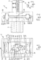
1 einen Querschnitt eines Teleskopgestänges nach der Erfindung in der Ebene I-I entsprechend den Pfeilen von rechts nach links gesehen, jedoch ohne eine rechte Gehäusehälfte eines in 2 gezeigten Gehäuses, 1 a cross section of a telescopic rod according to the invention in the plane II as seen from the arrows from right to left, However, without a right half of a housing in 2 shown housing,

2 eine in der Länge abgebrochene Seitenansicht des Teleskopgestänges von 1 in gleichem Maßstab, 2 a broken in length side view of the telescopic boom of 1 on the same scale,

3 eine abgebrochene Seitenansicht einer Verzahnung einer Teleskopstange in Richtung der Pfeile III-III von 2 gesehen, 3 a broken side view of a toothing of a telescopic rod in the direction of the arrows III-III of 2 seen,

4 eine vergrößerte Darstellung des Querschnittes von 1 in geschlossener Stellung einer zwischen zwei Teleskopteilen gebildeten Kupplung (beide Teleskopteile in Längsrichtung relativ zueinander fixiert und in Drehrichtung relativ zueinander arretiert), 4 an enlarged view of the cross section of 1 in the closed position of a coupling formed between two telescopic parts (both telescopic parts fixed in the longitudinal direction relative to each other and locked in the direction of rotation relative to each other),

5 den Querschnitt von 4 bei geöffneter Stellung der zwischen den beiden Teleskopteilen gebildeten Kupplung (beide Kupplungsteile in Längenrichtung relativ zueinander unfixiert, jedoch in Drehrichtung relativ zueinander wieder arretiert), 5 the cross section of 4 in the open position of the coupling formed between the two telescopic parts (both coupling parts in the length direction unfixed relative to each other, but locked in the direction of rotation relative to each other again),

6 schematisch eine Seitenansicht des Teleskopgestänges gemäß den anderen Figuren, eingebaut in einen Gasherd, welcher nur teilweise dargestellt ist, 6 1 is a schematic side view of the telescopic linkage according to the other figures, installed in a gas stove, which is shown only partially,

7 einen Querschnitt des Teleskopgestänges gemäß 6. 7 a cross section of the telescopic rod according to 6 ,

Gemäß den 6 und 7 enthält das Teleskopgestänge 2 gemäß der Erfindung ein Teleskoprohr 4 und eine in deren eines Ende eingesetzte Teleskopstange 5, welche in nachfolgend noch beschriebener Weise wahlweise in Axialrichtung relativ zueinander verstellbar und in gewünschter Länge des Teleskopgestänges 2 relativ zueinander fixierbar und defixierbar sind, und mindestens im aixalfixierten Zustand auch in Drehrichtung relativ zueinander arretierbar sind. Diese beiden Teleskopteile 4 und 5 sind an ihren voneinander abgewandten Enden einerseits über ein Kugelgelenk 6 mit der Welle 8 eines Knebels 10 und andererseits über ein weiteres Kugelgelenk 12 mit der Gashahnwelle 13 eines Kückens oder Ventilkörpers eines Gashahnes 14 eines Gasbrenners 16 drehfest verbunden. Der Gasbrenner 16 befindet sich an einer Kochstelle in einer Kochmulde des Gasherdes. Die Knebelwelle 8 ist mit dem Knebel 10 drehfest verbunden und manuell drehbar sowie axial verschiebbar in einer Schalteinheit 18 gelagert, welche auf der Vorderseite des Gasherdes an einer Blende 20 unbeweglich befestigt ist.According to the 6 and 7 contains the telescopic linkage 2 according to the invention, a telescopic tube 4 and a telescopic rod inserted in one end thereof 5 , Which in the manner described below selectively adjustable in the axial direction relative to each other and in the desired length of the telescopic linkage 2 can be fixed relative to each other and defixed, and at least in aixalfixierten state in the direction of rotation relative to each other can be locked. These two telescope parts 4 and 5 are at their opposite ends on the one hand via a ball joint 6 with the wave 8th a gag 10 and on the other hand via another ball joint 12 with the gas tap shaft 13 a chimney or valve body of a gas tap 14 a gas burner 16 rotatably connected. The gas burner 16 is located at a cooking place in a cooktop of the gas stove. The gag wave 8th is with the gag 10 rotatably connected and manually rotatable and axially displaceable in a switching unit 18 stored, which on the front of the gas cooker on a panel 20 is fixed immovably.

Die Gashahnwelle 13 (oder der mit ihr verbundene Teleskopteil 4) ist mit einer quer wegragenden Anschlagnase 22 versehen, in dessen Drehbewegungsweg zwei Anschläge 24 liegen, die am Gehäuse des Gashahns 14 vorgesehen sind und den Drehwinkel α der Gashahnwelle 13 und damit auch des mit ihr verbundenen Teleskopteiles 4 begrenzen, beispielsweise auf ungefähr 205° Grad. Wie nachfolgend noch beschrieben wird, ist der mit dem Knebel 10 verbundene andere Teleskopteil 5 um einen Überdrehungs-Winkelbereich β von etwa 15° Grad bis 30° Grad über den Drehwinkel α hinaus drehbar.The gas tap shaft 13 (or the telescope part connected to it 4 ) is with a transversely projecting stop lug 22 provided, in whose Drehbewegungsweg two attacks 24 lying on the housing of the gas tap 14 are provided and the rotational angle α of the gas cock shaft 13 and thus also the telescope part connected to it 4 limit, for example, to about 205 degrees. As will be described below, the one with the gag 10 connected other telescope part 5 by an over-rotation angle range β of about 15 ° degrees to 30 ° degrees beyond the rotation angle α out.

Durch das Teleskopgestänge 2 kann eine am Gasbrenner 16 oder am Gashahn 14 angeordnete Zündsicherung 26 durch manuelles Verschieben (eindrücken) des Knebels 10 betätigt werden, wie dies im Stand der Technik bekannt ist. Sie hat in bekannter Weise die Funktion eines Sicherheitsventils, welches durch das genannte Eindrücken des Knebels 10 geöffnet wird und beim Loslassen des Knebels 10 automatisch wieder schließt, außer es brennt am Gasbrenner 16 eine Gasflamme, welche das Sicherheitsventil durch ein Thermoelement in Offenstellung hält. Beim Erlöschen der Gasflamme kühlt das Thermoelement des Sicherheitsventils ab, so dass es automatisch wieder schließt.Through the telescopic linkage 2 can one at the gas burner 16 or at the gas tap 14 arranged ignition fuse 26 by manually moving (pushing in) the knob 10 be actuated, as is known in the art. She has in a known manner the function of a safety valve, which by the said impressions of the gag 10 is opened and when releasing the gag 10 automatically closes again, except it burns on the gas burner 16 a gas flame holding the safety valve in the open position by a thermocouple. When the gas flame goes out, the thermocouple of the safety valve cools down so that it automatically closes again.

Das Teleskopgestänge 2 muß somit Drehmomente zur Betätigung des Gashahnes 14 als auch Schubkräfte zur Betätigung der Zündsicherung 26 übertragen können und für die Betätigung der Zündsicherung 26 auch axial verschiebbar sein.The telescopic linkage 2 thus has torques for actuating the gas tap 14 as well as shear forces to operate the ignition fuse 26 can transmit and for the operation of the ignition fuse 26 also be axially displaceable.

Das Teleskoprohr 4 und die Teleskopstange 5 können gegenseitig vertauscht werden. In 6 ist die Teleskopstange 5 über das eine Kugelgelenk 6 mit der Knebelwelle 8 drehfest verbunden und das Teleskoprohr 4 ist über das andere Kugelgelenk 12 mit der Gashahnwelle 13 drehfest verbunden.The telescopic tube 4 and the telescopic pole 5 can be interchanged. In 6 is the telescopic pole 5 over the one ball joint 6 with the toggle shaft 8th rotatably connected and the telescopic tube 4 is over the other ball joint 12 with the gas tap shaft 13 rotatably connected.

Gemäß der Erfindung wird unter Ausnutzung der jeweiligen Dreh-Endstellungen der Gashahnwelle 13 und des mit ihr verbundenen Teleskoprohres 4 an den Anschlägen 24 des Gashahnes 14 durch Überdrehen des Knebels 10 eine Längenfixierung und eine Dreharretierung zwischen den beiden Teleskopteilen 4 und 5 je nach Drehrichtung des Knebels 10 bewirkt oder aufgehoben.According to the invention, taking advantage of the respective rotational end positions of the gas cock shaft 13 and the telescopic tube connected to it 4 at the attacks 24 of the gas tap 14 by over-turning the gag 10 a length fixation and a Dreharretierung between the two telescopic parts 4 and 5 depending on the direction of rotation of the gag 10 effected or canceled.

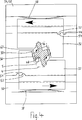
Zu diesem Zweck ist gemäß den 1, 4 und 5 an der Verbindungsstelle der ineinander gesteckten Teleskopteile 4 und 5 ein Mechanismus vorgesehen, welcher ein oder mehrere, gemäß den Zeichnungen vorzugsweise zwei mit einer Verzahnung 30 versehene Sperrkörper 32 aufweist. Die Sperrkörper 32 sind in einem Gehäuse 34 quer zur Teleskoplängsrichtung verschiebbar gelagert und umgreifen im Überdrehungs-Winkelbereich β eine entgegengesetzte Verzahnung 36, welche an der Teleskopstange 5 ortsfest angebracht ist. Dabei verrasten die beiden Verzahnungen 30 und 36 in den Endstellungen des Überdrehungs-Winkelbereiches β miteinander derart, dass ein „Umgreifdruck” bzw. eine Klemmwirkung zwischen der Teleskopstange 5 und den Sperrkörpern 32 erzeugt wird, welche kontinuierlich wirkt und durch Federelemente 38 kontinuierlich aufrechterhalten und verstärkt wird. Durch diesen „Umgreifdruck” und die miteinander in Eingriff stehenden Verzahnungen 30 und 36 werden die beiden Teleskopteile 4 und 5 so fixiert, dass die zum Betätigen des Thermoelements der Zündsicherung 26 erforderlichen Drücke- und Hubbewegungen in Längsrichtung des Teleskopgestänges 2 übertragen werden können.For this purpose, according to the 1 . 4 and 5 at the junction of the nested telescope parts 4 and 5 a mechanism is provided, which one or more, according to the drawings, preferably two with a toothing 30 provided locking body 32 having. The locking bodies 32 are in a housing 34 mounted displaceably transversely to the telescopic longitudinal direction and engage in the over-rotation angle range β opposite toothing 36 , which on the telescopic pole 5 is fixed in place. The two gears lock 30 and 36 in the end positions of the over-rotation angle range β with each other such that a "gripping pressure" or a clamping action between the telescopic rod 5 and the blocking bodies 32 is generated, which acts continuously and by spring elements 38 is continuously maintained and strengthened. Through this "gripping pressure" and the intermeshing teeth 30 and 36 become the two telescope parts 4 and 5 fixed so that the for actuating the thermocouple of the ignition fuse 26 required pressures and strokes in the longitudinal direction of the telescopic boom 2 can be transmitted.

Zusätzlich sind Dreh-Arretiermittel in Form von Verrastungsmitteln 40 vorgesehen, welche bewirken, daß die zum Betätigen des Gashahnes 14 erforderlichen Drehbewegungen des Knebels 10 durch das Teleskopgestänge 2 ohne Leerlauf auch im Überdrehungs-Winkelbereich β übertragen werden können.In addition, rotary locking means are in the form of latching means 40 provided, which cause that for actuating the gas tap 14 required rotational movements of the gag 10 through the telescopic linkage 2 can be transmitted without idling in the over-rotation angle range β.

Die Längenfixierung des Teleskopgestänges
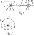
 2 ist durch die Teleskopstange 5 betätigbar, welche innerhalb des Überdrehungs-Winkelbereiches β in dem Teleskoprohr 4 relativ zu diesem verdrehbar ist. Dieses gegenseitige Verdrehen von Teleskoprohr 4 und Teleskopstange 5 setzt dann ein, wenn der Knebel 10 seine betreffenden Endstellung am Ende des Drehwinkelbereiches α an einem der Anschläge 24 erreicht hat und somit von dort an die Gashahnwelle 13 und das an ihm befestigte Teleskopteil 4 nicht weiter drehbar ist.The length fixation of the telescopic linkage 2 is through the telescopic rod 5 which can be actuated within the range of the over-rotation angle β in the telescopic tube 4 is rotatable relative to this. This mutual twisting of telescopic tube 4 and telescopic pole 5 then starts when the gag 10 its respective end position at the end of the rotation angle range α at one of the stops 24 has reached and thus from there to the gas cock shaft 13 and the telescopic part attached to it 4 is not rotatable.

Die Teleskopstange 5 ist in ihrem Querschnitt als Mitnehmer geformt, beispielsweise gemäß den Zeichnungen als Drehkreuz, und ist mit den im Gehäuse 34 angeordneten Sperrkörpern 32 derart in Eingriff, dass sie beim Drehen der Teleskopstange 5 die Sperrkörper 32 im Gehäuse 34 je nach Drehrichtung vor oder zurück quer zur Teleskoplängsrichtung bewegt. Für jeden Sperrkörper 32 ist an der Teleskopstange 5 ein einstückig an ihr angeformter Mitnehmervorsprung 44 in Form einer Längsrippe vorgesehen, welche in eine Mitnehmerausnehmung 46 des betreffenden Sperrkörpers 32 eingreift. Ein anderer an der Teleskopstange 5 einstückig angeformter Vorsprung 48 in Form einer Längsrippe ist mit der Verzahnung 30 dieser Teleskopstange 5 versehen, welche mit der Sperrkörper-Verzahnung 36 in Eingriff bringbar ist zur formschlüssigen Fixierung der Teleskopstange 5 relativ zum Teleskoprohr 4 durch den Sperrkörper 32.The telescopic pole 5 is shaped in its cross-section as a driver, for example according to the drawings as a turnstile, and is in the housing 34 arranged blocking bodies 32 engaged in such a way that when turning the telescopic rod 5 the blocking body 32 in the case 34 depending on the direction of rotation moved forward or back across the telescopic longitudinal direction. For every locking body 32 is at the telescopic pole 5 an integrally formed on her Mitnehmervorsprung 44 provided in the form of a longitudinal rib, which in a Mitnehmerausnehmung 46 of the respective blocking body 32 intervenes. Another at the telescopic pole 5 integrally formed projection 48 in the form of a longitudinal rib is with the toothing 30 this telescopic pole 5 provided, which with the locking body toothing 36 can be brought into engagement for the positive fixing of the telescopic rod 5 relative to the telescopic tube 4 through the blocking body 32 ,

In dem Gehäuse 34 sind Führungen 50 zur Führung der Sperrkörper 32 in Teleskop-Querrichtung gebildet. In diesen Führungen befinden sich die Sperrkörper 32. Die Sperrkörper 32 sind entsprechend der Teleskopstange 5 geformt. Sie haben jeweils die Mitnehmerausnehmung 46 in Form einer Längsnut und die zur Zahnstangen-Verzahnung 30 passende Sperrkörper-Verzahnung 36. Die beiden Verzahnungen sind je nach relativer Drehposition der beiden Teleskopteile 4 und 5 miteinander in Eingriff oder nicht in Eingriff. Sie bilden somit eine Zahnkupplung zur Übertragung von Längskräften und Längsbewegungen. Gleichzeitig bilden die Sperrkörper 32 mit der Teleskopstange 5 eine Klemmkupplung. Es könnte auch nur eine der beiden Kupplungsarten vorgesehen sein. Um diese beiden Lagezustände, Verzahnungen 30 und 36 in Eingriff oder nicht in Eingriff, der Sperrelemente 32 zu fixieren oder arretieren, sind die genannten Verrastungsmittel 40 vorgesehen.In the case 34 are guides 50 for guiding the blocking body 32 formed in telescopic transverse direction. In these guides are the locking body 32 , The locking bodies 32 are according to the telescopic rod 5 shaped. They each have the Mitnehmerausnehmung 46 in the form of a longitudinal groove and the rack teeth 30 suitable locking body toothing 36 , The two gears are depending on the relative rotational position of the two telescopic parts 4 and 5 engaged or disengaged. They thus form a toothed coupling for the transmission of longitudinal forces and longitudinal movements. At the same time form the blocking body 32 with the telescopic rod 5 a clamp coupling. It could also be provided only one of the two types of couplings. To these two situations, gearing 30 and 36 engaged or disengaged, the locking elements 32 to fix or lock, are the mentioned latching means 40 intended.

Die Verrastungsmittel 40 bestehen vorzugsweise aus mindestens einer halbrundförmigen Erhebung 52, welche an den Sperrkörpern 32 gebildet sind, und an entsprechender Stelle im Gehäuse 34 gebildeten, dazu passenden Vertiefungen 54. Die Lage und die Form dieser Erhebungen 52 und Vertiefungen 54 ist zum Verrasten und damit zum Fixieren der Sperrkörper 32 so gewählt, dass ein kontinuierlicher „Umgreifdruck oder Spanndruck” auf die Teleskopstange 5 ausgeübt wird, wenn sie relativ zum Teleskoprohr 4 in Teleskoplängsrichtung fixiert ist. Dieser Druck und die Stärke der Verrastung kann durch entsprechende Auswahl der Federelemente 38 beliebig dimensioniert werden. Die Federelemente 38 können entsprechend den Zeichnungen Blattfedern oder andere Federn sein. Ferner ist es möglich, die Federn 38 an dem Gehäuse 34 oder dem betreffenden Sperrkörper 32 einstückig anzuformen oder aus Kunststoff anzuspritzen. Das Gehäuse 34 und die Sperrkörper 32 können mit den Federelementen einstückig oder getrennt aus Kunststoff bestehen. Andere mögliche Materialien sind Metall.The latching means 40 preferably consist of at least one semicircular elevation 52 , which on the blocking bodies 32 are formed, and at the appropriate place in the housing 34 formed, matching wells 54 , The location and shape of these surveys 52 and depressions 54 is for locking and thus fixing the locking body 32 chosen so that a continuous "gripping pressure or clamping pressure" on the telescopic rod 5 is exercised when relative to the telescopic tube 4 fixed in telescopic longitudinal direction. This pressure and the strength of the locking can be selected by appropriate selection of the spring elements 38 be dimensioned arbitrarily. The spring elements 38 may be leaf springs or other springs according to the drawings. It is also possible to use the springs 38 on the housing 34 or the respective blocking body 32 to mold in one piece or to inject from plastic. The housing 34 and the locking bodies 32 can be made in one piece with the spring elements or separated from plastic. Other possible materials are metal.

Das Gehäuse 34 besteht aus einer mit Bezug auf 2 linken Gehäusehälfte 56 und einer rechten Gehäusehälfte 58. Mindestens eine dieser beiden Gehäusehälften ist an dem Teleskoprohr 4 befestigt oder einstückig angeformt. In ihnen sind einander gegenüberliegende Vertiefungen oder Nuten gebildet, welche zusammen die Führung 50 für den mindestens einen Sperrkörper 32 ergeben.The housing 34 consists of a related to 2 left housing half 56 and a right half of the housing 58 , At least one of these two housing halves is on the telescopic tube 4 attached or integrally formed. In them, opposing depressions or grooves are formed, which together form the guide 50 for the at least one locking body 32 result.

Gemäß 3 können die Verzahnungen 30 und 36 die Form einer Sägezahn-Verzahnung haben, deren die Druckkräfte aufzunehmende Flanken 60 im wesentlichen rechtwinklig zur Teleskoplängsrichtung sich erstrecken. Jedoch ist auch jede andere Zahnform möglich. Die Zähne der Verzahnungen 30 und 36 erstrecken sich rechtwinklig zur Teleskoplängsrichtung.According to 3 can the gears 30 and 36 have the shape of a sawtooth toothing, whose pressure forces flanks to be absorbed 60 extend substantially perpendicular to the telescopic longitudinal direction. However, any other tooth shape is possible. The teeth of the gears 30 and 36 extend at right angles to the telescopic longitudinal direction.

Aus den 1, 4 und 5 ist ersichtlich, daß die äußere Querschnittsform der Teleskopstange 5 und die Innenquerschnittsform des Teleskoprohres 4 nicht kreisförmig sind, sondern derart, dass sie mit Ausnahme des Überdrehung-Winkelbereiches β in beiden Drehrichtungen formschlüssig miteinander verbunden sind, so dass zwischen ihnen Drehmomente in beiden Drehrichtungen übertragen werden können. Die Innenwand 62 und damit die Innenquerschnittsform des Teleskoprohres 4 ist im Überdreh-Winkelbereich β mit einer Längsnut 64 versehen, innerhalb welcher der Mitnehmervorsprung 44 innerhalb des Überdreh-Winkelbereiches β ohne Mitnahme der Teleskopstange 5 drehbar ist, jedoch im Einstell-Drehwinkelbereich α an der einen oder anderen Seitenwand der Längsnut 64 anliegt und dadurch das Teleskoprohr 4 im Einstell-Drehwinkelbereich α zwischen den beiden Anschlägen 24 mitdreht. Ferner hat die Innenwand 62 des Teleskoprohres 4 einen sich mit radialem Abstand von der Teleskopstangen-Verzahnung 30 kreisförmig um die Drehachse der Teleskopstange 5 erstreckenden Bogenbereich 66, innerhalb von welchem die Zahnstangen-Verzahnung 30 um den Überdrehungs-Winkelbereich β drehbar ist.From the 1 . 4 and 5 It can be seen that the outer cross-sectional shape of the telescopic rod 5 and the inner cross-sectional shape of the telescopic tube 4 are not circular, but such that they are positively connected to one another in all rotational directions with the exception of the over-rotation angle range β, so that torques in both directions of rotation can be transmitted between them. The inner wall 62 and thus the inner cross-sectional shape of the telescopic tube 4 is in the over-rotation angle range β with a longitudinal groove 64 provided within which the driver projection 44 within the overtravel angular range β without entrainment of the telescopic rod 5 is rotatable, but in the adjustment rotation angle range α on one or the other side wall of the longitudinal groove 64 rests and thereby the telescopic tube 4 in the setting rotation angle range α between the two stops 24 rotates. Furthermore, the inner wall has 62 of the telescopic tube 4 one at a radial distance from the telescoping rod toothing 30 circular around the axis of rotation of the telescopic rod 5 extending arch area 66 inside of which the rack and pinion teeth 30 is rotatable about the over-rotation angle range β.

Die halbrundförmige Erhebung 52 des Verrastungsmittels 40 ist gemäß den 1, 4 und 5 in einem in Richtung zur Teleskoplängsachse nach innen gerichteten Teil der Sperrkörper 32 gebildet. Die dazu passenden Vertiefungen 54 sind in einer entgegengesetzt, von der Teleskoplängsachse nach außen gerichteten Fläche des betreffenden Gehäuseteils 56 und 58 gebildet. Die Erhebung 52 und dazu passende Vertiefung 54 können vertauscht angeordnet werden. Es sind mindestens zwei Vertiefungen 54 erforderlich, welche in einem dem Überdreh-Winkelbereich β entsprechenden Längsabstand voneinander angeordnet sind, so daß die zugehörige Erhebung 52 jeweils in der Endstellung des Überdreh-Winkelbereiches β in die eine oder andere Vertiefung 54 eingreift. Selbstverständlich sind auch mehrere Erhebungen 52 und dazu passende Vertiefungen 54 möglich.The semicircular elevation 52 of the latching means 40 is in accordance with the 1 . 4 and 5 in a direction towards the telescopic longitudinal axis inwardly directed part of the locking body 32 educated. The matching wells 54 are in an opposite, directed from the telescopic longitudinal axis outward surface of the respective housing part 56 and 58 educated. The assessment 52 and matching well 54 can be arranged reversed. There are at least two depressions 54 required, which are arranged in a the over-rotation angle range β corresponding longitudinal distance from each other, so that the associated elevation 52 each in the end position of the over-rotation angle range β in one or the other recess 54 intervenes. Of course, there are also several surveys 52 and matching wells 54 possible.

Claims (10)

Gasherd mit mindestens einer Brennstelle (16), welcher ein Gashahn (14) zugeordnet ist, der über ein Teleskopgestänge (2) durch manuelles Drehen eines Drehkörpers (10) einer im Bereich einer Frontplatte (20) befestigten Schalteinheit (18) betätigbar ist, wobei der Einstell-Drehbereich (α) des Gashahns durch zwei Gashahnanschläge (24) begrenzt ist und die Länge des Teleskopgestänges, welches mindestens zwei axial ineinander verschiebbare Teleskopteile (4, 5) aufweist, einstellbar und fixierbar ist, und mit einer Zündsicherung (26), die durch axiales Bewegen des Teleskopgestänges (2) mittels des Drehkörpers (10) betätigbar ist, dadurch gekennzeichnet, dass die beiden Teleskopteile (4, 5) um einen begrenzten Drehwinkelbereich (β) relativ zueinander um ihre Längsachse zwischen einer miteinander axial fixierten und einer axial unfixierten Stellung drehbar sind durch Drehen des Drehkörpers (10) in der einen oder anderen Drehrichtung über den Einstell-Drehbereich (α) hinaus, und dass die beiden Teleskopteile (4, 5) durch das Drehen relativ zueinander mindestens in der axial fixierten Stellung auch in Drehrichtung relativ zueinander arretierbar sind bzw. durch Drehen in Gegendrehrichtung über den Einstell-Drehbereich (α) hinaus wieder dearretierbar sind.Gas stove with at least one burner ( 16 ), which is a gas tap ( 14 ), which is connected via a telescopic linkage ( 2 ) by manually rotating a rotary body ( 10 ) one in the area of a front panel ( 20 ) attached switching unit ( 18 ) is actuated, wherein the setting rotational range (α) of the gas tap by two gas strokes ( 24 ) is limited and the length of the telescopic linkage, which at least two axially telescopically telescoping parts ( 4 . 5 ), is adjustable and fixable, and with a Zündsicherung ( 26 ) by axial movement of the telescopic linkage ( 2 ) by means of the rotary body ( 10 ) is actuated, characterized in that the two telescopic parts ( 4 . 5 ) are rotatable about a limited angle of rotation range (β) relative to each other about their longitudinal axis between an axially fixed and an axially unfixed position by rotating the rotary body (3). 10 ) in one or the other direction of rotation beyond the setting rotational range (α) addition, and that the two telescopic parts ( 4 . 5 ) by rotation relative to each other at least in the axially fixed position in the direction of rotation relative to each other can be locked or by rotating in reverse direction over the adjustment rotation range (α) out again dearretierbar. Gasherd nach Anspruch 1, dadurch gekennzeichnet, dass der eine Teleskopteil ein Teleskoprohr (4) und der andere Teleskopteil eine in das Teleskoprohr (4) hineinragende Teleskopstange (5) mit einer Verzahnung (36) ist, deren Zähne quer zur Stangenlängsrichtung verlaufen, und dass das Teleskoprohr (4) mit einer Gegenverzahnung (32) versehen ist, deren Zähne durch Drehung der beiden Teleskopteile über den Einstell-Drehbereich (a) hinaus relativ zueinander in Eingriff und außer Eingriff miteinander bringbar sind.Gas stove according to claim 1, characterized in that the one telescope part is a telescopic tube ( 4 ) and the other telescope part into the telescopic tube ( 4 ) projecting telescopic rod ( 5 ) with a toothing ( 36 ), whose teeth extend transversely to the rod longitudinal direction, and that the telescopic tube ( 4 ) with a counter-toothing ( 32 ) is provided whose teeth by rotation of the two telescopic parts beyond the adjustment rotation range (a) out relative to each other in engagement and can be brought out of engagement with each other. Gasherd nach Anspruch 1 oder 2, dadurch gekennzeichnet, dass Klemmverbindungsmittel (30, 36) zur Klemmverbindung der beiden Teleskopteile (4, 5) vorgesehen sind, welche durch Drehen des mit dem Drehkörper (10) drehfest verbundenen Teleskopteils (5) relativ zu dem von einem der beiden Gashahnanschläge (24) drehblockierten Teleskopteil (4) in und außer Klemmeingriff miteinander bringbar sind zur axialen Fixierung und/oder Drehrichtungs-Arretierung der beiden Teleskopteile (4, 5) relativ zueinander bzw. zur Defixierung und Dearretierung.Gas stove according to claim 1 or 2, characterized in that clamping connection means ( 30 . 36 ) for clamping connection of the two telescopic parts ( 4 . 5 ) are provided, which by turning the with the rotary body ( 10 ) rotatably connected telescopic part ( 5 ) relative to that of one of the two gas taps ( 24 ) rotationally blocked telescope part ( 4 ) can be brought into and out of clamping engagement with each other for the axial fixation and / or rotational direction locking of the two telescopic parts ( 4 . 5 ) relative to each other or for Defixierung and Dearretierung. Gasherd nach einem der Ansprüche 1 bis 3, dadurch gekennzeichnet, dass die Dreh-Arretiermittel Rasten-Mittel (40) aufweisen, welche durch manuelle Drehkraft am Drehkörper (10) gegen die Gegenkraft der Gashahnanschläge (24) in einer Drehrichtung einrastbar und in entgegengesetzter Drehrichtung ausrastbar sind.Gas stove according to one of claims 1 to 3, characterized in that the rotation-locking means detent means ( 40 ), which by manual torque on the rotary body ( 10 ) against the counterforce of the gas stop ( 24 ) can be latched in one direction of rotation and disengaged in the opposite direction of rotation. Gasherd nach einem der Ansprüche 1 bis 4, dadurch gekennzeichnet, dass der radial äußere Teleskopteil (4), in welchen der radial innere Teleskopteil (5) eingesetzt ist, ein relativ zu ihm unbewegliches Gehäuse (34) aufweist, in welchem mindestens ein Sperrkörper (32) quer zur Teleskoplängsrichtung bewegbar geführt ist, dass der radial innere Teleskopteil (5) und der Sperrkörper (32) durch einen Mitnehmer-Eingriff (44, 46) miteinander drehfest verbunden sind, jedoch in Teleskoplängsrichtung relativ zueinander verstellbar sind, und dass der Sperrkörper (32) mit den Mitteln (36) des radial äußeren Teleskopteils (4) zur axialen Fixierung und De-Fixierung und/oder zur Arretierung und Dearretierung in Drehrichtung versehen ist.Gas stove according to one of claims 1 to 4, characterized in that the radially outer telescopic part ( 4 ), in which the radially inner telescopic part ( 5 ), a relatively immovable housing ( 34 ), in which at least one blocking body ( 32 ) is guided movable transversely to the telescopic longitudinal direction, that the radially inner telescopic part ( 5 ) and the blocking body ( 32 ) by a driver intervention ( 44 . 46 ) are rotatably connected to each other, but are adjustable relative to each other in the telescopic longitudinal direction, and that the blocking body ( 32 ) with the means ( 36 ) of the radially outer telescopic part ( 4 ) is provided for axial fixation and de-fixation and / or locking and Dearretierung in the direction of rotation. Gasherd nach Anspruch 4 und 5, dadurch gekennzeichnet, dass der Sperrkörper (32) mit den Rasten-Mitteln (52) des radial äußeren Teleskopteils (52) versehen ist und dass das Gehäuse (34) mit dazu passenden, mit ihnen in und außer Eingriff bringbaren Gegen-Rasten-Mitteln (54) versehen ist.Gas stove according to claim 4 and 5, characterized in that the blocking body ( 32 ) with the locking means ( 52 ) of the radially outer telescopic part ( 52 ) and that the housing ( 34 ) with matching counter-latching means engageable and disengageable therewith ( 54 ) is provided. Gasherd nach Anspruch 5 oder 6, dadurch gekennzeichnet, dass Federmittel (38) vorgesehen sind, welche den mindestens einen Sperrkörper (32) in eine die beiden Teleskopteile in axialer Richtung zueinander fixierende und/oder in Drehrichtung arretierende Stellung drängt. Gas stove according to claim 5 or 6, characterized in that spring means ( 38 ) are provided, which the at least one blocking body ( 32 ) in one of the two telescopic parts in the axial direction to each other fixing and / or arresting in the direction of rotation urges position. Gasherd nach einem der Ansprüche 2 bis 7, dadurch gekennzeichnet, dass der Sperrkörper (32) mit der Gegenverzahnung (30) des Teleskoprohres (4) versehen ist.Gas stove according to one of claims 2 to 7, characterized in that the blocking body ( 32 ) with the counter-toothing ( 30 ) of the telescopic tube ( 4 ) is provided. Gasherd nach einem der Ansprüche 3 bis 8, dadurch gekennzeichnet, dass der Sperrkörper (32) mit mindestens einer Klemmfläche (36) versehen ist, welche mit einer Gegen-Klemmfläche des anderen Teleskopteils durch manuelles Drehen der beiden Teleskopteile (4, 5) relativ zueinander in und außer Eingriff bringbar ist.Gas stove according to one of claims 3 to 8, characterized in that the blocking body ( 32 ) with at least one clamping surface ( 36 ), which with a counter-clamping surface of the other telescopic part by manually rotating the two telescopic parts ( 4 . 5 ) is engageable relative to each other in and out of engagement. Gasherd nach einem der Ansprüche 5 bis 9, dadurch gekennzeichnet, dass der radial äußere Teleskopteil (4) einen in Querrichtung wegragenden Mitnehmervorsprung (44) aufweist, welcher in eine Mitnehmerausnehmung (46) des Sperrkörpers (32) ragt und dadurch mit dem Sperrkörper eine ihn in beiden Drehrichtungen im wesentlichen spiegelfrei mitnehmende Kupplung bildet.Gas stove according to one of claims 5 to 9, characterized in that the radially outer telescopic part ( 4 ) a projecting in the transverse direction driving projection ( 44 ), which in a Mitnehmerausnehmung ( 46 ) of the blocking body ( 32 ) and thereby forms with the locking body a him in both directions substantially mirror-free entnehmende coupling.
DE19829286A 1998-06-30 1998-06-30 gas cooker Expired - Fee Related DE19829286B4 (en)

Priority Applications (1)

Application Number Priority Date Filing Date Title
DE19829286A DE19829286B4 (en) 1998-06-30 1998-06-30 gas cooker

Applications Claiming Priority (1)

Application Number Priority Date Filing Date Title
DE19829286A DE19829286B4 (en) 1998-06-30 1998-06-30 gas cooker

Publications (2)

Publication Number Publication Date
DE19829286A1 DE19829286A1 (en) 2000-01-05
DE19829286B4 true DE19829286B4 (en) 2012-03-15

Family

ID=7872569

Family Applications (1)

Application Number Title Priority Date Filing Date
DE19829286A Expired - Fee Related DE19829286B4 (en) 1998-06-30 1998-06-30 gas cooker

Country Status (1)

Country Link
DE (1) DE19829286B4 (en)

Families Citing this family (6)

* Cited by examiner, † Cited by third party
Publication number Priority date Publication date Assignee Title
ES2216396T3 (en) * 1999-09-07 2004-10-16 Bsh Bosch Und Siemens Hausgerate Gmbh TELESCOPIC BAR FOR DOMESTIC APPLIANCES.
ES2208006B1 (en) * 2001-04-05 2005-11-01 Bsh Electrodomesticos España, S.A. TELESCOPIC BAR FOR APPLIANCES.
ES2215426B1 (en) * 2001-04-27 2006-02-01 Bsh Electrodomesticos España, S.A. SWITCHING UNIT WITH ROTATING SWITCH AND PUSH SWITCH.
ITMI20011531A1 (en) * 2001-07-18 2003-01-18 Miglio Emilio S N C DEVICE FOR THE CONTROL OF TAPS FOR COOKING HOBS
DE10159253A1 (en) * 2001-12-03 2003-06-18 Bsh Bosch Siemens Hausgeraete Gas Cooking
CN109668178A (en) * 2018-12-31 2019-04-23 佛山市云米电器科技有限公司 A kind of telescopic folding kitchen range that can remotely close fire

Citations (3)

* Cited by examiner, † Cited by third party
Publication number Priority date Publication date Assignee Title
DE1087220B (en) * 1956-07-06 1960-08-18 Busch Jaeger Duerener Metall Device for the extension of rotary switch shafts on electric cookers u. like
DE8006440U1 (en) * 1979-03-15 1980-06-12 Lindmayr, Franz, Ing. DEVICE FOR ACTUATING THE GAS CONTROL DEVICES OF COOKINGS
DE9420804U1 (en) * 1994-12-23 1995-02-16 Bosch Siemens Hausgeraete Gas stove with switch unit

Patent Citations (4)

* Cited by examiner, † Cited by third party
Publication number Priority date Publication date Assignee Title
DE1087220B (en) * 1956-07-06 1960-08-18 Busch Jaeger Duerener Metall Device for the extension of rotary switch shafts on electric cookers u. like
DE8006440U1 (en) * 1979-03-15 1980-06-12 Lindmayr, Franz, Ing. DEVICE FOR ACTUATING THE GAS CONTROL DEVICES OF COOKINGS
DE9420804U1 (en) * 1994-12-23 1995-02-16 Bosch Siemens Hausgeraete Gas stove with switch unit
EP0718745A2 (en) * 1994-12-23 1996-06-26 Bosch-Siemens HausgerÀ¤te GmbH Gas stove with switching unit

Also Published As

Publication number Publication date
DE19829286A1 (en) 2000-01-05

Similar Documents

Publication Publication Date Title
EP3268167B1 (en) Torque wrench
EP1859329B1 (en) Flow regulator
DE19829286B4 (en) gas cooker
DE2624521A1 (en) MANUAL CLUTCH
DE102019208345A1 (en) Differential lock
EP1083388B1 (en) Telescopic linkage for domestic devices
EP3486407A1 (en) Handle element and window handle fittings
DE19745487C2 (en) Handle for gas burners
DE20007948U1 (en) Swivel joint with snap coupling
EP0718745B1 (en) Gas stove with switching unit
DE19702173C1 (en) Socket for gas-union
EP3058277B1 (en) Actuator for a gas valve, gas valve, and range
EP2957682B1 (en) Sanitary fitting with a train rotation mechanism for operating them
EP2013534B1 (en) Adjusting gear mechanism for the adjustment of a spotlight connected to a mounting bracket
DE10159253A1 (en) Gas Cooking
EP1510636A1 (en) Closing device for doors, in particular for cold room doors
DE102010054391A1 (en) Switching device for operating switches at desired level for valve control, has switching elements frontally provided with teeth, where switching elements are in set position in engagement with each other
DE2444121C3 (en) Cover cap for a mixer tap
EP1947289B1 (en) Coupling for a winding shaft of a roller blind
DE4313633A1 (en) Shut-off device
DE2444120C3 (en) Lever for a single-lever mixer tap
EP1255082B1 (en) Switching unit with a rotary and push switch
DE102004034329A1 (en) Gas cooking point has transmission device for transmitting of operating movement to burner, with centrifugal force operated connecting device between sections of transmission device
EP2910282B1 (en) Fire protection flap
DE10122261A1 (en) Drive for a parallel installation window

Legal Events

Date Code Title Description
OM8 Search report available as to paragraph 43 lit. 1 sentence 1 patent law
8110 Request for examination paragraph 44
R018 Grant decision by examination section/examining division
R020 Patent grant now final

Effective date: 20120616

R081 Change of applicant/patentee

Owner name: BSH HAUSGERAETE GMBH, DE

Free format text: FORMER OWNER: BSH BOSCH UND SIEMENS HAUSGERAETE GMBH, 81739 MUENCHEN, DE

Effective date: 20150402

R119 Application deemed withdrawn, or ip right lapsed, due to non-payment of renewal fee