Querverweis auf ähnliche AnmeldungCross-reference to similar application
Diese Anmeldung basiert auf der Japanischen Patentanmeldung mit der Nr. 2017-203 301 , eingereicht am 20. Oktober 2017, welche hierin durch Bezugnahme mit aufgenommen wird.This registration is based on the Japanese patent application No. 2017-203 301 , filed October 20, 2017, which is incorporated herein by reference.
Technisches GebietTechnical field
Die vorliegende Offenbarung betrifft einen Aktuator, der ein Boostdruck-Steuerventil eines Turboladers antreibt.The present disclosure relates to an actuator that drives a boost pressure control valve of a turbocharger.
Stand der TechnikState of the art
Bisher ist ein Aktuator bekannt, der zum Beispiel durch einen Verbindungsmechanismus mit dem Boostdruck-Steuerventil verbunden ist und einen Boostdruck steuert, indem ein Ventilöffnungsgrad des Boostdruck-Steuerventils angepasst wird. Ein Aktuator, der in der Patentliteratur 1 offenbart ist, reduziert eine Geschwindigkeit einer Drehung bzw. Drehgeschwindigkeit, die ausgehend von einem Elektromotor ausgegeben wird, durch ein Untersetzungsgetriebe, und gibt danach die Drehung durch eine Ausgangswelle aus. Ein Drehwinkel der Ausgangswelle wird mit einem Drehwinkelsensor sensiert. Die Ausgangswelle wird durch ein Gehäuse und eine Abdeckung gelagert. In einem Abschnitt der Abdeckung, welche aus Harz hergestellt ist und eine Reaktionskraft aufnimmt, die durch den Betrieb des Aktuators erzeugt wird, sind Verstärkungsrippen ausgebildet.So far, an actuator is known which is connected to the boost pressure control valve, for example, by a connecting mechanism and controls a boost pressure by adjusting a valve opening degree of the boost pressure control valve. An actuator disclosed in Patent Literature 1 reduces a speed of rotation output from an electric motor through a reduction gear, and then outputs the rotation through an output shaft. A rotation angle of the output shaft is sensed with a rotation angle sensor. The output shaft is supported by a housing and a cover. Reinforcing ribs are formed in a portion of the cover, which is made of resin and receives a reaction force generated by the operation of the actuator.
Liste der EntgegenhaltungenList of citations
PatentliteraturPatent literature
Patentliteratur 1: JP 2017-8999 APatent Literature 1: JP 2017-8999 A
Kurzfassung der ErfindungSummary of the invention
In einem Fall einer Maschine, die mit einem Turbolader vorgesehen ist, kann eine Ausgabe der Maschine erhöht werden bzw. zunehmen, indem ein Anschlussdurchmesser eines Umgehungs- bzw. Bypass-Strömungsdurchlasses des Turboladers erhöht wird bzw. zunimmt. Wenn der Anschlussdurchmesser erhöht wird bzw. zunimmt, wird eine Last, welche durch einen Abgasdruck durch das Boostdruck-Steuerventil auf den Aktuator ausgeübt wird, allerdings nachteilhaft erhöht. Daher ist es erforderlich, die Festigkeit der Abdeckung zu erhöhen, die als ein Stützbauteil dient, welches die Ausgangswelle lagert. In der Patentliteratur 1 hält die Abdeckung integral eine elektrische Verdrahtung einer Sensiervorrichtung des Drehwinkelsensors und eines Elektromotors. Daher liegt in Bezug auf eine Auswahl eines Materials der Abdeckung ein extrem niedriger bzw. geringer Freiheitsgrad vor, und dadurch besteht eine Beschränkung in Hinblick auf die Verbesserung der Festigkeit der Abdeckung.In a case of an engine provided with a turbocharger, an output of the engine can be increased or increased by increasing or increasing a port diameter of a bypass flow passage of the turbocharger. If the connection diameter is increased or increases, however, a load which is exerted on the actuator by an exhaust gas pressure through the boost pressure control valve is disadvantageously increased. Therefore, it is necessary to increase the strength of the cover that serves as a support member that supports the output shaft. In the patent literature 1, the cover integrally holds electrical wiring of a sensing device of the rotation angle sensor and an electric motor. Therefore, there is an extremely low or low degree of freedom with respect to a selection of a material of the cover, and there is a limitation in improving the strength of the cover.
Die vorliegende Offenbarung wird in Hinblick auf den vorstehenden Punkt getätigt, und es ist eine Aufgabe der vorliegenden Offenbarung, einen Aktuator vorzusehen, der ein Stützbauteil aufweist, welches eine Ausgangswelle lagert und eine verbesserte Festigkeit aufweist, während der Aktuator eine Struktur zum Halten einer elektrischen Verdrahtung aufweist.The present disclosure is made in view of the above point, and it is an object of the present disclosure to provide an actuator having a support member that supports an output shaft and having improved strength, while the actuator has a structure for holding electrical wiring having.
Ein Aktuator der vorliegenden Offenbarung beinhaltet einen Elektromotor, eine Ausgangswelle, ein Untersetzungsgetriebe, einen Drehwinkelsensor, ein Gehäuse und ein Verdrahtungs-Halterbauteil. Das Untersetzungsgetriebe ist dazu konfiguriert, eine Geschwindigkeit einer Drehung zu reduzieren, die ausgehend von dem Elektromotor ausgegeben wird, und die Drehung mit der reduzierten Geschwindigkeit auf die Ausgangswelle zu übertragen. Der Drehwinkelsensor ist dazu konfiguriert, einen Drehwinkel der Ausgangswelle zu sensieren. Das Gehäuse nimmt den Elektromotor und das Untersetzungsgetriebe auf und stützt bzw. lagert die Ausgangswelle. Das Verdrahtungs-Halterbauteil ist ein getrenntes Bauteil, das von dem Gehäuse getrennt ausgebildet ist, während das Verdrahtungs-Halterbauteil folgendes integral hält: eine Sensiervorrichtung des Drehwinkelsensors; und eine elektrische Verdrahtung des Elektromotors und der Sensiervorrichtung.An actuator of the present disclosure includes an electric motor, an output shaft, a reduction gear, a rotation angle sensor, a housing, and a wiring holder member. The reduction gear is configured to reduce a speed of rotation output from the electric motor and to transmit the rotation at the reduced speed to the output shaft. The rotation angle sensor is configured to sense a rotation angle of the output shaft. The housing houses the electric motor and the reduction gear and supports or supports the output shaft. The wiring holder member is a separate member that is formed separately from the housing, while the wiring holder member integrally holds: a sensing device of the rotation angle sensor; and electrical wiring of the electric motor and the sensing device.
Das Gehäuse beinhaltet ein Verbindereinsetzloch, das sich ausgehend von einer Innenseite zu einer Außenseite des Gehäuses durch das Gehäuse erstreckt. Das Verdrahtungs-Halterbauteil bildet einen Verbinder aus, der einen Endabschnitt der elektrischen Verdrahtung aufnimmt und ausgehend von der Innenseite zu der Außenseite des Gehäuses durch das Verbindereinsetzloch hervorsteht.The housing includes a connector insertion hole that extends through the housing from an inside to an outside of the housing. The wiring holder member forms a connector that receives an end portion of the electrical wiring and protrudes from the inside to the outside of the housing through the connector insertion hole.
Wenn das Verdrahtungs-Halterbauteil den Verbinder aufweist, der durch das Verbindereinsetzloch zu der Außenseite des Gehäuses hervorsteht, können das Gehäuse und das Verdrahtungs-Halterbauteil jeweils durch getrennte Bauteile ausgebildet sein, und es ist möglich, für sowohl das Gehäuse als auch das Verdrahtungs-Halterbauteil ein optimales Material auszuwählen. Wenn das Gehäuse, welches als das Stützbauteil zum Lagern der Ausgangswelle dient, durch ein Material wie beispielsweise Metall oder technischer Kunststoff, welches die hohe Festigkeit aufweist, ausgebildet wird, kann die Festigkeit des Gehäuses gegenüber einer relativ großen Last, die durch die Abgaspulsation ausgeübt wird, gewährleistet werden. Außerdem ist es möglich, die elektrische Verdrahtung zu halten, während ein Kurzschluss der elektrischen Verdrahtung beschränkt wird, wenn das Verdrahtungs-Halterbauteil als ein dielektrischer Körper ausgebildet ist. Ferner kann die Dichtung zwischen dem Verdrahtungs-Halterbauteil und dem Gehäuse nur an einer einzelnen Stelle hergestellt werden, wenn die elektrische Verdrahtung des Elektromotors und der Sensiervorrichtung sich durch den Verbinder zu der Außenseite des Gehäuses erstreckt.When the wiring holder member has the connector protruding through the connector insertion hole to the outside of the housing, the housing and the wiring holder member may each be formed by separate members, and it is possible for both the housing and the wiring holder member choose an optimal material. If the housing serving as the support member for supporting the output shaft is formed by a material such as metal or engineering plastic which has high strength, the strength of the housing can withstand a relatively large load exerted by the exhaust gas pulsation , are guaranteed. It is also possible to keep the electrical wiring while shorting the electrical wiring is limited when the wiring holder member is formed as a dielectric body. Furthermore, the seal between the wiring holder member and the case can be made only at a single place when the electric wiring of the electric motor and the sensing device extends through the connector to the outside of the case.
FigurenlisteFigure list
Die vorliegende Offenbarung wird gemeinsam mit zusätzlichen Aufgaben, Merkmalen und Vorteilen dieser am besten aus der folgenden Beschreibung mit Blick auf die beiliegenden Zeichnungen verstanden werden.
- 1 ein schematisches Diagramm, das ein Ansaug- und Abgassystem einer Maschine mit interner Verbrennung zeigt, bei welcher ein Aktuator gemäß einer ersten Ausführungsform angewendet wird;
- 2 ein beschreibendes Diagramm eines Turboladers;
- 3 eine Perspektivansicht des Aktuators;
- 4 eine Draufsicht des Aktuators;
- 5 eine Querschnittsansicht, wobei der Querschnitt entlang einer Linie V-V in 4 vorgenommen worden ist;
- 6 eine Querschnittsansicht, wobei der Querschnitt entlang einer Linie VI-VI in 4 vorgenommen worden ist;
- 7 ein Diagramm, das einen Zustand zeigt, in welchem ein zweites Gehäusesegment des Aktuators von 4 entfernt ist;
- 8 ein Diagramm, welches das zweite Gehäusesegment, ein Verdrahtungs-Halterbauteil und andere Komponenten anzeigt, die ausgehend von einer Innenseite des zweiten Gehäusesegments ersichtlich sind;
- 9 eine Querschnittsansicht, wobei der Querschnitt entlang einer Linie IX-IX in 8 vorgenommen worden ist;
- 10 eine Querschnittsansicht, wobei der Querschnitt entlang einer Linie X-X in 9 vorgenommen worden ist;
- 11 eine Querschnittsansicht, wobei der Querschnitt entlang einer Linie XI-XI in 9 vorgenommen worden ist;
- 12 ein Diagramm, das einen Zustand inmitten eines Zusammensetzens des zweiten Gehäusesegments und des Verdrahtungs-Halterbauteils miteinander zeigt;
- 13 ein Diagramm, das 8 entspricht und dazu dient, zwei gedachte Geraden zu beschreiben;
- 14 eine Querschnittsansicht, wobei der Querschnitt entlang einer Linie XIV-XIV in 8 vorgenommen worden ist;
- 15 ein Diagramm, das einen Zustand, in welchem ein Passabschnitt eine Drehung des Verdrahtungs-Halterbauteils um einen Positionierungsvorsprung beschränkt, veranschaulicht;
- 16 ein Diagramm, das einen Zustand, in welchem ein Passabschnitt eine Drehung eines Verdrahtungs-Halterbauteils um einen Positionierungsvorsprung beschränkt, bei einem Vergleichsbeispiel veranschaulicht;
- 17 eine Querschnittsansicht eines Verbinders und eines Verbindereinsetzlochs eines Aktuators gemäß einer zweiten Ausführungsform;
- 18 ein Diagramm, welches ein zweites Gehäusesegment, ein Verdrahtungs-Halterbauteil und andere Komponenten eines Aktuators anzeigt, die ausgehend von einer Innenseite des zweiten Gehäusesegments gemäß einer dritten Ausführungsform ersichtlich sind;
- 19 eine Querschnittsansicht, wobei der Querschnitt entlang einer Linie XIX-XIX in 18 vorgenommen worden ist;
The present disclosure, together with additional objects, features and advantages thereof, will best be understood from the following description with reference to the accompanying drawings. - 1 a schematic diagram showing an intake and exhaust system of an internal combustion engine to which an actuator according to a first embodiment is applied;
- 2nd a descriptive diagram of a turbocharger;
- 3rd a perspective view of the actuator;
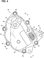
- 4th a top view of the actuator;
- 5 a cross-sectional view, the cross-section along a line VV in 4th has been made;
- 6 a cross-sectional view, the cross-section along a line VI-VI in 4th has been made;
- 7 a diagram showing a state in which a second housing segment of the actuator of 4th is removed;
- 8th a diagram showing the second housing segment, a wiring holder member and other components that are visible from an inside of the second housing segment;
- 9 a cross-sectional view, the cross-section along a line IX-IX in 8th has been made;
- 10th a cross-sectional view, the cross-section along a line XX in 9 has been made;
- 11 a cross-sectional view, the cross-section along a line XI-XI in 9 has been made;
- 12 FIG. 14 is a diagram showing a state in the middle of assembling the second housing segment and the wiring holder member;
- 13 a diagram that 8th corresponds and serves to describe two imaginary straight lines;
- 14 a cross-sectional view, the cross-section along a line XIV-XIV in 8th has been made;
- 15 14 is a diagram illustrating a state in which a fitting portion restricts rotation of the wiring holder member about a positioning protrusion;
- 16 14 is a diagram illustrating a state in which a fitting portion restricts rotation of a wiring holder member about a positioning protrusion in a comparative example;
- 17th a cross-sectional view of a connector and a connector insertion hole of an actuator according to a second embodiment;
- 18th a diagram showing a second housing segment, a wiring holder component and other components of an actuator, which can be seen from an inside of the second housing segment according to a third embodiment;
- 19th a cross-sectional view, the cross-section along a line XIX-XIX in 18th has been made;
Beschreibung der AusführungsformenDescription of the embodiments
Erste AusführungsformFirst embodiment
Nachfolgend werden Ausführungsformen unter Bezugnahme auf die Zeichnungen beschrieben werden. Bei den folgenden Ausführungsformen werden ähnliche Abschnitte, welche bei den Ausführungsformen im Wesentlichen miteinander identisch sind, durch die gleichen Bezugszeichen angezeigt und diese werden nicht redundant beschrieben werden. Wie in 1 gezeigt wird, wird ein Aktuator 10 der ersten Ausführungsform auf eine Maschine 11 mit interner Verbrennung angewendet, die eine Antriebsquelle zum Antreiben eines Fahrzeugs ist.In the following, embodiments will be described with reference to the drawings. In the following embodiments, similar portions, which are substantially identical to each other in the embodiments, are indicated by the same reference numerals and these will not be described redundantly. As in 1 is shown becomes an actuator 10th the first embodiment on a machine 11 applied with internal combustion, which is a drive source for driving a vehicle.
Ansaug- und Abgassystem einer MaschineIntake and exhaust system of a machine
Zuerst wird unter Bezugnahme auf die 1 und 2 ein Ansaug- und Abgassystem der Maschine 11 beschrieben werden. Die Maschine 11 weist einen Ansaugdurchlass 12, welcher eine Ansaugluft zu Zylindern der Maschine 11 leitet, und einen Abgasdurchlass 13, welcher ein Abgas, das bei den Zylindern erzeugt wird, zu der Atmosphäre abführt, auf. Ein Ansaugverdichter 15 eines Turboladers 14 und ein Drosselventil 16 sind in dem Ansaugdurchlass 12 installiert. Das Drosselventil 16 passt die Menge an Ansaugluft an, die der Maschine 11 zugeführt wird. Eine Abgasturbine 17 des Turboladers 14 und ein Katalysator 18 sind in dem Abgasdurchlass 13 installiert. Der Katalysator 18 reinigt das Abgas. Der Katalysator 18 ist ein bekannter Dreiwegekatalysator, welcher eine monolithische Struktur aufweist. Wenn die Temperatur des Katalysators 18 durch das Abgas auf eine Aktivierungstemperatur erhöht wird, reinigt der Katalysator 18 Schadstoffe, die in dem Abgas enthalten sind, durch Oxidation und Reduktion.First, referring to the 1 and 2nd an intake and exhaust system of the machine 11 to be discribed. The machine 11 has an intake passage 12 which intakes air to cylinders of the machine 11 conducts, and an exhaust passage 13 , which exhausts an exhaust gas generated at the cylinders to the atmosphere. An intake compressor 15 of a turbocharger 14 and a throttle valve 16 are in the intake passage 12 Installed. The throttle valve 16 adjusts the amount of intake air that the machine 11 is fed. An exhaust gas turbine 17th of the turbocharger 14 and a catalyst 18th are in the exhaust passage 13 Installed. The catalyst 18th cleans the exhaust gas. The catalyst 18th is a well-known three-way catalyst, which has a monolithic structure. If the temperature of the catalyst 18th is increased by the exhaust gas to an activation temperature, the catalyst cleans 18th Pollutants contained in the exhaust gas through oxidation and reduction.
Die Abgasturbine 17 beinhaltet ein Turbinenrad 21, welches durch das Abgas gedreht wird, das ausgehend von der Maschine 11 ausgegeben wird, und ein Turbinengehäuse 22, welches in einer Spiralform geformt ist und das Turbinenrad 21 aufnimmt. Der Ansaugverdichter 15 beinhaltet ein Verdichterrad 23, welches durch eine Drehkraft des Turbinenrads 21 gedreht wird, und ein Verdichtergehäuse 24, welches in einer Spiralform geformt ist und das Verdichterrad 23 aufnimmt.The exhaust gas turbine 17th includes a turbine wheel 21st which is rotated by the exhaust gas emanating from the engine 11 is issued, and a turbine housing 22 , which is shaped in a spiral shape and the turbine wheel 21st records. The intake compressor 15 includes a compressor wheel 23 , which is caused by a torque of the turbine wheel 21st is rotated, and a compressor housing 24th , which is shaped in a spiral shape and the compressor wheel 23 records.
An dem Turbinengehäuse 22 ist ein Bypass- bzw. Umgehungsdurchlass 25 ausgebildet. Der Umgehungsdurchlass 25 leitet das Abgas, während dieser das Turbinenrad 21 umgeht. Der Umgehungsdurchlass 25 leitet das Abgas, welches in das Turbinengehäuse 22 eintritt, direkt zu einem Abgasauslass des Turbinengehäuses 22. Der Umgehungsdurchlass 25 kann durch ein Bypassventil 26 geöffnet und geschlossen werden. Das Bypassventil 26 ist ein Rückschlagventil, das durch die Ventilwelle 27 an der Innenseite des Turbinengehäuses 22 drehbar gelagert ist.On the turbine housing 22 is a bypass or bypass 25th educated. The bypass passage 25th conducts the exhaust gas while it drives the turbine wheel 21st deals. The bypass passage 25th directs the exhaust gas, which into the turbine housing 22 occurs directly to an exhaust gas outlet of the turbine housing 22 . The bypass passage 25th can by a bypass valve 26 be opened and closed. The bypass valve 26 is a check valve that passes through the valve shaft 27 on the inside of the turbine housing 22 is rotatably mounted.
Der Turbolader 14 beinhaltet den Aktuator 10 als ein Antriebsmittel zum Antreiben des Bypassventils 26. Der Aktuator 10 ist an dem Ansaugverdichter 15 installiert, der von der Abgasturbine 17 weg beabstandet angeordnet ist, um Einflüsse der Wärme des Abgases zu vermeiden. Der Turbolader 14 beinhaltet einen Verbindungsmechanismus 29, der die Ausgabe des Aktuators 10 an das Bypassventil 26 überträgt. Der Verbindungsmechanismus 29 ist ein sogenanntes Gelenkviereck. Der Verbindungsmechanismus 29 beinhaltet: einen Aktuatorhebel 31, welcher durch den Aktuator 10 gedreht wird; einen Ventilhebel 32, welcher an die Ventilwelle 27 gekoppelt ist; und eine Stange 33, welche ein Drehmoment von dem Aktuatorhebel 31 auf den Ventilhebel 32 überträgt.The turbocharger 14 includes the actuator 10th as a drive means for driving the bypass valve 26 . The actuator 10th is on the intake compressor 15 installed by the exhaust gas turbine 17th is spaced away to avoid influences of the heat of the exhaust gas. The turbocharger 14 includes a link mechanism 29 which is the output of the actuator 10th to the bypass valve 26 transmits. The connection mechanism 29 is a so-called quadrilateral joint. The connection mechanism 29 includes: an actuator lever 31 which by the actuator 10th is rotated; a valve lever 32 which to the valve shaft 27 is coupled; and a pole 33 which have a torque from the actuator lever 31 on the valve lever 32 transmits.
Der Betrieb des Aktuators 10 wird durch eine ECU (Maschinensteuereinheit) 34 gesteuert, die einen Mikrocomputer aufweist. Genauer gesagt steuert die ECU 34 einen Boostdruck des Turboladers 14, indem diese einen Öffnungsgrad des Bypassventils 26 zum Beispiel bei einer hohen Drehgeschwindigkeit der Maschine 11 anpasst. Außerdem öffnet die ECU 34 das Bypassventil 26 vollständig, um den Katalysator 18 mit dem Abgas aufzuwärmen, wenn die Temperatur des Katalysators 18 zum Beispiel zu der Zeit unmittelbar nach dem Kaltstart der Maschine 11 nicht dessen Aktivierungstemperatur erreicht. Auf diese Weise kann das Abgas mit hoher Temperatur, welches seine Wärme nicht an das Turbinenrad 21 verloren hat, zu dem Katalysator 18 geleitet werden, sodass der Katalysator 18 innerhalb einer kurzen Zeitspanne aufgewärmt werden kann.Operation of the actuator 10th is replaced by a ECU (Machine control unit) 34 controlled, which has a microcomputer. More precisely, it controls ECU 34 a boost pressure of the turbocharger 14 by opening the bypass valve 26 for example when the machine is rotating at high speed 11 adjusts. The also opens ECU 34 the bypass valve 26 completely to the catalyst 18th to warm up with the exhaust gas when the temperature of the catalyst 18th for example, at the time immediately after the machine was cold started 11 has not reached its activation temperature. In this way, the high temperature exhaust gas, which does not transfer its heat to the turbine wheel 21st has lost to the catalyst 18th be directed so that the catalyst 18th can be warmed up within a short period of time.
AktuatorActuator
Als nächstes wird der Aktuator 10 unter Bezugnahme auf die 3 bis 7 beschrieben werden. Der Aktuator 10 beinhaltet ein Gehäuse 35, einen Elektromotor 36, ein Untersetzungsgetriebe 37, eine Ausgangswelle 38 und einen Drehwinkelsensor 39. Das Gehäuse 35 ist an dem Ansaugverdichter 15 installiert, und der Elektromotor 36, das Untersetzungsgetriebe 37, die Ausgangswelle 38 und der Drehwinkelsensor 39 sind in dem Gehäuse 35 installiert.Next is the actuator 10th with reference to the 3rd to 7 to be discribed. The actuator 10th includes a housing 35 , an electric motor 36 , a reduction gear 37 , an output shaft 38 and a rotation angle sensor 39 . The housing 35 is on the intake compressor 15 installed, and the electric motor 36 , the reduction gear 37 , the output shaft 38 and the rotation angle sensor 39 are in the housing 35 Installed.
Wie in den 3 bis 5 gezeigt wird, beinhaltet das Gehäuse 35 ein erstes Gehäusesegment 41 und ein zweites Gehäusesegment 42. Das zweite Gehäusesegment 42 ist durch Befestigungsbauteile 43 an dem ersten Gehäusesegment 41 festgemacht. Das erste Gehäusesegment 41 und das zweite Gehäusesegment 42 sind zueinander so passend ausgebildet, dass diese darin einen Aufnahmeraum 44 ausbilden.As in the 3rd to 5 shown includes the housing 35 a first housing segment 41 and a second housing segment 42 . The second housing segment 42 is through fastening components 43 on the first housing segment 41 fixed. The first housing segment 41 and the second housing segment 42 are designed to match each other so that they contain a receiving space 44 form.
Wie in den 6 und 7 gezeigt wird, ist der Elektromotor 36 in dem Gehäuse 35 aufgenommen. Genauer gesagt wird der Elektromotor 36 in ein Motoreinsetzloch 46 eingesetzt, das an dem ersten Gehäusesegment 41 ausgebildet ist, und ist durch Schrauben 47 an dem ersten Gehäusesegment 41 fixiert. Eine Wellscheibe 45 ist zwischen dem Elektromotor 36 und einer Bodenoberfläche des Motoreinsetzlochs 46 installiert. Der Elektromotor 36 kann ein beliebiger Elektromotor wie beispielsweise ein bekannter Gleichstrommotor, ein bekannter Schrittmotor oder dergleichen sein.As in the 6 and 7 is shown is the electric motor 36 in the housing 35 added. More specifically, the electric motor 36 in an engine insertion hole 46 used that on the first housing segment 41 is formed, and is by screws 47 on the first housing segment 41 fixed. A corrugated washer 45 is between the electric motor 36 and a bottom surface of the engine insertion hole 46 Installed. The electric motor 36 can be any electric motor such as a known DC motor, a known stepping motor, or the like.
Wie in 5 gezeigt wird, ist die Ausgangswelle 38 durch ein Lager 48, welches an dem ersten Gehäusesegment 41 installiert ist, und ein Lager 49, welches an dem zweiten Gehäusesegment 42 installiert ist, drehbar gelagert. Ein Endabschnitt der Ausgangswelle 38 steht ausgehend von dem Gehäuse 35 nach außen hervor. Der Aktuatorhebel 31 ist an der Außenseite des Gehäuses 35 an der Ausgangswelle 38 fixiert. Ein Stecker 50 ist an einen Abschnitt des ersten Gehäusesegments 41 pressgepasst, welcher sich an der anderen Endseite der Ausgangswelle 38 entlang einer gedachten Erstreckungslinie der Ausgangswelle 38 befindet.As in 5 is shown is the output shaft 38 through a camp 48 , which on the first housing segment 41 is installed and a warehouse 49 which on the second housing segment 42 is installed, rotatably mounted. An end portion of the output shaft 38 stands starting from the housing 35 outwards. The actuator lever 31 is on the outside of the case 35 on the output shaft 38 fixed. A plug 50 is to a section of the first housing segment 41 press fit which is on the other end side of the output shaft 38 along an imaginary extension line of the output shaft 38 located.
Wie in den 5 bis 7 gezeigt wird, ist das Untersetzungsgetriebe 37 ein Stirnraduntersetzungsgetriebe, das die Geschwindigkeit der Drehung reduziert, die ausgehend von dem Elektromotor 36 ausgegeben wird, und die Drehung mit der reduzierten Geschwindigkeit auf die Ausgangswelle 38 überträgt. Das Untersetzungsgetriebe 37 beinhaltet ein Ritzel 51, ein erstes Zwischenzahnrad 52, ein zweites Zwischenzahnrad 53 und ein Endzahnrad 54. Das Ritzel 51 ist an einer Motorwelle 55 des Elektromotors 36 fixiert. Das erste Zwischenzahnrad 52 ist durch eine erste Metallwelle 56 drehbar gelagert und beinhaltet: ein erstes externes Zahnrad 57 mit großem Durchmesser, welches mit dem Ritzel 51 in Eingriff steht; und ein erstes externes Zahnrad 58 mit kleinem Durchmesser, das einen Durchmesser aufweist, der kleiner ist als ein Durchmesser des ersten externen Zahnrads 57 mit großem Durchmesser. Zwei primäre Scheiben 59 sind jeweils an einer Stelle zwischen dem ersten Zwischenzahnrad 52 und dem ersten Gehäusesegment 41 und einer Stelle zwischen dem ersten Zwischenzahnrad 52 und dem zweiten Gehäusesegment 42 installiert. Das zweite Zwischenzahnrad 53 ist durch eine zweite Metallwelle 61 drehbar gelagert und beinhaltet: ein zweites externes Zahnrad 62 mit großem Durchmesser, welches mit dem ersten externen Zahnrad 58 mit kleinem Durchmesser in Eingriff steht; und ein zweites externes Zahnrad 63 mit kleinem Durchmesser, das einen Durchmesser aufweist, der kleiner ist als ein Durchmesser des zweiten externen Zahnrads 62 mit großem Durchmesser. Zwei sekundäre Scheiben 60 sind jeweils an einer Stelle zwischen dem zweiten Zwischenzahnrad 53 und dem ersten Gehäusesegment 41 und einer Stelle zwischen dem zweiten Zwischenzahnrad 53 und dem zweiten Gehäusesegment 42 installiert. Das Endzahnrad 54 ist an der Ausgangswelle 38 fixiert und steht mit dem zweiten externen Zahnrad 63 mit kleinem Durchmesser in Eingriff.As in the 5 to 7 is shown is the reduction gear 37 a Helical reduction gearbox, which reduces the speed of rotation, starting from the electric motor 36 is output, and the rotation at the reduced speed on the output shaft 38 transmits. The reduction gear 37 includes a pinion 51 , a first intermediate gear 52 , a second intermediate gear 53 and a final gear 54 . The pinion 51 is on a motor shaft 55 of the electric motor 36 fixed. The first intermediate gear 52 is through a first metal shaft 56 rotatably mounted and includes: a first external gear 57 with a large diameter, which with the pinion 51 is engaged; and a first external gear 58 with a small diameter that has a diameter that is smaller than a diameter of the first external gear 57 with a large diameter. Two primary disks 59 are each at a point between the first intermediate gear 52 and the first housing segment 41 and a location between the first idler gear 52 and the second housing segment 42 Installed. The second intermediate gear 53 is through a second metal shaft 61 rotatably mounted and includes: a second external gear 62 with large diameter, which with the first external gear 58 engages with small diameter; and a second external gear 63 with a small diameter that has a diameter that is smaller than a diameter of the second external gear 62 with a large diameter. Two secondary disks 60 are each at a point between the second intermediate gear 53 and the first housing segment 41 and a location between the second idler gear 53 and the second housing segment 42 Installed. The final gear 54 is on the output shaft 38 fixed and stands with the second external gear 63 with a small diameter.
Wie in den 5 und 7 gezeigt wird, ist der Drehwinkelsensor 39 ein berührungsloser Sensor, der einen Drehwinkel der Ausgangswelle 38 sensiert, und der Drehwinkelsensor 39 beinhaltet eine Vorrichtung 64 des magnetischen Kreises und eine Sensiervorrichtung 65. Die Vorrichtung 64 des magnetischen Kreises beinhaltet Magneten (die als Generatoren des magnetischen Flusses dienen) 66, 67 und Joche (die als Leiter des magnetischen Flusses dienen) 68, 69. Die Magneten 66, 67 und die Joche 68, 69 bilden einen geschlossenen magnetischen Kreis aus, der in einer Ansicht, die in einer axialen Richtung der Ausgangswelle 38 aufgenommen ist, in einer Bogenform geformt ist. Die Vorrichtung 64 des magnetischen Kreises wird durch ein Halterbauteil 73 des magnetischen Kreises gehalten, das aus einem nicht-magnetischen Material hergestellt ist, und wird integral mit der Ausgangswelle 38 gedreht. Die Sensiervorrichtung 65 ist zum Beispiel eine Hall-IC und ist an einer Innenseite des geschlossenen magnetischen Kreises der Vorrichtung 64 des magnetischen Kreises platziert. Die Sensiervorrichtung 65 ist an dem Gehäuse 35 fixiert. Die grundlegenden Anwendungen und Funktionen der Vorrichtung 64 des magnetischen Kreises und der Sensiervorrichtung 65 sind die gleichen wie jene, die in JP 2014-126 548 A offenbart sind. Der Drehwinkel der Ausgangswelle 38, welcher mit einem Drehwinkelsensor 39 sensiert wird, wird an die ECU 34 ausgegeben (vergleiche 1).As in the 5 and 7 is shown is the rotation angle sensor 39 a non-contact sensor that detects an angle of rotation of the output shaft 38 sensed, and the rotation angle sensor 39 includes a device 64 of the magnetic circuit and a sensing device 65 . The device 64 of the magnetic circuit includes magnets (which serve as generators of the magnetic flux) 66, 67 and yokes (which serve as conductors of the magnetic flux) 68, 69. The magnets 66 , 67 and the yokes 68 , 69 form a closed magnetic circuit which, in one view, is in an axial direction of the output shaft 38 is recorded, is shaped in an arc shape. The device 64 of the magnetic circuit is made by a holder component 73 of the magnetic circuit, which is made of a non-magnetic material, and becomes integral with the output shaft 38 turned. The sensing device 65 For example, is a Hall IC and is on an inside of the closed magnetic circuit of the device 64 of the magnetic circuit. The sensing device 65 is on the case 35 fixed. The basic applications and functions of the device 64 of the magnetic circuit and the sensing device 65 are the same as those in JP 2014-126 548 A are disclosed. The angle of rotation of the output shaft 38 which with a rotation angle sensor 39 is sensed, is to the ECU 34 spent (compare 1 ).
Gehäuse und dessen periphere BauteileHousing and its peripheral components
Als nächstes werden das Gehäuse 35 und dessen periphere Bauteile beschrieben werden. Wie in den 8 und 9 gezeigt wird, beinhaltet der Aktuator 10 das Verdrahtungs-Halterbauteil 71. Das Verdrahtungs-Halterbauteil 71 hält integral: die Sensiervorrichtung 65; und eine elektrische Verdrahtung 72 des Elektromotors 36 und der Sensiervorrichtung 65. Das Halterbauteil 71 des magnetischen Kreises ist ein getrenntes Bauteil, das getrennt von dem Gehäuse 35 ausgebildet ist, und ein Material des Verdrahtungs-Halterbauteils 71 unterscheidet sich von einem Material des Gehäuses 35. Das erste Gehäusesegment 41 und das zweite Gehäusesegment 42 sind aus einem Metallmaterial wie beispielsweise einer Aluminiumlegierung hergestellt. Im Gegensatz dazu ist das Verdrahtungs-Halterbauteil 71 ein dielektrischer Körper und aus Harz hergestellt. Das Verdrahtungs-Halterbauteil 71 bildet ein einsatzgeformtes Produkt aus, in welchem das Verdrahtungs-Halterbauteil 71, die Sensiervorrichtung 65 und die elektrische Verdrahtung 72 in einem Stück miteinander integriert sind. Das Verdrahtungs-Halterbauteil 71 ist durch Schrauben (die als Befestigungsbauteile dienen) 74 an dem zweiten Gehäusesegment 42 fixiert.Next is the case 35 and its peripheral components are described. As in the 8th and 9 is shown includes the actuator 10th the wiring holder component 71 . The wiring bracket component 71 holds integrally: the sensing device 65 ; and electrical wiring 72 of the electric motor 36 and the sensing device 65 . The holder component 71 The magnetic circuit is a separate component that is separate from the housing 35 is formed, and a material of the wiring holder member 71 differs from a housing material 35 . The first housing segment 41 and the second housing segment 42 are made of a metal material such as an aluminum alloy. In contrast, the wiring holder component 71 a dielectric body and made of resin. The wiring bracket component 71 forms an insert molded product in which the wiring holder member 71 , the sensing device 65 and the electrical wiring 72 are integrated in one piece. The wiring bracket component 71 is by screws (which serve as fastening components) 74 on the second housing segment 42 fixed.
Das zweite Gehäusesegment 42 beinhaltet ein Verbindereinsetzloch 76 und ein Positionierungsloch 77. Das Verbindereinsetzloch 76 erstreckt sich durch das zweite Gehäusesegment 42 ausgehend von einer Innenseite zu einer Außenseite des Gehäuses 35, und das Positionierungsloch 77 ist an einer Innenwand des zweiten Gehäusesegments 42 ausgebildet. Das Verdrahtungs-Halterbauteil 71 beinhaltet: einen Hauptkörper 81, welcher derart ausgebildet ist, dass dieser sich entlang der Innenwand des zweiten Gehäusesegments 42 erstreckt; einen Sensorhalter 82, der ausgehend von dem Hauptkörper 81 hervorsteht; einen Verbinder 83; und einen Positionierungsvorsprung 84. Der Sensorhalter 82 steht hin zu dem ersten Gehäusesegment 41 hervor und hält die Sensiervorrichtung 65.The second housing segment 42 includes a connector insertion hole 76 and a positioning hole 77 . The connector insertion hole 76 extends through the second housing segment 42 starting from an inside to an outside of the housing 35 , and the positioning hole 77 is on an inner wall of the second housing segment 42 educated. The wiring bracket component 71 includes: a main body 81 , which is designed such that it extends along the inner wall of the second housing segment 42 extends; a sensor holder 82 starting from the main body 81 protrudes; a connector 83 ; and a positioning tab 84 . The sensor holder 82 faces the first housing segment 41 emerges and holds the sensing device 65 .
Der Positionierungsvorsprung 84 ist in das Positionierungsloch 77 eingepasst. Wie in 10 gezeigt wird, ist ein Querschnitt des Positionierungsvorsprungs 84, welcher senkrecht zu einer Einsetzrichtung des Positionierungsvorsprungs 84 in das Positionierungsloch 77 verläuft, in einer kreisförmigen Gestalt bzw. Form geformt. Die Einsetzrichtung des Positionierungsvorsprungs 84 in das Positionierungsloch 77 ist eine Richtung, die parallel zu einer Achse eines Mittelpunkts AX2 des Positionierungsvorsprungs 84 verläuft. In 10 ist eine Größe eines Spalts zwischen dem Positionierungsvorsprung 84 und dem Positionierungsloch 77 im Vergleich zu einer tatsächlichen Größe des Spalts vergrößert, um ein Verständnis der Struktur zu erleichtern.The positioning advantage 84 is in the positioning hole 77 fitted. As in 10th is a cross section of the positioning protrusion 84 which is perpendicular to an insertion direction of the positioning projection 84 into the positioning hole 77 runs in a circular Shape or shape shaped. The direction of insertion of the positioning tab 84 into the positioning hole 77 is a direction parallel to an axis of a center AX2 of the positioning lead 84 runs. In 10th is a size of a gap between the positioning protrusion 84 and the positioning hole 77 enlarged compared to an actual size of the gap to facilitate understanding of the structure.
Der Verbinder 83 steht ausgehend von der Innenseite zu der Außenseite des Gehäuses 35 durch das Verbindereinsetzloch 76 hervor. Der Verbinder 83 beinhaltet einen Passabschnitt 85, der in das Verbindereinsetzloch 76 eingepasst ist. Wie in 11 gezeigt wird, ist ein Querschnitt des Passabschnitts 85, welcher senkrecht zu einer Einsetzrichtung des Passabschnitts 85 in das Verbindereinsetzloch 76 verläuft, in einer nicht-kreisförmigen Gestalt bzw. Form geformt. Die Einsetzrichtung des Passabschnitts 85 in das Verbindereinsetzloch 76 fällt mit einer Verlängerungsrichtung des Verbinders 83, d. h. einer Hervorstehrichtung des Verbinders 83 zusammen. Ein distaler Endabschnitt des Verbinders 83 ist etwas kleiner als der Passabschnitt 85, aber eine Form eines Querschnitts des distalen Endabschnitts des Verbinders 83 ist grundsätzlich die gleiche wie eine Form eines Querschnitts des Passabschnitts 85 des Verbinders 83. In 11 ist eine Größe eines Spalts zwischen dem Passabschnitt 85 und dem Verbindereinsetzloch 76 im Vergleich zu einer tatsächlichen Größe des Spalts vergrößert, um ein Verständnis der Struktur zu erleichtern.The connector 83 stands from the inside to the outside of the housing 35 through the connector insertion hole 76 forth. The connector 83 includes a pass section 85 that is in the connector insertion hole 76 is fitted. As in 11 is shown is a cross section of the fitting section 85 which is perpendicular to an insertion direction of the fitting section 85 into the connector insertion hole 76 runs, shaped in a non-circular shape. The direction of insertion of the pass section 85 into the connector insertion hole 76 falls with an extension direction of the connector 83 , ie a direction of projection of the connector 83 together. A distal end portion of the connector 83 is slightly smaller than the pass section 85 , but a shape of a cross section of the distal end portion of the connector 83 is basically the same as a shape of a cross section of the fitting section 85 of the connector 83 . In 11 is a size of a gap between the fitting section 85 and the connector insertion hole 76 enlarged compared to an actual size of the gap to facilitate understanding of the structure.
Bei der ersten Ausführungsform ist der Querschnitt des Passabschnitts 85 in einer rechteckigen Gestalt bzw. Form geformt, deren Ecken alle gerundet sind. Genauer gesagt weist der Querschnitt des Passabschnitts 85 die Form auf, welche folgendes beinhaltet: ein Paar von primären geraden Seiten 86, welche parallel zueinander verlaufen; und ein Paar von sekundären geraden Seiten 87, welche parallel zueinander verlaufen und senkrecht zu dem Paar von primären geraden Seiten 86 sind.In the first embodiment, the cross section of the fitting portion 85 shaped in a rectangular shape or shape, the corners of which are all rounded. More specifically, the cross section of the fitting section 85 the shape, which includes: a pair of primary straight sides 86 , which run parallel to each other; and a pair of secondary straight sides 87 which are parallel to each other and perpendicular to the pair of primary straight sides 86 are.
Wie in 9 gezeigt wird, sind der Verbinder 83 und der Positionierungsvorsprung 84 jeweils ausgehend von einer Innenseite des zweiten Gehäusesegments 42 in das Verbindereinsetzloch 76 und das Positionierungsloch 77 eingesetzt. Ein Abstand L1, welcher ausgehend von einem distalen Einsetzende 91 des Verbinders 83 zu einem Einsetzeinlass 92 des Verbindereinsetzlochs 76 gemessen wird, ist länger als ein Abstand L2, welcher ausgehend von einem distalen Einsetzende 93 des Positionierungsvorsprungs 84 zu einem Einsetzeinlass 94 des Positionierungslochs 77 gemessen wird. Bei der ersten Ausführungsform ist ein Abstand L3, welcher ausgehend von einem distalen Einsetzende 96 des Passabschnitts 85 zu dem Einsetzeinlass 92 des Verbindereinsetzlochs 76 gemessen wird, ebenfalls länger als der Abstand L2. Indem diese Beziehungen erfüllt werden, wird zu der Zeit, zu der das Verdrahtungs-Halterbauteil 71 an dem zweiten Gehäusesegment 42 zusammengesetzt wird, wie in 12 gezeigt wird, das distale Ende des Verbinders 83 zuerst in das Verbindereinsetzloch 76 eingepasst, bevor der Positionierungsvorsprung 84 das Positionierungsloch 77 erreicht, und danach wird der Passabschnitt 85 in das Verbindereinsetzloch 76 eingepasst.As in 9 is shown are the connector 83 and the positioning lead 84 each starting from an inside of the second housing segment 42 into the connector insertion hole 76 and the positioning hole 77 used. A distance L1 which starts from a distal insertion end 91 of the connector 83 to an insert inlet 92 the connector insertion hole 76 is measured is longer than a distance L2 which starts from a distal insertion end 93 of the positioning lead 84 to an insert inlet 94 of the positioning hole 77 is measured. In the first embodiment, there is a distance L3 which starts from a distal insertion end 96 the passport section 85 to the insert inlet 92 the connector insertion hole 76 is measured, also longer than the distance L2 . By fulfilling these relationships, at the time the wiring holder member becomes 71 on the second housing segment 42 is composed as in 12 the distal end of the connector is shown 83 first in the connector insertion hole 76 fitted before the positioning lead 84 the positioning hole 77 reached, and then the pass section 85 into the connector insertion hole 76 fitted.
Wie in den 8 und 9 gezeigt wird, sind die Schrauben 74 in das Verdrahtungs-Halterbauteil 71 und das zweite Gehäusesegment 42 eingesetzt, sobald das Verdrahtungs-Halterbauteil 71 an dem zweiten Gehäusesegment 42 zusammengesetzt ist. Eine Einsetzrichtung der jeweiligen Schrauben 74 zu dieser Zeit fällt mit einer Zusammensetzrichtung des Verdrahtungs-Halterbauteils 71 an dem zweiten Gehäusesegment 42 zusammen. Genauer gesagt fallen die Einsetzrichtung des Passabschnitts 85 in das Verbindereinsetzloch 76, die Einsetzrichtung des Positionierungsvorsprungs 84 in das Positionierungsloch 77 und die Einsetzrichtung der jeweiligen Schrauben 74 in das Verdrahtungs-Halterbauteil 71 und das zweite Gehäusesegment 42 miteinander zusammen.As in the 8th and 9 is shown are the screws 74 into the wiring holder component 71 and the second housing segment 42 inserted as soon as the wiring bracket component 71 on the second housing segment 42 is composed. An insertion direction of the respective screws 74 at this time coincides with a direction of assembly of the wiring holder member 71 on the second housing segment 42 together. More specifically, the direction of insertion of the pass section falls 85 into the connector insertion hole 76 , the direction of insertion of the positioning tab 84 into the positioning hole 77 and the direction of insertion of the respective screws 74 into the wiring holder component 71 and the second housing segment 42 together.
Nun werden eine erste gedachte Gerade VL1 und eine zweite gedachte Gerade VL2 definiert werden, die in 13 gezeigt werden. In einer Ansicht, die in der Einsetzrichtung des Passabschnitts 85 in das Verbindereinsetzloch 76 aufgenommen ist, ist die erste gedachte Gerade VL1 eine gedachte Gerade, welche den Mittelpunkt AX2 des Positionierungsvorsprungs 84 mit einem Mittelpunkt AX3 des Passabschnitts 85 verbindet. Außerdem ist die zweite gedachte Gerade VL2 eine gedachte Gerade, welche senkrecht zu der ersten gedachten Gerade VL1 verläuft und durch einen Mittelpunkt C der Sensiervorrichtung 65 durchtritt. Eine Schnittlinie p1, an welcher die erste gedachte Gerade VL1 und die zweite gedachte Gerade VL2 einander schneiden, befindet sich zwischen dem Mittelpunkt AX1 und dem Mittelpunkt AX2.Now a first imagined line VL1 and a second imaginary straight line VL2 be defined in 13 to be shown. In a view taken in the direction of insertion of the fitting section 85 into the connector insertion hole 76 is the first imaginary straight line VL1 an imaginary straight line, which is the center AX2 of the positioning lead 84 with a center AX3 the passport section 85 connects. In addition, the second imaginary line VL2 an imaginary line, which is perpendicular to the first imagined line VL1 runs and through a center C. the sensing device 65 passes. A cutting line p1 on which the first imagined straight line VL1 and the second imaginary line VL2 intersect, is between the center AX1 and the center AX2 .
Eine Breite W1 des Passabschnitts 85, welche in einer Richtung entlang der ersten gedachten Gerade VL1 gemessen wird, ist größer als eine Breite W2 des Passabschnitts 85, welche in einer Richtung gemessen wird, die senkrecht zu der ersten gedachten Gerade VL1 verläuft. Bei der ersten Ausführungsform sind die Verbinderanschlüsse 95 in einer Längsrichtung des Querschnitts des Verbinders 83 ausgerichtet. Eine Ausrichtungsrichtung der Verbinderanschlüsse 95, in welchen die Verbinderanschlüsse 95 ausgerichtet sind, und die Richtung entlang der ersten gedachten Gerade VL1 fallen im Wesentlichen miteinander zusammen. Die Längsrichtung des Querschnitts des Verbinders 83 ist hin zu dem Positionierungsvorsprung 84 gerichtet.A width W1 the passport section 85 which are in a direction along the first imaginary straight line VL1 is measured is larger than a width W2 the passport section 85 , which is measured in a direction perpendicular to the first imaginary straight line VL1 runs. In the first embodiment, the connector terminals are 95 in a longitudinal direction of the cross section of the connector 83 aligned. An orientation direction of the connector terminals 95 in which the connector terminals 95 and the direction along the first imaginary line VL1 essentially coincide with each other. The longitudinal direction of the cross section of the connector 83 is towards the positioning lead 84 directed.
Wie in 9 gezeigt wird, ist ein Dichtungsbauteil 97, welches in einer Ringform geformt ist, in einem Spalt installiert, welcher in einer Ringform geformt ist und zwischen einer Innenwand des Verbindereinsetzlochs 76 und dem Passabschnitt 85 des Verbinders 83 ausgebildet ist. Das Dichtungsbauteil 97 dichtet zwischen der Außenseite des Gehäuses 35 und dem Aufnahmeraum 44 ab. Bei der ersten Ausführungsform ist die Nut 98, welche in der Ringform geformt ist, an dem Passabschnitt 85 ausgebildet. Das Dichtungsbauteil 97 ist derart in der Nut 98 platziert, welche in der Ringform geformt ist, dass das Dichtungsbauteil 97 sich ganz um den Verbinder 83 erstreckt. Außerdem ist das Dichtungsbauteil 97 zwischen der Innenwand des Verbindereinsetzlochs 76 und dem Verbinder 83 eingeklemmt und komprimiert. Eine Kompressionsrichtung des Dichtungsbauteils 97 ist eine Richtung, die senkrecht zu der Einsetzrichtung des Verbinders 83 verläuft, und ist eine Richtung, in welcher die Innenwand des Verbindereinsetzlochs 76 und des Verbinders 83 einander gegenüberliegend angeordnet sind. As in 9 is shown is a sealing member 97 which is formed in a ring shape, installed in a gap which is shaped in a ring shape and between an inner wall of the connector insertion hole 76 and the pass section 85 of the connector 83 is trained. The sealing component 97 seals between the outside of the housing 35 and the recording room 44 from. In the first embodiment, the groove 98 which is shaped in the ring shape at the fitting portion 85 educated. The sealing component 97 is so in the groove 98 placed which is shaped in the ring shape that the sealing member 97 all about the connector 83 extends. In addition, the sealing component 97 between the inner wall of the connector insertion hole 76 and the connector 83 pinched and compressed. A direction of compression of the seal member 97 is a direction perpendicular to the insertion direction of the connector 83 and is a direction in which the inner wall of the connector insertion hole 76 and the connector 83 are arranged opposite each other.
Wie in den 13 und 14 gezeigt wird, ist das Verdrahtungs-Halterbauteil 71 derart platziert, dass das Verdrahtungs-Halterbauteil 71 in der Ansicht, die in der axialen Richtung aufgenommen ist, mit dem Lager 49 (d. h. dem Lager, das zwischen dem einen Endabschnitt der Ausgangswelle 38 und dem zweiten Gehäusesegment 42 platziert ist) überlappt. Genauer gesagt ist das Verdrahtungs-Halterbauteil 71 derart platziert, dass das Verdrahtungs-Halterbauteil 71 und das Lager 49 eine dreidimensionale Schnittlinie herstellen.As in the 13 and 14 is shown is the wiring holder member 71 placed such that the wiring holder member 71 in the view taken in the axial direction with the bearing 49 (ie, the bearing that is between the one end portion of the output shaft 38 and the second housing segment 42 placed) overlaps. More specifically, the wiring holder member 71 placed such that the wiring holder member 71 and the camp 49 create a three-dimensional cut line.
Vorteileadvantages
Wie vorstehend erörtert beinhaltet der Aktuator 10 den Elektromotor 36, die Ausgangswelle 38, das Untersetzungsgetriebe 37, den Drehwinkelsensor 39, das Gehäuse 35 und das Verdrahtungs-Halterbauteil 71. Das Verdrahtungs-Halterbauteil 71 hält: die Sensiervorrichtung 65 des Drehwinkelsensors 39; und die elektrische Verdrahtung 72 des Elektromotors 36 und der Sensiervorrichtung 65. Das Verdrahtungs-Halterbauteil 71 ist das getrennte Bauteil, das getrennt von dem Gehäuse 35 ausgebildet ist. Das zweite Gehäusesegment 42 des Gehäuses 35 beinhaltet das Verbindereinsetzloch 76, das sich ausgehend von der Innenseite zu der Außenseite des Gehäuses 35 durch das zweite Gehäusesegment 42 erstreckt. Das Verdrahtungs-Halterbauteil 71 bildet den Verbinder 83 aus, der den Endabschnitt der elektrischen Verdrahtung 72 aufnimmt und ausgehend von der Innenseite zu der Außenseite des Gehäuses 35 durch das Verbindereinsetzloch 76 hervorsteht.As discussed above, the actuator includes 10th the electric motor 36 , the output shaft 38 , the reduction gear 37 , the rotation angle sensor 39 , the housing 35 and the wiring holder member 71 . The wiring bracket component 71 holds: the sensing device 65 of the rotation angle sensor 39 ; and the electrical wiring 72 of the electric motor 36 and the sensing device 65 . The wiring bracket component 71 is the separate component that is separate from the housing 35 is trained. The second housing segment 42 of the housing 35 includes the connector insertion hole 76 that extends from the inside to the outside of the case 35 through the second housing segment 42 extends. The wiring bracket component 71 forms the connector 83 out of the end section of the electrical wiring 72 picks up and starting from the inside to the outside of the housing 35 through the connector insertion hole 76 protrudes.
Wenn der Verbinder 83, welcher durch das Verbindereinsetzloch 76 zu der Außenseite des Gehäuses 35 hervorsteht, wie vorstehend erörtert an dem Verdrahtungs-Halterbauteil 71 ausgebildet ist, können das Gehäuse 35 und das Verdrahtungs-Halterbauteil 71 jeweils durch die getrennten Bauteile ausgebildet sein, und es ist möglich, für sowohl das Gehäuse 35 als auch das Verdrahtungs-Halterbauteil 71 ein optimales Material auszuwählen. Wenn das zweite Gehäusesegment 42, welches als das Stützbauteil zum Lagern der Ausgangswelle 38 dient, durch das Material wie beispielsweise die Aluminiumlegierung, welche die hohe Festigkeit aufweist, ausgebildet wird, kann die Festigkeit des zweiten Gehäusesegments 42 gegenüber der relativ großen Last, die durch die Abgaspulsation ausgeübt wird, gewährleistet werden. Außerdem ist es möglich, die elektrische Verdrahtung 72 zu halten, während der Kurzschluss der elektrischen Verdrahtung 72 beschränkt wird, wenn das Verdrahtungs-Halterbauteil 71 als der dielektrische Körper ausgebildet ist. Ferner kann die Dichtung zwischen dem Verdrahtungs-Halterbauteil 71 und dem Gehäuse 35 nur an der einzelnen Stelle hergestellt werden, wenn die elektrische Verdrahtung 72 des Elektromotors 36 und der Sensiervorrichtung 65 sich durch den Verbinder 83 zu der Außenseite des Gehäuses 35 erstreckt.If the connector 83 which is through the connector insertion hole 76 to the outside of the case 35 protrudes from the wiring holder member as discussed above 71 is formed, the housing 35 and the wiring holder member 71 each be formed by the separate components, and it is possible for both the housing 35 as well as the wiring holder component 71 choose an optimal material. If the second housing segment 42 which acts as the support member for supporting the output shaft 38 serves, through the material such as the aluminum alloy, which has the high strength, is formed, the strength of the second housing segment 42 against the relatively large load that is exerted by the exhaust gas pulsation. It is also possible to do the electrical wiring 72 to keep during the short circuit of the electrical wiring 72 is restricted when the wiring holder member 71 than the dielectric body is formed. Furthermore, the seal between the wiring holder member 71 and the housing 35 only be made at the single point when the electrical wiring 72 of the electric motor 36 and the sensing device 65 yourself through the connector 83 to the outside of the case 35 extends.
Außerdem beinhaltet der Verbinder 83 bei der ersten Ausführungsform den Passabschnitt 85, der in das Verbindereinsetzloch 76 eingepasst ist. Das Gehäuse 35 beinhaltet das Positionierungsloch 77 und das Verdrahtungs-Halterbauteil 71 beinhaltet den Positionierungsvorsprung 84, der in das Positionierungsloch 77 eingepasst ist. Der Passabschnitt 85 und der Positionierungsvorsprung 84 sind auf die vorstehend beschriebene Weise ausgebildet, sodass die Variationen hinsichtlich der Zusammensetzposition der Sensiervorrichtung 65 beschränkt werden kann. Dadurch kann die Drehwinkel-Sensiergenauigkeit der Sensiervorrichtung 65, welche an dem Halterbauteil 73 des magnetischen Kreises installiert ist, verbessert werden.The connector also includes 83 in the first embodiment, the fitting section 85 that is in the connector insertion hole 76 is fitted. The housing 35 includes the positioning hole 77 and the wiring holder member 71 includes the positioning lead 84 that in the positioning hole 77 is fitted. The pass section 85 and the positioning lead 84 are formed in the manner described above so that the variations in the assembly position of the sensing device 65 can be limited. This allows the angle of rotation sensing accuracy of the sensing device 65 which on the holder component 73 of the magnetic circuit is installed can be improved.
Außerdem befindet sich die Schnittlinie p1, an welcher die erste gedachte Gerade VL1 und die zweite gedachte Gerade VL2 einander schneiden, bei der ersten Ausführungsform zwischen dem Mittelpunkt AX2 des Positionierungsvorsprungs 84 und dem Mittelpunkt AX3 des Passabschnitts 85. In einem Fall, bei welchem die relative Position des Verdrahtungs-Halterbauteils 71 relativ zu dem zweiten Gehäusesegment 42 variiert, ist die Menge bzw. der Betrag einer Variation im Vergleich zu dem Fall, bei welchem die Sensiervorrichtung 65 an der Außenseite des Bereichs zwischen dem Mittelpunkt AX2 des Positionierungsvorsprungs 84 und dem Mittelpunkt AX3 des Passabschnitts 85 platziert ist, kleiner, wenn die Sensiervorrichtung 65 innerhalb des Bereichs zwischen dem Mittelpunkt AX2 des Positionierungsvorsprungs 84 und dem Mittelpunkt AX3 des Passabschnitts 85 platziert ist. Daher kann die Drehwinkel-Sensiergenauigkeit der Sensiervorrichtung 65 verbessert werden, wenn die Sensiervorrichtung 65 innerhalb des vorstehend beschriebenen Bereichs platziert ist.There is also the cutting line p1 on which the first imagined straight line VL1 and the second imaginary line VL2 intersect each other in the first embodiment between the center AX2 of the positioning lead 84 and the center AX3 the passport section 85 . In a case where the relative position of the wiring holder member 71 relative to the second housing segment 42 varies, the amount or amount of variation is compared to the case in which the sensing device 65 on the outside of the area between the midpoint AX2 of the positioning lead 84 and the center AX3 the passport section 85 is placed smaller when the sensing device 65 within the range between the midpoint AX2 of the positioning lead 84 and the center AX3 the passport section 85 is placed. Therefore, the rotation angle sensing accuracy of the sensing device 65 be improved if the sensing device 65 is placed within the range described above.
Außerdem ist der Querschnitt des Positionierungsvorsprungs 84, welcher senkrecht zu der Einsetzrichtung des Positionierungsvorsprungs 84 in das Positionierungsloch 77 verläuft, bei der ersten Ausführungsform in der kreisförmigen Gestalt bzw. Form geformt. Der Querschnitt des Verbinders 83, welcher senkrecht zu der Einsetzrichtung des Verbinders 83 in das Verbindereinsetzloch 76 verläuft, ist in der nicht-kreisförmigen Gestalt bzw. Form geformt. Außerdem sind der Abstand L1 und der Abstand L3 länger als der Abstand L2. Somit wird zu der Zeit, zu der das Verdrahtungs-Halterbauteil 71 an dem zweiten Gehäusesegment 42 zusammengesetzt wird, anfänglich das distale Ende des Verbinders 83 in das Verbindereinsetzloch 76 eingepasst, und anschließend wird der Passabschnitt 85 in das Verbindereinsetzloch 76 eingepasst, und zuletzt wird der Positionierungsvorsprung 84 in das Positionierungsloch 77 eingepasst. Daher wird der Winkel des Verdrahtungs-Halterbauteils 71 relativ zu dem zweiten Gehäusesegment 42 beschränkt, indem das distale Ende des Verbinders 83 grob in das Verbindereinsetzloch 76 eingepasst wird, und dadurch kann die Zusammensetzungs-Positionsbeziehung zwischen dem zweiten Gehäusesegment 42 und dem Verdrahtungs-Halterbauteil 71 grob eingestellt werden. Im Ergebnis kann der Positionierungsvorsprung 84 störungsfrei in das Positionierungsloch 77 eingepasst werden.In addition, the cross section of the positioning projection 84 which is perpendicular to the direction of insertion of the positioning protrusion 84 into the positioning hole 77 runs, shaped in the first embodiment in the circular shape. The cross section of the connector 83 which is perpendicular to the direction of insertion of the connector 83 into the connector insertion hole 76 is shaped in the non-circular shape. Also, the distance L1 and the distance L3 longer than the distance L2 . Thus, at the time the wiring holder member 71 on the second housing segment 42 is initially assembled, the distal end of the connector 83 into the connector insertion hole 76 fitted, and then the pass section 85 into the connector insertion hole 76 fit, and lastly the positioning lead 84 into the positioning hole 77 fitted. Therefore, the angle of the wiring holder member 71 relative to the second housing segment 42 restricted by the distal end of the connector 83 roughly into the connector insertion hole 76 is fitted, and thereby the compositional positional relationship between the second housing segment 42 and the wiring holder member 71 can be set roughly. As a result, the positioning lead 84 interference-free into the positioning hole 77 be fitted.
Außerdem weist der Querschnitt des Passabschnitts 85, welcher senkrecht zu der Einsetzrichtung des Passabschnitts 85 in das Verbindereinsetzloch 76 verläuft, bei der ersten Ausführungsform die Form auf, welche folgendes beinhaltet: das Paar von primären geraden Seiten 86, welche parallel zueinander verlaufen; und das Paar von sekundären geraden Seiten 87, welche parallel zueinander verlaufen und senkrecht zu dem Paar von primären geraden Seiten 86 sind. Auf diese Weise wird die Form des Passabschnitts 85 vereinfacht, und die dimensionale Genauigkeit wird verbessert. Somit kann die Positionierungsgenauigkeit zwischen dem zweiten Gehäusesegment 42 und dem Verdrahtungs-Halterbauteil 71 verbessert werden.In addition, the cross section of the fitting section 85 which is perpendicular to the direction of insertion of the fitting section 85 into the connector insertion hole 76 in the first embodiment, the shape includes: the pair of primary straight sides 86 , which run parallel to each other; and the pair of secondary straight sides 87 which are parallel to each other and perpendicular to the pair of primary straight sides 86 are. This way the shape of the fitting section 85 simplified, and dimensional accuracy is improved. Thus, the positioning accuracy between the second housing segment 42 and the wiring holder member 71 be improved.
Außerdem ist bei der ersten Ausführungsform in der Ansicht, die in der Einsetzrichtung des Passabschnitts 85 in das Verbindereinsetzloch 76 aufgenommen wird, die Breite W1 des Passabschnitts 85, welche in der Richtung entlang der ersten gedachten Gerade VL1 gemessen wird, größer als die Breite W2 des Passabschnitts 85, welche in einer Richtung gemessen wird, die senkrecht zu der ersten gedachten Gerade VL1 verläuft. Bei dieser Einstellung ist der Passabschnitt 85 an der Stelle positioniert, die weiter von dem Positionierungsvorsprung 84 beabstandet ist. Daher kann die Winkelvariation relativ zu der dimensionalen Variation klein hergestellt werden, wenn der Passabschnitt 85 die Drehung des Verdrahtungs-Halterbauteils 71 um den Positionierungsvorsprung 84 beschränkt. Das heißt, in dem Fall der vorliegenden Ausführungsform, bei welchem die Breite W1 größer ist als die Breite W2, wie in 15 schematisch gezeigt wird, ist ein Drehbeschränkungswinkel 0 im Vergleich zu einem Vergleichsbeispiel reduziert, bei welchem die Breite W1 des Passabschnitts 203 des Verbinders 202, welcher in das Verbindereinsetzloch 201 eingepasst ist, kleiner gleich der Breite W2 des Passabschnitts 203 des Verbinders 202 ist, wie in 16 schematisch gezeigt wird. Daher kann die Positionierungsgenauigkeit zwischen dem zweiten Gehäusesegment 42 und dem Verdrahtungs-Halterbauteil 71 verbessert werden. In den 15 und 16 ist die Größe des Spalts zwischen dem Passabschnitt und dem Verbindereinsetzloch im Vergleich zu der tatsächlichen Größe des Spalts vergrößert, um ein Verständnis der Struktur zu erleichtern.In addition, in the first embodiment, the view is in the insertion direction of the fitting portion 85 into the connector insertion hole 76 is recorded the width W1 the passport section 85 which are in the direction along the first imaginary straight line VL1 is measured larger than the width W2 the passport section 85 , which is measured in a direction perpendicular to the first imaginary straight line VL1 runs. With this setting is the pass section 85 positioned at the point further from the positioning tab 84 is spaced. Therefore, the angular variation relative to the dimensional variation can be made small when the fitting portion 85 the rotation of the wiring holder member 71 around the positioning lead 84 limited. That is, in the case of the present embodiment in which the width W1 is larger than the width W2 , as in 15 is shown schematically is a rotation restriction angle 0 reduced compared to a comparative example in which the width W1 the passport section 203 of the connector 202 which is in the connector insertion hole 201 is fitted, less than or equal to the width W2 the passport section 203 of the connector 202 is like in 16 is shown schematically. Therefore, the positioning accuracy between the second housing segment 42 and the wiring holder member 71 be improved. In the 15 and 16 the size of the gap between the fitting portion and the connector insertion hole is increased compared to the actual size of the gap to facilitate understanding of the structure.
Außerdem fallen bei der ersten Ausführungsform die Einsetzrichtung des Passabschnitts 85 in das Verbindereinsetzloch 76, die Einsetzrichtung des Positionierungsvorsprungs 84 in das Positionierungsloch 77 und die Einsetzrichtung der jeweiligen Schrauben 74 in das Verdrahtungs-Halterbauteil 71 und das zweite Gehäusesegment 42 miteinander zusammen. Auf diese Weise kann das Zusammensetzen in der einzelnen Richtung ausgeführt werden, und dadurch wird die Zusammensetzbarkeit verbessert.In addition, in the first embodiment, the insertion direction of the fitting section falls 85 into the connector insertion hole 76 , the direction of insertion of the positioning tab 84 into the positioning hole 77 and the direction of insertion of the respective screws 74 into the wiring holder component 71 and the second housing segment 42 together. In this way, the assembling can be carried out in the single direction, and thereby the assemblability is improved.
Außerdem ist das Dichtungsbauteil 97, welches in der Ringform geformt ist, bei der ersten Ausführungsform in dem Spalt installiert, welcher in der Ringform geformt ist und zwischen der Innenwand des Verbindereinsetzlochs 76 und dem Passabschnitt 85 ausgebildet ist. Das Dichtungsbauteil 97 ist zwischen der Innenwand des Verbindereinsetzlochs 76 und dem Passabschnitt 85 eingeklemmt und komprimiert. Das Dichtungsbauteil 97 dichtet zwischen der Außenseite des Gehäuses 35 und dem Aufnahmeraum 44 ab, um einen wasserdichten und staubdichten Aufnahmeraum 44 sicherzustellen. Dabei sind der Elektromotor 36, das Untersetzungsgetriebe 37 und der Drehwinkelsensor 39, welche in der Innenseite bzw. dem Inneren des Gehäuses 35 aufgenommen sind, von der externen Umgebung geschützt, und dadurch kann eine Robustheit verbessert werden. Außerdem ist eine Raumersparnis möglich, indem das Dichtungsbauteil 97 in den Spalt platziert wird, welcher in der Ringform geformt ist und sich zwischen der Innenwand des Verbindereinsetzlochs 76 und dem Passabschnitt 85 befindet. Außerdem ist der Verbinder 83 durch die Festziehkraft des Dichtungsbauteils 97 in dem Verbindereinsetzloch 76 zentriert, sodass die Positionierungsgenauigkeit verbessert wird.In addition, the sealing component 97 installed in the ring shape in the first embodiment installed in the gap formed in the ring shape and between the inner wall of the connector insertion hole 76 and the pass section 85 is trained. The sealing component 97 is between the inner wall of the connector insertion hole 76 and the pass section 85 pinched and compressed. The sealing component 97 seals between the outside of the housing 35 and the recording room 44 down to a waterproof and dustproof recording room 44 ensure. Here are the electric motor 36 , the reduction gear 37 and the rotation angle sensor 39 , which in the inside or inside of the housing 35 are protected from the external environment, and thereby robustness can be improved. In addition, a space saving is possible by using the sealing component 97 is placed in the gap formed in the ring shape and between the inner wall of the connector insertion hole 76 and the pass section 85 located. In addition, the connector 83 by the tightening force of the sealing component 97 in the connector insertion hole 76 centered so that the positioning accuracy is improved.
Außerdem ist das Verdrahtungs-Halterbauteil 71 bei der ersten Ausführungsform derart platziert, dass dieses mit dem Lager 49 überlappt, das zwischen dem einen Endabschnitt der Ausgangswelle 38 und dem Gehäuse 35 platziert ist. Ein Freiheitsgrad in Bezug auf das Layout der elektrischen Verdrahtung 72 wird erhöht, indem die dreidimensionale Schnittlinie zwischen dem Verdrahtungs-Halterbauteil 71 und dem Lager 49 zugelassen wird, und dadurch können die Raumersparnis und die Größenreduzierung erzielt werden. In addition, the wiring holder component 71 placed in the first embodiment so that this with the bearing 49 overlaps that between the one end portion of the output shaft 38 and the housing 35 is placed. A degree of freedom in terms of the layout of the electrical wiring 72 is increased by the three-dimensional cut line between the wiring holder member 71 and the camp 49 is allowed, and thereby the space saving and the size reduction can be achieved.
Zweite AusführungsformSecond embodiment
Bei einer zweiten Ausführungsform ist ein Querschnitt des Verbindereinsetzlochs 102 des zweiten Gehäusesegments 101 in einer Ellipsenform geformt, und ein Querschnitt des Passabschnitts 105 des Verbinders 104 des Verdrahtungs-Halterbauteils 103 ist in einer Ellipsenform geformt, wie in 17 gezeigt wird. Wie in diesem Fall kann die Drehung des Verdrahtungs-Halterbauteils 103 durch den Passabschnitt 105 beschränkt werden, wenn der Querschnitt des Passabschnitts 105 in der nicht-kreisförmigen Gestalt bzw. Form vorliegt.In a second embodiment is a cross section of the connector insertion hole 102 of the second housing segment 101 shaped in an elliptical shape, and a cross section of the fitting section 105 of the connector 104 of the wiring holder member 103 is shaped in an elliptical shape, as in 17th will be shown. As in this case, the rotation of the wiring holder member can 103 through the pass section 105 be limited if the cross section of the fitting section 105 is in the non-circular shape.
Dritte AusführungsformThird embodiment
Bei einer dritten Ausführungsform ist das Dichtungsbauteil 115 in dem Spalt zwischen zwei ebenen Oberflächen 113, 114 des zweiten Gehäusesegments 111 und des Verdrahtungs-Halterbauteils 112 platziert, wie in den 18 und 19 gezeigt wird. Bei der dritten Ausführungsform ist die Nut, welche in der Ringform geformt ist, nicht an dem Passabschnitt 117 des Verbinders 116 des Verdrahtungs-Halterbauteils 112 ausgebildet, und eine Nut 119, welche in der Ringform geformt ist, ist an dem Hauptkörper 118 ausgebildet. Das Dichtungsbauteil 115 umgibt den Verbinder 116 in der Ansicht, die in der Einsetzrichtung des Passabschnitts 117 in das Verbindereinsetzloch 76 aufgenommen ist. Außerdem ist das Dichtungsbauteil 115 zwischen dem zweiten Gehäusesegment 111 und dem Verdrahtungs-Halterbauteil 112 eingeklemmt und komprimiert. Eine Kompressionsrichtung des Dichtungsbauteils 115 fällt mit der Einsetzrichtung des Verbinders 116 zusammen und ist eine Richtung, in welcher das zweite Gehäusesegment 111 und das Verdrahtungs-Halterbauteil 112 einander gegenüberliegend angeordnet sind. Wie vorstehend beschrieben kann die Dichtung zwischen dem zweiten Gehäusesegment und dem Verdrahtungs-Halterbauteil eine Flächendichtung sein.In a third embodiment, the sealing component 115 in the gap between two flat surfaces 113 , 114 of the second housing segment 111 and the wiring holder member 112 placed as in the 18th and 19th will be shown. In the third embodiment, the groove formed in the ring shape is not on the fitting portion 117 of the connector 116 of the wiring holder member 112 trained, and a groove 119 which is shaped in the ring shape is on the main body 118 educated. The sealing component 115 surrounds the connector 116 in the view in the direction of insertion of the fitting section 117 into the connector insertion hole 76 is included. In addition, the sealing component 115 between the second housing segment 111 and the wiring holder member 112 pinched and compressed. A direction of compression of the seal member 115 coincides with the direction of insertion of the connector 116 together and is a direction in which the second housing segment 111 and the wiring holder member 112 are arranged opposite each other. As described above, the seal between the second housing segment and the wiring holder component can be a surface seal.
Andere AusführungsformenOther embodiments
Bei einer anderen Ausführungsform kann das Verbindereinsetzloch an dem ersten Gehäusesegment ausgebildet sein. Anschließend kann das Verdrahtungs-Halterbauteil an dem ersten Gehäusesegment fixiert sein. Außerdem sollte das Material des zweiten Gehäusesegments nicht auf die Aluminiumlegierung beschränkt werden. Das zweite Gehäusesegment kann zum Beispiel aus einem Material wie beispielsweise einer anderen Art von Metall (z. B. einer Magnesiumlegierung) oder technischem Kunststoff hergestellt sein, welches die hohe Festigkeit aufweist. Selbst in einem derartigen Fall kann die erforderliche Festigkeit des zweiten Gehäusesegments gegenüber der relativ großen Last, die durch die Pulsation des Abgases verursacht wird, sichergestellt werden.In another embodiment, the connector insertion hole may be formed on the first housing segment. The wiring holder component can then be fixed to the first housing segment. In addition, the material of the second housing segment should not be limited to the aluminum alloy. The second housing segment can be made, for example, from a material such as another type of metal (e.g. a magnesium alloy) or engineering plastic, which has the high strength. Even in such a case, the required strength of the second housing segment against the relatively large load caused by the pulsation of the exhaust gas can be ensured.
Bei einer anderen Ausführungsform sollten die Form des Querschnitts des Verbinders und die Form des Querschnitts des Verbindereinsetzlochs nicht auf die rechteckige Gestalt bzw. Form oder die Ellipsenform beschränkt sein, und diese können zu einer anderen nicht-kreisförmigen Gestalt bzw. Form verändert werden. Genauer gesagt kann die Form eine beliebige Form sein, die eine Drehung des Verbinders relativ zu dem Verbindereinsetzloch beschränken kann. Außerdem kann der Querschnitt des Verbinders entlang der Länge des Verbinders ausgehend von dem Basisabschnitt (d. h. dem Passabschnitt) zu dem distalen Endabschnitt des Verbinders im Wesentlichen konstant sein.In another embodiment, the shape of the cross section of the connector and the shape of the cross section of the connector insertion hole should not be limited to the rectangular shape or the ellipse shape, and these may be changed to another non-circular shape. More specifically, the shape can be any shape that can restrict rotation of the connector relative to the connector insertion hole. In addition, the cross-section of the connector can be substantially constant along the length of the connector from the base portion (i.e., the mating portion) to the distal end portion of the connector.
Bei einer anderen Ausführungsform kann der Positionierungsvorsprung an dem Gehäuse ausgebildet sein, und das Positionierungsloch kann an dem Verdrahtungs-Halterbauteil ausgebildet sein. Außerdem sollte die Weise, auf die das Verdrahtungs-Halterbauteil an dem Gehäuse fixiert wird, nicht auf die Schrauben beschränkt sein, und das Verdrahtungs-Halterbauteil kann durch ein anderes Verfahren an dem Gehäuse fixiert werden, wie beispielsweise Kaltverformen oder Nieten. Die Nut, welche in der Ringform geformt ist und das Dichtungsbauteil (die Dichtung, die zwischen dem zweiten Gehäusesegment und dem Verdrahtungs-Halterbauteil abdichtet) aufnimmt, kann an einem beliebigen ausgewählt aus dem Gehäuse und dem Verdrahtungs-Halterbauteil ausgebildet sein.In another embodiment, the positioning protrusion may be formed on the housing and the positioning hole may be formed on the wiring holder member. In addition, the manner in which the wiring holder member is fixed to the housing should not be limited to the screws, and the wiring holder member may be fixed to the housing by another method, such as cold working or riveting. The groove, which is shaped in the ring shape and receives the sealing member (the seal that seals between the second housing segment and the wiring holder member), may be formed on any one of the housing and the wiring holder member.
Die vorliegende Offenbarung ist auf Grundlage der Ausführungsformen beschrieben worden. Allerdings sollte die vorliegende Offenbarung nicht auf die vorstehenden Ausführungsformen und die darin beschriebene Struktur beschränkt werden. Die vorliegende Offenbarung umfasst verschiedene Modifikationen und Äquivalente. Zudem sind verschiedene Kombinationen und Gestalten bzw. Formen sowie andere Kombinationen und Gestalten bzw. Formen, die nur ein Element, mehrere oder weniger beinhalten, in dem Umfang und Geist der vorliegenden Offenbarung enthalten.The present disclosure has been described based on the embodiments. However, the present disclosure should not be limited to the above embodiments and the structure described therein. The present disclosure includes various modifications and equivalents. In addition, various combinations and shapes, as well as other combinations and shapes, that include only one element, several or less, are within the scope and spirit of the present disclosure.
ZITATE ENTHALTEN IN DER BESCHREIBUNG QUOTES INCLUDE IN THE DESCRIPTION
Diese Liste der vom Anmelder aufgeführten Dokumente wurde automatisiert erzeugt und ist ausschließlich zur besseren Information des Lesers aufgenommen. Die Liste ist nicht Bestandteil der deutschen Patent- bzw. Gebrauchsmusteranmeldung. Das DPMA übernimmt keinerlei Haftung für etwaige Fehler oder Auslassungen.This list of documents listed by the applicant has been generated automatically and is only included for the better information of the reader. The list is not part of the German patent or utility model application. The DPMA assumes no liability for any errors or omissions.
Zitierte PatentliteraturPatent literature cited
-
JP 2017203301 [0001]JP 2017203301 [0001]
-
JP 2014126548 A [0021]JP 2014126548 A [0021]