DE112016000552B4 - Wiring harness provided with sound-absorbing material - Google Patents
Wiring harness provided with sound-absorbing material Download PDFInfo
- Publication number
- DE112016000552B4 DE112016000552B4 DE112016000552.0T DE112016000552T DE112016000552B4 DE 112016000552 B4 DE112016000552 B4 DE 112016000552B4 DE 112016000552 T DE112016000552 T DE 112016000552T DE 112016000552 B4 DE112016000552 B4 DE 112016000552B4
- Authority
- DE
- Germany
- Prior art keywords
- sound absorbing
- absorbing material
- nonwoven fabric
- woven fabric
- sound
- Prior art date
- Legal status (The legal status is an assumption and is not a legal conclusion. Google has not performed a legal analysis and makes no representation as to the accuracy of the status listed.)
- Active
Links
Images


Classifications
-
- B—PERFORMING OPERATIONS; TRANSPORTING
- B32—LAYERED PRODUCTS
- B32B—LAYERED PRODUCTS, i.e. PRODUCTS BUILT-UP OF STRATA OF FLAT OR NON-FLAT, e.g. CELLULAR OR HONEYCOMB, FORM
- B32B5/00—Layered products characterised by the non- homogeneity or physical structure, i.e. comprising a fibrous, filamentary, particulate or foam layer; Layered products characterised by having a layer differing constitutionally or physically in different parts
- B32B5/22—Layered products characterised by the non- homogeneity or physical structure, i.e. comprising a fibrous, filamentary, particulate or foam layer; Layered products characterised by having a layer differing constitutionally or physically in different parts characterised by the presence of two or more layers which are next to each other and are fibrous, filamentary, formed of particles or foamed
- B32B5/24—Layered products characterised by the non- homogeneity or physical structure, i.e. comprising a fibrous, filamentary, particulate or foam layer; Layered products characterised by having a layer differing constitutionally or physically in different parts characterised by the presence of two or more layers which are next to each other and are fibrous, filamentary, formed of particles or foamed one layer being a fibrous or filamentary layer
- B32B5/26—Layered products characterised by the non- homogeneity or physical structure, i.e. comprising a fibrous, filamentary, particulate or foam layer; Layered products characterised by having a layer differing constitutionally or physically in different parts characterised by the presence of two or more layers which are next to each other and are fibrous, filamentary, formed of particles or foamed one layer being a fibrous or filamentary layer another layer next to it also being fibrous or filamentary
-
- B—PERFORMING OPERATIONS; TRANSPORTING
- B60—VEHICLES IN GENERAL
- B60R—VEHICLES, VEHICLE FITTINGS, OR VEHICLE PARTS, NOT OTHERWISE PROVIDED FOR
- B60R13/00—Elements for body-finishing, identifying, or decorating; Arrangements or adaptations for advertising purposes
- B60R13/08—Insulating elements, e.g. for sound insulation
-
- B—PERFORMING OPERATIONS; TRANSPORTING
- B60—VEHICLES IN GENERAL
- B60R—VEHICLES, VEHICLE FITTINGS, OR VEHICLE PARTS, NOT OTHERWISE PROVIDED FOR
- B60R16/00—Electric or fluid circuits specially adapted for vehicles and not otherwise provided for; Arrangement of elements of electric or fluid circuits specially adapted for vehicles and not otherwise provided for
- B60R16/02—Electric or fluid circuits specially adapted for vehicles and not otherwise provided for; Arrangement of elements of electric or fluid circuits specially adapted for vehicles and not otherwise provided for electric constitutive elements
- B60R16/0207—Wire harnesses
-
- G—PHYSICS
- G10—MUSICAL INSTRUMENTS; ACOUSTICS
- G10K—SOUND-PRODUCING DEVICES; METHODS OR DEVICES FOR PROTECTING AGAINST, OR FOR DAMPING, NOISE OR OTHER ACOUSTIC WAVES IN GENERAL; ACOUSTICS NOT OTHERWISE PROVIDED FOR
- G10K11/00—Methods or devices for transmitting, conducting or directing sound in general; Methods or devices for protecting against, or for damping, noise or other acoustic waves in general
- G10K11/16—Methods or devices for protecting against, or for damping, noise or other acoustic waves in general
- G10K11/162—Selection of materials
- G10K11/168—Plural layers of different materials, e.g. sandwiches
-
- H—ELECTRICITY
- H01—ELECTRIC ELEMENTS
- H01B—CABLES; CONDUCTORS; INSULATORS; SELECTION OF MATERIALS FOR THEIR CONDUCTIVE, INSULATING OR DIELECTRIC PROPERTIES
- H01B7/00—Insulated conductors or cables characterised by their form
- H01B7/42—Insulated conductors or cables characterised by their form with arrangements for heat dissipation or conduction
-
- H—ELECTRICITY
- H02—GENERATION; CONVERSION OR DISTRIBUTION OF ELECTRIC POWER
- H02G—INSTALLATION OF ELECTRIC CABLES OR LINES, OR OF COMBINED OPTICAL AND ELECTRIC CABLES OR LINES
- H02G3/00—Installations of electric cables or lines or protective tubing therefor in or on buildings, equivalent structures or vehicles
- H02G3/02—Details
- H02G3/04—Protective tubing or conduits, e.g. cable ladders or cable troughs
- H02G3/0462—Tubings, i.e. having a closed section
- H02G3/0487—Tubings, i.e. having a closed section with a non-circular cross-section
-
- B—PERFORMING OPERATIONS; TRANSPORTING
- B60—VEHICLES IN GENERAL
- B60R—VEHICLES, VEHICLE FITTINGS, OR VEHICLE PARTS, NOT OTHERWISE PROVIDED FOR
- B60R16/00—Electric or fluid circuits specially adapted for vehicles and not otherwise provided for; Arrangement of elements of electric or fluid circuits specially adapted for vehicles and not otherwise provided for
- B60R16/02—Electric or fluid circuits specially adapted for vehicles and not otherwise provided for; Arrangement of elements of electric or fluid circuits specially adapted for vehicles and not otherwise provided for electric constitutive elements
- B60R16/0207—Wire harnesses
- B60R16/0215—Protecting, fastening and routing means therefor
Landscapes
- Engineering & Computer Science (AREA)
- Physics & Mathematics (AREA)
- Acoustics & Sound (AREA)
- Multimedia (AREA)
- Mechanical Engineering (AREA)
- Structural Engineering (AREA)
- Civil Engineering (AREA)
- Architecture (AREA)
- Soundproofing, Sound Blocking, And Sound Damping (AREA)
- Vehicle Interior And Exterior Ornaments, Soundproofing, And Insulation (AREA)
- Insulated Conductors (AREA)
- Laminated Bodies (AREA)
- Details Of Indoor Wiring (AREA)
Abstract
Kabelbaum (4), der mit einem schallabsorbierenden Material (1) versehen ist, wobei das schallabsorbierende Material (1) umfasst:zwei erste Vliesstoffe (2), die in ihrer Dickenrichtung gestapelt sind; undeinen zweiten Vliesstoff (3), der zwischen den zwei ersten Vliesstoffen (2) angeordnet ist,wobei ein Teil der Endflächen in einer Dickenrichtung des zweiten Vliesstoffs (3) vor dem Anordnen des zweiten Vliesstoffs (3) zwischen den zwei ersten Vliesstoffen (2) Fixierungsabschnitte (31) aufweist, in denen Fasern durch einen Klebstoff oder ein Verschmelzungsmittel aneinander gebunden sind, und wobei die Fixierungsabschnitte (31) die Zugfestigkeit des zweiten Vliesstoffs (3) und dementsprechend die Zugfestigkeit des schallabsorbierenden Materials (1) erhöhen, undeine Luftströmungsgeschwindigkeit des gestapelten Vliesstoffs (2, 3), der durch Stapeln der ersten Vliesstoffe (2) und des zweiten Vliesstoffs (3) gewonnen ist, im Bereich von 5 bis 50 cm3/cm2•s liegt,wobei der Kabelbaum (4) und das schallabsorbierende Material (1) miteinander integriert sind, indem mindestens ein Abschnitt des Kabelbaums (4), der sich in einer axialen Richtung erstreckt, mit dem schallabsorbierenden Material (1) bedeckt ist.Wire harness (4) provided with a sound absorbing material (1), said sound absorbing material (1) comprising:two first non-woven fabrics (2) stacked in its thickness direction; anda second nonwoven fabric (3) sandwiched between the two first nonwoven fabrics (2),wherein part of end faces in a thickness direction of the second nonwoven fabric (3) before sandwiching the second nonwoven fabric (3) between the two first nonwoven fabrics (2) having fixing portions (31) in which fibers are bonded to each other by an adhesive or a fusing agent, and wherein the fixing portions (31) increase the tensile strength of the second nonwoven fabric (3) and accordingly the tensile strength of the sound absorbing material (1), and an air flow rate of the stacked non-woven fabric (2, 3) obtained by stacking the first non-woven fabric (2) and the second non-woven fabric (3) is in the range of 5 to 50 cm3/cm2·s, the wire harness (4) and the sound absorbing material ( 1) are integrated with each other by covering at least a portion of the wire harness (4) extending in an axial direction with the sound absorbing material (1 ) is covered.
Description
Die vorliegende Erfindung betrifft einen mit einem schallabsorbierenden Material versehenen Kabelbaum, bei dem das schallabsorbierende Material und ein Kabelbaum miteinander integriert sind.The present invention relates to a wire harness provided with a sound absorbing material, in which the sound absorbing material and a wire harness are integrated with each other.
Stand der TechnikState of the art
Zur Verbesserung der Schalldämpfung im Kraftfahrzeuginnenraum wird in der Umgebung von Vorrichtungen, die im Fahrzeug Geräusch erzeugen, üblicherweise ein Schalldämmungsmaterial oder ein schallabsorbierendes Material vorgesehen, das aus Glaswolle, Steinwolle, poröser Keramik, Urethanschaum, Abfallbaumwolle oder dergleichen hergestellt ist. Mit Blick auf die Bearbeitungsfähigkeit des Schalldämmungsmaterials oder des schallabsorbierenden Materials, seinen Einfluss auf den menschlichen Körper, seine Wiederverwertbarkeit, seine Auswirkungen auf die Umwelt, eine Verringerung seines Gewichtes und dergleichen finden jedoch heute in diesen Schalldämmungsmaterialien und schallabsorbierenden Materialien verbreitet Vliesstoffe Verwendung.In order to improve soundproofing in the vehicle interior, a soundproofing material or a sound absorbing material made of glass wool, rock wool, porous ceramics, urethane foam, waste cotton or the like is usually provided around devices that generate noise in the vehicle. However, in view of the workability of the soundproofing material or soundabsorbing material, its influence on the human body, recyclability, environmental impact, lightening of its weight and the like, nonwoven fabrics are widely used in these soundproofing materials and sound absorbing materials today.
Außerdem wurden Leistung und Funktionen von Kraftfahrzeugen, Elektrogeräten und dergleichen in den letzten Jahren rapide verbessert. Zur Steuerung verschiedener elektronischer Vorrichtungen, die in diesen Kraftfahrzeugen und Elektrogeräten vorgesehen sind, müssen im Inneren der Kraftfahrzeuge mehrere elektrische Leitungen verlegt sein. Diese elektrischen Leitungen werden gewöhnlich in Form eines Kabelbaums verwendet. Kabelbäume erhält man durch Zusammenbau mehrerer elektrischen Leitungen im Voraus zu einer für die Verkabelung erforderlichen Form, und sie entstehen, indem die nötigen Verzweigungen und Verbinder an ihren Anschlussenden angebracht werden und dann bandförmige, schlauchförmige oder bahnförmige Schutzmaterialien um den Außenumfang des Elektroleitungsbündels gewickelt werden.In addition, performance and functions of automobiles, electric appliances, and the like have been rapidly improved in recent years. In order to control various electronic devices provided in these automobiles and electrical appliances, a number of electrical wirings must be routed inside the automobiles. These electrical wires are usually used in the form of a wire harness. Wire harnesses are obtained by assembling a plurality of electric wires in advance into a shape required for wiring, and are formed by attaching necessary junctions and connectors to their terminal ends and then winding tape-like, tubular or sheet-like protective materials around the outer periphery of the electric wire bundle.
Ein im Fahrzeug verlegter Kabelbaum kommt durch Vibration während der Fahrt mit einer Fahrzeugkarosserie oder anderen Bauteilen im Inneren des Fahrzeugs in Berührung und erzeugt in manchen Fällen Geräusch. Daher ist der Außenumfang des Kabelbaums in manchen Fällen mit einem Puffermaterial zur Unterdrückung von Geräusch versehen, das durch Kontakt mit einem anderen Bauteil entsteht.An in-vehicle wiring harness comes into contact with a vehicle body or other components inside the vehicle due to vibration during driving, and in some cases generates noise. Therefore, in some cases, the outer periphery of the wire harness is provided with a cushioning material to suppress noise generated by contact with another component.
Zitierte DruckschriftenPublications cited
Patentdokumentepatent documents
Die
Die
Die
Die
Die
Die
Zusammenfassung der ErfindungSummary of the Invention
Technische AufgabeTechnical task
Im Zuge der Verbreitung von EV-Technik (Elektrofahrzeugtechnik) auf dem Kraftfahrzeugmarkt in den letzten Jahren besteht wachsender Bedarf an Schalldämpfung im Kraftfahrzeuginnenraum. Zur Verbesserung der Schalldämpfung im Kraftfahrzeuginnenraum sind Maßnahmen gegen Geräusch von niedrigen Frequenzen bis zu hohen Frequenzen notwendig, wie etwa Straßengeräusch oder Windgeräusch, das auch bei kraftstoffbetriebenen Autos ein Problem ist, sowie gegen aus dem Motor erzeugtes Geräusch in hohen Frequenzbereichen von mindestens 5000 Hz. Als Teil solcher Maßnahmen sind verschiedene Verfahren entwickelt worden wie etwa die Einplanung der Geräuschminderung bei der Fahrzeugkonstruktion, schallabsorbierende Materialien zum Absorbieren von Geräusch über einen breiten Bereich von niedrigen bis zu hohen Frequenzen sowie Harzbauteile mit der gleichen schallblockierenden Fähigkeit wie bei Metallkomponenten.With the spread of EV (Electric Vehicle) technology in the automotive market in recent years, there is an increasing demand for soundproofing in the automotive interior. In order to improve the soundproofing in the vehicle interior, measures against noise from low frequencies to high frequencies, such as road noise or wind noise, are necessary fuel-powered automobiles is a problem, and against noise generated from the engine in high frequency ranges of at least 5000 Hz. As part of such measures, various methods have been developed such as designing noise reduction into vehicle design, sound-absorbing materials for absorbing noise over a wide range from low to high frequencies, and resin components with the same sound-blocking ability as metal components.
Zur Erhöhung des Kraftstoffwirkungsgrades eines Fahrzeugs wird auch die Gewichtsverringerung an Fahrzeugteilen gefördert, wofür verbreitet schallabsorbierende Materialien aus Vliesstoff zum Absorbieren von Geräusch zum Einsatz kommen. Bei der Anordnung eines aus Vliesstoff gebildeten, schallabsorbierenden Materials im Inneren des Fahrzeugs wird das schallabsorbierende Material befestigt und dabei je nach Form der Einbaustelle für das schallabsorbierende Material und der Position in dem Fahrzeug gezogen oder gebogen. Das aus Vliesstoff gebildete, schallabsorbierende Material erhält zwar seine Schallabsorptionseigenschaften aufgrund einer weichen Faserstruktur, die viele Hohlräume aufweist und mit der eine bestimmte Luftströmungsgeschwindigkeit sichergestellt wird, jedoch ist der Vliesstoff weich, und das schallabsorbierende Material hat somit die Schwäche, dass es durch starkes Ziehen während der Befestigung leicht reißt. Sind die Faserbestandteile dagegen stark verschlungen, um ein Zerreißen des Vliesstoffs zu verhindern, gehen Luftströmungsgeschwindigkeit und Flexibilität des Vliesstoffs verloren, und es besteht die Gefahr, dass die gewünschte Schallabsorptionsleistung nicht erreicht wird. Auf diese Weise ist das aus Vliesstoff gebildete, schallabsorbierende Material insofern problematisch, als Erhöhungen sowohl seiner Schallabsorptionsleistung als auch seiner Zugfestigkeit schwer erreichbar sind.In order to increase the fuel efficiency of a vehicle, weight reduction of vehicle parts is also being promoted, for which nonwoven fabric sound absorbing materials for absorbing noise are widely used. When disposing a sound absorbing material formed of non-woven fabric inside the vehicle, the sound absorbing material is fixed while being pulled or bent depending on the shape of the installation site for the sound absorbing material and the position in the vehicle. Although the sound-absorbing material formed of non-woven fabric obtains its sound-absorbing properties due to a soft fiber structure that has many voids and is used to ensure a certain air flow rate, the non-woven fabric is soft, and thus the sound-absorbing material has the weakness that it is damaged by strong pulling during of the attachment tears easily. On the other hand, if the constituent fibers are tightly entangled to prevent the nonwoven fabric from being torn, the airflow velocity and flexibility of the nonwoven fabric are lost, and there is a risk that the desired sound absorbing performance cannot be obtained. In this way, the sound absorbing material formed of nonwoven fabric has a problem in that increases in both its sound absorbing performance and tensile strength are difficult to obtain.
Die vorliegende Erfindung erfolgte im Hinblick auf die oben beschriebenen Probleme und stellt einen mit einem schallabsorbierenden Material mit hoher Zugfestigkeit, dessen Schallabsorptionsleistung dabei erhalten bleibt, versehenen Kabelbaum bereit, bei dem das schallabsorbierende Material und der Kabelbaum miteinander integriert sind.The present invention has been made in view of the problems described above, and provides a wire harness provided with a sound absorbing material having high tensile strength while maintaining the sound absorbing performance, in which the sound absorbing material and the wire harness are integrated with each other.
Lösung der Aufgabesolution of the task
Zur Lösung der oben beschriebenen Probleme weist ein schallabsorbierendes Material eines erfindungsgemäßen Kabelbaums, der mit dem schallabsorbierenden Material versehen ist, gemäß der vorliegenden Erfindung zwei erste Vliesstoffe, die in ihrer Dickenrichtung gestapelt sind, und einen zweiten Vliesstoff, der zwischen den zwei ersten Vliesstoffen angeordnet ist, auf, wobei ein Teil der Endflächen in einer Dickenrichtung des zweiten Vliesstoffs Fixierungsabschnitte aufweist, in denen Fasern durch einen Klebstoff oder ein Verschmelzungsmittel aneinander gebunden sind, wobei die Fixierungsabschnitte die Zugfestigkeit des zweiten Vliesstoffs und dementsprechend die Zugfestigkeit des schallabsorbierenden Materials erhöhen. In dem schallabsorbierenden Material liegt eine Luftströmungsgeschwindigkeit des gestapelten Vliesstoffs, der durch Stapeln der ersten Vliesstoffe und des zweiten Vliesstoffs gewonnen ist, im Bereich von 5 bis 50 cm3/cm2 • s. Der Kabelbaum und das schallabsorbierende Material sind miteinander integriert, indem mindestens ein Abschnitt des Kabelbaums, der sich in einer axialen Richtung erstreckt, mit dem schallabsorbierenden Material bedeckt ist.To solve the above-described problems, a sound absorbing material of a wire harness according to the present invention provided with the sound absorbing material has two first nonwoven fabrics stacked in its thickness direction and a second nonwoven fabric interposed between the two first nonwoven fabrics , wherein a part of the end faces in a thickness direction of the second non-woven fabric has fixing portions in which fibers are bonded to each other by an adhesive or a fusing agent, the fixing portions increasing the tensile strength of the second non-woven fabric and accordingly the tensile strength of the sound absorbing material. In the sound absorbing material, an air flow velocity of the stacked nonwoven fabric obtained by stacking the first nonwoven fabrics and the second nonwoven fabric is in the range of 5 to 50 cm 3 /cm 2 • s. The wire harness and the sound absorbing material are integrated with each other by at least a portion of the wire harness extending in an axial direction is covered with the sound absorbing material.
In dem schallabsorbierenden Material können die Fixierungsabschnitte in vorbestimmten Abständen über die Gesamtheit mindestens einer der Endflächen vorgesehen sein.In the sound absorbing material, the fixing portions may be provided at predetermined intervals over the entirety of at least one of the end faces.
Es kann eine Ausbildung verwendet werden, bei der in dem schallabsorbierenden Material der zweite Vliesstoff ein dünner folienförmiger Vliesstoff ist und die Fixierungsabschnitte durch thermische Schmelzbindung mittels einer Prägewalze gebildet sind.A configuration may be employed in which, in the sound absorbing material, the second nonwoven fabric is a thin sheet-shaped nonwoven fabric and the fixing portions are formed by thermal fusion bonding using an embossing roller.
Bevorzugt hat in dem schallabsorbierenden Material ein gestapelter Vliesstoff, der durch Stapeln der ersten Vliesstoffe und des zweiten Vliesstoffs gewonnen ist, in einer zu der Dickenrichtung senkrechten Richtung eine Zugfestigkeit von mindestens 10 N/25 mm.Preferably, in the sound absorbing material, a stacked nonwoven fabric obtained by stacking the first nonwoven fabrics and the second nonwoven fabric has a tensile strength of at least 10 N/25 mm in a direction perpendicular to the thickness direction.
Bevorzugt ist in dem schallabsorbierenden Material der zweite Vliesstoff aus langstapeligen Fasern hergestellt.In the sound-absorbing material, the second non-woven fabric is preferably made of long-staple fibers.
In dem schallabsorbierenden Material liegt eine Luftströmungsgeschwindigkeit des gestapelten Vliesstoffs, der durch Stapeln der ersten Vliesstoffe und des zweiten Vliesstoffs gewonnen ist, im Bereich von 5 bis 50 cm3/cm2•s.In the sound absorbing material, an air flow velocity of the stacked nonwoven fabric obtained by stacking the first nonwoven fabrics and the second nonwoven fabric is in the range of 5 to 50 cm 3 /cm 2 ·s.
Bevorzugt hat in dem schallabsorbierenden Material der zweite Vliesstoff eine kleinere Dicke als die ersten Vliesstoffe.Preferably, in the sound absorbing material, the second nonwoven fabric has a smaller thickness than the first nonwoven fabrics.
Zur Lösung der oben beschriebenen Probleme sind in einem mit dem schallabsorbierenden Material versehenen Kabelbaum gemäß der vorliegenden Erfindung der Kabelbaum und das schallabsorbierende Material miteinander integriert, indem mindestens ein Abschnitt des Kabelbaums, der sich in einer axialen Richtung erstreckt, mit dem schallabsorbierenden Material bedeckt ist.In order to solve the above-described problems, in a wire harness provided with the sound absorbing material according to the present invention, the wire harness and the sound absorbing material are integrated with each other by covering at least a portion of the wire harness extending in an axial direction with the sound absorbing material.
Vorteilhafte Wirkungen der ErfindungAdvantageous Effects of the Invention
Entsprechend dem schallabsorbierenden Material und dem mit dem schallabsorbierenden Material versehenen Kabelbaum gemäß der vorliegenden Erfindung ist es möglich, ein schallabsorbierendes Material mit hoher Zugfestigkeit, dessen Schallabsorptionsleistung dabei erhalten bleibt, und einen mit dem schallabsorbierenden Material versehenen Kabelbaum bereitzustellen, bei dem das schallabsorbierende Material und der Kabelbaum miteinander integriert sind.According to the sound absorbing material and the wire harness provided with the sound absorbing material according to the present invention, it is possible to provide a sound absorbing material having high tensile strength while maintaining the sound absorbing performance, and a wire harness provided with the sound absorbing material in which the sound absorbing material and the Wiring harness are integrated with each other.
Figurenlistecharacter list
-
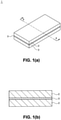
1 zeigt eine perspektivische Außenansicht eines nicht erfindungsgemäßen schallabsorbierenden Materials und dessen Querschnittsansicht.1 Fig. 12 shows an external perspective view of a sound absorbing material not according to the invention and its cross-sectional view. -
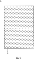
2 ist eine Draufsicht auf einen zweiten Vliesstoff und zeigt die Form von Fixierungsabschnitten in dieser Ausführungsform.2 Fig. 14 is a plan view of a second nonwoven fabric, showing the shape of fixing portions in this embodiment. -
3 ist ein Diagramm, das vorstellbare Formmuster der Fixierungsabschnitte zeigt.3 Fig. 14 is a diagram showing conceivable shape patterns of the fixing portions. -
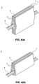
4 zeigt eine perspektivische Außenansicht eines mit dem schallabsorbierenden Material versehenen erfindungsgemäßen Kabelbaums.4 shows an external perspective view of a wire harness provided with the sound absorbing material according to the invention. -
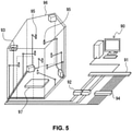
5 ist ein Diagramm, das eine Messvorrichtung illustriert, die beim Prüfen von Schallabsorptionskoeffizienten in einem Hallraum verwendet wird.5 14 is a diagram illustrating a measuring device used in checking sound absorption coefficients in a reverberation room. -
6 ist ein Graph, der die Prüfergebnisse für Schallabsorptionskoeffizienten in einem Hallraum zeigt.6 Fig. 12 is a graph showing test results for sound absorption coefficients in a reverberation room.
Beschreibung von AusführungsformenDescription of Embodiments
Nachfolgend wird eine Ausführungsform der vorliegenden Erfindung ausführlich mit Bezug auf die Zeichnungen beschrieben.
Das schallabsorbierende Material 1 der vorliegenden Ausführungsform ist ein gestapelter Vliesstoff, gebildet aus zwei ersten Vliesstoffen 2, die in ihrer Dickenrichtung gestapelt sind, und einem zweiten Vliesstoff 3, der dazwischen angeordnet ist. Die ersten Vliesstoffe 2 und der zweite Vliesstoff 3 sind integriert, indem ihre gegenüberliegenden Oberflächen mit einer thermisch schmelzbaren Folie zusammengeklebt sind. Das Verfahren zum Verbinden der ersten Vliesstoffe 2 und des zweiten Vliesstoffs 3 ist nicht auf thermisch schmelzbare Folien begrenzt, und es können auch Vernadelungen, Heftungen oder dergleichen verwendet werden.The
Außerdem ist das schallabsorbierende Material 1 auf eine Luftströmungsgeschwindigkeit von 5 bis 50 cm3/cm2•s eingestellt. Es wird angemerkt, dass bei der vorliegenden Erfindung „Luftströmungsgeschwindigkeit“ einen Wert bezeichnet, der „per ‚Frazier-Luftdurchlässigkeitsprüfung‘ in 8. 26. 1A in der JIS L 1096, ‚Prüfverfahren für gewebte und gestrickte Stoffe‘, gemessen“ ist. Die Frazier-Luftdurchlässigkeitsprüfung ist durch Messen von Luftströmungsgeschwindigkeiten mit einem handelsüblichen Frazier-Prüfgerät durchführbar.In addition, the
Die Fasern in den Fixierungsabschnitten 31 sind durch Pressen und Erwärmen mit der Prägewalze stark verbunden und in einem Zustand geschmolzen und verfestigt, in dem die Fasern miteinander in engem Kontakt stehen. Bei einer solchen Faserstruktur weisen die Fixierungsabschnitte 31 hohe Zugfestigkeit auf, da die Verschlingung der Fasern sich auch dann nicht leicht löst, wenn eine Zugbeanspruchung darauf angewandt wird. Da der zweite Vliesstoff 3 aus langstapeligen Fasern hergestellt ist, wird zudem die Zugfestigkeit der Fixierungsabschnitte 31 auch in einem anderen Bereich als den Fixierungsabschnitten 31 verbessert.The fibers in the fixing
Es wird angemerkt, dass die Fixierungsabschnitte 31 in der vorliegenden Ausführungsform mittels der Prägewalze gebildet sind und dass dieses Verfahren gewählt wird, weil der zweite Vliesstoff 3 ein dünner folienförmiger Vliesstoff ist und dieses Verfahren auch dann nur geringe Wirkung auf dessen Dicke hat, wenn der zweite Vliesstoff 3 die Prägewalze passiert, und der zweite Vliesstoff 3 in relativ kurzer Zeit mittels einer gewöhnlichen Prägevorrichtung verarbeitet werden kann. Das Verfahren zum Bilden der Fixierungsabschnitte 31 ist nicht auf thermisches Verschmelzen mit einer Prägewalze begrenzt, und es können auch ein Klebstoff, Ultraschallschweißen oder dergleichen verwendet werden. Diese Bildungsverfahren können gegebenenfalls entsprechend der Dicke des zweiten Vliesstoffs 3, der Art und der Eigenschaften der Faserbestandteile ausgewählt werden.It is noted that the fixing
Obwohl die rautenförmigen Fixierungsabschnitte 31 in der vorliegenden Ausführungsform in vorbestimmten Abständen über die gesamte obere Oberfläche des zweiten Vliesstoffs 3 vorgesehen sind, ist die Form der Fixierungsabschnitte 31 außerdem nicht auf eine Punktform wie in der vorliegenden Ausführungsform begrenzt; wie in
Die Fixierungsabschnitte 31 haben eine Ausbildung zur Erhöhung der Zugfestigkeit des zweiten Vliesstoffs 3 und dementsprechend zur Erhöhung der Zugfestigkeit des schallabsorbierenden Materials 1, bei dem es sich um den gestapelten Vliesstoff einschließlich des zweiten Vliesstoffs 3 handelt. Wenn die gesamte Oberfläche des zweiten Vliesstoffs 3 dazu gestaltet wäre, als Fixierungsabschnitte 31 zu dienen, könnte natürlich die höchste Zugfestigkeit erzielt werden, jedoch wäre die Luftströmungsgeschwindigkeit des zweiten Vliesstoffs 3 unzureichend, und die Schallabsorptionsleistung des schallabsorbierenden Materials 1 würde sich verringern.The fixing
Bei der Befestigung des schallabsorbierenden Materials 1 im Fahrzeug wird außerdem mit einer Zugbeanspruchung von circa 10 N/25 mm auf dem schallabsorbierenden Material 1 gerechnet. Die Fixierungsabschnitte 31 in der vorliegenden Ausführungsform sind über circa 25% der Oberflächengröße des zweiten Vliesstoffs 3 gebildet, und dementsprechend beträgt die Zugfestigkeit in einer zu der Dickenrichtung des schallabsorbierenden Materials 1 senkrechten Richtung mindestens 10 N/25 mm.When fastening the sound-absorbing
Die bevorzugte Form und das bevorzugte Anordnungsmuster der Fixierungsabschnitte 31 in dem zweiten Vliesstoff 3 sowie das bevorzugte Verhältnis der Fixierungsabschnitte 31 zur Oberflächengröße sind abhängig von der Faserlänge der Faserbestandteile des zweiten Vliesstoffs 3, Fasertyp und -eigenschaften sowie der Zugfestigkeit der ersten Vliesstoffe 2. Diese Kombinationen müssen in einem solchen Bereich eingestellt sein, dass die Gesamtzugfestigkeit des schallabsorbierenden Materials 1 einschließlich des zweiten Vliesstoffs 3 mindestens 10 N/25 mm beträgt und die Luftströmungsgeschwindigkeit des schallabsorbierenden Materials 1 von 5 bis 50 cm3/cm2 •s beträgt.The preferred shape and the preferred arrangement pattern of the fixing
Es ist wünschenswert, dass das Flächengewicht des ersten Vliesstoffs 2 im Bereich von 100 bis 1000 g/m2 und seine Dicke im Bereich von 1,0 bis 50,0 mm liegt. Bei einer Erhöhung des Flächengewichtes erhöhen sich tendenziell die Schallabsorptionskoeffizienten in allen Frequenzbändern, während sich bei einer Verringerung des Flächengewichtes die Schallabsorptionskoeffizienten in allen Frequenzbändern tendenziell verringern. Außerdem erhöht sich bei einer Erhöhung der Dicke tendenziell die Schallabsorptionsleistung in niedrigen Frequenzbändern, während sich bei einer Verringerung der Dicke die Schallabsorptionseigenschaften in hohen Frequenzbändern tendenziell erhöhen. Die Dicke des ersten Vliesstoffs 2 kann entsprechend dem zu absorbierenden Frequenzband in geeigneter Weise eingestellt sein.It is desirable that the basis weight of the first
Es ist wünschenswert, dass das Flächengewicht des zweiten Vliesstoffs 3 im Bereich von 10 bis 400 g/m2 liegt und seine Dicke im Bereich von 0,1 bis 4,0 mm liegt. Durch kleinere Gestaltung der Dicke des zweiten Vliesstoffs 3 als derjenigen des ersten Vliesstoffs 2 hat der zweite Vliesstoff 3 bessere Schallabsorptionseigenschaften in hohen Frequenzbereichen als der erste Vliesstoff 2 und kann Geräusch in breiteren Frequenzbändern absorbieren. Wenn jedoch sein Flächengewicht und seine Dicke unterhalb der oben beschriebenen Bereiche liegen, besteht die Gefahr, dass die Schallabsorptionswirkungen des zweiten Vliesstoffs 3 als des schallabsorbierenden Materials nicht ausreichend auftreten. In der vorliegenden Ausführungsform wird als zweiter Vliesstoff 3 ein dünner folienförmiger Vliesstoff mit geringerer Dicke als bei dem ersten Vliesstoff 2 verwendet, und die Fixierungsabschnitte 31 sind auf dem zweiten Vliesstoff 3 mit der Prägewalze bereitgestellt, und somit wird die Zugfestigkeit erhöht, ohne dass die ursprüngliche Schallabsorptionsleistung des schallabsorbierenden Materials 1 im Bereich von niedrigen Frequenzen bis zu hohen Frequenzen beeinträchtigt wird.It is desirable that the basis weight of the second
Ein Faserdurchmesser des zweiten Vliesstoffs 3 liegt günstigerweise im Bereich von 1 bis 50 µm, und ein Faserdurchmesser des ersten Vliesstoffs 2 liegt günstigerweise im Bereich von 4 bis 100 µm. Obwohl ein Vliesstoff mit schmalem Faserdurchmesser, der als der Vliesstoff verwendet wird, hohe Schallabsorptionsleistung hat, besteht bei zu schmalem Faserdurchmesser die Gefahr, dass der Vliesstoff reißanfällig wird.A fiber diameter of the second
Beispiele für ein Fasermaterial, das für den ersten Vliesstoff 2 und den zweiten Vliesstoff 3 verwendet werden kann, sind unter anderem Polyester wie etwa Polyethylenterephthalat und Polybutylenterephthalat, Polyolefine, Nylon, Polyamid, Polyvinylchlorid, Viscose, Acryl, Acrylnitril, Cellulose, Kenaf und Glas.Examples of a fiber material that can be used for the first
Als Fertigungsverfahren für den ersten Vliesstoff 2 und den zweiten Vliesstoff 3 können Spinnvliesverfahren, Wasserstrahlverfestigung, Nadeln, Schmelzspinnen und dergleichen mehr verwendet werden.As manufacturing methods for the first
Die Querschnittsform des ersten Vliesstoffs 2 und des zweiten Vliesstoffs 3 unterliegt keiner besonderen Einschränkung; verwendbar sind Kern-Mantel-Fasern, zylindrische Fasern, Hohlfasern, Seite-an-Seite-Fasern und andere Fasern mit modifizierten Querschnittsformen, die sich von denen gewöhnlicher Fasern unterscheiden.The cross-sectional shape of the first
Beispiele für den Kabelbaum 4 sind unter anderem ein Kabelbaum, der durch Bündeln mehrerer elektrischer Leitungen gewonnen ist, die durch Beschichten eines Leitungskerns mit einem Isolator gewonnen sind, und ein Kabelbaum, der nur aus einer einzelnen elektrischen Leitung gebildet ist.Examples of the
Durch sandwichartige Anordnung und Bedeckung eines Abschnitts des Kabelbaums 4 dient das schallabsorbierende Material 1 nicht nur als das schallabsorbierende Material, sondern auch als Puffermaterial für den Kabelbaum 4.By sandwiching and covering a portion of the
Ausführungsbeispieleexemplary embodiments
ZugfestigkeitsprüfungTensile Strength Test
Nachfolgend werden ein Verfahren für eine Zugfestigkeitsprüfung, die an dem schallabsorbierenden Material der vorliegenden Erfindung durchgeführt wurde, und deren Ergebnisse beschrieben.A method for a tensile strength test performed on the sound absorbing material of the present invention and its results will be described below.
Der in der Zugfestigkeitsprüfung verwendete erste und zweite Vliesstoff haben folgende Spezifikationen. Zum Vergleich wurden zweite Vliesstoffe mit einem Flächengewicht von 50 g/m2, 20 g/m2 und 10 g/m2 hergestellt, und es wurden zweite Vliesstoffe mit oberen Oberflächen, die mit rautenförmigen Fixierungsabschnitten versehen waren, sowie zweite Vliesstoffe mit oberen Oberflächen ohne Fixierungsabschnitte hergestellt. Die schallabsorbierenden Materialien der Ausführungsbeispiele und der Vergleichsbeispiele wurden hergestellt, indem ein zweiter Vliesstoff sandwichartig zwischen zwei ersten Vliesstoffen angeordnet und der zweite Vliesstoff mithilfe einer thermisch schmelzbaren Folie mit denselben verbunden wurde, dazu wurden schallabsorbierende Materialien ohne den zweiten Vliesstoff gewonnen, indem nur zwei erste Vliesstoffe mithilfe einer thermisch schmelzbaren Folie verbunden wurden.The first and second non-woven fabrics used in the tensile strength test have the following specifications. For comparison, second nonwoven fabrics having basis weights of 50 g/m 2 , 20 g/m 2 and 10 g/m 2 were prepared, and second nonwoven fabrics having top surfaces provided with diamond-shaped fixing portions and second nonwoven fabrics having top surfaces were made made without fixation sections. The sound absorbing materials of the working examples and the comparative examples were prepared by sandwiching a second non-woven fabric between two first non-woven fabrics and bonding the second non-woven fabric to them using a thermally fusible film, and sound-absorbing materials without the second non-woven fabric were obtained by using only two first non-woven fabrics connected using a thermally fusible foil.
Erster VliesstoffFirst fleece
Fasermaterial: kurzstapelige PET-Faser (Faserlänge: circa 51 mm) Flächengewicht: 300 g/m2
Dicke: 10 mmFiber material: short-staple PET fibers (fiber length: approx. 51 mm) basis weight: 300 g/m 2
Thickness: 10mm
Zweiter VliesstoffSecond non-woven fabric
Fasermaterial: langstapelige PET-FaserFiber Material: PET Long Staple Fiber
Flächengewicht: 50 g/m2, 20 g/m2 und 10 g/m2 Basis weight: 50 g/m 2 , 20 g/m 2 and 10 g/m 2
Dicke: 0,5 mmThickness: 0.5mm
Die Zugfestigkeit wurde entsprechend dem Prüfverfahren für „Zugfestigkeit und Dehnung“ in der JIS L1913 gemessen. Die Größe der Probestücke betrug 25 mm × 100 mm, und 20 mm an beiden Enden in ihrer Längsrichtung wurden mit Spannvorrichtungen gehalten. Die Zuggeschwindigkeit war auf 100 mm/min eingestellt, und die maximale Zugfestigkeit wurde bestimmt. Außerdem waren als Prüfung für die Befestigung der Probestücke an einem Fahrzeug die Probestücke jeweils in einem Zustand fixiert, in dem eine Seite des Probestücks heruntergedrückt wurde, das Probestück gezogen wurde und die andere Seite fixiert war, und die Probestücke, die dabei rissen, wurden mit „ד bewertet sowie die Probestücke ohne Defekte mit „O“ bewertet. Die Ergebnisse der oben beschriebenen Prüfungen sind in Tabelle 1 gezeigt. Tabelle 1
Die oben beschriebenen Prüfergebnisse zeigen, dass durch Versehen des zweiten Vliesstoffs mit Fixierungsabschnitten die Zugfestigkeit des schallabsorbierenden Materials erhöht wurde und auch bei einer Verringerung des Flächengewichts des zweiten Vliesstoffs auf 10 g/m2 eine Zugfestigkeit von 10 N/25 mm gewährleistet war. Außerdem zeigen sie, dass das schallabsorbierende Material mit einer Zugfestigkeit von 10 N/25 mm auch dann nicht riss, wenn eine Zugbeanspruchung äquivalent zu der Beanspruchung darauf ausgeübt wurde, die bei Befestigung des schallabsorbierenden Materials an einem Fahrzeug ausgeübt wird.The test results described above show that by providing the second nonwoven fabric with fixing sections, the tensile strength of the sound absorbing material was increased and a tensile strength of 10 N/25 mm was ensured even when the basis weight of the second nonwoven fabric was reduced to 10 g/m 2 . In addition, they show that the sound absorbing material having a tensile strength of 10N/25mm did not crack even when a tensile stress equivalent to that applied when the sound absorbing material was fixed to a vehicle was applied thereto.
Prüfung der SchallabsorptionsleistungSound absorption performance test
Nachfolgend wird ein Verfahren zur Prüfung der Schallabsorptionsleistung, das an dem schallabsorbierenden Material der vorliegenden Erfindung durchgeführt wurde, und sein Ergebnis beschrieben.A sound absorbing performance testing method performed on the sound absorbing material of the present invention and its result will be described below.
Der in der Prüfung der Schallabsorptionsleistung verwendete erste und zweite Vliesstoff haben folgende Spezifikationen. Es wurden schallabsorbierende Materialien der Ausführungsbeispiele und der Vergleichsbeispiele verwendet, die durch Stapeln von zwei ersten Vliesstoffen und zwei zweiten Vliesstoffen in der Dickenrichtung gewonnen waren (erster Vliesstoff / zweiter Vliesstoff / erster Vliesstoff / zweiter Vliesstoff).The first and second non-woven fabrics used in the sound absorption performance test have the following specifications. The sound absorbing materials of the working examples and the comparative examples obtained by stacking two first nonwoven fabrics and two second nonwoven fabrics in the thickness direction (first nonwoven fabric/second nonwoven fabric/first nonwoven fabric/second nonwoven fabric) were used.
Erster VliesstoffFirst fleece
Fasermaterial: kurzstapelige PET-Faser (Faserlänge: circa 51 mm) Flächengewicht: 300 g/m2 Fiber material: short-staple PET fibers (fiber length: approx. 51 mm) basis weight: 300 g/m 2
Dicke: 10 mmThickness: 10mm
Zweiter VliesstoffSecond non-woven fabric
Fasermaterial: langstapelige PET-FaserFiber Material: PET Long Staple Fiber
Luftströmungsgeschwindigkeit: 5 bis 60 cm3/cm2 •sAir flow rate: 5 to 60 cm 3 /cm 2 •s
Die Luftströmungsgeschwindigkeiten der zweiten Vliesstoffe, die in den Ausführungsbeispielen und den Vergleichsbeispielen verwendet wurden, sind folgende. Die Messung der unten angegebenen Luftströmungsgeschwindigkeiten erfolgte entsprechend dem „Frazier-Luftdurchlässigkeitsprüfungs“-Verfahren in 8. 26. 1A in der JIS L 1096, „Prüfverfahren für gewebte und gestrickte Stoffe“.
Ausführungsbeispiel 2-1: 5 cm3/cm2 •s
Ausführungsbeispiel 2-2: 25 cm3/cm2 •s
Ausführungsbeispiel 2-3: 50 cm3/cm2 •s
Vergleichsbeispiel 2-1: 2 cm3/cm2 •s
Vergleichsbeispiel 2-2: 60 cm3/cm2•sThe air flow velocities of the second non-woven fabrics used in the working examples and the comparative examples are as follows. The measurement of the air flow velocities given below was carried out according to the "Frazier air permeability test" method in 8.26.1A in JIS L 1096, "Test methods for woven and knitted fabrics".
Embodiment 2-1: 5 cm 3 /cm 2 ·s
Embodiment 2-2: 25 cm 3 /cm 2 ·s
Example 2-3: 50 cm 3 /cm 2 ·s
Comparative Example 2-1: 2 cm 3 /cm 2 •s
Comparative Example 2-2: 60 cm 3 /cm 2 •s
Die Schallabsorptionskoeffizienten der schallabsorbierenden Materialien aus den oben beschriebenen Ausführungsbeispielen und Vergleichsbeispielen wurden in einem Hallraum gemessen, und ihre Schallabsorptionsleistung wurde bewertet. Ein spezifisches Prüfverfahren für Schallabsorptionskoeffizienten in einem Hallraum ist folgendes. Die Prüfergebnisse für Schallabsorptionskoeffizienten im Hallraum sind in Tabelle 2 und
Die Prüfung der Schallabsorptionskoeffizienten erfolgte entsprechend dem „Messverfahren für Schallabsorptionskoeffizienten in einem Hallraum“ in der JIS A 1409, und die Schallabsorptionskoeffizienten wurden mit der unten angegebenen Gleichung (1) gewonnen. Wie in
![]()
- S:
- Fläche der Probe (m2)
- A:
- äquivalenter Schallabsorptionsbereich (m2), gewonnen mit der unten angegebenen Gleichung (2)
V: Volumen (m3) des Hallraums in einem Zustand ohne darin angeordnete Proben
c: Schallgeschwindigkeit in der Luft (m/s)
T1: Nachhallzeit (s) im Hallraum in einem Zustand ohne darin angeordnete Proben
T2: Nachhallzeit (s) im Hallraum in einem Zustand mit einer darin angeordneten
- S:
- Sample area (m 2 )
- A:
- equivalent sound absorption area (m 2 ) obtained with equation (2) given below
V: Volume (m 3 ) of the reverberation room in a state with no samples placed therein
c: speed of sound in air (m/s)
T1: Reverberation time (s) in the reverberation room in a state with no samples placed therein
T2: reverberation time (s) in the reverberation room in a state with a sample placed therein Table 2
Die Prüfergebnisse in Tabelle 2 und
Die oben beschriebenen Prüfungen zeigen, dass sowohl die Schallabsorptionsleistung als auch die Zugfestigkeit des schallabsorbierenden Materials erhöht wurden, indem die Fixierungsabschnitte an dem zweiten Vliesstoff vorgesehen wurden, während die Luftströmungsgeschwindigkeit des schallabsorbierenden Materials im Bereich von 5 bis 50 cm3/cm2 •s eingestellt wurde.The tests described above show that both the sound absorbing performance and the tensile strength of the sound absorbing material were increased by providing the fixing portions to the second non-woven fabric while adjusting the air flow speed of the sound absorbing material in the range of 5 to 50 cm 3 /cm 2 ·s would.
Vorangehend wurden zwar eine Ausführungsform, Ausführungsbeispiele und Vergleichsbeispiele der vorliegenden Erfindung ausführlich beschrieben, jedoch ist die vorliegende Erfindung nicht lediglich auf die oben beschriebene Ausführungsform oder dergleichen beschränkt, und es wird darauf hingewiesen, dass verschiedene Abwandlungen vorgenommen werden können, ohne von dem Wesentlichen der vorliegenden Erfindung abzuweichen.Although an embodiment, working examples and comparative examples of the present invention have been described in detail above, the present invention is not limited only to the above-described embodiment or the like, and it is noted that various modifications can be made without departing from the gist of the present invention deviate from the invention.
Claims (6)
Applications Claiming Priority (3)
| Application Number | Priority Date | Filing Date | Title |
|---|---|---|---|
| JP2015016941A JP6447189B2 (en) | 2015-01-30 | 2015-01-30 | Sound absorbing material and wire harness with sound absorbing material |
| JP2015-016941 | 2015-01-30 | ||
| PCT/JP2016/050588 WO2016121468A1 (en) | 2015-01-30 | 2016-01-09 | Sound-absorbing material, and wiring harness with sound-absorbing material |
Publications (2)
| Publication Number | Publication Date |
|---|---|
| DE112016000552T5 DE112016000552T5 (en) | 2017-11-02 |
| DE112016000552B4 true DE112016000552B4 (en) | 2022-01-20 |
Family
ID=56543088
Family Applications (1)
| Application Number | Title | Priority Date | Filing Date |
|---|---|---|---|
| DE112016000552.0T Active DE112016000552B4 (en) | 2015-01-30 | 2016-01-09 | Wiring harness provided with sound-absorbing material |
Country Status (5)
| Country | Link |
|---|---|
| US (1) | US10583627B2 (en) |
| JP (1) | JP6447189B2 (en) |
| CN (1) | CN107251135B (en) |
| DE (1) | DE112016000552B4 (en) |
| WO (1) | WO2016121468A1 (en) |
Families Citing this family (5)
| Publication number | Priority date | Publication date | Assignee | Title |
|---|---|---|---|---|
| EP3663083A1 (en) * | 2017-07-31 | 2020-06-10 | JNC Corporation | Laminated acoustic absorption member |
| JP6852725B2 (en) | 2018-11-26 | 2021-03-31 | 日立金属株式会社 | Cables and harnesses |
| EP3957478B1 (en) * | 2019-04-16 | 2023-10-18 | Denka Company Limited | Binding tape |
| US20220325141A1 (en) * | 2019-09-19 | 2022-10-13 | Denka Company Limited | Binding tape |
| JP7817224B2 (en) * | 2023-11-14 | 2026-02-18 | 矢崎総業株式会社 | Wire harness routing structure |
Citations (6)
| Publication number | Priority date | Publication date | Assignee | Title |
|---|---|---|---|---|
| US4111081A (en) | 1976-01-02 | 1978-09-05 | The Boeing Company | Low non-linearity factor sound attenuating laminate |
| US20040077247A1 (en) | 2002-10-22 | 2004-04-22 | Schmidt Richard J. | Lofty spunbond nonwoven laminate |
| JP2004143632A (en) | 2002-10-25 | 2004-05-20 | Toray Ind Inc | Sound absorbing material |
| JP2008068799A (en) | 2006-09-15 | 2008-03-27 | Teijin Fibers Ltd | Sound absorber and vehicular floor sheet |
| JP2011084855A (en) | 2009-09-15 | 2011-04-28 | Nagoya Oil Chem Co Ltd | Heat adhesive nonwoven fabric, sound absorption fiber sheet, and sound absorption material |
| DE112013006984T5 (en) | 2013-04-26 | 2016-01-28 | Autonetworks Technologies, Ltd. | Sound absorbing material and cabling equipped with a sound absorbing material |
Family Cites Families (15)
| Publication number | Priority date | Publication date | Assignee | Title |
|---|---|---|---|---|
| JP4361201B2 (en) * | 2000-09-05 | 2009-11-11 | 株式会社クラレ | Sound-absorbing material including meltblown nonwoven fabric |
| US7320739B2 (en) * | 2003-01-02 | 2008-01-22 | 3M Innovative Properties Company | Sound absorptive multilayer composite |
| KR100743751B1 (en) * | 2003-04-22 | 2007-07-27 | 아사히 가세이 셍이 가부시키가이샤 | High Strength Non-woven Fabric |
| US20070269632A1 (en) * | 2003-11-27 | 2007-11-22 | Yoshihiko Ota | Sound Absorbing Material |
| JP2005263118A (en) * | 2004-03-19 | 2005-09-29 | Howa Seni Kogyo Kk | Sound absorbing material for vehicle |
| JP4120883B2 (en) * | 2004-06-29 | 2008-07-16 | 東洋紡績株式会社 | Spunbond nonwoven fabric |
| JP2006039379A (en) * | 2004-07-29 | 2006-02-09 | Nishikawa Rubber Co Ltd | Sound insulation sheet |
| JP4626969B2 (en) * | 2004-12-10 | 2011-02-09 | 呉羽テック株式会社 | Vehicle interior material with excellent sound absorption performance |
| CN102144058B (en) * | 2008-09-04 | 2012-07-11 | 大和纺控股株式会社 | Fibrous mass, composite of conductive substrate with fibrous mass, and processes for producing same |
| JP2010128005A (en) * | 2008-11-25 | 2010-06-10 | Asahi Kasei Fibers Corp | Composite sound absorbing material |
| FR2942437B1 (en) * | 2009-02-20 | 2012-08-24 | Faurecia Automotive Ind | SOUNDPROOFING ASSEMBLY FOR MOTOR VEHICLE AND ASSOCIATED WALL ELEMENT. |
| US20110293892A1 (en) * | 2009-12-22 | 2011-12-01 | Masanori Ogawa | Heat-insulating and sound absorbing material for the heat-insulating and sound absorbing structure of a car body |
| US8496088B2 (en) * | 2011-11-09 | 2013-07-30 | Milliken & Company | Acoustic composite |
| US20140049071A1 (en) * | 2012-08-14 | 2014-02-20 | Caterpillar, Inc. | Sound Insulation Structure |
| JP6411018B2 (en) * | 2012-10-03 | 2018-10-24 | 矢崎総業株式会社 | Wire harness assembly structure |
-
2015
- 2015-01-30 JP JP2015016941A patent/JP6447189B2/en active Active
-
2016
- 2016-01-09 US US15/547,149 patent/US10583627B2/en active Active
- 2016-01-09 CN CN201680007335.3A patent/CN107251135B/en active Active
- 2016-01-09 DE DE112016000552.0T patent/DE112016000552B4/en active Active
- 2016-01-09 WO PCT/JP2016/050588 patent/WO2016121468A1/en not_active Ceased
Patent Citations (6)
| Publication number | Priority date | Publication date | Assignee | Title |
|---|---|---|---|---|
| US4111081A (en) | 1976-01-02 | 1978-09-05 | The Boeing Company | Low non-linearity factor sound attenuating laminate |
| US20040077247A1 (en) | 2002-10-22 | 2004-04-22 | Schmidt Richard J. | Lofty spunbond nonwoven laminate |
| JP2004143632A (en) | 2002-10-25 | 2004-05-20 | Toray Ind Inc | Sound absorbing material |
| JP2008068799A (en) | 2006-09-15 | 2008-03-27 | Teijin Fibers Ltd | Sound absorber and vehicular floor sheet |
| JP2011084855A (en) | 2009-09-15 | 2011-04-28 | Nagoya Oil Chem Co Ltd | Heat adhesive nonwoven fabric, sound absorption fiber sheet, and sound absorption material |
| DE112013006984T5 (en) | 2013-04-26 | 2016-01-28 | Autonetworks Technologies, Ltd. | Sound absorbing material and cabling equipped with a sound absorbing material |
Non-Patent Citations (2)
| Title |
|---|
| JP 2004- 143 632 A (Maschinenübersetzung), AIPN [online] JPO [abgerufen am 21.02.2018] |
| JP 2011- 084 855 A (Maschinenübersetzung), ESPACENET [online] EPO [abgerufen am 18.03.2020] |
Also Published As
| Publication number | Publication date |
|---|---|
| WO2016121468A1 (en) | 2016-08-04 |
| US10583627B2 (en) | 2020-03-10 |
| CN107251135B (en) | 2020-09-15 |
| CN107251135A (en) | 2017-10-13 |
| US20180022064A1 (en) | 2018-01-25 |
| JP6447189B2 (en) | 2019-01-09 |
| DE112016000552T5 (en) | 2017-11-02 |
| JP2016142831A (en) | 2016-08-08 |
Similar Documents
| Publication | Publication Date | Title |
|---|---|---|
| DE112016000552B4 (en) | Wiring harness provided with sound-absorbing material | |
| DE69607164T2 (en) | SOUND INSULATION METHOD AND SOUND INSULATION ITEM | |
| DE69400923T2 (en) | Soundproofing material | |
| DE112013006984B4 (en) | Wiring equipped with a soundproofing material | |
| EP1311640B1 (en) | Adhesive tapes comprising a textile support for enveloping elongated material, particularly looms of cables | |
| EP1644222B1 (en) | Acoustically effective wheel house covering for vehicles | |
| EP1060073B1 (en) | Laminate | |
| DE112015000560T5 (en) | Acoustic isolator and wiring with an acoustic isolator | |
| DE102011084168B4 (en) | Flexible shaft loudspeaker, motor vehicle with flexible shaft loudspeaker, and use of a flexible shaft loudspeaker | |
| DE102015212719A1 (en) | Multi-layered, sound-absorbing, sound-absorbing and air-permeable material | |
| DE112015000864B4 (en) | Use of a non-woven fabric as a muffler in a vehicle | |
| DE112014003852T5 (en) | Acoustic material and wiring with an acoustic material | |
| DE202013012568U1 (en) | Foam-type acoustic element of a vehicle body panel component | |
| DE4304628C2 (en) | Sound absorbing housing lining | |
| DE102004050649A1 (en) | Sound absorbing heat shield, comprises a sheet metal carrier, which holds an acoustic and thermally insulating layer | |
| EP2181226B1 (en) | Sound absorber | |
| DE19720537A1 (en) | Thermal insulation for sound absorbing elements etc. in cars | |
| EP2497807A1 (en) | Adhesive tape for bundling cables | |
| EP1927639B1 (en) | Technical non-woven adhesive tape | |
| DE112015000851T5 (en) | Wiring harness with a silencer | |
| EP1663717A1 (en) | Noise absorber for the engine compartment | |
| DE102005003994B4 (en) | Method for producing an acoustic absorber | |
| DE20218350U1 (en) | Material for production of a lining element for use in a motor vehicle comprises decorative, adhesive, carrier and sound absorber layers | |
| EP1741764B1 (en) | Self-winding adhesive tape and method for its manufacture | |
| DE102005036242B4 (en) | Molded part for covering a sound-generating or sound-reflecting component and sound-absorbing material structure |
Legal Events
| Date | Code | Title | Description |
|---|---|---|---|
| R012 | Request for examination validly filed | ||
| R083 | Amendment of/additions to inventor(s) | ||
| R016 | Response to examination communication | ||
| R018 | Grant decision by examination section/examining division | ||
| R020 | Patent grant now final |