GEBIET DER ERFINDUNGFIELD OF THE INVENTION
Vorliegende Erfindung betrifft ein Arbeitsfahrzeug und eine Rundumkennleuchte.The present invention relates to a work vehicle and a rotating beacon.
BESCHREIBUNG DES STANDES DER TECHNIKDESCRIPTION OF THE PRIOR ART
Manche Hydraulikbagger (Beispiel eines Arbeitsfahrzeugs) haben die Funktion eines mobilen Krans eines Typs mit abwinkelbarem Ausleger. Wenn mit einem Hydraulikbagger wie diesem Kranarbeiten durchgeführt werden, muss eine Rundumkennleuchte angebracht werden, die aufblinken kann. Die Rundumkennleuchte ist auf dem Kabinendach angeordnet, wie zum Beispiel in 1 von Patentliteratur 1 dargestellt.Some hydraulic excavators (example of a work vehicle) have the function of an articulated boom type mobile crane. When carrying out crane work with a hydraulic excavator such as this, a rotating beacon must be able to be flashing. The rotating beacon is arranged on the cabin roof, such as in 1 represented by Patent Literature 1.
DOKUMENTLISTEDOCUMENT LIST
PATENTLITERATURPatent Literature
-
Patentliteratur 1: Offengelegte japanische Patentanmeldungs-Publikation Nr. 2005-68830 Patent Literature 1: Disclosed Japanese Patent Application Publication No. 2005-68830
ÜBERSICHTOVERVIEW
PROBLEMSTELLUNGPROBLEM
Bei den vorgenannten üblichen Arbeitsfahrzeugen haben sich dabei jedoch die folgenden Probleme ergeben. Je nach Kabinenhöhe des Hydraulikbaggers wird gegebenenfalls die Transporthöhe überschritten, wenn die Rundumkennleuchte auf dem Kabinendach installiert ist. Sollte dies der Fall sein, muss die Rundumkennleuchte vor dem Transport abgenommen und vor Beginn der Arbeiten wieder angebracht werden. Aus diesem Grund wird eine Rundumkennleuchte benötigt, die sich einfacher abnehmen und wieder anbringen lässt. In the above-mentioned usual work vehicles, however, the following problems have resulted. Depending on the cabin height of the hydraulic excavator, the transport height may be exceeded if the rotating beacon is installed on the cab roof. If this is the case, the rotating beacon must be removed before transport and re-attached before starting work. For this reason, a rotating beacon is required, which is easier to remove and re-attach.
Es ist Aufgabe der vorliegenden Erfindung, eine Rundumkennleuchte, die leichter abzunehmen und wieder anzubringen ist, und ein mit einer Rundumkennleuchte ausgestattetes Arbeitsfahrzeug anzugeben.It is an object of the present invention to provide a Rundumkennleuchte, which is easier to remove and re-attach, and specify a equipped with a rotating beacon work vehicle.
PROBLEMLÖSUNGTROUBLESHOOTING
Das Arbeitsfahrzeug gemäß einem ersten Aspekt der Erfindung ist ein Arbeitsfahrzeug, das mit einem Arbeitsgerät ausgestattet ist, eine Kabine und eine Rundumkennleuchte hat. Die Kabine hat in ihrem oberen Bereich ein Dach, und rechts und links sind eine erste Seitenfläche und eine zweite Seitenfläche vorgesehen. Die Rundumkennleuchte ist abnehmbar auf dem Dach angeordnet. Die Rundumkennleuchte hat einen Rundumkennleuchten-Hauptkörper, ein Befestigungselement und einen Griff. Das Befestigungselement ist an der Unterseite des Rundumkennleuchten-Hauptkörpers vorgesehen und wird für die Befestigung des Rundumkennleuchten-Hauptkörpers an dem Dach verwendet. Der Griff ist portalförmig und ist an dem Befestigungselement festgelegt. Der Griff hat einen ersten stangenförmigen Abschnitt, einen zweiten stangenförmigen Abschnitt und einen dritten stangenförmigen Abschnitt. Der erste stangenförmige Abschnitt und der zweite stangenförmige Abschnitt sind von dem Befestigungselement nach oben weisend ausgebildet. Der erste stangenförmige Abschnitt liegt vor dem zweiten stangenförmigen Abschnitt. Der zweite stangenförmige Abschnitt ist zur Rückseite des Rundumkennleuchten-Hauptkörpers angeordnet und mehr zur Seite der ersten Seitenfläche als der erste stangenförmige Abschnitt. Der dritte stangenförmige Abschnitt ist bei Betrachtung von der Seite und senkrecht zur Längsrichtung über dem Rundumkennleuchten-Hauptkörper angeordnet.The work vehicle according to a first aspect of the invention is a work vehicle equipped with an implement having a cab and a rotating beacon. The cabin has a roof in its upper area, and right and left have a first side surface and a second side surface. The rotating beacon is removably mounted on the roof. The rotating beacon has a beacon main body, a fastener and a handle. The fastener is provided on the underside of the beacon main body and is used for attaching the beacon main body to the roof. The handle is portal-shaped and fixed to the fastener. The handle has a first rod-shaped portion, a second rod-shaped portion, and a third rod-shaped portion. The first rod-shaped portion and the second rod-shaped portion are formed by the fastener facing upward. The first rod-shaped portion lies in front of the second rod-shaped portion. The second rod-shaped portion is disposed toward the rear of the beacon main body and more toward the first side surface than the first rod-shaped portion. The third bar-shaped portion is located above the surround beacon main body when viewed from the side and perpendicular to the longitudinal direction.
Da das Dach hoch liegt, hält sich die Bedienungsperson bei der Befestigung der Rundumkennleuchte auf dem Kabinendach mit einer Hand an dem Dach fest und benutzt die andere Hand zum Befestigen der Rundumkennleuchte. Dabei umgreift die Bedienungsperson den ersten stangenförmigen Abschnitt oder den zweiten stangenförmigen Abschnitt, die nach oben weisend ausgebildet sind, wodurch es einfach ist, auf die Rundumkennleuchte eine Kraft in Richtung nach oben und nach unten auszuüben. Auf diese Weise lässt sich verhindern, dass die Rundumkennleuchte in Richtung nach oben und nach unten wackelt, auch wenn sie nur mit einer Hand auf dem Dach befestigt wird, und das Anbringen und Abnehmen gestaltet sich einfach. Since the roof is high, the operator holds with the fixing of the rotating beacon on the car roof with one hand to the roof and uses the other hand to attach the rotating beacon. In this case, the operator engages around the first rod-shaped portion or the second rod-shaped portion, which are formed facing upwards, whereby it is easy to exert a force on the rotating beacon in an upward and downward direction. In this way, it is possible to prevent the rotating beacon from wobbling upwards and downwards, even if it is fastened to the roof with only one hand, and attachment and detachment are simple.
Da der dritte stangenförmige Abschnitt des Griffes höher als der Rundumkennleuchten-Hauptkörper angeordnet ist, wird durch den dritten stangenförmigen Abschnitt auch weniger von dem Licht abgeblockt, das von der Rundumkennleuchte ausgestrahlt wird. Since the third bar-shaped portion of the handle is positioned higher than the rotating beacon main body, the third bar-shaped portion also blocks less of the light emitted from the rotating beacon.
Da der Griff überdies portalförmig ist, kann beim Abnehmen der Rundumkennleuchte von der Kabine der dritte stangenförmige Bereich umgriffen werden, wodurch sich die Leuchte auch besser tragen lässt.In addition, since the handle is portal-shaped, the third bar-shaped area can be encompassed when removing the rotating beacon from the cabin, whereby the lamp can also be better worn.
Die Stabilität wird durch die Portalform des Griffes ebenfalls verbessert.The stability is also improved by the portal shape of the handle.
Da der zweite stangenförmige Abschnitt zur Rückseite des Rundumkennleuchten-Hauptkörpers angeordnet ist, lässt sich außerdem vermeiden, dass Objekte von der Rückseite mit dem Rundumkennleuchten-Hauptkörper kollidieren. In addition, since the second rod-shaped portion is located toward the rear of the beacon main body, objects from the rear side can be prevented from colliding with the beacon main body.
Das Arbeitsfahrzeug gemäß dem zweiten Aspekt der Erfindung ist das Arbeitsfahrzeug gemäß dem ersten Aspekt, wobei ein Teil des dritten stangenförmigen Abschnitts in Draufsicht mit dem Rundumkennleuchten-Hauptkörper überlagert ist. The work vehicle according to the second aspect of the invention is the work vehicle according to the first aspect, wherein a part of the third rod-shaped portion is superimposed in plan view with the rotating beacon main body.
Die Ausbildung des Griffes derart, dass der Griff den Rundumkennleuchten-Hauptkörper überspannt, ermöglicht eine Anordnung des ersten stangenförmigen Abschnitts und des zweiten stangenförmigen Abschnitts näher an dem Schwerpunkt der Rundumkennleuchte. Es ist daher einfacher für die Bedienungsperson zu verhindern, dass die Rundumkennleuchte in Richtung nach oben und nach unten wackelt.The formation of the grip such that the grip spans the rotating beacon main body allows arrangement of the first rod-shaped portion and the second rod-shaped portion closer to the center of gravity of the rotating beacon. It is therefore easier for the operator to prevent the rotating beacon from wobbling up and down.
Das Arbeitsfahrzeug gemäß dem dritten Aspekt der Erfindung ist das Arbeitsfahrzeug gemäß dem zweiten Aspekt der Erfindung, wobei ein Rundumkennleuchten-Hauptkörper ein Basiselement, eine Lichtquelle und ein Abdeckelement hat. Das Basiselement ist an dem Befestigungselement befestigt. Die Lichtquelle ist an der Innenseite des Basiselements angeordnet. Das Abdeckelement deckt die Lichtquelle von oben ab und ist abnehmbar an dem Basiselement befestigt. Ein bestimmter Spalt ist zwischen dem dritten stangenförmigen Abschnitt und dem Abdeckelement gebildet, damit das Abdeckelement hindurchtreten kann, wenn es von dem Basiselement entfernt wird.The work vehicle according to the third aspect of the invention is the work vehicle according to the second aspect of the invention, wherein a turn signal lamp main body has a base member, a light source, and a cover member. The base member is attached to the fastener. The light source is arranged on the inside of the base element. The cover member covers the light source from above and is detachably attached to the base member. A certain gap is formed between the third bar-shaped portion and the cover member to allow the cover member to pass when it is removed from the base member.
Durch den bestimmten Spalt, der zwischen dem dritten stangenförmigen Abschnitt und dem Abdeckelement gebildet ist, lässt sich das Abdeckelement ohne weiteres von dem Basiselement abnehmen und an dem Basiselement anbringen, auch wenn der Griff derart vorgesehen ist, dass dieser den Rundumkennleuchten-Hauptkörper umgibt. Das Auswechseln der Lichtquelle wird dadurch erleichtert.By the specific gap formed between the third bar-shaped portion and the cover member, the cover member can be easily detached from the base member and attached to the base member even if the handle is provided so as to surround the turn-signal lamp main body. The replacement of the light source is facilitated.
Das Arbeitsfahrzeug gemäß dem vierten Aspekt der Erfindung ist das Arbeitsfahrzeug gemäß dem ersten Aspekt, wobei das Arbeitsgerät auf/zu der Seite der ersten Seitenfläche der Kabine angeordnet ist. Die Rundumkennleuchte ist an dem Ende des Daches auf der Seite der zweiten Seitenfläche angeordnet. Der erste stangenförmige Abschnitt ist mehr zur Seite der zweiten Seitenfläche angeordnet als der Rundumkennleuchten-Hauptkörper. Ein Teil des ersten stangenförmigen Abschnitts ist von der Seite der zweiten Seitenfläche betrachtet mit dem Rundumkennleuchten-Hauptkörper überlagert. The work vehicle according to the fourth aspect of the invention is the work vehicle according to the first aspect, wherein the work implement is disposed on / to the side of the first side surface of the car. The Rundumkennleuchte is arranged at the end of the roof on the side of the second side surface. The first bar-shaped portion is located more to the second side surface side than the turn-signal main body. A part of the first rod-shaped portion is superposed with the beacon main body when viewed from the second side surface side.
Da die Rundumkennleuchte auf der dem Arbeitsgerät gegenüberliegenden Seite über der zweiten Seitenfläche der Kabine angeordnet ist, kann die Rundumkennleuchte von außerhalb des Arbeitsfahrzeugs angebracht werden, ohne dass die Bedienungsperson in das Arbeitsfahrzeug klettern muss. Since the rotating beacon is disposed on the opposite side of the implement on the second side surface of the cabin, the beacon can be mounted from outside the work vehicle without the operator having to climb into the work vehicle.
Da ein Teil des ersten stangenförmigen Abschnitts dem Rundumkennleuchten-Hauptkörper überlagert ist, kann der erste stangenförmige Abschnitt näher an dem Rundumkennleuchten-Hauptkörper angeordnet werden. Das heißt, da der erste stangenförmige Abschnitt näher am Schwerpunkt der Rundumkennleuchte angeordnet werden kann, ist es einfacher für die Bedienungsperson zu verhindern, dass die Rundumkennleuchte in Richtung nach oben und nach unten wackelt, wodurch die Anbringung der Rundumkennleuchte einfacher ist. Since a part of the first rod-shaped portion is superimposed on the rotating beacon main body, the first rod-shaped portion can be disposed closer to the beacon main body. That is, since the first rod-shaped portion can be located closer to the center of gravity of the rotating beacon, it is easier for the operator to prevent the beacon from wobbling upward and downward, making the beacon mounting easier.
Da ein Teil des ersten stangenförmigen Abschnitts mehr zur Seite der zweiten Seitenfläche angeordnet ist als der Rundumkennleuchten-Hauptkörper, lässt sich auch verhindern, dass Objekte von der Seite der zweiten Seitenfläche mit dem Rundumkennleuchten-Hauptkörper kollidieren. Also, since a part of the first rod-shaped portion is located more to the side of the second side surface than the beacon main body, it is possible to prevent objects from the side of the second side surface from colliding with the beacon main body.
Das Arbeitsfahrzeug gemäß dem fünften Aspekt der Erfindung ist das Arbeitsfahrzeug gemäß dem ersten Aspekt, ferner umfassend ein Basiselement, das an dem Dach befestigt ist und an dem das Befestigungselement lösbar festgelegt ist. Das Basiselement hat ein Eingriffselement und ein Führungselement. Das Eingriffselement ist geeignet für den Eingriff mit dem Befestigungselement. Das Führungselement führt das Befestigungselement in eine Position, in der es mit dem Eingriffselement in Eingriff gebracht werden kann, und hat einen Begrenzer. Der Begrenzer begrenzt die Bewegung des Befestigungselements in seinem in den Eingriff mit dem Eingriffselement geführten und gebrachten Zustand. Das Befestigungselement hat ein in Eingriff gebrachtes Element und ein begrenztes Element. Das in Eingriff gebrachte Element befindet sich im Eingriff mit dem Eingriffselement. Das begrenzte Element ist auf der gegenüberliegenden Seite des in Eingriff gebrachten Elements vorgesehen und flankiert den Rundumkennleuchten-Hauptkörper. In einem Zustand, in dem sich das Eingriffselement mit dem in Eingriff zu bringenden Element im Eingriff befindet, ist das in Eingriff gebrachte Element nach unten vorgespannt, und das begrenzte Element ist nach oben vorgespannt und trifft auf den Begrenzer, wodurch das Befestigungselement an dem Basiselement festgelegt wird.The work vehicle according to the fifth aspect of the invention is the work vehicle according to the first aspect, further comprising a base member fixed to the roof and to which the attachment member is detachably fixed. The base member has an engagement member and a guide member. The engagement element is suitable for engagement with the fastening element. The guide member guides the fastener to a position where it can be engaged with the engagement member and has a limiter. The limiter limits the movement of the fastener in its engaged and engaged condition with the engagement member. The fastener has an engaged element and a limited element. The engaged element is engaged with the engagement element. The limited element is provided on the opposite side of the engaged element and flanks the beacon main body. In a state in which the engagement member is engaged with the engageable member, the engaged member is biased downwardly and the constrained member is biased upward and strikes the limiter, thereby securing the attachment member to the base member is determined.
Es ist daher möglich, das Befestigungselement an dem Basiselement zu festzulegen, indem das Befestigungselement lediglich entlang des Führungselements in Anordnung gebracht und das Basiselement mit dem Befestigungselement in Eingriff gebracht wird. Die Rundumkennleuchte lässt sich entsprechend einfach an dem Dach befestigen. Ebenso einfach lässt sich die Rundumkennleuchte von dem Dach abnehmen, indem dieser Eingriff lediglich gelöst wird. It is therefore possible to fix the fastening element to the base element by arranging the fastening element only along the guide element and bringing the base element into engagement with the fastening element. The rotating beacon can be correspondingly easily attached to the roof. Just as easy to remove the rotating beacon from the roof by this intervention is only solved.
Das Arbeitsfahrzeug gemäß dem sechsten Aspekt der Erfindung ist das Arbeitsfahrzeug gemäß dem fünften Aspekt, wobei das Arbeitsgerät auf der Seite der ersten Seitenfläche der Kabine angeordnet ist. Die Rundumkennleuchte ist an dem Ende des Daches auf der Seite der zweiten Seitenfläche angeordnet. Das Eingriffselement und das in Eingriff gebrachte Element sind auf der Seite der zweiten Seitenfläche des Rundumkennleuchten-Hauptkörpers angeordnet. The work vehicle according to the sixth aspect of the invention is the work vehicle according to the fifth aspect, wherein the work implement is disposed on the side of the first side surface of the car. The Rundumkennleuchte is arranged at the end of the roof on the side of the second side surface. The engaging member and the engaged member are disposed on the second side surface side of the rotating beacon main body.
Da das Eingriffselement auf diese Weise auf der dem Arbeitsgerät gegenüberliegenden Seite über der zweiten Seitenfläche der Kabine angeordnet ist, kann die Bedienungsperson das Eingriffselement von außerhalb des Arbeitsfahrzeugs in Eingriff bringen und lösen, ohne hierfür in das Arbeitsfahrzeug klettern zu müssen, so dass sich die Rundumkennleuchte einfacher anbringen und abnehmen lässt.Since the engagement member is thus arranged on the opposite side of the implement on the second side surface of the cabin, the operator can engage and disengage the engagement member from outside the work vehicle, without having to climb into the work vehicle, so that the rotating beacon easier to attach and remove.
Das Arbeitsfahrzeug gemäß dem siebten Aspekt der Erfindung ist das Arbeitsfahrzeug gemäß dem sechsten Aspekt, wobei das Befestigungselement an seiner Unterseite ein Festlegungselement für die magnetische Festlegung an dem Basiselement hat. Ein Teil des dritten stangenförmigen Abschnitts ist mit dem Rundumkennleuchten-Hauptkörper bei Betrachtung von oben überlagert. Ein Teil des ersten stangenförmigen Hauptkörpers ist mit dem Rundumkennleuchten-Hauptkörper bei Betrachtung von der Seite der zweiten Seitenfläche überlagert. Das Eingriffselement und das in Eingriff gebrachte Element sind bei Betrachtung von der dem Arbeitsgerät gegenüberliegenden Seite in Vorwärts-Rückwärts-Richtung in der annähernden Mitte des Rundumkennleuchten-Hauptkörpers angeordnet. Der erste stangenförmige Abschnitt ist vor dem Eingriffselement und zur Außenseite des Rundumkennleuchten-Hauptkörpers angeordnet. Der zweite stangenförmige Abschnitt ist zur Rückseite des Rundumkennleuchten-Hauptkörpers angeordnet. The work vehicle according to the seventh aspect of the invention is the work vehicle according to the sixth aspect, wherein the fastener has on its underside a fixing member for the magnetic attachment to the base member. A part of the third bar-shaped portion is superimposed with the rotating beacon main body when viewed from above. A part of the first rod-shaped main body is superimposed with the rotating beacon main body when viewed from the side of the second side surface. The engaging member and the engaged member are disposed in the approximate center of the rotating beacon main body when viewed from the opposite side of the working machine in the front-rear direction. The first rod-shaped portion is disposed in front of the engagement member and outside of the turn-signal lamp main body. The second rod-shaped portion is arranged to the rear of the beacon main body.
Da ferner ein Festlegungselement für eine magnetische Festlegung des Befestigungselements an dem Basiselement vorgesehen ist, ist es weniger wahrscheinlich, dass die Rundumkennleuchte beim Lösen des Eingriffselements versehentlich vom Dach fällt.Further, since a fixing member for magnetic fixing of the fixing member is provided to the base member, it is less likely that the rotating beacon accidentally falls from the roof upon release of the engaging member.
Die Rundumkennleuchte gemäß dem achten Aspekt der Erfindung ist eine Rundumkennleuchte, die abnehmbar auf einem Dach angeordnet ist, das im oberen Bereich der Kabine eines Arbeitsfahrzeugs vorgesehen ist, wobei die Rundumkennleuchte einen Rundumkennleuchten-Hauptkörper, ein Befestigungselement und einen Griff hat. Das Befestigungselement ist an der Unterseite des Rundumkennleuchten-Hauptkörpers vorgesehen und wird für die Befestigung des Rundumkennleuchten-Hauptkörpers an dem Dach verwendet. Der Griff hat einen ersten stangenförmigen Abschnitt, einen zweiten stangenförmigen Abschnitt und einen dritten stangenförmigen Abschnitt. Der erste stangenförmige Abschnitt und der zweite stangenförmige Abschnitt sind von dem Befestigungselement nach oben weisend ausgebildet. Der dritte stangenförmige Abschnitt verbindet den ersten stangenförmigen Abschnitt und den zweiten stangenförmigen Abschnitt miteinander. Ein Teil des dritten stangenförmigen Abschnitts ist in Draufsicht mit dem Rundumkennleuchten-Hauptkörper überlagert. The rotating beacon according to the eighth aspect of the invention is a rotating beacon that is detachably mounted on a roof provided in the upper portion of the cab of a work vehicle, the rotating beacon having a beacon main body, a fastener and a handle. The fastener is provided on the underside of the beacon main body and is used for attaching the beacon main body to the roof. The handle has a first rod-shaped portion, a second rod-shaped portion, and a third rod-shaped portion. The first rod-shaped portion and the second rod-shaped portion are formed by the fastener facing upward. The third bar-shaped portion connects the first bar-shaped portion and the second bar-shaped portion with each other. A part of the third bar-shaped portion is superimposed in plan view with the rotating beacon main body.
Die Ausbildung des Griffes in einer Weise, dass der Griff den Rundumkennleuchten-Hauptkörper überspannt, ermöglicht eine Anordnung des ersten stangenförmigen Abschnitts und des zweiten stangenförmigen Abschnitts näher am Schwerpunkt der Rundumkennleuchte. Die Bedienungsperson kann daher leichter verhindern, dass die Rundumkennleuchte in Richtung nach oben und nach unten wackelt, wodurch deren Anbringen auf und Abnehmen von dem Dach einfacher möglich ist.The formation of the handle in a manner that the handle spans the beacon main body allows arrangement of the first bar-shaped portion and the second bar-shaped portion closer to the center of gravity of the rotating beacon. The operator can therefore more easily prevent the beacon from wobbling upward and downward, making it easier to attach to and remove from the roof.
WIRKUNGEN DER ERFINDUNGEFFECTS OF THE INVENTION
Durch vorliegende Erfindung werden eine Rundumkennleuchte, deren Handhabung beim Anbringen und Abnehmen einfacher ist, und ein mit einer Rundumkennleuchte ausgestattetes Arbeitsfahrzeug angegeben. The present invention provides a rotating beacon the handling of which is easier to attach and detach, and a work vehicle equipped with a beacon.
KURZE BESCHREIBUNG DER ZEICHNUNGENBRIEF DESCRIPTION OF THE DRAWINGS
1 ist eine Schrägansicht eines Hydraulikbaggers gemäß einer Ausführungsform der vorliegenden Erfindung; 1 Fig. 10 is an oblique view of a hydraulic excavator according to an embodiment of the present invention;
2 ist eine Schrägansicht eines Bereichs in der Nähe einer Rundumkennleuchte auf dem in 1 dargestellten Hydraulikbagger; 2 is an oblique view of an area near a rotating beacon on the in 1 illustrated hydraulic excavator;
3 zeigt in einer Schrägansicht einen Zustand der Rundumkennleuchte und des Basiselements in 2 bei Betrachtung von der Rückseite links; 3 shows in an oblique view a state of the rotating beacon and the base member in 2 when viewed from the back left;
4 zeigt in einer Schrägansicht einen Zustand, in dem die Rundumkennleuchte von dem Basiselements abgenommen ist, bei Betrachtung von der Unterseite; 4 shows in an oblique view a state in which the Rundumkennleuchte is removed from the base member, when viewed from the bottom;
5 zeigt in einer Schrägansicht den Zustand in 4 bei Betrachtung von der rechten Oberseite; 5 shows in an oblique view the state in 4 when viewed from the right top;
6 zeigt in einer Schrägansicht den Zustand bei Betrachtung der Rundumkennleuchte und des Basiselements in 2 von der linken Unterseite; 6 shows in an oblique view the state when viewing the Rundumkennleuchte and the base member in 2 from the left bottom;
7a ist eine Ansicht der Rundumkennleuchte und des Basiselements in 2 bei Betrachtung von oben, und 7b ist eine Teilseitenansicht von 7a; 7a is a view of the rotating beacon and the base element in 2 when viewed from above, and 7b is a partial page view of 7a ;
8 ist eine Seitenansicht der Rundumkennleuchte und des Basiselements in 2 bei Betrachtung von der linken Seite; 8th is a side view of the rotating beacon and the base element in 2 when viewed from the left side;
9 ist eine schematische Darstellung der Rundumkennleuchte in 2 bei Betrachtung in der diagonalen Richtung von vorne links; 9 is a schematic representation of the rotating beacon in 2 when viewed in the diagonal direction from the front left;
10 zeigt in einer Schrägansicht den Zustand, in dem eine Bedienungsperson die Rundumkennleuchte in 2 auf dem Kabinendach befestigt; 10 shows in an oblique view the state in which an operator the rotating beacon in 2 attached to the cabin roof;
11 zeigt schematisch den Zustand der Anbringung der Rundumkennleuchte in 2 auf dem Kabinendach bei Betrachtung von der Rückseite; 11 schematically shows the state of mounting the rotating beacon in 2 on the cabin roof when viewed from the rear;
12 zeigt in einem Detailschnitt den Zustand, in dem ein begrenztes Element der Rundumkennleuchte in 2 in den Spalt eines Führungselements eingefügt wird; 12 shows in a detail section the state in which a limited element of the rotating beacon in 2 is inserted in the gap of a guide element;
13 zeigt in einer Schrägansicht den Zustand, in dem die Rundumkennleuchte in 2 an dem Basiselement befestigt wurde, bei Betrachtung von vorne rechts; und 13 shows in an oblique view the state in which the rotating beacon in 2 attached to the base member when viewed from the front right; and
14a ist eine Ansicht der Rundumkennleuchte und des Basiselements in einem Modifikationsbeispiel einer erfindungsgemäßen Ausführungsform, und 14b ist eine Teilseitenansicht von 14a. 14a is a view of the rotating beacon and the base member in a modification example of an embodiment of the invention, and 14b is a partial page view of 14a ,
DETAILBESCHREIBUNG DER ERFINDUNGDETAILED DESCRIPTION OF THE INVENTION
Das Arbeitsfahrzeug gemäß einer Ausführungsform der vorliegenden Erfindung wird nunmehr unter Bezugnahme auf die anliegenden Zeichnungen erläutert.The working vehicle according to an embodiment of the present invention will now be explained with reference to the accompanying drawings.
I. KonfigurationI. Configuration
1-1. Gesamtkonfiguration des Hydraulikbaggers1-1. Overall configuration of the hydraulic excavator
1 zeigt in einer Schrägansicht einen Hydraulikbagger 100 gemäß einer Ausführungsform der vorliegenden Erfindung. Der Hydraulikbagger 100 hat einen Fahrzeugkörper 1, ein Arbeitsgerät 4 und eine Rundum(kenn)leuchte 10. 1 shows an oblique view of a hydraulic excavator 100 according to an embodiment of the present invention. The hydraulic excavator 100 has a vehicle body 1 , a work tool 4 and an all-round (kenn) light 10 ,
Der Fahrzeugkörper 1 hat eine Fahreinheit 2 und eine Dreheinheit 3. Die Fahreinheit 2 hat ein Paar von Fahreinrichtungen 2a und 2b. Die Fahreinrichtungen 2a und 2b haben Raupenketten 2d und 2c. Der Hydraulikbagger 100 fährt, wenn die Raupenketten 2d und 2c durch die Kraft einer Antriebsmaschine angetrieben werden.The vehicle body 1 has a driving unit 2 and a turntable 3 , The driving unit 2 has a couple of driving facilities 2a and 2 B , The driving facilities 2a and 2 B have caterpillars 2d and 2c , The hydraulic excavator 100 drives when the caterpillars 2d and 2c be driven by the power of a prime mover.
Die Dreheinheit 3 ist auf der Fahreinheit 2 angeordnet. Die Dreheinheit 3 kann sich relativ zur Fahreinheit 2 drehen. Eine Kabine 5 ist als Raum für einen Fahrzeugführer auf der vorderen linken Seite der Dreheinheit 3 vorgesehen.The turntable 3 is on the drive unit 2 arranged. The turntable 3 can be relative to the driving unit 2 rotate. A cabin 5 is as a space for a driver on the front left side of the turntable 3 intended.
In der Beschreibung der Gesamtkonfiguration bezieht sich die Vorwärts-Rückwärts-Richtung auf die Vorwärts-Rückwärts-Richtung der Kabine 5. Die Vorwärts-Rückwärts-Richtung des Fahrzeugkörpers 1 stimmt mit der Vorwärts-Rückwärts-Richtung der Kabine 5, d.h. der Dreheinheit 3, überein. Die Links-Rechts-Richtung oder die Richtung "zur Seite" bezieht sich auf die Breitenrichtung des Fahrzeugkörpers 1. In 1 kennzeichnet der Pfeil F die Vorwärts-(Front)-Richtung, der Pfeil B kennzeichnet die Rückwärts-(Rück)-Richtung, der Pfeil L kennzeichnet die Richtung nach links, und der Pfeil R kennzeichnet die Richtung nach rechts. Das gleiche gilt für die nachstehend beschriebenen Zeichnungsfiguren. In the description of the overall configuration, the front-rear direction refers to the front-to-rear direction of the car 5 , The forward-backward direction of the vehicle body 1 agrees with the forward-backward direction of the car 5 ie the turntable 3 , agree. The left-right direction or the "side-to-side" direction refers to the width direction of the vehicle body 1 , In 1 the arrow F indicates the forward (front) direction, the arrow B indicates the backward (reverse) direction, the arrow L indicates the direction to the left, and the arrow R indicates the direction to the right. The same applies to the drawing figures described below.
Die Dreheinheit 3 trägt einen Kraftstoffbehälter, eine Antriebsmaschine etc., und auf der Rückseite der Dreheinheit ist ein Gegengewicht 6 vorgesehen. The turntable 3 carries a fuel tank, a prime mover, etc., and on the back of the turntable is a counterweight 6 intended.
Das Arbeitsgerät 4 hat einen Ausleger 7, einen Stiel 8 und einen Grablöffel 9 und ist in einer mittigen Position an der Vorderseite der Dreheinheit 3 befestigt. Genauer ist das Arbeitsgerät 4 auf der rechten Seite einer rechten Seitenfläche 5a der Kabine 5 angeordnet. Das proximale Ende des Auslegers 7 ist schwenkbar an der Dreheinheit 3 angelenkt. Das distale Ende des Auslegers 7 ist schwenkbar an dem proximalen Ende des Stiels 8 angelenkt. Das distale Ende des Stiels 8 ist schwenkbar an dem Grablöffel 9 angelenkt. Hydraulikzylinder (nicht dargestellt) sind dem Ausleger 7, dem Stiel 8 und dem Grablöffel 9 entsprechend vorgesehen. Das Arbeitsgerät 4 wird betätigt, wenn diese Hydraulikzylinder angesteuert werden. Auf diese Weise werden Aushubarbeiten und dergleichen weitere Arbeiten ausgeführt. The working device 4 has a boom 7 , a stalk 8th and a grave spoon 9 and is in a central position on the front of the turntable 3 attached. More precise is the implement 4 on the right side of a right side surface 5a the cabin 5 arranged. The proximal end of the jib 7 is pivotable on the turntable 3 hinged. The distal end of the jib 7 is pivotable at the proximal end of the stem 8th hinged. The distal end of the stem 8th is pivotable on the grave spoon 9 hinged. Hydraulic cylinders (not shown) are the boom 7 , the stalk 8th and the grave spoon 9 provided accordingly. The working device 4 is actuated when these hydraulic cylinders are activated. In this way, excavation work and the like further work are carried out.
Die Rundumkennleuchte 10 ist auf dem Dach 5b der Kabine 5 zur Rückseite des Endes auf der Seite der linken Seitenfläche 5c angeordnet. The rotating beacon 10 is on the roof 5b the cabin 5 to the back of the end on the side of the left side 5c arranged.
2 zeigt in einer Schrägansicht den Bereich in der Nähe der Rundumkennleuchte 10 in dieser Ausführungsform. Wie in 2 dargestellt ist, ist ein Basiselement 50 an der Oberseite des Daches 5b befestigt, und die Rundumkennleuchte 10 ist abnehmbar an dem Basiselement 50 festgelegt. Das heißt, die Rundumkennleuchte 10 ist über das Basiselement 50 an dem Dach 5b befestigt. 2 shows in an oblique view the area near the rotating beacon 10 in this embodiment. As in 2 is a basic element 50 at the top of the roof 5b attached, and the rotating beacon 10 is removable on the base element 50 established. That is, the rotating beacon 10 is about the base element 50 on the roof 5b attached.
1-2. Kurze Zusammenfassung der Rundumkennleuchte 1-2. Short summary of the rotating beacon
Die Rundumkennleuchte 10 hat einen Rundumdrehleuchten-Hauptkörper 20, der Licht ausstrahlt, ein Befestigungselement 30 zum Befestigen des Rundumkennleuchten-Hauptkörpers 20 an dem Basiselement 50, und einen Griff 40, den die Bedienungsperson umgreift, wenn sie das Befestigungselement 30 an dem Basiselement 50 befestigt.The rotating beacon 10 has a rotary headlamp main body 20 radiating light, a fastener 30 for fixing the rotating beacon main body 20 on the base element 50 , and a handle 40 which the operator engages when they the fastener 30 on the base element 50 attached.
1-3. Rundumkennleuchten-Hauptkörper1-3. Rundumkennleuchten main body
3 zeigt in einer Schrägansicht den Zustand der Rundumkennleuchte 10 und des Basiselements 50 bei Betrachtung von der linken Rückseite der linken Seitenfläche 5c. 3 shows in an oblique view the state of the rotating beacon 10 and the base element 50 when viewed from the left rear side of the left side surface 5c ,
Wie 4 zeigt, ist der Rundumkennleuchten-Hauptkörper 20 im Wesentlichen zylinderförmig und hat ein Basiselement 21, eine Glühbirne 22 und ein Abdeckelement 23. Das Basiselement 21 hat die Form eines bodenseitig geschlossen Zylinders, der an der Oberseite offen ist, und ist an der Oberseite des Befestigungselements 30 befestigt. Die Glühbirne 22 ist eine Lichtquelle, die in der Nähe der Mitte des Basiselements 21 angeordnet ist und die ausgewechselt wird, wenn sie ausbrennt. Die Abdeckung 23 ist abnehmbar an dem Basiselement 21 befestigt und deckt die Glühbirne 22 von oben ab. Rund um die Glühbirne 22 ist eine Reflektorplatte oder dergleichen vorgesehen, wenngleich dies nicht dargestellt ist. Ebenso zeigt 3 einen Verbinder 24, der mit den Drähten verbunden ist, die aus dem Fahrzeugkörper 1 herausgeführt sind, um den Rundumkennleuchten-Hauptkörper 20 mit Strom zu versorgen.As 4 shows is the Rundabkleuchten main body 20 essentially cylindrical and has a base element 21 , a light bulb 22 and a cover member 23 , The basic element 21 has the shape of a bottom closed cylinder, which is open at the top, and is at the top of the fastener 30 attached. The light bulb 22 is a light source that is near the center of the base element 21 is arranged and which is replaced when it burns out. The cover 23 is removable on the base element 21 attached and covers the bulb 22 from above. Around the light bulb 22 a reflector plate or the like is provided, although not shown. Likewise shows 3 a connector 24 which is connected to the wires coming out of the vehicle body 1 led out to the Rundumkennleuchten main body 20 to supply electricity.
1-4. Befestigungselement1-4. fastener
4 zeigt in einer Schrägansicht den Zustand, in dem die Rundumkennleuchte 10 von dem Basiselement 50 abgenommen ist, bei Betrachtung von unterhalb der linken Seitenfläche 5c. 4 shows in an oblique view the state in which the rotating beacon 10 from the base element 50 when viewed from below the left side surface 5c ,
Wie in 4 gezeigt ist, hat das Befestigungselement 30 einen Stützelement 31, ein in Eingriff gebrachtes Element 32, ein begrenztes Element 33, eine erste Positionierlasche 34, eine zweite Positionierlasche 35, ein erstes Kontaktelement 36, ein zweites Kontaktelement 37, einen ersten Magnet 38 und einen zweiten Magnet 39. As in 4 is shown, has the fastener 30 a support element 31 , an engaged element 32 , a limited element 33 , a first positioning tab 34 , a second positioning tab 35 , a first contact element 36 , a second contact element 37 , a first magnet 38 and a second magnet 39 ,
Wie in 3 gezeigt ist, ist das Stützelement 31 ein flaches Element, in dem ein gestufter Bereich gebildet ist, und hat einen ersten flachen Bereich 31a, auf dessen Oberseite das Basiselement 21 angeordnet ist, einen zweiten flachen Bereich 31b, der auf der Vorderseite des ersten flachen Bereichs 31a angeordnet ist, und einen dritten flachen Bereich 31c, der auf der Rückseite des ersten flachen Bereichs 31a angeordnet ist. As in 3 is shown is the support element 31 a flat member in which a stepped portion is formed, and has a first flat portion 31a , on top of which the base element 21 is arranged a second flat area 31b which is on the front of the first flat area 31a is arranged, and a third flat area 31c standing at the back of the first flat area 31a is arranged.
Wie 4 zeigt, ist das Basiselement 21 des Rundumkennleuchten-Hauptkörpers 20 auf der Oberseite des ersten flachen Bereichs 31a angeordnet. Genauer ist das Basiselement 21 über eine Vielzahl von Sitzen 311a (siehe 3) angeordnet. Wie 4 zeigt, ist das Basiselement 21 durch Bolzen 60 oder dergleichen von der Unterseite des ersten flachen Bereichs 31a befestigt. As 4 shows is the base element 21 of the beacon main body 20 on top of the first flat area 31a arranged. More precise is the basic element 21 over a variety of seats 311 (please refer 3 ) arranged. As 4 shows is the base element 21 by bolts 60 or the like from the bottom of the first flat area 31a attached.
Das erste Kontaktelement 36 ist an der Unterseite des zweiten flachen Elements 31b vorgesehen. Wie 4 zeigt, ist das erste Kontaktelement 36 gebildet durch Biegen eines flachen Elements und hat eine Kontaktebene 36a für den Kontakt mit dem Basiselement 50. Die erste Positionierungslasche 34 springt von der Rückseite der Kontaktebene 36a nach unten vor. Die erste Positionierungslasche 34 erstreckt sich in Richtung nach links und nach rechts und ist derart ausgebildet, dass ihre sich nach unten erstreckende Länge von der linken zur rechten Seite abnimmt. Der erste Magnet 38 ist auf der rechten Seite des ersten Kontaktelements 36 angeordnet.The first contact element 36 is at the bottom of the second flat element 31b intended. As 4 shows is the first contact element 36 formed by bending a flat element and has a contact plane 36a for contact with the base element 50 , The first positioning tab 34 jumps from the back of the contact plane 36a down before. The first positioning tab 34 extends to the left and to the right and is formed such that its downwardly extending length decreases from the left to the right side. The first magnet 38 is on the right side of the first contact element 36 arranged.
Das zweite Kontaktelement 37 ist an der Unterseite des dritten flachen Bereichs 31c vorgesehen. Wie 4 zeigt, ist das zweite Kontaktelement 37 durch Biegen eines flachen Elements gebildet hat eine Kontaktebene 37a für den Kontakt mit dem Basiselement 50. Die zweite Positionierungslasche 35 springt von der Rückseite der Kontaktebene 37a nach unten vor. Die zweite Positionierungslasche 35 erstreckt sich in Richtung nach links und nach rechts und ist derart ausgebildet, dass ihre sich nach unten erstreckende Länge von der linken zur rechten Seite abnimmt. Der zweite Magnet 39 ist auf der rechten Seite des zweiten Kontaktelements 37 angeordnet.The second contact element 37 is at the bottom of the third flat area 31c intended. As 4 shows is the second contact element 37 formed by bending a flat element has a contact plane 37a for contact with the base element 50 , The second positioning tab 35 jumps from the back of the contact plane 37a down before. The second positioning tab 35 extends to the left and to the right and is formed such that its downwardly extending length decreases from the left to the right side. The second magnet 39 is on the right side of the second contact element 37 arranged.
Wie 4 zeigt, ist das in Eingriff gebrachte Element 32 auf der Seite der der linken Seitenfläche 5c des ersten flachen Bereichs 31a vorgesehen. Genauer springt das in Eingriff gebrachte Element 32 von einem Randbereich 311, der von dem linken Ende des ersten flachen Bereichs 31a nach unten weisend gebildet ist, zur Seite der linken Seitenfläche 5c vor. As 4 shows is the engaged element 32 on the side of the left side surface 5c the first flat area 31a intended. More specifically, the engaged element jumps 32 from a border area 311 coming from the left end of the first flat area 31a is formed facing down, to the side of the left side surface 5c in front.
5 zeigt in einer Schrägansicht den Zustand in 4 bei Betrachtung von oberhalb der Seite der rechten Seitenfläche 5a. 5 shows in an oblique view the state in 4 when viewed from above the side of the right side surface 5a ,
Das begrenzte Element 33 ist an der Unterseite des ersten flachen Bereichs 31a vorgesehen. Genauer ist ein Sitz 311b an der Unterseite des ersten flachen Bereichs 31a vorgesehen, und das begrenzte Element 33 ist derart ausgebildet, dass es von der Unterseite des Sitzes 311b nach rechts vorspringt. Das begrenzte Element 33 ist ein flaches Element und ist im Wesentlichen parallel zu dem ersten flachen Bereich 31a vorgesehen, wobei zwischen dem begrenzten Element 33 und dem ersten flachen Bereich 31a ein Zwischenraum verbleibt, welcher der Höhe des Sitzes 311b entspricht.The limited element 33 is at the bottom of the first flat area 31a intended. More precisely, a seat 311b at the bottom of the first flat area 31a provided, and the limited element 33 is designed so that it from the bottom of the seat 311b to the right projects. The limited element 33 is a flat element and is substantially parallel to the first flat area 31a provided, being between the limited element 33 and the first flat area 31a a gap remains, which is the height of the seat 311b equivalent.
1-5. Basiselement1-5. base element
Wie 4 zeigt, umfasst das Basiselement 50 einen Basis-Hauptkörper 51, einen Klammer-Hauptkörper 52 und ein Führungselement 53.As 4 shows comprises the base element 50 a base main body 51 , a staple main body 52 and a guide element 53 ,
Der Basis-Hauptkörper 51 ist ein im Wesentlichen flaches Element und ist aus Metall hergestellt. Wie 5 zeigt, hat der Basis-Hauptkörper 51 eine Vielzahl von Durchgangsöffnungen 51h, die in ihm gebildet sind, und das Basiselement 50 ist an dem Dach 5b der Kabine 5 durch Bolzen oder dergleichen befestigt, die durch die Durchgangsöffnungen 51h hindurchgesteckt und durch Muttern gesichert sind. The base main body 51 is a substantially flat element and is made of metal. As 5 shows has the base main body 51 a plurality of through holes 51h that are formed in it, and the base element 50 is on the roof 5b the cabin 5 fastened by bolts or the like through the through holes 51h inserted through and secured by nuts.
6 zeigt in einer Schrägansicht die Rundumkennleuchte 10 und das Basiselement 50 bei Betrachtung von der unteren Vorderseite der linken Seitenfläche 5c. 6 shows the rotating beacon in an oblique view 10 and the base element 50 when viewed from the lower front of the left side surface 5c ,
Wie die 4 und 5 zeigen, sind eine erste Durchgangsnut 51a und eine zweite Durchgangsnut 51b in Richtung nach links und nach rechts in dem Basis-Hauptkörper 51 gebildet. In einem Zustand, in dem das Befestigungselement 30 an dem Basiselement 50 befestigt ist, wie in 6 gezeigt, greift die erste Positionierungslasche 34 mit der ersten Durchgangsnut 51a und die zweite Positionierungslasche 35 mit der zweiten Durchgangsnut 51b ineinander.As the 4 and 5 show are a first through-groove 51a and a second passage groove 51b toward left and right in the base main body 51 educated. In a state in which the fastener 30 on the base element 50 is attached, as in 6 shown, engages the first positioning tab 34 with the first through groove 51a and the second positioning tab 35 with the second passage groove 51b each other.
Wie in 4 dargestellt ist, ist ein Randbereich 511 gebildet, der von dem Ende auf der Seite der linken Seitenfläche 5c des Basis-Hauptkörpers 51 nach unten zeigt. Der zentrale Bereich 511a in der Vorwärts-Rückwärts-Richtung des Randbereichs 511 springt in Richtung auf die Seite der linken Seitenfläche 5c vor, und der Klammer-Hauptkörper 52 ist an diesem zentralen Bereich 511a befestigt. As in 4 is an edge region 511 formed by the end on the side of the left side surface 5c of the base main body 51 pointing down. The central area 511a in the front-to-back direction of the peripheral area 511 jumps towards the side of the left side surface 5c before, and the staple main body 52 is at this central area 511a attached.
Der Klammer-Hauptkörper 52 bildet zusammen mit dem in Eingriff gebrachten Element 32 des Befestigungselements 30 einen Befestiger (auch Schnappbefestiger genannt). Der Klammer-Hauptkörper 52 hat einen Haken 521 für den Eingriff mit dem in Eingriff gebrachten Element 32 und einen Betätigungshebel 522. Der Eingriff zwischen dem Haken 521 und dem in Eingriff gebrachten Element 32 erfolgt durch das Einhängen des Hakens 521 an dem in Eingriff gebrachten Element 32 des Befestigungselements 30 und die anschließende Bewegung des Betätigungshebels 522 nach unten.The staple main body 52 forms together with the engaged element 32 of the fastener 30 a fastener (also called snap fastener). The staple main body 52 has a catch 521 for engagement with the engaged element 32 and an operating lever 522 , The engagement between the hook 521 and the engaged element 32 done by hanging the hook 521 on the engaged element 32 of the fastener 30 and the subsequent movement of the operating lever 522 downward.
Das Führungselement 53 ist an einer dem Klammer-Hauptkörper 52 des Basis-Hauptkörpers 51 (die Mitte in der Vorwärts-Rückwärts-Richtung des Endes auf der Seite der rechten Seitenfläche 5a) gegenüberliegenden Position vorgesehen und ist gebildet durch eine Durchgangsöffnung 531 und einen Begrenzer 532, wie in 4 dargestellt. Die Durchgangsöffnung 531 ist in dem Basis-Hauptkörper 51 gebildet. Wie 5 zeigt, ist der Begrenzer 532 derart ausgebildet, dass dieser die Oberseite der Durchgangsöffnung 531 bedeckt, ist an seinem vorderen Endbereich 532a und an seinem hinteren Endbereich 532b an dem Basis-Hauptkörper 51 befestigt, und sein zentraler Bereich 532c zwischen dem vorderen Endbereich 532a und dem hinteren Endbereich 532b liegt über der Durchgangsöffnung 531. Insbesondere liegt der vordere Endbereich 532a auf der Vorderseite der Durchgangsöffnung 531, und der hintere Endbereich 532b liegt auf der Rückseite der Durchgangsöffnung 531. Der zentrale Bereich 532c ist an einer Position gebildet, die höher liegt als die Oberseite des Basis-Hauptkörpers 51, und ein Spalt 533 ist zwischen dem Basis-Hauptkörper 51 und dem zentralen Bereich 532c gebildet (siehe 12 (nachstehend erläutert)). The guide element 53 is at a clip main body 52 of the base main body 51 (The center in the front-rear direction of the end on the side of the right side surface 5a ) opposite position and is formed by a through hole 531 and a limiter 532 , as in 4 shown. The passage opening 531 is in the base main body 51 educated. As 5 shows is the limiter 532 formed such that this is the top of the passage opening 531 Covered is at its front end area 532a and at its rear end area 532b on the base main body 51 attached, and its central area 532c between the front end area 532a and the rear end area 532b lies above the passage opening 531 , In particular, the front end region lies 532a on the front of the passage opening 531 , and the rear end area 532b lies on the back of the passage opening 531 , The central area 532c is formed at a position higher than the top of the base main body 51 , and a gap 533 is between the base main body 51 and the central area 532c formed (see 12 (explained below)).
1-6. Griff1-6. Handle
Der Griff 40 ist portalförmig und ist aus einem einzelnen stangenförmigen Element gebogen. Wie 43 zeigt, hat der Griff 40 einen ersten stangenförmigen Abschnitt 41, der von dem Befestigungselement 30 nach oben weisend ausgebildet ist, einen zweiten stangenförmigen Abschnitt 42, der von dem Befestigungselement 30 nach oben weisend ausgebildet ist, und einen dritten stangenförmigen Abschnitt 43, der das obere Ende 41a des ersten stangenförmigen Abschnitts 41 mit dem oberen Ende 42a des zweiten stangenförmigen Abschnitts 42 verbindet. The handle 40 is portal-shaped and is bent from a single rod-shaped element. As 43 shows, the handle has 40 a first rod-shaped section 41 that of the fastener 30 is formed facing up, a second rod-shaped portion 42 that of the fastener 30 is formed facing up, and a third rod-shaped portion 43 , the upper end 41a of the first rod-shaped section 41 with the upper end 42a of the second rod-shaped portion 42 combines.
7a ist eine Ansicht der Rundumkennleuchte 10 und des Basiselements 50 von oben. 8 ist eine Seitenansicht der Rundumkennleuchte 10 und des Basiselements 50 von der Seite der linken Seitenfläche 5c. 7a is a view of the rotating beacon 10 and the base element 50 from above. 8th is a side view of the rotating beacon 10 and the base element 50 from the side of the left side surface 5c ,
1-6-1. Erster stangenförmiger Abschnitt1-6-1. First rod-shaped section
Wie 7a zeigt, ist der erste stangenförmige Abschnitt 41 in Richtung links an der Außenseite des Rundumkennleuchten-Hauptkörpers 20 angeordnet, und wie 8 zeigt, ist ein Teil des ersten stangenförmigen Abschnitts 41 in einer Seitenansicht bei Betrachtung von der linken Seite dem Rundumkennleuchten-Hauptkörper 20 überlagert. Ebenso ist der erste stangenförmige Abschnitt 41 mehr nach vorne angeordnet als das in Eingriff gebrachte Element 32 und ist mehr nach vorne angeordnet als die zentrale Achse 20a des Rundumkennleuchten-Hauptkörpers 20.As 7a shows is the first rod-shaped section 41 toward the left on the outside of the beacon main body 20 arranged, and how 8th shows is a part of the first rod-shaped portion 41 in a side view when viewed from the left side of the Rundennkennleuchten main body 20 superimposed. Likewise, the first rod-shaped section 41 more forward than the engaged element 32 and is more forward than the central axis 20a of the beacon main body 20 ,
Wie 4 zeigt, liegt das untere Ende 41b des ersten stangenförmigen Abschnitts 41 auf der linken Seite des Randbereichs 311, und der Randbereich 311 ist an die Seitenfläche des unteren Endes 41b geschweißt. 4 zeigt den verbundenen Bereich als P1.As 4 shows, lies the lower end 41b of the first rod-shaped section 41 on the left side of the border area 311 , and the border area 311 is on the side surface of the lower end 41b welded. 4 shows the connected area as P1.
1-6-2. Zweiter stangenförmiger Abschnitt1-6-2. Second bar-shaped section
Wie 7a zeigt, ist der zweite stangenförmige Abschnitt 42 auf der Rückseite des Rundumkennleuchten-Hauptkörpers 20 vorgesehen, und wie in 3 dargestellt ist, ist seine unteres Ende 42b mit der Oberseite des dritten flachen Bereichs 31c verbunden. Wie 7a zeigt, ist der zweite stangenförmige Abschnitt 42 mehr zur rechten Seite verschoben (die Innenseite des Arbeitsfahrzeugs) als die zentrale Achse 20a, und ein Teil des zweiten stangenförmigen Abschnitts 42 ist dem Rundumkennleuchten-Hauptkörper 20 bei Betrachtung von der Rückseite überlagert. As 7a shows is the second rod-shaped section 42 on the back of the beacon main body 20 provided, and as in 3 is shown, is its lower end 42b with the top of the third flat area 31c connected. As 7a shows is the second rod-shaped section 42 moved more to the right (the inside of the work vehicle) than the central axis 20a , and a part of the second rod-shaped portion 42 is the rotary beacon main body 20 superimposed when viewed from the back.
1-6-3. Dritter stangenförmiger Abschnitt1-6-3. Third bar-shaped section
Der dritte stangenförmige Abschnitt 43 ist horizontal vorgesehen, so dass dieser das obere Ende 42a des zweiten stangenförmigen Abschnitts 42 mit dem oberen Ende 41a des ersten stangenförmigen Abschnitts 41 verbindet. Der dritte stangenförmige Abschnitt 43 liegt an einer Position, die höher ist als die Höhe des Rundumkennleuchten-Hauptkörpers 20. Wie 7a zeigt, ist ein Teil des dritten stangenförmigen Abschnitts 43 bei Betrachtung von oben (in Aufsicht) dem Rundumkennleuchten-Hauptkörper 20 überlagert und ist von der Mittelachse 20a nach hinten links verschoben. Es sei die Längsrichtung des dritten stangenförmigen Abschnitts 43 wie durch den Pfeil E angegeben, dann ist 7b eine Seitenansicht des Bereichs in der Nähe des dritten stangenförmigen Abschnitts 43 von der Seite und senkrecht zur Längsrichtung (Pfeil E). Die Richtungen senkrecht zur Längsrichtung sind die durch die Pfeile G und H in 7a angegebenen Richtungen. Die Richtung der Pfeils G ist die Richtung diagonal von hinten links, und der Pfeil H ist die Richtung diagonal von vorne rechts. Das heißt, 7b ist eine Seitenansicht des Bereichs in der Nähe des dritten stangenförmigen Abschnitts 43 bei Betrachtung entlang der Pfeilrichtung G. Wie 7b zeigt, ist der dritte stangenförmige Bereich 43 bei Betrachtung von der Seite und senkrecht zur Längsrichtung auf der Oberseite des Rundumkennleuchten-Hauptkörpers 20 angeordnet. The third bar-shaped section 43 is provided horizontally, so that this the upper end 42a of the second rod-shaped portion 42 with the upper end 41a of the first rod-shaped section 41 combines. The third bar-shaped section 43 is at a position higher than the height of the beacon main body 20 , As 7a shows is a part of the third bar-shaped portion 43 when viewed from above (in plan view) the rotating beacon main body 20 superimposed and is from the central axis 20a moved to the back left. It is the longitudinal direction of the third rod-shaped portion 43 as indicated by the arrow E, then is 7b a side view of the area in the vicinity of the third rod-shaped portion 43 from the side and perpendicular to the longitudinal direction (arrow E). The directions perpendicular to the longitudinal direction are those indicated by the arrows G and H in FIG 7a indicated directions. The direction of the arrow G is the direction diagonally from the rear left, and the arrow H is the direction diagonally from the front right. This means, 7b is a side view of the area near the third bar-shaped portion 43 when viewed along the arrow G direction 7b shows is the third bar-shaped area 43 when viewed from the side and perpendicular to the longitudinal direction on the upper side of the rotating beacon main body 20 arranged.
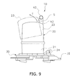
9 ist eine Dreiviertelansicht der Rundumkennleuchte 10 von vorne links, wobei der erste stangenförmige Abschnitt 41 nicht dargestellt ist. Wie 9 zeigt, ist ein Zwischenraum S zwischen der Rundumkennleuchte 10 und dem dritten stangenförmigen Abschnitt 43 gebildet. Das Abdeckelement 23 wird durch diesen Zwischenraum S hindurchbewegt (siehe den Pfeil T), wenn das Abdeckelement 23 beim Austausch der Glühbirne 22 entfernt wird. Insbesondere kann durch die Bildung des Zwischenraums S, durch welchen das Abdeckelement 23 zwischen dem dritten stangenförmigen Abschnitt 43 und der Rundumkennleuchte 10 hindurchtreten kann, entfernt werden, obwohl der Griff 40 derart vorgesehen ist, dass dieser die Rundumkennleuchte 20 umgibt, wie in dieser Ausführungsform, so dass die Glühbirne 22 mit Leichtigkeit ausgetauscht werden kann. In 9 ist das Abdeckelement 23, das abgenommen wird, anhand der Zweistrich-Punkt-Linie dargestellt. 9 is a three-quarter view of the rotating beacon 10 from the front left, with the first bar-shaped section 41 not shown. As 9 shows is a gap S between the rotating beacon 10 and the third bar-shaped portion 43 educated. The cover element 23 is moved through this gap S (see the arrow T) when the cover 23 when replacing the bulb 22 Will get removed. In particular, by the formation of the gap S, through which the cover 23 between the third bar-shaped section 43 and the rotating beacon 10 can pass, be removed, although the handle 40 is provided so that this is the rotating beacon 20 surrounds, as in this embodiment, so that the light bulb 22 can be exchanged with ease. In 9 is the cover element 23 , which is taken off, shown by the two-dot-dash line.
Funktionsweisefunctionality
2-1. Vorgang des Anbringens2-1. Process of attaching
10 zeigt schematisch den Zustand der Anbringung der Rundumkennleuchte 10 durch die Bedienungsperson auf dem Dach 5b der Kabine 5. 10 shows schematically the state of attachment of the rotating beacon 10 by the operator on the roof 5b the cabin 5 ,
Wie 10 zeigt, klettert die Bedienungsperson 70 auf eine Stufe oder eine andere Basis 80, hält sich zur Stabilisierung ihres Körpers mit der rechten Hand 71 in der Nähe des hinteren Endes der linken Seitenfläche 5c der Kabine 5 fest und hält die Rundumkennleuchte 10 in der linken Hand 72, um die Leuchte an dem Basiselement 50 zu befestigen. Das Basiselement 50 ist an dem Dach 5b befestigt, wie vorstehend erläutert wurde.As 10 shows, the operator climbs 70 on a level or another basis 80 , sticks to the stabilization of her body with the right hand 71 near the rear end of the left side surface 5c the cabin 5 firmly and holds the rotating beacon 10 in the left hand 72 to the light on the base element 50 to fix. The basic element 50 is on the roof 5b fastened, as explained above.
11 ist eine schematische Darstellung des Befestigungszustands der Rundumkennleuchte 10 an dem Basiselement 50 bei Betrachtung von der Rückseite. Wie 11 zeigt, hält die Bedienungsperson 70 den ersten stangenförmigen Abschnitt 41 der Rundumkennleuchte 10 und führt das zu begrenzende Element 33 in den Spalt 533 des Führungselements 53 ein, während die Seite der Rundumkennleuchte 10 mit dem zu begrenzenden Element 33 nach unten unter die Seite mit dem in Eingriff gebrachten Element 32 bewegt wird. 11 is a schematic representation of the mounting state of the rotating beacon 10 on the base element 50 when viewed from the back. As 11 shows, the operator stops 70 the first rod-shaped section 41 the rotating beacon 10 and leads the element to be limited 33 in the gap 533 of the guide element 53 while the side of the rotating beacon 10 with the element to be limited 33 down under the side with the engaged element 32 is moved.
12 ist ein Detailquerschnitt des Zustands des Einführens des zu begrenzenden Elements 33 in den Spalt 533 des Führungselements 53. Da die Durchgangsöffnung 531 in der Unterseite des Begrenzers 532 gebildet ist, wie in 12 gezeigt, kann das distale Ende des zu begrenzenden Elements 33 in die Durchgangsöffnung 531 eingeführt werden, so dass sich das zu begrenzende Element ohne weiteres diagonal von oben in den Spalt 533 einführen lässt. 12 Fig. 12 is a detail cross section of the state of insertion of the member to be limited 33 in the gap 533 of the guide element 53 , As the passage opening 531 in the bottom of the limiter 532 is formed, as in 12 can be shown, the distal end of the element to be limited 33 in the passage opening 531 be introduced so that the element to be bounded easily diagonally from above into the gap 533 can be introduced.
Da der erste stangenförmige Abschnitt 41 hier in der Richtung nach oben und nach unten vorgesehen ist, kann die Position der Rundumkennleuchte 10 in Richtung nach oben und nach unten (siehe den Pfeil Y in 11) bequem justiert werden. Wie Ferner in 8 gezeigt ist, liegt der erste stangenförmige Abschnitt 41 näher an der Mittelachse 20a des Rundumkennleuchten-Hauptkörpers 20a, was bedeutet, dass der erste stangenförmige Abschnitt 41 an einer Position näher am Schwerpunkt der Rundumkennleuchte 10 vorgesehen ist, und dies erleichtert die Justierung der Position der Rundumkennleuchte 10 in Pfeilrichtung Y.Because the first rod-shaped section 41 here in the direction up and down is provided, the position of the rotating beacon 10 in the upward and downward direction (see the arrow Y in 11 ) can be adjusted easily. Like further in 8th is shown, is the first rod-shaped portion 41 closer to the central axis 20a of the beacon main body 20a which means that the first rod-shaped section 41 at a position closer to the center of gravity of the rotating beacon 10 is provided, and this facilitates the adjustment of the position of the rotating beacon 10 in the direction of the arrow Y.
Danach, d.h. in einem Zustand, in dem sich das zu begrenzende Element 33 mit dem Ende 532e auf der linken Seite des Begrenzers 532 in Kontakt befindet (siehe 12), schwenkt die Bedienungsperson 70 die linke Seite der Rundumkennleuchte um das Ende 532e nach unten (Pfeil Q), um die Rundumkennleuchte 10 in die Position ihrer Anbringung an dem Basiselement 50 zu bringen. An diesem Punkt befinden sich die Kontaktebene 27a des zweiten Kontaktelements 37 und die Kontaktebene 36a des ersten Kontaktelements 36 des Befestigungselements 50 in Kontakt mit dem Basis-Hauptkörper 51 des Basiselements 50, und der erste Magnet 38 und der zweite Magnet 39 sind durch Magnetkraft an dem Basis-Hauptkörper 51 festgelegt (siehe 4). After that, ie in a state in which the element to be limited 33 with the end 532e on the left side of the limiter 532 is in contact (see 12 ), the operator pans 70 the left side of the rotating beacon around the end 532e down (arrow Q) to the rotating beacon 10 in the position of its attachment to the base member 50 bring to. At this point are the contact layer 27a of the second contact element 37 and the contact level 36a of the first contact element 36 of the fastener 50 in contact with the base main body 51 of the base element 50 , and the first magnet 38 and the second magnet 39 are by magnetic force on the base main body 51 set (see 4 ).
Bei Drehung der Rundumkennleuchte 10 in Pfeilrichtung Q, wie in 6 dargestellt, gelangt die Positionierlasche 34 in die erste Durchgangsnut 51a und die Positionierlasche 35 in die zweite Durchgangsnut 51b. Dies ermöglicht eine genauere Positionierung. Auch können die erste Positionierlasche 34 und die zweite Positionierlasche 35 leichter in die erste Durchgangsnut 51a und die zweite Durchgangsnut 51b eingeführt werden, da deren sich nach unten erstreckende Länge im Zuge der Bewegung in Richtung auf das Ende 532e, das als Drehpunkt dient, kürzer wird. When turning the rotating beacon 10 in the direction of arrow Q, as in 6 shown, the positioning tab arrives 34 in the first through groove 51a and the positioning tab 35 in the second passage groove 51b , This allows a more accurate positioning. Also, the first positioning tab 34 and the second positioning tab 35 easier in the first through-groove 51a and the second passage groove 51b be introduced as their downwardly extending length in the course of movement towards the end 532e , which serves as a fulcrum, becomes shorter.
Als nächstes wird der Haken 521 des Klammer-Hauptkörpers 52 an dem in Eingriff gebrachten Element 32 eingehakt und der Betätigungshebel 522 nach unten bewegt, um den Haken 521 mit dem in Eingriff gebrachten Element 32 in Eingriff zu bringen, und das Befestigungselement 30, an dem der Rundumkennleuchten-Hauptkörper 20 fixiert ist, wird selbst an dem Basiselement 50 festgelegt. Die vorstehend genannte Anbringungsposition kann auch als Position bezeichnet werden, in welcher der Haken an dem in Eingriff gebrachten Element 32 eingehakt und der Betätigungshebel 522 nach unten bewegt werden kann, d.h. als Position, in der ein Eingriff möglich ist. Next is the catch 521 of the bracket main body 52 on the engaged element 32 hooked and the operating lever 522 moved down to the hook 521 with the engaged element 32 engage, and the fastener 30 at which the beacon main body 20 is fixed itself to the base element 50 established. The above attachment position may also be referred to as a position in which the hook on the engaged element 32 hooked and the operating lever 522 can be moved down, ie as a position in which an intervention is possible.
13 zeigt in einer Schrägansicht den Zustand der an dem Basiselement 50 befestigten Rundumkennleuchte 10 bei Betrachtung von vorne rechts. Wie die 13 und 6 zeigen, ist das zu begrenzende Element 33 im Zustand der Befestigung der Rundumkennleuchte 10 an dem Basiselement 50 an der Unterseite des Begrenzers 532 angeordnet. 13 shows in an oblique view the state of the base element 50 fixed rotating beacon 10 when viewed from the front right. As the 13 and 6 show is the element to be limited 33 in the state of attachment of the rotating beacon 10 on the base element 50 at the bottom of the limiter 532 arranged.
Wie vorstehend erläutert wurde, wird ein Eingriffszustand erreicht durch das Einhängen des Hakens 521 an dem in Eingriff gebrachten Element 32 und durch das Bewegen des Betätigungshebels 522 nach unten. In diesem Eingriffszustand wird auf die Seite mit dem in Eingriff gebrachten Element 32 durch den Klammer-Hauptkörper 52 eine Kraft nach unten ausgeübt (siehe Pfeil D). Dementsprechend wird eine Kraft nach oben (siehe Pfeil U) auf das zu begrenzende Element 33 ausgeübt, das sich auf der gegenüberliegenden Seite des in Eingriff gebrachten Elements 32 befindet und den Rundumkennleuchten-Hauptkörper 20 flankiert. Da sich aber der Begrenzer 532 an der Oberseite des zu begrenzenden Elements 33 befindet, trifft das zu begrenzende Element 33 auf den Begrenzer 532, wodurch die Bewegung begrenzt wird. Dadurch wird die Rundumkennleuchte 10 an dem Basiselement 10 festgelegt.As explained above, an engaged state is achieved by suspending the hook 521 on the engaged element 32 and by moving the operating lever 522 downward. In this engaged state is on the side with the engaged element 32 through the bracket main body 52 a force applied downward (see arrow D). Accordingly, an upward force (see arrow U) on the element to be limited 33 exerted on the opposite side of the engaged element 32 located and the beacon main body 20 flanked. But since the limiter 532 at the top of the element to be limited 33 is, hits the limiting element 33 on the limiter 532 , which limits the movement. This turns the rotating beacon 10 on the base element 10 established.
Da der erste Magnet 38 und der zweite Magnet 39 an der Unterseite des Befestigungselements 30 vorgesehen sind, erfolgt die Festlegung des Befestigungselements 30 an dem Basis-Hauptkörper 51 durch die Magnetkraft des ersten Magnets 38 und des zweiten Magnets 39. Auf diese Weise wird verhindert, dass die Rundumkennleuchte 10 versehentlich herunterfällt, auch wenn die Bedienungsperson vorrübergehend die linke Hand 72 von dem Griff 40 nimmt, um das Befestigungselement 30 mit der linken Hand 72 mittels des Klammer-Hauptkörpers 52 an dem Basiselement 50 zu befestigen. Because the first magnet 38 and the second magnet 39 at the bottom of the fastener 30 are provided, the determination of the fastening element takes place 30 on the base main body 51 by the magnetic force of the first magnet 38 and the second magnet 39 , In this way it is prevented that the rotating beacon 10 accidentally falls off, even if the operator temporarily left hand 72 from the handle 40 takes to the fastener 30 with the left hand 72 by means of the staple main body 52 on the base element 50 to fix.
2-2. Vorgang des Abnehmens2-2. Process of losing weight
Wenn die Rundumkennleuchte 10 beim Transport des Hydraulikbaggers 100 entfernt werden muss, wird der Betätigungshebel 522 des Klammer-Hauptkörpers 52 nach oben bewegt und der Haken 521 aus dem in Eingriff gebrachten Element 32 gelöst. Danach wird der erste stangenförmige Abschnitt 41 umgriffen und die Seite mit dem in Eingriff gebrachten Element 32 nach oben bewegt, um das begrenzte Element 33 von dem Führungselement 53 zu entriegeln, wodurch die Rundumkennleuchte 10 von dem Basiselement 50 entfernt werden kann. If the rotating beacon 10 during transport of the hydraulic excavator 100 must be removed, the operating lever 522 of the bracket main body 52 moved up and the hook 521 from the engaged element 32 solved. After that, the first rod-shaped section 41 embraced and the side with the engaged element 32 moved up to the limited element 33 from the guide element 53 to unlock, causing the rotating beacon 10 from the base element 50 can be removed.
Sogar nach dem Lösen der Fixierung durch den Klammer-Hauptkörper 52 bleibt das Befestigungselement 30 dank der Magnetkraft des ersten Magnets 38 und des zweiten Magnets 39 noch an dem Basis-Hauptkörper 51 fixiert, wodurch verhindert wird, dass die Rundumkennleuchte 10 versehentlich herunterfällt. Even after releasing the fixation by the staple main body 52 remains the fastener 30 thanks to the magnetic force of the first magnet 38 and the second magnet 39 still on the base main body 51 fixed, which prevents the rotating beacon 10 accidentally falls off.
3. Merkmale etc. 3. Features etc.
3-13-1
Der Hydraulikbagger 100 (ein Beispiel eines Arbeitsfahrzeugs) dieser Ausführungsform ist ein Arbeitsfahrzeug, das mit dem Arbeitsgerät 4 versehen ist und eine Kabine 5 und eine Rundumkennleuchte 10 hat. Die Kabine 5 hat in ihrem oberen Bereich das Dach 5b, und links und rechts sind die linke Seitenfläche 5c (Beispiel einer zweiten Seitenfläche) und die rechte Seitenfläche 5a (Beispiel einer ersten Seitenfläche) vorgesehen. Die Rundumkennleuchte 10 ist abnehmbar auf dem Dach 5b der Kabine 5 angeordnet. Die Rundumkennleuchte 10 hat den Rundumkennleuchten-Hauptkörper 20, das Befestigungselement 30 und den Griff 40. Das Befestigungselement 30 ist an der Unterseite des Rundumkennleuchten-Hauptkörpers 20 befestigt, und der Rundumkennleuchten-Hauptkörper 20 ist an dem Dach 5b befestigt. Der Griff 40 ist portalförmig und an dem Befestigungselement 30 festgelegt und hat den ersten stangenförmigen Abschnitt 41, den zweiten stangenförmigen Abschnitt 42 und den dritten stangenförmigen Abschnitt 43. Der erste stangenförmige Abschnitt 41 und der zweite stangenförmige Abschnitt 42 sind von dem Befestigungselement 30 nach oben weisend ausgebildet. Der dritte stangenförmige Abschnitt 43 verbindet den ersten stangenförmigen Abschnitt 41 und den zweiten stangenförmigen Abschnitt 42. Der erste stangenförmige Abschnitt 41 ist vor dem zweiten stangenförmigen Abschnitt 42 angeordnet. Der zweite stangenförmige Abschnitt 42 ist mehr zur Rückseite angeordnet als der Rundumkennleuchten-Hauptkörper 20 und ist mehr auf der Seite der rechten Seitenfläche 5a angeordnet als der erste stangenförmige Abschnitt. Wie 7b zeigt, ist der dritte stangenförmige Abschnitt 43 bei Betrachtung von der Seite und senkrecht zur Längsrichtung (Pfeilrichtung E) (bei Betrachtung in Pfeilrichtung G) auf der Oberseite des Rundumkennleuchten-Hauptkörpers 20 angeordnet. The hydraulic excavator 100 (an example of a work vehicle) of this embodiment is a work vehicle that is connected to the work implement 4 is provided and a cabin 5 and a rotating beacon 10 Has. The cabin 5 has the roof in its upper area 5b , and left and right are the left side surface 5c (Example of a second side surface) and the right side surface 5a (Example of a first side surface) provided. The rotating beacon 10 is removable on the roof 5b the cabin 5 arranged. The rotating beacon 10 has the beacon main body 20 , the fastener 30 and the handle 40 , The fastener 30 is at the bottom of the beacon main body 20 attached, and the beacon main body 20 is on the roof 5b attached. The handle 40 is portal-shaped and on the fastener 30 set and has the first rod-shaped section 41 , the second rod-shaped section 42 and the third bar-shaped section 43 , The first bar-shaped section 41 and the second rod-shaped portion 42 are from the fastener 30 formed facing up. The third bar-shaped section 43 connects the first bar-shaped section 41 and the second rod-shaped portion 42 , The first bar-shaped section 41 is in front of the second bar-shaped section 42 arranged. The second bar-shaped section 42 is located more to the rear than the rotating beacon main body 20 and is more on the side of the right side surface 5a arranged as the first rod-shaped section. As 7b shows is the third bar-shaped section 43 when viewed from the side and perpendicular to the longitudinal direction (arrow direction E) (when viewed in the direction of arrow G) on the top of the Rundumkennleuchten main body 20 arranged.
Wenn die Rundumkennleuchte 10 auf dem Dach 5b der Kabine 5 angebracht wird, wie in 10 dargestellt, hält sich die Bedienungsperson 70 wegen des hoch liegenden Daches 5b mit der rechten Hand 71 an der Kabine 5 fest und benutzt die andere (linke) Hand 72 zum Anbringen der Rundumkennleuchte 10. Dabei kann die Bedienungsperson 70 auf die Rundumkennleuchte 10 in Richtung nach oben und nach unten eine Kraft ausüben (siehe den Pfeil Y in 11), indem die Bedienungsperson den ersten stangenförmigen Abschnitt 41, der nach oben weisend ausgebildet ist, umgreift. Auf diese Weise lässt sich verhindern, dass die Rundumkennleuchte 10 in Richtung nach oben und nach unten wackelt (siehe den Pfeil Y in 11), auch wenn die Rundumkennleuchte 10 mit nur einer Hand an dem Dach 5b der Kabine 5 befestigt wird. Die Rundumkennleuchte 10 lässt sich daher einfacher anbringen und abnehmen.If the rotating beacon 10 on the roof 5b the cabin 5 is attached as in 10 represented, the operator holds 70 because of the high-lying roof 5b with the right hand 71 at the cabin 5 firmly and use the other (left) hand 72 for attaching the rotating beacon 10 , In this case, the operator 70 on the rotating beacon 10 exert a force in the direction of upwards and downwards (see the arrow Y in 11 ) by the operator the first rod-shaped section 41 which is formed facing upwards, embraces. In this way you can prevent the rotating beacon 10 wiggles up and down (see the arrow Y in 11 ), even if the rotating beacon 10 with only one hand on the roof 5b the cabin 5 is attached. The rotating beacon 10 can therefore be easier to attach and remove.
Da der dritte stangenförmige Abschnitt 43 des Griffes 40 weiter oben als der Rundumkennleuchten-Hauptkörper 20 angeordnet ist, blockiert der dritte stangenförmige Abschnitt 43 weniger von dem Licht, das von dem Rundumkennleuchten-Hauptkörper 20 abgestrahlt wird. Because the third rod-shaped section 43 of the handle 40 above as the beacon main body 20 is arranged, blocks the third rod-shaped portion 43 less of the light coming from the beacon main body 20 is emitted.
Da der Griff 40 außerdem portalförmig ist, lässt sich beim Abnehmen der Rundumkennleuchte 10 von der Kabine 5 der dritte stangenförmige Abschnitt 43 umgreifen und die Rundumkennleuchte 10 leichter tragen. Because the handle 40 is also portal-shaped, can be when removing the rotating beacon 10 from the cabin 5 the third bar-shaped section 43 embrace and the rotating beacon 10 easier to carry.
Da der Griff 40 portalförmig ist, verfügt er über eine angemessene Stabilität.Because the handle 40 is portal-shaped, it has adequate stability.
Da der zweite stangenförmige Abschnitt 42 mehr zur Rückseite angeordnet ist als der Rundumkennleuchten-Hauptkörper 20, lässt sich verhindern, dass Objekte von der Rückseite mit dem Rundumkennleuchten-Hauptkörper 20 kollidieren. Because the second rod-shaped section 42 is arranged more to the rear than the Rundumkennleuchten main body 20 , Prevents objects from the back with the beacon main body 20 collide.
3-23-2
Wie in 7 gezeigt ist, ist bei dem Hydraulikbagger 100 in dieser Ausführungsform ein Teil des dritten stangenförmigen Abschnitts 43 bei Draufsicht dem Rundumkennleuchten-Hauptkörper 20 überlagert. As in 7 is shown in the hydraulic excavator 100 in this embodiment, a part of the third bar-shaped portion 43 in top view the Rundumkennleuchten main body 20 superimposed.
Die Ausbildung des Griffes 40 derart, dass der Griff den Rundumkennleuchten-Hauptkörper 20 überspannt, erlaubt eine Anordnung des ersten stangenförmigen Abschnitts 41 und des zweiten stangenförmigen Abschnitts 42 näher am Schwerpunkt des Rundumkennleuchten-Hauptkörpers 10. Dadurch ist es einfacher für die Bedienungsperson zu verhindern, dass die Rundumkennleuchte 10 in Richtung nach oben und nach unten wackelt (siehe den Pfeil Y in 11).The training of the handle 40 such that the handle is the flashing beacon main body 20 spans, allows an arrangement of the first rod-shaped portion 41 and the second rod-shaped portion 42 closer to the center of gravity of the beacon main body 10 , This makes it easier for the operator to prevent the rotating beacon 10 wiggles up and down (see the arrow Y in 11 ).
3-33-3
Bei dem Hydraulikbagger 100 in dieser Ausführungsform hat der Rundumkennleuchten-Hauptkörper 20 das Basiselement 21, die Glühbirne 22 (ein Beispiel einer Lichtquelle) und das Abdeckelement 23. Das Basiselement 21 ist an dem Befestigungselement 30 befestigt. Die Glühbirne 22 ist an der Innenseite des Basiselements 21 befestigt. Das Abdeckelement 23 deckt die Glühbirne 22 von oben ab und ist an dem Basiselement 21 abnehmbar befestigt. Wie 9 zeigt, ist zwischen dem dritten stangenförmigen Abschnitt 43 und dem Abdeckelement 23 ein bestimmter Zwischenraum S vorhanden, durch welchen das Abdeckelement 23 hindurchtreten kann, wenn das Abdeckelement 23 von dem Basiselement 21 entfernt wird.In the hydraulic excavator 100 In this embodiment, the rotating beacon main body has 20 the basic element 21 , the light bulb 22 (an example of a light source) and the cover member 23 , The basic element 21 is on the fastener 30 attached. The light bulb 22 is on the inside of the base element 21 attached. The cover element 23 covers the bulb 22 from above and is on the base element 21 detachably attached. As 9 is between the third bar-shaped section 43 and the cover member 23 a certain gap S exists, through which the cover 23 can pass through when the cover element 23 from the base element 21 Will get removed.
Da der bestimmte Zwischenraum S zwischen dem dritten stangenförmigen Abschnitt 43 und dem Abdeckelement 23 gebildet ist, kann das Abdeckelement 23 immer noch ohne weiteres an dem Basiselement 21 angebracht und von dem Basiselement 21 abgenommen werden, auch wenn um den Rundumkennleuchten-Hauptkörper 20 der Griff 40 vorgesehen ist. Die Glühbirne 22 kann dadurch leichter ausgewechselt werden. Since the certain gap S between the third bar-shaped portion 43 and the cover member 23 is formed, the cover can 23 still readily on the base element 21 attached and from the base element 21 even when around the flashing lights main body 20 the handle 40 is provided. The light bulb 22 This makes it easier to replace.
3-43-4
Bei dem Hydraulikbagger 100 in dieser Ausführungsform ist das Arbeitsgerät 4 zur Seite der rechten Seitenfläche 5a der Kabine 5 angeordnet. Die Rundumkennleuchte 10 ist an dem Ende auf der Seite der rechten Seitenfläche 5c des Daches 5b angeordnet. Der erste stangenförmige Abschnitt 41 ist dem Rundumkennleuchten-Hauptkörper 20 bei Betrachtung von der Seite der linken Seitenfläche 5c (von der linken Seite) überlagert.In the hydraulic excavator 100 in this embodiment, the implement is 4 to the side of the right side surface 5a the cabin 5 arranged. The rotating beacon 10 is at the end on the side of the right side surface 5c of the roof 5b arranged. The first bar-shaped section 41 is the rotary beacon main body 20 when viewed from the side of the left side surface 5c (from the left side) superimposed.
Da die Rundumkennleuchte 10 dadurch auf der dem Arbeitsgerät 4 gegenüberliegenden Seite auf der Oberseite der linken Seitenfläche 5c der Kabine 5 angeordnet ist, kann die Bedienungsperson 70 die Rundumkennleuchte 10 von außerhalb des Hydraulikbaggers 100 anbringen, ohne hierfür in den Hydraulikbagger 100 klettern zu müssen. Because the rotating beacon 10 by doing so on the implement 4 opposite side on top of the left side surface 5c the cabin 5 is arranged, the operator can 70 the rotating beacon 10 from outside the hydraulic excavator 100 attach without this in the hydraulic excavator 100 to have to climb.
Da ein Teil des ersten stangenförmigen Abschnitts 41 dem Rundumkennleuchten-Hauptkörper 20 überlagert ist, kann der erste stangenförmige Abschnitt 41 näher an dem Rundumkennleuchten-Hauptkörper 20 angeordnet sein. Das heißt, da der erste stangenförmige Abschnitt 41 näher am Schwerpunkt der Rundumkennleuchte 10 angeordnet sein kann, ist es einfacher für die Bedienungsperson 70 zu verhindern, dass die Rundumkennleuchte 10 in Richtung nach oben und nach unten wackelt (die Richtung Y). As part of the first rod-shaped section 41 the rotary beacon main body 20 is superimposed, the first rod-shaped section 41 closer to the rotating beacon main body 20 be arranged. That is, because the first rod-shaped section 41 closer to the center of gravity of the rotating beacon 10 can be arranged, it is easier for the operator 70 to prevent the rotating beacon 10 wiggles up and down (the direction Y).
Da der erste stangenförmige Bereich 41 mehr zur Seite der linken Seitenfläche 5c angeordnet ist als der Rundumkennleuchten-Hauptkörper 20, lässt sich verhindern, dass Objekte von der Seite der linken Seitenfläche 5c mit dem Rundumkennleuchten-Hauptkörper 20 kollidieren.Because the first rod-shaped area 41 more to the side of the left side surface 5c is arranged as the Rundumkennleuchten main body 20 , lets prevent objects from the side of the left side surface 5c with the beacon main body 20 collide.
3-53-5
Der Hydraulikbagger 100 in dieser Ausführungsform umfasst ferner das Basiselement 50, das an dem Dach 5b befestigt ist und an dem das Befestigungselement 30 abnehmbar festgelegt ist. Das Basiselement 50 hat den Klammer-Hauptkörper 52 (ein Beispiel eines Eingriffselements) und das Führungselement 53. Der Klammer-Hauptkörper 52 kann mit dem Befestigungselement 30 in Eingriff gebracht werden. Das Führungselement 53 führt das Befestigungselement 30 in eine Position, in der es mit dem Klammer-Hauptkörper 52 in Eingriff gebracht werden kann, und hat einen Begrenzer 532. Der Begrenzer 532 begrenzt die Bewegung des Befestigungselements 30 in einem Zustand, in dem dieses sich, nachdem es in die Position geführt wurde, mit dem Klammer-Hauptköper 52 im Eingriff befindet. Das Befestigungselement 30 hat das in Eingriff gebrachte Element 32 und das zu begrenzende Element 33. Das in Eingriff gebrachte Element 32 wird mit dem Klammer-Hauptkörper 52 in Eingriff gebracht. Das zu begrenzende Element 33 ist auf der gegenüberliegenden Seite des in Eingriff gebrachten Elements 32 angeordnet und überspannt den Rundumkennleuchten-Hauptkörper 20. In einem Zustand, in dem der Klammer-Hauptkörper 52 mit dem in Eingriff gebrachten Element 32 in Eingriff gebracht wurde, wie in 13 gezeigt, ist das in Eingriff gebrachte Element 32 nach unten vorgespannt (Pfeilrichtung D), was bewirkt, dass das zu begrenzende Element 33 nach oben vorgespannt wird (Pfeilrichtung U) und auf den Begrenzer 532 trifft und dass das Befestigungselement 30 an dem Basiselement 50 festgelegt wird. The hydraulic excavator 100 in this embodiment further comprises the base member 50 that on the roof 5b is attached and to which the fastener 30 is detachably fixed. The basic element 50 has the clip main body 52 (an example of an engaging member) and the guide member 53 , The staple main body 52 can with the fastener 30 be engaged. The guide element 53 leads the fastener 30 in a position where it is with the staple main body 52 can be engaged, and has a limiter 532 , The limiter 532 limits the movement of the fastener 30 in a state in which this, after being led into the position, with the staple main twill 52 engaged. The fastener 30 has the engaged element 32 and the element to be limited 33 , The engaged element 32 becomes with the staple main body 52 engaged. The element to be limited 33 is on the opposite side of the engaged element 32 arranged and spans the Rundumkennleuchten main body 20 , In a state where the staple main body 52 with the engaged element 32 was engaged, as in 13 shown is the engaged element 32 biased downwards (arrow D), which causes the element to be limited 33 is biased upward (arrow U) and on the limiter 532 meets and that the fastener 30 on the base element 50 is determined.
Die Festlegung des Befestigungselements 30 an dem Basiselement 50 ist also möglich, indem das Befestigungselement 30 lediglich entlang des Führungselements 53 an dem Basiselement 50 in Anordnung gebracht wird und das Basiselement 50 und das Befestigungselement 30 in Eingriff gebracht werden. Die Rundumkennleuchte 10 lässt sich daher einfach auf dem Dach 5b anbringen und ebenso einfach von dem Dach 5b abnehmen, indem der Eingriff lediglich gelöst wird. The determination of the fastener 30 on the base element 50 is therefore possible by the fastener 30 only along the guide element 53 on the base element 50 is placed in order and the base element 50 and the fastener 30 be engaged. The rotating beacon 10 can therefore be easily on the roof 5b attach and just as easily from the roof 5b decrease by the engagement is only solved.
3-63-6
Bei dem Hydraulikbagger 100 in dieser Ausführungsform ist das Arbeitsgerät 4 zur Seite der rechten Seitenfläche 5a der Kabine 5 angeordnet. Die Rundumkennleuchte 10 ist an dem Ende des Daches 5b auf der Seite der linken Seitenfläche 5c angeordnet. Der Klammer-Hauptkörper 52 (ein Beispiel eines Eingriffselements) und das in Eingriff gebrachte Element 32 sind auf der Seite der linken Seitenfläche 5c des Rundumkennleuchten-Hauptkörpers 20 angeordnet.In the hydraulic excavator 100 in this embodiment, the implement is 4 to the side of the right side surface 5a the cabin 5 arranged. The rotating beacon 10 is at the end of the roof 5b on the side of the left side surface 5c arranged. The staple main body 52 (an example of an engagement member) and the engaged member 32 are on the side of the left side surface 5c of the beacon main body 20 arranged.
Da der Klammer-Hauptkörper 52 auf der Oberseite der dem Arbeitsgerät 4 gegenüberliegenden linken Seitenfläche 5c der Kabine 5 angeordnet ist, wie in 10 gezeigt, kann die Bedienungsperson 70 den Klammer-Hauptkörper 52 von außerhalb des Hydraulikbaggers 100 in und außer Eingriff bringen, ohne hierfür in den Hydraulikbagger 100 klettern zu müssen. Die Rundumkennleuchte 10 lässt sich dadurch einfacher abnehmen und anbringen.As the staple main body 52 on the top of the implement 4 opposite left side surface 5c the cabin 5 is arranged as in 10 shown, the operator can 70 the clip main body 52 from outside the hydraulic excavator 100 in and disengage, without this in the hydraulic excavator 100 to have to climb. The rotating beacon 10 makes it easier to remove and attach.
3-7 3-7
Bei dem Hydraulikbagger 100 in dieser Ausführungsform hat das Befestigungselement 30 ferner einen ersten Magnet 38 und einen zweiten Magnet 39 (ein Beispiel von Befestigungselementen), die das Basiselement 50 an der Unterseite des Befestigungselements 30 magnetisch festlegen. In the hydraulic excavator 100 in this embodiment, the fastener has 30 also a first magnet 38 and a second magnet 39 (an example of fasteners), which is the base element 50 at the bottom of the fastener 30 set magnetically.
Da hier ferner der erste Magnet 38 und der zweite Magnet 390 vorgesehen sind, die das Befestigungselement 30 an dem Basiselement 50 festlegen, ist es weniger wahrscheinlich, dass die Rundumkennleuchte 10 versehentlich vom Dach fällt, wenn der Klammer-Hauptkörper 52 von dem in Eingriff gebrachten Element 32 gelöst wird.Since here also the first magnet 38 and the second magnet 390 are provided, which are the fastener 30 on the base element 50 set, it is less likely that the rotating beacon 10 accidentally falls off the roof when the bracket main body 52 from the engaged element 32 is solved.
3-83-8
Die Rundumkennleuchte 10 des Hydraulikbaggers 100 in dieser Ausführungsform ist abnehmbar auf dem Dach 5b angeordnet, das im oberen Bereich der Kabine 5 vorgesehen ist, und hat den Rundumkennleuchten-Hauptkörper 20, das Befestigungselement 30 und den Griff 40. Das Befestigungselement 30 ist an der Unterseite des Rundumkennleuchten-Hauptkörpers 20 vorgesehen und dient der Anbringung des Rundumkennleuchten-Hauptkörpers 20 auf dem Dach 5b. Der Griff 40 ist portalförmig und ist an dem Befestigungselement 30 befestigt. Der Griff 40 hat den ersten stangenförmigen Abschnitt 41, den zweiten stangenförmigen Abschnitt 42 und den dritten stangenförmigen Abschnitt 43. Der erste stangenförmige Abschnitt 41 und der zweite stangenförmige Abschnitt 42 sind von dem Befestigungselement 30 nach oben weisend ausgebildet. Der dritte stangenförmige Abschnitt 43 verbindet den ersten stangenförmigen Abschnitt 41 und den zweiten stangenförmigen Abschnitt 42 miteinander. Ein Teil des dritten stangenförmigen Abschnitts 43 ist in Draufsicht dem Rundumkennleuchten-Hauptkörper 20 überlagert. The rotating beacon 10 of the hydraulic excavator 100 in this embodiment is removable on the roof 5b arranged in the upper part of the cabin 5 is provided, and has the Rundumkennleuchten main body 20 , the fastener 30 and the handle 40 , The fastener 30 is at the bottom of the beacon main body 20 provided and serves to attach the Rundumkennleuchten main body 20 on the roof 5b , The handle 40 is portal-shaped and is on the fastener 30 attached. The handle 40 has the first bar-shaped section 41 , the second rod-shaped section 42 and the third bar-shaped section 43 , The first bar-shaped section 41 and the second rod-shaped portion 42 are from the fastener 30 formed facing up. The third bar-shaped section 43 connects the first bar-shaped section 41 and the second rod-shaped portion 42 together. Part of the third bar-shaped section 43 is in plan view the Rundumkennleuchten main body 20 superimposed.
Durch die Ausbildung des Griffes 40 derart, dass dieser den Rundumkennleuchten-Hauptkörper 20 überspannt, können der erste stangenförmige Abschnitt 41 und der zweite stangenförmige Abschnitt 42 näher an dem Schwerpunkt der Rundumkennleuchte 10 angeordnet sein, weshalb es einfacher ist für die Bedienungsperson zu verhindern, dass die Rundumkennleuchte 10 in Richtung nach oben und nach unten wackelt. Das Anbringen und Abnehmen der Rundumkennleuchte 10 an und von dem Dach 5b wird auf diese Weise erleichtert. By training the handle 40 such that this is the rotary beacon main body 20 spanned, the first rod-shaped section 41 and the second rod-shaped portion 42 closer to the center of gravity of the rotating beacon 10 be arranged, which is why it is easier for the operator to prevent the rotating beacon 10 wiggles up and down. Attaching and removing the rotating beacon 10 on and off the roof 5b is facilitated in this way.
4. Weitere Ausführungsformen 4. Other embodiments
Eine Ausführungsform der vorliegenden Erfindung wurde vorstehend beschrieben. Die Erfindung ist jedoch nicht auf diese Ausführungsform beschränkt, sondern erlaubt innerhalb ihres Rahmens verschiedene Modifikationen. An embodiment of the present invention has been described above. However, the invention is not limited to this embodiment, but allows various modifications within its scope.
(A)(A)
In der vorstehenden Ausführungsform ist ein Teil des dritten stangenförmigen Abschnitts 43 bei Betrachtung von oben dem Rundumkennleuchten-Hauptkörper 20 überlagert. Jedoch muss es nicht sein, dass ein Teil des dritten stangenförmigen Abschnitts 43 bei Betrachtung von oben dem Rundumkennleuchten-Hauptkörper 20 überlagert ist. In the above embodiment, a part of the third bar-shaped portion 43 when viewed from above, the rotating beacon main body 20 superimposed. However, it does not have to be that part of the third rod-shaped section 43 when viewed from above, the rotating beacon main body 20 is superimposed.
Wie bei dem Griff 40', der in 14a dargestellt ist, kann die Konfiguration zum Beispiel dergestalt sein, dass der zweite stangenförmige Abschnitt 42 mehr nach links angeordnet ist als in der vorstehenden Ausführungsform, so dass der dritten stangenförmige Abschnitt 43 dem Rundumkennleuchten-Hauptkörper 20 bei Betrachtung von oben nicht überlagert ist. Hier ist der dritte stangenförmige Abschnitt 43 bei Betrachtung entlang der Pfeilrichtung G', welche eine Seite (der Pfeil G' oder H') senkrecht zur Längsrichtung (der Pfeil E') ist, auf der Oberseite des Rundumkennleuchten-Hauptkörpers 20 angeordnet, wie in 14b dargestellt ist. As with the handle 40 ' who in 14a For example, the configuration may be such that the second rod-shaped portion 42 is arranged more to the left than in the preceding embodiment, so that the third rod-shaped portion 43 the rotary beacon main body 20 when viewed from above is not superimposed. Here is the third bar-shaped section 43 when viewed along the arrow direction G ', which is one side (the arrow G' or H ') perpendicular to the longitudinal direction (the arrow E') on the top of the rotating beacon main body 20 arranged as in 14b is shown.
Es ist daher nicht notwendig, dass ein Teil des dritten stangenförmigen Abschnitts 43 dem Rundumkennleuchten-Hauptkörper 20 überlagert ist, wobei wesentlich ist, dass der dritte stangenförmige Abschnitt 43 bei Betrachtung von der Seite und senkrecht zur Längsrichtung (d.h. in Seitenansicht) auf der Oberseite des Rundumkennleuchten-Hauptkörpers 20 angeordnet ist. It is therefore not necessary that part of the third rod-shaped section 43 the rotary beacon main body 20 superimposed, wherein it is essential that the third rod-shaped section 43 as seen from the side and perpendicular to the longitudinal direction (ie, in side view) on the top of the Rundumkennleuchten main body 20 is arranged.
(B)(B)
In der vorstehenden Ausführungsform sind der erste stangenförmige Abschnitt 41 und der zweite stangenförmige Abschnitt 42 gleich hoch, und der dritte stangenförmige Abschnitt 43 ist horizontal gebildet, doch kann die Höhe des ersten stangenförmigen Abschnitts 41 und des zweiten stangenförmigen Abschnitts 42 auch ungleich sein, und der dritte stangenförmige Abschnitt 43 muss nicht horizontal sein. In the above embodiment, the first rod-shaped portion 41 and the second rod-shaped portion 42 the same height, and the third bar-shaped section 43 is formed horizontally, but the height of the first rod-shaped section 41 and the second rod-shaped portion 42 also be uneven, and the third bar-shaped section 43 does not have to be horizontal.
(C)(C)
In der vorstehenden Ausführungsform sind der erste stangenförmige Abschnitt 41 und der zweite stangenförmige Abschnitt 42 vertikal, können jedoch auch geneigt sein. Wesentlich ist, dass diese nach oben weisen.In the above embodiment, the first rod-shaped portion 41 and the second rod-shaped portion 42 vertical, but may also be inclined. It is essential that they point upwards.
(D)(D)
In der vorstehenden Ausführungsform verbindet der dritte stangenförmige Abschnitt 43 das obere Ende 41a des ersten stangenförmigen Abschnitts und das obere Ende 42a des zweiten stangenförmigen Abschnitts 42. Jedoch muss der dritte stangenförmige Abschnitt 43 die oberen Enden 41a und 42a nicht notwendigerweise verbinden. Das obere Ende 41 des ersten stangenförmigen Abschnitts 41 und/oder das obere Ende 42a des zweiten stangenförmigen Abschnitts 42 können von dem dritten stangenförmigen Abschnitt 43 nach oben vorspringen. Diese Konfiguration ist ebenfalls von der in vorliegender Beschreibung genannten "Portalform" umfasst.In the above embodiment, the third bar-shaped portion connects 43 the upper end 41a of the first rod-shaped portion and the upper end 42a of the second rod-shaped portion 42 , However, the third rod-shaped section needs 43 the upper ends 41a and 42a not necessarily connect. The upper end 41 of the first rod-shaped section 41 and / or the top 42a of the second rod-shaped portion 42 can from the third rod-shaped section 43 to project upwards. This configuration is also encompassed by the "portal shape" referred to in the present specification.
INDUSTRIELLE ANWENDBARKEITINDUSTRIAL APPLICABILITY
Bei dem Arbeitsfahrzeug und der Rundumkennleuchte gemäß vorliegender Erfindung wird das Anbringen und Abnehmen der Rundumkennleuchte erleichtert, wobei die Rundumkennleuchte bei vielen verschiedenen Arbeitsfahrzeugen Verwendung findet, wie zum Beispiel bei einem Hydraulikbagger.In the work vehicle and the rotating beacon according to the present invention, the attachment and detachment of the rotating beacon is facilitated, the beacon is used in many different work vehicles, such as a hydraulic excavator.
BezugszeichenlisteLIST OF REFERENCE NUMBERS
-
11
-
Arbeitsfahrzeug working vehicle
-
22
-
Fahreinheit driving unit
-
2a2a
-
Fahreinrichtung drive system
-
2b2 B
-
Fahreinrichtung drive system
-
2d2d
-
Raupenkette caterpillar track
-
2e2e
-
Raupenkette caterpillar track
-
33
-
Dreheinheit rotary unit
-
44
-
Arbeitsgerät implement
-
55
-
Kabine cabin
-
5a5a
-
rechte Seitenfläche (Beispiel einer ersten Seitenfläche) right side surface (example of a first side surface)
-
5b5b
-
Dach top, roof
-
5c5c
-
linke Seitenfläche (Beispiel einer zweiten Seitenfläche) left side surface (example of a second side surface)
-
66
-
Gegengewicht counterweight
-
77
-
Ausleger boom
-
88th
-
Stiel stalk
-
99
-
Grablöffel grave spoon
-
1010
-
Rundumkennleuchte Rotating beacon
-
2020
-
Rundumkennleuchten-Hauptkörper Rundumkennleuchten main body
-
20a20a
-
Mittelachse central axis
-
2121
-
Basiselement base element
-
2222
-
Glühbirne (Beispiel einer Lichtquelle) Light bulb (example of a light source)
-
2323
-
Abdeckelement cover
-
2424
-
Verbinder Interconnects
-
27a27a
-
Kontaktebene Contact level
-
3030
-
Befestigungselement fastener
-
3131
-
Stützelement support element
-
31a31a
-
erster flacher Bereich first flat area
-
31b31b
-
zweiter flacher Bereich second flat area
-
31c31c
-
dritter flacher Bereich third flat area
-
3232
-
in Eingriff gebrachtes Element engaged element
-
3333
-
begrenztes Element limited element
-
3434
-
erste Positionierlasche first positioning tab
-
3535
-
zweite Positionierlasche second positioning tab
-
3636
-
erstes Kontaktelement first contact element
-
36a36a
-
Kontaktebene Contact level
-
3737
-
zweites Kontaktelement second contact element
-
37a37a
-
Kontaktebene Contact level
-
3838
-
erster Magnet (Beispiel eines Festlegungselements) first magnet (example of a fixing element)
-
3939
-
zweiter Magnet (Beispiel eines Festlegungselements) second magnet (example of a fixing element)
-
4040
-
Griff Handle
-
40'40 '
-
Griff Handle
-
4141
-
erster stangenförmiger Abschnitt first rod-shaped section
-
41a41a
-
oberes Ende top end
-
41b41b
-
unteres Ende lower end
-
4242
-
zweiter stangenförmiger Abschnitt second rod-shaped section
-
42a42a
-
oberes Ende top end
-
42b42b
-
unteres Ende lower end
-
4343
-
dritter stangenförmiger Abschnitt third bar-shaped section
-
5050
-
Basiselement base element
-
5151
-
Basis-Hauptkörper Basic main body
-
51a51a
-
erste Durchgangsnut first passage groove
-
51b51b
-
zweite Durchgangsnut second passage groove
-
51h51h
-
Durchgangsöffnung Through opening
-
5252
-
Klammer-Hauptkörper (Beispiel eines Eingriffselements) Staple main body (example of an engaging element)
-
5353
-
Führungselement guide element
-
6060
-
Bolzen bolt
-
7070
-
Bedienungsperson operator
-
7171
-
rechte Hand right hand
-
7272
-
linke Hand left hand
-
8080
-
Basis Base
-
100100
-
Hydraulikbagger (Beispiel eines Arbeitsfahrzeugs) Hydraulic excavator (example of a work vehicle)
-
311311
-
Randbereich border area
-
311a311
-
Sitz Seat
-
311b311b
-
Sitz Seat
-
511511
-
Randbereich border area
-
511a511a
-
zentraler Bereich central area
-
521521
-
Haken hook
-
522522
-
Betätigungshebel actuating lever
-
531531
-
Durchgangsöffnung Through opening
-
532532
-
Begrenzer limiter
-
532a532a
-
vorderer Endbereich front end area
-
532b532b
-
hinterer Endbereich rear end area
-
532c532c
-
zentraler Bereich central area
-
532e532e
-
Ende The End
-
533533
-
Spalt gap
-
SS
-
Zwischenraum gap