DE10316632B4 - measuring device - Google Patents
measuring device Download PDFInfo
- Publication number
- DE10316632B4 DE10316632B4 DE10316632A DE10316632A DE10316632B4 DE 10316632 B4 DE10316632 B4 DE 10316632B4 DE 10316632 A DE10316632 A DE 10316632A DE 10316632 A DE10316632 A DE 10316632A DE 10316632 B4 DE10316632 B4 DE 10316632B4
- Authority
- DE
- Germany
- Prior art keywords
- measuring device
- microcapsules
- fastener
- transparent cover
- washer
- Prior art date
- Legal status (The legal status is an assumption and is not a legal conclusion. Google has not performed a legal analysis and makes no representation as to the accuracy of the status listed.)
- Expired - Fee Related
Links
Classifications
-
- G—PHYSICS
- G01—MEASURING; TESTING
- G01L—MEASURING FORCE, STRESS, TORQUE, WORK, MECHANICAL POWER, MECHANICAL EFFICIENCY, OR FLUID PRESSURE
- G01L5/00—Apparatus for, or methods of, measuring force, work, mechanical power, or torque, specially adapted for specific purposes
- G01L5/24—Apparatus for, or methods of, measuring force, work, mechanical power, or torque, specially adapted for specific purposes for determining value of torque or twisting moment for tightening a nut or other member which is similarly stressed
- G01L5/243—Apparatus for, or methods of, measuring force, work, mechanical power, or torque, specially adapted for specific purposes for determining value of torque or twisting moment for tightening a nut or other member which is similarly stressed using washers
-
- F—MECHANICAL ENGINEERING; LIGHTING; HEATING; WEAPONS; BLASTING
- F16—ENGINEERING ELEMENTS AND UNITS; GENERAL MEASURES FOR PRODUCING AND MAINTAINING EFFECTIVE FUNCTIONING OF MACHINES OR INSTALLATIONS; THERMAL INSULATION IN GENERAL
- F16B—DEVICES FOR FASTENING OR SECURING CONSTRUCTIONAL ELEMENTS OR MACHINE PARTS TOGETHER, e.g. NAILS, BOLTS, CIRCLIPS, CLAMPS, CLIPS OR WEDGES; JOINTS OR JOINTING
- F16B31/00—Screwed connections specially modified in view of tensile load; Break-bolts
- F16B31/02—Screwed connections specially modified in view of tensile load; Break-bolts for indicating the attainment of a particular tensile load or limiting tensile load
- F16B31/028—Screwed connections specially modified in view of tensile load; Break-bolts for indicating the attainment of a particular tensile load or limiting tensile load with a load-indicating washer or washer assembly
-
- F—MECHANICAL ENGINEERING; LIGHTING; HEATING; WEAPONS; BLASTING
- F16—ENGINEERING ELEMENTS AND UNITS; GENERAL MEASURES FOR PRODUCING AND MAINTAINING EFFECTIVE FUNCTIONING OF MACHINES OR INSTALLATIONS; THERMAL INSULATION IN GENERAL
- F16B—DEVICES FOR FASTENING OR SECURING CONSTRUCTIONAL ELEMENTS OR MACHINE PARTS TOGETHER, e.g. NAILS, BOLTS, CIRCLIPS, CLAMPS, CLIPS OR WEDGES; JOINTS OR JOINTING
- F16B13/00—Dowels or other devices fastened in walls or the like by inserting them in holes made therein for that purpose
- F16B13/04—Dowels or other devices fastened in walls or the like by inserting them in holes made therein for that purpose with parts gripping in the hole or behind the reverse side of the wall after inserting from the front
- F16B13/08—Dowels or other devices fastened in walls or the like by inserting them in holes made therein for that purpose with parts gripping in the hole or behind the reverse side of the wall after inserting from the front with separate or non-separate gripping parts moved into their final position in relation to the body of the device without further manual operation
- F16B13/0858—Dowels or other devices fastened in walls or the like by inserting them in holes made therein for that purpose with parts gripping in the hole or behind the reverse side of the wall after inserting from the front with separate or non-separate gripping parts moved into their final position in relation to the body of the device without further manual operation with an expansible sleeve or dowel body driven against a tapered or spherical expander plug
-
- F—MECHANICAL ENGINEERING; LIGHTING; HEATING; WEAPONS; BLASTING
- F16—ENGINEERING ELEMENTS AND UNITS; GENERAL MEASURES FOR PRODUCING AND MAINTAINING EFFECTIVE FUNCTIONING OF MACHINES OR INSTALLATIONS; THERMAL INSULATION IN GENERAL
- F16B—DEVICES FOR FASTENING OR SECURING CONSTRUCTIONAL ELEMENTS OR MACHINE PARTS TOGETHER, e.g. NAILS, BOLTS, CIRCLIPS, CLAMPS, CLIPS OR WEDGES; JOINTS OR JOINTING
- F16B2200/00—Constructional details of connections not covered for in other groups of this subclass
- F16B2200/95—Constructional details of connections not covered for in other groups of this subclass with markings, colours, indicators or the like
Landscapes
- Engineering & Computer Science (AREA)
- General Engineering & Computer Science (AREA)
- Mechanical Engineering (AREA)
- Physics & Mathematics (AREA)
- General Physics & Mathematics (AREA)
- Force Measurement Appropriate To Specific Purposes (AREA)
Abstract
Messvorrichtung (1; 21; 33) zur Kontrolle eines Installationsmoments eines Befestigungsmittels (4; 32), insbesondere zur Kontrolle eines Installationsmoments an einem Dübelsystem oder an einer Schraube zur Anordnung an einem Angreifmittel (3; 35) des Befestigungsmittels (4; 32), wobei die Messvorrichtung (1; 21; 33) eine Öffnung (27) zur Durchführung des Befestigungsmittels (4; 32) aufweist, und ein Mikrokapseln tragendes Indikatormittel (5; 24) zur visuellen Anzeige des Installationsmoments umfasst, wobei die Mikrokapseln mit zumindest einem dispergierbaren Farbstoff gefüllt sind, dadurch gekennzeichnet, dass an einer Aussenfläche des Indikatormittels (5; 24) zumindest bereichsweise eine transparente Abdeckung (7.1, 7.2; 22) vorgesehen ist.measuring device (1; 21; 33) for controlling an installation torque of a fastener (4; 32), in particular for controlling an installation moment on a dowel system or on a screw for placement on an engagement means (3; 35) of the fastening means (4; 32), wherein the measuring device (1; 21; 33) an opening (27) for implementation of the fastening means (4; 32), and a microcapsule-carrying Indicator means (5; 24) for visual indication of the installation moment wherein the microcapsules with at least one dispersible Dye filled are characterized in that on an outer surface of the Indicator means (5; 24) at least partially a transparent cover (7.1, 7.2, 22) is provided.
Description
Technisches Gebiettechnical area
Die Erfindung betrifft eine Messvorrichtung zur Kontrolle eines Installationsmoments eines Befestigungsmittels, insbesondere zur Kontrolle eines Installationsmoments an einem Dübelsystem, an einer Schraube oder dergleichen, zur Anordnung an einem Angreifmittel des Befestigungsmittels. Die Messvorrichtung weist eine Öffnung zur Durchführung des Befestigungsmittels auf und umfasst ein Mikrokapseln tragendes Indikatormittel zur visuellen Anzeige des Installationsmoments. Die Mikrokapseln sind mit zumindest einem dispergierbaren Farbstoff gefüllt. Weiter umfasst die Erfindung eine Befestigungsvorrichtung mit einem Befestigungsmittel, insbesondere ein Dübelsystem, eine Schraube oder dergleichen, und eine solche Messvorrichtung.The The invention relates to a measuring device for controlling an installation torque a fastening means, in particular for controlling an installation torque on a dowel system, on a screw or the like, for placement on an engaging means of the fastener. The measuring device has an opening to execution of the fastener and comprises a microcapsule-carrying Indicator means for visual indication of the installation moment. The microcapsules are filled with at least one dispersible dye. Further the invention comprises a fastening device with a fastening means, in particular a dowel system, a screw or the like, and such a measuring device.
Das Angreifmittel von Befestigungsmitteln, wie beispielsweise ein Schraubenkopf eines Dübelsystems, wird für eine Drehmomentkontrolle z. B. mit einer Bruchkappe versehen, die unter einer bestimmten Belastung bricht. Diese Bruchkappen sind aufwändig und kostenintensiv in der Herstellung.The Attacking means of fasteners, such as a screw head a dowel system, is for a torque control z. B. provided with a break cap, the breaks under a certain load. These cut caps are costly and costly to manufacture.
Nachteilig
an diesem Kontrollmechanismus ist die Beschränkung auf die Indikation des
aufgebrachten Drehmoments. Viel wichtiger ist jedoch die Vorspannkraft
des Befestigungsmittels definiert einzustellen. Aus der
In
der
Aus
der
Nachteilig an den bekannten Lösungen ist, dass das seitlich austretende Farbmaterial den sichtbaren Umgebungsbereich des Befestigungsmittels in unerwünschter Weise verschmutzen kann. Zudem kann eingelagertes Material unter äusseren Einflüssen seine Eigenschaften ändern, z. B. spröde werden, so dass die Genauigkeit der aufgebrachten Vorspannung auf das Befestigungsmittels nicht mehr gewährleistet ist. Zudem sind die bekannten Lösungen zumeist nur auf eine Art eines Befestigungsmittels anwendbar.adversely on the known solutions is that the laterally exiting color material the visible surrounding area of the fastener in unwanted Can pollute the way. In addition, stored material under outer influences change its characteristics, z. B. brittle so that the accuracy of the applied bias on the fastener is no longer guaranteed. In addition, the known solutions mostly applicable only to one type of fastener.
Darstellung der Erfindungpresentation the invention
Der vorliegenden Erfindung liegt die Aufgabe zugrunde, eine Messvorrichtung zu schaffen, die eine hohe Genauigkeit der visuellen Kontrolle der aufgebrachten Vorspannkraft auf das Befestigungsmittel aufweist und zudem universell einsetzbar sowie kostengünstig herstellbar ist. Zudem soll der sichtbare Umgebungsbereich des Befestigungsmittels nicht durch Elemente der Messvorrichtung verschmutzt werden.Of the The present invention is based on the object, a measuring device to provide a high level of visual control of visual accuracy having applied biasing force on the fastener and also universally applicable and inexpensive to produce. moreover the visible surrounding area of the fastener should not through Elements of the measuring device are dirty.
Die Aufgabe ist durch die Merkmale des unabhängigen Anspruchs 1 gelöst. Vorteilhafte Weiterbildungen ergeben sich aus den Unteransprüchen.The The object is solved by the features of independent claim 1. advantageous Further developments emerge from the subclaims.
Gemäss der Erfindung weist eine Messvorrichtung zur Kontrolle eines Installationsmoments eines Befestigungsmittels, insbesondere zur Kontrolle eines Installationsmoments an einem Dübelsystem, an einer Schraube oder dergleichen, zur Anordnung an einem Angreifmittel des Befestigungsmittels eine Öffnung zur Durchführung des Befestigungsmittels auf und umfasst ein Mikrokapseln tragendes Indikatormittel zur visuellen Anzeige des Installationsmoments. Die Mikrokapseln sind mit zumindest einem dispergierbaren Farbstoff gefüllt. An einer Aussenfläche des Indikatormittels ist zumindest bereichsweise eine transparente Abdeckung vorgesehen.According to the invention has a measuring device for controlling an installation torque a fastening means, in particular for controlling an installation torque on a dowel system, on a screw or the like, for placement on an engaging means of the fastener an opening to carry out of the fastener and comprises a microcapsule-carrying Indicator means for visual indication of the installation moment. The microcapsules are with at least one dispersible dye filled. On an outer surface of the indicator means is at least partially transparent Cover provided.
Die erfindungsgemässe Messvorrichtung wird zwischen dem Angreifmittel des Befestigungsmittels, z. B. zwischen einem Dübelkopf, einem Schraubenkopf oder einer Mutter, und einer Unterlegscheibe angeordnet. Die radiale Aussenabmessung der Messvorrichtung ist vorzugsweise auf die Aussenabmessungen der zumeist genormten Unterlegscheiben angepasst. Die erfindungsgemässe Messvorrichtung kann auch direkt an einem Untergrund, zwischen diesem und dem Angreifmittel des Befestigungsmittels angeordnet werden. Neben den bereits genannten Arten von Befestigungsmitteln ist die Anordnung der erfindungsge mässen Messvorrichtung auch an einem Bolzen anwendbar, der mittels eines Bolzensetzgerätes in den Untergrund getrieben wird.The invention Measuring device is between the attack means of the fastener, z. B. between a dowel head, a screw head or a nut, and a washer arranged. The radial outer dimension of the measuring device is preferably on the external dimensions of the mostly standardized washers customized. The inventive measuring device can also be directly on a surface, between this and the attacking agent be arranged of the fastening means. In addition to the already mentioned Types of fastening means is the arrangement of erfindungsge measuring device Also applicable to a bolt, which by means of a bolt gun in the Underground is driven.
Das Aufbringen des Installationsmoments auf das Befestigungsmittel erzeugt eine Vorspannkraft und eine Flächenpressung auf das Indikatormittel. Infolge dieser Flächenpressung brechen die Mikrokapseln nach dem Erreichen eines vorbestimmten Wertes und der eingelagerte Farbstoff verteilt sich unter der Abdeckung des Indikatormittels. Durch die zumindest bereichsweise angeordnete transparente Abdeckung ist die Farbänderung erkennbar. Der Anwender hat die Sicherheit, dass das erforderliche Installationsmoment, beziehungsweise die nötige Vorspannkraft auf das Befestigungsmittel aufgebracht wurde.The Applying the installation torque generated on the fastener a preload force and a surface pressure on the indicator agent. As a result of this surface pressure, the microcapsules break after reaching a predetermined value and the stored Dye spreads under the cover of the indicator agent. By at least partially arranged transparent cover is the color change recognizable. The user has the assurance that the required Installation torque, or the necessary biasing force on the Fastener was applied.
Das Indikatormittel ist z. B. eine Folie auf der die Mikrokapseln angeordnet sind. Die Folie weist beispielsweise auf einer Fläche eine Klebeschicht auf, die mit einer Schutzabdeckung versehen ist. So kann die Folie bei Bedarf auf eine Unterlegscheibe oder an den Untergrund vor Ort aufgeklebt werden.The Indicator agent is z. B. a film on which the microcapsules arranged are. The film has, for example, on a surface one Adhesive layer provided with a protective cover. So can If necessary, apply the film to a washer or to the substrate glued on site.
Die zumindest bereichsweise transparente Abdeckung ist beispielsweise aus Plexiglas gefertigt. Bevorzugt ist die transparente Abdeckung nicht nur bereichsweise sondern um den gesamten, von aussen sichtbaren Bereich der Messvorrichtung angeordnet. Die transparente Abdeckung ist in dieser Ausführungsform als Kreisring ausgebildet. Vorteilhafterweise umfasst die transparente Abdeckung und/oder dessen Nebenbereiche beispielsweise mit einer als Vorsprung ausgebildeten Nase die benachbarte Unterlegscheibe, so dass kein Farbstoff seitlich aus der erfindungsgemässen Messvorrichtung austreten und den von aussen sichtbaren Umgebungsbereich des Befestigungsmittels verschmutzen kann. Weist das Material für die transparente Abdeckung einen ausreichenden Widerstand gegen die auftretende Druckbelastung auf, kann das gesamte Indikatormittel, beziehungsweise die gesamte Fläche der Messvorrichtung mit einer transparenten Abdeckung versehen sein.The at least partially transparent cover, for example made of Plexiglas. The transparent cover is preferred not only in certain areas, but around the entire, visible from the outside Area of the measuring device arranged. The transparent cover is in this embodiment designed as a circular ring. Advantageously, the transparent comprises Cover and / or its sub-areas, for example with a formed as a projection nose the adjacent washer, so that no dye laterally from the inventive measuring device emerge and visible from the outside surrounding area of the fastener can pollute. Indicates the material for the transparent cover a sufficient resistance against the occurring pressure load on, the entire indicator means, or the entire area the measuring device be provided with a transparent cover.
Vorzugsweise weist die transparente Abdeckung zumindest einen kapillaren Spalt auf. Innerhalb dieses Spaltes kann sich der zumindest eine, aus den Mikrokapseln austretenden Farbstoff besser verteilen, als es bei einem flächigen Element gegeben ist, das mit einem seiner Flächenbereiche satt auf einen anderen Flächenbereich aufliegt. Vorteilhafterweise sind mehrere kapillare Spalte in der transparenten Abdeckung vorgesehen, insbesondere wenn die transparente Abdeckung als umlaufender Ring oder als grössere Kreisring-Segmentabschnitte ausgebildet ist. Die kapillaren Spalte können zudem verästelt in Richtung des Aussenumfangs der Messvorrichtung auslaufend ausgebildet sein. Um ein unbeabsichtigtes seitliches Austreten des zumindest einen Farbstoffs aus der erfindungsgemässen Messvorrichtung zu verhindern, verlaufen die kapillaren Spalte vorteilhafterweise nicht bis zum äusseren Umfang der transparenten Abdeckung.Preferably the transparent cover has at least one capillary gap on. Within this gap, the at least one, from distributing the microcapsules emerging dye better than it in a plane Element is given, with one of its surface areas fed up with one other surface area rests. Advantageously, several capillary gaps are in the transparent one Cover provided, especially if the transparent cover as a circumferential ring or as a larger one Circular ring segment sections is trained. The capillary gaps can also be ramified in Direction of the outer circumference of the measuring device expiring formed be. To an unintentional lateral leakage of at least to prevent a dye from the measuring device according to the invention Advantageously, the capillary gaps do not extend to the outer circumference the transparent cover.
Bevorzugt umfasst die Messvorrichtung weiter eine Unterlegscheibe, wobei das Indikatormittel vorteilhafterweise zwischen der Unterlegscheibe und der transparenten Abdeckung angeordnet ist. Insbesondere bei einer Ausbildung des Indikatormittels als Folie, kann die Folie werkseitig auf die Unterlegscheibe z. B. aufgeklebt oder anderweitig aufgebracht werden.Prefers the measuring device further comprises a washer, wherein the Indicator means advantageously between the washer and the transparent cover is arranged. Especially at a formation of the indicator agent as a film, the film factory-fitted on the washer z. B. glued or otherwise be applied.
Vorzugsweise weist das Indikatormittel zumindest zwei Arten von Mikrokapseln mit unterschiedlichen eingelagerten Farben auf, wobei die erste Art der Mikrokapseln unter einer geringeren Belastung als die zumindest zweite Art der Mikrokapseln brechen. Mit dieser Ausführung der Erfindung lassen sich beispielsweise zwei unterschiedliche Vorspannmomente deduzieren. Nach Erreichen eines minimalen Vorspannmoments brechen Mikrokapseln z. B. mit einem grünen Farbstoff. Der Anwender erkennt von aussen, dass das aufgebrachte Vorspannmoment auf das Befestigungsmittel dem geforderten Wert entspricht. Wird ein bestimmtes Vorspannmoment überschritten brechen Mikrokapseln z. B. mit einem roten Farbstoff auf. Der Anwender erkennt von aussen, dass das aufgebrachte Vorspannmoment auf das Befestigungsmittel den maximalen Wert überschritten hat. Anhand der unterschiedlichen Farbkennung ist erkennbar, welches Vorspannmoment auf das Befestigungsmittel wirkt. Neben der beschriebenen Grün-/Rot-Kennung sind weitere Kombinationen, auch mit mehr als zwei verschiedenen Farben ausführbar.Preferably the indicator means comprises at least two types of microcapsules with different embedded colors, with the first Type of microcapsules under a lower load than the least second type of microcapsules break. With this version of the Invention can be, for example, two different biasing moments deduce. Break after reaching a minimum preload torque Microcapsules e.g. B. with a green Dye. The user recognizes from the outside that the applied Biasing torque on the fastener corresponds to the required value. If a certain preload moment is exceeded breaking microcapsules z. B. with a red dye. The user recognizes from the outside, that the applied biasing moment on the fastener exceeded the maximum value Has. Based on the different color code is recognizable which Biasing torque acts on the fastener. In addition to the described Green / Red ID are other combinations, even with more than two different ones Colors executable.
Eine Ausführung der erfindungsgemässen Messvorrichtung mit zwei Arten von Mikrokapseln kommt beispielsweise im Untertagebau für Gebirgsanker zur Anwendung, um eine allfällige Überbelastung des Gebirgsankers frühzeitig erkennen zu können. Der Gebirgsanker wird bis zum Erreichen eines vorbestimmten Vorspannmoments gespannt, was dem Anwender durch die erste Farbkennung der erfindungsgemässen Messvorrichtung, z. B. in Gelb, signalisiert wird. Nähert sich das Vorspannmoment im Gebirgsanker, z. B. durch Bewegungen im Untergrund, dem maximal zulässigen Belastungswert des Gebirgsankers, ändert sich die Farbkennung der erfindungsgemässen Messvorrichtung, z. B. in Violett, so dass bei einer Kontrolle der Gebirgsanker ein Versagen des Gebirgsankers frühzeitig von aussen erkennbar ist.A execution the inventive measuring device with two types of microcapsules comes for example in the underground mining for mountain anchors for use, to avoid overloading the mountain anchor early to be able to recognize. The rock anchor will reach a predetermined biasing moment curious about what the user can do with the first color code of the measuring device according to the invention, z. B. in yellow, is signaled. When the preload moment approaches Mountain anchor, z. B. by movements in the underground, the maximum permissible Load value of the rock anchor, the color code changes the inventive Measuring device, z. B. in violet, so that in a control of Mountain anchor a failure of the rock anchor early visible from the outside is.
Bevorzugt sind die Mikrokapseln mit fluoreszierender Farbe gefüllt. Die fluorizierende Farbe leuchtet im Dunkeln und ist auch in schlecht ausgeleuchteten Bereichen, wie beispielsweise im Untertagebau oder Kellerräumen eines Neubaus, leicht erkennbar.Prefers the microcapsules are filled with fluorescent paint. The Fluorizing color glows in the dark and is also in bad illuminated areas, such as in underground mining or basements a new building, easily recognizable.
Eine erfindungsgemässe Befestigungsvorrichtung umfasst ein Befestigungsmittel, insbesondere ein Dübelsystem, eine Schraube oder dergleichen, und eine erfindungsgemässe Mess vorrichtung. Die Befestigungsvorrichtung ist beispielsweise werkseitig zusammengesetzt und wird dem Anwender als Ganzes zur Verwendung zur Verfügung gestellt.A invention Fastening device comprises a fastening means, in particular a dowel system, a screw or the like, and an inventive measuring device. The fastening device is for example assembled at the factory and is provided to the user as a whole for use.
Aus der nachfolgenden Detailbeschreibung und der Gesamtheit der Patentansprüche ergeben sich weitere vorteilhafte Ausführungsformen und Merkmalskombinationen der Erfindung.Out The following detailed description and the totality of the claims will become apparent further advantageous embodiments and feature combinations of the invention.
Kurze Beschreibung der ZeichnungenShort description the drawings
Die Erfindung wird nachstehend anhand mehrerer Ausführungsbeispiele näher erläutert. Es zeigen:The Invention will be explained in more detail below with reference to several embodiments. Show it:
Grundsätzlich sind in den Figuren gleiche Teile mit den gleichen Bezugszeichen versehen.Basically in the figures, like parts with the same reference numerals.
Wege zur Ausführung der ErfindungWays to execute the invention
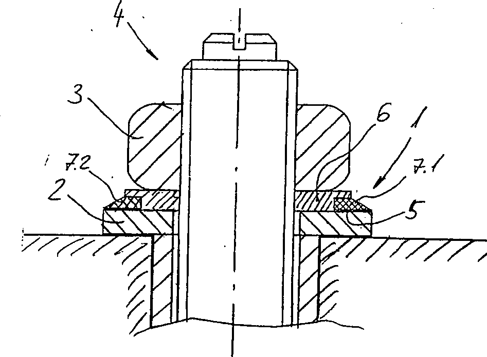
Beim
Verspannen des Dübelsystems
In
einer Variante der beschriebenen Messvorrichtung
Eine
Aufsicht auf ein zweites Ausführungsbeispiels
der erfindungsgemässen
Messvorrichtung zeigt die
Unter
dem transparenten Ringelement
Das
transparente Ringelement
In
Zusammenfassend ist festzustellen, dass mit der Erfindung eine Messvorrichtung und eine Befestigungsvorrichtung geschaffen wurde, die eine hohe Genauigkeit der visuellen Kontrolle der aufgebrachten Vorspannkraft auf das Befestigungsmittel aufweist und zudem universell einsetzbar sowie kostengünstig herstellbar ist. Des Weiteren ist eine Verschmutzung des sichtbaren Umgebungsbereichs des Befestigungsmittels durch Elemente der Messvorrichtung verhindert.In summary It should be noted that with the invention, a measuring device and a fastening device has been created which has a high accuracy the visual control of the applied biasing force on the Has fastening means and also universally applicable as well economical can be produced. Furthermore, there is a pollution of the visible Surrounding area of the fastener by elements of the measuring device prevented.
Claims (5)
Priority Applications (3)
| Application Number | Priority Date | Filing Date | Title |
|---|---|---|---|
| DE10316632A DE10316632B4 (en) | 2003-04-11 | 2003-04-11 | measuring device |
| US10/820,333 US7021153B2 (en) | 2003-04-11 | 2004-04-08 | Measuring device |
| JP2004115223A JP4719426B2 (en) | 2003-04-11 | 2004-04-09 | measuring device |
Applications Claiming Priority (1)
| Application Number | Priority Date | Filing Date | Title |
|---|---|---|---|
| DE10316632A DE10316632B4 (en) | 2003-04-11 | 2003-04-11 | measuring device |
Publications (2)
| Publication Number | Publication Date |
|---|---|
| DE10316632A1 DE10316632A1 (en) | 2004-11-11 |
| DE10316632B4 true DE10316632B4 (en) | 2005-09-22 |
Family
ID=33103325
Family Applications (1)
| Application Number | Title | Priority Date | Filing Date |
|---|---|---|---|
| DE10316632A Expired - Fee Related DE10316632B4 (en) | 2003-04-11 | 2003-04-11 | measuring device |
Country Status (3)
| Country | Link |
|---|---|
| US (1) | US7021153B2 (en) |
| JP (1) | JP4719426B2 (en) |
| DE (1) | DE10316632B4 (en) |
Cited By (2)
| Publication number | Priority date | Publication date | Assignee | Title |
|---|---|---|---|---|
| DE102010042263A1 (en) | 2010-10-11 | 2012-04-12 | Hilti Aktiengesellschaft | Sensor arrangement, for example on an anchor bolt |
| WO2012055600A1 (en) | 2010-10-29 | 2012-05-03 | Hilti Aktiengesellschaft | Load-indicating washer |
Families Citing this family (22)
| Publication number | Priority date | Publication date | Assignee | Title |
|---|---|---|---|---|
| US20080138167A1 (en) * | 2006-12-12 | 2008-06-12 | Ivan Wayne Wallace | Direct Tension Indicating Washers |
| US8092128B1 (en) * | 2007-02-20 | 2012-01-10 | Bray Alan V | Self-sealing fasteners |
| US7649469B2 (en) * | 2007-05-30 | 2010-01-19 | The Boeing Company | Pressure sensitive work indicator |
| FR2927166B1 (en) * | 2008-02-05 | 2012-03-16 | Peugeot Citroen Automobiles Sa | METHOD AND DEVICE FOR MONITORING ASSEMBLY OPERATION, APPLICATION TO MANUFACTURING LINES |
| JP2010127298A (en) * | 2008-11-25 | 2010-06-10 | Nippon Fastener Kogyo Kk | Washer |
| JP5500444B2 (en) * | 2010-06-08 | 2014-05-21 | 株式会社阪村機械製作所 | Screw fastening method |
| CA2816864A1 (en) | 2010-11-02 | 2012-05-10 | Systems And Materials Research Corporation | Method and apparatus for making and using a self-sealing fastener |
| DE202011111010U1 (en) * | 2011-01-03 | 2018-05-28 | Wolfgang B. Thörner | Polklemme |
| EP2492516A1 (en) * | 2011-02-22 | 2012-08-29 | Siemens Aktiengesellschaft | Marking element for identifying a tightening torque of a screw connection |
| US20130170924A1 (en) * | 2012-01-04 | 2013-07-04 | Applied Bolting Technology Products, Inc. | Direct Tension Indicating Washer With Centering Elements |
| DE102012201293A1 (en) * | 2012-01-31 | 2013-08-01 | Hilti Aktiengesellschaft | Anchor system, in particular undercut anchor system |
| US9541117B2 (en) | 2012-06-04 | 2017-01-10 | Manoj Handa | Torque-indication crush washer |
| US9239071B2 (en) * | 2014-03-18 | 2016-01-19 | Robert E. Stewart | Direct tension indicator plate and assembly |
| US11193523B2 (en) * | 2014-05-16 | 2021-12-07 | Applied Bolting Technology | Direct tension indicating washer with enhanced indicating material and method of manufacturing |
| US10648871B2 (en) * | 2017-10-05 | 2020-05-12 | International Business Machines Corporation | Fracture ring sensor |
| DE102018201134A1 (en) * | 2018-01-25 | 2019-07-25 | Bayerische Motoren Werke Aktiengesellschaft | A method of controlling collision damage to a workpiece, foil and use of dye-filled microcapsules |
| US10704975B2 (en) | 2018-03-09 | 2020-07-07 | General Electric Company | Visual torque indication for threaded joints |
| FR3092882B1 (en) * | 2019-02-19 | 2022-10-14 | Lionel Utille | DEVICE FOR VISUALIZING VOLTAGE LOSS IN AN ASSEMBLY |
| JP7321063B2 (en) * | 2019-11-19 | 2023-08-04 | フジモリ産業株式会社 | Rock bolt end fixing device in tunnel and state judgment method |
| ES2965301T3 (en) * | 2020-05-14 | 2024-04-12 | Sandvik Mining And Construction Tools Ab | A tension indicator for a rock bolt |
| CN112014023B (en) * | 2020-08-31 | 2021-06-01 | 湖北文理学院 | Hub bolt torque detection device |
| US12203499B1 (en) * | 2023-12-12 | 2025-01-21 | The Boeing Company | Fastening system, a fastener assembly, and a method of preloading the fastener assembly |
Citations (3)
| Publication number | Priority date | Publication date | Assignee | Title |
|---|---|---|---|---|
| DE3148730C2 (en) * | 1981-12-09 | 1991-05-16 | His Handels- Und Industriebedarf Gmbh, 4350 Recklinghausen, De | |
| DE69311897T2 (en) * | 1992-04-10 | 1997-10-16 | Stanley Ceney | FASTENING INDICATING FASTENER |
| DE69711184T2 (en) * | 1996-07-12 | 2002-10-31 | Clarke, Philomena | METHOD AND DEVICE FOR LOAD DISPLAY |
Family Cites Families (10)
| Publication number | Priority date | Publication date | Assignee | Title |
|---|---|---|---|---|
| DE7821489U1 (en) | 1978-10-26 | Siemens Ag, 1000 Berlin Und 8000 Muenchen | Screw with a screw head | |
| US3948141A (en) * | 1974-08-20 | 1976-04-06 | Katsumi Shinjo | Load indicating washer |
| JPS54140458A (en) * | 1978-04-24 | 1979-10-31 | Hitachi Ltd | Braun tube |
| GB8619910D0 (en) * | 1986-08-15 | 1986-09-24 | British Aerospace | Detection of damage in structural materials |
| JPS63293313A (en) * | 1987-05-26 | 1988-11-30 | 三菱電機株式会社 | Display unit for clamping force of joining section |
| FR2669735B2 (en) * | 1990-06-06 | 1993-02-19 | Hutchinson | METHOD AND DEVICE FOR EVIDENCE OF A SHOCK (S) RECEIVED BY A SUBSTRATE. |
| DE69311197T2 (en) * | 1992-03-19 | 1997-09-18 | Central Glass Co Ltd | Infrared and ultraviolet radiation absorbing, neutral gray colored glass |
| JPH0755606A (en) * | 1993-08-06 | 1995-03-03 | Brother Ind Ltd | Pressure measurement sheet |
| US6425718B1 (en) * | 2000-07-11 | 2002-07-30 | Applied Bolting Technology Products Inc. | Direct multi-tension indicating washer having bumps of a first and second height |
| CA2366168A1 (en) * | 2001-12-24 | 2003-06-24 | Ipex Inc. | Colour pressure-sensitive fastener |
-
2003
- 2003-04-11 DE DE10316632A patent/DE10316632B4/en not_active Expired - Fee Related
-
2004
- 2004-04-08 US US10/820,333 patent/US7021153B2/en not_active Expired - Lifetime
- 2004-04-09 JP JP2004115223A patent/JP4719426B2/en not_active Expired - Lifetime
Patent Citations (3)
| Publication number | Priority date | Publication date | Assignee | Title |
|---|---|---|---|---|
| DE3148730C2 (en) * | 1981-12-09 | 1991-05-16 | His Handels- Und Industriebedarf Gmbh, 4350 Recklinghausen, De | |
| DE69311897T2 (en) * | 1992-04-10 | 1997-10-16 | Stanley Ceney | FASTENING INDICATING FASTENER |
| DE69711184T2 (en) * | 1996-07-12 | 2002-10-31 | Clarke, Philomena | METHOD AND DEVICE FOR LOAD DISPLAY |
Cited By (6)
| Publication number | Priority date | Publication date | Assignee | Title |
|---|---|---|---|---|
| DE102010042263A1 (en) | 2010-10-11 | 2012-04-12 | Hilti Aktiengesellschaft | Sensor arrangement, for example on an anchor bolt |
| WO2012048933A1 (en) | 2010-10-11 | 2012-04-19 | Hilti Aktiengesellschaft | Sensor arrangement, for example on an anchor bolt |
| US9417169B2 (en) | 2010-10-11 | 2016-08-16 | Hilti Aktiengesellschaft | Sensor arrangement, for example, on an anchor bolt |
| WO2012055600A1 (en) | 2010-10-29 | 2012-05-03 | Hilti Aktiengesellschaft | Load-indicating washer |
| CN103180623A (en) * | 2010-10-29 | 2013-06-26 | 喜利得股份公司 | Load-indicating washer |
| CN103180623B (en) * | 2010-10-29 | 2015-08-19 | 喜利得股份公司 | Load indicating gasket and the concrete anchor with this load indicating gasket |
Also Published As
| Publication number | Publication date |
|---|---|
| JP2004317510A (en) | 2004-11-11 |
| US20040200290A1 (en) | 2004-10-14 |
| US7021153B2 (en) | 2006-04-04 |
| DE10316632A1 (en) | 2004-11-11 |
| JP4719426B2 (en) | 2011-07-06 |
Similar Documents
| Publication | Publication Date | Title |
|---|---|---|
| DE10316632B4 (en) | measuring device | |
| DE69610957T2 (en) | Sealing fastener | |
| DE60126028T2 (en) | Adhesive fixated anchoring element and anchoring system | |
| DE69402090T2 (en) | Clamping device | |
| DE2517613B2 (en) | Downhole tool and method for attaching and detaching a downhole tool to or from a drill string | |
| DE60132933T2 (en) | Device for directional drilling | |
| EP0544613A1 (en) | Self-threading screw | |
| DE102017108664A1 (en) | Expansion sleeve anchor with lost drill bit | |
| WO2008006345A2 (en) | Dowel composed of a strand arrangement | |
| DE2654727A1 (en) | DOWEL WITH SPREADING SLEEVE AND SPREADING BODY | |
| DE69111933T2 (en) | Method and device for injecting a restoration agent into concrete. | |
| DE2254550C3 (en) | Bracket for climbing elements | |
| EP0546990A1 (en) | Dowel for increasing the anchoring value of a screw | |
| DE10229141C1 (en) | Concrete nail for power drive fastening has nail guided in washer with sleeve receiving force direction shaft of nail | |
| EP0475891A1 (en) | Method and means for making holes | |
| EP1693578B1 (en) | Fastening-anchor and use of same | |
| DE102018100493A1 (en) | Washer, washer assembly and washer | |
| DE102005016097A1 (en) | Fixing anchor | |
| EP0122924B1 (en) | Injection device | |
| DE3408093A1 (en) | Drill bit | |
| DE60204465T2 (en) | SCREW WITH SEAL | |
| EP0930438B1 (en) | Thread tapping screw | |
| DE69604683T2 (en) | NUT FOR MOUNTAIN ANCHOR ARRANGEMENT | |
| DE2208280A1 (en) | Tensioning device for screw bolts | |
| DE2633274C2 (en) | Cable or pipe clamp |
Legal Events
| Date | Code | Title | Description |
|---|---|---|---|
| OP8 | Request for examination as to paragraph 44 patent law | ||
| 8364 | No opposition during term of opposition | ||
| 8327 | Change in the person/name/address of the patent owner |
Owner name: HILTI AKTIENGESELLSCHAFT, SCHAAN, LI |
|
| R119 | Application deemed withdrawn, or ip right lapsed, due to non-payment of renewal fee |