DE10222041B4 - Afocal zoom system for use in microscopes - Google Patents
Afocal zoom system for use in microscopes Download PDFInfo
- Publication number
- DE10222041B4 DE10222041B4 DE10222041A DE10222041A DE10222041B4 DE 10222041 B4 DE10222041 B4 DE 10222041B4 DE 10222041 A DE10222041 A DE 10222041A DE 10222041 A DE10222041 A DE 10222041A DE 10222041 B4 DE10222041 B4 DE 10222041B4
- Authority
- DE
- Germany
- Prior art keywords
- zoom
- zoom system
- magnification
- enp
- focal length
- Prior art date
- Legal status (The legal status is an assumption and is not a legal conclusion. Google has not performed a legal analysis and makes no representation as to the accuracy of the status listed.)
- Expired - Lifetime
Links
Classifications
-
- G—PHYSICS
- G02—OPTICS
- G02B—OPTICAL ELEMENTS, SYSTEMS OR APPARATUS
- G02B21/00—Microscopes
- G02B21/18—Arrangements with more than one light path, e.g. for comparing two specimens
- G02B21/20—Binocular arrangements
- G02B21/22—Stereoscopic arrangements
-
- G—PHYSICS
- G02—OPTICS
- G02B—OPTICAL ELEMENTS, SYSTEMS OR APPARATUS
- G02B15/00—Optical objectives with means for varying the magnification
- G02B15/14—Optical objectives with means for varying the magnification by axial movement of one or more lenses or groups of lenses relative to the image plane for continuously varying the equivalent focal length of the objective
- G02B15/144—Optical objectives with means for varying the magnification by axial movement of one or more lenses or groups of lenses relative to the image plane for continuously varying the equivalent focal length of the objective having four groups only
- G02B15/1441—Optical objectives with means for varying the magnification by axial movement of one or more lenses or groups of lenses relative to the image plane for continuously varying the equivalent focal length of the objective having four groups only the first group being positive
- G02B15/144105—Optical objectives with means for varying the magnification by axial movement of one or more lenses or groups of lenses relative to the image plane for continuously varying the equivalent focal length of the objective having four groups only the first group being positive arranged +-+-
-
- G—PHYSICS
- G02—OPTICS
- G02B—OPTICAL ELEMENTS, SYSTEMS OR APPARATUS
- G02B21/00—Microscopes
- G02B21/02—Objectives
- G02B21/025—Objectives with variable magnification
Abstract
Afokales
Zoomsystem (1) zur Verwendung in Mikroskopen mit einer Tubuslinse
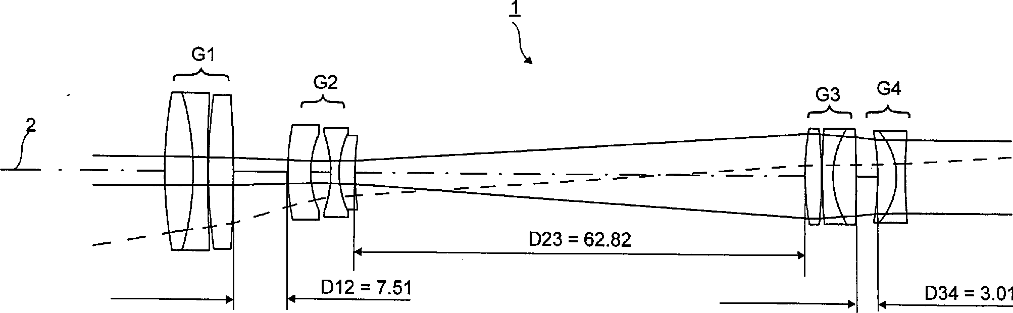
(11), wobei das Zoomsystem von der Objektseite aus gesehen aus vier aufeinanderfolgenden
optischen Baugruppen (G1, G2, G3, G4) besteht, wobei die erste Baugruppe
(G1) eine positive Brennweite (f1), die zweite Baugruppe (G2) eine
negative Brennweite (f2), die dritte Baugruppe (G3) eine positive Brennweite
(f3) und die vierte Baugruppe (G4) eine negative Brennweite (f4)
aufweist und die erste und vierte Baugruppe (G1, G4) ortsfest angeordnet
sind, und wobei zur Veränderung
der Vergrößerung des
Zoomsystems (1) die zweite und dritte Baugruppe (G2, G3) beweglich
angeordnet sind, wobei die Zoomvergrößerung mit zunehmendem Abstand
(D23) zwischen den beiden Baugruppen (G2, G3) abnimmt, dadurch gekennzeichnet,
daß für den Zoomfaktor
z gilt z > 15, und
daß die
Vergrösserung
(VZO) des Zoomsystems folgende Bedingung erfüllt:
Description
Die Erfindung betrifft ein afokales Zoomsystem zur Verwendung in Mikroskopen mit einer Tubuslinse, wobei das Zoomsystem von der Objektseite aus gesehen aus vier aufeinanderfolgenden optischen Baugruppen besteht, wobei die erste Gruppe eine positive Brennweite, die zweite Gruppe eine negative Brennweite, die dritte Baugruppe eine positive Brennweite und die vierte Baugruppe eine negative Brennweite aufweist, und wobei die erste und die vierte Baugruppe ortsfest angeordnet sind und zur Veränderung der Vergrößerung des Zoomsystems die zweite und dritte Baugruppe beweglich angeordnet sind, wobei die Zoomvergrößerung mit wachsendem Abstand zwischen der zweiten und der dritten Baugruppe abnimmt. Die Erfindung betrifft weiterhin ein Mikroskop sowie ein Stereomikroskop mit einem solchen afokalen Zoomsystem.The The invention relates to an afocal zoom system for use in microscopes with a tube lens, with the zoom system from the object side consists of four consecutive optical assemblies, where the first group has a positive focal length, the second group a negative focal length, the third module a positive focal length and the fourth assembly has a negative focal length, and wherein the first and the fourth assembly are arranged stationary and to change the enlargement of the Zoomsystems the second and third assembly arranged movably are, where the zoom magnification with increasing distance between the second and the third assembly decreases. The invention further relates to a microscope and a Stereomicroscope with such an afocal zoom system.
Mikroskope, insbesondere Stereomikroskope, mit einem afokalen Zoomsystem der genannten Art werden überall dort eingesetzt, wo eine hohe Objektvergrößerung vorausgesetzt ist, wie in Technologie-Unternehmen zur Manipulation und zur Inspektion kleiner Objekte, wie beispielsweise Halbleiterstrukturen oder mikromechanische Objekte, in Forschungsinstituten der Biowissenschaften und der Materialkunde sowie beispielsweise zur Untersuchung und Manipulation von Zellen oder auch zu operativen Zwecken. Im Zuge der Miniaturisierung und der Erforschung immer kleinerer Präparate steigen einerseits die Anforderungen an die Auflösung dieser Mikroskope, andererseits gewinnt die Größe des Ge sichtsfeldes bei schwacher Vergrößerung zum schnellen Positionieren der Präparate und zur verbesserten Übersicht bei Inspektionen an Bedeutung.microscopes, in particular stereomicroscopes, with an afocal zoom system of type mentioned will be everywhere used where a high object magnification is required, such as in technology companies to manipulate and inspect small Objects, such as semiconductor structures or micromechanical Objects, in research institutes of the life sciences and materials science as well as for examining and manipulating cells or for operational purposes. In the course of miniaturization and On the one hand, research into ever smaller preparations is increasing Resolution requirements On the other hand, the size of the field of view is getting weaker Magnification to fast positioning of the preparations and for improved overview important for inspections.
Um bei einem Mikroskop die Vergrößerung zu erhöhen und diese über einen bestimmten Bereich stufenlos verändern zu können, werden diese mit einem Zoomsystem ausgestattet. Ein afokales Zoomsystem bildet ein Objekt im Unendlichen in ein im Unendlichen liegendes Bild ab. Bezeichnet man mit wE den Winkel zur optischen Achse, unter dem ein Objektpunkt im Unendlichen erscheint, und mit wA den Austrittswinkel nach Durchgang durch das Zoomsystem unter dem der Bildpunkt im Unendlichen erscheint, so beträgt die Vergrößerung des Zoomsystems VZO = tan(wA)/tan(wE). Das Zoomsystem erlaubt eine Vergrößerungsvariation ohne Veränderung der Objekt- und der Bildlage. Das Verhältnis von maximaler zu minimaler Zoomvergrößerung wird Zoomfaktor z genannt.Around magnification in a microscope increase and these over To be able to change a certain area infinitely, these are with a Zoom system equipped. An afocal zoom system forms an object at infinity into an infinite image. Designated with wE the angle to the optical axis, below which an object point appears at infinity, and with wA the exit angle after passage through the zoom system under which the pixel appears at infinity, so is the enlargement of the Zoom systems VZO = tan (wA) / tan (wE). The zoom system allows a magnification variation without change the object and the picture position. The relationship from maximum to minimum zoom magnification is called z zoom factor.
Wie
in
Mit
ENP ist der Durchmesser der Eintrittspupille des Zoomsystems
Die
beiden Zwischenbilder
Mit
EP wird wiederum der Durchmesser der Eintrittspupille des Zoomsystems
benannt, wobei EP für beide,
in gleicher Weise verstellbare Zoomsysteme
In
dem bereits oben erwähnten
Artikel von K.-P. Zimmer "Optical
Designs for Stereomicroscopes" (1998)
ist ein Zoomsystem für
ein oben beschriebenes Stereomikroskop vorgestellt, wie es in
Das
in
Nachteil
der in
Die Druckschrift DE 26 40 454 OS behandelt eine Fassung für ein Varioobjektiv zur Verwendung in Fotoapparaten, nämlich zum Umstellen vom Fernaufnahmebereich auf den Nahaufnahmebereich. Aus diesem Dokument geht ein Zoomsystem mit vier, abwechselnd positiven und negativen Baugruppen hervor. Die mit einem solchen System realisierten Zoomfaktoren und Eintrittspupillendurchmesser liegen weit unterhalb derjenigen Werte, die für ein Zoomsystem zur Verwendung in einem hoch auflösenden Mikroskop realisiert werden müssen. Die Bauweise von Zoomsystemen für Hochleistungsmikroskope unterscheiden sich deutlich von denen für Aufnahmeobjektive in Fotoapparaten.The Document DE 26 40 454 OS deals with a version for a zoom lens for use in cameras, namely for switching from the telephoto range on the closeup area. From this document goes a zoom system with four, alternating positive and negative modules. The zoom factors and entrance pupil diameter realized with such a system are far below those values that are suitable for a zoom system in a high resolution Microscope must be realized. The construction of zoom systems for High-performance microscopes differ significantly from those for recording lenses in cameras.
Schließlich ist
aus der
Das
Zoomsystem gemäß
Aufgabe vorliegender Erfindung ist daher, ein afokales Zoomsystem der eingangs genannten Art für hochauflösende Mikroskope mit hohem Zoomfaktor anzugeben, der eine kontinuierlich veränderbare Vergrößerung über einen möglichst großen Bereich bei gleichzeitig größtmöglicher Auflösung ermöglicht. Zudem sollen die Anforderungen nach wachsenden Gesichtsfeldern erfüllt sein.task The present invention is therefore an afocal zoom system of the beginning mentioned type for high-resolution microscopes specify a high zoom factor, which is a continuously variable Magnification over one preferably huge Area with at the same time largest possible resolution allows. In addition, the requirements for growing visual fields should be met.
Diese Aufgabe wird durch die Merkmale der unabhängigen Ansprüche 1 oder 2 bzw. 12 oder 13 erfüllt. Vorteilhafte Ausgestaltungen ergeben sich aus den jeweiligen Unteransprüchen sowie der nachfolgenden Beschreibung.These The object is achieved by the features of the independent claims 1 or 2 or 12 or 13 fulfilled. advantageous Embodiments emerge from the respective subclaims as well the following description.
Die Bedingung VZO ≤ 41 × ENP/fT, im folgenden mit (B1) bezeichnet, gibt für die Zoomvergrößerung eine Obergrenze an, die proportional ist zum Verhältnis des Durchmessers ENP der Zoomeintrittspupille bei maximaler Vergrößerung des Zoomsystems zur Brennweite fT der Tubuslinse des Mikroskops. Somit werden die Leistungsdaten des Zoomsystems mit optischen Größen des Mikroskops verknüpft. Die Erfüllung von (B1) garantiert, daß die starke Mikroskopvergrößerung im Bereich der förderlichen Vergrößerung liegt und begrenzt den Kontrastabfall bei kleinen Austrittspupillen.The Condition VZO ≤ 41 × ENP / fT, hereinafter referred to as (B1), there is a zoom magnification Upper limit, which is proportional to the ratio of the diameter ENP of the zoom entrance pupil at maximum magnification of the zoom system Focal length fT of the tube lens of the microscope. Thus, the performance data of the zoom system with optical sizes of Linked microscope. The fulfillment of (B1) guarantees that the strong microscope magnification in the Area of beneficial Magnification is and limits the contrast drop in small exit pupils.
Als „förderliche Vergrößerung" eines Mikroskops ist der Bereich derjenigen Mikroskopvergrößerung definiert, innerhalb dessen alle Objektstrukturen aufgelöst, vergrößert abgebildet und vom menschlichen Auge erkannt werden. Eine höhere Vergrößerung ist zwar möglich, aber nicht förderlich, da keine weiteren Einzelheiten erkennbar werden, die vom Mikroskopobjektiv wegen begrenzter Auflösung nicht abgebildet werden können (sog. „leere Vergrößerung", bei der sich zwar ein größeres Bild, aber keine feineren Strukturen ergeben). Die Detailerkennbarkeit hängt weiterhin vom Kontrast des Bildes ab. Hierbei spielt der Austrittspupillendurchmesser des Mikroskops eine Rolle, da bei zunehmendem Durchmesser hellere Bilder geliefert werden und der Kontrastverlust durch Beugung im Auge und Unregelmäßigkeiten im Glaskörper des Auges verringert wird.As "beneficial Magnification "of a microscope is the range of those microscope magnification defined within whose all object structures are resolved, magnified and represented by the human Eye can be detected. A higher one Magnification is while possible, but not conducive, since no further details are recognizable, that of the microscope objective because of limited resolution can not be displayed (so-called "empty Magnification ", which is indeed a bigger picture, but no finer structures result). The detail recognition hangs on from the contrast of the picture. Here, the exit pupil diameter plays of the microscope, as brighter as the diameter increases Pictures are supplied and the contrast loss due to diffraction in the Eye and irregularities in the vitreous of the eye is reduced.
Die Erfüllung der erfindungsgemäßen Bedingung (B1) stellt für hochauflösende Mikroskope mit ENP > 21mm nun sicher, daß mit wachsender Zoomvergrößerung VZO auch die Detailerkennbarkeit steigt, und daß gleichzeitig der Kontrastabfall, der der Detailerkennbarkeit entgegenwirkt, begrenzt bleibt.The fulfillment of the condition (B1) according to the invention for high-resolution microscopes with ENP> 21 mm now ensures that with increasing zoom magnification VZO also the detail recognition increases, and that at the same time the contrast drop counteracting the detail recognition remains limited.
Während (B1)
eine Bedingung an das afokale Zoomsystem bei maximaler Vergrößerung definiert,
gibt die nachfolgende Bedingung (B2) eine Anforderung an das Zoomsystem
bei niedrigster Vergrößerung an.
Erfindungsgemäß lautet
(B2): tan(w1) ≥ 0.268 × z/ENP.
Hierbei ist w1, wie aus
Vorteilhaft ist eine gleichzeitige Erfüllung der Bedingungen (B1) und (B2), da dann sichergestellt ist, daß beim Arbeiten mit dem erfindungsgemäßen Zoomsystem die Mikroskopvergrößerung im Bereich der förderlichen Vergrößerung liegt, und daß bei niedrigen Vergrößerungen ein großes Gesichtsfeld und bei höchsten Vergrößerungen eine ausreichende Auflösung verfügbar ist.Advantageous is a simultaneous fulfillment the conditions (B1) and (B2), because then it is ensured that when working with the zoom system according to the invention the microscope magnification in the Area of beneficial Magnification is, and that at low magnifications a big Field of vision and at the highest magnifications a sufficient resolution available is.
Es hat sich als vorteilhaft erwiesen, wenn der Durchmesser der Zoomeintrittspupille bei maximaler Vergrößerung der Bedingung 21 mm < ENP ≤ 27 mm genügt. Derartige Eintrittspupillendurchmesser eignen sich in der Praxis zur Erfüllung der Bedingung (B1) besonders gut. Größere Eintrittspupillendurchmesser führen in der Praxis, insbesondere bei Stereomikroskopen, zu hohen baulichen Abmessungen und zudem zu stärker werdenden optischen Abbildungsfehlern. Auf der anderen Seite führen kleinere Eintrittspupillendurchmesser zu verringerter Auflösung.It has proved to be advantageous when the diameter of the zoom entrance pupil at maximum magnification of Condition 21 mm <ENP ≤ 27 mm is sufficient. such Entry pupil diameter are suitable in practice to fulfill the Condition (B1) especially good. Larger entrance pupil diameter to lead in practice, especially in stereomicroscopes, too high structural Dimensions and also becoming stronger optical aberrations. On the other hand, smaller ones lead Entry pupil diameter to reduced resolution.
Weiterhin ist für den Zoomfaktor z die Erfüllung der Bedingung 15 < z ≤ 20 vorteilhaft. Im Zusammenhang mit den Bedingungen (B1) und (B2) ist bei diesen Zoomfaktoren ein Arbeiten im Bereich der förderlichen Vergrößerung bei genügend großem Gesichtfeld im Bereich niedriger Vergrößerung in der Praxis gut erzielbar.Farther is for the zoom factor z the fulfillment the condition 15 <z ≦ 20 advantageous. In connection with the conditions (B1) and (B2) is in these Zoom factors contribute to a work in the field of beneficial magnification enough great Field of view in the range of low magnification in practice easily achievable.
Die
Baulänge
des Zoomsystems ist aus ergonomischen wie auch aus herstellungstechnischen
Gründen
von großer
Bedeutung. Ein langes Zoomsystem bewirkt eine große Bauhöhe des Mikroskops
und erschwert einen ermüdungsfreien
Einblick. Große
Eintrittspupillendurchmesser EP und große Zoomfaktoren z sind in Zoomsystemen
kurzer Baulänge
nur schwer zu realisieren. Es hat sich bei den erfindungsgemäßen Zoomsystemen
als vorteilhaft erwiesen, die Zoomlänge L durch folgende Bedingung
(B3) nach oben zu beschränken:
Hochauflösende Mikroskope
bedingen nach dem oben beschriebenen einen großen Eintrittspupillendurchmesser
ENP des Zoomsystems bei maximaler Zoomvergrößerung. Um dennoch eine kurze
Baulänge des
Zoomsystems realisieren zu können,
ist die Konstruktion der Baugruppe G1 vorteilhaft so zu gestalten, daß die Brennweite
f1 der Baugruppe G1 trotz großem
ENP klein bleibt. Als besonders günstige Bedingung (B4) kann
die folgende Ungleichung aufgestellt werden:
Es werden Ausführungsbeispiele erfindungsgemäßer Zoomsysteme vorgestellt, die die Bedingung (B4) bei einer Obergrenze von 3,3 anstelle 3,5 erfüllen und somit vorteilhaft zu einer kurzen Baulänge und guter Abbildungsleistung bei großen ENPs beitragen.It Be exemplary embodiments zoom systems according to the invention presented the condition (B4) with an upper limit of 3.3 instead of 3.5 and thus advantageous to a short length and good imaging performance at big ENPs contribute.
Eine nach oben begrenzte Linsenzahl ist fertigungtechnisch vorteilhaft und begrenzt die Kosten. Erfindungsgemäße Zoomsysteme mit maximal elf Linsen sind in dieser Hinsicht besonders günstig.An upwardly limited number of lenses is advantageous in terms of production and limits the costs. OF INVENTION According to the present zoom systems with a maximum of eleven lenses are particularly favorable in this regard.
Besonders vorteilhaft ist es für die Herstellkosten des Zoomsystems, wenn die Baugruppe G4 aus maximal zwei miteinander verkitteten Linsen besteht. Weiterhin ist es für die Baugruppe G1 sinnvoll, diese aus einem Kittglied mit nachfolgender Einzellinse aufzubauen, wobei das Kittglied aus zwei miteinander verkitteten Linsen besteht, und wobei die Einzellinse bikonvex ist und im Kittglied die Linse mit positiver Brechkraft zum Objekt zeigt.Especially it is advantageous for the manufacturing costs of the zoom system, if the assembly G4 from maximum consists of two cemented lenses. Furthermore, it is for the assembly G1 makes sense, this from a cemented component with subsequent single lens build up, wherein the cemented element of two cemented together lenses and wherein the single lens is biconvex and in the cemented component shows the lens with positive refractive power to the object.
Eine besonders günstige Ausführungsform eines erfindungsgemäßen afokalen Zoomsystems gibt Tabelle 1 zum Ausführungsbeispiel 1 an. Diese Ausführungsform wird weiter unten noch näher beschrieben.A especially cheap embodiment an afocal according to the invention Zoomsystems gives Table 1 to Embodiment 1. These embodiment will be even closer below described.
Im folgenden sollen anhand der beigefügten Zeichnungen Ausführungsbeispiele die Erfindung und deren Vorteile näher erläutern.in the The following are exemplary embodiments with reference to the accompanying drawings explain the invention and its advantages in more detail.
Es zeigenIt demonstrate
Die
Erste AusführungsformFirst embodiment
Das
in
Hieraus ergibt sich für die Bedingung (B1): VZO ≤ 41 × ENP/fT = 41 × 22,5 mm/160 mm = 5,77, so daß das Zoomsystem mit seiner Maximalvergrößerung von 5,66 die Bedingung (B1) erfüllt.From this arises for the condition (B1): VZO ≦ 41 × ENP / fT = 41 × 22.5 mm / 160 mm = 5.77, so that the Zoom system with its maximum magnification of 5.66 the condition (B1) fulfilled.
Für die zweite Bedingung (B2) ergibt sich: tan(w1) = 0,20 ≥ 0,268 × z/ENP = 0,268 × 16/22,5 = 0,19, so daß auch die Bedingung (B2) erfüllt ist.For the second Condition (B2) gives: tan (w1) = 0.20 ≥0.268 × z / ENP = 0.268 × 16 / 22.5 = 0.19, so that too the condition (B2) is fulfilled is.
Das
Verhältnis
der Baulänge
L des Zoomsystems
Mit
einer Brennweite f1 = 73,06 mm für
die optische Baugruppe G1 des Zoomsystems
Zusammenfassend lässt sich feststellen, daß für die dargestellte Ausführungsform alle vier Bedingungen (B1) bis (B4) erfüllt werden, so daß das erfindungsgemäße Zoomsystem eine starke Mikroskopvergrößerung garantiert, die im Bereich der förderlichen Vergrößerung liegt, und die Betrachtung des Objektbildes bei einem nutzbaren Sehfelddurchmesser von 22 mm bei ausreichendem Kontrast ermöglicht. Die Baulänge des Zoomsystems ist mit L = 120 mm kleiner als vergleichbare Zooms und somit ausreichend klein, um eine ergonomisch und herstellungstechnisch günstige Bauhöhe des Mikroskops sicherzustellen. Dies wird auch durch die relativ kurze Brennweite von f1 = 73,06 mm bei ENP = 22,5 mm unterstützt.In summary let yourself find that for the illustrated embodiment all four conditions (B1) to (B4) are met, so that the zoom system according to the invention a strong microscope magnification guaranteed, those in the field of beneficial Magnification is, and viewing the subject image with a usable field of view diameter of 22 mm with sufficient contrast. The length of the zoom system is smaller with L = 120 mm than comparable zooms and thus sufficient small, ergonomically and manufacturing technically favorable height of the microscope sure. This is also due to the relatively short focal length supported by f1 = 73.06 mm at ENP = 22.5 mm.
Wie
aus
Tabelle
1 
In den Zeilen der Tabelle sind von links nach rechts die Flächennummer, der Krümmungsradius, der Abstand zur nächsten Fläche, die Brechzahl nd, die Dispersion νd und die partiellen Teildispersionen Pg,F und PC,t aufgelistet. Es bedeuten nd der Brechungsindex, νd = (nd –1) / (nF – nC) die Abbezahl, Pg,F = (ng – nF) / (nF – nC) die relative Teildispersion für die Wellenlängen g und F, und PC,t = (nC – nt) / (nF – nC) die relative Teildispersion für die Wellenlängen C und t. Ein Luftabstand ist durch eine Leerzeile in der Materialangabe gekennzeichnet. D1, D2 und D3 sind die veränderlichen Abstände.In the rows of the table are from left to right the area number, the radius of curvature, the distance to the next area, the refractive index n d , the dispersion ν d and the partial partial dispersions P g, F and P C, t listed. Let n d be the refractive index, ν d = (n d -1) / (n F -n C ) the Abbe number, P g, F = (n g -n F ) / (n F -n C ) the relative partial dispersion for the wavelengths g and F, and P C, t = (n C -n t ) / (n F -n C ) the relative partial dispersion for the wavelengths C and t. An air gap is indicated by a blank line in the material specification. D1, D2 and D3 are the variable distances.
Die Wellenlängen sind hierbei wie folgt definiert: die gelbe Heliumlinie d mit λ = 587,56 nm, die blaue Quecksilberlinie g mit λ = 435,83 nm, die blaue Wasserstofflinie F mit λ = 486,13 nm, die rote Wasserstofflinie C mit λ = 656,27 nm und die infrarote Quecksilberlinie t mit λ = 1013,98 nm.The wavelength are defined as follows: the yellow helium line d with λ = 587.56 nm, the blue mercury line g with λ = 435.83 nm, the blue hydrogen line F with λ = 486.13 nm, the red hydrogen line C with λ = 656.27 nm and the infrared Mercury line t with λ = 1013.98 nm.
Das Zoomsystem hat eine gute Korrektion des Öffnungsfehlers (sphärische Aberration) und eine gute Korrektion der Farbfehler (chromatische Aberration), insbesondere eine deutliche Reduktion des sekundären Spektrums, wie am Verlauf der Aberrationskurven für die Wellenlänge 435,83 nm zu erkennen ist. Astigmatismus, Bildfeldwölbung und Verzeichnung sind so gestaltet, daß eine Kompensation der üblichen Abbildungsfehler von Tubuslinse und Okular erfolgt. Der bereits beschriebene Aufbau der optischen Baugruppe G1 ermöglich es, einerseits den Öffnungsfehler bei großem Durchmesser ENP im Falle maximaler Vergrößerung und andererseits den Astigmatismus für einen großen Feldwinkel w1 im Falle der schwächsten Vergrößerung zu korrigieren. Durch eine geeignete Anordnung einer Blende im Zoomsystem lässt sich vorteilhaft erreichen, daß bei einer Erhöhung der Vergrößerung VZO die numerische Apertur des Mikroskops und damit die, wie oben ausgeführt, daran gekoppelte Auflösung des Mikroskops stetig steigt.The Zoom system has a good correction of the aperture error (spherical aberration) and a good correction of color aberrations (chromatic aberration), in particular a significant reduction of the secondary spectrum, as on the course the aberration curves for the wavelength 435.83 nm can be seen. Astigmatism, field curvature and Distortion are designed so that a compensation of the usual Aberration of tube lens and eyepiece done. That already described construction of the optical assembly G1 makes it possible on the one hand the opening error at large Diameter ENP in case of maximum magnification and on the other hand the Astigmatism for a big Field angle w1 in the case of the weakest Magnification too correct. By a suitable arrangement of a diaphragm in the zoom system let yourself achieve advantageous that at an increase the magnification VZO the numerical aperture of the microscope and thus, as stated above, to it coupled resolution of the microscope steadily rising.
Zweite AusführungsformSecond embodiment
Die
Hieraus berechnet sich für die Bedingung (B1): VZO ≤ 41 × ENP/fT = 41 × 27/160 = 6,92, so daß die Maximalvergrößerung von VZO = 5,66 diese Bedingung erfüllt. Weiterhin gilt tan(w1) = 0,20 ≥ 0,268 × 16/27 = 0,16, was der Bedingung (B2) genügt.From this, for the condition (B1): VZO ≦ 41 × ENP / fT = 41 × 27/160 = 6.92, so that the Maximum magnification of VZO = 5.66 satisfies this condition. Furthermore, tan (w1) = 0.20 ≥ 0.268 × 16/27 = 0.16, which satisfies the condition (B2).
Die
Baulänge
des in
Nachfolgende
Tabelle 2 gibt die numerischen Daten des Zoomsystems aus
Tabelle
2 
In den Zeilen der Tabelle sind von links nach rechts die Flächennummer, der Krümmungsradius, der Abstand zur nächsten Fläche, die Brechzahl nd, die Dispersion νd und die partiellen Teildispersionen Pg,F und PC,t aufgelistet. Es bedeuten nd der Brechungsindex, νd = (nd – 1) / (nF – nC) die Abbezahl, Pg,F = (ng – nF) / (nF – nC) die relative Teildispersion für die Wellenlängen g und F, und PC,t = (nC – nt) / (nF – nC) die relative Teildispersion für die Wellenlängen C und t. Ein Luftabstand ist durch eine Leerzeile in der Materialangabe gekennzeichnet. D1, D2 und D3 sind die veränderlichen Abstände.In the rows of the table are from left to right the area number, the radius of curvature, the distance to the next area, the refractive index n d , the dispersion ν d and the partial partial dispersions P g, F and P C, t listed. N d is the refractive index, ν d = (n d -1) / (n F -n C ) the Abbe number, P g, F = (n g -n F ) / (n F -n C ) the relative partial dispersion for the wavelengths g and F, and P C, t = (n C -n t ) / (n F -n C ) the relative partial dispersion for the wavelengths C and t. An air gap is indicated by a blank line in the material specification. D1, D2 and D3 are the variable distances.
Dritte AusführungsformThird embodiment
- (B1) VZO ≤ 41 × ENP/fT = 41 × 27/160 = 6,92. Mit einer Maximalvergrößerung von VZO = 6,76 wird die Obergrenze von (B1) unterschritten.
- (B2) tan(w1) = 0,2 ≥ 0,268 × z/ENP = 0,268 × 20/27 = 0,20, so daß auch der Bedingung (B2) genüge getan ist.
- (B1) VZO ≦ 41 × ENP / fT = 41 × 27/160 = 6.92. With a maximum magnification of VZO = 6.76, the upper limit of (B1) is exceeded.
- (B2) tan (w1) = 0.2 ≥0.268 × z / ENP = 0.268 × 20/27 = 0.20, so that the condition (B2) is also satisfied is.
Die
Baulänge
des Zoomsystems beträgt
in diesem Fall 140 mm, so daß gilt
L/ENP = 5,19 ≤ 1,37 × √
Zu
den aus der Erfüllung
der genannten Bedingungen sich ergebenden Vorteilen gilt das bereits
oben Ausgeführte.
Nachfolgende Tabelle gibt die numerischen Daten des in
Tabelle
3 
In den Zeilen der Tabelle sind von links nach rechts die Flächennummer, der Krümmungsradius, der Abstand zur nächsten Fläche, die Brechzahl nd, die Dispersion νd und die partiellen Teildispersionen Pg,F und PC,t aufgelistet. Es bedeuten nd der Brechungsindex, νd = (nd – 1) / (nF – nC) die Abbezahl, Pg,F = (ng – nF) / (nF – nC) die relative Teildispersion für die Wellenlängen g und F, und PC, t = (nC – nt) / (nF – nC) die relative Teildispersion für die Wellenlängen C und t. Ein Luftabstand ist durch eine Leerzeile in der Materialangabe gekennzeichnet. D1, D2 und D3 sind die veränderlichen Abstände.In the rows of the table are from left to right the area number, the radius of curvature, the distance to the next area, the refractive index n d , the dispersion ν d and the partial partial dispersions P g, F and P C, t listed. N d is the refractive index, ν d = (n d -1) / (n F -n C ) the Abbe number, P g, F = (n g -n F ) / (n F -n C ) the relative partial dispersion for the wavelengths g and F, and P C, t = (n C -n t ) / (n F -n C ) the relative partial dispersion for the wavelengths C and t. An air gap is indicated by a blank line in the material specification. D1, D2 and D3 are the variable distances.
Vierte AusführungsformFourth embodiment
- (B1)
- (B2)
- (B3)
- (B4)
- (B1)
- (B2)
- (B3)
- (B4)
Somit
vereint auch das in
Tabelle
4 
In den Zeilen der Tabelle sind von links nach rechts die Flächennummer, der Krümmungsradius, der Abstand zur nächsten Fläche, die Brechzahl nd, die Dispersion νd und die partiellen Teildispersionen Pg,F und PC,t aufgelistet. Es bedeuten nd der Brechungsindex, νd = (nd – 1) / (nF – nC) die Abbezahl, Pg,F = (ng – nF) / (nF – nC) die relative Teildispersion für die Wellenlängen g und F, und PC,t = (nC – nt) / (nF – nC) die relative Teildispersion für die Wellenlängen C und t. Ein Luftabstand ist durch eine Leerzeile in der Materialangabe gekennzeichnet. D1, D2 und D3 sind die veränderlichen Abstände.In the rows of the table are from left to right the area number, the radius of curvature, the distance to the next area, the refractive index n d , the dispersion ν d and the partial partial dispersions P g, F and P C, t listed. N d is the refractive index, ν d = (n d -1) / (n F -n C ) the Abbe number, P g, F = (n g -n F ) / (n F -n C ) the relative partial dispersion for the wavelengths g and F, and P C, t = (n C -n t ) / (n F -n C ) the relative partial dispersion for the wavelengths C and t. An air gap is indicated by a blank line in the material specification. D1, D2 and D3 are the variable distances.
- 11
- Afokales Zoomsystemafocal Zoom system
- 22
- Optische Achse des Zoomsystemsoptical Axis of the zoom system
- 55
- Oberer RandstrahlOberer marginal ray
- 66
- Unterer Randstrahllower marginal ray
- 99
- Objekt im vorderen Brennpunkt des Objektivsobject in the front focal point of the lens
- 1010
- Objektivlens
- 11, 11L und 11R11 11L and 11R
- Tubuslinse, bei Stereomikroskopen im lin tube lens, at stereomicroscopes in lin
- ken oder rechten Kanalken or right channel
- 12, 12L und 12R12 12L and 12R
- Zwischenbild, bei Stereomikroskopen im Intermediate image, in stereomicroscopes in
- linken oder rechten Kanalleft or right channel
- 13, 13L und 13R 13 13L and 13R
- Okular, bei Stereomikroskopen im linken Eyepiece, in stereomicroscopes in the left
- oder rechten Kanalor right channel
- 1414
-
Achse
des Objektivs
10 Axis of the lens10 - 15L und 15R15L and 15R
- Linker und rechter Betrachtungskanal bei Steleft and right viewing channel at Ste
- reomikroskopenreomikroskopen
- 16L und 16R16L and 16R
- Bildumkehrsysteme im linken und rechten BeobImage inversion systems in the left and right eye
- achtungskanalrespectful channel
- 17, 17L und 17R17 17L and 17R
- Auge, linkes und rechtes AugeEye, left and right eye
- 55, 5655, 56
- verkittete Linsen der Baugruppe G4cemented Lenses of the G4 assembly
- 57, 5857 58
- verkittete Linsen der Baugruppe G1cemented Lenses of the G1 assembly
- 5959
- Einzellinse der Baugruppe G1single lens the module G1
- APAP
- Durchmesser der Austrittspupille eines Mikroskopsdiameter the exit pupil of a microscope
- D12D12
- Abstand zwischen den Zoomgliedern G1 und G2distance between the zoom members G1 and G2
- D23D23
- Abstand zwischen den Zoomgliedern G2 und G3distance between the zoom members G2 and G3
- D34D34
- Abstand zwischen den Zoomgliedern G3 und G4distance between the zooming members G3 and G4
- EPEP
- Durchmesser der Eintrittspupille des Zoomsystemsdiameter the entrance pupil of the zoom system
- ENPENP
- Durchmesser der Eintrittspupille des Zoomsystems beidiameter the entrance pupil of the zoom system
- maximaler Vergrösserungmaximum Enlargement
- f1f1
- Brennweite der 1. Linsengruppe G1focal length the 1st lens group G1
- f2f2
- Brennweite der 2. Linsengruppe G2focal length 2nd lens group G2
- f3f3
- Brennweite der 3. Linsengruppe G3focal length the 3rd lens group G3
- f4f4
- Brennweite der 4. Linsengruppe G4focal length the 4th lens group G4
- fOfO
- Brennweite des Objektivsfocal length of the lens
- fTf
- Brennweite der Tubuslinsefocal length the tube lens
- G1G1
- optische Baugruppe des 1. Zoomgliedesoptical Assembly of the 1st zoom member
- G2G2
- optische Baugruppe des 2. Zoomgliedesoptical Assembly of the 2nd zoom member
- G3G3
- optische Baugruppe des 3. Zoomgliedesoptical Assembly of the 3rd zoom member
- G4G4
- optische Baugruppe des 4. Zoomgliedesoptical Assembly of the 4th zoom member
- kk
- Längenfaktor length factor
- LL
- mechanische Baulänge des Zoomsystems, gegeben durch denmechanical overall length of the zoom system, given by the
- Abstand der äusseren Scheitel der Gruppen G1 und G4distance the outside Vertices of groups G1 and G4
- nAn / A
- numerische Apertur des Objektivsnumerical Aperture of the lens
- u, uR, uLu, uR, uL
- halber Öffnungswinkel des Strahlenkegels mithalf opening angle the beam cone with
- Spitze in der Objektmitte, der durch ENP begrenzt wird top in the object center, which is bounded by ENP
- VZOVZO
- Vergrösserung des ZoomsystemsEnlargement of the zoom system
- wAwA
- Austrittsfeldwinkel aus einem Fernrohr/ZoomsystemExit field angle from a telescope / zoom system
- wEwE
- Eintrittsfeldwinkel in ein Fernrohr/ZoomsystemEntry field angle in a telescope / zoom system
- w1w1
- Eintrittsfeldwinkel des Zoomsystems bei minimalerEntry field angle of the zoom system at minimum
- ZoomvergrösserungZoom magnification
- wL, wRwL, wR
- Winkel zur optischen Achse 14 des Strahls, der angle to the optical axis 14 of the beam, the
- nach der Brechung im Objektiv 10 die optische Achse desto the refraction in the lens 10, the optical axis of the
- linken oder rechten Beobachtungskanals 15L und 15R bildet.left or right observation channel 15L and 15R.
- zz
- Zoomfaktor = maximale Zoomvergrösserung/minimale ZoomZoom factor = maximum zoom magnification / minimum zoom
- vergrösserungenlargement
Verwendete Bedingungenused conditions
- (B1) VZO ≤ 41 × ENP/ft(B1) VZO ≤ 41 × ENP / ft
- (B2) tan(w1) ≥ 0,268 × z/ENP(B2) tan (w1) ≥0.268 × z / ENP
-
(B3) L / ENP ≤ 1,
37 × √
z (B3) L / ENP ≤ 1, 37 × √z - (B4) f1 / ENP ≤ 3,5(B4) f1 / ENP ≤ 3.5
Claims (13)

Priority Applications (5)
| Application Number | Priority Date | Filing Date | Title |
|---|---|---|---|
| DE10222041A DE10222041B4 (en) | 2002-05-10 | 2002-05-10 | Afocal zoom system for use in microscopes |
| EP03008278A EP1361467B1 (en) | 2002-05-10 | 2003-04-09 | Microscope comprising an afocal zoom lens system |
| DE50300616T DE50300616D1 (en) | 2002-05-10 | 2003-04-09 | Microscope with afocal zoom |
| JP2003130280A JP2004004827A (en) | 2002-05-10 | 2003-05-08 | Afocal zoom system used in microscope |
| US10/434,298 US6816321B2 (en) | 2002-05-10 | 2003-05-08 | Afocal zoom for use in microscopes |
Applications Claiming Priority (1)
| Application Number | Priority Date | Filing Date | Title |
|---|---|---|---|
| DE10222041A DE10222041B4 (en) | 2002-05-10 | 2002-05-10 | Afocal zoom system for use in microscopes |
Publications (2)
| Publication Number | Publication Date |
|---|---|
| DE10222041A1 DE10222041A1 (en) | 2003-12-04 |
| DE10222041B4 true DE10222041B4 (en) | 2006-01-26 |
Family
ID=29225168
Family Applications (2)
| Application Number | Title | Priority Date | Filing Date |
|---|---|---|---|
| DE10222041A Expired - Lifetime DE10222041B4 (en) | 2002-05-10 | 2002-05-10 | Afocal zoom system for use in microscopes |
| DE50300616T Expired - Lifetime DE50300616D1 (en) | 2002-05-10 | 2003-04-09 | Microscope with afocal zoom |
Family Applications After (1)
| Application Number | Title | Priority Date | Filing Date |
|---|---|---|---|
| DE50300616T Expired - Lifetime DE50300616D1 (en) | 2002-05-10 | 2003-04-09 | Microscope with afocal zoom |
Country Status (4)
| Country | Link |
|---|---|
| US (1) | US6816321B2 (en) |
| EP (1) | EP1361467B1 (en) |
| JP (1) | JP2004004827A (en) |
| DE (2) | DE10222041B4 (en) |
Cited By (4)
| Publication number | Priority date | Publication date | Assignee | Title |
|---|---|---|---|---|
| DE102006036300B4 (en) * | 2005-08-26 | 2007-11-29 | Leica Microsystems (Schweiz) Ag | High performance stereo microscope |
| DE102007024757A1 (en) * | 2007-05-26 | 2008-11-27 | Carl Zeiss Microimaging Gmbh | Zoom system for optical microscope, has three optical modules arranged sequentially and provided with alternating refractive power |
| DE102010002722A1 (en) | 2010-03-10 | 2011-09-15 | Leica Microsystems (Schweiz) Ag | Zoom system for a microscope and method for operating such a zoom system |
| US8611025B2 (en) | 2008-03-11 | 2013-12-17 | Carl Zeiss Sports Optics Gmbh | Optical system |
Families Citing this family (32)
| Publication number | Priority date | Publication date | Assignee | Title |
|---|---|---|---|---|
| DE10359733A1 (en) * | 2003-12-19 | 2005-07-14 | Carl Zeiss Jena Gmbh | Afocal zoom system |
| DE102004034989A1 (en) * | 2004-07-16 | 2006-02-09 | Carl Zeiss Jena Gmbh | Zoom optics for a light scanning microscope with punctiform light source distribution and use |
| DE102004034990A1 (en) * | 2004-07-16 | 2006-02-02 | Carl Zeiss Jena Gmbh | Zoom optics for a light scanning microscope with linear scanning and use |
| DE102004034991A1 (en) | 2004-07-16 | 2006-02-02 | Carl Zeiss Jena Gmbh | Zoom optics for a light scanning microscope |
| JP4610959B2 (en) * | 2004-07-23 | 2011-01-12 | 富士フイルム株式会社 | Zoom lens |
| JP2006084825A (en) * | 2004-09-16 | 2006-03-30 | Olympus Corp | Microscopic system |
| DE102004048297A1 (en) * | 2004-10-01 | 2006-04-06 | Carl Zeiss Jena Gmbh | stereomicroscope |
| JP4912610B2 (en) * | 2005-04-25 | 2012-04-11 | オリンパス株式会社 | microscope |
| DE102006036768B4 (en) | 2005-08-26 | 2007-11-29 | Leica Microsystems (Schweiz) Ag | Stereo microscope after Greenough |
| DE102005040473B4 (en) * | 2005-08-26 | 2007-05-24 | Leica Microsystems (Schweiz) Ag | stereomicroscope |
| JP5192892B2 (en) * | 2008-04-23 | 2013-05-08 | オリンパスメディカルシステムズ株式会社 | Stereo photography optical system |
| NL2003401A (en) * | 2008-09-30 | 2010-03-31 | Asml Holding Nv | Inspection apparatus, lithographic apparatus and method for sphero-chromatic aberration correction. |
| EP3623858A1 (en) * | 2008-12-22 | 2020-03-18 | Nikon Corporation | Variable power optical system for stereomicroscope |
| EP2472301A3 (en) * | 2009-01-29 | 2015-09-02 | Nikon Corporation | Imaging Optical System, Microscope Apparatus Including The Imaging Optical System, and Stereoscopic Microscope Apparatus |
| DE102009044983A1 (en) | 2009-09-24 | 2011-03-31 | Carl Zeiss Microimaging Gmbh | microscope |
| CN102576147A (en) * | 2009-12-09 | 2012-07-11 | 株式会社尼康 | Zoom lens for microscope, and microscope |
| JP5637445B2 (en) * | 2009-12-25 | 2014-12-10 | 株式会社ニコン | Microscope equipment |
| CN102109671B (en) * | 2009-12-25 | 2014-12-31 | 株式会社尼康 | Microscope device |
| DE102010045860B4 (en) | 2010-09-17 | 2019-05-09 | Carl Zeiss Microscopy Gmbh | Zoom system of high spread |
| DE102012220051B4 (en) | 2012-11-02 | 2014-09-04 | Leica Microsystems (Schweiz) Ag | A video microscopy system including a stereoscopic stereomicroscope, stereovariator for and use in such a video microscopy system, and methods of displaying a stereoscopic image in such a video microscopy system |
| DE102013201632B4 (en) | 2013-01-31 | 2020-10-08 | Leica Microsystems (Schweiz) Ag | Microscope with zoom aperture coupling and zoom system for a microscope |
| DE202013011877U1 (en) | 2013-07-04 | 2014-09-05 | Leica Microsystems (Schweiz) Ag | microscope system |
| US10908400B2 (en) * | 2016-12-09 | 2021-02-02 | Canon Kabushiki Kaisha | Zoom lens, image pickup apparatus including the same, and control device for the same |
| CN113359285A (en) * | 2017-01-26 | 2021-09-07 | 美国奈维特公司 | Modular zoom lens with high optical expansion for machine vision |
| NL2018859B1 (en) * | 2017-05-05 | 2018-11-14 | Illumina Inc | Continuous spherical aberration correction tube lens |
| EP3674771A1 (en) * | 2018-12-27 | 2020-07-01 | Leica Instruments (Singapore) Pte. Ltd. | Optical system and method for imaging an object |
| CN110543004A (en) * | 2019-08-27 | 2019-12-06 | 杭州图谱光电科技有限公司 | Digital microscope objective with high magnification and large zoom ratio |
| CN110989138B (en) * | 2019-12-23 | 2021-03-19 | 中国科学院长春光学精密机械与物理研究所 | Wide spectrum afocal optical system with large field of view |
| WO2021168742A1 (en) * | 2020-02-27 | 2021-09-02 | 南昌欧菲精密光学制品有限公司 | Zooming optical system, zooming module, and electronic device |
| CN111239996B (en) * | 2020-03-03 | 2022-01-07 | 上海御微半导体技术有限公司 | Microscope objective and automatic optical detection system |
| KR20230023495A (en) * | 2021-08-10 | 2023-02-17 | 엘지이노텍 주식회사 | Optical system and camera module including the same |
| CN115598804B (en) * | 2022-11-30 | 2023-03-31 | 浙江大华技术股份有限公司 | Optical lens and imaging device |
Citations (3)
| Publication number | Priority date | Publication date | Assignee | Title |
|---|---|---|---|---|
| DE2640454A1 (en) * | 1975-09-08 | 1977-03-17 | Nitto Kogaku K K | VARIO LENS |
| US4666258A (en) * | 1984-03-02 | 1987-05-19 | Olympus Optical Co., Ltd. | Afocal zoom lens system |
| US6157495A (en) * | 1997-09-22 | 2000-12-05 | Olympus Optical Co., Ltd. | Afocal zoom lens system for stereoscopic microscopes |
Family Cites Families (5)
| Publication number | Priority date | Publication date | Assignee | Title |
|---|---|---|---|---|
| DE1196392B (en) * | 1963-07-06 | 1965-07-08 | Leitz Ernst Gmbh | Pancratic lens for microscopes |
| DE2038190A1 (en) | 1969-08-02 | 1971-02-25 | Ricoh Kk | Afocal optical lens system with variable magnification |
| DE19541237B4 (en) * | 1994-11-12 | 2006-04-13 | Carl Zeiss | Pancratic magnification system |
| JP4517422B2 (en) * | 1999-11-24 | 2010-08-04 | 株式会社ニコン | Afocal zoom lens and microscope equipped with the lens |
| JP3990126B2 (en) * | 2000-11-08 | 2007-10-10 | オリンパス株式会社 | Microscope zoom objective lens |
-
2002
- 2002-05-10 DE DE10222041A patent/DE10222041B4/en not_active Expired - Lifetime
-
2003
- 2003-04-09 EP EP03008278A patent/EP1361467B1/en not_active Expired - Lifetime
- 2003-04-09 DE DE50300616T patent/DE50300616D1/en not_active Expired - Lifetime
- 2003-05-08 US US10/434,298 patent/US6816321B2/en not_active Expired - Lifetime
- 2003-05-08 JP JP2003130280A patent/JP2004004827A/en active Pending
Patent Citations (3)
| Publication number | Priority date | Publication date | Assignee | Title |
|---|---|---|---|---|
| DE2640454A1 (en) * | 1975-09-08 | 1977-03-17 | Nitto Kogaku K K | VARIO LENS |
| US4666258A (en) * | 1984-03-02 | 1987-05-19 | Olympus Optical Co., Ltd. | Afocal zoom lens system |
| US6157495A (en) * | 1997-09-22 | 2000-12-05 | Olympus Optical Co., Ltd. | Afocal zoom lens system for stereoscopic microscopes |
Cited By (6)
| Publication number | Priority date | Publication date | Assignee | Title |
|---|---|---|---|---|
| DE102006036300B4 (en) * | 2005-08-26 | 2007-11-29 | Leica Microsystems (Schweiz) Ag | High performance stereo microscope |
| DE102007024757A1 (en) * | 2007-05-26 | 2008-11-27 | Carl Zeiss Microimaging Gmbh | Zoom system for optical microscope, has three optical modules arranged sequentially and provided with alternating refractive power |
| DE102007024757B4 (en) | 2007-05-26 | 2022-05-05 | Carl Zeiss Microscopy Gmbh | Microscope with a micro lens and a zoom system |
| US8611025B2 (en) | 2008-03-11 | 2013-12-17 | Carl Zeiss Sports Optics Gmbh | Optical system |
| DE102010002722A1 (en) | 2010-03-10 | 2011-09-15 | Leica Microsystems (Schweiz) Ag | Zoom system for a microscope and method for operating such a zoom system |
| DE102010002722B4 (en) | 2010-03-10 | 2019-06-27 | Leica Microsystems (Schweiz) Ag | Afocal zoom system for a microscope, microscope with such a zoom system and method for operating such a zoom system |
Also Published As
| Publication number | Publication date |
|---|---|
| DE50300616D1 (en) | 2005-07-14 |
| US6816321B2 (en) | 2004-11-09 |
| EP1361467B1 (en) | 2005-06-08 |
| US20030210470A1 (en) | 2003-11-13 |
| EP1361467A1 (en) | 2003-11-12 |
| DE10222041A1 (en) | 2003-12-04 |
| JP2004004827A (en) | 2004-01-08 |
Similar Documents
| Publication | Publication Date | Title |
|---|---|---|
| DE10222041B4 (en) | Afocal zoom system for use in microscopes | |
| DE102006036300B4 (en) | High performance stereo microscope | |
| DE102006036768B4 (en) | Stereo microscope after Greenough | |
| DE112016000121B4 (en) | Endoscope magnifying optics and endoscope | |
| DE102005040473B4 (en) | stereomicroscope | |
| DE19837135B4 (en) | Afocal zoom system | |
| DE102006012388A1 (en) | microscopy system | |
| DE3507458A1 (en) | STEREOMICROSCOPE FOR OPERATIONS | |
| DE102014108811B3 (en) | Stereo microscope with a main observer beam path and a co-observer beam path | |
| DE10225192B4 (en) | Objective for stereomicroscopes of the telescope type and stereomicroscope with such an objective | |
| EP3149536B1 (en) | Optical device for generating images with three-dimensional effect | |
| DE10349293B4 (en) | Stereo Microscopy System and Stereo Microscopy Method | |
| DE19546746B4 (en) | Zoom system for at least two stereoscopic observation beam paths | |
| DE102005050171B4 (en) | Optical magnification change system for providing optical image magnification and microscope with such | |
| DE19737122B4 (en) | zoom lens | |
| DE102012006749B4 (en) | Stereo microscope | |
| DE102010018123A1 (en) | Optical system for influencing direction or color characteristics of image beam path in e.g. stereo microscope to measure objects, has wedge comprising surfaces, where deflection of image beam path takes place at preset deflection angle | |
| EP1794637A1 (en) | Microscope objective | |
| EP1025460B1 (en) | MICROSCOPE EYEPIECE WITH 10x MAGNIFICATION | |
| DE102005005568B4 (en) | Tube for an observation device and observation device | |
| DE10209403B4 (en) | Video observation system | |
| DE102019100809B4 (en) | Optical system of an endoscope and endoscope | |
| DE4209901A1 (en) | Lens system for microscope - has equipment to adjust overall focal length of system | |
| DE102004048297A1 (en) | stereomicroscope | |
| WO2022034231A2 (en) | Optical system |
Legal Events
| Date | Code | Title | Description |
|---|---|---|---|
| OP8 | Request for examination as to paragraph 44 patent law | ||
| 8364 | No opposition during term of opposition | ||
| 8328 | Change in the person/name/address of the agent |
Representative=s name: KUDLEK & GRUNERT PATENTANWAELTE PARTNERSCHAFT, 803 |
|
| 8327 | Change in the person/name/address of the patent owner |
Owner name: LEICA INSTRUMENTS (SINGAPORE) PTE. LTD., SINGA, SG |
|
| R082 | Change of representative |
Representative=s name: DEHNSGERMANY PARTNERSCHAFT VON PATENTANWAELTEN, DE |
|
| R071 | Expiry of right |