DE102024100552B3 - Method for determining at least one staking position - Google Patents
Method for determining at least one staking position Download PDFInfo
- Publication number
- DE102024100552B3 DE102024100552B3 DE102024100552.1A DE102024100552A DE102024100552B3 DE 102024100552 B3 DE102024100552 B3 DE 102024100552B3 DE 102024100552 A DE102024100552 A DE 102024100552A DE 102024100552 B3 DE102024100552 B3 DE 102024100552B3
- Authority
- DE
- Germany
- Prior art keywords
- coordinate system
- robot
- detection device
- reference points
- robot cell
- Prior art date
- Legal status (The legal status is an assumption and is not a legal conclusion. Google has not performed a legal analysis and makes no representation as to the accuracy of the status listed.)
- Active
Links
Images
Classifications
-
- B—PERFORMING OPERATIONS; TRANSPORTING
- B25—HAND TOOLS; PORTABLE POWER-DRIVEN TOOLS; MANIPULATORS
- B25J—MANIPULATORS; CHAMBERS PROVIDED WITH MANIPULATION DEVICES
- B25J9/00—Program-controlled manipulators
- B25J9/16—Program controls
- B25J9/1679—Program controls characterised by the tasks executed
- B25J9/1692—Calibration of manipulator
Landscapes
- Engineering & Computer Science (AREA)
- Robotics (AREA)
- Mechanical Engineering (AREA)
- Manipulator (AREA)
Abstract
Verfahren zur Bestimmung wenigstens einer Absteckposition (4) in einer Roboterzelle (3) einer Anlage, insbesondere einem Werk, wobei Positionen innerhalb der Roboterzelle (3) basierend auf einem Roboterkoordinatensystem (7) referenzierbar sind und Positionen innerhalb der Anlage basierend auf einem Anlagenkoordinatensystem (6) referenzierbar sind.Method for determining at least one staking position (4) in a robot cell (3) of a system, in particular a factory, wherein positions within the robot cell (3) can be referenced based on a robot coordinate system (7) and positions within the system can be referenced based on a system coordinate system (6).
Description
Die Erfindung betrifft Verfahren zur Bestimmung wenigstens einer Absteckposition in einer Roboterzelle einer Anlage, insbesondere einem Werk, wobei Positionen innerhalb der Roboterzelle basierend auf einem Roboterkoordinatensystem referenzierbar sind und Positionen innerhalb der Anlage basierend auf einem Anlagenkoordinatensystem referenzierbar sind.The invention relates to methods for determining at least one staking position in a robot cell of a system, in particular a plant, wherein positions within the robot cell can be referenced based on a robot coordinate system and positions within the system can be referenced based on a plant coordinate system.
Verfahren zur Bestimmung von Absteckpositionen, beispielsweise innerhalb einer Werksumgebung, sind grundsätzlich aus dem Stand der Technik bekannt. Üblicherweise sind Positionen oder Raumpunkte bzw. Koordinaten in dem Koordinatensystem der Anlage, das auch als „Anlagenkoordinatensystem“ bezeichnet wird, vorgegeben, um in Bezug zur Anlage eine Positionierung von Vorrichtungen, beispielsweise Robotervorrichtungen und dergleichen, vornehmen zu können. Einzelne Bestandteile der Roboterzelle bzw. des dort operierenden Roboters, werden üblicherweise in Koordinaten eines Roboterkoordinatensystems angegeben, das der Roboterzelle eigen und nicht mit dem Anlagenkoordinatensystem verbunden ist.Methods for determining marking positions, for example within a factory environment, are generally known from the state of the art. Positions or spatial points or coordinates are usually specified in the coordinate system of the system, which is also referred to as the "system coordinate system", in order to be able to position devices, for example robot devices and the like, in relation to the system. Individual components of the robot cell or the robot operating there are usually specified in coordinates of a robot coordinate system that is specific to the robot cell and is not connected to the system coordinate system.
Mit anderen Worten kann bei einem Aufbau der Anlage eine Bestimmung von Absteckpositionen in dem Anlagenkoordinatensystem vorgenommen werden, sodass die einzelnen Vorrichtungen der Anlage, beispielsweise der in der Roboterzelle angeordnete Roboter, basierend auf dem Anlagenkoordinatensystem verortet werden können. Anschließend werden, insbesondere um große Datenmengen, Übertragungsfehler und dergleichen, zu vermeiden, die Vielzahl der Absteckposition verworfen. Hierbei werden insbesondere nur diejenigen Positionen in dem Anlagenkoordinatensystem gespeichert bzw. weitergeführt, die für den Betrieb der Anlage, insbesondere der Roboterzelle, notwendig sind.In other words, when setting up the system, a determination of staking positions can be made in the system coordinate system so that the individual devices of the system, for example the robot arranged in the robot cell, can be located based on the system coordinate system. The large number of staking positions are then discarded, in particular in order to avoid large amounts of data, transmission errors and the like. In this case, only those positions are stored or continued in the system coordinate system that are necessary for the operation of the system, in particular the robot cell.
Beispielsweise kann eine Position eines Roboters in der Roboterzelle auch in dem Anlagenkoordinatensystem gespeichert sein, sodass für entsprechende Referenzierungen, zum Beispiel Simulationen und dergleichen, die Position des Roboters in dem Anlagenkoordinatensystem bekannt ist. Soll an der Roboterzelle eine Veränderung vorgenommen werden, beispielsweise eine weitere Vorrichtung dort angeordnet werden, ist das Bestimmen einer Absteckposition in dem Anlagenkoordinatensystem erforderlich. Da die Vielzahl der Absteckpositionen in dem Anlagenkoordinatensystem verworfen wurde, ist das Bestimmen einer Absteckposition nicht ohne weiteres möglich. Zwar liegen einzelne Positionen in dem Anlagenkoordinatensystem noch vor, diese sind jedoch üblicherweise durch die dort angeordneten Vorrichtungen, beispielsweise den Roboter, verdeckt, sodass diese auch nicht für die Positionsbestimmung nutzbar sind. Die erfassbaren Positionen bzw. Merkmale innerhalb der Roboterzelle liegen üblicherweise nur im Roboterkoordinatensystem vor, sodass keine direkte Transformation in das Anlagenkoordinatensystem möglich ist. Es ist daher erforderlich, beispielsweise grafisch bzw. modellbasiert, zunächst einen Bezug zwischen Roboterkoordinatensystem und Anlagenkoordinatensystem herzustellen. Da für eine Positionierung eines Elements, beispielsweise eine freie Stationierung, üblicherweise wenigstens drei Positionen erforderlich sind, stellt dies einen aufwändigen Prozess dar.For example, a position of a robot in the robot cell can also be stored in the system coordinate system, so that the position of the robot in the system coordinate system is known for corresponding referencing, for example simulations and the like. If a change is to be made to the robot cell, for example if another device is to be arranged there, it is necessary to determine a staking position in the system coordinate system. Since the large number of staking positions in the system coordinate system has been discarded, it is not easy to determine a staking position. Although individual positions are still present in the system coordinate system, these are usually hidden by the devices arranged there, for example the robot, so that they cannot be used for position determination. The detectable positions or features within the robot cell are usually only present in the robot coordinate system, so that no direct transformation into the system coordinate system is possible. It is therefore necessary to first establish a relationship between the robot coordinate system and the system coordinate system, for example graphically or model-based. Since positioning an element, such as free stationing, usually requires at least three positions, this is a complex process.
Aus dem Dokument
Der Erfindung liegt die Aufgabe zugrunde, ein demgegenüber verbessertes Verfahren zur Bestimmung wenigstens einer Absteckposition in einer Roboterzelle einer Anlage anzugeben, bei dem insbesondere die Referenzierung im Anlagenkoordinatensystem basierend auf Referenzpunkten in der Roboterzelle durchführbar ist, welche Referenzpunkte von der Roboterzelle verdeckt und somit für eine optische Erfassung nicht zugänglich sind.The invention is based on the object of specifying a method which is improved in comparison with the above-mentioned method for determining at least one staking position in a robot cell of a system, in which in particular the referencing in the system coordinate system can be carried out based on reference points in the robot cell, which reference points are covered by the robot cell and thus not accessible for optical detection.
Die Aufgabe wird durch ein Verfahren gemäß Anspruch 1 und eine Vermessungsvorrichtung gemäß Anspruch 9 gelöst. Die hierzu abhängigen Ansprüche betreffen mögliche Ausführungsformen.The object is achieved by a method according to
Wie beschrieben, betrifft die Erfindung ein Verfahren zur Bestimmung wenigstens einer Absteckposition in einer Roboterzelle einer Anlage, insbesondere einem Werk, wobei Positionen innerhalb der Roboterzelle basierend auf einem Roboterkoordinatensystem referenzierbar sind und Positionen innerhalb der Anlage basierend auf einem Anlagenkoordinatensystem referenzierbar sind. Mit anderen Worten soll im Wege des Verfahrens eine Absteckposition bestimmt werden, die in einer Roboterzelle einer Anlage, zum Beispiel einem Werk, liegt. Die Absteckposition kann beispielsweise für den Aufbau wenigstens einer weiteren Vorrichtung innerhalb der Roboterzelle oder einer Veränderung einer bestehenden Vorrichtung, zum Beispiel einem innerhalb der Roboterzelle angeordneten Roboter, dienen. Dabei können grundsätzlich Positionen innerhalb der Roboterzelle basierend auf dem Roboterkoordinatensystem referenziert werden, zum Beispiel können die einzelnen Bestandteile eines innerhalb der Roboterzelle agierenden Roboters basierend auf dem Roboterkoordinatensystem referenziert sein. Bestimmte Positionen bzw. Raumpunkte innerhalb der Roboterzelle bzw. allgemein innerhalb der Anlage können basierend auf dem Anlagenkoordinatensystem referenziert werden. Üblicherweise sind diejenigen Positionen, die noch mit dem Anlagenkoordinatensystem innerhalb der Roboterzelle referenzierbar sind, nicht äußerlich zugänglich, d.h. von wenigstens einer Struktur innerhalb der Roboterzelle verdeckt, sodass eine Positionsbestimmung anhand derartiger Positionen nicht ohne Weiteres möglich ist, da diese insbesondere von Bestandteilen der Roboterzelle verdeckt und somit für eine optische Erfassung nicht zugänglich sind.As described, the invention relates to a method for determining at least one staking position in a robot cell of a system, in particular a factory, wherein positions within the robot cell can be referenced based on a robot coordinate system and positions within the system can be referenced based on a system coordinate system. In other words, the method is intended to determine a staking position that lies in a robot cell of a system, for example a factory. The staking position can be used, for example, for the construction of at least one further device within the robot cell or a change to an existing device, for example an internal robots arranged within the robot cell. In principle, positions within the robot cell can be referenced based on the robot coordinate system; for example, the individual components of a robot operating within the robot cell can be referenced based on the robot coordinate system. Certain positions or spatial points within the robot cell or generally within the system can be referenced based on the system coordinate system. Usually, those positions that can still be referenced using the system coordinate system within the robot cell are not externally accessible, i.e. they are hidden by at least one structure within the robot cell, so that position determination based on such positions is not easily possible, since these are hidden in particular by components of the robot cell and are therefore not accessible for optical detection.
Das Verfahren beruht auf folgenden Schritten:
- - Bestimmen von innerhalb der Roboterzelle angeordneten Referenzpunkten in dem Roboterkoordinatensystem;
- - Transformieren der Koordinaten der bestimmten Referenzpunkte in dem Anlagenkoordinatensystem;
- - Erfassen der referenzierten Referenzpunkte mittels einer in der Roboterzelle positionierten Erfassungseinrichtung;
- - Referenzieren der Erfassungseinrichtung in dem Anlagenkoordinatensystem basierend auf den transformierten Koordinaten der Referenzpunkte;
- - Abstecken wenigstens einer Absteckposition innerhalb der Roboterzelle mittels der referenzierten Erfassungseinrichtung basierend auf dem Anlagenkoordinatensystem.
- - Determining reference points arranged within the robot cell in the robot coordinate system;
- - Transforming the coordinates of the determined reference points in the plant coordinate system;
- - Detecting the referenced reference points by means of a detection device positioned in the robot cell;
- - Referencing the detection device in the plant coordinate system based on the transformed coordinates of the reference points;
- - Marking out at least one marking out position within the robot cell by means of the referenced detection device based on the system coordinate system.
Mit anderen Worten werden innerhalb der Roboterzelle angeordnete Referenzpunkte in dem Roboterkoordinatensystem bestimmt. Die Referenzpunkte können grundsätzlich beliebig sein, solange für den Referenzpunkt bereits eine Position innerhalb des Roboterkoordinatensystem bestimmt bzw. bekannt ist. Zum Beispiel kann der Referenzpunkt einen Abschnitt des Roboters bzw. einer beliebigen anderen Struktur innerhalb der Roboterzelle, zum Beispiel einen Flansch, eine Montageplatte und dergleichen, betreffen. Ist der Referenzpunkt bzw. sind die Referenzpunkte bestimmt, liegen zu den Referenzpunkten deren Koordinaten innerhalb des Roboterkoordinatensystems vor, da diese beispielsweise für den Betrieb des Roboters genutzt werden oder aus dem Aufbau des Roboters bzw. der Roboterzelle bekannt sind.In other words, reference points arranged within the robot cell are determined in the robot coordinate system. The reference points can basically be any as long as a position within the robot coordinate system has already been determined or known for the reference point. For example, the reference point can relate to a section of the robot or any other structure within the robot cell, for example a flange, a mounting plate and the like. Once the reference point or reference points have been determined, the coordinates of the reference points are available within the robot coordinate system, since these are used, for example, for the operation of the robot or are known from the structure of the robot or robot cell.
Die Referenzpunkte werden anschließend von dem Roboterkoordinatensystem in das Anlagenkoordinatensystem transformiert. Beispielsweise können hierzu wenigstens drei Referenzpunkte verwendet werden, um anschließend eine zuverlässige Positionierung, insbesondere einer optischen Erfassungseinrichtung bzw. allgemein einer Absteckeinrichtung, innerhalb der Roboterzelle basierend auf den Referenzpunkten zu ermöglichen. Die Transformation kann insbesondere darauf basieren, dass zwar die bestimmten Referenzpunkte nicht in dem Anlagenkoordinatensystem bekannt sind, jedoch in dem Roboterkoordinatensystem. Hierzu wird wenigstens ein Raumpunkt bzw. eine Position in dem Roboterkoordinatensystem verwendet, der auch in dem Anlagenkoordinatensystem bekannt ist, jedoch gegebenenfalls nicht optisch erfassbar ist. In Kenntnis der Koordinaten des bekannten Raumpunkts des Roboterkoordinatensystems in dem Anlagenkoordinatensystem können die Koordinaten der weiteren Referenzpunkte, die in dem Roboterkoordinatensystem vorliegen, bestimmt und diese in das Anlagenkoordinatensystem transferiert werden. Mit anderen Worten kann in Kenntnis der Relativposition zu dem Raumpunkt, der in beiden Koordinatensystemen bekannt ist, auch die Transformation der im Anlagenkoordinatensystem unbekannten Referenzpunkte in das Anlagenkoordinatensystem erfolgen. Aufgrund der beschriebenen Transformation kann somit eine Bestimmung der Koordinaten der bestimmten Referenzpunkte in dem Anlagenkoordinatensystem erfolgen und die bestimmten Referenzpunkte daher in dem Anlagenkoordinatensystem referenziert werden.The reference points are then transformed from the robot coordinate system into the system coordinate system. For example, at least three reference points can be used for this purpose in order to subsequently enable reliable positioning, in particular of an optical detection device or generally a marking device, within the robot cell based on the reference points. The transformation can in particular be based on the fact that the specific reference points are not known in the system coordinate system, but are known in the robot coordinate system. For this purpose, at least one spatial point or position in the robot coordinate system is used which is also known in the system coordinate system, but may not be optically detectable. Knowing the coordinates of the known spatial point of the robot coordinate system in the system coordinate system, the coordinates of the other reference points that are present in the robot coordinate system can be determined and these can be transferred to the system coordinate system. In other words, knowing the relative position to the spatial point that is known in both coordinate systems can also transform the reference points that are unknown in the system coordinate system into the system coordinate system. Due to the described transformation, the coordinates of the specific reference points in the system coordinate system can be determined and the specific reference points can therefore be referenced in the system coordinate system.
Anschließend werden die referenzierten Referenzpunkte mittels einer in der Roboterzelle positionierten Erfassungseinrichtung erfasst. Mit anderen Worten kann, beispielsweise durch optisches Erfassen, eine Erfassung der referenzierten Referenzpunkte, die, wie beschrieben, optisch erfassbar sind, vorgenommen. Darauf basierend kann die Erfassungseinrichtung, die innerhalb der Roboterzelle positioniert ist, in dem Anlagenkoordinatensystem referenziert werden, nämlich basierend auf den transformierten Koordinaten der Referenzpunkte. Es wird somit der Zusammenhang der Referenzpunkte in dem Roboterkoordinatensystem zu der wenigstens einen Position in dem Roboterkoordinatensystem ausgenutzt, die gleichzeitig in dem Anlagenkoordinatensystem bekannt bzw. referenziert ist.The referenced reference points are then detected by means of a detection device positioned in the robot cell. In other words, the referenced reference points, which are optically detectable as described, can be detected, for example by optical detection. Based on this, the detection device, which is positioned within the robot cell, can be referenced in the system coordinate system, namely based on the transformed coordinates of the reference points. The connection between the reference points in the robot coordinate system and the at least one position in the robot coordinate system, which is simultaneously known or referenced in the system coordinate system, is thus exploited.
Dadurch kann eine Referenzierung innerhalb des Anlagenkoordinatensystems erfolgen, und zwar von den Referenzpunkten, die eigentlich nicht in dem Anlagenkoordinatensystem bekannt waren, jedoch durch ihren Bezug auf den wenigstens einen Raumpunkt der Roboterzelle, der im Anlagenkoordinatensystem bekannt ist, kann eine solche Referenz hergestellt werden. Dabei wird ausgenutzt, dass die Referenzpunkte, die zwar optisch erfassbar sind, jedoch ursprünglich keine Referenz in dem Anlagenkoordinatensystem besitzen, von der Erfassungseinrichtung erfasst werden können und somit die Referenzierung der Erfassungseinrichtung vorgenommen werden kann.This allows referencing within the system coordinate system from reference points that were not actually known in the system coordinate system, but Such a reference can be established by referring to the at least one spatial point of the robot cell that is known in the system coordinate system. This takes advantage of the fact that the reference points, which can be optically detected but originally have no reference in the system coordinate system, can be detected by the detection device and thus the detection device can be referenced.
Anschließend kann der wenigstens eine Absteckpunkt bzw. die wenigstens eine Absteckposition innerhalb der Roboterzelle abgesteckt werden, nämlich mittels der referenzierten Erfassungseinrichtung und zwar basierend auf dem Anlagenkoordinatensystem. Mit anderen Worten kann die Referenzierung der Position der in der Roboterzelle angeordneten Erfassungseinrichtung über die Referenzierung bzw. Transformation der Koordinaten der bestimmten Referenzpunkte in das Anlagenkoordinatensystem erfolgen. Es können dann Referenzpunkte des Roboterkoordinatensystems erfasst und dadurch die Positionierung der Erfassungseinrichtung sichergestellt werden. Anschließend wird die Absteckposition direkt im Anlagenkoordinatensystem abgesteckt.The at least one staking point or the at least one staking position can then be staked out within the robot cell, namely by means of the referenced detection device based on the system coordinate system. In other words, the position of the detection device arranged in the robot cell can be referenced by referencing or transforming the coordinates of the specific reference points into the system coordinate system. Reference points of the robot coordinate system can then be recorded and the positioning of the detection device can be ensured in this way. The staking position is then staked out directly in the system coordinate system.
Nach einer Ausgestaltung des Verfahrens kann vorgesehen sein, dass die Erfassungseinrichtung vermittels freier Stationierung in der Roboterzelle referenziert wird. Der Begriff „freie Stationierung“ wird im Rahmen der Anmeldung derart verstanden, dass die Erfassungseinrichtung, zum Beispiel eine Absteckeinrichtung, frei innerhalb der Roboterzelle positioniert werden kann und anschließend basierend auf dem zuvor beschriebenen Verfahren in dem Anlagenkoordinatensystem referenziert werden kann. Vorteilhafterweise muss daher die Erfassungseinrichtung nicht an einer bestimmten Position innerhalb der Roboterzelle, beispielsweise eine im Anlagenkoordinatensystem bekannte Position, positioniert werden, sondern kann frei in der Roboterzelle angeordnet werden, um die Absteckposition abzustecken.According to one embodiment of the method, it can be provided that the detection device is referenced by means of free stationing in the robot cell. The term "free stationing" is understood in the context of the application to mean that the detection device, for example a staking device, can be positioned freely within the robot cell and can then be referenced in the system coordinate system based on the method described above. Advantageously, the detection device therefore does not have to be positioned at a specific position within the robot cell, for example a position known in the system coordinate system, but can be arranged freely in the robot cell in order to stake out the staking position.
Ferner kann bei dem Verfahren vorgesehen sein, dass die Referenzpunkte wenigstens einem Objekt in der Roboterzelle zugehörig sind, insbesondere Objektmerkmale wenigstens eines Objekts. Das Objekt kann insbesondere einen Abschnitt des Roboters oder einer weiteren Vorrichtung oder Struktur innerhalb der Roboterzelle bilden. Zum Beispiel können zu dem Objekt Objektdaten vorliegen, zum Beispiel die Anordnung einzelner Objektmerkmale, zum Beispiel Bohrlöcher, Schraubenlöcher, Kanten, Ecken und dergleichen. In Kenntnis der Positionierung der Objektmerkmale, insbesondere in dem Roboterkoordinatensystem, kann anschließend eine Referenzierung auf einen in dem Roboterkoordinatensystem vorliegenden Raumpunkt vorgenommen werden, der auch in dem Anlagenkoordinatensystem bekannt ist, zum Beispiel ein Nullpunkt eines Roboters in der Roboterzelle.Furthermore, the method can provide for the reference points to belong to at least one object in the robot cell, in particular object features of at least one object. The object can in particular form a section of the robot or of another device or structure within the robot cell. For example, object data can be available for the object, for example the arrangement of individual object features, for example drill holes, screw holes, edges, corners and the like. Knowing the positioning of the object features, in particular in the robot coordinate system, a reference can then be made to a spatial point present in the robot coordinate system that is also known in the system coordinate system, for example a zero point of a robot in the robot cell.
Wie beschrieben, kann wenigstens ein Objektmerkmal wenigstens eines Objekts in der Roboterzelle für die Referenzierung verwendet werden bzw. zu dem wenigstens einen Referenzpunkt vorliegen. In einer Weiterbildung des Verfahrens kann wenigstens ein Objektmerkmal wenigstens eines Objekts eine Objektposition und/oder eine Objektorientierung umfassen. Das Objektmerkmal kann zum Beispiel eine Ausnehmung bzw. Bohrung oder ähnliche Merkmale des Objekts betreffen. Zum Beispiel kann das Objektmerkmal dazu die Objektposition umfassen, d. h., wo in dem Roboterkoordinatensystem das Objektmerkmal angeordnet ist. Alternativ oder zusätzlich kann das Objektmerkmal die Objektorientierung umfassen, d. h., wie das Objektmerkmal ausgerichtet ist, zum Beispiel wie die Längsachse einer Ausnehmung bzw. einer Bohrung im Raum orientiert ist, insbesondere in dem Roboterkoordinatensystem.As described, at least one object feature of at least one object in the robot cell can be used for referencing or for which at least one reference point is available. In a development of the method, at least one object feature of at least one object can comprise an object position and/or an object orientation. The object feature can, for example, relate to a recess or bore or similar features of the object. For example, the object feature can comprise the object position, i.e. where the object feature is arranged in the robot coordinate system. Alternatively or additionally, the object feature can comprise the object orientation, i.e. how the object feature is aligned, for example how the longitudinal axis of a recess or bore is oriented in space, in particular in the robot coordinate system.
Ferner kann bei dem Verfahren vorgesehen sein, dass das wenigstens eine Objekt, insbesondere wenigstens ein Objektmerkmal, manuell festgelegt wird oder aus wenigstens einem Speicher ausgelesen wird. Das Objekt bzw. das Objektmerkmal können zum Beispiel in einem Speicher einer übergeordneten Steuerungsvorrichtung ausgelesen werden, die zumindest für die Steuerung des Betriebs der Roboterzelle bzw. wenigstens eines darin angeordneten Roboters ausgebildet ist. Zum Beispiel sind die einzelnen Objekte innerhalb der Roboterzelle für die Steuerung eines Betriebs oder einer Simulation der Vorrichtung in der Roboterzelle in der Steuerungsvorrichtung bzw. deren Speicher hinterlegt. Alternativ ist es ebenso möglich, das Objekt oder das wenigstens eine Objektmerkmal des Objekts manuell festzulegen, zum Beispiel durch manuelle Eingabe einer Position des Objektmerkmals in dem Roboterkoordinatensystem. Die einzelnen Objektmerkmale können beispielsweise Größen, Längen, Positionen, Ausrichtungen und dergleichen von einzelnen Merkmalen des Objekts, zum Beispiel Kanten, Ecken, Löchern, Schrauben und dergleichen bilden. Insbesondere können derartige Daten für vorliegende Objekte abgerufen werden, zum Beispiel aus dem Speicher der Steuerungsvorrichtung geladen werden. Diese sind, zum Beispiel im Rahmen von Modellen, modelliert, sodass derartige Objektmerkmale ausgenutzt werden können.Furthermore, the method can provide for the at least one object, in particular at least one object feature, to be manually defined or read from at least one memory. The object or the object feature can be read out, for example, in a memory of a higher-level control device that is designed at least to control the operation of the robot cell or at least one robot arranged therein. For example, the individual objects within the robot cell are stored in the control device or its memory for controlling an operation or a simulation of the device in the robot cell. Alternatively, it is also possible to manually define the object or the at least one object feature of the object, for example by manually entering a position of the object feature in the robot coordinate system. The individual object features can, for example, form sizes, lengths, positions, orientations and the like of individual features of the object, for example edges, corners, holes, screws and the like. In particular, such data can be retrieved for existing objects, for example loaded from the memory of the control device. These are modelled, for example within models, so that such object features can be exploited.
Nach einer Weiterbildung des Verfahrens kann vorgesehen sein, dass in dem wenigstens einen Referenzpunkt ein mittels der Erfassungseinrichtung erfassbares Messobjekt, insbesondere ein Prisma, angeordnet wird. Das Messobjekt kann grundsätzlich beliebig ausgeführt sein, solange dies von der, insbesondere optischen, Erfassungseinrichtung erfasst werden kann. Als Messobjekte bieten sich insbesondere Prismen an, die beispielsweise vermittels eines Tachymeters, optisch erfasst werden können, beispielsweise Rundprismen oder dergleichen. Mit anderen Worten kann das Messobjekt für die Bestimmung des Referenzpunkte in dem Referenzpunkt oder relativ zu dem Referenzpunkt angeordnet werden, um erfasst zu werden. Stellt der Referenzpunkt beispielsweise ein Bohrloch dar, ist dieser mit der optischen Erfassungseinrichtung verbessert erfassbar, wenn in dem Referenzpunkt ein dediziertes Messobjekt angeordnet wird, insbesondere ein Prisma. Eine möglicherweise eingebrachte Abweichung zwischen Referenzpunkt und Position des erfassten Messobjekts kann anhand eines Messobjektvektors bzw. Prismenvektors berücksichtigt werden, beispielsweise wenn das Messobjekt auf einem Halter angeordnet ist, der in dem Referenzpunkt angeordnet wird.According to a further development of the method, it can be provided that a measurement object, in particular a prism, which can be detected by means of the detection device is arranged in the at least one reference point. The measurement object can can basically be designed in any way as long as this can be detected by the, in particular optical, detection device. Prisms that can be optically detected, for example by means of a tachymeter, for example round prisms or the like, are particularly suitable as measurement objects. In other words, the measurement object can be arranged in the reference point or relative to the reference point in order to be detected in order to determine the reference point. If the reference point is, for example, a borehole, this can be detected more easily with the optical detection device if a dedicated measurement object, in particular a prism, is arranged in the reference point. Any deviation that may have occurred between the reference point and the position of the detected measurement object can be taken into account using a measurement object vector or prism vector, for example if the measurement object is arranged on a holder that is arranged in the reference point.
Hierzu kann bei dem Verfahren im Speziellen vorgesehen sein, dass eine Positionierung und/oder eine Ausrichtung des Messobjekts basierend auf wenigstens einem Objektmerkmal des den Referenzpunkt umfassenden Objekts bestimmt wird. Wie bereits zuvor beschrieben, können die Objektmerkmale die Position und/oder die Ausrichtung des Referenzpunkts umfassen bzw. des Objekts, das den Referenzpunkt darstellt. Somit können zum Beispiel die Position und die Ausrichtung eines Bohrlochs, das als Referenzpunkt verwendet wird, als Objektmerkmal enthalten sein. Daraus ergibt sich, wie ein in dem Bohrloch angeordneter Messobjekthalter ausgerichtet ist und in welcher Position sich das Messobjekt relativ zu dem eigentlichen Referenzpunkt, beispielsweise einem Mittelpunkt des Bohrlochs, befindet. Somit kann die Positionierung und/oder die Ausrichtung des Messobjekts basierend auf dem Objektmerkmal des Referenzpunkts bzw. des den Referenzpunkt umfassenden Objekts bestimmt werden, zum Beispiel als Messobjektvektor, der mit dem Referenzpunkt in dem Roboterkoordinatensystem verrechnet wird und somit in das Anlagenkoordinatensystem übertragen werden kann.For this purpose, the method can specifically provide for a positioning and/or an orientation of the measurement object to be determined based on at least one object feature of the object comprising the reference point. As already described above, the object features can include the position and/or orientation of the reference point or of the object that represents the reference point. Thus, for example, the position and orientation of a borehole that is used as a reference point can be included as an object feature. This determines how a measurement object holder arranged in the borehole is aligned and in which position the measurement object is located relative to the actual reference point, for example a center point of the borehole. Thus, the positioning and/or orientation of the measurement object can be determined based on the object feature of the reference point or of the object comprising the reference point, for example as a measurement object vector that is offset against the reference point in the robot coordinate system and can thus be transferred to the system coordinate system.
Bei dem Verfahren ist weiter vorgesehen, dass eine Stationierungsposition der Erfassungseinrichtung basierend auf den mittels der Erfassungseinrichtung erfassten Referenzpunkten in dem Roboterkoordinatensystem bestimmt und durch Transformation, insbesondere basierend auf dem Messobjektvektor des Messobjekts, in dem Anlagenkoordinatensystem referenziert wird. Dies ermöglicht beispielsweise, dass die Erfassungseinrichtung frei innerhalb der Roboterzelle stationiert werden kann, sodass mittels der Erfassungseinrichtung die Referenzpunkte innerhalb der Roboterzelle erfasst werden können. Da die Referenzpunkte, wie bereits beschrieben, durch die Transformation in das Anlagenkoordinatensystem auch in dem Anlagenkoordinatensystem referenziert sind, kann die Stationierungsposition ebenfalls in das Anlagenkoordinatensystem transformiert werden, im Speziellen unter Berücksichtigung des Messobjektvektors des Messobjekts, über den die mittels der Erfassungseinrichtung erfasste Position mit dem Referenzpunkt zusammenhängt.The method further provides that a stationing position of the detection device is determined based on the reference points in the robot coordinate system detected by the detection device and is referenced in the system coordinate system by transformation, in particular based on the measurement object vector of the measurement object. This enables, for example, the detection device to be stationed freely within the robot cell so that the reference points within the robot cell can be detected by the detection device. Since the reference points, as already described, are also referenced in the system coordinate system by the transformation into the system coordinate system, the stationing position can also be transformed into the system coordinate system, in particular taking into account the measurement object vector of the measurement object, via which the position detected by the detection device is related to the reference point.
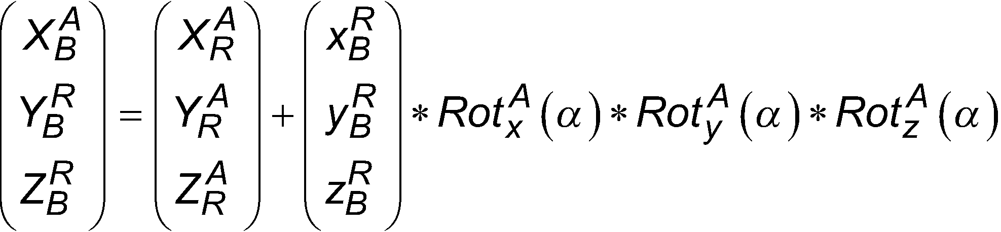
Wie beschrieben, können die Referenzpunkte über eine Transformation von dem Roboterkoordinatensystem in das Anlagenkoordinatensystem transformiert werden. Bei dem Verfahren kann vorgesehen sein, dass die Transformation der Referenzpunkte von dem Roboterkoordinatensystem in das Anlagenkoordinatensystem basierend auf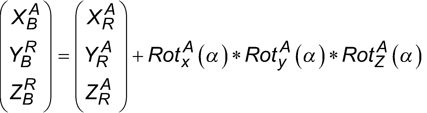
![]()
![]()
![]()
![]()
![]()
![]()
Neben dem Verfahren betrifft die Erfindung eine Vermessungsvorrichtung mit einer Erfassungseinrichtung insbesondere einer optischen Erfassungseinrichtung, welche Vermessungsvorrichtung dazu ausgebildet ist, das zuvor beschriebene Verfahren auszuführen. Die Vermessungsvorrichtung stellt somit insbesondere eine zuvor beschriebene Steuerungsvorrichtung bereit, die dazu eingerichtet ist, die Transformation auszuführen. Die Steuerungsvorrichtung kann hierzu eine geeignete Recheneinrichtung umfassen. Die beschriebene Steuerungsvorrichtung steht in Verbindung mit der Erfassungseinrichtung, die als optische Erfassungseinrichtung, im Speziellen als Tachymeter, ausgebildet sein kann.In addition to the method, the invention relates to a surveying device with a detection device, in particular an optical detection device, which surveying device is designed to carry out the method described above. The surveying device thus provides in particular a control device as described above, which is designed to carry out the transformation. The control device can comprise a suitable computing device for this purpose. The described control device is connected to the detection device, which can be designed as an optical detection device, in particular as a tachymeter.
Sämtliche Vorteile, Einzelheiten, Ausführungen und/oder Merkmale, die in Bezug auf das Verfahren beschrieben wurden, sind vollständig auf die Vermessungsvorrichtung übertragbar.All advantages, details, designs and/or features described with respect to the method are fully transferable to the measuring device.
Die Erfindung ist anhand von Ausführungsbeispielen unter Bezugnahme auf die Fig. erläutert. Die Fig. sind schematische Darstellungen und zeigen:
-
1 eine Prinzipdarstellung einer Vermessungsvorrichtung in einer Werkumgebung gemäß einem Ausführungsbeispiel; und -
2 eine Prinzipdarstellung eines Ablaufdiagramm eines Verfahrens zur Bestimmung einer Absteckposition gemäß einem Ausführungsbeispiel.
-
1 a schematic diagram of a measuring device in a factory environment according to an embodiment; and -
2 a schematic representation of a flow chart of a method for determining a staking position according to an embodiment.
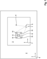
Wie in
Dennoch liegt in dem Anlagenkoordinatensystem 6 für wenige bestimmte Strukturen oder Objekte, beispielsweise den Ursprung bzw. Nullpunkt des Roboters 8, wenigstens eine Position 9 vor, die in dem Anlagenkoordinatensystem 6 referenziert ist, zum Beispiel ein Nullpunkt. Dieser ist, wie strichliert dargestellt, jedoch von dem Roboter 8 verdeckt, sodass dieser mit der Erfassungseinrichtung 5 nicht mehr erfasst werden kann. Ebenso kann es sein, dass es sich bei der Position 9 um eine nicht erfassbare Position handelt, zum Beispiel einen abstrakten Nullpunkt, der keine physische Gestalt aufweist. Soll die Erfassungseinrichtung 5 innerhalb der Roboterzelle 3 referenziert werden, ist dies nur im Roboterkoordinatensystem 7 möglich, da sämtliche Strukturen der Roboterzelle 3 nur in dem Roboterkoordinatensystem 7 referenziert sind und die beispielhaft Position 9, zum Beispiel eine Grundplatte des Roboters 8 oder dessen Nullpunkt, für die Erfassungseinrichtung 5 nicht sichtbar ist.Nevertheless, in the system coordinate
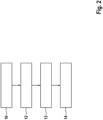
Da die Absteckposition 4 üblicherweise für eine Veränderung der Roboterzelle 3, insbesondere eine Bereitstellung einer neuen Vorrichtung für die Roboterzelle 3 bestimmt werden soll, ist eine Referenzierung in dem Anlagenkoordinatensystem 6 nötig. Um die Absteckposition 4 zu bestimmen kann das hierin beschriebene Verfahren ausgeführt werden. Dies ist als schematisches Ablaufdiagramm in
Die in dem Anlagenkoordinatensystem 6 referenzierten Referenzpunkte 11 können anschließend mit der Erfassungseinrichtung 5 erfasst werden. Beispielsweise können die Referenzpunkte 11 durch Objekte in der Roboterzelle 3 referenziert sein, zum Beispiel die Mittelpunkte von Bohrlöchern und dergleichen, die für die Erfassungseinrichtung 5 sichtbar sind. Grundsätzlich können als Referenzpunkte 11 bzw. Objekte, die Referenzpunkte 11 aufweisen, beliebige Teile der Roboterzelle 3 verwendet werden. Über die Erfassung der Referenzpunkte 11, insbesondere wenigstens drei Referenzpunkte 11, kann die Position der Erfassungseinrichtung 5 innerhalb der Roboterzelle 3 in einem Block 13 bestimmt werden, und zwar im Anlagenkoordinatensystem 6. Anschließend ist in Block 14 möglich, den Absteckpunkt 4 mittels der Erfassungseinrichtung 5 abzustecken, die, wie beschrieben, in dem Anlagenkoordinatensystem 6 referenziert ist.The
Dies erlaubt insbesondere eine freie Stationierung der Erfassungseinrichtung 5 innerhalb der Roboterzelle 3, da diese beliebig positioniert werden kann und anschließend in dem Anlagenkoordinatensystem 6 referenziert werden kann, wie dies zuvor beschrieben wurde. Bei dem Objekt, das die Referenzpunkte 11 aufweist, kann es sich um ein bekanntes Objekt handeln, das entweder manuell festgelegt wird oder aus einem Speicher der Vermessungsvorrichtung 1 bestimmt wird. Hierbei kann es sich beispielsweise um ein Standardbauteil handeln, dessen Objektmerkmale bekannt sind. Um die optische Erfassung der Referenzpunkte 11 weiter zu verbessern kann ein Messobjekt vorgesehen sein, das mit den Referenzpunkten 11 bzw. den sie aufweisenden Objekten gekoppelt werden kann. Zum Beispiel kann ein Prisma direkt oder mittels eines Halters, in Bohrlöcher eingesetzt werden, oder anderweitig mit dem von der Erfassungseinrichtung 5 erfassbaren Objekt innerhalb der Roboterzelle 3 gekoppelt werden. Die Position des Messobjekts kann anschließend über einen Vektor, insbesondere den Prismenvektor, in die Transformation in das Anlagenkoordinatensystem 6 mit einbezogen werden.This allows in particular a free stationing of the
Die in den einzelnen Ausführungsbeispielen gezeigten Vorteile, Einzelheiten und Merkmale sind beliebig miteinander kombinierbar, untereinander austauschbar und aufeinander übertragbar.The advantages, details and features shown in the individual embodiments can be combined with one another as desired, are interchangeable and transferable to one another.
Bezugszeichenlistelist of reference symbols
- 11
- Vermessungsvorrichtungmeasuring device
- 22
- Werkumgebungwork environment
- 33
- Roboterzellerobot cell
- 44
- Absteckpositionstaking position
- 55
- Erfassungseinrichtungrecording device
- 66
- Anlagenkoordinatensystemplant coordinate system
- 77
- Roboterkoordinatensystemrobot coordinate system
- 88
- Roboterrobot
- 99
- Positionposition
- 1010
- Blockblock
- 1111
- Referenzpunktreference point
- 12-1412-14
- Blockblock
Claims (9)
Priority Applications (1)
| Application Number | Priority Date | Filing Date | Title |
|---|---|---|---|
| DE102024100552.1A DE102024100552B3 (en) | 2024-01-10 | 2024-01-10 | Method for determining at least one staking position |
Applications Claiming Priority (1)
| Application Number | Priority Date | Filing Date | Title |
|---|---|---|---|
| DE102024100552.1A DE102024100552B3 (en) | 2024-01-10 | 2024-01-10 | Method for determining at least one staking position |
Publications (1)
| Publication Number | Publication Date |
|---|---|
| DE102024100552B3 true DE102024100552B3 (en) | 2025-02-13 |
Family
ID=94342189
Family Applications (1)
| Application Number | Title | Priority Date | Filing Date |
|---|---|---|---|
| DE102024100552.1A Active DE102024100552B3 (en) | 2024-01-10 | 2024-01-10 | Method for determining at least one staking position |
Country Status (1)
| Country | Link |
|---|---|
| DE (1) | DE102024100552B3 (en) |
Cited By (1)
| Publication number | Priority date | Publication date | Assignee | Title |
|---|---|---|---|---|
| CN119717832A (en) * | 2025-02-27 | 2025-03-28 | 中铁上海工程局集团第七工程有限公司 | Lofting robot navigation method based on total station |
Citations (6)
| Publication number | Priority date | Publication date | Assignee | Title |
|---|---|---|---|---|
| DE10048097A1 (en) | 2000-09-28 | 2002-04-18 | Zeiss Carl | The coordinate |
| DE102011011360A1 (en) | 2011-02-16 | 2012-08-16 | Steinbichler Optotechnik Gmbh | Apparatus and method for determining the 3-D coordinates of an object and for calibrating an industrial robot |
| DE102016213663A1 (en) | 2016-07-26 | 2018-02-01 | Siemens Aktiengesellschaft | Method for controlling an end element of a machine tool and a machine tool |
| DE102019001969B4 (en) | 2018-03-27 | 2022-07-28 | Fanuc Corporation | Robot system for correcting the teaching of a robot by image processing |
| DE112021007324T5 (en) | 2021-05-28 | 2024-04-04 | Fanuc Corporation | TEACHING DEVICE, MARKER MEASUREMENT METHOD AND PROGRAM |
| DE112021007989T5 (en) | 2021-09-30 | 2024-05-29 | Fanuc Corporation | Control unit and robot system |
-
2024
- 2024-01-10 DE DE102024100552.1A patent/DE102024100552B3/en active Active
Patent Citations (6)
| Publication number | Priority date | Publication date | Assignee | Title |
|---|---|---|---|---|
| DE10048097A1 (en) | 2000-09-28 | 2002-04-18 | Zeiss Carl | The coordinate |
| DE102011011360A1 (en) | 2011-02-16 | 2012-08-16 | Steinbichler Optotechnik Gmbh | Apparatus and method for determining the 3-D coordinates of an object and for calibrating an industrial robot |
| DE102016213663A1 (en) | 2016-07-26 | 2018-02-01 | Siemens Aktiengesellschaft | Method for controlling an end element of a machine tool and a machine tool |
| DE102019001969B4 (en) | 2018-03-27 | 2022-07-28 | Fanuc Corporation | Robot system for correcting the teaching of a robot by image processing |
| DE112021007324T5 (en) | 2021-05-28 | 2024-04-04 | Fanuc Corporation | TEACHING DEVICE, MARKER MEASUREMENT METHOD AND PROGRAM |
| DE112021007989T5 (en) | 2021-09-30 | 2024-05-29 | Fanuc Corporation | Control unit and robot system |
Cited By (1)
| Publication number | Priority date | Publication date | Assignee | Title |
|---|---|---|---|---|
| CN119717832A (en) * | 2025-02-27 | 2025-03-28 | 中铁上海工程局集团第七工程有限公司 | Lofting robot navigation method based on total station |
Similar Documents
| Publication | Publication Date | Title |
|---|---|---|
| DE3889819T2 (en) | 3D dimensioning in computer-aided drawing. | |
| DE102013016489B4 (en) | Tool trajectory display device having a function of displaying the reversal position of a servo axis | |
| DE112021003517B4 (en) | numerical control system | |
| DE10065593A1 (en) | Method and device for generating road segment data for a digital map | |
| DE102012202609A1 (en) | ELECTRONIC SYSTEM AND METHOD FOR COMPENSATING THE DIMENSIONAL ACCURACY OF A 4-AXIS CNC MACHINING SYSTEM USING GLOBAL AND LOCAL OFFSETS | |
| DE3725347A1 (en) | COMPUTER-INTEGRATED MEASURING SYSTEM | |
| DE102024100552B3 (en) | Method for determining at least one staking position | |
| DE69202178T2 (en) | Method and system for comparing the equipment on board a vehicle using means for measuring the earth's gravitational and magnetic fields. | |
| DE102020207085A1 (en) | METHOD OF CONTROLLING A ROBOT AND ROBOT CONTROL UNIT | |
| DE102022208089B4 (en) | Device and method for controlling a robot | |
| WO2010034438A1 (en) | Control and/or programming device having a data processing unit for processing a target tool data set of a three-dimensional tool model | |
| DE102019204017A1 (en) | Method and system for calibrating a camera | |
| DE102007011603B4 (en) | Method and device for determining the geometry data of a conical measurement object | |
| DE102022101000A1 (en) | Method of creating a CAM-oriented time spline curve and surface | |
| DE4106168A1 (en) | METHOD FOR METROLOGICAL TESTING AND FOR SELF-CORRECTING GEOMETRIC MEASURING ERRORS IN A MEASURING DEVICE | |
| EP2088486A1 (en) | Method for measuring a non-linear dynamic real system using design of experiment | |
| DE102020203655A1 (en) | Method for providing and transmitting a reduced amount of vehicle data for teleoperated driving | |
| EP4034347B1 (en) | Method for determining a position and/or the orientation of a device top | |
| EP3708945A1 (en) | Evaluation of measurement data from a measuring a plurality of workpieces | |
| DE102015220031A1 (en) | Method for confidence estimation for optical-visual pose determination | |
| DE102017121249A1 (en) | Method and system for machining a workpiece | |
| DE10129654B4 (en) | Method, apparatus and computer program product for determining effects of design changes | |
| DE102008007127A1 (en) | Method for measuring components | |
| DE102020211256A1 (en) | Method and device for determining a component characteristic depending on a manufacturing process using machine learning methods | |
| EP2304621A1 (en) | Parallel navigation in a plurality of cad models |
Legal Events
| Date | Code | Title | Description |
|---|---|---|---|
| R012 | Request for examination validly filed | ||
| R016 | Response to examination communication | ||
| R018 | Grant decision by examination section/examining division | ||
| R020 | Patent grant now final |