DE102022209552B4 - Connection of a sensor arrangement arranged on a mounting plate with a measuring object - Google Patents
Connection of a sensor arrangement arranged on a mounting plate with a measuring object Download PDFInfo
- Publication number
- DE102022209552B4 DE102022209552B4 DE102022209552.9A DE102022209552A DE102022209552B4 DE 102022209552 B4 DE102022209552 B4 DE 102022209552B4 DE 102022209552 A DE102022209552 A DE 102022209552A DE 102022209552 B4 DE102022209552 B4 DE 102022209552B4
- Authority
- DE
- Germany
- Prior art keywords
- mounting plate
- measurement object
- connecting foil
- foil
- solder layer
- Prior art date
- Legal status (The legal status is an assumption and is not a legal conclusion. Google has not performed a legal analysis and makes no representation as to the accuracy of the status listed.)
- Active
Links
Images
Classifications
-
- G—PHYSICS
- G01—MEASURING; TESTING
- G01B—MEASURING LENGTH, THICKNESS OR SIMILAR LINEAR DIMENSIONS; MEASURING ANGLES; MEASURING AREAS; MEASURING IRREGULARITIES OF SURFACES OR CONTOURS
- G01B7/00—Measuring arrangements characterised by the use of electric or magnetic techniques
- G01B7/16—Measuring arrangements characterised by the use of electric or magnetic techniques for measuring the deformation in a solid, e.g. by resistance strain gauge
- G01B7/18—Measuring arrangements characterised by the use of electric or magnetic techniques for measuring the deformation in a solid, e.g. by resistance strain gauge using change in resistance
-
- B—PERFORMING OPERATIONS; TRANSPORTING
- B23—MACHINE TOOLS; METAL-WORKING NOT OTHERWISE PROVIDED FOR
- B23K—SOLDERING OR UNSOLDERING; WELDING; CLADDING OR PLATING BY SOLDERING OR WELDING; CUTTING BY APPLYING HEAT LOCALLY, e.g. FLAME CUTTING; WORKING BY LASER BEAM
- B23K1/00—Soldering, e.g. brazing, or unsoldering
- B23K1/0008—Soldering, e.g. brazing, or unsoldering specially adapted for particular articles or work
- B23K1/0016—Brazing of electronic components
-
- B—PERFORMING OPERATIONS; TRANSPORTING
- B23—MACHINE TOOLS; METAL-WORKING NOT OTHERWISE PROVIDED FOR
- B23K—SOLDERING OR UNSOLDERING; WELDING; CLADDING OR PLATING BY SOLDERING OR WELDING; CUTTING BY APPLYING HEAT LOCALLY, e.g. FLAME CUTTING; WORKING BY LASER BEAM
- B23K26/00—Working by laser beam, e.g. welding, cutting or boring
- B23K26/36—Removing material
- B23K26/38—Removing material by boring or cutting
-
- G—PHYSICS
- G01—MEASURING; TESTING
- G01L—MEASURING FORCE, STRESS, TORQUE, WORK, MECHANICAL POWER, MECHANICAL EFFICIENCY, OR FLUID PRESSURE
- G01L1/00—Measuring force or stress, in general
- G01L1/20—Measuring force or stress, in general by measuring variations in ohmic resistance of solid materials or of electrically-conductive fluids; by making use of electrokinetic cells, i.e. liquid-containing cells wherein an electrical potential is produced or varied upon the application of stress
- G01L1/22—Measuring force or stress, in general by measuring variations in ohmic resistance of solid materials or of electrically-conductive fluids; by making use of electrokinetic cells, i.e. liquid-containing cells wherein an electrical potential is produced or varied upon the application of stress using resistance strain gauges
- G01L1/2206—Special supports with preselected places to mount the resistance strain gauges; Mounting of supports
-
- G—PHYSICS
- G01—MEASURING; TESTING
- G01L—MEASURING FORCE, STRESS, TORQUE, WORK, MECHANICAL POWER, MECHANICAL EFFICIENCY, OR FLUID PRESSURE
- G01L1/00—Measuring force or stress, in general
- G01L1/20—Measuring force or stress, in general by measuring variations in ohmic resistance of solid materials or of electrically-conductive fluids; by making use of electrokinetic cells, i.e. liquid-containing cells wherein an electrical potential is produced or varied upon the application of stress
- G01L1/22—Measuring force or stress, in general by measuring variations in ohmic resistance of solid materials or of electrically-conductive fluids; by making use of electrokinetic cells, i.e. liquid-containing cells wherein an electrical potential is produced or varied upon the application of stress using resistance strain gauges
- G01L1/2287—Measuring force or stress, in general by measuring variations in ohmic resistance of solid materials or of electrically-conductive fluids; by making use of electrokinetic cells, i.e. liquid-containing cells wherein an electrical potential is produced or varied upon the application of stress using resistance strain gauges constructional details of the strain gauges
-
- B—PERFORMING OPERATIONS; TRANSPORTING
- B23—MACHINE TOOLS; METAL-WORKING NOT OTHERWISE PROVIDED FOR
- B23K—SOLDERING OR UNSOLDERING; WELDING; CLADDING OR PLATING BY SOLDERING OR WELDING; CUTTING BY APPLYING HEAT LOCALLY, e.g. FLAME CUTTING; WORKING BY LASER BEAM
- B23K2101/00—Articles made by soldering, welding or cutting
- B23K2101/36—Electric or electronic devices
Landscapes
- Physics & Mathematics (AREA)
- General Physics & Mathematics (AREA)
- Engineering & Computer Science (AREA)
- Mechanical Engineering (AREA)
- Optics & Photonics (AREA)
- Plasma & Fusion (AREA)
- Measurement Of Length, Angles, Or The Like Using Electric Or Magnetic Means (AREA)
Abstract
Verfahren zur Verbindung einer auf einer Montageplatte (17) angeordneten Sensoranordnung (5) mit einem Messobjekt (2), das Verfahren umfassend die Schritte
(100) Bereitstellen
- eines Messobjekts (2),
- einer Sensoranordnung (5), umfassend einen Dehnungsmessstreifen (1), der zumindest dazu eingerichtet ist, dehnende und stauchende Verformungen eines Messobjekts (2) zu erfassen, sowie ein damit verbundenes Elektronikmodul (19), wobei der Dehnungsmessstreifen (1) und das Elektronikmodul (19) jeweils auf der Montageplatte (17) angeklebt sowie in einem Gehäuse (18) eingekapselt sind,
- einer Verbindungsfolie (10), die metallische Materialien (11, 12) enthält, die bei ihrer Aktivierung exotherm reagieren,
(200) Platzieren der Verbindungsfolie (10) zwischen der Montageplatte (17) und dem Messobjekt (2), und
(300) Aktivieren der metallischen Materialien (11, 12) der Verbindungsfolie (10), sodass sich die Verbindungsfolie (10) derart erhitzt, dass zwischen der Montageplatte (17) und dem Messobjekt (2) eine stoffschlüssige Verbindung erzeugt wird.
(100) Provide
- a measuring object (2),
- a sensor arrangement (5) comprising a strain gauge (1) which is at least designed to detect stretching and compressive deformations of a measurement object (2), and an electronic module (19) connected thereto, wherein the strain gauge (1) and the electronic module (19) are each glued to the mounting plate (17) and encapsulated in a housing (18),
- a connecting foil (10) containing metallic materials (11, 12) which react exothermically when activated,
(200) Placing the connecting foil (10) between the mounting plate (17) and the measuring object (2), and
(300) Activating the metallic materials (11, 12) of the connecting foil (10) so that the connecting foil (10) heats up in such a way that a material connection is created between the mounting plate (17) and the measuring object (2).
Description
Die Erfindung betrifft eine Verbindung eines Dehnungsmessstreifens mit einem Messobjekt. Beansprucht werden in diesem Zusammenhang insbesondere ein Verfahren zur Befestigung des Dehnungsmessstreifens an dem Messobjekt sowie eine Anordnung des Dehnungsmessstreifens an dem Messobjekt.The invention relates to a connection of a strain gauge to a measurement object. In this context, it particularly relates to a method for attaching the strain gauge to the measurement object and an arrangement of the strain gauge on the measurement object.
Für verschiedene Anwendungsfälle ist es notwendig, einen Dehnungsmessstreifen an einem größeren mechanischen Bauteil, dem Messobjekt, zu befestigen. Dies ist wichtig für die Platzierung des Sensorsystems und für eine Verschaltung der physikalischen Signale, die gemessen werden sollen. Dehnungsmessstreifen sind Messeinrichtungen zur Erfassung von dehnenden und stauchenden Verformungen. Sie ändern bereits bei geringen Verformungen ihren elektrischen Widerstand und werden als Sensoren zur Dehnungsmessung eingesetzt.For various applications, it is necessary to attach a strain gauge to a larger mechanical component, the measurement object. This is important for the placement of the sensor system and for connecting the physical signals to be measured. Strain gauges are measuring devices for detecting stretching and compressive deformations. They change their electrical resistance even at small deformations and are used as sensors for strain measurement.
Sensoren zur Kraft- oder Verformungsmessung sind stark von der Verbindungs- bzw. Klebeschicht zwischen dem Dehnungsmessstreifen und dem Messobjekt abhängig. Das Messobjekt kann aus verschiedenen Materialien wie Metall, Silizium oder einem organischen Material bestehen. Die Verbindungsschicht muss eine starke Haftung bieten und formstabil sein, um eine gute Kraft- und Deformationsübertragung ohne eine (zusätzliche und unvorhersehbare) Dämpfung oder Zeitverzögerungen zu gewährleisten. Die Sensorleistung über die Lebensdauer hängt von der Langzeitstabilität der Verbindungsschicht ab, insbesondere von der Temperatur-/Feuchtigkeits-/Chemikalienstabilität, um Signaldrift, Signalamplitudenschrumpfung und Zeitverzögerungen zu vermeiden.Sensors for force or deformation measurement are highly dependent on the bonding or adhesive layer between the strain gauge and the measurement object. The measurement object can be made of various materials, such as metal, silicon, or an organic material. The bonding layer must provide strong adhesion and be dimensionally stable to ensure good force and deformation transmission without (additional and unpredictable) damping or time delays. Sensor performance over its lifetime depends on the long-term stability of the bonding layer, particularly its temperature/humidity/chemical stability, to avoid signal drift, signal amplitude shrinkage, and time delays.
Für die Kontaktierung der Dehnungsmessstreifen auf einem größeren Messobjekt ist Kleben bekannt. Die Verbindungsschicht ist also eine Klebeschicht. Dies ist für die industrielle Fertigung relativ einfach zu realisieren, erfordert aber meist einen manuellen Prozess, der zeitaufwendig und nicht kosteneffizient ist. Klebeverbindungen sind mit unterschiedlichen Temperaturgradienten, Feuchtigkeits-/Chemikalienabhängigkeit und Langzeitalterung verbunden. Dies kann die Signalqualität verringern oder den Sensor sogar zerstören. Andere Verbindungstechniken sind aufgrund der Prozessparameter mit hohen Temperaturen, mechanischen Drücken oder hohem Vakuum bzw. Schutzgas unpraktisch. Andere Methoden benötigen starke elektromagnetische Felder. Unpraktisch heißt in diesem Zusammenhang, es könnte den Dehnungsmessstreifen oder das Messobjekt zerstören.Adhesive bonding is a well-known method for bonding strain gauges to a larger measurement object. The bonding layer is therefore an adhesive layer. This is relatively easy to implement for industrial production, but usually requires a manual process that is time-consuming and not cost-effective. Adhesive bonds are associated with varying temperature gradients, humidity/chemical dependence, and long-term aging. This can reduce signal quality or even destroy the sensor. Other bonding techniques are impractical due to process parameters involving high temperatures, mechanical pressures, or high vacuum or inert gas. Other methods require strong electromagnetic fields. In this context, impractical means they could destroy the strain gauge or the measurement object.
Aus der
In der
In der
In der
Die Aufgabe der vorliegenden Erfindung besteht darin, eine neuartige Verbindung zwischen einem Dehnungsmessstreifen und einem Messobjekt vorzuschlagen, welche den vorstehend beschriebenen Problemen Rechnung trägt sowie Dehnungsmessstreifen für Automobilanwendungen einsetzbar macht. Die Aufgabe wird gelöst durch den Gegenstand des unabhängigen Patentanspruchs 1. Vorteilhafte Ausführungsformen sind Gegenstand der Unteransprüche, der folgenden Beschreibung sowie der Figuren.The object of the present invention is to propose a novel connection between a strain gauge and a measurement object that addresses the problems described above and makes strain gauges usable for automotive applications. This object is achieved by the subject matter of
Ein erfindungsgemäßes Verfahren zur Verbindung einer auf einer Montageplatte angeordneten Sensoranordnung mit einem Messobjekt umfasst die Schritte
- (100) Bereitstellen
- - eines Messobjekts,
- - einer Sensoranordnung, umfassend einen Dehnungsmessstreifen, der zumindest dazu eingerichtet ist, dehnende und stauchende Verformungen eines Messobjekts zu erfassen, sowie ein damit verbundenes Elektronikmodul, wobei der Dehnungsmessstreifen und das Elektronikmodul jeweils auf der Montageplatte angeklebt sowie in einem Gehäuse eingekapselt sind,
- - einer Verbindungsfolie, die metallische Materialien enthält, die bei ihrer Aktivierung exotherm reagieren,
- (200) Platzieren der Verbindungsfolie zwischen der Montageplatte und dem Messobjekt, und
- (300) Aktivieren der metallischen Materialien der Verbindungsfolie, sodass sich die Verbindungsfolie derart erhitzt, dass zwischen der Montageplatte und dem Messobjekt eine stoffschlüssige Verbindung erzeugt wird.
- (100) Provide
- - a measuring object,
- - a sensor arrangement comprising a strain gauge which is at least configured to detect stretching and compressive deformations of a measurement object, and an electronic module connected thereto, wherein the strain gauge and the electronic module are each glued to the mounting plate and encapsulated in a housing,
- - a connecting foil containing metallic materials that react exothermically when activated,
- (200) Placing the connecting foil between the mounting plate and the measuring object, and
- (300) Activating the metallic materials of the connecting foil so that the connecting foil heats up in such a way that a material connection is created between the mounting plate and the measuring object.
Die vorliegende Erfindung schlägt einen reaktiven Folienlötprozess vor, um eine insbesondere intermetallische Verbindung für Dehnungsmessstreifen auf einem größeren Messobjekt, auch Target genannt, zu erhalten. Der Fügeprozess basiert auf der Verwendung einer reaktiven Multischichtfolie als lokale Wärmequelle. Die Verbindungsfolie besteht aus einer neuen Klasse von nanotechnologischem Material, in dem sich selbst ausbreitende exotherme Reaktionen bei Raumtemperatur durch einen Zündprozess auslösen lassen. Durch das Einbringen einer solchen Folie zwischen der Montageplatte und dem Messobjekt schmilzt die durch die Reaktion in der Folie erzeugte Wärme beispielsweise Lötschichten oder andere reaktive Schichten auf, sodass die Verbindungen bei Raumtemperatur in etwa einer Sekunde abgeschlossen sind. Die induzierte Wärme während der Reaktion ist aufgrund der schnellen Reaktionsgeschwindigkeit (beispielsweise 10 m/s) und der geringen Materialdicke (beispielsweise <100µm) sehr gering.The present invention proposes a reactive foil soldering process for obtaining a particularly intermetallic bond for strain gauges on a larger measurement object, also called a target. The joining process is based on the use of a reactive multilayer foil as a local heat source. The bonding foil consists of a new class of nanotechnological material in which self-propagating exothermic reactions can be triggered at room temperature by an ignition process. By inserting such a foil between the mounting plate and the measurement object, the heat generated by the reaction in the foil melts, for example, solder layers or other reactive layers, so that the connections are completed in approximately one second at room temperature. The heat induced during the reaction is very low due to the fast reaction rate (e.g., 10 m/s) and the low material thickness (e.g., <100 µm).
In diesem Sinne wird gemäß einem ersten Aspekt der Erfindung ein Verfahren zur Verbindung einer auf einer Montageplatte angeordneten Sensoranordnung mit einem Messobjekt bereitgestellt. In einem ersten Schritt (100) des Verfahrens wird ein Messobjekt bereitgestellt. Weiterhin wird eine Sensoranordnung bereitgestellt, umfassend einen Dehnungsmessstreifen, der zumindest dazu eingerichtet ist, dehnende und stauchende Verformungen eines Messobjekts zu erfassen. Die Erfassung weiterer Messgrößen mit dem Dehnungsmessstreifen ist ebenfalls denkbar. Die Sensoranordnung umfasst ferner ein mit dem Dehnungsmessstreifen verbundenes Elektronikmodul. Das Elektronikmodul umfasst insbesondere eine Vorverstärkerelektronik, das mit dem Dehnungsmessstreifen sowie einer Auswerteeinheit in geeigneter Weise verbunden ist. Der Dehnungsmessstreifen und das Elektronikmodul sind jeweils auf der Montageplatte angeklebt und in einem gemeinsamen Gehäuse eingekapselt. Ferner wird eine Verbindungsfolie bereitgestellt, die metallische Materialien enthält, die bei ihrer Aktivierung exotherm reagieren.In this sense, according to a first aspect of the invention, a method for connecting a sensor arrangement arranged on a mounting plate to a measurement object is provided. In a first step (100) of the method, a measurement object is provided. Furthermore, a sensor arrangement is provided, comprising a strain gauge which is configured at least to detect stretching and compressive deformations of a measurement object. The detection of further measured variables with the strain gauge is also conceivable. The sensor arrangement further comprises an electronics module connected to the strain gauge. The electronics module comprises, in particular, preamplifier electronics which are suitably connected to the strain gauge and an evaluation unit. The strain gauge and the electronics module are each adhesively bonded to the mounting plate and encapsulated in a common housing. Furthermore, a connecting foil is provided which contains metallic materials which react exothermically when activated.
Durch die Kapselung werden der Dehnungsmessstreifen und das Elektronikmodul von der Montageplatte und dem Gehäuse räumlich umgeben. Unter „gekapselt“ oder „eingekapselt“ ist zu verstehen, dass der Dehnungsmessstreifen und das Elektronikmodul im Wesentlichen vollständig von beispielsweise einem Modulgehäuse umgeben sind, insbesondere abdichtend z.B. gegenüber dem Eintritt von Luft und/oder Feuchtigkeit umgeben ist. In einer bevorzugten Ausgestaltungsform sind der Dehnungsmessstreifen und das Elektronikmodul vollständig und nahtlos sowie insbesondere kontaktelementlos - also frei von Kontaktelementen - gekapselt. Lediglich eine Verkabelung kann aus dem Gehäuse zum Anschluss an die Auswerteeinheit herausgeführt sein. In diesem Sinn liegt ein vollständig umgebener Zustand auch dann vor, wenn aus dem Gehäuse eine Verkabelung herausgeführt ist. Beispielsweise sind der Dehnungsmessstreifen und das Elektronikmodul von einer Vergussmasse oder einer Spritzgussmasse vorzugsweise vollständig umgeben. In diesem Fall bildet die Vergussmasse das Modulgehäuse bzw. das Gehäuse der Sensoranordnung. Durch diese Ausgestaltung ist eine mechanische und/oder eine ungewollte elektrische Beeinflussung des Dehnungsmessstreifens und des Elektronikmoduls, beispielsweise durch Feuchtigkeit oder Schmutz, verhindert.Through encapsulation, the strain gauge and the electronic module are spatially surrounded by the mounting plate and the housing. “Encapsulated” or “encapsulated” means that the strain gauge and the electronic module are essentially completely enclosed by, for example, a module housing, in particular sealed, e.g., against the ingress of air and/or moisture. In a preferred embodiment, the strain gauge and the electronic module are completely and seamlessly encapsulated, and in particular without contact elements—i.e., free of contact elements. Only cabling can be led out of the housing for connection to the evaluation unit. In this sense, a completely enclosed state also exists when cabling is led out of the housing. For example, the strain gauge and the electronic module are preferably completely surrounded by a potting compound or an injection-molding compound. In this case, the potting compound forms the module housing or the housing of the sensor arrangement. This embodiment enables mechanical and/or unwanted electrical influences on the strain gauge and the electronic module, for example due to moisture or dirt, are prevented.
Das Messobjekt kann insbesondere deutlich größer sein als die Sensoranordnung. Bei dem Messobjekt kann es sich beispielsweise um ein Target, insbesondere eine Achse, eine Welle für einen Motor, ein Getriebe eines Kraftfahrzeugs, ein Roboterarmsegment für einen Roboter oder ein Kühler, handeln. Die Montageplatte, auf der die Sensoranordnung angeordnet sind, das heißt auf dem der Dehnungsmessstreifen und das Elektronikmodul aufgeklebt sind, ermöglicht eine einfache und unempfindliche Handhabung der Sensoranordnung. Die Montageplatte kann Teil der Sensoranordnung sein. In diesem Fall bilden die Montageplatte, der Dehnungsmessstreifen und das Elektronikmodul ein zusammenhängendes Bauteil, nämlich die Sensoranordnung. Die Sensoranordnung kann separat gelagert, transportiert und verarbeitet werden und erst mit dem erfindungsgemäßen Verfahren stoffschlüssig mit dem Messobjekt verbunden werden. Die Montageplatte ist sodann zwischen dem Messobjekt sowie dem Dehnungsmessstreifen und dem Elektronikmodul angeordnet. Die Montageplatte ermöglicht zudem eine sichere Verbindung der Sensoranordnung mit dem Messobjekt, da eine ungewollte Beschädigung des Dehnungsmessstreifens oder des Elektronikmoduls während der Aktivierung der Verbindungsfolie, insbesondere während des Erhitzens der Materialien der Verbindungsfolie, ausgeschlossen werden kann.The measurement object can, in particular, be significantly larger than the sensor arrangement. The measurement object can be, for example, a target, in particular an axle, a shaft for an engine, a transmission of a motor vehicle, a robot arm segment for a robot, or a radiator. The mounting plate on which the sensor arrangement is arranged, i.e. on which the strain gauge and the electronics module are glued, enables simple and robust handling of the sensor arrangement. The mounting plate can be part of the sensor arrangement. In this case, the mounting plate, the strain gauge, and the electronics module form a coherent component, namely the sensor arrangement. The sensor arrangement can be stored, transported, and processed separately and can only be integrally bonded to the measurement object using the method according to the invention. The mounting plate is then arranged between the measurement object, the strain gauge, and the electronics module. The mounting plate also enables a secure connection of the sensor arrangement to the measuring object, as unintentional damage to the strain gauge or the electronic module during activation of the connecting foil, especially during heating of the materials of the connecting foil, can be excluded.
In diesem Sinn werden der Dehnungsmessstreifen und das Elektronikmodul bevorzugt vor dem Verfahrensschritt (200) von der Montageplatte sowie einer Vergussmasse oder einer Spritzgussmasse vollständig umgeben. Dadurch wird das Gehäuse ausgebildet und die Sensoranordnung ist auch durch spätere Handhabung vor ungewollter Beeinflussung, insbesondere Beschädigung, geschützt. Zudem ist dies vorteilhaft, da die Sensoranordnung unter Reinraumbedingungen herstellbar ist. So können der Dehnungsmessstreifen und das Elektronikmodul auf der Montageplatte aufgeklebt und im Gehäuse eingekapselt werden, ohne dass Verunreinigungen in das Gehäuse gelangen können-In this sense, the strain gauge and the electronic module are preferably completely surrounded by the mounting plate and a potting compound or injection molding compound prior to process step (200). This forms the housing, and the sensor assembly is protected from unwanted influences, particularly damage, even during subsequent handling. This is also advantageous because the sensor assembly can be manufactured under clean-room conditions. This allows the strain gauge and the electronic module to be glued to the mounting plate and encapsulated in the housing without allowing contaminants to enter the housing.
Der Dehnungsmessstreifen ist insbesondere dazu eingerichtet, eine Dehnung, eine Stauchung und/oder ein Drehmoment zu messen, die bzw. das von dem Messobjekt erzeugt wird bzw. davon ausgeht bzw. damit übertragen wird. Der Dehnungsmessstreifen umfasst vorzugsweise eine dem Messobjekt zugewandte Trägerschicht sowie ein Messgitter. Der Dehnungsmessstreifen, kurz DMS, ist vorzugsweise ein Folien-DMS, das heißt, das Messgitter aus Widerstandsdraht, der vorzugsweise 3 bis 5, vorzugsweise bis 8 µm dick ist, wird auf einen dünnen, ein Polymer umfassenden Kunststoffträger kaschiert und ausgeätzt sowie mit elektrischen Anschlüssen versehen, die eine elektronische Verbindung mit dem Elektronikmodul ermöglichen. Zusätzlich kann das Messgitter durch eine Abdeckschicht bedeckt sein, die mit der Trägerschicht verbunden, insbesondere verklebt ist, und die das Messgitter mechanisch schützt. Auch die Abdeckschicht kann auch verzichtet werden, da der Dehnungsmessstreifen im Gehäuse eingekapselt wird. Es können auch mehrere Messgitter auf der Trägerschicht angeordnet sein. Vorteilhafterweise ist die Trägerschicht und/oder die Abdeckschicht in Form einer Folie ausgebildet. Mithin ist die Trägerschicht bevorzugt eine Trägerfolie und/oder die Abdeckschicht eine Abdeckfolie. Die Trägerschicht ist bevorzugt aus Polyimid ausgebildet. Sofern eine Abdeckschicht vorgesehen ist, kann auch dieses aus Polyimid ausgebildet sein.The strain gauge is particularly designed to measure strain, compression, and/or torque generated by, originating from, or transmitted by the measurement object. The strain gauge preferably comprises a carrier layer facing the measurement object and a measuring grid. The strain gauge, or DMS for short, is preferably a foil DMS, i.e., the measuring grid made of resistance wire, which is preferably 3 to 5, preferably up to 8 µm thick, is laminated and etched onto a thin plastic carrier comprising a polymer and provided with electrical connections that enable an electronic connection to the electronic module. In addition, the measuring grid can be covered by a cover layer that is connected to the carrier layer, in particular glued, and which mechanically protects the measuring grid. The cover layer can also be omitted, since the strain gauge is encapsulated in the housing. Multiple measuring grids can also be arranged on the carrier layer. Advantageously, the carrier layer and/or the cover layer are configured in the form of a film. Therefore, the carrier layer is preferably a carrier film and/or the cover layer is preferably a cover film. The carrier layer is preferably made of polyimide. If a cover layer is provided, this can also be made of polyimide.
Als Verbindungsfolie kann beispielsweise eine sogenannte NanoFoil® der Indium Corporation zum Einsatz kommen. Die NanoFoil® ist eine reaktive Multischichtfolie, die durch Aufdampfen von Tausenden von abwechselnden nanoskaligen Schichten beispielsweise aus Aluminium und Nickel hergestellt wird. Denkbar sind auch andere binäre Schichtsysteme, wie Titan und Aluminium, Zirkonium und Silizium oder Paladium und Aluminium. Darüber hinaus sind auch ternäre Systeme zur Ausbildung der Multischichtfolie denkbar. Die Ausbildung der Verbindungsfolie, insbesondere die Auswahl der Materialien, ist im Wesentlichen abhängig von der gewünschten Reaktion beim Aktivieren der Verbindungsfolie, insbesondere der Reaktionstemperatur während der Aktivierung. Wenn die Folie durch einen kleinen Impuls lokaler Energie aus elektrischen, optischen oder thermischen Quellen aktiviert wird, reagiert sie exotherm, um in Bruchteilen einer Sekunde präzise lokale Hitze bis zu Temperaturen von 1500 °C zu erzeugen. Die Dicke der Verbindungsfolie kann an die Anforderungen angepasst werden. Insbesondere kann die Dicke der Verbindungsfolie in Abhängigkeit des Materials des Messobjekts und/oder der Montageplatte und/oder der Trägerschicht des Dehnungsmessstreifens angepasst werden. Je dünner die Verbindungsfolie, desto weniger Energie ist erforderlich, um das Aktivieren der Verbindungsfolie einzuleiten bzw. auszuführen. Die Gesamtenergie ist derart einzustellen, dass eine sichere Verbindung zwischen dem Dehnungsmessstreifen und dem Messobjekt erfolgt.A so-called NanoFoil® from the Indium Corporation can be used as a connecting foil, for example. The NanoFoil® is a reactive multilayer foil produced by vapor deposition of thousands of alternating nanoscale layers, for example, made of aluminum and nickel. Other binary layer systems are also conceivable, such as titanium and aluminum, zirconium and silicon, or palladium and aluminum. Ternary systems for forming the multilayer foil are also conceivable. The design of the connecting foil, in particular the choice of materials, depends essentially on the desired reaction upon activation of the connecting foil, particularly the reaction temperature during activation. When the foil is activated by a small pulse of local energy from electrical, optical, or thermal sources, it reacts exothermically to generate precise local heat up to temperatures of 1500°C in fractions of a second. The thickness of the connecting foil can be adapted to requirements. In particular, the thickness of the connecting foil can be adjusted depending on the material of the measurement object and/or the mounting plate and/or the carrier layer of the strain gauge. The thinner the connecting foil, the less energy is required to initiate or activate the connecting foil. The total energy must be adjusted to ensure a secure connection between the strain gauge and the test object.
Die Verbindungsfolie wird in einem zweiten Verfahrensschritt (200) zwischen der Montageplatte und dem Messobjekt platziert. Das Platzieren kann derart erfolgen, dass die Verbindungsfolie in einer Sandwich-Konfiguration entweder direkt an einander zugewandten Oberflächen der Montageplatte und des Messobjekts anliegt. Alternativ kann das Platzieren derart erfolgen, dass die Verbindungsfolie in einer Sandwich-Konfiguration zwischen zwei Lötschichten angeordnet ist, wobei die Lötschichten auf gegenüberliegenden Oberflächen der Montageplatte und des Messobjekts aufgetragen sind. Ferner alternativ kann das Platzieren derart erfolgen, dass die Verbindungsfolie in einer Sandwich-Konfiguration zwischen zwei Lötschichten angeordnet ist, wobei die Lötschichten auf entgegengesetzten Oberflächen der Verbindungsfolie aufgetragen sind. Diese Oberflächen der Verbindungsfolie sind insbesondere ebene Oberflächen, die im zweiten Verfahrensschritt (200) die Montageplatte bzw. das Messobjekt aufnehmend zwischen der Montageplatte und dem Messobjekt angeordnet werden, um im nachfolgenden dritten Verfahrensschritt (300) verschweißt oder verlötet zu werden.The connecting foil is placed between the mounting plate and the measurement object in a second method step (200). The placement can be carried out in such a way that the connecting foil is placed in a sandwich configuration either directly on the facing surfaces of the mounting plate and of the measurement object. Alternatively, the placement can be carried out such that the connecting foil is arranged in a sandwich configuration between two solder layers, wherein the solder layers are applied to opposite surfaces of the mounting plate and the measurement object. Further alternatively, the placement can be carried out such that the connecting foil is arranged in a sandwich configuration between two solder layers, wherein the solder layers are applied to opposite surfaces of the connecting foil. These surfaces of the connecting foil are in particular flat surfaces which, in the second method step (200), are arranged between the mounting plate and the measurement object, receiving the mounting plate or the measurement object, in order to be welded or soldered in the subsequent third method step (300).
Die Verbindungsfolie bildet im aktivierten Zustand eine Fügefläche zwischen dem Messobjekt und der Montageplatte. Die Verbindungsfolie kann, wenn dies nicht bereits am die Fügefläche bildenden Fügeabschnitt erfolgt, ferner einen Aktivierungsabschnitt aufweisen, an dem die Aktivierung des metallischen Materials der Verbindungsfolie erfolgt. Am Aktivierungsabschnitt können Aktivierungsmittel angeordnet sein, um die Verbindungsfolie aktivieren zu können. Der Fügeabschnitt und ggfs. der Aktivierungsabschnitt sind zwischen der Montageplatte und dem Messobjekt ausgebildet. Die aktivierte Verbindungsfolie verbindet das Messobjekt mit der Montageplatte zumindest in der Fügefläche, vorzugsweise in der Fügefläche sowie ggfs. im Aktivierungsabschnitt stoffschlüssig. Sofern ein Aktivierungsabschnitt vorgesehen ist, liegt dieser damit außerhalb der Fügefläche zwischen der Montageplatte und dem Messobjekt.When activated, the connecting foil forms a joining surface between the measurement object and the mounting plate. If this does not already occur at the joining section forming the joining surface, the connecting foil can also have an activation section where the metallic material of the connecting foil is activated. Activation means can be arranged at the activation section to activate the connecting foil. The joining section and, if applicable, the activation section are formed between the mounting plate and the measurement object. The activated connecting foil connects the measurement object to the mounting plate in a material-to-material bond at least in the joining surface, preferably in the joining surface and, if applicable, in the activation section. If an activation section is provided, it is therefore located outside the joining surface between the mounting plate and the measurement object.
Mit der Verbindungsfolie, insbesondere mit dem Aktivierungsabschnitt, sofern ein solcher vorgesehen ist, ist wenigstens ein, vorzugsweise mehrere Aktivierungsmittel elektrisch verbunden. Das Aktivierungsmittel kann einen oder mehrere Drähte aufweisen, vorzugsweise zwei Drähte, einer mit positivem Pol, also einem Pluspol, und einer mit negativem Pol, also einem Minuspol, wobei zwischen den Polen eine Potentialdifferenz vorliegt. Die Drähte können separat ausgebildet sein und hantiert werden. Alternativ können die beiden Drähte an ihren Enden zu einer Art Stecker zusammengefasst sein, um einen definierten Abstand der Drähte beizubehalten bzw. nicht zu unterschreiten. Das Aktivierungsmittel kann ferner eine Spannungsquelle, insbesondere eine Batterie, oder eine Wärmenadel sein oder umfassen. Alternativ kann das Aktivierungsmittel dazu ausgebildet sein, zur Aktivierung der Verbindungsfolie mit der Spannungsquelle verbunden zu werden. Das Aktivierungsmittel und/oder die Spannungsquellen kann bzw. können mit dem Elektronikmodul verbunden sein.At least one, preferably several, activation means are electrically connected to the connecting foil, in particular to the activation section, if one is provided. The activation means can have one or more wires, preferably two wires, one with a positive pole, i.e. a plus pole, and one with a negative pole, i.e. a minus pole, with a potential difference between the poles. The wires can be formed and handled separately. Alternatively, the two wires can be combined at their ends to form a type of plug in order to maintain or not undercut a defined distance between the wires. The activation means can also be or comprise a voltage source, in particular a battery, or a heat needle. Alternatively, the activation means can be designed to be connected to the voltage source for activating the connecting foil. The activation means and/or the voltage sources can be connected to the electronic module.
In einem dritten Verfahrensschritt (300) erfolgt ein Aktivieren der metallischen Materialien der Verbindungsfolie über das jeweilige Aktivierungsmittel, sodass sich die Verbindungsfolie derart erhitzt, dass die Montageplatte mit dem Messobjekt stoffschlüssig verbunden wird. Zwischen der Montageplatte und dem Messobjekt liegt nach dem Aktivieren der Verbindungsfolie eine stoffschlüssige Verbindung vor. Das Aktivieren kann beispielsweise durch eine Zündung erfolgen. Das Verfahren benötigt keine besondere Hitze, kein Vakuum und keine Gasatmosphäre. Die Zündung der Verbindungsfolie kann beispielsweise mit einer handelsüblichen 9V-Batterie erfolgen, wobei die Batterie über das jeweilige Aktivierungsmittel zumindest mittelbar mit der Verbindungsfolie verbunden ist. In dem Verfahrensschritt (300) kann das Material des Messobjekts und/oder der Montageplatte aufgeschmolzen oder angeschmolzen werden, sodass die Montageplatte direkt mit dem Messobjekt verschweißt wird. Alternativ kann die Montageplatte durch Aufschmelzen von Lötschichten am Messobjekt und/oder an der Montageplatte und/oder an der Verbindungsfolie indirekt mit dem Messobjekt verlötet werden.In a third method step (300), the metallic materials of the connecting foil are activated via the respective activation agent, so that the connecting foil heats up to such an extent that the mounting plate is bonded to the measurement object. After activation of the connecting foil, a bond is formed between the mounting plate and the measurement object. Activation can occur, for example, through ignition. The method requires no particular heat, no vacuum, and no gas atmosphere. The connecting foil can be ignited, for example, using a commercially available 9V battery, with the battery being at least indirectly connected to the connecting foil via the respective activation agent. In method step (300), the material of the measurement object and/or the mounting plate can be melted or partially melted, so that the mounting plate is welded directly to the measurement object. Alternatively, the mounting plate can be indirectly soldered to the measurement object by melting solder layers on the measurement object and/or on the mounting plate and/or on the connecting foil.
Während des Bonding-Verfahrens müssen keine hohen Drücke und keine hohen Temperaturen auf die Sensoranordnung und/oder die Montageplatte und/oder das Messobjekt ausgeübt werden. Auch auf hohe elektromagnetische Felder kann verzichtet werden. Die durch das Aktivieren der metallischen Materialien der Verbindungsfolie entstehende durchgängige, metallische Verbindungsschicht oder Bondfläche zwischen der Montageplatte und dem Messobjekt weist aufgrund der verbesserten Kontaktierung insbesondere eine hohe Formstabilität sowie eine hohe Wärmeleitfähigkeit und elektrische Leitfähigkeit auf. Weiterhin vereinfacht sich der Herstellungsprozess bzw. der Bondprozess, was eine besonders kostengünstige Produktion ermöglicht.During the bonding process, no high pressures or high temperatures need to be applied to the sensor array and/or the mounting plate and/or the measurement object. Strong electromagnetic fields are also eliminated. The continuous, metallic bonding layer or bonding surface between the mounting plate and the measurement object, created by activating the metallic materials of the bonding foil, exhibits particularly high dimensional stability as well as high thermal and electrical conductivity due to the improved contact. Furthermore, the manufacturing process and the bonding process are simplified, enabling particularly cost-effective production.
Das erfindungsgemäße Verfahren zeichnet sich durch geringere Temperaturen und Spannungen während des Verbindens aus. Diese geringeren Spannungen induzieren weniger Vorspannungen im Dehnungsmessstreifen und der Montageplatte und erhöhen die Leistung und die Stabilität des Dehnungsmessstreifens. Darüber hinaus ermöglichen die niedrigen Temperaturen und der niedrige Druck einen breiten Einsatz von Materialien, wie beispielsweise Polymere. Der durch das erfindungsgemäße Verfahren erzeugte Verbund zwischen Montageplatte und Messobjekt altert nicht mit der Zeit und Temperaturen. Dampf, Druck oder ähnliches bewirken keine Veränderung von Parametern der Verbindung. Das Verbundmaterial (Metall) ist insbesondere beständig gegen Feuchtigkeit, Chemikalien, hohe/niedrige Temperaturen und schnelle Temperaturwechsel. Der Verbund verändert deshalb seine Parameter nicht, insbesondere durch Temperatur, Feuchtigkeit, Druck oder Ähnliches. Das Verbundmaterial (insbesondere Metall) bietet weiterhin eine elastische Verformung für Wiederholbarkeit.The inventive method is characterized by lower temperatures and stresses during bonding. These lower stresses induce less prestress in the strain gauge and the mounting plate, increasing the performance and stability of the strain gauge. Furthermore, the low temperatures and low pressure enable a broad application of materials, such as polymers. The bond between the mounting plate and the measurement object created by the inventive method does not age with time and temperatures. Steam, pressure, or similar factors do not cause any change in the bond parameters. The composite material (metal) is particularly resistant to moisture, chemicals, high Low temperatures and rapid temperature changes. The composite therefore does not change its parameters, especially due to temperature, humidity, pressure, or similar. The composite material (especially metal) continues to offer elastic deformation for repeatability.
Vorteilhafterweise kann die elektrische Verbindung zwischen dem Aktivierungsmittel und der Verbindungsfolie mit der gleichen Vorrichtung erfolgen, mit der die Montageplatte auf dem Messobjekt platziert und der Druck zur stoffschlüssigen Verbindung ausgeübt wird.Advantageously, the electrical connection between the activating agent and the connecting foil can be made with the same device with which the mounting plate is placed on the measuring object and the pressure is exerted for the material connection.
Die Verbindungsfolie wird durch Laserschneiden derart bearbeitet, dass die Verbindungsfolie eine Form und Maße annimmt, die eine vorgesehene Fügefläche zwischen der Montageplatte und dem Messobjekt abdeckt. Die Verbindungsfolie kann damit besonders genau und effizient in den gewünschten Abmessungen geformt werden, bevor die Verbindungsfolie zwischen den beiden Oberflächen platziert wird. The connecting foil is laser-cut to a shape and dimensions that perfectly fit the intended joining surface between the mounting plate and the measurement object. This allows the connecting foil to be formed to the desired dimensions with exceptional precision and efficiency before being placed between the two surfaces.
Mithin erfolgt das Laserschneiden bevor die Verbindungsfolie in dem Schritt (200) zwischen der Montageplatte und dem Messobjekt platziert wird.Therefore, the laser cutting takes place before the connecting foil is placed between the mounting plate and the measuring object in step (200).
Das Verbindungsverfahren gemäß der vorliegenden Erfindung eignet sich aufgrund der Eliminierung oder Reduzierung von Druckspannungen besonders für Sensoranordnungen mit Dehnungsmessstreifen. Die Montage des DMS an das Messobjekt kann dadurch vereinfacht und beschleunigt werden sowie mit reproduzierbarer Qualität erfolgen. Insbesondere kann die Montage der Montageplatte mit der daran angeordneten Sensoranordnung am Messobjekt zumindest teilautomatisiert, vorzugsweise vollautomatisiert werden.The connection method according to the present invention is particularly suitable for sensor arrangements with strain gauges due to the elimination or reduction of compressive stresses. The mounting of the strain gauge to the measurement object can thus be simplified and accelerated, and can be carried out with reproducible quality. In particular, the mounting of the mounting plate with the sensor arrangement arranged thereon to the measurement object can be at least partially automated, preferably fully automated.
Nach einer bevorzugten Ausführungsform wird eine oder mehrere Lötschichten auf der Verbindungsfolie und/oder der Montageplatte und/oder dem Messobjekt aufgetragen. Vorzugsweise weist die Montageplatte und/oder die Verbindungsfolie eine metallisierte erste Lötschicht auf, die im Schritt (200) zwischen der Montageplatte und der Verbindungsfolie angeordnet ist. Die erste Lötschicht ist als erste Beschichtung der Montageplatte und/oder der Verbindungsfolie zu verstehen, die in mehrere Einzelschichten unterteilt sein kann.According to a preferred embodiment, one or more solder layers are applied to the connecting foil and/or the mounting plate and/or the measurement object. Preferably, the mounting plate and/or the connecting foil has a metallized first solder layer, which is arranged between the mounting plate and the connecting foil in step (200). The first solder layer is to be understood as the first coating of the mounting plate and/or the connecting foil, which can be divided into several individual layers.
Bevorzugt weist die Verbindungsfolie und/oder das Messobjekt ein metallisierte zweite Lötschicht auf, die im Schritt (200) zwischen dem Messobjekt und der Verbindungsfolie angeordnet ist. Die zweite Lötschicht ist als zweite Beschichtung des Messobjekts und/oder der Verbindungsfolie zu verstehen, die ebenfalls in mehrere Einzelschichten unterteilt sein kann. Die jeweilige Lötschicht ist eine metallisierte Schicht, die eine wirksame stoffschlüssige Verbindung zwischen dem Dehnungsmessstreifen und dem Messobjekt ermöglicht.Preferably, the connecting foil and/or the measurement object has a metallized second solder layer, which is arranged between the measurement object and the connecting foil in step (200). The second solder layer is to be understood as a second coating of the measurement object and/or the connecting foil, which can also be divided into several individual layers. The respective solder layer is a metallized layer that enables an effective, material-to-material connection between the strain gauge and the measurement object.
Die jeweilige Lötschicht wird insbesondere aufgetragen, bevor die Verbindungsfolie in dem zweiten Verfahrensschritt (200) zwischen der Montageplatte und dem Messobjekt platziert wird. Durch anschließendes Aktivieren der Verbindungsfolie entsteht ausreichend Wärme, um die jeweilige Lötschicht aufzuschmelzen und die Montageplatte mit dem Messobjekt zu verlöten. In diesem Sinne ist gemäß einer Ausführungsform vorgesehen, dass
- - die erste Lötschicht auf der Montageplatte und/oder der Verbindungsfolie aufgetragen wird,
- - die zweite Lötschicht auf dem Messobjekt und/oder der Verbindungsfolie aufgetragen wird,
- - die Verbindungsfolie mit den Lötschichten in dem Schritt (200) zwischen der Montageplatte und dem Messobjekt platziert wird, und
- - die metallischen Materialien der Verbindungsfolie in dem Schritt (300) aktiviert werden, sodass sich die Verbindungsfolie derart erhitzt, dass die erste Lötschicht und die zweite Lötschicht schmelzen und die Montageplatte durch die aufgeschmolzene erste Lötschicht und die aufgeschmolzene zweite Lötschicht mit dem Messobjekt verlötet wird, um die stoffschlüssige Verbindung zu erzeugen. Die Metallisierung des Messobjekts, der Montageplatte und/oder der Verbindungsfolie, also das Aufbringen der Lötschicht auf das Messobjekt, die Montageplatte und/oder die Verbindungsfolie ist wichtig, um den Nanobond-Prozess zu ermöglichen.
- - the first solder layer is applied to the mounting plate and/or the connecting foil,
- - the second solder layer is applied to the measuring object and/or the connecting foil,
- - the connecting foil with the solder layers is placed between the mounting plate and the measuring object in step (200), and
- - the metallic materials of the connecting foil are activated in step (300) so that the connecting foil heats up such that the first solder layer and the second solder layer melt, and the mounting plate is soldered to the measurement object by the melted first solder layer and the melted second solder layer to create the integral connection. The metallization of the measurement object, the mounting plate, and/or the connecting foil, i.e., the application of the solder layer to the measurement object, the mounting plate, and/or the connecting foil, is important to enable the nanobond process.
Mittels der Verbindungsfolie und der Lötschichten kann zwischen der Montageplatte und dem Messobjekt eine intermetallische, stoffschlüssige Bindung geschaffen werden, die keine hohen Temperaturen, Drücke, elektromagnetische Felder, etc. zur Herstellung benötigt. Durch die intermetallische Verbindung wird eine 1:1-Signalübertragung vom Messobjekt zum Dehnungsmessstreifen ermöglicht.Using the bonding foil and solder layers, an intermetallic, material-tight bond can be created between the mounting plate and the measurement object, which does not require high temperatures, pressures, electromagnetic fields, etc. to create. The intermetallic bond enables a 1:1 signal transmission from the measurement object to the strain gauge.
Die Lötschichten können als metallische Startschichten (erste und zweite Lötschicht) besonders vorteilhaft durch Plasmaverfahren, Sputterverfahren oder Aufdampfen auf der jeweiligen Oberfläche der zu verbindenden Teile (Montageplatte, Messobjekt, Verbindungsfolie) aufgebracht werden. Weitere Möglichkeiten sind durch Zwei-Schuss-Spritzgießen, additive Fertigung usw. gegeben. Wenigstens eine der Lötschichten, vorzugsweise beide Lötschichten, umfassen bevorzugt Nickel. Ferner bevorzugt umfasst eine der Lötschichten, vorzugsweise beiden Lötschichten, Gold. Auch Kupfer oder Palladium eignen sich als Material für die jeweilige Lötschicht. Das Material der jeweiligen Lötschicht ist an die Abmessungen sowie den Werkstoff der Verbindungsfolie, der Montageplatte und/oder des Messobjekts angepasst.The solder layers can be applied as metallic starting layers (first and second solder layers) particularly advantageously by plasma processes, sputtering processes, or vapor deposition on the respective surface of the parts to be joined (mounting plate, measurement object, connecting foil). Further possibilities include two-shot injection molding, additive manufacturing, etc. At least one of the solder layers, preferably both solder layers, preferably comprise nickel. Preferably, one of the solder layers, preferably both solder layers, comprises gold. Copper or palladium are also suitable materials for the respective solder layer. The material of the respective solder layer is adapted to the dimensions and the material of the connecting foil, the mounting plate, and/or the measurement object.
Nach einem Ausführungsbeispiel umfasst die jeweilige Lötschicht eine Nickelschicht sowie eine Goldschicht. Mit anderen Worten ist die jeweilige Beschichtung mehrschichtig ausgebildet. Der Schichtaufbau kann beliebig ausgestaltet sein. Vorzugsweise ist die Goldschicht der Verbindungsfolie zugewandt. Bevorzugt ist Nickelschicht dem Messobjekt und/oder der Montageplatte zugewandt und somit der Verbindungsfolie abgewandt.According to one embodiment, the respective solder layer comprises a nickel layer and a gold layer. In other words, the respective coating is multi-layered. The layer structure can be configured as desired. Preferably, the gold layer faces the connecting foil. Preferably, the nickel layer faces the measurement object and/or the mounting plate and thus faces away from the connecting foil.
Um eine unvorhersehbare Verformung des Verbundes zu verhindern, kann ein Fixierpad mit geringem Druck auf die Schichten gelegt werden. In diesem Sinne wird bevorzugt mittels eines Fixierpads, das zumindest mittelbar auf die Sensoranordnung und/oder die Montageplatte und/oder das Messobjekt einen Druck ausübt, einer Verformung der Lötschichten und der Verbindungsfolie während des Aktivierens und Verbindens in Schritt (300) entgegengewirkt. Der Druck ist dabei derart gering, dass er zu keinen Spannungen innerhalb der Montageplatte und/oder des Dehnungsmessstreifens und/oder des Messobjekts führt, welche die Festigkeit der Verbindung zwischen der Montageplatte und dem Messobjekt oder die Messgenauigkeit beinträchtigen könnten.To prevent unforeseeable deformation of the composite, a fixing pad can be applied to the layers with low pressure. In this sense, deformation of the solder layers and the connecting foil during activation and connection in step (300) is preferably counteracted by means of a fixing pad that exerts pressure at least indirectly on the sensor arrangement and/or the mounting plate and/or the measurement object. The pressure is so low that it does not lead to any stresses within the mounting plate and/or the strain gauge and/or the measurement object that could impair the strength of the connection between the mounting plate and the measurement object or the measurement accuracy.
„Zumindest mittelbar“ heißt in diesem Zusammenhang, dass zwischen dem Fixierpad und der Montageplatte und/oder der Sensoranordnung und/oder dem Messobjekt weitere, insbesondere plattenförmige Bauteile, wie beispielsweise eine Wärmesenke, angeordnet sein können. Das Fixierpad kann auch direkt auf der Montageplatte und/oder der Sensoranordnung und/oder dem Messobjekt angeordnet sein.In this context, "at least indirectly" means that additional, particularly plate-shaped components, such as a heat sink, can be arranged between the fixing pad and the mounting plate and/or the sensor arrangement and/or the measurement object. The fixing pad can also be arranged directly on the mounting plate and/or the sensor arrangement and/or the measurement object.
Gemäß einem zweiten Aspekt der Erfindung wird eine Anordnung einer auf einer Montageplatte angeordneten Sensoranordnung an einem Messobjekt bereitgestellt, wobei die Sensoranordnung durch ein Verfahren gemäß dem ersten Aspekt der Erfindung mit dem Messobjekt verbunden worden ist.According to a second aspect of the invention, an arrangement of a sensor arrangement arranged on a mounting plate on a measurement object is provided, wherein the sensor arrangement has been connected to the measurement object by a method according to the first aspect of the invention.
Die obigen Definitionen sowie Ausführungen zu technischen Effekten, Vorteilen und vorteilhaften Ausführungsformen des erfindungsgemäßen Verfahrens gelten sinngemäß ebenfalls für die erfindungsgemäße Anordnung gemäß dem zweiten Erfindungsaspekt. Es versteht sich, dass die vorstehend genannten und die nachstehend noch zu erläuternden Merkmale nicht nur in der jeweils angegebenen Kombination, sondern auch in anderen Kombinationen oder in Alleinstellung verwendbar sind, ohne den Rahmen der vorliegenden Erfindung zu verlassen.The above definitions as well as explanations of technical effects, advantages, and advantageous embodiments of the method according to the invention also apply mutatis mutandis to the inventive arrangement according to the second aspect of the invention. It is understood that the features mentioned above and those to be explained below can be used not only in the respective combinations specified, but also in other combinations or on their own, without departing from the scope of the present invention.
Im Folgenden wird ein Ausführungsbeispiel der Erfindung anhand der schematischen Zeichnungen näher erläutert, wobei gleiche oder ähnliche Elemente mit dem gleichen Bezugszeichen versehen sind. Hierbei zeigt
-
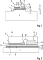
1 eine Längsschnittdarstellung einer erfindungsgemäßen Anordnung einer auf einer Montageplatte angeordneten Sensoranordnung an einem Messobjekt gemäß einer ersten Ausführungsform, wobei die Montageplatte mittels einer - hier stark vereinfacht dargestellten - Verbindungsfolie an dem Messobjekt befestigt ist, -
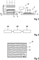
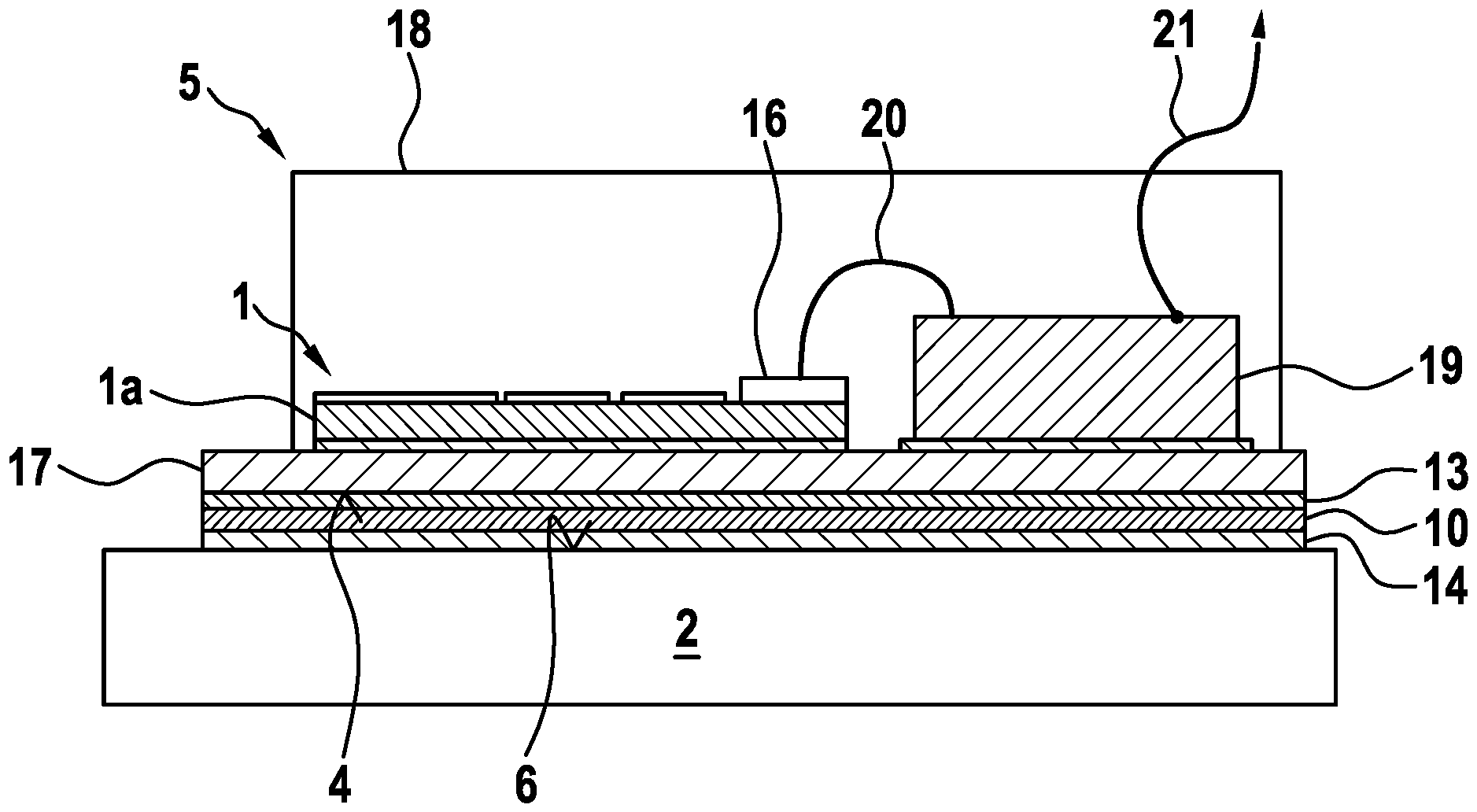
2 eine detaillierte Längsschnittdarstellung der erfindungsgemäßen Anordnung gemäß1 , -
3 eine Explosionsdarstellung von Schichten und Werkzeugen zur Verbindung der Sensoranordnung mit dem Messobjekt mittels der Verbindungsfolie sowie die durch das Verbinden entstehende Anordnung nach der zweiten Ausführungsform, -
4 einen Ablauf eines erfindungsgemäßen Verfahrens zur Verbindung der Sensoranordnung mitdem Messobjekt nach 1 bis3 , und -
5 eine stark vergrößerte Querschnittsansicht der Verbindungsfolie für dieAnordnung nach 1 bis 4 .
-
1 a longitudinal sectional view of an arrangement according to the invention of a sensor arrangement arranged on a mounting plate on a measuring object according to a first embodiment, wherein the mounting plate is attached to the measuring object by means of a connecting foil - shown here in a highly simplified manner, -
2 a detailed longitudinal sectional view of the arrangement according to the invention according to1 , -
3 an exploded view of layers and tools for connecting the sensor arrangement to the measuring object by means of the connecting foil and the arrangement resulting from the connection according to the second embodiment, -
4 a sequence of a method according to the invention for connecting the sensor arrangement to the measurement object according to1 until3 , and -
5 a greatly enlarged cross-sectional view of the connecting foil for the arrangement according to1 until4 .
Mittels der Verbindungsfolie 10 wird eine feste, hier eine stoffschlüssige Verbindung der Montageplatte 17 mit dem Messobjekt 2 realisiert. Diese Verbindung überträgt Kräfte der Messgröße sowie auch Störgrößen durch thermische Ausdehnung. Die Art der Verbindung stellt dabei Anforderungen an die Oberflächenbeschaffenheit von Messobjekt 2 und Montageplatte 17. Zwei rechts außen in
In einem ersten Verfahrensschritt 100 werden das Messobjekt 2, die Sensoranordnung 5, umfassend den Dehnungsmessstreifen 1 und das Elektronikmodul 19, die Montageplatte 17 und die Verbindungsfolie 10 bereitgestellt. Die Verbindungsfolie 10 ist in allen Ausführungsbeispielen eine sogenannte NanoFoil®, also eine reaktive Multischichtfolie, die durch Aufdampfen von Tausenden von abwechselnden nanoskaligen Schichten aus Aluminium 11 und Nickel 12 hergestellt wird. Eine stark vergrößerte Querschnittsansicht der Verbindungsfolie 10 mit den Aluminium- 11 und Nickelschichten 12 ist in
In einem zweiten Verfahrensschritt 200 wird die Verbindungsfolie 10 zwischen der Montageplatte 17 und dem Messobjekt 2 platziert, wie dies durch
Die Verbindungsfolie 10 ist durch Laserschneiden derart bearbeitet, dass die Verbindungsfolie 10 die eine Form und Maße annimmt, die eine vorgesehene Fügefläche 7 zwischen der Montageplatte 17 und dem Messobjekt 2 bildet. Eine Batterie 15 ist als Aktivierungsmittel 16 vorgesehen, das elektrisch mit der Verbindungsfolie 10 verbunden ist.The connecting
In einem dritten Verfahrensschritt 300 werden die Aluminiumschichten 11 und die Nickelschichten 12 der Verbindungsfolie 10 nach
Mithin wird eine stoffschlüssige Verbindung zwischen der Montageplatte 17 und dem Messobjekt 2 realisiert. Die Montageplatten-Oberfläche 4 und/oder Messobjekt-Oberfläche 6 kann eine derartige Oberflächenstruktur aufweisen, dass aufgeschmolzenes Material der Aluminiumschichten 11 und/oder der Nickelschichten 12 in Zwischenräume der Messobjekt-Oberfläche 6 und/oder der Montageplatten-Oberfläche 4 eindringen und nach der Erstarrung einen Formschluss zwischen der Montageplatte 17 und dem Messobjekt 2 bewirken kann. Die detektierbare Messgröße kann durch besondere Strukturen Kraftnebenschluss des Messobjekts 2 erhöht werden. Das Messobjekt 2 kann beispielsweise Vertiefungen, Rippen, Sicken oder ähnliches bilden, die Kräfte in bestimmten Raumrichtungen verstärken oder verringern.Thus, a material-to-material connection is realized between the mounting
In einer weiteren in
Ein Fixierpad 9, das eine nachgiebige Schicht 22 umfasst, übt einen Druck p auf den durch den Dehnungsmessstreifen 1, das Messobjekt 2 sowie durch die beiden Lötschichten 13, 14 gebildeten Stapel aus. Dieser Druck ist sehr gering und wirkt senkrecht auf eine äußere Oberfläche der Sensoranordnung 5. Der Druck dient dazu, einer Verformung der Lötschichten 13, 14 und der Verbindungsfolie 10 während des Aktivierens und Verbindens in Schritt 300 entgegenzuwirken.A
Es sei ausdrücklich darauf hingewiesen, dass die Erfindung nicht auf die hier offenbarten Ausführungsbeispiele beschränkt ist. Es handelt sich lediglich um beispielhafte Ausgestaltungen, wobei auch weitere Varianten möglich sind. Insbesondere kann auf die zweite Lötschicht 14 am Messobjekt 2 verzichtet werden, wenn das Messobjekt 2 aus einem lötbaren Material besteht oder eine bereits metallisierte Oberfläche aufweist.It should be expressly noted that the invention is not limited to the embodiments disclosed here. These are merely exemplary embodiments, although other variants are also possible. In particular, the
BezugszeichenReference symbol
- FF
- KraftPower
- pp
- DruckPressure
- 11
- Dehnungsmessstreifenstrain gauges
- 1a1a
- TrägerschichtCarrier layer
- 1b1b
- Messgittermeasuring grid
- 22
- MessobjektMeasurement object
- 44
- Montageplatten-OberflächeMounting plate surface
- 55
- SensoranordnungSensor arrangement
- 66
- Messobjekt-OberflächeMeasuring object surface
- 77
- FügeflächeJoining surface
- 88
- AktivierungsabschnittActivation section
- 99
- FixierpadFixing pad
- 1010
- VerbindungsfolieConnecting foil
- 1111
- Aluminiumschichtaluminum layer
- 1212
- NickelschichtNickel layer
- 1313
- Erste LötschichtFirst solder layer
- 1414
- Zweite LötschichtSecond solder layer
- 1515
- Batteriebattery
- 1616
- AktivierungsmittelActivating agent
- 1717
- MontageplatteMounting plate
- 1818
- GehäuseHousing
- 1919
- ElektronikmodulElectronic module
- 2020
- Erste VerkabelungFirst cabling
- 2121
- Zweite VerkabelungSecond cabling
- 2222
- Nachgiebige SchichtFlexible layer
- 100100
- Erster VerfahrensschrittFirst procedural step
- 200200
- Zweiter VerfahrensschrittSecond procedural step
- 300300
- Dritter VerfahrensschrittThird procedural step
Claims (11)
Priority Applications (2)
| Application Number | Priority Date | Filing Date | Title |
|---|---|---|---|
| DE102022209552.9A DE102022209552B4 (en) | 2022-09-13 | 2022-09-13 | Connection of a sensor arrangement arranged on a mounting plate with a measuring object |
| PCT/EP2023/074837 WO2024056571A1 (en) | 2022-09-13 | 2023-09-11 | Connection of a sensor assembly, arranged on a mounting plate, to a measurement object |
Applications Claiming Priority (1)
| Application Number | Priority Date | Filing Date | Title |
|---|---|---|---|
| DE102022209552.9A DE102022209552B4 (en) | 2022-09-13 | 2022-09-13 | Connection of a sensor arrangement arranged on a mounting plate with a measuring object |
Publications (2)
| Publication Number | Publication Date |
|---|---|
| DE102022209552A1 DE102022209552A1 (en) | 2024-03-14 |
| DE102022209552B4 true DE102022209552B4 (en) | 2025-03-27 |
Family
ID=88017659
Family Applications (1)
| Application Number | Title | Priority Date | Filing Date |
|---|---|---|---|
| DE102022209552.9A Active DE102022209552B4 (en) | 2022-09-13 | 2022-09-13 | Connection of a sensor arrangement arranged on a mounting plate with a measuring object |
Country Status (2)
| Country | Link |
|---|---|
| DE (1) | DE102022209552B4 (en) |
| WO (1) | WO2024056571A1 (en) |
Citations (4)
| Publication number | Priority date | Publication date | Assignee | Title |
|---|---|---|---|---|
| DE102013002144A1 (en) | 2013-01-30 | 2014-07-31 | Institut für innovative Technologien, Technologietransfer, Ausbildung und berufsbegleitende Weiterbildung (ITW) e. V. | Method for joining thermally sensitive structures between electronic components, involves applying thermal load within outline portions of to be joined contacts formed on solder interconnection layers of solder layer system |
| WO2016199286A1 (en) | 2015-06-12 | 2016-12-15 | 株式会社日立製作所 | Strain detection system and attachment method |
| EP2796830B1 (en) | 2011-12-06 | 2019-03-13 | Hitachi, Ltd. | Strain measuring device |
| EP3839460A1 (en) | 2019-12-19 | 2021-06-23 | General Electric Company | Sensor system and method |
Family Cites Families (3)
| Publication number | Priority date | Publication date | Assignee | Title |
|---|---|---|---|---|
| WO2015121415A1 (en) * | 2014-02-14 | 2015-08-20 | Continental Teves Ag & Co. Ohg | Method for manufacturing a sensor, and sensor |
| US11604105B2 (en) * | 2018-12-05 | 2023-03-14 | 4Iiii Innovations Inc. | Adhesive strain sensing pods with improved protection |
| EP4354082A3 (en) * | 2019-11-18 | 2024-06-12 | Philip Schmitt | Micromechanical device for the self-powered measurement and storage of a mechanical displacement signal |
-
2022
- 2022-09-13 DE DE102022209552.9A patent/DE102022209552B4/en active Active
-
2023
- 2023-09-11 WO PCT/EP2023/074837 patent/WO2024056571A1/en not_active Ceased
Patent Citations (4)
| Publication number | Priority date | Publication date | Assignee | Title |
|---|---|---|---|---|
| EP2796830B1 (en) | 2011-12-06 | 2019-03-13 | Hitachi, Ltd. | Strain measuring device |
| DE102013002144A1 (en) | 2013-01-30 | 2014-07-31 | Institut für innovative Technologien, Technologietransfer, Ausbildung und berufsbegleitende Weiterbildung (ITW) e. V. | Method for joining thermally sensitive structures between electronic components, involves applying thermal load within outline portions of to be joined contacts formed on solder interconnection layers of solder layer system |
| WO2016199286A1 (en) | 2015-06-12 | 2016-12-15 | 株式会社日立製作所 | Strain detection system and attachment method |
| EP3839460A1 (en) | 2019-12-19 | 2021-06-23 | General Electric Company | Sensor system and method |
Also Published As
| Publication number | Publication date |
|---|---|
| DE102022209552A1 (en) | 2024-03-14 |
| WO2024056571A1 (en) | 2024-03-21 |
Similar Documents
| Publication | Publication Date | Title |
|---|---|---|
| EP1842407B1 (en) | Control module | |
| DE102022209553B4 (en) | Connection of a sensor arrangement arranged on a mounting plate with a measuring object | |
| EP0189492B1 (en) | Method for manufacturing a measuring transducer for measuring mechanical quantities | |
| WO2023016920A1 (en) | Connection of a sensor chip to a measurement object | |
| WO2012007428A1 (en) | Cell connector | |
| WO2024033037A1 (en) | Connecting a strain gauge to a measurement object | |
| DE102022120673A1 (en) | Sensor element for detecting at least one physical or chemical measurement variable and sensor arrangement | |
| WO2023152097A1 (en) | Connection of a sensor chip to a measurement object | |
| DE102022205507B3 (en) | Connection of a sensor chip to a measurement object | |
| WO2024056574A1 (en) | Connection of a sensor assembly to a measurement object | |
| DE102022209552B4 (en) | Connection of a sensor arrangement arranged on a mounting plate with a measuring object | |
| DE102022209550B4 (en) | Connection of a sensor arrangement arranged on a mounting plate with a measuring object | |
| DE102007026827A1 (en) | Single-axis force-torque-sensor for robot-supported manipulation and assembling processes, has extension measuring structure for detecting deformation, realized as part of metal lamination of printed circuit board in deformable area | |
| EP2883024A2 (en) | Sensor having simple connection technology | |
| DE102024206899A1 (en) | Connection of a sensor device to a measured object | |
| EP3256820B1 (en) | Transmission control module | |
| DE19826426C2 (en) | Miniaturized electronic system and method for its manufacture | |
| DE102024201700B4 (en) | Methods for the material-bonded joining of components | |
| DE102021208776A1 (en) | Arrangement of a sensor chip on a measurement object | |
| DE102019122623A1 (en) | Sensor component, semi-finished product, method for attaching and manufacturing a sensor component | |
| EP1598650A1 (en) | Method of producing a sensor or actuator and sensor or actuator produceable therewith | |
| DE10055943A1 (en) | Device for measuring mechanical load using a deformation sensor that is able to operate at high temperatures and is based on a metallic measurement body with ceramic and electrical resistance layers on its surface | |
| DE102024201321B3 (en) | Device and method for producing a component | |
| DE602004004210T2 (en) | Electrical connector for connecting electrical units, electrical assembly and method of manufacture | |
| DE102008013412B3 (en) | Manufacturing process for radiation detector module for detecting X-ray or gamma radiation, by contacting electrically conductive contact elements on a part of first and/or second contact areas of corresponding first and second components |
Legal Events
| Date | Code | Title | Description |
|---|---|---|---|
| R012 | Request for examination validly filed | ||
| R016 | Response to examination communication | ||
| R018 | Grant decision by examination section/examining division | ||
| R020 | Patent grant now final |