DE102022100552B3 - SELF LUBRICATION STRAP - Google Patents
SELF LUBRICATION STRAP Download PDFInfo
- Publication number
- DE102022100552B3 DE102022100552B3 DE102022100552.6A DE102022100552A DE102022100552B3 DE 102022100552 B3 DE102022100552 B3 DE 102022100552B3 DE 102022100552 A DE102022100552 A DE 102022100552A DE 102022100552 B3 DE102022100552 B3 DE 102022100552B3
- Authority
- DE
- Germany
- Prior art keywords
- strap
- self
- lubricating
- ratchet
- frame
- Prior art date
- Legal status (The legal status is an assumption and is not a legal conclusion. Google has not performed a legal analysis and makes no representation as to the accuracy of the status listed.)
- Active
Links
Images

Classifications
-
- B—PERFORMING OPERATIONS; TRANSPORTING
- B25—HAND TOOLS; PORTABLE POWER-DRIVEN TOOLS; MANIPULATORS
- B25B—TOOLS OR BENCH DEVICES NOT OTHERWISE PROVIDED FOR, FOR FASTENING, CONNECTING, DISENGAGING, OR HOLDING
- B25B25/00—Implements for fastening, connecting or tensioning of wire or strip
Landscapes
- Engineering & Computer Science (AREA)
- Mechanical Engineering (AREA)
- General Details Of Gearings (AREA)
Abstract
Ein selbstschmierender Spanngurt umfasst einen Rahmen mit zwei Wänden, einer Rolle, zwei Ratschenrädern, zwei Arretierungen, einen kurzen Gurt und einen langen Gurt. Der Rahmen besteht aus zwei Wänden, die jeweils mit einer Buchse versehen sind. Der Griff umfasst zwei Flügel, die jeweils mit einer Öffnung versehen sind. Die Rolle umfasst zwei Endstücke, die in die Buchsen eingesetzt sind. Die beiden Ratschenräder sind mit der Rolle verbunden. Die erste Arretierung ist auf dem Rahmen beweglich und kann mit den Ratschenrädern in Eingriff gebracht werden. Die zweite Arretierung ist am Griff beweglich und kann mit den Ratschenrädern in Eingriff gebracht werden. Der kurze Gurt hat ein Ende, das mit dem Rahmen verbunden ist. Der lange Gurt hat ein Ende, das mit der Rolle verbunden ist, so dass die Rolle zum Aufwickeln des langen Gurtes verwendet werden kann. Jede der Buchsen umfasst mindestens eine Ausnehmung und ein in die Ausnehmung eingefülltes Schmiermittel.A self-lubricating ratchet strap includes a frame with two walls, a pulley, two ratchet wheels, two detents, a short strap, and a long strap. The frame consists of two walls, each with a socket. The handle comprises two wings, each provided with an opening. The reel includes two end pieces inserted into the bushings. The two ratchet wheels are connected to the reel. The first detent is movable on the frame and is engageable with the ratchet wheels. The second detent is moveable on the handle and can be engaged with the ratchet wheels. The short strap has one end connected to the frame. The long strap has one end connected to the reel so the reel can be used to wind up the long strap. Each of the bushings includes at least one recess and a lubricant filled in the recess.
Description
HINTERGRUND DER ERFINDUNGBACKGROUND OF THE INVENTION
1. GEBIET DER ERFINDUNG1. FIELD OF THE INVENTION
Die vorliegende Erfindung bezieht sich auf einen Spanngurt und insbesondere auf einen selbstschmierenden Spanngurt.The present invention relates to a tie-down strap and more particularly to a self-lubricating tie-down strap.
2. BESCHREIBUNG DES STANDES DER TECHNIK2. DESCRIPTION OF THE PRIOR ART
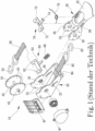
Bezugnehmend auf
Der Gurt 80 hat ein Ende, das mit einem Haken 82 verbunden ist und ein anderes Ende, das mit einer Querstange 84 verbunden ist. Die Querstange 84 hat zwei Enden, die jeweils mit den Wänden 24 verbunden sind.The
Der Griff 30 umfasst einen Griff 32, der zwischen zwei Flügeln 34 gebildet wird. Jeder der Flügel 34 des Griffs 30 weist eine Öffnung 36 und einen Schlitz 38 auf.The
Die Rolle 40 hat die Form einer Achse oder Welle mit zwei Endabschnitten 42. Die Endabschnitte 42 sind in die Buchse 26 eingesetzt und werden von dieser gehalten.The
Jedes der Ratschenräder 50 ist mit Ratschen 52 versehen. Die Ratschenräder 50 sind mit der Rolle 40 verbunden, so dass die Endabschnitte 42 der Rolle 40 über die Ratschenräder 50 hinausragen.Each of the
Die Arretierung 60 umfasst zwei Rippen 62 und einen Vorsprung 64. Die Rippen 62 sind beweglich in die Schlitze 28 der Wände 24 des Rahmens 20 eingesetzt. Jede der Rippen 62 wird verwendet, um mit den Ratschen 52 eines der entsprechenden Ratschenräder 50 in Eingriff zu kommen.The detent 60 includes two
Eine Feder 66 ist auf dem Vorsprung 64 gelagert. Die Feder 66 wird zwischen der Arretierung 60 und einer von der Basis 22 des Rahmens 20 abgehobenen Lasche (nicht nummeriert) zusammengedrückt, um die Rippen 62 in Eingriff mit den Ratschen 52 zu halten.A
Der Gurt 90 hat ein Ende, das mit einem Haken 92 verbunden ist, und ein anderes Ende, das mit der Rolle 40 verbunden ist. Der Gurt 90 kann auf die Rolle 40 aufgewickelt werden.The
Die Arretierung 70 besteht aus zwei Rippen 72 und einem Vorsprung 74. Die Rippen 72 sind beweglich in die Schlitze 38 der Flügel 34 des Griffs 30 eingesetzt. Jede der Rippen 72 wird verwendet, um mit den Ratschen 52 eines der entsprechenden Ratschenräder 50 in Eingriff zu kommen.The detent 70 consists of two
Eine Feder 76 ist auf dem Vorsprung 74 gelagert. Die Feder 76 ist eine Drehmomentfeder, die zwischen der Arretierung 70 und einem geeigneten Teil des Griffs 30 vorgesehen ist, um die Rippen 72 in Eingriff mit den Ratschen 52 zu halten.A
Wie oben erwähnt, werden die Endabschnitte 42 der Rolle 40 in die Buchse 26 eingesetzt und von dieser gehalten. Es wird erwartet, dass sich die Endabschnitte 42 der Rolle 40 reibungslos auf der Buchse 26 drehen, um ein reibungsloses Auf- und Abwickeln des Gurtes 90 zu ermöglichen. Die Endabschnitte 42 der Rolle 40 können jedoch durch die Buchsen 26 eingeklemmt werden, wenn zwischen ihnen Rost auftritt, nachdem der Spanngurt 10 einige Zeit lang verwendet wurde. In diesem Fall, ist die Auf- und Abwicklung des Gurtes 90 nicht reibungslos, was nicht wünschenswert ist.As mentioned above, the
In Dokument
Die vorliegende Erfindung zielt daher darauf ab, die im Stand der Technik aufgetretenen Probleme zu beseitigen oder zumindest zu mildern.The present invention therefore aims to eliminate or at least alleviate the problems encountered in the prior art.
KURZFASSUNG DER ERFINDUNGSUMMARY OF THE INVENTION
Das Hauptziel der vorliegenden Erfindung ist es, einen selbstschmierenden Spanngurt bereitzustellen.The main objective of the present invention is to provide a self-lubricating ratchet strap.
Um das vorgenannte Ziel zu erreichen, umfasst der selbstschmierende Spanngurt einen Rahmen mit zwei Wänden, von denen jede mit einer Buchse versehen ist, einen Griff mit zwei Flügeln, von denen jeder mit einer Öffnung versehen ist, eine Rolle mit zwei Endabschnitten, die in die Buchsen eingesetzt sind, zwei mit der Rolle verbundene Ratschenräder, eine erste Arretierung, die auf dem Rahmen beweglich ist und mit den Ratschenrädern in Eingriff gebracht werden kann, eine zweite Arretierung, die auf dem Griff beweglich ist und mit den Ratschenrädern in Eingriff gebracht werden kann, ein kurzer Gurt mit einem Ende, das mit dem Rahmen verbunden ist, und ein langer Gurt mit einem Ende, das mit der Rolle verbunden ist, so dass die Rolle zur Aufwicklung des langen Gurtes verwendet werden kann. Jede der Buchsen enthält mindestens eine Ausnehmung und ein in die Ausnehmung eingefülltes Schmiermittel.In order to achieve the above objective, the self-lubricating ratchet strap comprises a frame with two walls, each of which is provided with a bush, a handle with two wings, each of which is provided with an opening, a pulley with two end portions inserted into the bushings are used, two ratchet wheels connected to the reel, a first detent movable on the frame and engageable with the ratchet wheels, a second detent movable on the handle and engageable with the ratchet wheels , a short strap with one end connected to the frame and a long strap with one end connected to the reel so the reel can be used to wind up the long strap. Each of the bushings includes at least one recess and a lubricant filled in the recess.
Weitere Ziele, Vorteile und Merkmale der vorliegenden Erfindung ergeben sich aus der folgenden Beschreibung unter Bezugnahme auf die beigefügten Zeichnungen.Other objects, advantages and features of the present invention will become apparent from the following description with reference to the accompanying drawings.
Figurenlistecharacter list
Die vorliegende Erfindung wird anhand einer detaillierten Darstellung von fünf Ausführungsformen unter Bezugnahme auf die Zeichnungen beschrieben, wobei:
-
1 ist eine Explosionsansicht eines typischen Spanngurtes; -
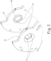
2 ist eine Teil- und Perspektivansicht eines Rahmens eines selbstschmierenden Spanngurtes gemäß der ersten Ausführungsform der vorliegenden Erfindung; -
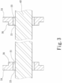
3 ist eine Teil- und Querschnittsansicht einer Rolle zusätzlich zu dem in2 dargestellten Rahmen; -
4 ist eine Teil- und Schnittansicht eines Rahmens eines selbstschmierenden Spanngurts gemäß der zweiten Ausführungsform der vorliegenden Erfindung; -
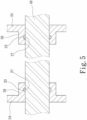
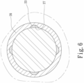
5 ist eine Teil- und Querschnittsansicht eines Rahmens eines selbstschmierenden Spanngurts gemäß der dritten Ausführungsform der vorliegenden Erfindung; -
6 ist eine weitere Teil- und Querschnittsansicht des in5 gezeigten selbstschmierenden Spanngurts; -
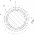
7 ist eine Teil- und Querschnittsansicht eines Rahmens eines selbstschmierenden Spanngurts gemäß der vierten Ausführungsform der vorliegenden Erfindung; -
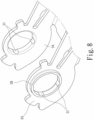
8 ist eine Teil- und Perspektivansicht eines Rahmens eines selbstschmierenden Spanngurts gemäß der fünften Ausführungsform der vorliegenden Erfindung; und -
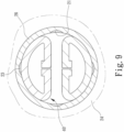
9 ist eine Teil- und Querschnittsansicht einer Rolle zusätzlich zu dem in8 dargestellten Rahmen.
-
1 Figure 12 is an exploded view of a typical ratchet strap; -
2 12 is a partial and perspective view of a frame of a self-lubricating ratchet strap according to the first embodiment of the present invention; -
3 Fig. 12 is a partial and cross-sectional view of a roller in addition to that in Fig2 frame shown; -
4 Fig. 13 is a partial and sectional view of a frame of a self-lubricating ratchet strap according to the second embodiment of the present invention; -
5 Fig. 12 is a partial and cross-sectional view of a frame of a self-lubricating ratchet strap according to the third embodiment of the present invention; -
6 is another partial and cross-sectional view of the in5 shown self-lubricating strap; -
7 12 is a partial and cross-sectional view of a frame of a self-lubricating ratchet strap according to the fourth embodiment of the present invention; -
8th 12 is a partial and perspective view of a frame of a self-lubricating ratchet strap according to the fifth embodiment of the present invention; and -
9 Fig. 12 is a partial and cross-sectional view of a roller in addition to that in Fig8th frame shown.
DETAILLIERTE BESCHREIBUNG DER BEVORZUGTEN AUSFÜHRUNGSFORMDETAILED DESCRIPTION OF THE PREFERRED EMBODIMENT
Gemäß einer ersten Ausführungsform der vorliegenden Erfindung umfasst ein selbstschmierender Spanngurt einen Spanngurt 10 unter Bezugnahme auf
Bezugnehmend auf
Bezugnehmend auf
Bezugnehmend auf
Bezugnehmend auf
Bezugnehmend auf
Bezugnehmend auf
In einer anderen Ausführungsform der vorliegenden Erfindung werden mehrere bogenförmige Nuten anstelle der einzelnen Ringnut 29 verwendet. Das heißt, die einzelne Ringnut 29 ist in mehrere bogenförmige Nuten unterteilt.In another embodiment of the present invention, a plurality of arcuate grooves are used in place of the single
Die Längsnuten 21 und 25, die Bohrungen 27 und die Ringnut 29 sind Ausnehmungen. Ausnehmungen in anderen Formen können in den Buchsen 26 des Rahmens 20 des selbstschmierenden Spanngurts verwendet werden.The
Die vorliegende Erfindung ist anhand der detaillierten Darstellung der Ausführungsformen beschrieben worden. Der Fachmann kann Variationen von den Ausführungsbeispielen ableiten, ohne vom Anwendungsbereich der vorliegenden Erfindung abzuweichen. Daher schränken die Ausführungsbeispiele den in den Ansprüchen definierten Umfang der vorliegenden Erfindung nicht ein.The present invention has been described by showing the embodiments in detail. Those skilled in the art can derive variations from the exemplary embodiments without departing from the scope of the present invention. Therefore, the embodiments do not limit the scope of the present invention as defined in the claims.
Claims (10)
Priority Applications (1)
| Application Number | Priority Date | Filing Date | Title |
|---|---|---|---|
| DE102022100552.6A DE102022100552B3 (en) | 2022-01-11 | 2022-01-11 | SELF LUBRICATION STRAP |
Applications Claiming Priority (1)
| Application Number | Priority Date | Filing Date | Title |
|---|---|---|---|
| DE102022100552.6A DE102022100552B3 (en) | 2022-01-11 | 2022-01-11 | SELF LUBRICATION STRAP |
Publications (1)
| Publication Number | Publication Date |
|---|---|
| DE102022100552B3 true DE102022100552B3 (en) | 2023-05-11 |
Family
ID=86053477
Family Applications (1)
| Application Number | Title | Priority Date | Filing Date |
|---|---|---|---|
| DE102022100552.6A Active DE102022100552B3 (en) | 2022-01-11 | 2022-01-11 | SELF LUBRICATION STRAP |
Country Status (1)
| Country | Link |
|---|---|
| DE (1) | DE102022100552B3 (en) |
Citations (6)
| Publication number | Priority date | Publication date | Assignee | Title |
|---|---|---|---|---|
| US20030131451A1 (en) | 2002-01-11 | 2003-07-17 | Brown Raymond S. | Dual action locking buckle device |
| WO2004067318A1 (en) | 2003-01-27 | 2004-08-12 | Groupe 2T2 Inc. | Winch, vehicle including the same and method of operating associated thereto |
| US20050278902A1 (en) | 2004-06-22 | 2005-12-22 | Michael Wilcox | Strap-tensioning device with tension indicator |
| EP1876374A1 (en) | 2005-04-25 | 2008-01-09 | Ashimori Industry Co., Ltd. | Belt fastening device |
| WO2014017926A1 (en) | 2012-07-23 | 2014-01-30 | Hte Holdings Limited | Chain tensioning device |
| WO2018073098A1 (en) | 2016-10-20 | 2018-04-26 | Westdeutscher Drahtseil-Verkauf Dolezych Gmbh & Co. Kg | Tensioning device for ropes and chains, comprising a lead screw and ratchet unit |
-
2022
- 2022-01-11 DE DE102022100552.6A patent/DE102022100552B3/en active Active
Patent Citations (6)
| Publication number | Priority date | Publication date | Assignee | Title |
|---|---|---|---|---|
| US20030131451A1 (en) | 2002-01-11 | 2003-07-17 | Brown Raymond S. | Dual action locking buckle device |
| WO2004067318A1 (en) | 2003-01-27 | 2004-08-12 | Groupe 2T2 Inc. | Winch, vehicle including the same and method of operating associated thereto |
| US20050278902A1 (en) | 2004-06-22 | 2005-12-22 | Michael Wilcox | Strap-tensioning device with tension indicator |
| EP1876374A1 (en) | 2005-04-25 | 2008-01-09 | Ashimori Industry Co., Ltd. | Belt fastening device |
| WO2014017926A1 (en) | 2012-07-23 | 2014-01-30 | Hte Holdings Limited | Chain tensioning device |
| WO2018073098A1 (en) | 2016-10-20 | 2018-04-26 | Westdeutscher Drahtseil-Verkauf Dolezych Gmbh & Co. Kg | Tensioning device for ropes and chains, comprising a lead screw and ratchet unit |
Similar Documents
| Publication | Publication Date | Title |
|---|---|---|
| EP1296850B1 (en) | Tension ratchet with a belt magazine, and belt magazine | |
| EP0145643A2 (en) | Device for fixing belts to connectors, tensioning and/or checking devices | |
| DE3040164A1 (en) | DEVICE FOR ATTACHING A LOAD TO A PLATFORM | |
| DE20113047U1 (en) | Load securing system | |
| EP0984873B1 (en) | Load indicator on traction elements | |
| DE102022100552B3 (en) | SELF LUBRICATION STRAP | |
| EP0145646A2 (en) | Device for fixing belts to members, tensioning and/or checking devices | |
| DE102016112823B4 (en) | Belt tensioner for containers beam-shaped body | |
| AT522586A4 (en) | Vehicle body with a device for securing loads | |
| DE202024104545U1 (en) | Load securing device for cable drums | |
| DE202016102046U1 (en) | Lashing strap for securing cargo | |
| DE202016100102U1 (en) | Slack Line jig | |
| DE20211100U1 (en) | Link chain with coded chain links | |
| DE29911346U1 (en) | Hook for attaching a transport belt or the like. | |
| DE2150308C3 (en) | Drive device for ropes | |
| DE102025108421A1 (en) | Device for clamping objects | |
| DE10050000A1 (en) | Ratchet with belt magazine | |
| EP3374036B1 (en) | Securing system for securing persons on containers | |
| DE102024001899A1 (en) | tensioning strap | |
| DE557838C (en) | Spill | |
| DE202024100290U1 (en) | A tensioner with damping | |
| DE202023105734U1 (en) | Device for attachment to a textile chain | |
| DE102024137281A1 (en) | Device for lifting loads | |
| DE102025003452A1 (en) | Clamping device | |
| DE10329795B4 (en) | Device for looping in and fixing straps or the like lashing members |
Legal Events
| Date | Code | Title | Description |
|---|---|---|---|
| R012 | Request for examination validly filed | ||
| R016 | Response to examination communication | ||
| R018 | Grant decision by examination section/examining division | ||
| R020 | Patent grant now final |