DE102021130552B4 - towing system with trailer tracking control - Google Patents

towing system with trailer tracking control Download PDF

Info

Publication number
DE102021130552B4
DE102021130552B4 DE102021130552.7A DE102021130552A DE102021130552B4 DE 102021130552 B4 DE102021130552 B4 DE 102021130552B4 DE 102021130552 A DE102021130552 A DE 102021130552A DE 102021130552 B4 DE102021130552 B4 DE 102021130552B4
Authority
DE
Germany
Prior art keywords
trailer
target
hitch
point
towing vehicle
Prior art date
Legal status (The legal status is an assumption and is not a legal conclusion. Google has not performed a legal analysis and makes no representation as to the accuracy of the status listed.)
Active
Application number
DE102021130552.7A
Other languages
German (de)
Other versions
DE102021130552A1 (en
Inventor
Avesta Goodarzi
Norman J. Weigert
Current Assignee (The listed assignees may be inaccurate. Google has not performed a legal analysis and makes no representation or warranty as to the accuracy of the list.)
GM Global Technology Operations LLC
Original Assignee
GM Global Technology Operations LLC
Priority date (The priority date is an assumption and is not a legal conclusion. Google has not performed a legal analysis and makes no representation as to the accuracy of the date listed.)
Filing date
Publication date
Application filed by GM Global Technology Operations LLC filed Critical GM Global Technology Operations LLC
Publication of DE102021130552A1 publication Critical patent/DE102021130552A1/en
Application granted granted Critical
Publication of DE102021130552B4 publication Critical patent/DE102021130552B4/en
Active legal-status Critical Current
Anticipated expiration legal-status Critical

Links

Images

Classifications

    • BPERFORMING OPERATIONS; TRANSPORTING
    • B62LAND VEHICLES FOR TRAVELLING OTHERWISE THAN ON RAILS
    • B62DMOTOR VEHICLES; TRAILERS
    • B62D13/00Steering specially adapted for trailers
    • BPERFORMING OPERATIONS; TRANSPORTING
    • B62LAND VEHICLES FOR TRAVELLING OTHERWISE THAN ON RAILS
    • B62DMOTOR VEHICLES; TRAILERS
    • B62D11/00Steering non-deflectable wheels; Steering endless tracks or the like
    • B62D11/02Steering non-deflectable wheels; Steering endless tracks or the like by differentially driving ground-engaging elements on opposite vehicle sides
    • B62D11/06Steering non-deflectable wheels; Steering endless tracks or the like by differentially driving ground-engaging elements on opposite vehicle sides by means of a single main power source
    • B62D11/10Steering non-deflectable wheels; Steering endless tracks or the like by differentially driving ground-engaging elements on opposite vehicle sides by means of a single main power source using gearings with differential power outputs on opposite sides, e.g. twin-differential or epicyclic gears
    • BPERFORMING OPERATIONS; TRANSPORTING
    • B60VEHICLES IN GENERAL
    • B60DVEHICLE CONNECTIONS
    • B60D1/00Traction couplings; Hitches; Draw-gear; Towing devices
    • B60D1/24Traction couplings; Hitches; Draw-gear; Towing devices characterised by arrangements for particular functions
    • BPERFORMING OPERATIONS; TRANSPORTING
    • B60VEHICLES IN GENERAL
    • B60DVEHICLE CONNECTIONS
    • B60D1/00Traction couplings; Hitches; Draw-gear; Towing devices
    • B60D1/24Traction couplings; Hitches; Draw-gear; Towing devices characterised by arrangements for particular functions
    • B60D1/246Traction couplings; Hitches; Draw-gear; Towing devices characterised by arrangements for particular functions for actuating the hitch by powered means
    • BPERFORMING OPERATIONS; TRANSPORTING
    • B60VEHICLES IN GENERAL
    • B60DVEHICLE CONNECTIONS
    • B60D1/00Traction couplings; Hitches; Draw-gear; Towing devices
    • B60D1/24Traction couplings; Hitches; Draw-gear; Towing devices characterised by arrangements for particular functions
    • B60D1/30Traction couplings; Hitches; Draw-gear; Towing devices characterised by arrangements for particular functions for sway control, e.g. stabilising or anti-fishtail devices; Sway alarm means
    • BPERFORMING OPERATIONS; TRANSPORTING
    • B60VEHICLES IN GENERAL
    • B60DVEHICLE CONNECTIONS
    • B60D1/00Traction couplings; Hitches; Draw-gear; Towing devices
    • B60D1/58Auxiliary devices
    • BPERFORMING OPERATIONS; TRANSPORTING
    • B62LAND VEHICLES FOR TRAVELLING OTHERWISE THAN ON RAILS
    • B62DMOTOR VEHICLES; TRAILERS
    • B62D13/00Steering specially adapted for trailers
    • B62D13/005Steering specially adapted for trailers operated from tractor steering system
    • BPERFORMING OPERATIONS; TRANSPORTING
    • B62LAND VEHICLES FOR TRAVELLING OTHERWISE THAN ON RAILS
    • B62DMOTOR VEHICLES; TRAILERS
    • B62D53/00Tractor-trailer combinations; Road trains
    • B62D53/005Combinations with at least three axles and comprising two or more articulated parts
    • BPERFORMING OPERATIONS; TRANSPORTING
    • B62LAND VEHICLES FOR TRAVELLING OTHERWISE THAN ON RAILS
    • B62DMOTOR VEHICLES; TRAILERS
    • B62D11/00Steering non-deflectable wheels; Steering endless tracks or the like
    • BPERFORMING OPERATIONS; TRANSPORTING
    • B62LAND VEHICLES FOR TRAVELLING OTHERWISE THAN ON RAILS
    • B62DMOTOR VEHICLES; TRAILERS
    • B62D13/00Steering specially adapted for trailers
    • B62D13/04Steering specially adapted for trailers for individually-pivoted wheels
    • BPERFORMING OPERATIONS; TRANSPORTING
    • B62LAND VEHICLES FOR TRAVELLING OTHERWISE THAN ON RAILS
    • B62DMOTOR VEHICLES; TRAILERS
    • B62D59/00Trailers with driven ground wheels or the like

Landscapes

  • Engineering & Computer Science (AREA)
  • Transportation (AREA)
  • Mechanical Engineering (AREA)
  • Chemical & Material Sciences (AREA)
  • Combustion & Propulsion (AREA)
  • Steering Control In Accordance With Driving Conditions (AREA)

Abstract

Zugsystem, das umfasst:ein Zugfahrzeug (101);einen ersten Anhänger (103);einen zweiten Anhänger (102) zwischen dem Zugfahrzeug (101) und dem ersten Anhänger (103), wobei der zweite Anhänger (102) wenigstens eine Achse (120) und wenigstens zwei Räder (109) und ein Lenkungssystem (115) umfasst, wobei der zweite Anhänger (102) bei einem ersten Anhängerkupplungspunkt (H1) unter einem Anhängerkupplungs-Knickwinkel (θ1) mit dem Zugfahrzeug (101) gelenkig gekuppelt ist und bei einem zweiten Anhängerkupplungspunkt (H2) mit dem ersten Anhänger (103) gelenkig gekuppelt ist; undeinen Controller (159), der den Anhängerkupplungs-Knickwinkel (θ1) durch Steuern der Lenkung der wenigstens zwei Räder (109) des zweiten Anhängers (102) auf einen Ziel-Anhängerkupplungs-Knickwinkel (θ1-target) festsetzt; dadurch gekennzeichnet, dassder Ziel-Anhängerkupplungs-Knickwinkel (θ1-target) in Übereinstimmung mit den folgenden Beziehungen bestimmt wird:θ1−target=sin−1λtanδvd2(tanδv)2+L12−tan−1eL2−c−cos−1L1d2(tanδv)2+L12;λ=(α+L1)2−(L32+d2)+2bL1tanδV+b22L3;undL3=(L2−c)2+e2;wobei:θ1-targetder Ziel-Anhängerkupplungs-Knickwinkel (θ1-target) ist;L1ein Radstand des Zugfahrzeugs (101) ist;L2eine Länge des zweiten Anhängers (102) zwischen dem ersten Anhängerkupplungspunkt (H1) und dem zweiten Anhängerkupplungspunkt (H2) ist;L3ein Abstand zwischen dem ersten Anhängerkupplungspunkt (H1) und einem vorgegebenen Punkt an dem zweiten Anhänger (102) ist;δVder Lenkwinkel des Zugfahrzeugs (101) ist;a ein Längsabstand von einem Vorderachsenmittelpunkt an dem Zugfahrzeug (101) zu einem vorgegebenen Punkt an dem Zugfahrzeug (101) ist;b ein seitlicher Abstand von dem Vorderachsenmittelpunkt zu dem vorgegeben Punkt an dem Zugfahrzeug (101) ist;c ein Längsabstand von dem zweiten Anhängerkupplungspunkt (H2) zu dem vorgegebenen Punkt an dem zweiten Anhänger (102) ist;d ein Abstand zwischen einem Hinterachsenmittelpunkt an dem Zugfahrzeug (101) und dem ersten Anhängerkupplungspunkt (H1) ist; unde ein seitlicher Abstand von dem zweiten Anhängerkupplungspunkt (H2) zu dem vorgegebenen Punkt an dem zweiten Anhänger (102) ist.A towing system comprising:a towing vehicle (101);a first trailer (103);a second trailer (102) between the towing vehicle (101) and the first trailer (103), the second trailer (102) comprising at least one axle (120) and at least two wheels (109) and a steering system (115), the second trailer (102) being pivotally coupled to the towing vehicle (101) at a first hitch point (H1) at a hitch articulation angle (θ1) and being pivotally coupled to the first trailer (103) at a second hitch point (H2); anda controller (159) that sets the hitch articulation angle (θ1) to a target hitch articulation angle (θ1-target) by controlling the steering of the at least two wheels (109) of the second trailer (102); characterized in that the target trailer coupling articulation angle (θ1-target) is determined in accordance with the following relationships: θ1−target=sin−1λtanδvd2(tanδv)2+L12−tan−1eL2−c−cos−1L1d2(tanδv)2+L12; λ=(α+L1)2−(L32+d2)+2bL1tanδV+b22L3; and L3=(L2−c)2+e2; where: θ1-target is the target trailer coupling articulation angle (θ1-target); L1 is a wheelbase of the towing vehicle (101); L2 is a length of the second trailer (102) between the first trailer coupling point (H1) and the second trailer coupling point (H2) is;L3 is a distance between the first trailer coupling point (H1) and a predetermined point on the second trailer (102);δV is the steering angle of the towing vehicle (101);a is a longitudinal distance from a front axle center on the towing vehicle (101) to a predetermined point on the towing vehicle (101);b is a lateral distance from the front axle center to the predetermined point on the towing vehicle (101);c is a longitudinal distance from the second trailer coupling point (H2) to the predetermined point on the second trailer (102);d is a distance between a rear axle center on the towing vehicle (101) and the first trailer coupling point (H1); ande is a lateral distance from the second trailer coupling point (H2) to the predetermined point on the second trailer (102).

Description

Die vorliegende Erfindung betrifft ein Zugsystem gemäß dem Oberbegriff des Anspruchs 1 oder des Anspruchs 4, wie es der Art nach im Wesentlichen aus der US 2019 / 0 233 034 A1 bekannt ist. Ein der Art nach im Wesentlichen vergleichbares Zugsystem ergibt sich aus der EP 1 847 442 A2 .The present invention relates to a traction system according to the preamble of claim 1 or claim 4, as it essentially consists of the US 2019 / 0 233 034 A1 A train system that is essentially comparable in type is derived from the EP 1 847 442 A2 .

EINLEITUNGINTRODUCTION

Viele Fahrzeuge sind dafür ausgelegt, das Ziehen oder Anhängen verschiedener Lasten zu ermöglichen, einschließlich der Folgenden: Fracht, Wohnwagen, Boote und andere Fahrzeuge. Das Anhängen stellt den Betreiber des Zugfahrzeugs, der das Zugfahrzeug unter Berücksichtigung der Straßenbelaggeometrie und der Anhängernachführung manövrieren muss, vor Herausforderungen. Der Fahrweg eines Anhängers kann von dem Fahrweg des Zugfahrzeugs abweichen. Eine derartige Spurabweichung ist allgemein unerwünscht und kann in schärferen Kurven und mit längeren Anhängerabmessungen schwerwiegender sein.Many vehicles are designed to allow the towing or towing of various loads, including the following: cargo, caravans, boats and other vehicles. Towing presents challenges to the tow vehicle operator, who must maneuver the tow vehicle taking into account road surface geometry and trailer tracking. The path of a trailer may deviate from that of the tow vehicle. Such track deviation is generally undesirable and can be more severe on sharper curves and with longer trailer dimensions.

Übliche Zuganordnungen enthalten ein Zugfahrzeug und einen einzelnen Anhänger. Andere Zuganordnungen können mehrere Anhänger enthalten. Mehr-Anhänger-Anordnungen können eine erhöhte Spurabweichung zeigen.Common towing arrangements include a tractor unit and a single trailer. Other towing arrangements may include multiple trailers. Multi-trailer arrangements may exhibit increased track deviation.

ZUSAMMENFASSUNGSUMMARY

Erfindungsgemäß wird ein Zugsystem vorgestellt, das sich durch die Merkmale des Anspruchs 1 oder die des Anspruchs 4 auszeichnet.According to the invention, a traction system is presented which is characterized by the features of claim 1 or those of claim 4.

Gemäß einer oder mehreren der hier beschriebenen Merkmale kann das Steuern der Lenkung der lenkbaren Räder das Bestimmen des Ziel-Anhängerkupplungs-Knickwinkels auf der Grundlage eines Lenkwinkels des Zugfahrzeugs, das Bestimmen eines Ziel-Lenkwinkels der lenkbaren Räder auf der Grundlage des Lenkwinkels des Zugfahrzeugs und des Ziel-Anhängerkupplungs-Knickwinkels und das Steuern eines Lenkwinkels der lenkbaren Räder auf den Ziel-Lenkwinkel der lenkbaren Räder enthalten.According to one or more of the features described herein, controlling steering of the steerable wheels may include determining the target hitch articulation angle based on a steering angle of the tow vehicle, determining a target steering angle of the steerable wheels based on the steering angle of the tow vehicle and the target hitch articulation angle, and controlling a steering angle of the steerable wheels to the target steering angle of the steerable wheels.

Zusätzlich zu einem oder mehreren der hier beschriebenen Merkmale kann das Steuern der Lenkung der lenkbaren Räder ferner das Bestimmen eines Fehlers zwischen einem gemessenen Anhängerkupplungs-Knickwinkel und dem Ziel-Anhängerkupplungs-Knickwinkel und das Einstellen des Ziel-Lenkwinkels der lenkbaren Räder auf der Grundlage des Fehlers enthalten.In addition to one or more of the features described herein, controlling the steering of the steerable wheels may further include determining an error between a measured hitch articulation angle and the target hitch articulation angle and adjusting the target steering angle of the steerable wheels based on the error.

Zusätzlich zu einem oder mehreren der hier beschriebenen Merkmale kann das Steuern der Geschwindigkeitsdifferenz zwischen den wenigstens zwei Rädern das Bestimmen des Ziel-Anhängerkupplungs-Knickwinkels auf der Grundlage eines Lenkwinkels des Zugfahrzeugs, das Bestimmen eines Fehlers zwischen einem gemessenen Anhängerkupplungs-Knickwinkel und dem Ziel-Anhängerkupplungs-Knickwinkel und das Einstellen der Geschwindigkeitsdifferenz zwischen den wenigstens zwei Rädern auf der Grundlage des Fehlers enthalten.In addition to one or more of the features described herein, controlling the speed difference between the at least two wheels may include determining the target hitch articulation angle based on a steering angle of the tow vehicle, determining an error between a measured hitch articulation angle and the target hitch articulation angle, and adjusting the speed difference between the at least two wheels based on the error.

Ferner wird eine Vorrichtung zum Ziehen eines ersten Anhängers durch ein Zugfahrzeug beschrieben. Die Vorrichtung umfasst einen zweiten Anhänger, der wenigstens eine Achse und wenigstens zwei Räder, einen ersten Anhängerkupplungspunkt und einen zweiten Anhängerkupplungspunkt aufweist. Der zweite Anhänger ist bei dem ersten Anhängerkupplungspunkt unter einem Anhängerkupplungs-Knickwinkel mit dem Zugfahrzeug gelenkig gekuppelt und ist bei dem zweiten Anhängerkupplungspunkt mit dem ersten Anhänger gelenkig gekuppelt. Ein Controller kann den Anhängerkupplungs-Knickwinkel auf einen Ziel-Anhängerkupplungs-Knickwinkel festsetzen.Further described is an apparatus for towing a first trailer by a towing vehicle. The apparatus includes a second trailer having at least one axle and at least two wheels, a first hitch point and a second hitch point. The second trailer is pivotally coupled to the towing vehicle at the first hitch point at a hitch articulation angle and is pivotally coupled to the first trailer at the second hitch point. A controller may set the hitch articulation angle to a target hitch articulation angle.

Zusätzlich zu einem oder mehreren der hier beschriebenen Merkmale können die wenigstens zwei Räder lenkbare Räder enthalten und kann der Anhängerkupplungs-Knickwinkel durch Steuern eines Lenkwinkels der lenkbaren Räder auf den Ziel-Anhängerkupplungs-Knickwinkel festgesetzt werden.In addition to one or more of the features described herein, the at least two wheels may include steerable wheels and the hitch articulation angle may be set to the target hitch articulation angle by controlling a steering angle of the steerable wheels.

Zusätzlich zu einem oder mehreren der hier beschriebenen Merkmale kann der Anhängerkupplungs-Knickwinkel durch Steuern einer Drehzahldifferenz zwischen den wenigstens zwei Rädern auf den Ziel-Anhängerkupplungs-Knickwinkel festgesetzt werden.In addition to one or more of the features described herein, the hitch articulation angle may be set to the target hitch articulation angle by controlling a speed difference between the at least two wheels.

Zusätzlich zu einem oder mehreren der hier beschriebenen Merkmale kann das Steuern des Lenkwinkels der lenkbaren Räder das Bestimmen des Ziel-Anhängerkupplungs-Knickwinkels auf der Grundlage eines Lenkwinkels des Zugfahrzeugs, das Bestimmen eines Ziel-Lenkwinkels der lenkbaren Räder auf der Grundlage des Lenkwinkels des Zugfahrzeugs und des Ziel-Anhängerkupplungs-Knickwinkels und das Steuern des Lenkwinkels der lenkbaren Räder auf den Ziel-Lenkwinkel der lenkbaren Räder enthalten.In addition to one or more of the features described herein, controlling the steering angle of the steerable wheels may include determining the target trailer hitch articulation angle based on a steering angle of the towing vehicle, determining a target steering angle of the steerable wheels based on the steering angle of the towing vehicle and the target trailer hitch articulation angle, and controlling the steering angle of the steerable wheels to the target steering angle of the steerable wheels.

Zusätzlich zu einem oder mehreren der hier beschriebenen Merkmale kann das Steuern des Lenkwinkels der lenkbaren Räder ferner das Bestimmen eines Fehlers zwischen einem gemessenen Anhängerkupplungs-Knickwinkel und dem Ziel-Anhängerkupplungs-Knickwinkel und das Einstellen des Ziel-Lenkwinkels der lenkbaren Räder auf der Grundlage des Fehlers enthalten.In addition to one or more of the features described herein, controlling the steering angle of the steerable wheels may further include determining an error between a measured hitch articulation angle and the target hitch articulation angle and adjusting the target steering angle of the steerable wheels based on the error.

Zusätzlich zu einem oder mehreren der hier beschriebenen Merkmale kann der Ziel-Anhängerkupplungs-Knickwinkel in Übereinstimmung mit den folgenden Beziehungen bestimmt werden: θ 1 t a r g e t = sin 1 λ tan δ d 2 ( tan δ v ) 2 + L 1 2 tan 1 e L 2 c cos 1 L 1 d 2 ( tan δ v ) 2 + L 1 2 ;

Figure DE102021130552B4_0004
λ = ( α + L 1 ) 2 ( L 3 2 + d 2 ) + 2 b L 1 tan δ v + b 2 2 L 3 ; und
Figure DE102021130552B4_0005
L 3 = ( L 2 c ) 2 + e 2 ;
Figure DE102021130552B4_0006
wobei:

  • θ1-target der Ziel-Anhängerkupplungs-Knickwinkel ist;
  • L1 ein Radstand des Zugfahrzeugs ist;
  • L2 die Länge des zweiten Anhängers zwischen dem ersten Anhängerkupplungspunkt und dem zweiten Anhängerkupplungspunkt ist;
  • L3 der Abstand zwischen dem ersten Anhängerkupplungspunkt und einem vorgegebenen Punkt an dem zweiten Anhänger ist;
  • δV der Lenkwinkel des Zugfahrzeugs ist;
  • a ein Längsabstand von einem Vorderachsenmittelpunkt an dem Zugfahrzeug zu einem vorgegebenen Punkt an dem Zugfahrzeug ist;
  • b ein seitlicher Abstand von dem Vorderachsenmittelpunkt zu dem vorgegeben Punkt an dem Zugfahrzeug ist;
  • c ein Längsabstand von dem zweiten Anhängerkupplungspunkt zu dem vorgegebenen Punkt an dem zweiten Anhänger ist;
  • d ein Abstand zwischen einem Hinterachsenmittelpunkt an dem Zugfahrzeug und dem ersten Anhängerkupplungspunkt ist; und
  • e ein seitlicher Abstand von dem zweiten Anhängerkupplungspunkt zu dem vorgegebenen Punkt an dem zweiten Anhänger ist.
In addition to one or more of the features described here, the target trailer hitch articulation angle may be determined in accordance with the following relationships: θ 1 t a r g e t = sin 1 λ tan δ d 2 ( tan δ v ) 2 + L 1 2 tan 1 e L 2 c cos 1 L 1 d 2 ( tan δ v ) 2 + L 1 2 ;
Figure DE102021130552B4_0004
λ = ( α + L 1 ) 2 ( L 3 2 + d 2 ) + 2 b L 1 tan δ v + b 2 2 L 3 ; und
Figure DE102021130552B4_0005
L 3 = ( L 2 c ) 2 + e 2 ;
Figure DE102021130552B4_0006
where:
  • θ 1-target is the target trailer hitch articulation angle;
  • L 1 is a wheelbase of the towing vehicle;
  • L 2 is the length of the second trailer between the first towing point and the second towing point;
  • L 3 is the distance between the first trailer coupling point and a predetermined point on the second trailer;
  • δ V is the steering angle of the towing vehicle;
  • a is a longitudinal distance from a front axle centre on the towing vehicle to a given point on the towing vehicle;
  • b is a lateral distance from the front axle centre to the specified point on the towing vehicle;
  • c is a longitudinal distance from the second trailer coupling point to the predetermined point on the second trailer;
  • d is a distance between a rear axle centre on the towing vehicle and the first trailer coupling point; and
  • e is a lateral distance from the second trailer coupling point to the predetermined point on the second trailer.

Zusätzlich zu einem oder mehreren der hier beschriebenen Merkmale kann der Ziel-Lenkwinkel in Übereinstimmung mit den folgenden Beziehungen bestimmt werden: δ T t a r g e t = θ 1 t a r g e t + tan 1 [ tan δ v ( d + L 2 2 cos θ 1 t a r g e t ) L 1 + L 2 2 sin θ 1 t a r g e t tan δ v ] ;

Figure DE102021130552B4_0007
wobei:

  • θT-target der Ziel-Lenkwinkel ist;
  • θ1-target der Ziel-Anhängerkupplungs-Knickwinkel ist;
  • L1 ein Radstand des Zugfahrzeugs ist;
  • L2 die Länge des zweiten Anhängers zwischen dem ersten Anhängerkupplungspunkt und dem zweiten Anhängerkupplungspunkt ist;
  • δV der Lenkwinkel des Zugfahrzeugs ist; und
  • d ein Abstand zwischen einem Hinterachsenmittelpunkt an dem Zugfahrzeug und dem ersten Anhängerkupplungspunkt ist.
In addition to one or more of the features described here, the target steering angle can be determined in accordance with the following relationships: δ T t a r g e t = θ 1 t a r g e t + tan 1 [ tan δ v ( d + L 2 2 cos θ 1 t a r g e t ) L 1 + L 2 2 sin θ 1 t a r g e t tan δ v ] ;
Figure DE102021130552B4_0007
where:
  • θ T-target is the target steering angle;
  • θ 1-target is the target trailer hitch articulation angle;
  • L 1 is a wheelbase of the towing vehicle;
  • L 2 is the length of the second trailer between the first towing point and the second towing point;
  • δ V is the steering angle of the towing vehicle; and
  • d is a distance between a rear axle centre on the towing vehicle and the first trailer coupling point.

Zusätzlich zu einem oder mehreren der hier beschriebenen Merkmale kann ein Ziel-Anhängerkupplungs-Knickwinkel auf einem Lenkwinkel des Zugfahrzeugs beruhen.In addition to one or more of the features described herein, a target trailer hitch articulation angle may be based on a steering angle of the tow vehicle.

Zusätzlich zu einem oder mehreren der hier beschriebenen Merkmale kann das Steuern der Drehzahldifferenz zwischen den wenigstens zwei Rädern das Bestimmen eines Fehlers zwischen einem gemessenen Anhängerkupplungs-Knickwinkel und dem Ziel-Anhängerkupplungs-Knickwinkel und das Einstellen der Drehzahldifferenz zwischen den wenigstens zwei Rädern auf der Grundlage des Fehlers enthalten.In addition to one or more of the features described herein, controlling the speed difference between the at least two wheels may include determining an error between a measured hitch articulation angle and the target hitch articulation angle and adjusting the speed difference between the at least two wheels based on the error.

Zusätzlich zu einem oder mehreren der hier beschriebenen Merkmale kann der Zwischenanhänger einen Antriebsstrang enthalten, der für wenigstens eines der zwei Räder ein Vortriebsmoment bereitstellt.In addition to one or more of the features described herein, the intermediate trailer may include a drive train that provides propulsive torque to at least one of the two wheels.

Zusätzlich zu einem oder mehreren der hier beschriebenen Merkmale kann der Zwischenanhänger einen Antriebsstrang enthalten, der für wenigstens eines der zwei Räder ein Vortriebsmoment bereitstellt.In addition to one or more of the features described herein, the intermediate trailer may include a drive train that provides propulsive torque to at least one of the two wheels.

Zusätzlich zu einem oder mehreren der hier beschriebenen Merkmale kann der Zwischenanhänger ein System enthalten, das für wenigstens eines der zwei Räder ein Bremsmoment bereitstellt.In addition to one or more of the features described herein, the intermediate trailer may include a system that provides braking torque to at least one of the two wheels.

Zusätzlich zu einem oder mehreren der hier beschriebenen Merkmale kann der Zwischenanhänger ein System enthalten, das für wenigstens eines der zwei Räder ein Bremsmoment bereitstellt.In addition to one or more of the features described herein, the intermediate trailer may include a system that provides braking torque to at least one of the two wheels.

Die obigen Merkmale und Vorteile und weitere Merkmale und Vorteile der Erfindung gehen leicht aus der folgenden ausführlichen Beschreibung hervor, wenn sie zusammen mit den beigefügten Zeichnungen genommen wird.The above features and advantages and other features and advantages of the invention will become readily apparent from the following detailed description when taken in conjunction with the accompanying drawings.

KURZBESCHREIBUNG DER ZEICHNUNGENBRIEF DESCRIPTION OF THE DRAWINGS

Weitere Merkmale, Vorteile und Einzelheiten erscheinen nur beispielhaft in der folgenden ausführlichen Beschreibung, wobei sich die ausführliche Beschreibung auf die Zeichnungen bezieht; es zeigen:

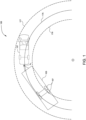
  • 1 eine Ein-Anhänger-Zugkonfiguration mit Spurabweichung gemäß der vorliegenden Erfindung;
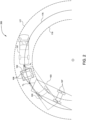
  • 2 eine Mehr-Anhänger-Zugkonfiguration und eine Vergleichs-Ein-Anhänger-Zugkonfiguration mit Spurabweichung gemäß der vorliegenden Erfindung;
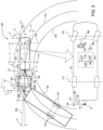
  • 3 eine Mehr-Anhänger-Zugkonfiguration mit Anhängernachführungssteuerung gemäß der vorliegenden Erfindung;
  • 4A-4D Ausführungsform eines Zwischenanhängers für eine Mehr-Anhänger-Zugkonfiguration mit Anhängernachführungssteuerung gemäß der vorliegenden Erfindung;
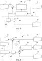
  • 5 einen beispielhaften Steuerprozess gemäß der vorliegenden Erfindung; und
  • 6 einen beispielhaften Steuerprozess gemäß der vorliegenden Erfindung.
Further features, advantages and details appear only as examples in the following detailed description, which refers to the drawings; they show:
  • 1 a single trailer train configuration with track deviation according to the present invention;
  • 2 a multi-trailer train configuration and a comparative single-trailer train configuration with track deviation according to the present invention;
  • 3 a multi-trailer train configuration with trailer tracking control according to the present invention;
  • 4A-4D Embodiment of an intermediate trailer for a multi-trailer train configuration with trailer tracking control according to the present invention;
  • 5 an exemplary control process according to the present invention; and
  • 6 an exemplary control process according to the present invention.

AUSFÜHRLICHE BESCHREIBUNGDETAILED DESCRIPTION

Die folgende Beschreibung ist dem Wesen nach lediglich beispielhaft. Einander entsprechende Bezugszeichen bezeichnen überall in den Zeichnungen gleiche oder einander entsprechende Teile und Merkmale. Wie Steuermodul, Modul, Steuerung, Controller, Steuereinheit, Prozessor und ähnliche Begriffe hier verwendet sind, bedeuten sie irgendeine oder verschiedene Kombinationen einer oder mehrerer anwendungsspezifischer integrierter Schaltungen (ASIC), elektronischer Schaltungen, Zentraleinheiten (vorzugsweise Mikroprozessoren) und zugeordnetem Speicher und Ablagespeicher (Nur-Lese-Speicher (ROM), Schreib-Lese-Speicher (RAM), elektrisch programmierbarem Nur-Lese-Speicher (EPROM), Festplattenlaufwerk usw.) oder Mikrocontrollern, die ein oder mehrere Software- oder Firmwareprogramme oder Software- oder Firmware-Routinen ausführen, Kombinationslogikschaltungen, einer Eingabe/Ausgabe-Schaltungsanordnung und von Eingabe/Ausgabe-Vorrichtungen (E/A) und einer geeignete Signalaufbereitungs- und Signalpufferschaltungsanordnung, eines schnellen Taktgebers, einer Analog-Digital-Schaltungsanordnung (A/D-Schaltungsanordnung) und einer Digital-Analog-Schaltungsanordnung (D/A-Schaltungsanordnung) und anderer Komponenten zur Bereitstellung der beschriebenen Funktionalität. Ein Steuermodul kann eine Vielzahl von Kommunikationsschnittstellen einschließlich Punktzu-Punkt-Leitungen oder diskreter Leitungen und verdrahteter oder drahtloser Schnittstellen zu Netzen einschließlich Weitverkehrsnetzen und lokalen Netzen, Fahrzeugnetzen (z. B. Controller Area Network (CAN), Local Interconnect Network (LIN) und Werks- und Kundendienst-bezogenen Netzen enthalten. Steuermodulfunktionen, wie sie in dieser Erfindung dargelegt sind, können in einer verteilten Steuerarchitektur unter mehreren vernetzten Steuermodulen ausgeführt werden. Software, Firmware, Programme, Anweisungen, Routinen, Code, Algorithmen und ähnliche Begriffe bedeuten irgendwelche durch einen Controller ausführbare Anweisungssätze einschließlich Kalibrierungen, Datenstrukturen und Nachschlagetabellen. Ein Steuermodul weist einen Satz von Steuerroutinen auf, die zur Bereitstellung beschriebener Funktionen ausgeführt werden. Routinen werden wie etwa durch eine Zentraleinheit ausgeführt und sind dafür betreibbar, Eingaben von Erfassungsvorrichtungen und anderen vernetzten Steuermodulen zu überwachen und Steuer- und Diagnoseroutinen zum Steuern des Betriebs von Aktuatoren auszuführen. Routinen können während des andauernden Kraftmaschinen- und Fahrzeugbetriebs in regelmäßigen Intervallen ausgeführt werden. Alternativ können Routinen in Ansprechen auf das Auftreten eines Ereignisses, auf Softwareaufrufe oder bei Bedarf über Benutzerschnittstelleneingaben oder Benutzerschnittstellenanforderungen ausgeführt werden.The following description is merely exemplary in nature. Corresponding reference characters designate like or corresponding parts and features throughout the drawings. As used herein, control module, module, controller, control unit, processor and similar terms mean any or various combinations of one or more application specific integrated circuits (ASICs), electronic circuits, central processing units (preferably microprocessors) and associated memory and storage (read only memory (ROM), random access memory (RAM), electrically programmable read only memory (EPROM), hard disk drive, etc.) or microcontrollers executing one or more software or firmware programs or software or executing firmware routines, combinational logic circuitry, input/output circuitry and input/output devices (I/O) and suitable signal conditioning and signal buffer circuitry, a high speed clock, analog-to-digital (A/D) circuitry and digital-to-analog (D/A) circuitry, and other components to provide the described functionality. A control module may include a variety of communication interfaces including point-to-point or discrete lines and wired or wireless interfaces to networks including wide area networks and local area networks, vehicle networks (e.g., Controller Area Network (CAN), Local Interconnect Network (LIN), and factory and service related networks. Control module functions as set forth in this invention may be performed in a distributed control architecture among multiple networked control modules. Software, firmware, programs, instructions, routines, code, algorithms, and similar terms mean any set of instructions executable by a controller, including calibrations, data structures, and lookup tables. A control module includes a set of control routines executed to provide described functions. Routines are executed, such as by a central processing unit, and are operable to monitor inputs from sensing devices and other networked control modules and to perform control and diagnostic routines to control the operation of actuators. Routines may be executed at regular intervals during ongoing engine and vehicle operation. Alternatively, routines may be executed in response to the occurrence of an event, to software calls, or on demand via user interface inputs or user interface requests.

1 stellt eine Ein-Anhänger-Zugkonfiguration 100 dar, die ein Zugfahrzeug 101 und einen Anhänger 103 enthält. Das Zugfahrzeug 101 und der Anhänger 103 sind bei einem Anhängerkupplungspunkt (H1) gekuppelt, der während Manövern um Kurven und Ecken die Gelenkbewegung des Anhängers 103 und des Zugfahrzeugs 101 zulässt. Ein-Anhänger-Zugkonfigurationen können einen bestimmten Grad einer Spurabweichung zeigen, der dadurch charakterisiert ist, dass die Anhängerräder 107 zu der Innenseite des Innenradwegs 175 des Zugfahrzeugs 101 nachführen. Ein bestimmter Grad an Spurabweichung kann akzeptabel sein. Allerdings kann der Betrag der Spurabweichung des Anhängers 103 verstärkt werden, während der Wenderadius des Zugfahrzeugs 101 verringert wird. Eine bestimmte Kompensation durch den Fahrer kann dadurch erhalten werden, dass das Zugfahrzeug 101 in Richtung der äußeren Fahrspurgrenze 177 gesteuert wird, was den verfügbaren Wenderadius maximiert. Allerdings kann der Anhänger 103 bei einem bestimmten Wenderadius außerhalb der inneren Fahrspurgrenze 179 von der Spur abweichen. 1 illustrates a single-trailer towing configuration 100 including a tow vehicle 101 and a trailer 103. The tow vehicle 101 and the trailer 103 are coupled at a hitch point (H 1 ) that allows for articulation of the trailer 103 and the tow vehicle 101 during maneuvers around curves and corners. Single-trailer towing configurations may exhibit a certain degree of tracking, characterized by the trailer wheels 107 tracking to the inside of the inside wheel path 175 of the tow vehicle 101. A certain degree of tracking may be acceptable. However, the amount of tracking of the trailer 103 may be increased while the turning radius of the tow vehicle 101 is reduced. Some compensation by the driver may be obtained by steering the tow vehicle 101 toward the outer lane boundary 177, which maximizes the available turning radius. However, the trailer 103 may deviate from the lane at a certain turning radius outside the inner lane boundary 179.

2 zeigt eine Mehr-Anhänger-Zugkonfiguration 200, die ein Zugfahrzeug 101, einen Anhänger 102 und einen Anhänger 103 enthält. Der Anhänger 102 ist zwischen dem Zugfahrzeug 101 und dem Anhänger 103. Das Zugfahrzeug 101 und der Zwischenanhänger 102 sind bei einem Anhängerkupplungspunkt (H1) gekuppelt, der während Manövern um Kurven und Ecken die Gelenkbewegung des Anhängers 102 und des Zugfahrzeugs 102 zulässt. Der Anhänger 102 und der Anhänger 103 sind mit einem Anhängerkupplungspunkt (H2) gekuppelt, der während Manövern um Kurven und Ecken die Gelenkbewegung des Anhängers 102 und des Anhängers 103 zulässt. Mehr-Anhänger-Zugkonfigurationen können einen bestimmten Grad von Spurabweichung zeigen, der dadurch charakterisiert ist, dass die Anhängerräder 107, 109 jedes jeweiligen Anhängers zu der Innenseite des Innenradwegs 175 des Zugfahrzeugs 101 nachführen. Ein bestimmter Grad an Spurabweichung kann akzeptabel sein. Allerdings kann der Betrag der Spurabweichung eines oder beider Anhänger 102, 103 verstärkt sein, während der Wenderadius des Zugfahrzeugs 101 verringert ist. Eine bestimmte Kompensation durch den Fahrer kann dadurch erhalten werden, dass er das Zugfahrzeug 101 in Richtung der äußeren Fahrspurgrenze 177 steuert, was den verfügbaren Wenderadius maximiert. Allerdings können bei einem bestimmten Wenderadius ein oder beide Anhänger 102, 103 außerhalb der inneren Fahrspurgrenze 179 von der Spur abweichen. Mehr-Anhänger-Konfigurationen können bei dem Anhänger 103, der am weitesten von dem Zugfahrzeug 101 ist, eine drastischere Spurabweichung zeigen und können eine drastischere Spurabweichung als Ein-Anhänger-Konfigurationen (1 und 2 der Anhänger 103 in Strichlinien) zeigen. 2 shows a multi-trailer towing configuration 200 that includes a tow vehicle 101, a trailer 102, and a trailer 103. The trailer 102 is between the tow vehicle 101 and the trailer 103. The tow vehicle 101 and the intermediate trailer 102 are coupled at a hitch point (H 1 ) that allows articulation of the trailer 102 and the tow vehicle 102 during maneuvers around curves and corners. The trailer 102 and the trailer 103 are coupled at a hitch point (H 2 ) that allows articulation of the trailer 102 and the trailer 103 during maneuvers around curves and corners. Multi-trailer towing configurations may exhibit a certain degree of tracking, characterized by the trailer wheels 107, 109 of each respective trailer tracking to the inside of the inner wheel path 175 of the tow vehicle 101. A certain degree of tracking may be acceptable. However, the amount of tracking of one or both trailers 102, 103 may be increased while the turning radius of the tow vehicle 101 is reduced. Some compensation by the driver may be obtained by steering the tow vehicle 101 toward the outer lane boundary 177, which maximizes the available turning radius. However, at a certain turning radius, one or both trailers 102, 103 may track outside the inner lane boundary 179. Multi-trailer configurations may exhibit more drastic track deviation on the trailer 103 that is furthest from the towing vehicle 101 and may exhibit more drastic track deviation than single-trailer configurations ( 1 and 2 the trailer 103 in dashed lines).

Gemäß der vorliegenden Erfindung sind hier und in den verschiedenen Zeichnungen eine Vorrichtung und ein Verfahren für die Anhängernachführungssteuerung in einer Mehr-Anhänger-Zugkonfiguration 300 dargelegt. 3 stellt eine Mehr-Anhänger-Zugkonfiguration 300 dar, die ein Zugfahrzeug 101, einen Anhänger 102 und einen Anhänger 103 enthält. Der Anhänger 102 ist zwischen dem Zugfahrzeug 101 und dem Anhänger 103. Das Zugfahrzeug 101 und der Anhänger 102 sind bei einem Anhängerkupplungspunkt (H1) gekuppelt, der während Manövern um Kurven und Ecken die Gelenkbewegung des Anhängers 102 und des Zugfahrzeugs 101 zulässt. Der Anhänger 102 und der Anhänger 103 sind bei einem Anhängerkupplungspunkt (H2) gekuppelt, der während Manövern um Kurven und Ecken die Gelenkbewegung des Anhängers 102 und des Anhängers 103 zulässt.In accordance with the present invention, there is set forth herein and in the various drawings an apparatus and method for trailer tracking control in a multiple trailer train configuration 300. 3 illustrates a multi-trailer towing configuration 300 including a towing vehicle 101, a trailer 102, and a trailer 103. The trailer 102 is coupled between the towing vehicle 101 and the trailer 103. The towing vehicle 101 and the trailer 102 are coupled at a hitch point (H 1 ) that allows for articulation of the trailer 102 and the towing vehicle 101 during maneuvers around curves and corners. The trailer 102 and the trailer 103 are coupled at a hitch point (H 1 ) that allows for articulation of the trailer 102 and the towing vehicle 101 during maneuvers around curves and corners. point (H 2 ) which allows the articulated movement of the trailer 102 and the trailer 103 during maneuvers around curves and corners.

Das Zugfahrzeug 101 kann im Folgenden als Fahrzeug 101 bezeichnet sein und ist bei einem Anhängerkupplungspunkt (H1) mit einer Gelenkverbindungs-Anhängerkupplung konfiguriert. Beispielhafte Gelenkverbindungs-Anhängerkupplungen bei dem Anhängerkupplungspunkt (H1) können eine Aufnahme-Anhängerkupplung 106 mit Kugel und einer komplementären Deichsel 104F des vorderen Anhängers mit einer Kugelpfannenkupplung oder ein an einer Pickup-Ladefläche montierter Schwanenhals und Sattelkupplungen sein. In irgendeiner Konfiguration sind der Anhänger 102 und das Fahrzeug 101 bei dem Anhängerkupplungspunkt (H1) gelenkig verbunden. Eine beispielhafte Gelenkverbindungs-Anhängerkupplung bei dem Anhängerkupplungspunkt (H2) kann eine Deichsel 104R des hinteren Anhängers mit einer Kugel und eine komplementäre Deichsel 108F des vorderen Anhängers mit Kugelpfannenkupplung enthalten. Zum Beispiel kann die Gelenkverbindungs-Anhängerkupplung bei dem Anhängerkupplungspunkt (H2) alternativ einen Schwanenhals oder eine Sattelkupplung enthalten. In irgendeiner Konfiguration sind das Fahrzeug 101 und der Anhänger 102 bei dem Anhängerkupplungspunkt (H1) gelenkig verbunden und sind der Anhänger 102 und der Anhänger 103 bei dem Anhängerkupplungspunkt (H2) gelenkig verbunden. Das Fahrzeug 101 kann ein Vierradfahrzeug sein, das an jeder Ecke einen Reifen und ein Rad 105 enthält. Wie es hier verwendet ist, soll die Bezugnahme auf ein Rad oder auf einen Reifen so verstanden sein, dass sie, sofern nicht etwas anderes spezifisch genannt ist, ein Rad- und Reifenkomplement bedeutet. Der Anhänger 103 ist als ein Zweiachsenanhänger dargestellt, der auf jeder Querseite zwei Räder 107 enthält. Der Anhänger 102 ist ebenfalls als ein Zweiachsenanhänger dargestellt, der auf jeder Querseite zwei Räder 109 enthält. Die Anhänger 102, 103 sind beispielhaft und es ist zu verstehen, dass alternative Anhängerkonfigurationen z. B. mehr oder weniger Achsen enthalten können. Wie es hier verwendet ist, ist Achse so zu verstehen, dass sie ein Paar seitlich gegenüberliegender Räder an einem Fahrzeug oder Anhänger bedeutet, die nicht notwendig eine physische Achse dazwischen enthalten. Somit weist das Fahrzeug 101 eine Vorderachse 116, die zwei Vorderräder enthält, und eine Hinterachse 114, die zwei Hinterräder enthält, auf. Der Anhänger 103 weist ein Paar Achsen 118 auf, die vier Räder enthalten, und der Anhänger 102 weist ein Paar Achsen 120 auf, die vier Räder enthalten. Außerdem kann sich Rad, wie es hier verwendet ist, auf ein einzelnes Rad oder mehrere Räder auf einer Seite einer Achse, z. B. eine Pickup-Achse mit Zwillingsreifen oder auf einen Ein- oder Mehrachsenanhänger mit Zwillingsreifen, beziehen.The tow vehicle 101 may be referred to hereinafter as vehicle 101 and is configured with an articulating hitch at a hitch point (H 1 ). Example articulating hitches at the hitch point (H 1 ) may include a receiver hitch 106 with a ball and a complementary front trailer tongue 104F with a ball socket hitch or a pickup bed mounted gooseneck and fifth wheels. In any configuration, the trailer 102 and the vehicle 101 are articulatingly connected at the hitch point (H 1 ). An example articulating hitch at the hitch point (H 2 ) may include a rear trailer tongue 104R with a ball and a complementary front trailer tongue 108F with a ball socket hitch. For example, the articulating hitch may alternatively include a gooseneck or fifth wheel at the hitch point (H 2 ). In any configuration, the vehicle 101 and trailer 102 are articulatingly connected at the hitch point (H 1 ) and the trailer 102 and trailer 103 are articulatingly connected at the hitch point (H 2 ). The vehicle 101 may be a four-wheel vehicle including a tire and a wheel 105 at each corner. As used herein, reference to a wheel or to a tire is to be understood to mean a wheel and tire complement unless otherwise specifically stated. The trailer 103 is shown as a two-axle trailer including two wheels 107 on each transverse side. The trailer 102 is also shown as a two-axle trailer including two wheels 109 on each transverse side. Trailers 102, 103 are exemplary, and it is understood that alternative trailer configurations may include more or fewer axles, for example. As used herein, axle is understood to mean a pair of laterally opposed wheels on a vehicle or trailer that do not necessarily include a physical axle therebetween. Thus, vehicle 101 includes a front axle 116 that includes two front wheels and a rear axle 114 that includes two rear wheels. Trailer 103 includes a pair of axles 118 that include four wheels, and trailer 102 includes a pair of axles 120 that include four wheels. Additionally, wheel, as used herein, may refer to a single wheel or multiple wheels on one side of an axle, such as a pickup truck axle with dual tires or a single or multi-axle trailer with dual tires.

Das Fahrzeug 101 kann eine Steuersystemarchitektur 135 enthalten, die mehrere elektronische Steuereinheiten (ECU) 137 enthält, die über eine Vielzahl geeigneter verdrahteter und/oder drahtloser Netze, z. B. über eine Busstruktur 139, kommunikationstechnisch gekoppelt sein können, um Steuerfunktionen und gemeinsame Nutzung von Informationen einschließlich der Ausführung von Steuerroutinen lokal und auf verteilte Weise auszuführen. Die Busstruktur 139 kann ein Controller Area Network (CAN) enthalten, wie es der Durchschnittsfachmann kennt. Die ECUs 137 können derartige Beispiele wie ein Antriebsstrangsteuermodul (PCM), ein Kraftmaschinensteuermodul (ECM), ein Getriebesteuermodul (TCM), ein Karosseriesteuermodul (BCM), ein Lenkungssteuermodul (SCM), ein Steuermodul der elektrischen Antriebseinheit, ein Traktionssteuerungs- oder Stabilitätssteuerungsmodul, ein Tempomatmodul, ein Bremssteuermodul usw. enthalten. Gemäß einer Ausführungsform kann das Lenkungssteuermodul (SCM) 141 eine beispielhafte ECU 137 sein, die primär die Aufgabe von Funktionen hat, die sich auf die Anhängernachführungs-Steuersystem-Überwachung, Anhängernachführungs-Steuersystem-Steuerung und Anhängernachführungs-Steuersystem-Diagnose gemäß der vorliegenden Erfindung beziehen. Die ECUs 137 einschließlich des SCM 141 können mit einer Vielzahl von Sensoren und Aktuatoren sowie irgendeiner Kombination der anderen ECUs (z. B. über die Busstruktur 139 und/oder über andere verdrahtete und/oder drahtlose Netze) indirekt oder direkt verbunden sein.The vehicle 101 may include a control system architecture 135 that includes a plurality of electronic control units (ECUs) 137 that may be communicatively coupled via a variety of suitable wired and/or wireless networks, e.g., via a bus structure 139, to perform control functions and information sharing, including execution of control routines, locally and in a distributed manner. The bus structure 139 may include a controller area network (CAN), as known to those of ordinary skill in the art. The ECUs 137 may include such examples as a powertrain control module (PCM), an engine control module (ECM), a transmission control module (TCM), a body control module (BCM), a steering control module (SCM), an electric drive unit control module, a traction control or stability control module, a cruise control module, a brake control module, etc. According to one embodiment, the steering control module (SCM) 141 may be an exemplary ECU 137 primarily tasked with functions related to trailer tracking control system monitoring, trailer tracking control system control, and trailer tracking control system diagnostics in accordance with the present invention. The ECUs 137, including the SCM 141, may be indirectly or directly connected to a variety of sensors and actuators, as well as any combination of the other ECUs (e.g., via the bus structure 139 and/or via other wired and/or wireless networks).

Das SCM 141 kann von Sensoren und von anderen ECUs 137 eine Vielzahl von Informationen zur Verwendung in der Anhängernachführungssteuerung empfangen. Informationen, die durch das SCM 141 empfangen werden, können derartige Beispiele wie dynamische und kinematische Informationen des Fahrzeugs 101 wie etwa die Fahrzeuggeschwindigkeit, die Fahrzeugfahrtrichtung, den Fahrzeuglenkwinkel, Fahrzeugmehrachsen-Beschleunigungen und Fahrzeugmehrachsen-Rucke, Fahrzeuggieren, Fahrzeugnicken, Fahrzeugwanken und ihre abgeleiteten Größen usw. enthalten. Viele derartige Größen können allgemein über die Fahrzeugbusstruktur 139 verfügbar sein, wobei sie von bekannten Fahrzeugsensoren ausgehen oder in dem SCM 141 oder in einer anderen ECU 137 (z. B. dem Traktions-, dem Stabilitätssteuerungs- und/oder dem Bremsmodul) davon abgeleitet werden. Derartige Sensoren können z. B. Raddrehzahlsensoren bei jedem Rad des Fahrzeugs 101, den Lenkwinkelsensor 181 und den Trägheitsmessungssensor 188 enthalten. Einige Sensoren können Informationen als direkte Eingaben in das SCM 141 bereitstellen, während andere Informationen über die Busstruktur 139 bereitstellen können, wobei z. B. ein Sensor als eine Netzknotenvorrichtung arbeiten kann oder wobei derartige Informationen auf der Busstruktur über eine andere ECU 137 allgemein verfügbar sind.The SCM 141 may receive a variety of information from sensors and from other ECUs 137 for use in trailer tracking control. Information received by the SCM 141 may include such examples as dynamic and kinematic information of the vehicle 101 such as vehicle speed, vehicle heading, vehicle steering angle, vehicle multi-axis accelerations and jerks, vehicle yaw, vehicle pitch, vehicle roll and their derived quantities, etc. Many such quantities may be generally available via the vehicle bus structure 139, originating from known vehicle sensors or derived therefrom in the SCM 141 or in another ECU 137 (e.g., the traction, stability control and/or braking module). Such sensors may include, for example, wheel speed sensors at each wheel of the vehicle 101, the steering angle sensor 181, and the inertial measurement sensor 188. Some sensors may provide information as direct inputs to the SCM 141, while others may provide information via the bus structure 139, for example, where a sensor may be a network node device or where such information is generally available on the bus structure via another ECU 137.

Die Vorderradlenkung des Fahrzeugs 101 kann durch einen Vorderradlenkmechanismus 180 beeinflusst werden, der ein Lenkgetriebe und Lenkgestänge, wie sie im Gebiet bekannt sind, enthalten kann. Außerdem kann das Fahrzeug 101 ein aktives Hinterradlenkungssystem enthalten. Die Betreiberlenkungseingabe kann über ein Lenkrad und eine mechanische Lenkwelle, die mit dem Lenkgetriebe zusammenwirkt, erfolgen. Die mechanische Lenkanstrengung kann durch hydraulische oder elektrische Vorrichtungen unterstützt werden. Es sind Steer-bywire-Systeme bekannt, bei denen die Betreiberlenkabsicht bestimmt wird und zusammen mit anderen Informationen wie etwa der Fahrzeuggeschwindigkeit (V) und der Gierrate (ω) eine Zahnstange ohne die Notwendigkeit einer mechanischen Lenkwelle, die mit dem Lenkgetriebe zusammenwirkt, betätigt.The front wheel steering of the vehicle 101 may be influenced by a front wheel steering mechanism 180, which may include a steering gear and steering linkages as are known in the art. In addition, the vehicle 101 may include an active rear wheel steering system. The operator steering input may be via a steering wheel and a mechanical steering shaft that cooperates with the steering gear. The mechanical steering effort may be assisted by hydraulic or electrical devices. Steer-by-wire systems are known in which the operator steering intention is determined and, together with other information such as vehicle speed (V) and yaw rate (ω), actuates a steering rack without the need for a mechanical steering shaft that cooperates with the steering gear.

Die in 3 dargestellte Zugkonfiguration 300 enthält ein Fahrzeug 101, einen Anhänger 102 und einen Anhänger 103, die bei Anhängerkupplungspunkten (H1) und (H2) gelenkig gekuppelt sind. In 3 sind verschiedene geometrische Beziehungen der Zugkonfiguration dargestellt. Das Fahrzeug 101 weist eine Fahrzeuglängsmittellinie 201 auf und der Anhänger 102 weist eine Anhängerlängsmittellinie 203 auf. Jede jeweilige Mittellinie 201, 203 geht durch einen Zugkonfigurations-Anhängerkupplungspunkt (H1). Zwischen der Anhängermittellinie 203 und der Fahrzeugmittellinie 201 ist ein Anhängerkupplungs-Knickwinkel (θ1) definiert und dieser ist ein Maß für die Ausrichtungsabweichung oder Gelenkbewegung zwischen dem Anhänger 102 und dem Fahrzeug 101. Während die Zugkonfiguration auf einer Geraden fährt, ist der Anhängerkupplungs-Knickwinkel (θ1) im Wesentlichen null, und während die Zugkonfiguration um Kurven oder Ecken fährt, ist er von null verschieden. Die Anhängerkupplungs-Knickwinkel-Erfassung (Anhängerkupplungs-θ1-Erfassung) ist dem Fachmann bekannt und kann als Beispiele durch einen Drehsensor 112 wie etwa einen Codierer oder ein Potentiometer oder ein Bildverarbeitungssystem 113, das eine Kamera enthält, bereitgestellt werden. Der Drehsensor 112, das Bildverarbeitungssystem 113 oder ein alternativer Anhängerkupplungs-Knickwinkel-Sensor (Anhängerkupplungs-θ1-Sensor) können z. B. über die Busstruktur 139 Anhängerkupplungs-Knickwinkel-Informationen (Anhängerkupplungs-θ1-Informationen) für das SCM 141 bereitstellen. Die Vorderachse 116 des Fahrzeugs 101 schneidet die Fahrzeugmittellinie 201 im Punkt (A). Der Punkt (A) kann als der Fahrzeug-Vorderachsen-Mittelpunkt (A) bezeichnet werden. Die Hinterachse 114 des Fahrzeugs 101 schneidet die Fahrzeugmittellinie 201 im Punkt (B). Der Punkt (B) kann als der Fahrzeug-Hinterachsen-Mittelpunkt (B) bezeichnet werden. Der Abstand zwischen der Vorderachse 116 und der Hinterachse 114 des Fahrzeugs 101, d. h. der Abstand zwischen den Mittelpunkten (A) und (B), ist mit (L1) bezeichnet und kann als der Fahrzeugradstand bezeichnet werden. Der Abstand zwischen dem Hinterachsenmittelpunkt (B) und dem Anhängerkupplungspunkt (H1) entlang der Fahrzeugmittellinie 201 ist als (d) bezeichnet. Der Abstand zwischen dem Anhängerkupplungspunkt (H1) und dem Anhängerkupplungspunkt (H2) entlang der Mittellinie 203 des Anhängers 102 ist durch (L2) bezeichnet und kann als die Länge des Anhängers 102 bezeichnet werden. Gemäß einer Ausführungsform kann eine äußerste vordere Ecke (CV) des Fahrzeugs 101 eine äußere Wendeumfangsreferenz oder einen äußeren Wendeumfangsgrenzwert bereitstellen, die bzw. der als ein freier Weg für die Anhänger 102, 103 angesehen wird. Außerdem kann eine äußerste hintere Ecke (CT) des Anhängers 102 als ein Grenzwert an die Nachführung des Anhängers 102 definiert sein. Der Abstand zwischen dem Anhängerkupplungspunkt (H1) und der äußersten rechten Ecke (CT) des Anhängers 102 ist durch (L3) bezeichnet. Die äußerste vordere Ecke (CV) des Fahrzeugs 101 kann relativ zu einem Längsabstand (a) vor dem Vorderachsenmittelpunkt (A) und einem seitlichen Abstand (b) von dem Vorderachsenmittelpunkt (A) in Richtung der Außenseite der aktuellen Richtungsänderung definiert sein. Ähnlich kann die äußerste hintere Ecke (CT) relativ zu einem Längsabstand (c) von dem Anhängerkupplungspunkt (H2) und einem seitlichen Abstand (e) von dem Anhängerkupplungspunkt (H2) in Richtung der Außenseite der aktuellen Fahrtrichtungsänderung definiert sein. Der Lenkwinkelsensor 181 kann einen Lenkwinkel (δV) der Vorderräder des Fahrzeugs 101 bereitstellen. Für Ausführungsformen, in denen der Anhänger 102 lenkbare Räder enthält, ist ein Lenkwinkel der Räder des Anhängers 102 als (δT) bezeichnet.The in 3 The train configuration 300 shown includes a vehicle 101, a trailer 102 and a trailer 103, which are articulatedly coupled at trailer coupling points (H 1 ) and (H 2 ). In 3 , various geometric relationships of the train configuration are illustrated. The vehicle 101 has a vehicle longitudinal centerline 201 and the trailer 102 has a trailer longitudinal centerline 203. Each respective centerline 201, 203 passes through a train configuration hitch point (H 1 ). A hitch articulation angle (θ 1 ) is defined between the trailer centerline 203 and the vehicle centerline 201 and is a measure of the misalignment or articulation between the trailer 102 and the vehicle 101. While the train configuration is traveling in a straight line, the hitch articulation angle (θ 1 ) is essentially zero, and while the train configuration is traveling around curves or corners, it is nonzero. Hitch articulation angle sensing (hitch θ 1 sensing) is known to those skilled in the art and may be provided by, as examples, a rotation sensor 112 such as an encoder or potentiometer, or an image processing system 113 including a camera. The rotation sensor 112, the image processing system 113, or an alternative hitch articulation angle sensor (hitch θ 1 sensor) may provide hitch articulation angle information (hitch θ 1 information) to the SCM 141, for example, via the bus structure 139. The front axle 116 of the vehicle 101 intersects the vehicle centerline 201 at point (A). The point (A) may be referred to as the vehicle front axle center point (A). The rear axle 114 of the vehicle 101 intersects the vehicle centerline 201 at point (B). Point (B) may be referred to as the vehicle rear axle center (B). The distance between the front axle 116 and the rear axle 114 of the vehicle 101, that is, the distance between the centers (A) and (B), is denoted by (L 1 ) and may be referred to as the vehicle wheelbase. The distance between the rear axle center (B) and the trailer hitch point (H 1 ) along the vehicle centerline 201 is denoted by (d). The distance between the trailer hitch point (H 1 ) and the trailer hitch point (H 2 ) along the centerline 203 of the trailer 102 is denoted by (L 2 ) and may be referred to as the length of the trailer 102. According to an embodiment, a frontmost corner (C V ) of the vehicle 101 may provide an outside turning circumference reference or limit that is considered a clear path for the trailers 102, 103. Additionally, a rearmost corner (C T ) of the trailer 102 may be defined as a limit to the tracking of the trailer 102. The distance between the trailer hitch point (H 1 ) and the rightmost corner (C T ) of the trailer 102 is denoted by (L 3 ). The frontmost corner (C V ) of the vehicle 101 may be defined relative to a longitudinal distance (a) forward of the front axle center (A) and a lateral distance (b) from the front axle center (A) toward the outside of the current turn. Similarly, the rearmost corner (C T ) may be defined relative to a longitudinal distance (c) from the hitch point (H 2 ) and a lateral distance (e) from the hitch point (H 2 ) toward the outside of the current turn. The steering angle sensor 181 may provide a steering angle (δ V ) of the front wheels of the vehicle 101. For embodiments in which the trailer 102 includes steerable wheels, a steering angle of the wheels of the trailer 102 is denoted as (δ T ).

Gemäß einer Ausführungsform kann das Anhängernachführungssteuersystem das SCM 141 enthalten, das Steuerroutinen, verschiedene Sensoren und/oder Sensorinformationen und den Anhänger 102 zwischen dem Fahrzeug und dem Anhänger 103 enthält. Der Anhängerkupplungs-Knickwinkel (θ1) kann mit einem Ziel der Verringerung der Spurabweichung des Anhängers 103 auf einen (im Folgenden diskutierten) Ziel-Anhängerkupplungs-Knickwinkel (θ1-target) gesteuert werden. Gemäß einer Ausführungsform kann der Anhänger 102 nicht lenkbare Räder enthalten. Gemäß einer anderen Ausführungsform kann der Anhänger 102 lenkbare Räder enthalten. Gemäß einer Ausführungsform kann der Anhänger 102 ein Reibungsbremssystem zum Anwenden eines Bremsmoments auf die Räder enthalten. Gemäß einer Ausführungsform kann der Anhänger 102 ein Vortriebssystem zum Anwenden eines Traktionsmoments auf ein oder mehrere Räder enthalten. Wie es hier verwendet ist, kann ein Traktionsmoment ein Vortriebsmoment und/oder ein Bremsmoment enthalten.According to one embodiment, the trailer tracking control system may include the SCM 141, which includes control routines, various sensors and/or sensor information, and the trailer 102 between the vehicle and the trailer 103. The hitch articulation angle (θ 1 ) may be controlled with a goal of reducing the track deviation of the trailer 103 to a target hitch articulation angle (θ 1-target ) (discussed below). According to one embodiment, the trailer 102 may include non-steerable wheels. According to another embodiment, the trailer 102 may include steerable wheels. According to one embodiment, the trailer 102 may include a friction braking system for applying braking torque to the wheels. According to one embodiment, the trailer 102 may include a propulsion system for applying traction torque to one or more wheels. As used herein, a traction torque may include a propulsion torque and/or a braking torque.

Die 4A-4D stellen einzelne Lenkungs-, Reibungsbrems- und Vortriebssysteme dar, die in dem Anhänger 102 allein oder in verschiedenen Kombinationen enthalten sein können. 4A stellt eine Ausführungsform lenkbarer Räder an dem Anhänger 102 dar. Die Radlenkung kann durch ein Anhängerlenkungssystem 115 beeinflusst werden, das ein Lenkgetriebe und Lenkgestänge enthalten kann. Das Anhängerlenkungssystem 115 kann einen Aktuator 117 enthalten, der veranlasst, dass das Lenkgetriebe die Räder des Anhängers 102 in die gewünschte Richtung lenkt. Gemäß einer Ausführungsform kann der Aktuator 117 z. B. ein Dreh- oder Linearelektromotor oder ein Hydraulikaktuator oder eine Kombination wie etwa ein elektrohydraulischer Aktuator sein. Dem Durchschnittsfachmann können andere Aktuatoren bekannt sein. Gemäß einer anderen Ausführungsform kann das Anhängerlenkungssystem 115 einzelne Mechanismen mit einem Aktuator am Rad wie etwa unabhängigen elektrischen Aktuatoren enthalten. Der Aktuator 117 ist entweder direkt oder wie dargestellt über die Busstruktur 139, die Steuerbefehle für den Aktuator 117 bereitstellen kann, mit dem SCM 141 kommunikationstechnisch gekoppelt. Ähnlich kann die Anhängerlenkungssystem-Rückkopplung wie etwa der Lenkwinkel (δT) für das SCM 141 bereitgestellt werden. Eine verdrahtete Kommunikation kann über einen Fahrzeug-Anhänger-Kabelbaum erfolgen. Die Kommunikation zwischen den Systemen des Anhängers 102 und dem Fahrzeug 101 kann durch drahtlose Vernetzung ausgeführt werden. 4B stellt eine Ausführungsform eines elektrischen Vortriebssystems an dem Anhänger 102 dar. Der Radvortrieb kann durch ein Anhängervortriebssystem 125 beeinflusst werden, das eine Antriebseinheit 127 und einen Controller 129 enthalten kann. Die Antriebseinheit kann z. B. einen Elektromotor (M), Leistungselektronik und Untersetzungs- und Differentialzahnradgetriebe für das Anwenden eines Vortriebsmoments auf ein oder mehrere Räder des Anhängers 102 enthalten. Das Differentialzahnradgetriebe kann ein Torque-Vectoring-Differentialzahnradgetriebe enthalten, das eine unabhängige Drehmomentsteuerung bei jedem Rad zulässt. Der Controller 129 ist entweder direkt oder wie dargestellt über die Busstruktur 139, die Steuerbefehle für den Controller 129 bereitstellen kann, kommunikationstechnisch mit dem SCM 141 gekuppelt. Die verdrahtete Kommunikation kann über einen Fahrzeug-Anhänger-Kabelbaum erfolgen. Die Kommunikation zwischen den Systemen des Anhängers 102 und dem Fahrzeug 101 kann durch drahtlose Vernetzung ausgeführt werden. 4C stellt eine Ausführungsform eines elektrischen Vortriebssystems an dem Anhänger 102 dar. Der Radvortrieb kann durch ein Anhängervortriebssystem 145 bewirkt werden, das einen Motor (M) pro Rad und einen Controller 149 enthalten kann. Der Controller 149 kann z. B. Leistungselektronik zum Steuern des Vortriebsmoments bei jedem mit einem Motor ausgestatteten Rad des Anhängers 102 enthalten. Der Controller 149 ist entweder direkt oder wie dargestellt über die Busstruktur 139, die Steuerbefehle für den Controller 149 bereitstellen kann, mit dem SCM 141 kommunikationstechnisch gekoppelt. Die verdrahtete Kommunikation kann über einen Fahrzeug-Anhänger-Kabelbaum erfolgen. Die Kommunikation zwischen den Systemen des Anhängers 102 und dem Fahrzeug 101 kann durch drahtlose Vernetzung ausgeführt werden. 4D stellt eine Ausführungsform eines Reibungsbremssystems an dem Anhänger 102 dar. Die Radbremsung kann durch ein Bremssystem 155 bewirkt werden, das einen Bremsaktuator 156 pro Rad und einen Controller 159 enthalten kann. Die Bremsaktuatoren 156 können elektrisch, hydraulisch oder irgendein anderer geeigneter Aktuator sein. Der Controller 159 kann z. B. Leistungselektronik oder hydraulische Steuerungen zum Steuern des Bremsmoments bei jedem mit einer Bremse ausgestatteten Rad des Anhängers 102 enthalten. Der Controller 159 ist entweder direkt oder wie dargestellt über die Busstruktur 139, die Steuerbefehle für den Controller 159 bereitstellen kann, kommunikationstechnisch mit dem SCM 141 gekoppelt. Die verdrahtete Kommunikation kann über einen Fahrzeug-Anhänger-Kabelbaum erfolgen. Die Kommunikation zwischen den Systemen des Anhängers 102 und dem Fahrzeug 101 kann über drahtlose Vernetzung ausgeführt werden.The 4A-4D represent individual steering, friction braking and propulsion systems that may be included in the trailer 102 alone or in various combinations. 4A illustrates one embodiment of steerable wheels on the trailer 102. Wheel steering may be influenced by a trailer steering system 115, which may include a steering gear and steering linkage. The trailer steering system 115 may include an actuator 117 that causes the steering gear to steer the wheels of the trailer 102 in the desired direction. According to one embodiment, the actuator 117 may be, for example, a rotary or linear electric motor or a hydraulic actuator, or a combination such as an electro-hydraulic actuator. Other actuators may be known to those of ordinary skill in the art. According to another embodiment, the trailer steering system 115 may include individual mechanisms with an actuator on the wheel, such as independent electric actuators. The actuator 117 is communicatively coupled to the SCM 141 either directly or, as shown, via the bus structure 139, which may provide control commands to the actuator 117. Similarly, trailer steering system feedback such as steering angle (δ T ) may be provided to the SCM 141. Wired communication may be accomplished via a vehicle-trailer harness. Communication between the systems of the trailer 102 and the vehicle 101 may be accomplished through wireless networking. 4B illustrates one embodiment of an electric propulsion system on the trailer 102. Wheel propulsion may be influenced by a trailer propulsion system 125, which may include a drive unit 127 and a controller 129. The drive unit may include, for example, an electric motor (M), power electronics, and reduction and differential gearing for applying propulsion torque to one or more wheels of the trailer 102. The differential gearing may include a torque vectoring differential gearing that allows independent torque control at each wheel. The controller 129 is communicatively coupled to the SCM 141 either directly or, as shown, via the bus structure 139, which may provide control commands to the controller 129. Wired communication may be via a vehicle-trailer wiring harness. Communication between the systems of the trailer 102 and the vehicle 101 may be accomplished through wireless networking. 4C illustrates one embodiment of an electric propulsion system on the trailer 102. Wheel propulsion may be accomplished by a trailer propulsion system 145, which may include a motor (M) per wheel and a controller 149. The controller 149 may include, for example, power electronics for controlling the propulsion torque at each motor-equipped wheel of the trailer 102. The controller 149 is communicatively coupled to the SCM 141 either directly or, as shown, via the bus structure 139, which may provide control commands to the controller 149. Wired communication may be accomplished via a vehicle-trailer wiring harness. Communication between the systems of the trailer 102 and the vehicle 101 may be accomplished through wireless networking. 4D illustrates one embodiment of a friction braking system on the trailer 102. Wheel braking may be accomplished by a braking system 155, which may include a brake actuator 156 per wheel and a controller 159. The brake actuators 156 may be electric, hydraulic, or any other suitable actuator. The controller 159 may include, for example, power electronics or hydraulic controls for controlling the braking torque at each brake-equipped wheel of the trailer 102. The controller 159 is communicatively coupled to the SCM 141 either directly or, as shown, via the bus structure 139, which may provide control commands to the controller 159. Wired communication may be via a vehicle-trailer wiring harness. Communication between the systems of the trailer 102 and the vehicle 101 may be accomplished via wireless networking.

5 stellt einen beispielhaften Steuerprozess 500 dar, der auf die in 3 dargestellte beispielhafte Zugkonfiguration 300, die den mit einem Anhängerlenkungssystem ausgestatteten Anhänger 102 enthält, anwendbar ist. Der Anhänger 102 kann mit einem oder mehreren eines Vortriebssystems und eines Bremssystems zum Anwenden eines Traktionsmoments auf ein oder mehrere Räder wie hier beschrieben ausgestattet sein. Der Steuerprozess 500 kann einen Vorwärtskopplungsabschnitt 502 und einen Rückkopplungsabschnitt 504 enthalten. Gemäß einer Ausführungsform ist nur der Vorwärtskopplungsabschnitt 502 implementiert, um eine Steuerung des Anhängerlenkungssystems bereitzustellen. Gemäß einer anderen Ausführungsform ist zusammen mit dem Vorwärtskopplungsabschnitt 502 der Rückkopplungsabschnitt 504 implementiert, um eine Regelung des Anhängerlenkungssystems bereitzustellen. Bei der Bestimmung des Ziel-Anhängerkupplungs-Knickwinkels (θ1-target) 507 kann der Fahrzeuglenkwinkel (δV) 501 (z. B. von dem Lenkwinkelsensor 181) verwendet werden. Bei der Bestimmung eines Ziel-Lenkwinkels (δT-target) 505 der Räder des Anhängers 102 können der Fahrzeuglenkwinkel (δV) 501 und der Ziel-Anhängerkupplungs-Knickwinkel (θ1-target) 507 verwendet werden. Gemäß einer reinen Vorwärtskopplungsimplementierung kann der Ziel-Lenkwinkel (δT-target) 505 bei der Bestimmung eines Lenkwinkelbefehls (δT-command) 511 für das Lenkungssystem des Anhängers 102 direkt genutzt werden. In einer Regelung des Anhängerlenkungssystems kann der Anhängerkupplungs-Knickwinkel (θ1) 503 (z. B. von dem Drehsensor 112) bei der Bestimmung eines Anhängerkupplungs-Knickwinkel-Fehlers zusammen mit dem Ziel-Anhängerkupplungs-Knickwinkel (θ1-target) 507 bei dem Summierknoten 506 verwendet werden. Dieser Fehler kann durch die PID-Regelung 509 bei der Bestimmung einer Einstellung auf den Ziel-Lenkwinkel (δT-target) 505 bei dem Summierknoten 508 verarbeitet werden. Der eingestellte Ziel-Lenkwinkel (δT-target) von dem Knoten 508 kann daraufhin bei der Bestimmung eines Lenkwinkelbefehls (δT-command) 511 für das Lenkungssystem des Anhängers 102 genutzt werden. Die PID-Regelung 509 ist beispielhaft und der Fachmann versteht, dass eine alternative Fehlerverarbeitungsregelung genutzt werden kann. 5 illustrates an exemplary control process 500 that is based on the 3 illustrated example towing configuration 300 including trailer 102 equipped with a trailer steering system. Trailer 102 may be equipped with one or more of a propulsion system and a braking system for applying traction torque to one or more wheels as described herein. Control process 500 may include a feedforward portion 502 and a feedback portion 504. According to one embodiment, only feedforward portion 502 is implemented to provide control of the trailer steering system. According to another embodiment, feedback portion 504 is implemented along with feedforward portion 502 to provide closed-loop control of the trailer steering system. In determining target hitch articulation angle (θ 1-target ) 507, vehicle steering angle (δ V ) 501 (e.g., from steering angle sensor 181) may be used. In determining a target steering angle (δ T-target ) 505 of the wheels of the trailer 102, the vehicle steering angle (δ V ) 501 and the target trailer coupling articulation angle (θ 1-target ) 507 may be used. According to a pure feedforward implementation, the Target steering angle (δ T-target ) 505 can be used directly in determining a steering angle command (δ T-command ) 511 for the steering system of the trailer 102. In a control of the trailer steering system, the trailer hitch articulation angle (θ 1 ) 503 (e.g., from the rotation sensor 112) can be used in determining a trailer hitch articulation angle error together with the target trailer hitch articulation angle (θ 1-target ) 507 at the summing node 506. This error can be processed by the PID controller 509 in determining an adjustment to the target steering angle (δ T-target ) 505 at the summing node 508. The set target steering angle (δ T-target ) from node 508 may then be used in determining a steering angle command (δ T-command ) 511 for the steering system of trailer 102. PID control 509 is exemplary and those skilled in the art will understand that an alternative error processing control may be used.

Gemäß einer Ausführungsform kann der Ziel-Anhängerkupplungs-Knickwinkel (θ1-target) in Übereinstimmung mit den folgenden Beziehungen bestimmt werden: θ 1 t a r g e t = sin 1 λ tan δ v d 2 ( tan δ v ) 2 + L 1 2 tan 1 e L 2 c cos 1 L 1 d 2 ( tan δ v ) 2 + L 1 2 ,

Figure DE102021130552B4_0008
λ = ( α + L 1 ) 2 ( L 3 2 + d 2 ) + 2 b L 1 tan δ v + b 2 2 L 3 ,
Figure DE102021130552B4_0009
L 3 = ( L 2 c ) 2 + e 2 ,
Figure DE102021130552B4_0010
wobei:

  • L1 der Radstand des Fahrzeugs 101 ist;
  • L2 die Länge des Anhängers 102 ist;
  • L3 der Abstand zwischen dem Anhängerkupplungspunkt (H1) und der äußersten hinteren Ecke (CT) des Anhängers 102 ist;
  • δV der Lenkwinkel des Fahrzeugs 101 ist;
  • a der Längsabstand vor dem Fahrzeug 101 von dem Vorderachsenmittelpunkt (A) des Fahrzeugs 101 zu der äußersten vorderen Ecke (CV) des Fahrzeugs 101 in Richtung der Außenseite der aktuellen Fahrtrichtungsänderung ist;
  • b der seitliche Abstand von dem Vorderachsenmittelpunkt (A) des Fahrzeugs 101 zu der äußersten vorderen Ecke (CV) des Fahrzeugs 101 in Richtung der Außenseite der aktuellen Fahrtrichtungsänderung ist;
  • c der Längsabstand von dem Anhängerkupplungspunkt (H2) zu der äußersten hinteren Ecke (CT) an dem Anhänger 102 in Richtung der Außenseite der aktuellen Fahrtrichtungsänderung ist;
  • d der Abstand zwischen einem Hinterachsenmittelpunkt (B) und dem Anhängerkupplungspunkt (H1) entlang der Fahrzeugmittellinie 201 ist; und
  • e der seitliche Abstand von dem Anhängerkupplungspunkt (H2) zu der äußersten hinteren Ecke (CT) an dem Anhänger 102 in Richtung der Außenseite der aktuellen Fahrtrichtungsänderung ist.
According to one embodiment, the target trailer hitch articulation angle (θ 1-target ) may be determined in accordance with the following relationships: θ 1 t a r g e t = sin 1 λ tan δ v d 2 ( tan δ v ) 2 + L 1 2 tan 1 e L 2 c cos 1 L 1 d 2 ( tan δ v ) 2 + L 1 2 ,
Figure DE102021130552B4_0008
λ = ( α + L 1 ) 2 ( L 3 2 + d 2 ) + 2 b L 1 tan δ v + b 2 2 L 3 ,
Figure DE102021130552B4_0009
L 3 = ( L 2 c ) 2 + e 2 ,
Figure DE102021130552B4_0010
where:
  • L 1 is the wheelbase of vehicle 101;
  • L 2 is the length of the trailer 102;
  • L 3 is the distance between the trailer coupling point (H 1 ) and the outermost rear corner (C T ) of the trailer 102;
  • δ V is the steering angle of the vehicle 101;
  • a is the longitudinal distance in front of the vehicle 101 from the front axle center (A) of the vehicle 101 to the outermost front corner (C V ) of the vehicle 101 towards the outside of the current change of direction;
  • b is the lateral distance from the front axle center (A) of the vehicle 101 to the outermost front corner (C V ) of the vehicle 101 towards the outside of the current direction change;
  • c is the longitudinal distance from the trailer coupling point (H 2 ) to the rearmost corner (C T ) on the trailer 102 towards the outside of the current turn;
  • d is the distance between a rear axle centre point (B) and the trailer coupling point (H 1 ) along the vehicle centre line 201; and
  • e is the lateral distance from the trailer coupling point (H 2 ) to the outermost rear corner (C T ) on the trailer 102 towards the outside of the current turnaround.

Gemäß einer Ausführungsform kann der Ziel-Lenkwinkel (δT-target) der Räder des Anhängers 102 in Übereinstimmung mit der folgenden Beziehung und mit dem Ziel-Anhängerkupplungs-Knickwinkel (θ1-target), wie er in Übereinstimmung mit den obigen Beziehungen (1)-(3) bestimmt wurde, bestimmt werden: δ T t a r g e t = θ 1 t a r g e t + tan 1 [ tan δ v ( d + L 2 2 cos θ 1 t a r g e t ) L 1 + L 2 2 sin θ 1 t a r g e t   tan δ V ] .

Figure DE102021130552B4_0011
According to one embodiment, the target steering angle (δ T-target ) of the wheels of the trailer 102 may be determined in accordance with the following relationship and with the target trailer hitch articulation angle (θ 1-target ) as determined in accordance with the above relationships (1)-(3): δ T t a r g e t = θ 1 t a r g e t + tan 1 [ tan δ v ( d + L 2 2 cos θ 1 t a r g e t ) L 1 + L 2 2 sin θ 1 t a r g e t   tan δ V ] .
Figure DE102021130552B4_0011

6 stellt einen beispielhaften Steuerprozess 600 dar, der auf die in 3 dargestellte beispielhafte Zugkonfiguration 300, die den Anhänger 102 enthält, der nicht notwendig mit einem Lenkungssystem des Anhängers 102 ausgestattet ist, der aber mit einem oder mehreren eines Vortriebssystems und eines Bremssystems zum Anwenden eines Traktionsmoments auf ein oder mehrere Räder wie hier beschrieben ausgestattet sein kann, wodurch die Differentiallenkung des Anhängers 102 beeinflusst werden kann, anwendbar ist. Bei der Bestimmung des Ziel-Anhängerkupplungs-Knickwinkels (θ1-target) 607 kann der Fahrzeuglenkwinkel (δV) 603 (z. B. von dem Lenkwinkelsensor 181) verwendet werden. Der Anhängerkupplungs-Knickwinkel (θ1) 605 (z. B. von dem Drehsensor 112) kann zusammen mit dem Ziel-Anhängerkupplungs-Knickwinkel (θ1-target) 607 bei der Bestimmung eines Anhängerkupplungs-Knickwinkel-Fehlers bei dem Summierknoten 606 verwendet werden. Dieser Fehler kann durch die PID-Regelung 609 und daraufhin durch eine Steuertransformation 615 bei der Bestimmung von Geschwindigkeitseinstellungen zu seitlich gegenüberliegenden Rädern des Anhängers 102, um eine Differentiallenkung des Anhängers 102 zu bewirken, verarbeitet werden. Gemäß der vorliegenden Ausführungsform stellt die Steuertransformation 615 die Ausgabe der PID-Regelung 609 zum Erzeugen einer an die Knoten 608 und 610 angelegten Raddrehzahleinstellung ein. Die Fahrzeuggeschwindigkeit (V) 601 (z. B. von den Raddrehzahlsensoren) wird ebenfalls für Summierknoten 608 und 610 bereitgestellt und repräsentiert die nicht eingestellte Raddrehzahl der Räder des Anhängers 102. Die eingestellten Raddrehzahlen des Anhängers 102 von dem Summierknoten 608 und 610 können daraufhin bei der Bestimmung von Traktionsmomentbefehlen (z. B. Vortrieb und/oder Bremsung) für das linke 611 und für das rechte 613 Rad des Anhängers 102 für das Vortriebs- und/oder Bremssystem des Anhängers 102 genutzt werden. Die PID-Regelung 609 ist beispielhaft und der Fachmann versteht, dass eine alternative Fehlerverarbeitungsregelung genutzt werden kann. 6 illustrates an exemplary control process 600 that is based on the 3 illustrated example train configuration 300 including trailer 102, which is not necessarily equipped with a trailer 102 steering system, but which may be equipped with one or more of a propulsion system and a braking system for applying traction torque to one or more wheels as described herein, thereby affecting differential steering of trailer 102. In determining target hitch articulation angle (θ 1-target ) 607, vehicle steering angle (δ V ) 603 (e.g., from steering angle sensor 181) may be used. Hitch articulation angle (θ 1 ) 605 (e.g., from rotation sensor 112) may be used along with target hitch articulation angle (θ 1-target ) 607 in determining a hitch articulation angle error at summing node 606. This error may be processed by the PID controller 609 and then by a control transformation 615 in determining speed settings to laterally opposite wheels of the trailer 102 to effect differential steering of the trailer 102. According to the present embodiment, the control transformation 615 adjusts the output of the PID controller 609 to produce a wheel speed setting applied to nodes 608 and 610. Vehicle speed (V) 601 (e.g., from the wheel speed sensors) is also provided to summing nodes 608 and 610 and represents the unadjusted wheel speed of the wheels of trailer 102. The adjusted wheel speeds of trailer 102 from summing nodes 608 and 610 may then be used in determining traction torque commands (e.g., propulsion and/or braking) for the left 611 and right 613 wheels of trailer 102 for the propulsion and/or braking system of trailer 102. PID control 609 is exemplary and one skilled in the art will understand that an alternative error processing control may be used.

Claims (5)

Zugsystem, das umfasst: ein Zugfahrzeug (101); einen ersten Anhänger (103); einen zweiten Anhänger (102) zwischen dem Zugfahrzeug (101) und dem ersten Anhänger (103), wobei der zweite Anhänger (102) wenigstens eine Achse (120) und wenigstens zwei Räder (109) und ein Lenkungssystem (115) umfasst, wobei der zweite Anhänger (102) bei einem ersten Anhängerkupplungspunkt (H1) unter einem Anhängerkupplungs-Knickwinkel (θ1) mit dem Zugfahrzeug (101) gelenkig gekuppelt ist und bei einem zweiten Anhängerkupplungspunkt (H2) mit dem ersten Anhänger (103) gelenkig gekuppelt ist; und einen Controller (159), der den Anhängerkupplungs-Knickwinkel (θ1) durch Steuern der Lenkung der wenigstens zwei Räder (109) des zweiten Anhängers (102) auf einen Ziel-Anhängerkupplungs-Knickwinkel (θ1-target) festsetzt; dadurch gekennzeichnet, dass der Ziel-Anhängerkupplungs-Knickwinkel (θ1-target) in Übereinstimmung mit den folgenden Beziehungen bestimmt wird: θ 1 t a r g e t = sin 1 λ tan δ v d 2 ( tan δ v ) 2 + L 1 2 tan 1 e L 2 c cos 1 L 1 d 2 ( tan δ v ) 2 + L 1 2 ;
Figure DE102021130552B4_0012
λ = ( α + L 1 ) 2 ( L 3 2 + d 2 ) + 2 b L 1 tan δ V + b 2 2 L 3 ; und
Figure DE102021130552B4_0013
L 3 = ( L 2 c ) 2 + e 2 ;
Figure DE102021130552B4_0014
wobei: θ1-target der Ziel-Anhängerkupplungs-Knickwinkel (θ1-target) ist; L1 ein Radstand des Zugfahrzeugs (101) ist; L2 eine Länge des zweiten Anhängers (102) zwischen dem ersten Anhängerkupplungspunkt (H1) und dem zweiten Anhängerkupplungspunkt (H2) ist; L3 ein Abstand zwischen dem ersten Anhängerkupplungspunkt (H1) und einem vorgegebenen Punkt an dem zweiten Anhänger (102) ist; δV der Lenkwinkel des Zugfahrzeugs (101) ist; a ein Längsabstand von einem Vorderachsenmittelpunkt an dem Zugfahrzeug (101) zu einem vorgegebenen Punkt an dem Zugfahrzeug (101) ist; b ein seitlicher Abstand von dem Vorderachsenmittelpunkt zu dem vorgegeben Punkt an dem Zugfahrzeug (101) ist; c ein Längsabstand von dem zweiten Anhängerkupplungspunkt (H2) zu dem vorgegebenen Punkt an dem zweiten Anhänger (102) ist; d ein Abstand zwischen einem Hinterachsenmittelpunkt an dem Zugfahrzeug (101) und dem ersten Anhängerkupplungspunkt (H1) ist; und e ein seitlicher Abstand von dem zweiten Anhängerkupplungspunkt (H2) zu dem vorgegebenen Punkt an dem zweiten Anhänger (102) ist.
A towing system comprising: a towing vehicle (101); a first trailer (103); a second trailer (102) between the towing vehicle (101) and the first trailer (103), the second trailer (102) comprising at least one axle (120) and at least two wheels (109) and a steering system (115), the second trailer (102) being pivotally coupled to the towing vehicle (101) at a first hitch point (H 1 ) at a hitch articulation angle (θ 1 ) and being pivotally coupled to the first trailer (103) at a second hitch point (H 2 ); and a controller (159) that sets the hitch articulation angle (θ 1 ) to a target hitch articulation angle (θ 1-target ) by controlling the steering of the at least two wheels (109) of the second trailer (102); characterized in that the target trailer coupling articulation angle (θ 1-target ) is determined in accordance with the following relationships: θ 1 t a r g e t = sin 1 λ tan δ v d 2 ( tan δ v ) 2 + L 1 2 tan 1 e L 2 c cos 1 L 1 d 2 ( tan δ v ) 2 + L 1 2 ;
Figure DE102021130552B4_0012
λ = ( α + L 1 ) 2 ( L 3 2 + d 2 ) + 2 b L 1 tan δ V + b 2 2 L 3 ; und
Figure DE102021130552B4_0013
L 3 = ( L 2 c ) 2 + e 2 ;
Figure DE102021130552B4_0014
where: θ 1-target is the target trailer coupling articulation angle (θ 1-target ); L 1 is a wheelbase of the towing vehicle (101); L 2 is a length of the second trailer (102) between the first trailer coupling point (H 1 ) and the second trailer coupling point (H 2 ); L 3 is a distance between the first trailer coupling point (H 1 ) and a predetermined point on the second trailer (102); δ V is the steering angle of the towing vehicle (101); a is a longitudinal distance from a front axle center on the towing vehicle (101) to a predetermined a point on the towing vehicle (101); b is a lateral distance from the front axle center to the predetermined point on the towing vehicle (101); c is a longitudinal distance from the second trailer coupling point (H 2 ) to the predetermined point on the second trailer (102); d is a distance between a rear axle center on the towing vehicle (101) and the first trailer coupling point (H 1 ); and e is a lateral distance from the second trailer coupling point (H 2 ) to the predetermined point on the second trailer (102).
Zugsystem nach Anspruch 1, wobei das Steuern der Lenkung (115) der wenigstens zwei Räder (109) des zweiten Anhängers (102) umfasst: Bestimmen des Ziel-Anhängerkupplungs-Knickwinkels (θ1-target) auf der Grundlage eines Lenkwinkels des Zugfahrzeugs (101); Bestimmen eines Ziel-Lenkwinkels der wenigstens zwei Räder (109) des zweiten Anhängers (102) auf der Grundlage des Lenkwinkels des Zugfahrzeugs (101) und des Ziel-Anhängerkupplungs-Knickwinkels (θ1-tar-get); und Steuern eines Lenkwinkels der wenigstens zwei Räder (109) des zweiten Anhängers (102) auf den Ziel-Lenkwinkel der wenigstens zwei Räder (109) des zweiten Anhängers (102).train system according to claim 1 , wherein controlling the steering (115) of the at least two wheels (109) of the second trailer (102) comprises: determining the target trailer hitch articulation angle (θ 1-target ) based on a steering angle of the towing vehicle (101); determining a target steering angle of the at least two wheels (109) of the second trailer (102) based on the steering angle of the towing vehicle (101) and the target trailer hitch articulation angle (θ 1-tar-get ); and controlling a steering angle of the at least two wheels (109) of the second trailer (102) to the target steering angle of the at least two wheels (109) of the second trailer (102). Zugsystem nach Anspruch 2, wobei das Steuern der Lenkung (115) der wenigstens zwei Räder (109) des zweiten Anhängers (102) ferner umfasst: Bestimmen eines Fehlers zwischen einem gemessenen Anhängerkupplungs-Knickwinkel (θ1) und dem Ziel-Anhängerkupplungs-Knickwinkel (θ1-target); und Einstellen des Ziel-Lenkwinkels der wenigstens zwei Räder (109) des zweiten Anhängers (102) auf der Grundlage des Fehlers.train system according to claim 2 , wherein controlling the steering (115) of the at least two wheels (109) of the second trailer (102) further comprises: determining an error between a measured hitch articulation angle (θ 1 ) and the target hitch articulation angle (θ 1-target ); and adjusting the target steering angle of the at least two wheels (109) of the second trailer (102) based on the error. Zugsystem, das umfasst: ein Zugfahrzeug (101); einen ersten Anhänger (103); einen zweiten Anhänger (102) zwischen dem Zugfahrzeug (101) und dem ersten Anhänger (103), wobei der zweite Anhänger (102) wenigstens eine Achse (120) und wenigstens zwei Räder (109) umfasst, wobei der zweite Anhänger (102) bei einem ersten Anhängerkupplungspunkt (H1) unter einem Anhängerkupplungs-Knickwinkel (θ1) mit dem Zugfahrzeug (101) gelenkig gekuppelt ist und bei einem zweiten Anhängerkupplungspunkt (H2) mit dem ersten Anhänger (103) gelenkig gekuppelt ist; und einen Controller (159), der einen Anhängerkupplungs-Knickwinkel (θ1) durch Steuern einer Drehzahldifferenz zwischen den wenigstens zwei Rädern (109) des zweiten Anhängers (102) auf einen Ziel-Anhängerkupplungs-Knickwinkel (θ1-target) festsetzt; dadurch gekennzeichnet, dass der Ziel-Anhängerkupplungs-Knickwinkel (θ1-target) in Übereinstimmung mit den folgenden Beziehungen bestimmt wird: θ 1 t a r g e t = sin 1 λ tan δ V d 2 ( tan δ V ) 2 + L 1 2 tan 1 e L 2 c cos 1 L 1 d 2 ( tan δ V ) 2 + L 1 2 ;
Figure DE102021130552B4_0015
λ = ( α + L 1 ) 2 ( L 3 2 + d 2 ) + 2 b L 1 tan δ V + b 2 2 L 3 ; und
Figure DE102021130552B4_0016
L 3 = ( L 2 c ) 2 + e 2 ;
Figure DE102021130552B4_0017
wobei: θ1-target der Ziel-Anhängerkupplungs-Knickwinkel (θ1-target) ist; L1 ein Radstand des Zugfahrzeugs (101) ist; L2 eine Länge des zweiten Anhängers (102) zwischen dem ersten Anhängerkupplungspunkt (H1) und dem zweiten Anhängerkupplungspunkt (H2) ist; L3 ein Abstand zwischen dem ersten Anhängerkupplungspunkt (H1) und einem vorgegebenen Punkt an dem zweiten Anhänger (102) ist; δV der Lenkwinkel des Zugfahrzeugs (101) ist; a ein Längsabstand von einem Vorderachsenmittelpunkt an dem Zugfahrzeug (101) zu einem vorgegebenen Punkt an dem Zugfahrzeug (101) ist; b ein seitlicher Abstand von dem Vorderachsenmittelpunkt zu dem vorgegeben Punkt an dem Zugfahrzeug (101) ist; c ein Längsabstand von dem zweiten Anhängerkupplungspunkt (H2) zu dem vorgegebenen Punkt an dem zweiten Anhänger (102) ist; d ein Abstand zwischen einem Hinterachsenmittelpunkt an dem Zugfahrzeug (101) und dem ersten Anhängerkupplungspunkt (H1) ist; und e ein seitlicher Abstand von dem zweiten Anhängerkupplungspunkt (H2) zu dem vorgegebenen Punkt an dem zweiten Anhänger ist (102).
A towing system comprising: a towing vehicle (101); a first trailer (103); a second trailer (102) between the towing vehicle (101) and the first trailer (103), the second trailer (102) comprising at least one axle (120) and at least two wheels (109), the second trailer (102) being pivotally coupled to the towing vehicle (101) at a first hitch point (H 1 ) at a hitch articulation angle (θ 1 ) and being pivotally coupled to the first trailer (103) at a second hitch point (H 2 ); and a controller (159) that sets a hitch articulation angle (θ 1 ) to a target hitch articulation angle (θ 1-target ) by controlling a speed difference between the at least two wheels (109) of the second trailer (102); characterized in that the target trailer coupling articulation angle (θ 1-target ) is determined in accordance with the following relationships: θ 1 t a r g e t = sin 1 λ tan δ V d 2 ( tan δ V ) 2 + L 1 2 tan 1 e L 2 c cos 1 L 1 d 2 ( tan δ V ) 2 + L 1 2 ;
Figure DE102021130552B4_0015
λ = ( α + L 1 ) 2 ( L 3 2 + d 2 ) + 2 b L 1 tan δ V + b 2 2 L 3 ; und
Figure DE102021130552B4_0016
L 3 = ( L 2 c ) 2 + e 2 ;
Figure DE102021130552B4_0017
where: θ 1-target is the target trailer hitch articulation angle (θ 1-target ); L 1 is a wheelbase of the towing vehicle (101); L 2 is a length of the second trailer (102) between the first trailer hitch point (H 1 ) and the second trailer hitch point (H 2 ); L 3 is a distance between the first trailer hitch point (H 1 ) and a predetermined point on the second trailer (102); δ V is the steering angle of the towing vehicle (101); a is a longitudinal distance from a front axle center on the towing vehicle (101) to a predetermined point on the towing vehicle (101); b is a lateral distance from the front axle center to the predetermined point on the towing vehicle (101); c is a longitudinal distance from the second trailer coupling point (H 2 ) to the predetermined point on the second trailer (102); d is a distance between a rear axle center on the towing vehicle (101) and the first trailer coupling point (H 1 ); and e is a lateral distance from the second trailer coupling point (H 2 ) to the predetermined point on the second trailer (102).
Zugsystem nach Anspruch 4, wobei das Steuern der Drehzahldifferenz zwischen den wenigstens zwei Rädern (109) des zweiten Anhängers (102) umfasst: Bestimmen des Ziel-Anhängerkupplungs-Knickwinkels (θ1-target) auf der Grundlage eines Lenkwinkels des Zugfahrzeugs (101); Bestimmen eines Fehlers zwischen einem gemessenen Anhängerkupplungs-Knickwinkel (θ1) und dem Ziel-Anhängerkupplungs-Knickwinkel (θ1-target); und Einstellen der Drehzahldifferenz zwischen den wenigstens zwei Räder (109) des zweiten Anhängers (102) auf der Grundlage des Fehlers.train system according to claim 4 , wherein controlling the speed difference between the at least two wheels (109) of the second trailer (102) comprises: determining the target hitch articulation angle (θ 1-target ) based on a steering angle of the towing vehicle (101); determining an error between a measured hitch articulation angle (θ 1 ) and the target hitch articulation angle (θ 1-target ); and adjusting the speed difference between the at least two wheels (109) of the second trailer (102) based on the error.
DE102021130552.7A 2021-02-05 2021-11-23 towing system with trailer tracking control Active DE102021130552B4 (en)

Applications Claiming Priority (2)

Application Number Priority Date Filing Date Title
US17/168,429 US12049251B2 (en) 2021-02-05 2021-02-05 Trailer tracking control
US17/168,429 2021-02-05

Publications (2)

Publication Number Publication Date
DE102021130552A1 DE102021130552A1 (en) 2022-08-11
DE102021130552B4 true DE102021130552B4 (en) 2025-01-16

Family

ID=82493415

Family Applications (1)

Application Number Title Priority Date Filing Date
DE102021130552.7A Active DE102021130552B4 (en) 2021-02-05 2021-11-23 towing system with trailer tracking control

Country Status (3)

Country Link
US (1) US12049251B2 (en)
CN (1) CN114852170B (en)
DE (1) DE102021130552B4 (en)

Families Citing this family (4)

* Cited by examiner, † Cited by third party
Publication number Priority date Publication date Assignee Title
US20230082801A1 (en) * 2020-02-11 2023-03-16 Volvo Truck Corporation A control architecture for a self-powered dolly vehicle
US12049251B2 (en) * 2021-02-05 2024-07-30 GM Global Technology Operations LLC Trailer tracking control
US12269502B2 (en) * 2022-08-15 2025-04-08 Gm Cruise Holdings Llc Systems and techniques for simulating movement of articulated vehicles
EP4620781A1 (en) * 2024-03-18 2025-09-24 Volvo Truck Corporation Estimating articulation angle of a combination vehicle

Citations (2)

* Cited by examiner, † Cited by third party
Publication number Priority date Publication date Assignee Title
EP1847442A2 (en) 2006-04-20 2007-10-24 ZF Lenksysteme GmbH Method for path guidance of single parts or an articulated vehicle
US20190233034A1 (en) 2018-01-31 2019-08-01 Vieletech Inc. Semi-autonomous trailer hauler

Family Cites Families (24)

* Cited by examiner, † Cited by third party
Publication number Priority date Publication date Assignee Title
US5523947A (en) 1993-09-24 1996-06-04 Eaton Corporation System and method for estimating trailer length
JPH09286346A (en) 1996-04-19 1997-11-04 Mitsubishi Motors Corp Wheel steering control method for combined vehicles
US6292094B1 (en) * 2001-01-16 2001-09-18 General Motors Corporation Vehicle-trailer backing-up control system with vehicle rear wheel steering
FR2930928B1 (en) * 2008-05-06 2015-05-15 Lohr Ind DISSOCIABLE JOINT CONNECTION BETWEEN TWO SUCCESSIVE ROAD MODULES OF A ROAD TRAIN FORMED OF A PLURALITY OF ROAD MODULES, ROAD MODULES SO EQUIPPED AND TRAIN THUS FORMED.
NL2001592C2 (en) 2008-05-19 2009-11-20 Veldhuizen B V Towing motor vehicle e.g. tractor, and trailer combination, has optical or electromagnetic sensor measuring instantaneous angle between tractor and trailer, where wheels of trailer are controlled based on measured angle
DE102008060801B3 (en) * 2008-11-26 2010-04-15 Gessner, Thomas Trackless train, trailer and steering system for it
US8909426B2 (en) 2011-04-19 2014-12-09 Ford Global Technologies Trailer path curvature control for trailer backup assist
US9598089B2 (en) * 2011-10-31 2017-03-21 Volvo Lastvagnar Ab Method and arrangement for vehicle stabilization
DE102014108484B4 (en) * 2014-06-17 2021-07-01 Robert Bosch Gmbh METHOD OF ASSISTING A DRIVER WHEN MANEUVERING A DRIVER
DE102014114812B4 (en) 2014-10-13 2017-10-05 Universität Koblenz-Landau Device for determining a bending angle and method
DE102015221120B4 (en) * 2014-10-31 2021-02-18 Deere & Company Steering control system for a vehicle platoon and steering control method for the same
CN107000741B (en) * 2014-12-19 2019-12-10 沃尔沃卡车集团 Method and device for improving the handling behavior of a vehicle group
CN104773202B (en) * 2015-03-04 2017-12-12 郑州机械研究所 Automobile, single-wheel group/two-wheel group tractor trailer train and its tracking rotating direction control method
US20160368336A1 (en) * 2015-06-19 2016-12-22 Paccar Inc Use of laser scanner for autonomous truck operation
DE102015119085B4 (en) * 2015-11-06 2021-03-25 Robert Bosch Gmbh Method for controlling an articulation angle
US10773721B2 (en) * 2016-10-21 2020-09-15 Ford Global Technologies, Llc Control method using trailer yaw rate measurements for trailer backup assist
US10173722B2 (en) * 2016-11-04 2019-01-08 GM Global Technology Operations LLC System and method for determining a hitch angle based on an input from a sensor and a kinematic model of a vehicle and a trailer, and for controlling the vehicle based on the hitch angle
US10518831B2 (en) 2017-04-21 2019-12-31 Wrightspeed, Inc. Self-powered actively steerable converter dollies for long combination vehicles
DE102018122273A1 (en) * 2018-09-12 2020-03-12 Wabco Gmbh Method for determining an unstable behavior of a trailer and method for stabilizing a trailer as well as evaluation unit and vehicle combination
MX2021006348A (en) * 2018-11-29 2021-10-13 Electrans Tech Ltd Anti-jackknifing control apparatus and method for active converter dolly.
EP4103453B1 (en) * 2020-02-11 2024-07-03 Volvo Truck Corporation Methods for controlling a self-powered dolly vehicle during evasive maneuvering
CN111661048B (en) * 2020-06-10 2023-04-07 中车株洲电力机车有限公司 Multi-articulated vehicle and track following control method and system thereof
US12049251B2 (en) * 2021-02-05 2024-07-30 GM Global Technology Operations LLC Trailer tracking control
EP4086147A1 (en) * 2021-05-07 2022-11-09 Volvo Truck Corporation Electrified trailer with reverse assist function

Patent Citations (2)

* Cited by examiner, † Cited by third party
Publication number Priority date Publication date Assignee Title
EP1847442A2 (en) 2006-04-20 2007-10-24 ZF Lenksysteme GmbH Method for path guidance of single parts or an articulated vehicle
US20190233034A1 (en) 2018-01-31 2019-08-01 Vieletech Inc. Semi-autonomous trailer hauler

Also Published As

Publication number Publication date
US20220250680A1 (en) 2022-08-11
DE102021130552A1 (en) 2022-08-11
CN114852170B (en) 2024-06-07
CN114852170A (en) 2022-08-05
US12049251B2 (en) 2024-07-30

Similar Documents

Publication Publication Date Title
DE102021130552B4 (en) towing system with trailer tracking control
DE102006002294B4 (en) Method for assisting the driver of a motor vehicle in trailer operation when reversing
DE10348738B4 (en) Control system for a motor vehicle and method for controlling a motor vehicle
EP2781378B1 (en) Device and method for determining a jackknifing angle of an articulated lorry
EP1167141B1 (en) Stabilization of articulated trains
DE3300640A1 (en) Supplementary steering for multi-axle vehicles, in particular passenger cars
EP2243688B1 (en) Corrected forced steering for steered trailers or semi-trailers on multiple axle steering agricultural or forestry traction vehicles
DE10019150A1 (en) Estimating transverse acceleration on axle of trailer in vehicle combination involves setting measured/estimated tractor yaw rate and longitudinal speed in relation to each other by computer
DE102021111544B4 (en) SYSTEM AND METHOD FOR ESTIMATING COUPLING ANGLE
WO2018036580A1 (en) Vehicle and method for steering the vehicle
DE19806655A1 (en) Electronic reversing aid for lorry with trailer
EP1667869A1 (en) Steering system for an agricultural or industrial utility vehicle and method for operating a steering system
EP1048506B1 (en) System for measuring and controlling the lateral deviation of the path of following vehicles from the path of a leading vehicle
WO2021148334A1 (en) Method for controlling a motor vehicle at low speeds by means of differential drive torque at the rear axle
DE10348736B4 (en) Control system for a vehicle and method for controlling a vehicle
DE102022124312A1 (en) CONTROL MAPPING SYSTEM FOR ROAD TRACKING IN A VEHICLE
DE102014214141B4 (en) Method and control device for determining an angle between longitudinal axes of a combination of vehicle segments
EP3707058B1 (en) Method for steering a vehicle
AT524355B1 (en) System for steering a trailer attached to a towing vehicle
DE10018532A1 (en) Arrangement for setting vehicle tracking enables tracking angle to be actively adjusted during travel; tracking setting is automatically adjusted towards toe-in for critical situations
DE102015120985A1 (en) Trailer sensor module and associated method for wireless trailer identification and motion estimation
DE102021113941A1 (en) TRAILER TRACKING CONTROL
DE102022119666A1 (en) Systems and methods for determining whether a vehicle is in understeer or oversteer
DE102016210126B4 (en) Method for controlling a vehicle and vehicle for implementing the method
DE102023118381A1 (en) Control device and method for reducing possible side pull of a vehicle

Legal Events

Date Code Title Description
R012 Request for examination validly filed
R016 Response to examination communication
R018 Grant decision by examination section/examining division
R020 Patent grant now final