EP1847442A2 - Method for path guidance of single parts or an articulated vehicle - Google Patents
Method for path guidance of single parts or an articulated vehicle Download PDFInfo
- Publication number
- EP1847442A2 EP1847442A2 EP07106005A EP07106005A EP1847442A2 EP 1847442 A2 EP1847442 A2 EP 1847442A2 EP 07106005 A EP07106005 A EP 07106005A EP 07106005 A EP07106005 A EP 07106005A EP 1847442 A2 EP1847442 A2 EP 1847442A2
- Authority
- EP
- European Patent Office
- Prior art keywords
- vehicle
- steering
- steering angle
- axle
- reference point
- Prior art date
- Legal status (The legal status is an assumption and is not a legal conclusion. Google has not performed a legal analysis and makes no representation as to the accuracy of the status listed.)
- Withdrawn
Links
Images
Classifications
-
- B—PERFORMING OPERATIONS; TRANSPORTING
- B62—LAND VEHICLES FOR TRAVELLING OTHERWISE THAN ON RAILS
- B62D—MOTOR VEHICLES; TRAILERS
- B62D13/00—Steering specially adapted for trailers
-
- B—PERFORMING OPERATIONS; TRANSPORTING
- B62—LAND VEHICLES FOR TRAVELLING OTHERWISE THAN ON RAILS
- B62D—MOTOR VEHICLES; TRAILERS
- B62D13/00—Steering specially adapted for trailers
- B62D13/005—Steering specially adapted for trailers operated from tractor steering system
-
- B—PERFORMING OPERATIONS; TRANSPORTING
- B62—LAND VEHICLES FOR TRAVELLING OTHERWISE THAN ON RAILS
- B62D—MOTOR VEHICLES; TRAILERS
- B62D13/00—Steering specially adapted for trailers
- B62D13/02—Steering specially adapted for trailers for centrally-pivoted axles
- B62D13/025—Steering specially adapted for trailers for centrally-pivoted axles the pivoted movement being initiated by the coupling means between tractor and trailer
-
- B—PERFORMING OPERATIONS; TRANSPORTING
- B62—LAND VEHICLES FOR TRAVELLING OTHERWISE THAN ON RAILS
- B62D—MOTOR VEHICLES; TRAILERS
- B62D13/00—Steering specially adapted for trailers
- B62D13/04—Steering specially adapted for trailers for individually-pivoted wheels
Definitions
- the invention relates to a method for following a vehicle wagon in a vehicle combination according to the preamble of claim 1.
- the invention also relates to a multi-axis steering system which is operated by the method according to the invention.
- the DE 195 10 208 A1 describes a multi-axis steering system, wherein the first steering actuator comprises a hydraulic main steering unit and the second steering actuator comprises a hydraulic auxiliary steering unit, wherein the auxiliary steering unit is designed as a slave cylinder which is coupled to a master cylinder of the first steering system via a hydrostatic steering power transmission device.
- Main steering unit and auxiliary steering unit serve to support the force initiated by the driver via the steering handle steering movement.
- a steering movement on the steering wheel generates a steering movement or steering angle on the first steering actuator, which forces a steering movement of the second steering actuator via the hydraulic coupling.
- the lengths of the wheel steering levers and the steering push rods must be selected so that the Radeinschlagwinkel the Ackermann geometry follow, the imaginary extensions of the vehicle axles so cut in a common instantaneous pole. This is useful to keep the tire wear as low as possible and to achieve a good Einlenk .
- vehicles of the same basic type are built with different wheelbases.
- different sized steering rods and wheel steering must be provided for vehicles with different wheelbases. However, this is often omitted for cost reasons and a mistake in Ackermann geometry with negative effects on the Tire wear and the Einlenk accepted.
- Road vehicles for example, a vehicle combination consisting of several vehicles, such as a tractor, a semi-trailer or a passenger car or the first vehicle of a single or multi-articulated bus and at least one other vehicle, such as a trailer or semitrailer or another car part of a multi-articulated bus , which are connected to each other by means of a coupling device, such as a turntable, a trailer hitch or an articulated joint, have no vehicle management with regard to the tracking behavior of subsequent vehicle car with respect to a leading vehicle of the vehicle combination.
- a coupling device such as a turntable, a trailer hitch or an articulated joint
- the invention has for its object to provide a method for the follow-up of vehicle vehicles in a vehicle combination, which makes it possible that the individual vehicles of a vehicle combination can follow the predefined by a leader vehicle travel during forward travel better.
- the invention is based on the object, a for Implementation of the method according to the invention to provide suitable multi-axle steering system in a vehicle combination.
- the reference point (L) in accordance with a movement direction vector describing the direction of movement of a reference point L ( r ( t )) of a vehicle a wheel steering angle ⁇ as a target specification for a steering actuator of a subsequent vehicle wagon (2 a, 2 b) is determined, the reference point (L) according to a driving situation-dependent rule is changeable and fixable.
- the rule takes into account physically measurable variables such as the vehicle speed, acceleration and deceleration values or other variables for describing the current vehicle dynamic state.
- the reference point L is determined based on the specified geometric sizes of the leading vehicle, such as the wheel and axle spacings.
- a further development provides to determine the reference point L using coordinate data from a unit for satellite-based position determination, a GPS system, which is arranged at a fixed location of the vehicle wagon.
- a GPS system which is arranged at a fixed location of the vehicle wagon.
- the advantageous effect when using the method according to the invention is achieved when driving through a curved route, in particular a driving route, which consists of consecutive convexly and concavely curved and / or intermediate or leading or trailing rectilinear sections:
- the following points P1, P2 move as far as possible on the trajectory K.
- a variable determination of the value T takes place as a function of the instantaneous driving speed of the vehicle combination or of a vehicle vehicle.
- the reference point L can also be in the region of a joint.
- the space requirement of the vehicle combination is at least drastically reduced when driving through a curve-like route, in particular a route, which consists of consecutive convex or concave curved or rectilinear sections, and ideally minimized.
- the method according to the invention additionally increases the driving safety of the vehicle combination, since the driver of the vehicle combination can assume that none of the following vehicle vehicles will "cut" the curve and thus avoid personal injury and / or property damage. This is especially relevant in terms of The fact that the space observable by the rearview mirrors of the leading vehicle can insufficiently detect subsequent vehicle carriages in curves.
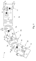
- FIG 1 a multi-axle steering system for a vehicle combination 1 is shown schematically using the example of a Gelenkomnibusses.
- the articulated bus consists of the vehicle cars 2a, 2b, 2c which are connected to each other by means of turntables 7a and 7b.
- kink angle sensors 5a, 5b are arranged. They serve to detect the bending angle ( ⁇ 1, ⁇ 2) between two vehicle carriages 2a, 2b or 2b, 2c.
- the bending angle sensor 5a detects the angle between the vehicle cars 2a and 2b.
- Each vehicle has a steering axle 6 for the wheel angle adjustment of the wheels 11 connected to the steering axles of a steerable axle.
- Each steering axle 6 is associated with a respective steering actuator 3a, 3b, 3c.
- the steering actuator 3a is formed as a ball-nut hydraulic steering known in the art.
- the steering actuators 3b and 3c are designed as a hydraulic-pneumatic rear-axle steering system.
- Each steering actuator 3a, 3b, 3c is assigned a control unit 8. The task of the control unit is to collect information about the current state of the vehicle and to assess and according to which a target specification for the individual steering actuator and thus the Radlenkwinkeln ⁇ 1a, ⁇ 1i, ⁇ 2a, ⁇ 2i associated with the respective steering axles 6 steered wheels 11 to determine.
- the signal connections 9 By means of the signal connections 9, the data transmission of the articulation angle information from the articulation angle sensors to the control units 8 is possible. Further, a signal connection line 10 is provided, which connects the control units with each other. This allows an exchange of information between the control units involved.
- the signal connections 9 and 10 are preferably designed as a bus system, for example as CAN, MOST or Flexray. However, other transfer techniques may be used, such as wireless connections.
- the current vehicle speed information, the axle load information, and the articulation angle and steering angle information derived from the buckling angle sensors 5a, 5b and the steering angle sensors 4 can be exchanged between the control units 8.
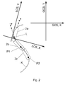
- FIG. 2 shows a vehicle combination with three vehicle carriages 2a, 2b, 2c which move relative to a first, global coordinate system GCS.
- the vehicle cars are coupled by means of joints.
- the first vehicle car 2a is the leading vehicle of the vehicle combination.
- the driver of the leading vehicle initiates a steering movement by means of a steering handle into the leading vehicle, which generates a direction of travel vector r at a reference point L when driving forwards.
- the reference point L represents a point in a local vehicle-vehicle-related coordinate system LCS and describes a trajectory K in a second, stationary global coordinate system GCS when the forward vehicle is traveling forwards.
- the wheel steering angle on a steerable axle of one of the following vehicle carriages is set as a function of the movement direction vector r at the reference point L with a time delay T. It is thus achieved that at least one of the follower points P1, P2 of the vehicle following the leading vehicle follows the trajectory K predetermined by a movement of the reference point L.
Landscapes
- Engineering & Computer Science (AREA)
- Chemical & Material Sciences (AREA)
- Combustion & Propulsion (AREA)
- Transportation (AREA)
- Mechanical Engineering (AREA)
- Steering Control In Accordance With Driving Conditions (AREA)
- Control Of Position, Course, Altitude, Or Attitude Of Moving Bodies (AREA)
Abstract
Description
Die Erfindung betrifft ein Verfahren zur Folgeführung eines Fahrzeugwagens in einem Fahrzeuggespann gemäß dem Oberbegriff des Anspruchs 1.
Die Erfindung betrifft auch eine Mehrachslenkungsanlage die nach dem erfindungsgemäßen Verfahren betrieben wird.The invention relates to a method for following a vehicle wagon in a vehicle combination according to the preamble of claim 1.
The invention also relates to a multi-axis steering system which is operated by the method according to the invention.
Die
Straßenfahrzeuge, beispielsweise ein Fahrzeuggespann, das aus mehreren Fahrzeugwagen besteht, beispielsweise aus einer Zugmaschine, einem Sattelschlepper oder einem Personenkraftwagen oder dem ersten Fahrzeugwagen eines ein- oder mehrgelenkigen Omnibusses und wenigstens einem weiteren Fahrzeugwagen, beispielsweise einem Anhänger oder Auflieger oder einem weiteren Wagenteil eines mehrgelenkigen Omnibusses, die mittels einer Einrichtung zur Koppelung, beispielsweise einem Drehteller, einer Anhängerkupplung oder einem Knickgelenk miteinander verbunden sind, besitzen keine Fahrzeugführung hinsichtlich des Nachlaufverhaltens nachfolgender Fahrzeugwagen in Bezug auf ein Führungsfahrzeug des Fahrzeuggespanns.Road vehicles, for example, a vehicle combination consisting of several vehicles, such as a tractor, a semi-trailer or a passenger car or the first vehicle of a single or multi-articulated bus and at least one other vehicle, such as a trailer or semitrailer or another car part of a multi-articulated bus , which are connected to each other by means of a coupling device, such as a turntable, a trailer hitch or an articulated joint, have no vehicle management with regard to the tracking behavior of subsequent vehicle car with respect to a leading vehicle of the vehicle combination.
Aus dem Stand der Technik sind zudem Lösungen zur Spurhaltung und Spurführung bekannt. Das in der Offenlegungsschrift
Des weiteren ist aus der
Der Erfindung liegt die Aufgabe zugrunde, ein Verfahren für die Folgeführung von Fahrzeugwagen in einem Fahrzeuggespann anzugeben, welches es ermöglicht, dass die einzelnen Fahrzeugwagen eines Fahrzeuggespanns der durch ein Führungsfahrzeug vorgegebenen Fahrbewegung während einer Vorwärtsfahrt besser nachfolgen können.The invention has for its object to provide a method for the follow-up of vehicle vehicles in a vehicle combination, which makes it possible that the individual vehicles of a vehicle combination can follow the predefined by a leader vehicle travel during forward travel better.
Des Weiteren liegt der Erfindung die Aufgabe zugrunde, ein zur Durchführung des erfindungsgemäßen Verfahrens geeignete Mehrachslenkungsanlage in einem Fahrzeuggespann anzugeben.Furthermore, the invention is based on the object, a for Implementation of the method according to the invention to provide suitable multi-axle steering system in a vehicle combination.
Die Aufgabe wird verfahrensgemäß mit den kennzeichnenden Merkmalen des Anspruchs 1 gelöst. Vorteilhafte Ausgestaltungen der Erfindung sind in den abhängigen Ansprüchen angegeben.
Die einrichtungsgemäße Lösung der Aufgabe wird mit den Merkmalen des Anspruchs 9 gelöst.The object is achieved according to the method with the characterizing features of claim 1. Advantageous embodiments of the invention are specified in the dependent claims.
The device according to the solution of the problem is solved with the features of
Erfindungsgemäß ist in einem Verfahren zur Führung eines Fahrzeuggespanns vorgesehen, dass nach Maßgabe eines die Bewegungsrichtung eines Bezugspunktes L beschreibenden Bewegungsrichtungsvektors (
Die Regel berücksichtigt dabei physikalisch messbare Größen wie beispielsweise die Fahrzeuggeschwindigkeit, Beschleunigungs- und Verzögerungswerte oder sonstige Größen zu Beschreibung des aktuellen fahrzeugdynamischen Zustands. In einer besonders einfachen Ausführungsform wird der Bezugspunkt L anhand der festgelegten geometrischen Größen des Führungsfahrzeuges, beispielsweise der Rad- und Achsabstände bestimmt.The rule takes into account physically measurable variables such as the vehicle speed, acceleration and deceleration values or other variables for describing the current vehicle dynamic state. In a particularly simple embodiment, the reference point L is determined based on the specified geometric sizes of the leading vehicle, such as the wheel and axle spacings.
Eine Weiterentwicklung sieht vor, den Bezugspunk L unter Verwendung von Koordinatendaten aus einer Einheit zur satellitengestützten Standortbestimmung, einem GPS System, welches an einem festen Ort des Fahrzeugwagens angeordnet ist, zu bestimmen. Zur Erhöhung der Genauigkeit der zeitabhängigen Weginformation und letztendlich des die Bewegungsrichtung beschreibenden Vektors (
Eine weitere Ausgestaltung der Erfindung sieht vor, dass die Bestimmung des Radlenkwinkels β zusätzlich in Abhängigkeit einer ersten oder zweiten Ableitung des Bewegungsrichtungsvektors (
Die vorteilhafte Wirkung bei Anwendung des erfindungsgemäßen Verfahrens wird beim Durchfahren einer kurvenartigen Fahrstrecke, insbesondere einer Fahrstrecke, welche aus auf einander folgende konvex und konkav- gebogenen und/oder dazwischen liegenden oder voran- oder nachgestellten geradlinigen Streckenabschnitten besteht, erreicht: Die Folgepunkte P1, P2, bewegen sich weitestgehend auf der Trajektorie K.The advantageous effect when using the method according to the invention is achieved when driving through a curved route, in particular a driving route, which consists of consecutive convexly and concavely curved and / or intermediate or leading or trailing rectilinear sections: The following points P1, P2 , move as far as possible on the trajectory K.
In einer weiteren, besonders vorteilhaften Ausgestaltung der Erfindung ist vorgesehen, dass eine variable Bestimmung des Wertes T in Abhängigkeit der momentanen Fahrgeschwindigkeit des Fahrzeuggespanns oder eines Fahrzeugwagens erfolgt. Der Bezugspunkt L kann dabei auch im Bereich eines Gelenkes liegen.In a further, particularly advantageous embodiment of the invention, it is provided that a variable determination of the value T takes place as a function of the instantaneous driving speed of the vehicle combination or of a vehicle vehicle. The reference point L can also be in the region of a joint.
In einer vorrichtungsgemäßen Ausgestaltung ist gemäß des Anspruchs 8 vorgesehen, eine Mehrachslenkungsanlage in einem aus mehreren Fahrzeugwagen bestehenden und mittels Gelenke verbundenen Fahrzeuggespann zur Folgeführung der Fahrzeugwagen nach dem erfindungsgemäßen Verfahren zu betreiben.In a device according to the invention, provision is made according to claim 8 to operate a multi-axle steering system in a vehicle combination consisting of a plurality of vehicle carriages and connected by joints for following the vehicle carriages by the method according to the invention.
Ist ein Fahrzeuggespann mit einer Mehrachslenkungsanlage ausgerüstet, die mit dem erfindungsgemäßen Verfahren betrieben wird, wird beim Durchfahren einer kurvenartigen Fahrstrecke, insbesondere einer Fahrstrecke, welche aus auf einander folgende konvex oder konkavgebogenen oder geradlinigen Streckenabschnitten besteht, der Raumbedarf des Fahrzeuggespanns zumindest drastisch reduziert und im Idealfall minimiert.
Durch das erfindungsgemäße Verfahren wird zusätzlich die Fahrsicherheit des Fahrzeuggespanns erhöht, da der Führer des Fahrzeuggespanns davon ausgehen kann, dass keiner der nachfolgenden Fahrzeugwagen die "Kurve schneidet" und damit Personen- und/oder Sachschäden vermieden werden können. Dies ist besonders relevant hinsichtlich der Tatsache, dass der durch die Rückspiegel des Führungsfahrzeugs observierbare Raum nachfolgende Fahrzeugwagen in Kurven unzureichend erfassen kann.If a vehicle combination equipped with a multi-axis steering system, which is operated by the method according to the invention, the space requirement of the vehicle combination is at least drastically reduced when driving through a curve-like route, in particular a route, which consists of consecutive convex or concave curved or rectilinear sections, and ideally minimized.
The method according to the invention additionally increases the driving safety of the vehicle combination, since the driver of the vehicle combination can assume that none of the following vehicle vehicles will "cut" the curve and thus avoid personal injury and / or property damage. This is especially relevant in terms of The fact that the space observable by the rearview mirrors of the leading vehicle can insufficiently detect subsequent vehicle carriages in curves.
Weitere Einzelheiten und Vorteile der Erfindung ergeben sich aus den nachfolgenden Figurenbeschreibungen und den beigefügten Zeichnungen.
Es zeigen
- Fig. 1 eine schematische Darstellung einer Mehrachslenkungsanlage in einem Fahrzeuggespann am Beispiel eines Mehrgelenkomnibusses.
- Fig. 2 eine schematische Darstellung zur Veranschaulichung des erfindungsgemäßen Verfahrens am Beispiel eines Mehrgelenkomnibusses.
Show it
- Fig. 1 is a schematic representation of a multi-axle steering system in a vehicle combination on the example of a multi-articulated bus.
- Fig. 2 is a schematic representation for illustrating the method according to the invention on the example of a multi-link bus.
Bezugszeichenliste
In Figur 1 ist schematisch eine Mehrachslenkungsanlage für ein Fahrzeuggespann 1 am Beispiel eines Gelenkomnibusses dargestellt. Der Gelenkomnibus besteht aus den Fahrzeugwagen 2a, 2b, 2c die mittels Drehtellern 7a und 7b miteinander verbunden sind. An den Knickgelenken 7a, 7b sind Knickwinkelsensoren 5a, 5b angeordnet. Sie dienen zur Erfassung des Knickwinkels (ω1, ω2) zwischen zwei Fahrzeugwagen 2a, 2b oder 2b, 2c. So erfasst der Knickwinkelsensor 5a den Winkel zwischen den Fahrzeugwagen 2a und 2b. Jeder Fahrzeugwagen weist eine Lenkachse 6 zur Radwinkelverstellung der mit den Lenkachsen verbunden Räder 11 einer lenkbaren Achse auf. Jeder Lenkachse 6 ist jeweils ein Lenkaktuator 3a, 3b, 3c zugeordnet. In diesem Beispiel ist der Lenkaktuator 3a als eine aus dem Stand der Technik bekannte Kugelmutter-Hydrolenkung ausgebildet. Die Lenkaktuatoren 3b und 3c sind als hydraulisch- pneumatisches Hinterachslenksystem ausgeführt. Jedem Lenkaktuator 3a, 3b, 3c ist eine Steuereinheit 8 zugeordnet. Aufgabe der Steuereinheit ist es, Informationen über den momentanen Fahrzeugzustand zu einzusammeln und zu bewerten und nach Maßgabe derer eine Sollvorgabe für die einzelnen Lenkaktuator und damit den Radlenkwinkeln β1a, β1i, β2a, β2i der mit den jeweiligen Lenkachsen 6 verbundenen gelenkten Rädern 11 zu ermitteln. Mittels den Signalverbindungen 9 ist die Datenübertragung der Knickwinkelinformation aus den Knickwinkelsensoren zur der Steuereinheiten 8 möglich. Ferner ist eine Signalverbindungsleitung 10 vorgesehen, die die Steuereinheiten untereinander verbindet. Dies ermöglicht einen Informationsaustausch der beteiligten Steuereinheiten untereinander. Die Signalverbindungen 9 und 10 sind bevorzugt als Bussystem ausgeführt, beispielsweise als CAN, MOST oder Flexray. Es können jedoch auch andere Überragungstechniken eingesetzt werden, z.B. drahtlose Verbindungen.In Figure 1, a multi-axle steering system for a vehicle combination 1 is shown schematically using the example of a Gelenkomnibusses. The articulated bus consists of the
So kann die momentane Fahrgeschwindigkeitsinformation, die Informationen über die Achslasten und die Knickwinkel- und Lenkwinkelinformation, die aus den Knickwinkelsensoren 5a, 5b und den Lenkwinkelsensoren 4 stammen, zwischen den Steuereinheiten 8 ausgetauscht werden.Thus, the current vehicle speed information, the axle load information, and the articulation angle and steering angle information derived from the
Anhand des im Folgenden erläuterten Verfahrens wird beispielhaft die erfindungsgemäße Lösung der Aufgabestellung beschrieben.
In der Figur 2 ist ein Fahrzeuggespann mit drei Fahrzeugwagen 2a, 2b, 2c dargestellt die sich relativ zu einem ersten, globalen Koordinatensystem GCS bewegen. Die Fahrzeugwagen sind mittels Gelenke verkoppelt. Der erste Fahrzeugwagen 2a ist dabei das Führungsfahrzeug des Fahrzeuggespanns. Der Fahrer des Führungsfahrzeuges leitet mittels einer Lenkhandhabe eine Lenkbewegung in das Führungsfahrzeug ein, die bei einer Vorwärtsfahrt einen Bewegungsrichtungsvektor r an einem Bezugspunkt L erzeugt. Der Bezugspunkt L stellt dabei einen Punkt in einem lokalen, fahrzeugwagenbezogenen Koordinatensystem LCS dar und beschreibt bei Vorwärtsfahrt des Führungsfahrzeuges eine Trajektorie K in einem zweiten, ortsfesten globalen Koordinatensystem GCS. Der Radlenkwinkel an einer lenkbaren Achse eines der nachfolgenden Fahrzeugwagen wird in Abhängigkeit des Bewegungsrichtungsvektors r am Bezugspunkt L mit einer Zeitverzögerung T gestellt. Damit wird erreicht, dass zumindest einer der Folgepunkte P1, P2 der dem Führungsfahrzeug folgenden Fahrzeugwagen der durch eine Bewegung des Bezugspunkt L vorgegebenen Trajektorie K folgt.Based on the method explained below, the inventive solution of the task is described by way of example.
FIG. 2 shows a vehicle combination with three
Claims (9)
dadurch gekennzeichnet, dass nach Maßgabe eines die Bewegungsrichtung eines Bezugspunktes (L) beschreibenden Bewegungsrichtungsvektors (
characterized in that in accordance with a direction of movement of a reference point (L) descriptive movement direction vector (
Applications Claiming Priority (1)
| Application Number | Priority Date | Filing Date | Title |
|---|---|---|---|
| DE200610018389 DE102006018389A1 (en) | 2006-04-20 | 2006-04-20 | Method for following a vehicle wagon in a vehicle combination |
Publications (2)
| Publication Number | Publication Date |
|---|---|
| EP1847442A2 true EP1847442A2 (en) | 2007-10-24 |
| EP1847442A3 EP1847442A3 (en) | 2009-09-02 |
Family
ID=38231101
Family Applications (1)
| Application Number | Title | Priority Date | Filing Date |
|---|---|---|---|
| EP07106005A Withdrawn EP1847442A3 (en) | 2006-04-20 | 2007-04-12 | Method for path guidance of single parts or an articulated vehicle |
Country Status (2)
| Country | Link |
|---|---|
| EP (1) | EP1847442A3 (en) |
| DE (1) | DE102006018389A1 (en) |
Cited By (10)
| Publication number | Priority date | Publication date | Assignee | Title |
|---|---|---|---|---|
| RU2518697C2 (en) * | 2010-02-24 | 2014-06-10 | Сандвик Майнинг Энд Констракшн Ой | Articulated vehicle and trailer for articulated vehicle |
| WO2015192986A1 (en) * | 2014-06-17 | 2015-12-23 | Robert Bosch Automotive Steering Gmbh | Method for assisting a driver in maneuvering a motor-vehicle combination |
| JP2019513625A (en) * | 2016-04-12 | 2019-05-30 | サウスウエスト ジャオトン ユニバーシティーSouthwest Jiaotong University | Steering control apparatus for trackless train and control method therefor |
| EP3932779A1 (en) * | 2020-07-03 | 2022-01-05 | Volvo Truck Corporation | A method for guiding a vehicle |
| CN114104104A (en) * | 2021-11-19 | 2022-03-01 | 中车南京浦镇车辆有限公司 | Steering control method for multi-grouping articulated vehicle |
| US20220111893A1 (en) * | 2020-10-14 | 2022-04-14 | HÜBNER GmbH & Co. KG | Steering control system of a multi-unit vehicle |
| WO2022183233A1 (en) | 2021-03-04 | 2022-09-09 | Ceres Gmbh | System for steering a trailer attached to a towing vehicle |
| US11447374B2 (en) | 2016-09-15 | 2022-09-20 | Terex Australia Pty Ltd | Crane counterweight and suspension |
| WO2022248204A1 (en) * | 2021-05-25 | 2022-12-01 | Volvo Truck Corporation | An adaptive path following algorithm for heavy-duty vehicles |
| US12049251B2 (en) | 2021-02-05 | 2024-07-30 | GM Global Technology Operations LLC | Trailer tracking control |
Families Citing this family (2)
| Publication number | Priority date | Publication date | Assignee | Title |
|---|---|---|---|---|
| DE102013007854A1 (en) * | 2013-05-08 | 2014-11-13 | Jungheinrich Aktiengesellschaft | Industrial truck for a tugger train |
| US9956909B2 (en) | 2013-11-18 | 2018-05-01 | Robert Bosch Gmbh | Vector-based driver assistance for towing vehicle |
Citations (4)
| Publication number | Priority date | Publication date | Assignee | Title |
|---|---|---|---|---|
| AT395401B (en) * | 1989-06-20 | 1992-12-28 | Mut Maschinen Umwelttechnik | Steering procedure for articulated road trains |
| DE19806655A1 (en) * | 1998-02-18 | 1999-08-26 | Owerfeldt | Electronic reversing aid for lorry with trailer |
| WO2004102297A1 (en) * | 2003-05-19 | 2004-11-25 | Daimlerchrysler Ag | Vehicle control system |
| DE102004009465A1 (en) * | 2004-02-27 | 2005-09-15 | Daimlerchrysler Ag | Control system for unit of traction vehicle and trailer has trailer co-ordination unit to generate trailer-specific actual data to reduce dangers when reversing |
Family Cites Families (4)
| Publication number | Priority date | Publication date | Assignee | Title |
|---|---|---|---|---|
| US5579228A (en) * | 1991-05-21 | 1996-11-26 | University Of Utah Research Foundation | Steering control system for trailers |
| DE19510208A1 (en) * | 1995-03-21 | 1996-09-26 | Zahnradfabrik Friedrichshafen | Multi-axle steering system for vehicles |
| DE10312513B4 (en) * | 2003-03-20 | 2008-09-04 | Daimler Ag | Lane assistance system in a vehicle |
| DE10316413B4 (en) * | 2003-04-10 | 2011-02-03 | Man Nutzfahrzeuge Ag | Method and device for tracking a vehicle, in particular a commercial vehicle |
-
2006
- 2006-04-20 DE DE200610018389 patent/DE102006018389A1/en not_active Withdrawn
-
2007
- 2007-04-12 EP EP07106005A patent/EP1847442A3/en not_active Withdrawn
Patent Citations (4)
| Publication number | Priority date | Publication date | Assignee | Title |
|---|---|---|---|---|
| AT395401B (en) * | 1989-06-20 | 1992-12-28 | Mut Maschinen Umwelttechnik | Steering procedure for articulated road trains |
| DE19806655A1 (en) * | 1998-02-18 | 1999-08-26 | Owerfeldt | Electronic reversing aid for lorry with trailer |
| WO2004102297A1 (en) * | 2003-05-19 | 2004-11-25 | Daimlerchrysler Ag | Vehicle control system |
| DE102004009465A1 (en) * | 2004-02-27 | 2005-09-15 | Daimlerchrysler Ag | Control system for unit of traction vehicle and trailer has trailer co-ordination unit to generate trailer-specific actual data to reduce dangers when reversing |
Cited By (20)
| Publication number | Priority date | Publication date | Assignee | Title |
|---|---|---|---|---|
| US8833505B2 (en) | 2010-02-24 | 2014-09-16 | Sandvik Mining And Construction Oy | Articulated transport equipment and trailer for articulated transport equipment |
| RU2518697C2 (en) * | 2010-02-24 | 2014-06-10 | Сандвик Майнинг Энд Констракшн Ой | Articulated vehicle and trailer for articulated vehicle |
| WO2015192986A1 (en) * | 2014-06-17 | 2015-12-23 | Robert Bosch Automotive Steering Gmbh | Method for assisting a driver in maneuvering a motor-vehicle combination |
| US9988085B2 (en) | 2014-06-17 | 2018-06-05 | Robert Bosch Automotive Steering Gmbh | Method for assisting a driver in maneuvering a motor-vehicle combination |
| AU2015276542B2 (en) * | 2014-06-17 | 2018-10-25 | Robert Bosch Automotive Steering Gmbh | Method for assisting a driver in maneuvering a motor-vehicle combination |
| JP2019513625A (en) * | 2016-04-12 | 2019-05-30 | サウスウエスト ジャオトン ユニバーシティーSouthwest Jiaotong University | Steering control apparatus for trackless train and control method therefor |
| EP3418158A4 (en) * | 2016-04-12 | 2019-06-12 | Southwest Jiaotong University | Steering control device for trackless train and control method therefor |
| US11110959B2 (en) | 2016-04-12 | 2021-09-07 | Southwest Jiaotong University | Steering control device for trackless train and control method therefor |
| US11447374B2 (en) | 2016-09-15 | 2022-09-20 | Terex Australia Pty Ltd | Crane counterweight and suspension |
| EP4140858A1 (en) * | 2020-07-03 | 2023-03-01 | Volvo Truck Corporation | A method for guiding a vehicle |
| EP3932779A1 (en) * | 2020-07-03 | 2022-01-05 | Volvo Truck Corporation | A method for guiding a vehicle |
| US11897541B2 (en) | 2020-07-03 | 2024-02-13 | Volvo Truck Corporation | Method for guiding a vehicle |
| US20220111893A1 (en) * | 2020-10-14 | 2022-04-14 | HÜBNER GmbH & Co. KG | Steering control system of a multi-unit vehicle |
| EP3984863A1 (en) * | 2020-10-14 | 2022-04-20 | Hübner GmbH & Co. KG | Steering control system for a multi-part vehicle |
| US11891117B2 (en) * | 2020-10-14 | 2024-02-06 | HÜBNER GmbH & Co. KG | Steering control system of a multi-unit vehicle |
| US12049251B2 (en) | 2021-02-05 | 2024-07-30 | GM Global Technology Operations LLC | Trailer tracking control |
| WO2022183233A1 (en) | 2021-03-04 | 2022-09-09 | Ceres Gmbh | System for steering a trailer attached to a towing vehicle |
| WO2022248204A1 (en) * | 2021-05-25 | 2022-12-01 | Volvo Truck Corporation | An adaptive path following algorithm for heavy-duty vehicles |
| CN114104104A (en) * | 2021-11-19 | 2022-03-01 | 中车南京浦镇车辆有限公司 | Steering control method for multi-grouping articulated vehicle |
| CN114104104B (en) * | 2021-11-19 | 2024-04-19 | 中车南京浦镇车辆有限公司 | Steering control method for multi-group articulated vehicle |
Also Published As
| Publication number | Publication date |
|---|---|
| EP1847442A3 (en) | 2009-09-02 |
| DE102006018389A1 (en) | 2007-10-25 |
Similar Documents
| Publication | Publication Date | Title |
|---|---|---|
| EP1847442A2 (en) | Method for path guidance of single parts or an articulated vehicle | |
| DE102008026652B4 (en) | Steering device for setting a wheel lock angle | |
| EP1847443A2 (en) | Multi-axle steering system | |
| EP3944999B1 (en) | Method and driver assistance system for determining a vehicle path of a commercial vehicle | |
| EP0970875A2 (en) | Steering system for vehicles | |
| DE102006037588B4 (en) | Method for the automatic or semi-automatic tracking-accurate multi-axle steering of a road vehicle and apparatus for carrying out the method | |
| EP1048506B1 (en) | System for measuring and controlling the lateral deviation of the path of following vehicles from the path of a leading vehicle | |
| EP3219581A1 (en) | Steering of a rear carriage of a multi-part wheeled land vehicle, as well as such a land vehicle with a corresponding steering system, and a method for steering the rear carriage of such a land vehicle, in particular of an articulated bus | |
| DE102017112290A1 (en) | DYNAMIC REAL-TIME SYSTEM FOR STABILITY CONTROL BY THE DRIVER | |
| DE102016212677A1 (en) | Method for changing the wheel position of wheels of at least one axle of a motor vehicle as a function of the driving operation and motor vehicle for carrying out the method | |
| DE102017209980A1 (en) | Control system for steering a towing vehicle with a trailer | |
| DE102013220921A1 (en) | Steering angle device for a motor vehicle | |
| DE102018207311A1 (en) | Method for operating a steer-by-wire steering system of a vehicle | |
| DE102020112822A1 (en) | Driver assistance system for automated driving of a vehicle, vehicle with the same and driver assistance method for automated driving of a vehicle | |
| DE102015206768A1 (en) | Control for trailer-rear-assistance system | |
| DE102016014325A1 (en) | Method for adapting a parking assistance system to a vehicle | |
| DE102014214141A1 (en) | Method and control device for determining an angle between longitudinal axes of a combination of vehicle segments | |
| DE102010021561A1 (en) | Method for vehicle steering with a vehicle steering device | |
| DE10018532A1 (en) | Arrangement for setting vehicle tracking enables tracking angle to be actively adjusted during travel; tracking setting is automatically adjusted towards toe-in for critical situations | |
| DE102012005832A1 (en) | Brake system for controlling the rearrangement of a trailer vehicle | |
| EP3707058B1 (en) | Method for steering a vehicle | |
| EP4339073A1 (en) | Safety system for vehicle lateral guidance for a steer-by-wire steering system of a motor vehicle, safety method and motor vehicle | |
| DE102017126087A1 (en) | Vehicle with a turntable arrangement and method for controlling the vehicle | |
| DE102010039130A1 (en) | Method for determining actual steering ratio at front wheels of two-lane motor car for performing automatic parking, involves determining correction factor for steering ratio using deviation between actual steering angle and given target | |
| DE102019204565A1 (en) | Method of maneuvering a vehicle |
Legal Events
| Date | Code | Title | Description |
|---|---|---|---|
| PUAI | Public reference made under article 153(3) epc to a published international application that has entered the european phase |
Free format text: ORIGINAL CODE: 0009012 |
|
| AK | Designated contracting states |
Kind code of ref document: A2 Designated state(s): AT BE BG CH CY CZ DE DK EE ES FI FR GB GR HU IE IS IT LI LT LU LV MC MT NL PL PT RO SE SI SK TR |
|
| AX | Request for extension of the european patent |
Extension state: AL BA HR MK YU |
|
| PUAL | Search report despatched |
Free format text: ORIGINAL CODE: 0009013 |
|
| AK | Designated contracting states |
Kind code of ref document: A3 Designated state(s): AT BE BG CH CY CZ DE DK EE ES FI FR GB GR HU IE IS IT LI LT LU LV MC MT NL PL PT RO SE SI SK TR |
|
| AX | Request for extension of the european patent |
Extension state: AL BA HR MK RS |
|
| STAA | Information on the status of an ep patent application or granted ep patent |
Free format text: STATUS: THE APPLICATION IS DEEMED TO BE WITHDRAWN |
|
| 18D | Application deemed to be withdrawn |
Effective date: 20091031 |