DE102021123788A1 - Motor vehicle bending beam - Google Patents
Motor vehicle bending beam Download PDFInfo
- Publication number
- DE102021123788A1 DE102021123788A1 DE102021123788.2A DE102021123788A DE102021123788A1 DE 102021123788 A1 DE102021123788 A1 DE 102021123788A1 DE 102021123788 A DE102021123788 A DE 102021123788A DE 102021123788 A1 DE102021123788 A1 DE 102021123788A1
- Authority
- DE
- Germany
- Prior art keywords
- reinforcement plate
- motor vehicle
- bending beam
- base body
- section
- Prior art date
- Legal status (The legal status is an assumption and is not a legal conclusion. Google has not performed a legal analysis and makes no representation as to the accuracy of the status listed.)
- Pending
Links
Images


Classifications
-
- B—PERFORMING OPERATIONS; TRANSPORTING
- B62—LAND VEHICLES FOR TRAVELLING OTHERWISE THAN ON RAILS
- B62D—MOTOR VEHICLES; TRAILERS
- B62D25/00—Superstructure or monocoque structure sub-units; Parts or details thereof not otherwise provided for
- B62D25/04—Door pillars ; windshield pillars
Abstract
Ein erfindungsgemäßer Kraftfahrzeug-Biegeträger weist einen Basiskörper 2 aus härtbarem Stahl und ein mit dem Basiskörper 2 gefügtes Verstärkungsblech 3 aus härtbarem Stahl auf. Der Basiskörper 2 und das Verstärkungsblech 3 sind gemeinsam umgeformt, wobei der Basiskörper 2 einen Längenabschnitt 4 aufweist, welcher zwei Schenkel 7 und einen die Schenkel 7 verbindenden Steg 8 besitzt. Das Verstärkungsblech 3 ist in dem Längenabschnitt 4 angeordnet und liegt mit zumindest einem schenkelseitigen Randabschnitt 10 an einem Schenkel 7 an. Erfindungsgemäß erstreckt sich der Randabschnitt 10 des Verstärkungsblechs 3 entlang einer im Schenkel 7 ausgebildeten Stufe 13. Durch diese Ausgestaltung wird der Formvorgang und die optionale Formhärtung verbessert.

Description
Die Erfindung betrifft einen Kraftfahrzeug-Biegeträger gemäß den Merkmalen im Oberbegriff von Anspruch 1 und ein Kraftfahrzeug mit einem solchen Kraftfahrzeug-Biegeträger.The invention relates to a motor vehicle bending beam according to the features in the preamble of
Kraftfahrzeug-Biegeträger der erfindungsgemäßen Art sind insbesondere B-Säulen oder Stoßstangen bzw. Stoßfängerquerträger, aber auch generell Biegeträger mit einem im Querschnitt hut- bzw. U- oder V-förmigen Längenabschnitt. Solche Biegeträger unterliegen höchsten Anforderungen an ihre Festigkeit und Biegesteifigkeit. Sie sollen zudem eine gute Crashperformance gewährleisten.Motor vehicle flexural beams of the type according to the invention are, in particular, B-pillars or bumpers or bumper cross members, but also generally flexural beams with a longitudinal section that is hat-shaped, U-shaped, or V-shaped in cross section. Such bending beams are subject to the highest demands on their strength and flexural rigidity. They should also ensure good crash performance.
Zur Herstellung der Kraftfahrzeug-Biegeträger werden höchstfeste Stähle verwendet, insbesondere martensitische Stähle, Mehrphasenstähle oder Mangan-Bor-Stähle. Für letztere zählt das Formhärten zum Stand der Technik. Formhärten ist ein Verfahren zum Warmumformen von Stahlblechen, welches auch als Presshärten bezeichnet wird. Beim Formhärten wird ein Blech aus einem Mangan-Bor-Stahl auf eine Temperatur oberhalb der spezifischen Austenitisierungstemperatur des Werkstoffs erwärmt, in ein Umformwerkzeug eingelegt und zum Formbauteil warmumgeformt, wobei es während der Formgebung abkühlt. Im Umformwerkzeug eingespannt werden die Biegeträger durch die Kühlung gehärtet.High-strength steels, in particular martensitic steels, multi-phase steels or manganese-boron steels, are used to produce the motor vehicle bending beams. For the latter, hot stamping is state-of-the-art. Form hardening is a process for hot forming steel sheets, which is also known as press hardening. During form hardening, a sheet of manganese-boron steel is heated to a temperature above the specific austenitization temperature of the material, placed in a forming tool and hot-formed into a shaped component, with it cooling down during forming. Clamped in the forming tool, the bending beams are hardened by cooling.
Bekannt ist es im Automobilbau auch, Biegeträger lokal durch ein oder mehrere Verstärkungsbleche zu verstärken. Ein solches Verstärkungsblech wird fachterminologisch Patch genannt. Ein Verfahren zum Herstellen von lokal verstärkten Blechumformteilen zählt durch die
Der Basiskörper und das Verstärkungsblech bestehen aus einem härtbaren Stahl. Das Verstärkungsblech und der Basiskörper sind miteinander stoffschlüssig gefügt. Zur Herstellung des Biegeträgers wird üblicherweise das Verstärkungsblech mit der den Basiskörper bildenden Grundplatine aus Stahlblech vorgefügt, beispielsweise punktgeschweißt. Anschließend werden die Grundplatine und das Verstärkungsblech gemeinsam warmgeformt und pressgehärtet und die dreidimensionale Form des Biegeträgers erzeugt.The base body and the reinforcement plate are made of hardenable steel. The reinforcement plate and the base body are bonded to one another. To produce the bending beam, the reinforcement plate is usually pre-joined to the base plate made of sheet steel, which forms the base body, for example spot-welded. The base plate and the reinforcement plate are then hot-formed and press-hardened together and the three-dimensional shape of the bending beam is produced.
Bei einem an der Außenseite des Grundkörpers angeordneten Verstärkungsblech kann es beim Umformen der beiden Teile zu einer Art Hinterschnitt am Übergang der seitlichen Randbereiche des Verstärkungsblechs und der Schenkel des Grundkörpers kommen. Dieser führt dazu, dass das Oberwerkzeug nicht vollflächig an den Bauteilen anliegt. Dieser kontaktlose Bereich kann sich beim Warmformen und Presshärten negativ auf die Härtung auswirken und führt beim Umformen insbesondere dazu, dass ein Radius zwischen den Schenkeln und einem sich an einen Schenkel anschließenden auswärts gerichteten Flansch nicht bzw. schwieriger ausformen lässt. Hierdurch wird die Funktionalität und Qualität des Kraftfahrzeug-Biegeträgers beeinflusst. Auch kann dies nachteilige Auswirkungen auf das Verformungsverhalten des Biegeträgers bei einem Anprallvorgang (Crash) haben. In the case of a reinforcement plate arranged on the outside of the base body, a type of undercut can occur at the transition between the lateral edge regions of the reinforcement plate and the legs of the base body when the two parts are deformed. This means that the upper tool does not lie flat against the components. This non-contact area can have a negative effect on the hardening during hot forming and press hardening and, during forming, leads in particular to the fact that a radius between the legs and an outwardly directed flange adjoining a leg cannot be formed or is more difficult to form. This influences the functionality and quality of the motor vehicle bending beam. This can also have disadvantageous effects on the deformation behavior of the bending beam in the event of an impact (crash).
Der Erfindung liegt ausgehend vom Stand der Technik die Aufgabe zugrunde, einen funktional und qualitativ verbesserten Kraftfahrzeug-Biegeträger mit guter Crashperformance aufzuzeigen.Proceeding from the prior art, the invention is based on the object of demonstrating a functionally and qualitatively improved motor vehicle bending beam with good crash performance.
Die Lösung dieser Aufgabe besteht nach der Erfindung in einem Kraftfahrzeug-Biegeträger gemäß den Merkmalen von Anspruch 1.According to the invention, this object is achieved in a motor vehicle bending beam according to the features of
Vorteilhafte Ausgestaltungen des erfindungsgemäßen Kraftfahrzeug-Biegeträgers sind Gegenstand der abhängigen Ansprüche.Advantageous configurations of the motor vehicle bending beam according to the invention are the subject matter of the dependent claims.
Ausgestaltungen, Modifikationen von Merkmalen des Kraftfahrzeug-Biegeträgers, die einzeln oder in Kombination den Biegeträger funktional und technologisch vorteilhaft ausgestalten, ergeben sich auch aus der Beschreibung und den beigefügten Zeichnungen.Configurations, modifications of features of the motor vehicle bending beam, which individually or in combination make the bending beam functionally and technologically advantageous, also result from the description and the attached drawings.
Bei einem erfindungsgemäßen Kraftfahrzeug-Biegeträger handelt es sich insbesondere um eine Fahrzeugsäule, insbesondere um eine B-Säule oder um einen Bumper bzw. Stoßfängerquerträger. Der Kraftfahrzeug-Biegeträger kann auch Bestandteil eines Türringsystems eines Kraftfahrzeugs sein. Bei einem Kraftfahrzeug-Türring können biegerelevante Abschnitte in Fahrzeuglängsachse, Fahrzeugquerachse und/oder Fahrzeughochachse durch erfindungsgemäße Biegeträger gebildet sein. Der Türring kann einstückig ausgeführt sein, wobei biegerelevante Abschnitte durch einen erfindungsgemäß ausgestalteten Biegeträger gebildet sind.A motor vehicle bending beam according to the invention is in particular a vehicle pillar, in particular a B pillar or a bumper or bumper cross member. The motor vehicle bending beam can also be part of a door ring system of a motor vehicle. In a motor vehicle door ring, bending-relevant sections in the vehicle longitudinal axis, vehicle transverse axis and/or vehicle vertical axis can be formed by bending beams according to the invention. The door ring can be designed in one piece, with bending-relevant sections being formed by a bending beam designed according to the invention.
Der Kraftfahrzeug-Biegeträger weist einen Basiskörper auf, der lokal durch ein Verstärkungsblech verstärkt ist. Der Basiskörper und das Verstärkungsblech bestehen aus einem härtbaren Warmformstahl oder aus hochfestem Kaltformstahl. Basiskörper und Verstärkungsblech können aus dem gleich Stahl bzw. Stahllegierung bestehen. Die Stähle von Basiskörper und Verstärkungsblech können aber auch voneinander verschieden sein. Die Ausgangsplatinen für den Basiskörper und das Verstärkungsblech sind anfangs eben. Das ebene Verstärkungsblech wird an der Ausgangsplatine fixiert, beispielsweise mittels Punktschweißen, und zwar lokal an einer Stelle, in welcher es beim fertigen Biegeträger seine Verstärkungsaufgabe übernimmt. Die Ausgangsplatine und das Verstärkungsblech werden anschließend gemeinsam in einem Pressenwerkzeug geformt und gegebenenfalls pressgehärtet. Nach dem Umformen und/oder Formhärten kann ein Endfügen des Verstärkungsblechs am Basiskörper erfolgen. Auch dies erfolgt vorzugsweise schweißtechnisch.The motor vehicle bending beam has a base body that is locally reinforced by a reinforcement plate. The base body and the reinforcement plate consist of hardenable hot-form steel or high-strength cold-form steel. Base body and reinforcement plate can consist of the same steel or steel alloy. However, the steels of the base body and reinforcement plate can also be different from one another. The starting boards for the base body and the reinforcement plate are initially flat. The flat reinforcement plate is fixed to the starting board, for example by means of spot welding, specifically locally at a point in which it takes over its task of reinforcement in the finished bending beam. The The starting blank and the reinforcement sheet are then formed together in a press tool and, if necessary, press-hardened. After the forming and/or form hardening, the reinforcing sheet metal can be finally joined to the base body. This is also preferably done by welding.
Der Basiskörper des Kraftfahrzeug-Biegeträgers weist einen Längenabschnitt auf mit einem im Querschnitt hut-, U- oder V-förmigen Profil. Der Längenabschnitt besitzt zwei Schenkel und einen die Schenkel verbindenden Steg. Das Verstärkungsblech ist in dem Längenabschnitt angeordnet und konform zur Querschnittskonfiguration des Längenabschnitts des Verstärkungsblechs geformt. Bezogen auf die Einbaulage des Kraftfahrzeug-Biegeträgers in einem Kraftfahrzeug ist das Verstärkungsblech an der Außenseite des Biegeträgers gefügt. Hierbei liegt das Verstärkungsblech mit zumindest einem schenkelseitigen Randabschnitt an einem Schenkel an. Insbesondere übergreift das Verstärkungsblech den Basiskörper im Längenabschnitt. Entsprechend ist auch das Verstärkungsblech im Querschnitt hut- bzw. U- oder V-förmig profiliert. Das Verstärkungsblech weist in dieser Konfiguration einen Rücken auf, der vollflächig am Steg anliegt. Jeweils randseitig schließt sich an den Rücken des Verstärkungsblechs ein schenkelseitiger Randabschnitt an.The base body of the motor vehicle bending beam has a longitudinal section with a profile that is hat-shaped, U-shaped or V-shaped in cross section. The longitudinal section has two legs and a web connecting the legs. The reinforcement panel is disposed in the length and shaped to conform to the cross-sectional configuration of the length of reinforcement panel. Based on the installation position of the motor vehicle bending beam in a motor vehicle, the reinforcement plate is joined to the outside of the bending beam. In this case, the reinforcement plate rests against a leg with at least one edge section on the side of the leg. In particular, the reinforcement plate overlaps the base body in the longitudinal section. Correspondingly, the reinforcement plate is profiled in a hat, U or V shape in cross section. In this configuration, the reinforcement plate has a back which bears against the web over its entire surface. An edge section on the side of the leg adjoins the back of the reinforcement plate on each edge.
Erfindungsgemäß erstreckt sich zumindest ein Randabschnitt entlang einer Stufe, die in dem Schenkel ausgebildet ist, an welchem der Randabschnitt anliegt.According to the invention, at least one edge section extends along a step formed in the leg against which the edge section rests.
Bevorzugt ist in jedem Schenkel eine sich in Längsrichtung des Längenabschnitts erstreckende Stufe vorgesehen, an der entlang sich jeweils der zugehörige Randabschnitt erstreckt.A step extending in the longitudinal direction of the longitudinal section is preferably provided in each leg, along which the respective edge section extends.
Die erfindungsgemäße Lösung schafft Abhilfe hinsichtlich des Hinterschnittproblems, welches am Übergang zwischen dem Ende des Verstärkungsblechs entlang des Randabschnitts und dem Basiskörper auftritt. Der erfindungsgemäße Kraftfahrzeug-Biegeträger ist funktional und qualitativ verbessert und weist eine vorteilhafte Crashperformance auf.The solution according to the invention provides a remedy with regard to the undercut problem, which occurs at the transition between the end of the reinforcement plate along the edge section and the base body. The motor vehicle bending beam according to the invention is functionally and qualitatively improved and has an advantageous crash performance.
Das Außenwerkzeug liegt beim Umformvorgang in flächigem Kontakt am Verstärkungsblech und dem sich an die Stufe anschließenden unteren Schenkelabschnitt an. Hierdurch können die Umformkräfte gleichmäßig wirken. Die Formgebung wird verbessert ebenso wie im Falle des Presshärtens der Härtevorgang, der wesentlich effizienter und gleichmäßiger erfolgt. Hinterschnitte werden vermieden.During the forming process, the outer tool is in planar contact with the reinforcement plate and the lower leg section adjoining the step. This allows the forming forces to act evenly. The shaping is improved, as is the hardening process in the case of press hardening, which is much more efficient and uniform. Undercuts are avoided.
Der Basiskörper und das Verstärkungsblech besitzen eine Zugfestigkeit Rm von größer oder gleich (≥) 1.000 MPa. Der Basiskörper und das Verstärkungsblech können aus einem härtbaren Stahl, insbesondere einem Mangan-Bor-legierten Warmformstahl bestehen. Der Basiskörper und das Verstärkungsblech können auch ein ultrahochfester Kaltformstahl sein.The base body and the reinforcement plate have a tensile strength Rm greater than or equal to (≥) 1,000 MPa. The base body and the reinforcement plate can consist of a hardenable steel, in particular a manganese-boron-alloyed hot-forming steel. The base body and the reinforcement plate can also be an ultra-high-strength cold-forming steel.
Die Zugfestigkeit des Kraftfahrzeug-Biegeträgers beträgt größer oder gleich (≥) 1.000 MPa.The tensile strength of the automotive flexure is greater than or equal to (≥) 1,000 MPa.
Eine besonders vorteilhafte Ausführungsform sieht vor, dass die Ausgangsplatine und das Verstärkungsblech aus härtbarem Stahl bestehen und gemeinsam in einem Pressenwerkzeug warmgeformt und pressgehärtet werden. Die Bauteile werden einer Formhärtung im Pressenwerkzeug unterzogen.A particularly advantageous embodiment provides that the starting blank and the reinforcement sheet are made of hardenable steel and are hot-formed and press-hardened together in a press tool. The components are subjected to form hardening in the press tool.
Die erfindungsgemäß vorgesehene Stufe bzw. die erfindungsgemäß vorgesehenen Stufen werden beim Formvorgang erzeugt. Die Stufen werden gleichzeitig mit dem Warmformen oder dem Kaltformen erzeugt, also bevorzugt in der gleichen Umformstufe.The step or steps provided according to the invention are produced during the molding process. The steps are produced simultaneously with the hot forming or the cold forming, i.e. preferably in the same forming step.
Das Verstärkungsblech schließt am Randabschnitt entlang der Stufe bündig mit der Außenfläche der Stufe ab. Der Übergang zwischen der Außenfläche des Verstärkungsblechs und der benachbarten Außenfläche des Basiskörpers ist vorsprunglos.The reinforcement plate is flush with the outer surface of the step at the edge portion along the step. The transition between the outer surface of the reinforcement plate and the adjacent outer surface of the base body is without projections.
Die Stufe weist eine Stufenhöhe auf, welcher größer oder gleich (≥) der Dicke des Verstärkungsblechs bemessen ist.The step has a step height that is greater than or equal to (≥) the thickness of the reinforcement plate.
Wenn die Stufenhöhe größer ist als die Dicke des Verstärkungsblechs, steht die Außenfläche des sich von der Stufe abwärts erstreckenden Schenkelabschnitts gegenüber der Außenfläche des Verstärkungsblechs vor. Dies kann bauteilspezifisch vorteilhaft sein.When the step height is greater than the thickness of the reinforcement panel, the outer surface of the leg portion extending downward from the step projects from the outer surface of the reinforcement panel. This can be advantageous for specific components.
Das Verstärkungsblech besitzt eine in Längserstreckung des Basiskörpers bzw. des Längenabschnitts sich erstreckende Länge. Die Länge des Verstärkungsblechs erstreckt sich vorzugsweise über mindestens 30 % der Länge des Längenabschnitts.The reinforcing plate has a length that extends in the longitudinal extension of the base body or of the longitudinal section. The length of the reinforcement plate preferably extends over at least 30% of the length of the length section.
Es ist im Rahmen der Erfindung auch möglich, mehrere Verstärkungsbleche voneinander beabstandet anzuordnen, wobei diese bevorzugt in Summe eine Länge von mindestens 30 % aufweisen. Dies kann beispielsweise im Bereich der Scharnieranbindungen bei B-Säulen und A-Säulen als Biegeträger der Fall sein.It is also possible within the scope of the invention to arrange a plurality of reinforcement plates at a distance from one another, these preferably having a total length of at least 30%. This can be the case, for example, in the area of the hinge connections for B-pillars and A-pillars as bending beams.
Der Randabschnitt des Verstärkungsblechs besitzt eine Länge und eine Breite und der Schenkel eines Längenabschnitts besitzt eine Schenkelbreite. Ein Aspekt der Erfindung sieht vor, dass die Breite des Randabschnitts in bzw. über eine Teillänge des Randabschnitts wenigstens 50 % der Schenkelbreite beträgt. Das Verstärkungsblech erstreckt sich über einen Teil seiner Länge im Querschnitt in bzw. über die äußeren Schenkel, und zwar wenigstens bis zur halben Schenkelbreite.The edge portion of the reinforcement panel has a length and a width and the leg of a length portion has a leg width. One aspect of the invention provides that the width of the edge section in or over a partial length of the edge section is at least 50% of the leg width. The reinforcement plate extends over part of its length in cross-section into or over the outer legs, namely at least up to half the width of the leg.
Der Randabschnitt weist einen Längsstoß auf. Der Längsstoß bildet die Außenkante des Randabschnitts. Der Längsstoß ist mit einem Abstand zur Stufe im Schenkel angeordnet, wobei der Abstand zwischen 0,5 mm und 12 mm, insbesondere zwischen 3,0 mm und 8,0 mm bemessen ist.The edge section has a longitudinal joint. The longitudinal joint forms the outer edge of the edge section. The longitudinal joint is arranged at a distance from the step in the leg, the distance being between 0.5 mm and 12 mm, in particular between 3.0 mm and 8.0 mm.
Ausgehend von der Stufe erstreckt sich ein unterer Schenkelabschnitt, der in einen auswärts gerichteten Flansch übergeht. Insbesondere geht der untere Schenkelabschnitt über einen Radius in den äußeren Flansch über.A lower leg portion extends from the step and transitions into an outwardly directed flange. In particular, the lower leg section transitions into the outer flange via a radius.
Vorzugsweise weisen die Schenkel bezogen auf eine Vertikale einen Öffnungswinkel von 2° bis 10° auf, bevorzugt beträgt der Öffnungswinkel 3° bis 5°. Der Öffnungswinkel ist gemessen zwischen einer Vertikalen und der Innenseite des Schenkels, und zwar sowohl zum oberen Schenkelabschnitt oberhalb der Stufe als auch zum unteren Schenkelabschnitt unterhalb der Stufe.The legs preferably have an opening angle of 2° to 10° with respect to a vertical, preferably the opening angle is 3° to 5°. The opening angle is measured between a vertical and the inside of the leg, both to the upper leg section above the step and to the lower leg section below the step.
Die Stufe in einem Schenkel erstreckt sich insbesondere über die Länge des Randabschnitts eines Verstärkungsblechs. Bei einem Biegeträger in Form einer B-Säule sind folglich die in z-Achse gemessene Länge der Stufe und die Länge des Randabschnitts gleich.In particular, the step in a leg extends over the length of the edge section of a reinforcement plate. In the case of a bending beam in the form of a B-pillar, the length of the step measured in the z-axis and the length of the edge section are therefore the same.
Eine die Erfindung weiterbildende Ausführungsform sieht vor, dass die Stufe länger ist als die Länge des Verstärkungsblechs. Die Stufe wird so zu einer Steifigkeitserhöhung des Längenabschnitts und des Biegeträgers insgesamt ausgestaltet und kann sich bis in jeweils endseitig vorgesehene Anbindungsabschnitte des Biegeträgers erstrecken, die sich an den Längenabschnitt anschließen.An embodiment developing the invention provides that the step is longer than the length of the reinforcement plate. The step is designed to increase the rigidity of the longitudinal section and the bending beam overall and can extend into the connection sections of the bending beam that are provided at the ends and adjoin the longitudinal section.
Der Basiskörper und das Verstärkungsblech besitzen eine Zugfestigkeit Rm von größer oder gleich (≥) 1.000 MPa. Der Biegeträger, insbesondere der Basiskörper, und das Verstärkungsblech weisen eine vorwiegend martensitische und/oder bainitische Gefügestruktur auf. Durch die erfindungsgemäße Ausgestaltung wird eine gleichmäßige Zugfestigkeitsverteilung erreicht. Insbesondere weist der Basiskörper im Bereich der Stufe, den Schenkeln und dem Steg eine Zugfestigkeit Rm auf, welche um höchstens 150 MPa variiert. Dieser technische Effekt ergibt sich aus der erfindungsgemäß vorgesehenen Stufe und der dadurch bewirkten Hinterschnittvermeidung.The base body and the reinforcement plate have a tensile strength Rm greater than or equal to (≥) 1,000 MPa. The bending beam, in particular the base body, and the reinforcement plate have a predominantly martensitic and/or bainitic microstructure. A uniform distribution of tensile strength is achieved by the configuration according to the invention. In particular, the base body has a tensile strength Rm in the area of the step, the legs and the web, which varies by at most 150 MPa. This technical effect results from the step provided according to the invention and the resulting avoidance of an undercut.
Ein den Kraftfahrzeug-Biegeträger insgesamt qualitativ verbessernder Ausgestaltung sieht vor, dass zwischen dem Basiskörper und dem Verstärkungsblech eine Schicht vorgesehen ist. Diese Schicht ist insbesondere auf Aluminium-Silicium-Basis gebildet. Es handelt sich um eine Legierungsschicht aus dem Stahl des Basiskörpers und des Verstärkungsblechs und einem Beschichtungswerkstoff. Dieser besteht aus Aluminium-Silicium. Die Schicht wirkt adhäsiv und verbessert die Fügung zwischen Verstärkungsblech und Basiskörper. Insbesondere wirkt die Schicht korrosionshemmend und wirkt einer Spalt- und/oder Kontaktkorrosion entgegen.A design that improves the overall quality of the motor vehicle bending beam provides that a layer is provided between the base body and the reinforcement plate. This layer is formed in particular on an aluminium-silicon basis. It is an alloy layer made of the steel of the base body and the reinforcement plate and a coating material. This consists of aluminium-silicon. The layer has an adhesive effect and improves the joint between the reinforcement plate and the base body. In particular, the layer has a corrosion-inhibiting effect and counteracts crevice and/or contact corrosion.
Besonders vorteilhaft ist der gesamte Kraftfahrzeug-Biegeträger, also der Basiskörper und das bzw. die Verstärkungsbleche, mit einer Beschichtung versehen, welche insbesondere auf Aluminium-Silicium-Basis besteht.The entire motor vehicle bending beam, that is to say the base body and the reinforcement plate(s), is particularly advantageously provided with a coating which is based in particular on aluminium-silicon.
Bei einem Kraftfahrzeug mit einem erfindungsgemäßen Kraftfahrzeug-Biegeträger bildet der Biegeträger bevorzugt die B-Säule. Die B-Säule erstreckt sich zwischen einem Fahrzeugschweller und einem Dachrahmen. Bei einer vorteilhaften Ausführungsform ist das Verstärkungsblech so ausgestaltet, dass es im Einbauzustand im Fahrzeug sich nach unten erstreckt, und zwar so weit, dass es den Fahrzeugschweller wenigstens teilweise bzw. bereichsweise überlappt.In a motor vehicle with a motor vehicle bending beam according to the invention, the bending beam preferably forms the B-pillar. The B-pillar extends between a vehicle rocker panel and a roof rail. In an advantageous embodiment, the reinforcement plate is designed in such a way that when it is installed in the vehicle it extends downwards to such an extent that it at least partially or in certain areas overlaps the vehicle rocker panel.
Die Erfindung ist nachfolgend anhand von Zeichnungen näher beschrieben. Es zeigen:
-
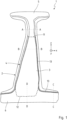
1 einen erfindungsgemäßen Kraftfahrzeug-Biegeträger in Form einer B-Säule in einer Ansicht; -
2 einen Schnitt durch dieDarstellung der 1 entlang der Linie A-A; -
3 einen Schnitt durch dieDarstellung der 1 entlang der Linie B-B; -
4 einen Schnitt durch dieDarstellung der 1 entlang der Linie C-C; -
5 einen Schnitt durch dieDarstellung der 1 entlang der Linie D-D; -
6 eine weitere Ausführungsform eines Kraftfahrzeug-Biegeträgers in Form einer B-Säule in einer Ansicht; -
7 einen Schnitt durch dieDarstellung der 6 entlang der Linie A-A; -
8 einen Schnitt durch dieDarstellung der 6 entlang der Linie B-B; -
9 einen Schnitt durch dieDarstellung der 6 entlang der Linie C-C; -
10 einen Schnitt durch einen Kraftfahrzeug-Biegeträger entsprechend derDarstellung von 6 entlang der Linie B-B mit einer Variante der Stufenkonfiguration; -
11 eine weitere Ausführungsform eines Kraftfahrzeug-Biegeträgers in Form einer B-Säule; -
12 eine weitere Ausführungsform eines Kraftfahrzeug-Biegeträgers in Form einer B-Säule; -
13 einen Schnitt durch dieDarstellung der 12 entlang der Linie A-A; -
14 einen Schnitt durch dieDarstellung der 12 entlang der Linie B-B und -
15 technisch schematisiert eine Seitenansicht auf einen Kraftfahrzeug-Biegeträger.
-
1 a motor vehicle bending beam according to the invention in the form of a B-pillar in a view; -
2 a cut through the representation of1 along line AA; -
3 a cut through the representation of1 along line BB; -
4 a cut through the representation of1 along line CC; -
5 a cut through the representation of1 along line DD; -
6 another embodiment of a motor vehicle bending beam in the form of a B-pillar in a view; -
7 a cut through the representation of6 along line AA; -
8th a cut through the representation of6 along line BB; -
9 a cut through the representation of6 along line CC; -
10 a section through a motor vehicle bending beam according to the representation of6 along line BB with a variant of the step configuration; -
11 a further embodiment of a motor vehicle bending beam in the form of a B-pillar; -
12 a further embodiment of a motor vehicle bending beam in the form of a B-pillar; -
13 a cut through the representation of12 along line AA; -
14 a cut through the representation of12 along line BB and -
15 technically schematized side view of a motor vehicle bending beam.
In den
In den
Begriffe die quer und längs, oben und unten, horizontal und vertikal oder Längsrichtung, längsgerichtet und Querrichtung, quergerichtet sowie randseitig, oberseitig oder unterseitig beziehen sich auf die Einbaulage des jeweiligen Kraftfahrzeug-Biegeträgers im Kraftfahrzeug.Terms such as transverse and longitudinal, above and below, horizontal and vertical or longitudinal direction, longitudinal and transverse direction, transverse and edge, top or bottom refer to the installation position of the respective motor vehicle bending beam in the motor vehicle.
In den
Die B-Säule 1 weist einen Basiskörper 2 aus härtbarem oder gehärteten Stahl sowie ein mit dem Basiskörper 2 gefügtes Verstärkungsblech 3 aus härtbarem oder gehärteten Stahl auf. Der Basiskörper 2 und das Verstärkungsblech 3 sind gemeinsam umgeformt, insbesondere formgehärtet, in einem Umform- bzw. Pressenwerkzeug warmgeformt und pressgehärtet.The B-
Der Basiskörper 2 weist einen sich in z-Richtung (Fahrzeughochachse) erstreckenden Längenabschnitt 4 auf. An diesen schließt sich in Bildebene ein oberer Kopfabschnitt 5 und ein unterer Fußabschnitt 6 an. Der Kopfabschnitt 5 dient zur Anbindung der B-Säule 1 an einen Dachrahmen. Der Fußabschnitt 6 dient zur Anbindung der B-Säule 1 an einen Fahrzeugschweller.The
Der Basiskörper 2 weist im Längenabschnitt 4 einen hut- bzw. U-förmigen Querschnitt auf mit zwei seitlichen Schenkeln 7 und einen die Schenkel 7 verbindenden Steg 8. Das Verstärkungsblech 3 ist in dem Längenabschnitt 4 angeordnet. Das Verstärkungsblech 3 ist stoffschlüssig mit dem Basiskörper 2 gefügt und befindet sich an der Außenseite des Basiskörpers 2. Das Verstärkungsblech 3 ist ebenfalls im Querschnitt hut- bzw. U-förmig konfiguriert und weist einen Rücken 9 auf, an welchen sich beidseitig ein schenkelseitiger Randabschnitt 10 anschließt. Mit den schenkelseitigen Randabschnitten 10 liegt das Verstärkungsblech 3 jeweils an einem Schenkel 7 des Längenabschnitts 4 des Basiskörpers 2 an.The
Der Rücken 9 liegt an der Außenfläche des Stegs 8 an. Das Verstärkungsblech 3 weist eine Länge LV auf und erstreckt sich über mindestens 30 % der Länge LL des Längenabschnitts 4. Die Kopfkante 11 und die Fußkante 12 des Verstärkungsblechs 3 sind in den
Die Randabschnitte 10 erstrecken sich jeweils entlang einer in den Schenkeln 7 ausgebildeten Stufe 13. Dies zeigen insbesondere die Darstellungen der
Die
Die
Eine Stufe 13 erstreckt sich jeweils bis in den sich nach links und rechts vom Längenabschnitt 4 erstreckenden unteren Fußabschnitt 6 der B-Säule 1 (vgl.
Die
Die
In den
Die
Der Öffnungswinkel α liegt in einem Bereich zwischen 2° und 10° und insbesondere zwischen 3° und 5°.The opening angle α is in a range between 2° and 10° and in particular between 3° and 5°.
Die Darstellung der
Die
Ein Randabschnitt 10 des Verstärkungsblechs 3 besitzt eine Länge LR und eine Breite BR. Der bzw. die Schenkel 7 besitzen eine Schenkelbreite SB. Die Breite BR des Randabschnitts 10 beträgt zumindest über einen Teil seiner Länge wenigstens 30 % der Schenkelbreite SB. Insbesondere in einer mittleren Teillänge TL ist die Breite BR des Randabschnitts 10 größer als die Hälfte der Schenkelbreite SB. Jeweils zum oberen oder unteren Ende eines Verstärkungsblechs 3 kann die Breite BR des Randabschnitts 10 abnehmen und zum Ende hin auslaufen.An
Die
Die
Ein Randabschnitt 10 weist an seinem freien Ende einen Längsstoß 19 auf. Der Längsstoß 19 ist mit Abstand a zur benachbarten Stufe 13 angeordnet. Der Abstand a beträgt zwischen 0,5 mm und 12 mm. Insbesondere beträgt der Abstand a zwischen 5,0 mm und 8,0 mm.An
Bei allen Ausführungsformen der B-Säule 1 weist der Basiskörper 2 und das Verstärkungsblech 3 eine Zugfestigkeit Rm von größer oder gleich ≥ 1.000 MPa auf und besitzt eine vorliegend martensitische und/oder bainitische Gefügestruktur. Der Festigkeitsverlauf ist über die Bauteile gleichmäßig. Im Bereich der Stufe 13 sowie den Schenkeln 7 und dem Steg 8 besitzt der Basiskörper 2 eine Zugfestigkeit Rm, die gleichmäßig hoch ist und um maximal 150 MPa variiert.In all embodiments of the B-
Nicht in den Zeichnungen dargestellt aber vorteilhaft ist, wenn zwischen dem Basiskörper 2 und dem Verstärkungsblech 3 eine Schicht vorgesehen ist. Hierbei handelt es sich um eine Legierungsschicht auf Aluminium-Silicium-Basis, die mit dem Stahl vom Basiskörper 2 und/oder Verstärkungsblech 3 legiert ist.Not shown in the drawings but is advantageous if a layer is provided between the
BezugszeichenlisteReference List
- 11
- B-SäuleB pillar
- 22
- Basiskörperbase body
- 33
- Verstärkungsblechreinforcement plate
- 44
- Längenabschnittlength section
- 55
- Kopfabschnitthead section
- 66
- Fußabschnittfoot section
- 77
- Schenkelleg
- 88th
- Stegweb
- 99
- RückenMove
- 1010
- Randabschnittedge section
- 1111
- Kopfkante v. 3head edge v. 3
- 1212
- Fußkante v. 3foot edge v. 3
- 1313
- StufeStep
- 1414
- Übergangcrossing
- 1515
- Flanschflange
- 1616
- unterer Schenkelabschnittlower leg section
- 1717
- oberer Schenkelabschnittupper leg section
- 1818
- Schwellerabschnittsill section
- 1919
- Längsstoß longitudinal joint
- aa
- AbstandDistance
- di.e
- Dicke v. 3thickness of 3
- ss
- Stufenhöhestep height
- BRBR
- Breite v. 10width from 10
- LLLL
- Länge v. 4length from 4
- LRLR
- Länge v. 10length from 10
- LSLS
- Länge v. 13length from 13
- LVLV
- Länge v. 3length from 3
- Rmrm
- Zugfestigkeittensile strenght
- SBSB
- Schenkelbreiteleg width
- TLtsp
- Teillänge v. 10part length v. 10
- αa
- Öffnungswinkelopening angle
ZITATE ENTHALTEN IN DER BESCHREIBUNGQUOTES INCLUDED IN DESCRIPTION
Diese Liste der vom Anmelder aufgeführten Dokumente wurde automatisiert erzeugt und ist ausschließlich zur besseren Information des Lesers aufgenommen. Die Liste ist nicht Bestandteil der deutschen Patent- bzw. Gebrauchsmusteranmeldung. Das DPMA übernimmt keinerlei Haftung für etwaige Fehler oder Auslassungen.This list of documents cited by the applicant was generated automatically and is included solely for the better information of the reader. The list is not part of the German patent or utility model application. The DPMA assumes no liability for any errors or omissions.
Zitierte PatentliteraturPatent Literature Cited
- DE 10049660 B4 [0004]DE 10049660 B4 [0004]
Claims (13)
Priority Applications (1)
| Application Number | Priority Date | Filing Date | Title |
|---|---|---|---|
| DE102021123788.2A DE102021123788A1 (en) | 2021-09-14 | 2021-09-14 | Motor vehicle bending beam |
Applications Claiming Priority (1)
| Application Number | Priority Date | Filing Date | Title |
|---|---|---|---|
| DE102021123788.2A DE102021123788A1 (en) | 2021-09-14 | 2021-09-14 | Motor vehicle bending beam |
Publications (1)
| Publication Number | Publication Date |
|---|---|
| DE102021123788A1 true DE102021123788A1 (en) | 2023-03-16 |
Family
ID=85284852
Family Applications (1)
| Application Number | Title | Priority Date | Filing Date |
|---|---|---|---|
| DE102021123788.2A Pending DE102021123788A1 (en) | 2021-09-14 | 2021-09-14 | Motor vehicle bending beam |
Country Status (1)
| Country | Link |
|---|---|
| DE (1) | DE102021123788A1 (en) |
Citations (4)
| Publication number | Priority date | Publication date | Assignee | Title |
|---|---|---|---|---|
| DE10049660B4 (en) | 2000-10-07 | 2005-02-24 | Daimlerchrysler Ag | Method for producing locally reinforced sheet-metal formed parts |
| US20050189790A1 (en) | 2004-02-27 | 2005-09-01 | Chernoff Adrian B. | Automotive side frame and upper structure and method of manufacture |
| DE102011120519A1 (en) | 2011-12-08 | 2013-06-13 | GM Global Technology Operations LLC (n. d. Gesetzen des Staates Delaware) | Reinforcement for a vehicle pillar, in particular the B-pillar of a vehicle |
| JP2020121690A (en) | 2019-01-31 | 2020-08-13 | 豊田鉄工株式会社 | Vehicle structure member |
-
2021
- 2021-09-14 DE DE102021123788.2A patent/DE102021123788A1/en active Pending
Patent Citations (4)
| Publication number | Priority date | Publication date | Assignee | Title |
|---|---|---|---|---|
| DE10049660B4 (en) | 2000-10-07 | 2005-02-24 | Daimlerchrysler Ag | Method for producing locally reinforced sheet-metal formed parts |
| US20050189790A1 (en) | 2004-02-27 | 2005-09-01 | Chernoff Adrian B. | Automotive side frame and upper structure and method of manufacture |
| DE102011120519A1 (en) | 2011-12-08 | 2013-06-13 | GM Global Technology Operations LLC (n. d. Gesetzen des Staates Delaware) | Reinforcement for a vehicle pillar, in particular the B-pillar of a vehicle |
| JP2020121690A (en) | 2019-01-31 | 2020-08-13 | 豊田鉄工株式会社 | Vehicle structure member |
Similar Documents
| Publication | Publication Date | Title |
|---|---|---|
| DE102007063629B4 (en) | Method for producing a bumper arrangement of a motor vehicle | |
| EP3045551B1 (en) | Process for partial heat treatment of a warm formed and press hardened motor vehicle component | |
| EP2985209A2 (en) | Structural element and method for making a structural element | |
| EP2799314A2 (en) | Body structure, in particular floor structure, for a motor vehicle | |
| EP3519278B1 (en) | Structural component for a motor vehicle body | |
| DE102011120519A1 (en) | Reinforcement for a vehicle pillar, in particular the B-pillar of a vehicle | |
| DE102007038036A1 (en) | Method for producing a tubular support profile for an instrument carrier | |
| DE10339069A1 (en) | Automotive body panel is strengthened by heat treatment process and application of honeycomb cells | |
| DE102018100701A1 (en) | Roof frame with a strut for reinforcing arched elements | |
| DE102020104097A1 (en) | Motor vehicle bumpers | |
| EP1863697B1 (en) | Motor vehicle having a side sill | |
| EP3901006A1 (en) | Motor vehicle component | |
| DE19819484A1 (en) | Body pillar or method for producing a body pillar for a vehicle body | |
| DE102017120514A1 (en) | Hollow profile and method for producing the hollow profile of a hardened steel alloy | |
| DE102004044925B3 (en) | Base structure for the body of a motor vehicle comprises a floor panel, central tunnel, sills and transverse seat supports molded from a one-part steel sheet billet, and sandwich structures integrated in end sections and foot sections | |
| DE102015225689B3 (en) | Body pillar, in particular B pillar, for a vehicle | |
| DE102010049427B4 (en) | Cross member arrangement, in particular heel plate arrangement in a vehicle body | |
| DE102011052291B4 (en) | Motor vehicle component and method for producing a motor vehicle component | |
| DE102021123788A1 (en) | Motor vehicle bending beam | |
| WO2009092756A1 (en) | Vehicle clutch | |
| DE102021117570A1 (en) | Motor vehicle door ring system | |
| EP1764286B1 (en) | Vehicle chassis pillar | |
| EP1908547B1 (en) | Welded assembly of two metal sheets | |
| DE102004018897A1 (en) | Method for producing cross member for vehicle body shell is hot pressed in one operation with the attached mounting flanges shaped to connect to the body shell | |
| DE102021102234B3 (en) | Body structure and sheet metal component |
Legal Events
| Date | Code | Title | Description |
|---|---|---|---|
| R012 | Request for examination validly filed | ||
| R016 | Response to examination communication |