DE102018217841A1 - Micromechanical inertial sensor - Google Patents
Micromechanical inertial sensor Download PDFInfo
- Publication number
- DE102018217841A1 DE102018217841A1 DE102018217841.0A DE102018217841A DE102018217841A1 DE 102018217841 A1 DE102018217841 A1 DE 102018217841A1 DE 102018217841 A DE102018217841 A DE 102018217841A DE 102018217841 A1 DE102018217841 A1 DE 102018217841A1
- Authority
- DE
- Germany
- Prior art keywords
- inertial sensor
- micromechanical
- electrodes
- seismic mass
- substrate
- Prior art date
- Legal status (The legal status is an assumption and is not a legal conclusion. Google has not performed a legal analysis and makes no representation as to the accuracy of the status listed.)
- Pending
Links
Images


Classifications
-
- B—PERFORMING OPERATIONS; TRANSPORTING
- B81—MICROSTRUCTURAL TECHNOLOGY
- B81B—MICROSTRUCTURAL DEVICES OR SYSTEMS, e.g. MICROMECHANICAL DEVICES
- B81B3/00—Devices comprising flexible or deformable elements, e.g. comprising elastic tongues or membranes
- B81B3/0064—Constitution or structural means for improving or controlling the physical properties of a device
- B81B3/0067—Mechanical properties
-
- B—PERFORMING OPERATIONS; TRANSPORTING
- B81—MICROSTRUCTURAL TECHNOLOGY
- B81B—MICROSTRUCTURAL DEVICES OR SYSTEMS, e.g. MICROMECHANICAL DEVICES
- B81B3/00—Devices comprising flexible or deformable elements, e.g. comprising elastic tongues or membranes
- B81B3/0064—Constitution or structural means for improving or controlling the physical properties of a device
- B81B3/0086—Electrical characteristics, e.g. reducing driving voltage, improving resistance to peak voltage
-
- B—PERFORMING OPERATIONS; TRANSPORTING
- B81—MICROSTRUCTURAL TECHNOLOGY
- B81B—MICROSTRUCTURAL DEVICES OR SYSTEMS, e.g. MICROMECHANICAL DEVICES
- B81B7/00—Microstructural systems ; Auxiliary parts of microstructural devices or systems
- B81B7/02—Microstructural systems ; Auxiliary parts of microstructural devices or systems containing distinct electrical or optical devices of particular relevance for their function, e.g. microelectro-mechanical systems [MEMS]
-
- B—PERFORMING OPERATIONS; TRANSPORTING
- B81—MICROSTRUCTURAL TECHNOLOGY
- B81C—PROCESSES OR APPARATUS SPECIALLY ADAPTED FOR THE MANUFACTURE OR TREATMENT OF MICROSTRUCTURAL DEVICES OR SYSTEMS
- B81C1/00—Manufacture or treatment of devices or systems in or on a substrate
- B81C1/00015—Manufacture or treatment of devices or systems in or on a substrate for manufacturing microsystems
- B81C1/00261—Processes for packaging MEMS devices
- B81C1/00301—Connecting electric signal lines from the MEMS device with external electrical signal lines, e.g. through vias
-
- G—PHYSICS
- G01—MEASURING; TESTING
- G01C—MEASURING DISTANCES, LEVELS OR BEARINGS; SURVEYING; NAVIGATION; GYROSCOPIC INSTRUMENTS; PHOTOGRAMMETRY OR VIDEOGRAMMETRY
- G01C19/00—Gyroscopes; Turn-sensitive devices using vibrating masses; Turn-sensitive devices without moving masses; Measuring angular rate using gyroscopic effects
- G01C19/56—Turn-sensitive devices using vibrating masses, e.g. vibratory angular rate sensors based on Coriolis forces
- G01C19/5719—Turn-sensitive devices using vibrating masses, e.g. vibratory angular rate sensors based on Coriolis forces using planar vibrating masses driven in a translation vibration along an axis
- G01C19/5733—Structural details or topology
-
- G—PHYSICS
- G01—MEASURING; TESTING
- G01P—MEASURING LINEAR OR ANGULAR SPEED, ACCELERATION, DECELERATION, OR SHOCK; INDICATING PRESENCE, ABSENCE, OR DIRECTION, OF MOVEMENT
- G01P15/00—Measuring acceleration; Measuring deceleration; Measuring shock, i.e. sudden change of acceleration
- G01P15/02—Measuring acceleration; Measuring deceleration; Measuring shock, i.e. sudden change of acceleration by making use of inertia forces using solid seismic masses
- G01P15/08—Measuring acceleration; Measuring deceleration; Measuring shock, i.e. sudden change of acceleration by making use of inertia forces using solid seismic masses with conversion into electric or magnetic values
- G01P15/097—Measuring acceleration; Measuring deceleration; Measuring shock, i.e. sudden change of acceleration by making use of inertia forces using solid seismic masses with conversion into electric or magnetic values by vibratory elements
-
- G—PHYSICS
- G01—MEASURING; TESTING
- G01P—MEASURING LINEAR OR ANGULAR SPEED, ACCELERATION, DECELERATION, OR SHOCK; INDICATING PRESENCE, ABSENCE, OR DIRECTION, OF MOVEMENT
- G01P15/00—Measuring acceleration; Measuring deceleration; Measuring shock, i.e. sudden change of acceleration
- G01P15/02—Measuring acceleration; Measuring deceleration; Measuring shock, i.e. sudden change of acceleration by making use of inertia forces using solid seismic masses
- G01P15/08—Measuring acceleration; Measuring deceleration; Measuring shock, i.e. sudden change of acceleration by making use of inertia forces using solid seismic masses with conversion into electric or magnetic values
- G01P15/125—Measuring acceleration; Measuring deceleration; Measuring shock, i.e. sudden change of acceleration by making use of inertia forces using solid seismic masses with conversion into electric or magnetic values by capacitive pick-up
-
- B—PERFORMING OPERATIONS; TRANSPORTING
- B81—MICROSTRUCTURAL TECHNOLOGY
- B81B—MICROSTRUCTURAL DEVICES OR SYSTEMS, e.g. MICROMECHANICAL DEVICES
- B81B2201/00—Specific applications of microelectromechanical systems
- B81B2201/02—Sensors
- B81B2201/0228—Inertial sensors
- B81B2201/0235—Accelerometers
-
- B—PERFORMING OPERATIONS; TRANSPORTING
- B81—MICROSTRUCTURAL TECHNOLOGY
- B81B—MICROSTRUCTURAL DEVICES OR SYSTEMS, e.g. MICROMECHANICAL DEVICES
- B81B2201/00—Specific applications of microelectromechanical systems
- B81B2201/03—Microengines and actuators
- B81B2201/033—Comb drives
-
- B—PERFORMING OPERATIONS; TRANSPORTING
- B81—MICROSTRUCTURAL TECHNOLOGY
- B81B—MICROSTRUCTURAL DEVICES OR SYSTEMS, e.g. MICROMECHANICAL DEVICES
- B81B2203/00—Basic microelectromechanical structures
- B81B2203/04—Electrodes
-
- B—PERFORMING OPERATIONS; TRANSPORTING
- B81—MICROSTRUCTURAL TECHNOLOGY
- B81B—MICROSTRUCTURAL DEVICES OR SYSTEMS, e.g. MICROMECHANICAL DEVICES
- B81B2203/00—Basic microelectromechanical structures
- B81B2203/05—Type of movement
- B81B2203/051—Translation according to an axis parallel to the substrate
-
- G—PHYSICS
- G01—MEASURING; TESTING
- G01P—MEASURING LINEAR OR ANGULAR SPEED, ACCELERATION, DECELERATION, OR SHOCK; INDICATING PRESENCE, ABSENCE, OR DIRECTION, OF MOVEMENT
- G01P15/00—Measuring acceleration; Measuring deceleration; Measuring shock, i.e. sudden change of acceleration
- G01P15/02—Measuring acceleration; Measuring deceleration; Measuring shock, i.e. sudden change of acceleration by making use of inertia forces using solid seismic masses
- G01P15/08—Measuring acceleration; Measuring deceleration; Measuring shock, i.e. sudden change of acceleration by making use of inertia forces using solid seismic masses with conversion into electric or magnetic values
- G01P2015/0805—Measuring acceleration; Measuring deceleration; Measuring shock, i.e. sudden change of acceleration by making use of inertia forces using solid seismic masses with conversion into electric or magnetic values being provided with a particular type of spring-mass-system for defining the displacement of a seismic mass due to an external acceleration
- G01P2015/0808—Measuring acceleration; Measuring deceleration; Measuring shock, i.e. sudden change of acceleration by making use of inertia forces using solid seismic masses with conversion into electric or magnetic values being provided with a particular type of spring-mass-system for defining the displacement of a seismic mass due to an external acceleration for defining in-plane movement of the mass, i.e. movement of the mass in the plane of the substrate
- G01P2015/0811—Measuring acceleration; Measuring deceleration; Measuring shock, i.e. sudden change of acceleration by making use of inertia forces using solid seismic masses with conversion into electric or magnetic values being provided with a particular type of spring-mass-system for defining the displacement of a seismic mass due to an external acceleration for defining in-plane movement of the mass, i.e. movement of the mass in the plane of the substrate for one single degree of freedom of movement of the mass
- G01P2015/0814—Measuring acceleration; Measuring deceleration; Measuring shock, i.e. sudden change of acceleration by making use of inertia forces using solid seismic masses with conversion into electric or magnetic values being provided with a particular type of spring-mass-system for defining the displacement of a seismic mass due to an external acceleration for defining in-plane movement of the mass, i.e. movement of the mass in the plane of the substrate for one single degree of freedom of movement of the mass for translational movement of the mass, e.g. shuttle type
-
- G—PHYSICS
- G01—MEASURING; TESTING
- G01P—MEASURING LINEAR OR ANGULAR SPEED, ACCELERATION, DECELERATION, OR SHOCK; INDICATING PRESENCE, ABSENCE, OR DIRECTION, OF MOVEMENT
- G01P15/00—Measuring acceleration; Measuring deceleration; Measuring shock, i.e. sudden change of acceleration
- G01P15/02—Measuring acceleration; Measuring deceleration; Measuring shock, i.e. sudden change of acceleration by making use of inertia forces using solid seismic masses
- G01P15/08—Measuring acceleration; Measuring deceleration; Measuring shock, i.e. sudden change of acceleration by making use of inertia forces using solid seismic masses with conversion into electric or magnetic values
- G01P2015/0805—Measuring acceleration; Measuring deceleration; Measuring shock, i.e. sudden change of acceleration by making use of inertia forces using solid seismic masses with conversion into electric or magnetic values being provided with a particular type of spring-mass-system for defining the displacement of a seismic mass due to an external acceleration
- G01P2015/0822—Measuring acceleration; Measuring deceleration; Measuring shock, i.e. sudden change of acceleration by making use of inertia forces using solid seismic masses with conversion into electric or magnetic values being provided with a particular type of spring-mass-system for defining the displacement of a seismic mass due to an external acceleration for defining out-of-plane movement of the mass
- G01P2015/0825—Measuring acceleration; Measuring deceleration; Measuring shock, i.e. sudden change of acceleration by making use of inertia forces using solid seismic masses with conversion into electric or magnetic values being provided with a particular type of spring-mass-system for defining the displacement of a seismic mass due to an external acceleration for defining out-of-plane movement of the mass for one single degree of freedom of movement of the mass
- G01P2015/0831—Measuring acceleration; Measuring deceleration; Measuring shock, i.e. sudden change of acceleration by making use of inertia forces using solid seismic masses with conversion into electric or magnetic values being provided with a particular type of spring-mass-system for defining the displacement of a seismic mass due to an external acceleration for defining out-of-plane movement of the mass for one single degree of freedom of movement of the mass the mass being of the paddle type having the pivot axis between the longitudinal ends of the mass, e.g. see-saw configuration
Landscapes
- Engineering & Computer Science (AREA)
- Microelectronics & Electronic Packaging (AREA)
- Physics & Mathematics (AREA)
- General Physics & Mathematics (AREA)
- Computer Hardware Design (AREA)
- Radar, Positioning & Navigation (AREA)
- Remote Sensing (AREA)
- Manufacturing & Machinery (AREA)
- Mechanical Engineering (AREA)
- Pressure Sensors (AREA)
- Gyroscopes (AREA)
Abstract
Mikromechanischer Inertialsensor, aufweisend:- ein Substrat (1);- eine seismische Masse (10);- eine definierte Anzahl von Detektionselektroden (20, 21) zum Detektieren einer Auslenkung der seismischen Masse (10) durch ein funktionales Zusammenwirken der seismischen Masse (10) mit den Detektionselektroden (20, 21); und- eine definierte Anzahl von Kompensationselektroden (30, 31) zum Generieren eines elektrischen Signals zum Kompensieren eines elektrischen Offsetsignals aufgrund von parasitärer Deformation des Substrats (1).Micromechanical inertial sensor, comprising: - a substrate (1); - a seismic mass (10); - a defined number of detection electrodes (20, 21) for detecting a deflection of the seismic mass (10) through a functional interaction of the seismic mass (10 ) with the detection electrodes (20, 21); and - a defined number of compensation electrodes (30, 31) for generating an electrical signal for compensating an electrical offset signal due to parasitic deformation of the substrate (1).
Description
Die vorliegende Erfindung betrifft einen mikromechanischen Inertialsensor. Die vorliegende Erfindung betrifft ferner ein Verfahren zum Herstellen eines mikromechanischen Inertialsensors.The present invention relates to a micromechanical inertial sensor. The present invention further relates to a method for producing a micromechanical inertial sensor.
Stand der TechnikState of the art
Mikromechanische Inertialsensoren zur Messung von Beschleunigung und Drehrate werden für verschiedene Applikationen im Automobil- und Consumerbereich in Massenfertigung hergestellt. Für kapazitive Beschleunigungssensoren mit Detektionsrichtung senkrecht zur Waferebene (d.h. in z-Richtung) werden bevorzugt Wippenstrukturen genutzt. Das Sensorprinzip dieser Wippen basiert auf einem Feder-Masse-System, in welchem im einfachsten Fall eine bewegliche seismische Masse mit zwei auf einem Substrat fixierten Gegenelektroden zwei Plattenkondensatoren bildet. Die seismische Masse ist über mindestens eine, aus Symmetriegründen üblicherweise zwei Torsionsfedern mit der Unterlage verbunden.Micromechanical inertial sensors for measuring acceleration and yaw rate are mass-produced for various applications in the automotive and consumer sectors. Rocker structures are preferably used for capacitive acceleration sensors with a detection direction perpendicular to the wafer plane (i.e. in the z direction). The sensor principle of these rockers is based on a spring-mass system, in the simplest case of which a movable seismic mass with two counter electrodes fixed on a substrate forms two plate capacitors. The seismic mass is connected to the base via at least one, usually two torsion springs for reasons of symmetry.
Sind die Massenstrukturen auf den beiden Seiten der Torsionsfeder unterschiedlich groß, so wird sich beim Einwirken einer z-Beschleunigung die Massestruktur relativ zur Torsionsfeder als Drehachse drehen. Damit wird der Abstand der Elektroden auf der Seite mit der größeren Masse kleiner und auf der anderen Seite größer. Die daraus resultierende Kapazitätsänderung ist ein Maß für die einwirkende Beschleunigung. Derartige Beschleunigungssensoren sind beispielsweise aus
Offenbarung der ErfindungDisclosure of the invention
Es ist eine Aufgabe der vorliegenden Erfindung, einen verbesserten mikromechanischen Inertialsensor bereitzustellen.It is an object of the present invention to provide an improved micromechanical inertial sensor.
Die Aufgabe wird gemäß einem ersten Aspekt gelöst mit einem mikromechanischen Inertialsensor, aufweisend:
- - ein Substrat;
- - eine seismische Masse;
- - eine definierte Anzahl von Detektionselektroden zum Detektieren einer Auslenkung der seismischen Masse durch ein funktionales Zusammenwirken der seismischen Masse mit den Detektionselektroden; und
- - eine definierte Anzahl von Kompensationselektroden zum Generieren eines elektrischen Signals zum Kompensieren eines elektrischen Offsetsignals aufgrund von parasitärer Deformation des Substrats.
- - a substrate;
- - a seismic mass;
- a defined number of detection electrodes for detecting a deflection of the seismic mass through a functional interaction of the seismic mass with the detection electrodes; and
- - A defined number of compensation electrodes for generating an electrical signal for compensating an electrical offset signal due to parasitic deformation of the substrate.
Auf diese Weise wird ein gegenüber parasitären Deformationen verbesserter mikromechanischer Inertialsensor bereitgestellt. Erreicht wird dies dadurch, dass mittels der Kompensationselektroden ein elektrisches Kompensationssignal zur Kompensation von parasitärer Deformation des Substrats erzeugt wird. Im Ergebnis kann dadurch eine „elektrische Kompensation“ von parasitären Deformationen des mikromechanischen Inertialsensors erreicht werden.In this way, a micromechanical inertial sensor that is improved compared to parasitic deformations is provided. This is achieved in that an electrical compensation signal for compensating for parasitic deformation of the substrate is generated by means of the compensation electrodes. As a result, an “electrical compensation” of parasitic deformations of the micromechanical inertial sensor can be achieved.
Gemäß einem zweiten Aspekt wird die Aufgabe gelöst mit einem Verfahren zum Herstellen eines mikromechanischen Inertialsensors, aufweisend die Schritte:
- - Bereitstellen eines Substrats;
- - Bereitstellen einer seismischen Masse;
- - Bereitstellen einer definierten Anzahl von Detektionselektroden zum Detektieren einer Auslenkung der seismischen Masse durch ein funktionales Zusammenwirken der seismischen Masse mit den Detektionselektroden; und
- - Bereitstellen einer definierten Anzahl von Kompensationselektroden zum Generieren eines elektrischen Signals zum Kompensieren eines elektrischen Offsetsignals aufgrund von parasitärer Deformation des Substrats.
- - providing a substrate;
- - providing a seismic mass;
- - Providing a defined number of detection electrodes for detecting a deflection of the seismic mass through a functional interaction of the seismic mass with the detection electrodes; and
- - Providing a defined number of compensation electrodes for generating an electrical signal for compensating an electrical offset signal due to parasitic deformation of the substrate.
Bevorzugte Weiterbildungen des mikromechanischen Inertialsensors sind Gegenstand von abhängigen Ansprüchen.Preferred developments of the micromechanical inertial sensor are the subject of dependent claims.
Eine vorteilhafte Weiterbildung des mikromechanischen Inertialsensors zeichnet sich dadurch aus, dass die Kompensationselektroden in definierten Bereichen, vorzugsweise Eckbereichen der Detektionselektroden angeordnet sind. Dadurch ist unterstützt, dass der Kompensationseffekt der Kompensationselektroden in Bereichen mit der größten parasitären Deformation des Substrats realisiert wird.An advantageous development of the micromechanical inertial sensor is characterized in that the compensation electrodes are arranged in defined areas, preferably corner areas, of the detection electrodes. This supports that the compensation effect of the compensation electrodes is realized in areas with the greatest parasitic deformation of the substrate.
Eine weitere vorteilhafte Weiterbildung des mikromechanischen Inertialsensors zeichnet sich dadurch aus, dass mittels der Kompensationselektroden ein ausgleichendes Ändern von Kapazitätswerten zwischen der seismischen Masse und den Detektionselektroden durchführbar ist. Dadurch wird durch die Kompensationselektroden ein Ausgleichen von durch die Bewegung der seismischen Masse verursachten Kapazitätsänderungen bewirkt.A further advantageous development of the micromechanical inertial sensor is characterized in that the compensation electrodes can be used to carry out a compensating change in capacitance values between the seismic mass and the detection electrodes. This compensates for changes in capacitance caused by the movement of the seismic mass.
Eine weitere vorteilhafte Weiterbildung des mikromechanischen Inertialsensors zeichnet sich dadurch aus, dass mittels der Kompensationselektroden gegensinnige elektrische Signale zu elektrischen Signalen der Detektionselektroden generierbar sind. Im Ergebnis wird dadurch die elektrische Kompensation der parasitären Offsetsignale aufgrund von parasitärer Deformation des Inertialsensors erreicht.A further advantageous development of the micromechanical inertial sensor is distinguished by the fact that the compensation electrodes can be used to generate electrical signals in opposite directions to electrical signals of the detection electrodes. As a result, the electrical Compensation of the parasitic offset signals due to parasitic deformation of the inertial sensor achieved.
Eine weitere vorteilhafte Weiterbildung des mikromechanischen Inertialsensors ist dadurch gekennzeichnet, dass die Kompensationselektroden und die Detektionselektroden in derselben mikromechanischen Funktionsschicht des Inertialsensors ausgebildet sind. Vorteilhaft ist dadurch ein Herstellungsprozess für die Detektionselektroden und für die Kompensationselektroden in einem identischen Arbeitsschritt möglich, wodurch für die Bereitstellung der Kompensationselektroden nur ein geringer Zusatzaufwand erforderlich ist.A further advantageous development of the micromechanical inertial sensor is characterized in that the compensation electrodes and the detection electrodes are formed in the same micromechanical functional layer of the inertial sensor. A manufacturing process for the detection electrodes and for the compensation electrodes is advantageously possible in an identical work step, as a result of which only a small additional outlay is required for the provision of the compensation electrodes.
Eine weitere vorteilhafte Weiterbildung des mikromechanischen Inertialsensors ist dadurch gekennzeichnet, dass parasitäre Deformationen des Substrats und der Kompensationselektroden mittels Simulationsverfahren ermittelbar sind. Dadurch kann eine genaue Anpassung der Kompensationselektroden an die tatsächliche parasitäre Deformation erreicht werden, wobei die Genauigkeit der Auslegung umso höher ist, je besser und genauer die verwendeten Simulationsmethoden sind.A further advantageous development of the micromechanical inertial sensor is characterized in that parasitic deformations of the substrate and the compensation electrodes can be determined by means of simulation methods. This enables the compensation electrodes to be precisely matched to the actual parasitic deformation, the better and more accurate the simulation methods used, the higher the accuracy of the design.
Weitere vorteilhafte Weiterbildungen des mikromechanischen Inertialsensors sind dadurch gekennzeichnet, dass der Inertialsensor ein out-of-plane-Inertialsensor oder ein in-plane-Inertialsensor ist. Dadurch kann das erfindungsgemäße Konzept vorteilhaft auf unterschiedliche Arten von mikromechanischen Inertialsensoren angewendet werden.Further advantageous developments of the micromechanical inertial sensor are characterized in that the inertial sensor is an out-of-plane inertial sensor or an in-plane inertial sensor. As a result, the concept according to the invention can advantageously be applied to different types of micromechanical inertial sensors.
Die Erfindung wird im Folgenden mit weiteren Merkmalen und Vorteilen anhand von mehreren Figuren im Detail beschrieben. Gleiche oder funktionsgleiche Elemente haben gleiche Bezugszeichen. Die Figuren sind insbesondere dazu gedacht, die erfindungswesentlichen Prinzipien zu verdeutlichen und sind nicht notwendigerweise maßstabsgetreu ausgeführt. Der besseren Übersichtlichkeit halber kann vorgesehen sein, dass nicht in sämtlichen Figuren sämtliche Bezugszeichen eingezeichnet sind.The invention is described in more detail below with further features and advantages using several figures. Identical or functionally identical elements have the same reference symbols. The figures are particularly intended to clarify the principles essential to the invention and are not necessarily carried out to scale. For the sake of clarity, it can be provided that not all reference numbers are drawn in all the figures.
Offenbarte Verfahrensmerkmale ergeben sich analog aus entsprechenden offenbarten Vorrichtungsmerkmalen und umgekehrt. Dies bedeutet insbesondere, dass sich Merkmale, technische Vorteile und Ausführungen betreffend den mikromechanischen Inertialsensor in analoger Weise aus entsprechenden Ausführungen, Merkmalen und Vorteilen des Verfahrens zum Herstellen eines mikromechanischen Inertialsensors ergeben und umgekehrt.Process features disclosed arise analogously from corresponding disclosed device features and vice versa. This means in particular that features, technical advantages and designs relating to the micromechanical inertial sensor result analogously from corresponding designs, features and advantages of the method for producing a micromechanical inertial sensor and vice versa.
In den Figuren zeigt:
-
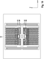
1 eine Draufsicht auf einen konventionellen mikromechanischen z-Inertialsensors; -
2 den konventionellen mikromechanischen z-Inertialsensor von1 in einer perspektivischen Ansicht; -
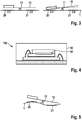
3 einen stark vereinfachten konventionellen mikromechanischen z-Inertialsensor in zwei Querschnittsansichten; -
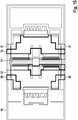
4 einen konventionellen mikromechanischen z-Inertialsensor in einem Gehäuse; -
5 eine prinzipielle Darstellung einer parasitären Verbiegung eines herkömmlichen mikromechanischen z-Inertialsensors; -
6 ,7 simulationstechnische Darstellungen einer parasitären Verbiegung eines herkömmlichen mikromechanischen Inertialsensors; -
8 ,9 simulationstechnische Darstellungen der mikromechanischen Inertialsensoren von6 und7 mit Kompensationselektroden; -
10 eine Draufsicht auf einen konventionellen mikromechanischen in-plane-Inertialsensor; -
11 eine Draufsicht auf eine Ausführungsform eines erfindungsgemäßen mikromechanischen in-plane-Inertialsensors mit Kompensationselektroden; -
12 ,13 simulationstechnische Darstellung von Verbiegungen eines Substrats eines mikromechanischen Inertialsensors samt Kompensationselektroden; -
14 eine Draufsicht auf einen konventionellen mikromechanischen in-plane-Inertialsensor; -
15 eine Draufsicht auf eine Ausführungsform eines erfindungsgemäßen mikromechanischen in-plane-Inertialsensors mit Kompensationselektroden; -
16-18 prinzipielle Darstellungen von Deformationen eines Substrats eines mikromechanischen in-plane Inertialsensors, die kompensiert werden können; -
19 ,20 prinzipielle Darstellungen von unkompensierten und kompensierten Ausgangssignalen von mikromechanischen Inertialsensoren; und -
21 einen prinzipiellen Ablauf eines Verfahrens zum Herstellen eines vorgeschlagenen mikromechanischen Inertialsensors.
-
1 a plan view of a conventional micromechanical z inertial sensor; -
2nd the conventional micromechanical z inertial sensor from1 in a perspective view; -
3rd a greatly simplified conventional micromechanical z inertial sensor in two cross-sectional views; -
4th a conventional micromechanical z inertial sensor in a housing; -
5 a schematic representation of a parasitic bending of a conventional micromechanical z-inertial sensor; -
6 ,7 simulation-technical representations of a parasitic bending of a conventional micromechanical inertial sensor; -
8th ,9 Simulation technical representations of the micromechanical inertial sensors from6 and7 with compensation electrodes; -
10th a plan view of a conventional micromechanical in-plane inertial sensor; -
11 a plan view of an embodiment of a micromechanical in-plane inertial sensor according to the invention with compensation electrodes; -
12th ,13 simulation representation of bending of a substrate of a micromechanical inertial sensor including compensation electrodes; -
14 a plan view of a conventional micromechanical in-plane inertial sensor; -
15 a plan view of an embodiment of a micromechanical in-plane inertial sensor according to the invention with compensation electrodes; -
16-18 basic representations of deformations of a substrate of a micromechanical in-plane inertial sensor that can be compensated; -
19th ,20th basic representations of uncompensated and compensated output signals from micromechanical inertial sensors; and -
21 a basic sequence of a method for producing a proposed micromechanical inertial sensor.
Beschreibung von AusführungsformenDescription of embodiments
Ein Kerngedanke der Erfindung ist es insbesondere, einen mikromechanischen Inertialsensor mit verbesserter Offsetstabilität und Sensiercharakteristik zu realisieren.A core idea of the invention is in particular a micromechanical inertial sensor with improved offset stability and sensing characteristics.
Die
Man erkennt in einer ersten mikromechanischen Funktionsschicht ausgebildete Detektionselektroden
Die beiden Ansichten von
Allerdings treten in der Praxis zahlreiche parasitäre externe Effekte auf, die die gemessenen Kapazitäten
In diesen Fällen ändern diese parasitären Deformationen die Kapazitäten
Ein Kerngedanke der Erfindung ist es insbesondere, diesen Signaloffset zu minimieren.A key idea of the invention is in particular to minimize this signal offset.
Die simulationstechnische Ansicht von
Vorzugsweise sind die Detektionselektroden
Auf diese Weise wird ein ausbalanciertes Bereitstellen der Kapazitäten zwischen der seismischen Masse
Das vorgeschlagene Kompensationsprinzip ist vorteilhaft nicht nur, wie bisher erläutert, auf mikromechanische out-of-plane-Inertialsensoren anwendbar, sondern auch auf mikromechanische in-plane-Inertialsensoren, bei denen sich die seismische Masse
Die
Die Draufsicht von
Die
Die
Man erkennt in allen Fällen, dass bei Verwendung von Kompensationselektroden
In einem Schritt
In einem Schritt
In einem Schritt
In einem Schritt
Obwohl die Erfindung vorgehend anhand von konkreten Ausführungsbeispielen beschrieben worden ist, kann der Fachmann vorgehend auch nicht oder nur teilweise offenbarte Ausführungsformen realisieren, ohne vom Kern der Erfindung abzuweichen.Although the invention has been described above on the basis of specific exemplary embodiments, the person skilled in the art can also implement embodiments which have not been disclosed or only partially disclosed without departing from the essence of the invention.
ZITATE ENTHALTEN IN DER BESCHREIBUNG QUOTES INCLUDE IN THE DESCRIPTION
Diese Liste der vom Anmelder aufgeführten Dokumente wurde automatisiert erzeugt und ist ausschließlich zur besseren Information des Lesers aufgenommen. Die Liste ist nicht Bestandteil der deutschen Patent- bzw. Gebrauchsmusteranmeldung. Das DPMA übernimmt keinerlei Haftung für etwaige Fehler oder Auslassungen.This list of documents listed by the applicant has been generated automatically and is only included for the better information of the reader. The list is not part of the German patent or utility model application. The DPMA assumes no liability for any errors or omissions.
Zitierte PatentliteraturPatent literature cited
- EP 0244581 A1 [0003]EP 0244581 A1 [0003]
- EP 0773443 A1 [0003]EP 0773443 A1 [0003]
Claims (8)
Priority Applications (2)
| Application Number | Priority Date | Filing Date | Title |
|---|---|---|---|
| DE102018217841.0A DE102018217841A1 (en) | 2018-10-18 | 2018-10-18 | Micromechanical inertial sensor |
| CN201910992349.0A CN111071982B (en) | 2018-10-18 | 2019-10-18 | Micromachined Inertial Sensors |
Applications Claiming Priority (1)
| Application Number | Priority Date | Filing Date | Title |
|---|---|---|---|
| DE102018217841.0A DE102018217841A1 (en) | 2018-10-18 | 2018-10-18 | Micromechanical inertial sensor |
Publications (1)
| Publication Number | Publication Date |
|---|---|
| DE102018217841A1 true DE102018217841A1 (en) | 2020-04-23 |
Family
ID=70310482
Family Applications (1)
| Application Number | Title | Priority Date | Filing Date |
|---|---|---|---|
| DE102018217841.0A Pending DE102018217841A1 (en) | 2018-10-18 | 2018-10-18 | Micromechanical inertial sensor |
Country Status (2)
| Country | Link |
|---|---|
| CN (1) | CN111071982B (en) |
| DE (1) | DE102018217841A1 (en) |
Cited By (2)
| Publication number | Priority date | Publication date | Assignee | Title |
|---|---|---|---|---|
| DE102020210135A1 (en) | 2020-08-11 | 2022-02-17 | Robert Bosch Gesellschaft mit beschränkter Haftung | Microelectromechanical system, method for producing a microelectromechanical system |
| WO2022264816A1 (en) * | 2021-06-16 | 2022-12-22 | ローム株式会社 | Acceleration sensor |
Citations (2)
| Publication number | Priority date | Publication date | Assignee | Title |
|---|---|---|---|---|
| EP0244581A1 (en) | 1986-04-04 | 1987-11-11 | Robert Bosch Gmbh | Sensor for the automatic triggering of passenger security devices |
| EP0773443A1 (en) | 1995-11-07 | 1997-05-14 | TEMIC TELEFUNKEN microelectronic GmbH | Micro-machined accelerometer |
Family Cites Families (9)
| Publication number | Priority date | Publication date | Assignee | Title |
|---|---|---|---|---|
| DE10350536B3 (en) * | 2003-10-29 | 2005-06-23 | Robert Bosch Gmbh | Method for reducing effect of substrate potential on output signal of micromechanical sensor e.g. capacitive acceleration sensor, using application of opposite voltages to capacitor outer electrodes during compensation clock |
| DE102004021693B4 (en) * | 2004-04-30 | 2008-11-06 | Austriamicrosystems Ag | Micromechanical sensor |
| DE102009026462B4 (en) * | 2009-05-26 | 2023-03-30 | Robert Bosch Gmbh | accelerometer |
| CN201628722U (en) * | 2010-02-09 | 2010-11-10 | 杭州电子科技大学 | A Micro Inertial Sensor with Large Detection Capacitance |
| DE102010038809A1 (en) * | 2010-08-03 | 2012-02-09 | Robert Bosch Gmbh | Inertial sensor and method of manufacturing an inertial sensor |
| DE102011080993A1 (en) * | 2011-08-16 | 2013-02-21 | Robert Bosch Gmbh | Acceleration sensor for use with electronic stability program system in automobile sector, has substrate and seismic mass that is deflected against substrate on basis of outer acceleration force along deflection direction |
| ITTO20130174A1 (en) * | 2013-03-05 | 2014-09-06 | St Microelectronics Srl | MEMS AND RELATIVE MICROMECHANICAL STRUCTURE WITH INTEGRATED COMPENSATION OF THERMO-MECHANICAL DEFORMATIONS |
| DE102013212059B4 (en) * | 2013-06-25 | 2024-06-06 | Robert Bosch Gmbh | Micromechanical inertial sensor |
| DE102014211054A1 (en) * | 2014-06-10 | 2015-12-17 | Robert Bosch Gmbh | Micromechanical acceleration sensor |
-
2018
- 2018-10-18 DE DE102018217841.0A patent/DE102018217841A1/en active Pending
-
2019
- 2019-10-18 CN CN201910992349.0A patent/CN111071982B/en active Active
Patent Citations (2)
| Publication number | Priority date | Publication date | Assignee | Title |
|---|---|---|---|---|
| EP0244581A1 (en) | 1986-04-04 | 1987-11-11 | Robert Bosch Gmbh | Sensor for the automatic triggering of passenger security devices |
| EP0773443A1 (en) | 1995-11-07 | 1997-05-14 | TEMIC TELEFUNKEN microelectronic GmbH | Micro-machined accelerometer |
Cited By (3)
| Publication number | Priority date | Publication date | Assignee | Title |
|---|---|---|---|---|
| DE102020210135A1 (en) | 2020-08-11 | 2022-02-17 | Robert Bosch Gesellschaft mit beschränkter Haftung | Microelectromechanical system, method for producing a microelectromechanical system |
| US12528694B2 (en) | 2020-08-11 | 2026-01-20 | Robert Bosch Gmbh | Microelectromechanical system and method for manufacturing a microelectromechanical system |
| WO2022264816A1 (en) * | 2021-06-16 | 2022-12-22 | ローム株式会社 | Acceleration sensor |
Also Published As
| Publication number | Publication date |
|---|---|
| CN111071982B (en) | 2024-04-16 |
| CN111071982A (en) | 2020-04-28 |
Similar Documents
| Publication | Publication Date | Title |
|---|---|---|
| DE102008040855B4 (en) | Triaxial accelerometer | |
| EP2274627B1 (en) | Micromechanical component and method for operating a micromechanical component | |
| DE102009026462B4 (en) | accelerometer | |
| DE102008040525B4 (en) | Micromechanical sensor element | |
| DE102009000167A1 (en) | sensor arrangement | |
| DE102008017156A1 (en) | Micromechanical acceleration sensor | |
| EP2394177B1 (en) | Acceleration sensor and method for operating an acceleration sensor | |
| EP2082189B1 (en) | Rotational rate sensor having a quadrature compensation structure | |
| DE102021200483A1 (en) | Triaxial yaw rate sensor with a substrate and a double rotor | |
| DE19810534A1 (en) | Multiple axis acceleration sensor | |
| DE102017219901B3 (en) | Micromechanical z-inertial sensor | |
| DE112009003522T5 (en) | accelerometer | |
| DE102012200740A1 (en) | Micromechanical component and method for producing a micromechanical component | |
| DE102008041327A1 (en) | Three-axis accelerometer | |
| WO2014177243A1 (en) | Acceleration sensor and method for producing an acceleration sensor | |
| DE102009047018A1 (en) | Method for adjusting an acceleration sensor and acceleration sensor | |
| WO1992014161A1 (en) | Capacitive acceleration sensor | |
| DE102015222532A1 (en) | Micromechanical structure for an acceleration sensor | |
| DE102018217841A1 (en) | Micromechanical inertial sensor | |
| DE102019200843B4 (en) | Micromechanical, capacitive evaluable component | |
| DE102011007350A1 (en) | Force-moment sensor for performing tactile measurement of force, moment and deformation, has support element spaced apart from set of supplementary parallel spring assemblies, and another support element that supports sensor at frame | |
| WO2017194376A1 (en) | Micromechanical sensor and method for producing a micromechanical sensor | |
| DE102009028371B4 (en) | Micromechanical component with rocker structure | |
| DE102014211054A1 (en) | Micromechanical acceleration sensor | |
| DE102019200839A1 (en) | Micromechanical inertial sensor |
Legal Events
| Date | Code | Title | Description |
|---|---|---|---|
| R012 | Request for examination validly filed |