DE102018217552B4 - SCREW-IN SYSTEM AND METHOD FOR SCREWING IN SCREW FOUNDATIONS - Google Patents
SCREW-IN SYSTEM AND METHOD FOR SCREWING IN SCREW FOUNDATIONS Download PDFInfo
- Publication number
- DE102018217552B4 DE102018217552B4 DE102018217552.7A DE102018217552A DE102018217552B4 DE 102018217552 B4 DE102018217552 B4 DE 102018217552B4 DE 102018217552 A DE102018217552 A DE 102018217552A DE 102018217552 B4 DE102018217552 B4 DE 102018217552B4
- Authority
- DE
- Germany
- Prior art keywords
- screw
- foundation
- boom
- screwing
- hydraulic cylinder
- Prior art date
- Legal status (The legal status is an assumption and is not a legal conclusion. Google has not performed a legal analysis and makes no representation as to the accuracy of the status listed.)
- Active
Links
- 238000000034 method Methods 0.000 title claims description 28
- XLYOFNOQVPJJNP-UHFFFAOYSA-N water Substances O XLYOFNOQVPJJNP-UHFFFAOYSA-N 0.000 claims abstract description 38
- 230000008878 coupling Effects 0.000 claims abstract description 14
- 238000010168 coupling process Methods 0.000 claims abstract description 14
- 238000005859 coupling reaction Methods 0.000 claims abstract description 14
- 230000033001 locomotion Effects 0.000 claims description 41
- 238000005553 drilling Methods 0.000 claims description 5
- 238000012360 testing method Methods 0.000 claims description 3
- 230000008569 process Effects 0.000 description 7
- 238000013461 design Methods 0.000 description 6
- 238000002347 injection Methods 0.000 description 6
- 239000007924 injection Substances 0.000 description 6
- 239000002184 metal Substances 0.000 description 5
- 239000000725 suspension Substances 0.000 description 5
- 239000003921 oil Substances 0.000 description 3
- 230000008901 benefit Effects 0.000 description 2
- 238000012937 correction Methods 0.000 description 2
- 230000007935 neutral effect Effects 0.000 description 2
- 230000001154 acute effect Effects 0.000 description 1
- 239000003570 air Substances 0.000 description 1
- 238000004873 anchoring Methods 0.000 description 1
- 230000008859 change Effects 0.000 description 1
- 238000011161 development Methods 0.000 description 1
- 230000018109 developmental process Effects 0.000 description 1
- 229910003460 diamond Inorganic materials 0.000 description 1
- 239000010432 diamond Substances 0.000 description 1
- 230000005484 gravity Effects 0.000 description 1
- 239000010720 hydraulic oil Substances 0.000 description 1
- 238000003780 insertion Methods 0.000 description 1
- 230000037431 insertion Effects 0.000 description 1
- 239000000463 material Substances 0.000 description 1
- 238000003825 pressing Methods 0.000 description 1
- 239000011435 rock Substances 0.000 description 1
- 239000000523 sample Substances 0.000 description 1
- 239000002689 soil Substances 0.000 description 1
- 238000012549 training Methods 0.000 description 1
Images
Classifications
-
- E—FIXED CONSTRUCTIONS
- E02—HYDRAULIC ENGINEERING; FOUNDATIONS; SOIL SHIFTING
- E02D—FOUNDATIONS; EXCAVATIONS; EMBANKMENTS; UNDERGROUND OR UNDERWATER STRUCTURES
- E02D5/00—Bulkheads, piles, or other structural elements specially adapted to foundation engineering
- E02D5/22—Piles
- E02D5/56—Screw piles
-
- E—FIXED CONSTRUCTIONS
- E02—HYDRAULIC ENGINEERING; FOUNDATIONS; SOIL SHIFTING
- E02D—FOUNDATIONS; EXCAVATIONS; EMBANKMENTS; UNDERGROUND OR UNDERWATER STRUCTURES
- E02D7/00—Methods or apparatus for placing sheet pile bulkheads, piles, mouldpipes, or other moulds
- E02D7/22—Placing by screwing down
Landscapes
- Engineering & Computer Science (AREA)
- Structural Engineering (AREA)
- Life Sciences & Earth Sciences (AREA)
- General Life Sciences & Earth Sciences (AREA)
- Mining & Mineral Resources (AREA)
- Paleontology (AREA)
- Civil Engineering (AREA)
- General Engineering & Computer Science (AREA)
- Earth Drilling (AREA)
Abstract
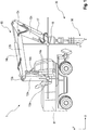
Einschraubsystem (1) für Schraubfundamente (50), aufweisendeinen Ausleger (10),ein Anbaugerät (30) mit einem Tiltantrieb (31) und einem Drehantrieb (32), undein Schraubfundament (50) mit einer offenen Bohrkrone (54),wobei das Anbaugerät (30) mit dem Ausleger (10) über einen Koppelbolzen (16) und einen Hydraulikzylinder (12) des Auslegers (10) schwenkbar verbunden ist und der Hydraulikzylinder (17) in eine Schwimmstellung verbringbar ist, in welcher die Kolbenstange des Hydraulikzylinders (17) im Wesentlichen kraftfrei verschiebbar ist,wobei der Drehantrieb (32) eine Aufnahme (33) für ein Schraubfundament (50) aufweist und über diese Aufnahme (33) mit dem Schraubfundament (50) lösbar verbunden ist, undwobei das Schraubfundament (50) in seinem Inneren eine Wasserstrahldüse (52) aufweist.Screw-in system (1) for screw foundations (50), comprising a boom (10), an attachment (30) with a tilt drive (31) and a rotary drive (32), and a screw foundation (50) with an open drill bit (54), the attachment (30) is pivotably connected to the boom (10) via a coupling pin (16) and a hydraulic cylinder (12) of the boom (10) and the hydraulic cylinder (17) can be brought into a floating position in which the piston rod of the hydraulic cylinder (17) can be displaced essentially without force, the rotary drive (32) having a receptacle (33) for a screw foundation (50) and being detachably connected to the screw foundation (50) via this receptacle (33), and the screw foundation (50) in its interior has a water jet nozzle (52).
Description
Die Erfindung betrifft ein Einschraubsystem sowie ein Verfahren zum Einschrauben von Schraubfundamenten, insbesondere von Schraubfundamenten großer Dimension ins Erdreich.The invention relates to a screw-in system and a method for screwing screw foundations, in particular screw foundations of large dimensions, into the ground.
Schraubfundamente, d. h. in der Regel als Hohlkörper ausgebildete Erdanker mit einer außenliegenden Schraubwendel werden durch Eindrehen ins Erdreich eingebracht. Dabei sind verschiedene Arten von Einschraubvorrichtungen sowie -verfahren bekannt. Schraubfundamente kleiner Dimension werden häufig von Hand oder mittels Handgeräten ins Erdreich eingeschraubt. Aus dem Stand der Technik sind jedoch auch Einschraubvorrichtungen bekannt, welche beispielsweise an Lafetten aufgehängt sind. Daneben sind auch Einschraubvorrichtungen bekannt, welche an Auslegern von Baggern befestigbar sind.Ground screws, d. H. Ground anchors, usually designed as hollow bodies, with an external helix are screwed into the ground. Various types of screw-in devices and methods are known. Small screw foundations are often screwed into the ground by hand or using hand tools. However, screw-in devices are also known from the prior art, which are suspended from mounts, for example. In addition, screw-in devices are also known which can be attached to the booms of excavators.
Der Ausleger eines Baggers weist in der Regel verschiedene Segmente bzw. Arme auf, welche über Hydraulikzylinder zueinander bewegbar verbunden sind. Das Einhalten einer vordefinierten Schraubrichtung gestaltet sich bei derartigen Einschraubvorrichtungen als schwierig, da der Ausleger mit dem Fortschritt des Schraubvorgangs abgesenkt wird und das Anbaugerät einer Kreisbahn folgt. Diese Kreisbahn muss jedoch in Längsrichtung des Baggerarms korrigiert werden, damit das Schraubfundament nicht von der Einschraubachse in eine unerwünschte Richtung gedrängt wird. Aus diesem Grund wird in
Aus
Weiterhin bekannt ist der Schraubankerantrieb der Firma Auger Torque. Ein Hydraulikmotor, welcher als Drehantrieb dient, ist über einen einzigen Bolzen schwenkbar an einem Ausleger aufgehängt. Zum besseren Handling des Drehantriebs wird die Aufhängung mit einer zusätzlichen Auflage angeboten. Die Auflage begrenzt die Schwenkbewegung um den Aufhängungsbolzen in eine Richtung, so dass ein Aufnehmen des Drehantriebs samt Schraubfundament ermöglicht wird. Nachteilig an einer derartigen Aufhängung ist die geringe Flexibilität sowie die begrenzte Korrekturmöglichkeit während des Eindrehvorgangs.Also known is the screw anchor drive from Auger Torque. A hydraulic motor, which serves as a rotary drive, is suspended from a boom so that it can pivot via a single bolt. The suspension is offered with an additional support for better handling of the rotary drive. The support limits the pivoting movement around the suspension bolt in one direction, so that the rotary drive and the screw foundation can be picked up. The disadvantage of such a suspension is the low flexibility and the limited possibility of correction during the screwing-in process.
Im Stand der Technik sind darüber hinaus sogenannte Tiltrotatoren als Anbaugeräte für Bagger bekannt. Tiltrotatoren werden in der Regel zwischen dem Ausleger des Baggers und der Baggerschaufel bzw. dem Anbaugerät angeordnet und ermöglichen sowohl ein seitliches Kippen der Schaufel mittels eines Hydraulikmotors oder -zylinders. Darüber hinaus besitzen manche Tiltrotatoren eine Drehfunktion der Schaufel um 360°. Diese Drehfunktion ist jedoch aufgrund der Ausgestaltung weder für einen Dauerbetrieb ausgelegt noch weisen derartige Rotatoren eine hinreichende Kraft zum Einschrauben von Schraubfundamenten großer Dimensionen auf. Üblicherweise liegen die maximalen Drehmomente derartiger Drehfunktionen im unteren bis mittleren 4-stelligen Nm-Bereich.In the prior art, so-called tiltrotators are also known as attachments for excavators. Tiltrotators are usually arranged between the boom of the excavator and the excavator shovel or the attachment and enable the shovel to be tilted sideways by means of a hydraulic motor or cylinder. In addition, some tiltrotators have a 360 ° rotation function for the shovel. However, due to the design, this rotating function is neither designed for continuous operation nor do such rotators have sufficient force to screw in screw foundations of large dimensions. The maximum torques of such rotary functions are usually in the lower to middle 4-digit Nm range.
Es besteht daher die Aufgabe, ein System sowie ein Verfahren zum Eindrehen von Schraubfundamenten bereitzustellten, welches ein einfaches Handling der Schraubfundamente ermöglicht und darüber hinaus Korrekturmöglichkeiten während des Eindrehens bereitstellt.The object is therefore to provide a system and a method for screwing in screw foundations which enables simple handling of the screw foundations and also provides correction options during screwing in.
Die gestellte Aufgabe wird durch ein Einschraubsystem gemäß Anspruch 1 sowie ein Verfahren gemäß Anspruch 11 gelöst. Bevorzugte Ausbildungen des erfindungsgemäßen Systems bzw. Verfahrens ergeben sich aus den jeweiligen Unteransprüchen.The object set is achieved by a screw-in system according to claim 1 and a method according to
Das erfindungsgemäße Einschraubsystem für Schraubfundamente weist einen Ausleger, ein Anbaugerät mit einem Tiltantrieb und einem Drehantrieb sowie ein Schraubfundament mit einer offenen Bohrkrone auf. Das Anbaugerät ist mit dem Ausleger über einen Löffelbolzen und einen Hydraulikzylinder des Auslegers schwenkbar verbunden. Der Hydraulikzylinder ist in eine Schwenkstellung verbringbar, in welcher die Kolbenstange des Hydraulikzylinders im Wesentlichen kraftfrei verschiebbar ist. Der Drehantrieb weist eine Aufnahme für ein Schraubfundament auf und ist über diese Aufnahme lösbar mit dem Schraubfundament verbunden. Das Schraubfundament weist in seinem Inneren eine Wasserstrahldüse auf.The screw-in system according to the invention for screw foundations has a boom, an attachment with a tilt drive and a rotary drive and a screw foundation with an open drill bit. The attachment is pivotably connected to the boom via a bucket pin and a hydraulic cylinder of the boom. The hydraulic cylinder can be brought into a pivoting position in which the piston rod of the hydraulic cylinder can be displaced essentially without force. The rotary drive has a receptacle for a screw foundation and is detachably connected to the screw foundation via this receptacle. The screw foundation has a water jet nozzle inside.
Ein Ausleger besteht in der Regel aus mehreren Armen, welche jeweils über ein Drehgelenk verbunden sind. Zusätzlich sind die Arme des Auslegers mit zumindest einem Hydraulikzylinder verbunden, so dass der Winkel von zwei benachbarten Armen zueinander veränderbar und einstellbar ist. Die Schwenkachsen sind dabei parallel zueinander angeordnet, so dass sich der Ausleger in einer Ebene bewegen lässt, welche im Folgenden als Bewegungsebene bezeichnet wird. Eine horizontale Richtung in dieser Ebene wird dabei als Längsrichtung bezeichnet.A boom usually consists of several arms, each of which has a swivel joint are connected. In addition, the arms of the boom are connected to at least one hydraulic cylinder so that the angle of two adjacent arms to one another can be changed and adjusted. The pivot axes are arranged parallel to one another so that the boom can be moved in a plane which is referred to below as the plane of movement. A horizontal direction in this plane is referred to as the longitudinal direction.
Das Anbaugerät weist zwei Bolzen auf, wobei ein erster Bolzen als Löffelbolzen bezeichnet wird, über welchen das Anbaugerät mit dem Ausleger an einem sogenannten Löffelstiel, d. h. dem letzten Arm des Auslegers, verbindbar bzw. verbunden ist. Ein zweiter Bolzen, welcher als Koppelbolzen bezeichnet wird, verbindet das Anbaugerät mit dem Hydraulikzylinder, welcher am Löffelstiel angeordnet ist. Die beiden Bolzen sind dabei ebenfalls orthogonal zur Bewegungsebene bzw. parallel zu den Schwenkachsen angeordnet. Über den Hydraulikzylinder lässt sich die Neigung des Anbaugeräts einstellen.The attachment has two bolts, a first bolt being referred to as a bucket pin, via which the attachment with the boom on a so-called dipper stick, i.e. H. the last arm of the boom, connectable or connected. A second bolt, which is referred to as a coupling bolt, connects the attachment to the hydraulic cylinder, which is arranged on the dipperstick. The two bolts are also arranged orthogonally to the plane of movement or parallel to the pivot axes. The inclination of the attachment can be adjusted via the hydraulic cylinder.
Der Tiltantrieb des Anbaugeräts ist vorzugsweise als Hydraulikmotor ausgebildet. Die Schwenkachse befindet sich vorzugsweise in der Bewegungsebene oder parallel dazu. Somit bilden die Schwenkachse des Löffelbolzens und die Schwenkachse des Tiltantriebs eine kardanische Aufhängung des Drehanatriebs. Der Tiltantrieb weist bevorzugt einen asymmetrischen Schwenkbereich auf. Der Schwenkbereich reicht aus einer Nullstellung in eine Richtung mindestens 90°, beispielsweise 95°, so dass der Drehantrieb und die Aufnahme derart geschwenkt werden können, dass am Boden liegende Schraubfundamente aufgenommen werden können. Die Aufnahme kann somit in eine horizontale Position geschwenkt werden. In die gegenüberliegende Richtung weist der Tiltantrieb einen geringeren Schwenkbereich auf. Dieser ist in der Regel dafür notwendig, um einen Winkelausgleich beim Eindrehen vornehmen zu können. Dieser Schwenkbereich liegt beispielsweise bei 25°.The tilt drive of the attachment is preferably designed as a hydraulic motor. The pivot axis is preferably located in the plane of movement or parallel to it. The pivot axis of the bucket pin and the pivot axis of the tilt drive thus form a cardanic suspension of the rotary drive. The tilt drive preferably has an asymmetrical swivel range. The swivel range extends from a zero position in one direction at least 90 °, for example 95 °, so that the rotary drive and the receptacle can be swiveled in such a way that screw foundations lying on the ground can be accommodated. The receptacle can thus be pivoted into a horizontal position. In the opposite direction, the tilt drive has a smaller swivel range. This is usually necessary in order to be able to make an angle compensation when screwing in. This swivel range is, for example, 25 °.
Die Schwimmstellung wird bevorzugt über eine Kurzschlussschaltung der beiden Kammern des Hydraulikzylinders bereitgestellt. Dabei wird die Kammer zum Ausfahren der Kolbenstange des Hydraulikzylinders mit der Druckkammer zum Einfahren der Kolbenstange kurzgeschlossen. Ein derartiges Kurzschließen kann beispielsweise über eine direkte Verbindung der beiden Kammern mittels einer Hydraulikleitung erfolgen. Über ein Ventil in der Verbindungsleitung ist die Schwimmstellung aktivierbar oder deaktivierbar. Aufgrund der unterschiedlichen Flächen auf der Stangen- und der Bodenseite im Hydraulikzylinder besteht in der Regel eine Ableitung zum Tankt. Diese kann auch dazu genutzt werden, um beispielsweise Druckspitzen in einem der Hydraulikkammern abdämpfen zu können. Bevorzugt wird diese Verbindung zum Hydrauliktank bei Überschreitung eines vordefinierten Maximaldrucks geöffnet. In einer alternativen Ausführungsform besteht keine direkte Verbindungsleitung zwischen den beiden Hydraulikkammern. Vielmehr werden die Leitungen, welche bereits zur Druckbeaufschlagung des Hydraulikzylinders vorhanden sind, verwendet und die Bereitstellung der Schwimmstellung erfolgt in einem Hydraulikblock. Im Hydraulikblock sind die Ventile zur Steuerung der einzelnen Druckkammern verbaut. Diese werden entsprechend geschalten, dass die beiden Druckkammern des Hydraulikzylinders miteinander verbunden sind.The floating position is preferably provided via a short-circuit circuit between the two chambers of the hydraulic cylinder. The chamber for extending the piston rod of the hydraulic cylinder is short-circuited with the pressure chamber for retracting the piston rod. Such a short-circuit can take place, for example, via a direct connection of the two chambers by means of a hydraulic line. The floating position can be activated or deactivated via a valve in the connection line. Due to the different areas on the rod side and the bottom side in the hydraulic cylinder, there is usually a discharge to the tank. This can also be used to dampen pressure peaks in one of the hydraulic chambers, for example. This connection to the hydraulic tank is preferably opened when a predefined maximum pressure is exceeded. In an alternative embodiment, there is no direct connection line between the two hydraulic chambers. Rather, the lines that are already available for applying pressure to the hydraulic cylinder are used and the floating position is provided in a hydraulic block. The valves for controlling the individual pressure chambers are built into the hydraulic block. These are switched accordingly so that the two pressure chambers of the hydraulic cylinder are connected to one another.
Der Drehantrieb des Anbaugeräts weist vorzugsweise einen Hydraulikmotor, insbesondere einen Radialkolbenmotor auf. Der Hydraulikmotor ist auf das Eindrehen von Schraubfundamenten großer Dimension ausgelegt und weist vorzugsweise ein Drehmoment von mindestens 40.000 Nm auf. Als Schraubfundamente größerer Dimension werden insbesondere Schraubfundamente verstanden, welche einen Durchmesser von wenigstens 30 cm und/oder eine Länge von mindestens 3 m, insbesondere mindestens 4 m aufweisen. Vorzugsweise ist der Hydraulikmotor mit zwei Gängen ausgestattet, wobei dann vorzugsweise der zweite Gang ein Drehmoment von 40.000 Nm und der erste Gang ein Drehmoment von 80.000 Nm bereitstellt.The rotary drive of the attachment preferably has a hydraulic motor, in particular a radial piston motor. The hydraulic motor is designed for driving screw foundations of large dimensions and preferably has a torque of at least 40,000 Nm. Screw foundations of larger dimensions are understood in particular to be screw foundations which have a diameter of at least 30 cm and / or a length of at least 3 m, in particular at least 4 m. The hydraulic motor is preferably equipped with two gears, the second gear then preferably providing a torque of 40,000 Nm and the first gear providing a torque of 80,000 Nm.
Vorzugsweise weist der Drehantrieb eine Mediendurchführung auf. Die Mediendurchführung ist vorzugsweise in Richtung der Rotationsachse des Drehantriebs ausgebildet und führt von dem Anbaugerät in Richtung der Aufnahme für Schraubfundamente. Somit lassen sich Funktionen über Medien wie beispielsweise Druckluft, Wasser oder Öl, insbesondere Hydrauliköl, zum sich drehenden Teil des Anbaugeräts hindurchführen und dort bzw. im Schraubfundament nutzen. Der Wasseranschluss dient dabei vorzugsweise zur Versorgung der Wasserstrahldüse im Inneren des Schraubfundaments und es wird vorzugsweise ein Wasserdruck von mindestens 100 bar bereitgestellt. Der Druckwasseranschluss ist jedoch darüber hinaus für weitere Anwendungen verwendbar.The rotary drive preferably has a media feed-through. The media duct is preferably designed in the direction of the axis of rotation of the rotary drive and leads from the attachment in the direction of the receptacle for screw foundations. Functions can thus be passed through media such as compressed air, water or oil, in particular hydraulic oil, to the rotating part of the attachment and used there or in the screw foundation. The water connection is preferably used to supply the water jet nozzle inside the screw foundation and a water pressure of at least 100 bar is preferably provided. However, the pressurized water connection can also be used for other applications.
Die Aufnahme für Schraubfundamente weist vorzugsweise eine Klemmeinrichtung, insbesondere eine hydraulische Klemmeinrichtung auf. Für die Druckversorgung der Klemmeinrichtung ist insbesondere der Hydraulikkreis des Baggers, welcher über die Mediendurchführung bereitgestellt wird, verwendbar. In einer bevorzugten Ausführungsform greift die Klemmvorrichtung ins Innere des Schraubfundaments hinein und klemmt dasselbe nach außen. In alternativen Ausbildungen liegen Klemmbacken außen am Schraubfundament bzw. innen und außen am Schraubfundament an. Bevorzugt weist die Klemmvorrichtung eine mechanische Verriegelung auf. Ferner bevorzugt ist über die Klemmkraft ein maximal übertragbares Drehmoment definierbar, um gegebenenfalls das Schraubfundament und/oder den Antrieb vor Beschädigung zu schützen. In einer alternativen Ausbildung wird das Schraubfundament über Schraubbolzen mit der Aufnahme für das Schraubfundament verbunden. Üblicherweise werden dabei die Verbindungspunkte am Schraubfundament verwendet, welche nach Einbringen des Schraubfundaments auch für die Verankerung des zu verankernden Gengenstandes, beispielsweise eines Trägers für einen Solardach Carport, verwendet werden.The receptacle for screw foundations preferably has a clamping device, in particular a hydraulic clamping device. In particular, the hydraulic circuit of the excavator, which is provided via the media duct, can be used to supply pressure to the clamping device. In a preferred embodiment, the clamping device engages into the interior of the screw foundation and clamps the same to the outside. In alternative designs, clamping jaws rest on the outside of the screw foundation or on the inside and outside of the screw foundation. Preferably, the Clamping device on a mechanical lock. Furthermore, a maximum transmittable torque can preferably be defined via the clamping force in order to protect the screw foundation and / or the drive from damage if necessary. In an alternative embodiment, the screw foundation is connected to the receptacle for the screw foundation via screw bolts. Usually, the connection points on the screw foundation are used which, after the screw foundation has been introduced, are also used for anchoring the object to be anchored, for example a carrier for a solar roof carport.
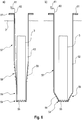
Das Schraubfundament weist vorzugsweise eine im Wesentlichen zylindrische Form auf. Im hinteren Bereich, d. h. im Bereich an welchem das Schraubfundament mit dem zu verankernden Gegenstand verbunden wird und welcher im eingedrehten Zustand sich im Bereich der Erdoberfläche befindet, weist das Schraubfundament vorzugsweise einen Flansch mit Bohrungen auf, über welchen der zu verankernde Gegenstand mittels Schraubbolzen verbindbar ist. Am gegenüberliegenden Ende des Schraubfundaments weist dieses eine Bohrkrone auf, welche offen ausgestaltet ist, d. h. eine Öffnung zum Inneren des Schraubfundaments bereitstellt. Die im wesentlichen zylindrische Form des Schraubfundaments ist vorzugsweise kaskadiert ausbildbar, d. h. das Schraubfundament weist zumindest zwei Bereiche mit zylindrischen Durchmessern auf, welche zur Bohrkrone hin geringer ausgebildet sind. Zwischen den einzelnen zylindrischen Bereichen weist das Schraubfundament sich verjüngende Bereiche, beispielsweise konische Bereiche auf. Auch ist der Bereich zur Bohrkrone hin konisch verjüngend ausbildbar. Das Schraubfundament weist dabei vorzugsweise eine am äußeren Umfang ausgebildete Schraubwendel auf. Die Schraubwendel ist vorzugsweise an die Bohrkrone anschließend ausgebildet.The screw foundation preferably has a substantially cylindrical shape. In the rear area, i. H. In the area where the screw foundation is connected to the object to be anchored and which is located in the screwed-in state in the area of the earth's surface, the screw foundation preferably has a flange with bores through which the object to be anchored can be connected by means of screw bolts. At the opposite end of the screw foundation this has a drill bit, which is designed to be open, d. H. provides an opening to the interior of the ground screw. The substantially cylindrical shape of the screw foundation can preferably be designed in a cascaded manner, i. H. the screw foundation has at least two areas with cylindrical diameters which are smaller towards the drill bit. Between the individual cylindrical areas, the screw foundation has tapering areas, for example conical areas. The area towards the drill bit can also be designed to taper conically. The screw foundation preferably has a helix formed on the outer circumference. The helix is preferably formed adjoining the drill bit.
Die Bohrkrone ist in üblicher Weise ausgebildet und weist beispielsweise Zähne auf, welche in die Wandung des Schraubfundaments integriert sind. Die gesamte Bohrkrone ist für harte Böden aus einem Hartmetall ausbildbar. Auch sind die Zähne beispielsweise mit Hartmetall oder mit Diamant bestückbar, um besonders harte Böden durchdringen zu können.The drill bit is designed in the usual way and has, for example, teeth which are integrated into the wall of the screw foundation. The entire drill bit can be designed from a hard metal for hard floors. The teeth can also be fitted with hard metal or diamond, for example, in order to be able to penetrate particularly hard floors.
Die Wasserstrahldüse ist vorzugsweise im Bereich der Bohrkrone angeordnet und steht beispielsweise von der Wandung des Schraubfundaments nach innen hin ab. Vorzugsweise wird die Wasserstrahldüse mit einer Wasserleitung versorgt, welche im Inneren des Schraubfundaments angeordnet ist, d. h. insbesondere an der Innenwand des Schraubfundaments befestigt ist. Die Wasserstrahldüse ist in einer Ausbildungsform von der Bohrkrone weg hin zum hinteren Ende des Schraubfundaments gerichtet, so dass sich der im Betrieb austretende Wasserstrahl parallel zur Wandung des Schraubfundaments erstreckt. Bei alternativen Ausführungsformen ist die Düse derart ausgerichtet, dass sich der Wasserstrahl radial oder tangential in Bezug auf das Schraubfundament ausbildet. Die Düse ist als Flachstrahldüse oder als Kegelstrahldüse ausbildbar, wobei bei einer Kegelstrahldüse ein spitzer Kegelwinkel bevorzugt wird. Bei einer tangentialen Anordnung ist die Düse vorzugsweise derart angeordnet, dass das Wasser die Düse entgegen der Eindrehrichtung des Schraubfundaments verlässt, um ein Verstopfen der Düse zu verhindern. Durch die Verwendung der Wasserstrahldüse wird die Reibung im Schraubfundament an der Innenseite des Schraubfundaments beim Einschrauben reduziert.The water jet nozzle is preferably arranged in the region of the drill bit and protrudes inwards, for example, from the wall of the screw foundation. The water jet nozzle is preferably supplied with a water line which is arranged in the interior of the screw foundation, i. H. in particular is attached to the inner wall of the screw foundation. In one embodiment, the water jet nozzle is directed away from the drill bit towards the rear end of the ground screw, so that the water jet emerging during operation extends parallel to the wall of the ground screw. In alternative embodiments, the nozzle is aligned such that the water jet is formed radially or tangentially with respect to the screw foundation. The nozzle can be designed as a flat jet nozzle or as a cone jet nozzle, an acute cone angle being preferred for a cone jet nozzle. In the case of a tangential arrangement, the nozzle is preferably arranged in such a way that the water leaves the nozzle in the opposite direction to the screwing-in direction of the screw foundation in order to prevent the nozzle from clogging. Using the water jet nozzle reduces the friction in the ground screw on the inside of the ground screw when screwing in.
Das Einschraubsystem weist vorzugsweise eine Positionierhilfe auf. Die Positionierhilfe dient dabei insbesondere der Positionierung der Schraubfundamentspitze, d. h. der Bohrkrone. In der Regel ist das Schraubfundament an einer vorbestimmten Position in den Erdboden einzuschrauben. Dieser Einschraubpunkt wird mit der Positionierhilfe definiert. Die Positionierhilfe ist dabei vorzugsweise derart ausgestaltet, dass sie eine runde äußere Form aufweist, welche im Wesentlichen dem Innendurchmesser der Bohrkrone entspricht oder geringfügig kleiner ist. Somit lässt sich die Bohrkrone um die Positionierhilfe herum auf dem Erdboden aufsetzen. Anschließend kann das Schraubfundament in Einschraubrichtung ausgerichtet werden, indem das hintere Ende des Schraubfundamentes entsprechend positioniert wird. Die Positionierhilfe weist darüber hinaus vorzugsweise einen Pflock auf, welcher in den Erdboden zur Fixierung eingebracht wird. Als Positionierhilfe wird eine formkongruente Ausbildung zum Schraubfundament bevorzugt, über welche die Position des Schraubfundaments definiert wird.The screw-in system preferably has a positioning aid. The positioning aid is used in particular to position the screw foundation tip, i.e. H. the drill bit. As a rule, the screw foundation is to be screwed into the ground at a predetermined position. This screw-in point is defined with the positioning aid. The positioning aid is preferably designed in such a way that it has a round outer shape which essentially corresponds to the inner diameter of the drill bit or is slightly smaller. Thus, the drill bit can be placed on the ground around the positioning aid. The screw foundation can then be aligned in the screwing direction by positioning the rear end of the screw foundation accordingly. The positioning aid also preferably has a stake which is inserted into the ground for fixation. A form of congruent shape to the screw foundation, via which the position of the screw foundation is defined, is preferred as a positioning aid.
In einer bevorzugten Ausführungsform weist das Anbaugerät eine Kröpfung auf. Die Kröpfung ist dabei derart ausgebildet, dass die Rotationsachse des Drehantriebs und die Achse des Kuppelbolzens windschief zueinander verlaufen. Somit ist die Rotationsachse des Drehantriebs insbesondere parallel zur Bewegungsebene in der Nullstellung des Tiltantriebs angeordnet. Die Kröpfung hat zum einen den Vorteil, dass beim Aufnehmen des Schraubfundaments in einer liegenden, horizontalen Position vom Erdboden der Tiltantrieb einen größeren Abstand zum Erdboden aufweist und somit das gesamte Anbaugerät einen größeren Abstand zum Erdboden aufweist. Dies ermöglicht eine bessere Handhabung und verhindert eine Beschädigung des Anbaugeräts bzw. des Auslegers. Darüber hinaus wird durch den Achsversatz zwischen Tiltantrieb und Drehantrieb beim Eindrehen ein Drehmoment erzeugt. Der Achsversatz zwischen Drehantrieb und die Eindrehrichtung sind dabei derart ausgebildet, dass das aus dem Achsversatz resultierende Drehmoment dem Eindrehdrehmoment entgegenwirkt. Dadurch werden die Kräfte auf den Aufleger reduziert, was die Genauigkeit des Eindrehvorgangs erhöht.In a preferred embodiment, the attachment has a crank. The crank is designed such that the axis of rotation of the rotary drive and the axis of the coupling bolt are skewed to one another. The axis of rotation of the rotary drive is thus arranged, in particular, parallel to the plane of movement in the zero position of the tilt drive. On the one hand, the offset has the advantage that when the screw foundation is picked up in a lying, horizontal position from the ground, the tilt drive has a greater distance from the ground and thus the entire attachment has a greater distance from the ground. This enables better handling and prevents damage to the attachment or the boom. In addition, the axial offset between the tilt drive and rotary drive generates a torque when screwing in. The axial offset between the rotary drive and the screw-in direction are designed in such a way that the off-axis resulting torque counteracts the screw-in torque. This reduces the forces on the trailer, which increases the accuracy of the screwing-in process.
Vorzugsweise handelt es sich bei dem Ausleger um den Ausleger eines Baggers. Baggerausleger weisen in der Regel drei oder vier Arme auf, welche über Hydraulikzylinder schwenkbar miteinander verbunden sind. Die Schwenkachsen zwischen den einzelnen Armen sind dabei rechtwinklig zur Bewegungsebene ausgebildet, in welcher sich der Ausleger bewegt. Die gesamte Bewegungsebene des Auslegers ist darüber hinaus drehbar am Oberwagen in einer Drehachse und/oder über das Drehgelenk zwischen Ober- und Unterwagen drehbar. Der Bagger ist dabei derart modifiziert, dass der letzte Hydraulikzylinder, über welchen das Anbaugerät verbindbar ist, eine erfindungsgemäße Schwimmstellung aufweist.The boom is preferably the boom of an excavator. Excavator booms usually have three or four arms which are pivotably connected to one another via hydraulic cylinders. The pivot axes between the individual arms are designed at right angles to the plane of movement in which the boom moves. The entire plane of movement of the boom can also be rotated on the superstructure in an axis of rotation and / or rotatable between the superstructure and the undercarriage via the pivot joint. The excavator is modified in such a way that the last hydraulic cylinder, via which the attachment can be connected, has a floating position according to the invention.
Das erfindungsgemäße Einschraubsystem weist im Wesentlichen vier Elemente, d. h. den Ausleger vorzugsweise samt Bagger, das Anbaugerät, das Schraubfundament und gegebenenfalls eine Positionierhilfe auf. Vom Erfindungsgedanken soll dabei umfasst sein, dass diese vier Elemente auch selbständig ohne die jeweils anderen Elemente offenbart sind und jeweils eine selbstständige Erfindung darstellen.The screw-in system according to the invention has essentially four elements, i. H. the boom, preferably including the excavator, the attachment, the screw foundation and, if necessary, a positioning aid. The idea of the invention should include the fact that these four elements are also disclosed independently without the respective other elements and each represent an independent invention.
Ein weiterer Aspekt der Erfindung betrifft ein Verfahren zum Einschrauben von Schraubfundamenten mit folgenden Schritten: Aufnehmen des Schraubfundaments aus einer Transportposition des Schraubfundaments mit einem Anbaugerät an einem Ausleger, Schwenken des Schraubfundaments über einen Tiltantrieb, Positionieren der Bohrkrone am Eindrehpunkt auf der Erdoberfläche, Ausrichten der Längsachse des Schraubfundaments in Eindrehrichtung, Einschalten einer Schwimmstellung des Anbaugeräts, Eindrehen des Schraubfundaments, wobei ins Innere des Schraubfundaments Wasser eingespritzt wird.Another aspect of the invention relates to a method for screwing in screw foundations with the following steps: picking up the screw foundation from a transport position of the screw foundation with an attachment on a boom, pivoting the screw foundation via a tilt drive, positioning the drill bit at the point of rotation on the surface of the earth, aligning the longitudinal axis of the screw foundation in the direction of screwing, switching on a floating position of the attachment, screwing in the screw foundation, whereby water is injected into the interior of the screw foundation.
Vorzugsweise umfasst das Verfahren das Einbringen einer Positionierhilfe im Bereich des Erdbodens, insbesondere in den Erdboden, vor dem Positionieren der Bohrkrone des Schraubfundaments. Die Positionierhilfe dient insbesondere dazu, den Startpunkt des Eindrehvorgangs festzulegen. Dabei greift die Positionierhilfe im Wesentlichen formkongruent in die Bohrkrone im Inneren ein. Alternativ kann die Positionierhilfe auch das Schraubfundament umgeben. Bevorzugt weißt die Positionierhilfe eine kreisrunde Außenkontur auf und vorzugsweise einen Dorn, mit welchem sie im Erdboden befestigt bzw. positioniert wird. Bevorzugt wird der Dorn in einem Bohrloch einer Probebohrung befestigt. Probebohrungen werden mit herkömmlichen Erdbohrern durchgeführt und dafür verwendet, den Erdboden zu sondieren und gegebenenfalls das Eindrehmoment aufzuzeichnen. Darüber lassen sich Rückschlüsse auf die vorhandenen Gesteinsschichten ziehen. Die daraus gewonnen Kenntnisse haben einen Einfluss auf den Einschraubvorgang des Schraubfundaments beispielsweise hinsichtlich der Wahl des Schraubfundaments, der Bohrkrone oder das zu erwartende Drehmoment und gegebenenfalls das Einspritzen des Wassers ins Innere des Schraubfundaments.The method preferably includes the introduction of a positioning aid in the area of the ground, in particular in the ground, before the drilling bit of the screw foundation is positioned. The positioning aid is used in particular to determine the starting point of the screwing-in process. The positioning aid engages in the interior of the drill bit with essentially congruent shape. Alternatively, the positioning aid can also surround the screw foundation. The positioning aid preferably has a circular outer contour and preferably a mandrel with which it is fastened or positioned in the ground. The mandrel is preferably fastened in a borehole of a test borehole. Test drillings are carried out with conventional auger and are used to probe the ground and, if necessary, to record the insertion torque. This allows conclusions to be drawn about the existing rock strata. The knowledge gained from this has an influence on the screwing process of the screw foundation, for example with regard to the choice of the screw foundation, the drill bit or the torque to be expected and, if necessary, the injection of water into the interior of the screw foundation.
In einer ersten Alternative des erfindungsgemäßen Verfahrens werden während des Eindrehens zumindest zwei Hydraulikzylinder derart bewegt, dass das Schaubfundament in Eindrehrichtung gehalten wird. Somit wird der Drehantrieb entlang seiner Rotationsachse bewegt. Hierzu werden vorzugsweise der Hydraulikzylinder zur Höhenverstellung des Auslegers und der Hydraulikzylinder zum Bewegen des Löffelstiels synchron bewegt. Typischerweise übt das Ende eines Arms des Auslegers eine kreisförmige Bewegung aus, sofern lediglich ein Hydraulikzylinder des Auslegers bewegt wird. Beim Eindrehen eines Schraubfundaments muss jedoch das Anbaugerät auf einer Gerade bewegt werden, welche durch die Drehachse des Drehantriebs definiert ist. Andernfalls werden seitliche Kräfte ins Schraubfundament eingeleitet, was zu einer Aufweitung des Bohrlochs und zu einer geringeren Stabilität des Schraubfundaments führt. Zudem werden die Einschraubmomente vergrößert, da es zur erhöhten Reibung kommt. Eine bevorzugte Linearbewegung des Anbaugeräts ist beispielsweise durch eine geeignete gekoppelte Bewegung von zumindest zwei Armen des Auslegers gleichzeitig durchführbar. Diese Koppelbewegung kann beispielsweise über die Steuerung des Auslegers realisiert werden. In einer einfachen Ausbildung ist die Bewegung durch den Fahrzeugführer gekoppelt, welcher über zwei Joysticks die beiden Bewegungen parallel realisiert.In a first alternative of the method according to the invention, at least two hydraulic cylinders are moved during screwing in such that the screw foundation is held in the screwing direction. The rotary drive is thus moved along its axis of rotation. For this purpose, the hydraulic cylinder for adjusting the height of the boom and the hydraulic cylinder for moving the dipper stick are preferably moved synchronously. Typically, the end of an arm of the boom exerts a circular movement, provided that only a hydraulic cylinder of the boom is moved. When screwing in a screw foundation, however, the attachment must be moved on a straight line which is defined by the axis of rotation of the rotary drive. Otherwise, lateral forces are introduced into the ground screw, which leads to a widening of the borehole and reduced stability of the ground screw. In addition, the screwing-in torques are increased because there is increased friction. A preferred linear movement of the attachment can be carried out simultaneously, for example, by a suitable coupled movement of at least two arms of the boom. This coupling movement can be implemented, for example, by controlling the boom. In a simple design, the movement is coupled by the vehicle driver, who implements the two movements in parallel using two joysticks.
In einer alternativen Ausbildung wird lediglich ein Arm des Auslegers über einen der Hydraulikzylinder bewegt. Gleichzeitig führt beispielsweise ein Bagger, auf welchem der Ausleger befestigt ist, eine Relativbewegung, insbesondere eine Fahrbewegung in der Gestalt aus, dass das Schraubfundament in Eindrehrichtung gehalten wird und somit das Anbaugerät eine Linearbewegung auf einer Gerade ausführt. Eine derartige Fahrbewegung kann zum einen eine aktive Fahrbewegung, d. h. eine durch den Antriebsmotor des Fahrzeugs, insbesondere des Baggers durchgeführt werden oder durch eine passive Fahrbewegung in der Gestalt, dass sich das Fahrzeug auf Grund der Einschraubbewegung sowie der Bewegung des Auslegers zwangsbewegt wird. Dabei wird der Fahrantrieb kraftfrei geschaltet bzw. entkoppelt. Die Fahrbewegung erfolgt entlang der Bewegungsebene insbesondere in Längsrichtung.In an alternative embodiment, only one arm of the boom is moved over one of the hydraulic cylinders. At the same time, for example, an excavator on which the boom is attached performs a relative movement, in particular a travel movement, in such a way that the screw foundation is held in the screwing direction and the attachment thus performs a linear movement on a straight line. Such a travel movement can be an active travel movement, i. H. one can be carried out by the drive motor of the vehicle, in particular the excavator, or by a passive travel movement in the form that the vehicle is forced to move due to the screwing-in movement and the movement of the boom. The travel drive is switched or decoupled without force. The travel movement takes place along the plane of movement, in particular in the longitudinal direction.
Über den Ausleger wird während des Eindrehens eine Kraft in Axialrichtung des Schraubfundaments auf das Schraubfundament aufgebraucht. Diese Kraft entspricht dabei einer Vorschubkraft, um das Schraubfundament in den Erdboden einzutreiben. Die Kraft kann insbesondere dahingehend gesteuert werden, dass die Vorschubbewegung des Schraubfundaments mit der Drehbewegung in der Gestalt korreliert, dass das Schraubfundament gemäß der Gewindesteigung eingeschraubt wird. Die Einschraubkraft wird insbesondere über das Fahrzeuggewicht beispielsweise des Baggers aufgebracht, indem dieses zumindest teilweise bevorzugt vom Erdboden angehoben wird. So besteht beispielsweise die Möglichkeit, dass bei einem zweiachsigen Fahrzeug sich eine Achse bzw. deren Räder vom Erdboden abheben. Analoges gilt selbstverständlich auch für ein Kettenfahrzeug, indem sich Teile der Kette vom Erdboden abheben.During the screwing in, a force in the axial direction of the Ground screw used up on the ground screw. This force corresponds to a feed force to drive the ground screw into the ground. The force can in particular be controlled in such a way that the advancing movement of the screw foundation correlates with the rotary movement in the form that the screw foundation is screwed in according to the thread pitch. The screwing-in force is applied in particular via the vehicle weight, for example of the excavator, in that this is preferably at least partially raised from the ground. For example, in a two-axle vehicle, there is the possibility that an axle or its wheels will lift off the ground. The same applies, of course, to a tracked vehicle in that parts of the chain lift off the ground.
Bevorzugt wird das Wasser ins Innere des Schraubfundaments mit einem Wasserdruck von mindestens 100 bar eingespritzt. Durch das Einspritzen von Wasser mit Hochdruck wird die Reibung zwischen dem Erdboden, insbesondere einem Einschraubkuchen im Inneren des Schraubfundaments, und dem Schraubfundament reduziert. Dabei wird das Wasser vorzugsweise entlang der Innenwand des Schraubfundaments entlanggespritzt, um den Einschraubkuchen abzulösen. Die Wasserzuleitung sowie die Düse, über welche das Wasser eingespritzt wird, verbleiben in der Regel im verankerten Schraubfundament und somit im Erdboden. Das unter Druck stehende Wasser wird insbesondere durch die Mediendurchführung im Anbaugerät bereitgestellt und beispielsweise von einem externen Gerät wie einem Hochdruckreiniger erzeugt.The water is preferably injected into the interior of the screw foundation with a water pressure of at least 100 bar. By injecting water at high pressure, the friction between the ground, in particular a screw-in cake inside the screw foundation, and the screw foundation is reduced. The water is preferably sprayed along the inner wall of the screw foundation in order to loosen the screw-in cake. The water supply line and the nozzle through which the water is injected usually remain in the anchored screw foundation and thus in the ground. The pressurized water is provided in particular through the media duct in the attachment and is generated, for example, by an external device such as a high-pressure cleaner.
Zur weiteren Reduzierung der Reibung ist vorzugsweise die Eindrehbewegung zumindest zeitweise von einer Vibration in Radialrichtung überlagert. Die Vibration in Radialrichtung wird beispielsweise über eine Unwucht oder ein Exzenter im Drehantrieb bereitgestellt. Vorzugsweise erfolgt die Radialvibration entgegen der Eindrehrichtung und mit einer größeren Umlaufgeschwindigkeit als die Eindrehgeschwindigkeit.To further reduce the friction, the screwing-in movement is preferably at least temporarily superimposed by a vibration in the radial direction. The vibration in the radial direction is provided, for example, via an imbalance or an eccentric in the rotary drive. The radial vibration preferably takes place opposite to the screwing-in direction and at a higher rotational speed than the screwing-in speed.
Das erfindungsgemäße Verfahren wird vorzugsweise mit einem vorstehend beschriebenen Einschraubsystem für Schraubfundamente bzw. mit deren Einzelelementen bestehend aus Ausleger, Anbaugerät, Schraubfundament und Positionierhilfe durchgeführt. Die beschriebenen strukturellen Merkmale der Vorrichtung bzw. deren Einzelelementen sollen somit auch vom Verfahren in bevorzugter Weise erfasst sein.The method according to the invention is preferably carried out with a screw-in system for screw foundations described above or with their individual elements consisting of a boom, attachment, screw foundation and positioning aid. The described structural features of the device or its individual elements should therefore also be covered in a preferred manner by the method.
Die erfindungsgemäße Lehre wird im Folgenden anhand von Figuren näher erläutert. Dabei zeigt:
-
1 eine Seitenansicht eines erfindungsgemäßen Einschraubsystems für Schraubfundamente, -
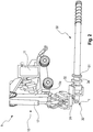
2 eine Vorderansicht eines erfindungsgemäßen Einschraubsystems für Schraubfundamente, -
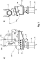
3a, b eine Seitenansicht und eine Rückansicht eines erfindungsgemäßen Anbaugeräts, -
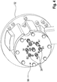
4 eine Mediendurchführung an einem erfindungsgemäßen Drehantrieb, -
5 ein erfindungsgemäßes Schraubfundament samt Bohrkrone an einem erfindungsgemäßen Anbaugerät, -
6a, b zwei Ausführungsformen eines erfindungsgemäßen Schraubfundaments, und -
7 eine Ausführungsform einer erfindungsgemäßen Wasserstrahldüse
-
1 a side view of a screw-in system according to the invention for screw foundations, -
2 a front view of a screw-in system according to the invention for screw foundations, -
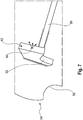
3a, b a side view and a rear view of an attachment according to the invention, -
4th a media duct on a rotary drive according to the invention, -
5 a screw foundation according to the invention including a drill bit on an attachment according to the invention, -
6a, b two embodiments of a screw foundation according to the invention, and -
7th an embodiment of a water jet nozzle according to the invention
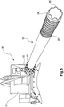
In
In der in
In
In
In
In
In
BezugszeichenlisteList of reference symbols
- 11
- EinschraubsystemScrew-in system
- 22
- Erdbodenground
- 33
- EinschraubkuchenScrew-in cake
- 1010
- Auslegerboom
- 1111
- BaggerExcavator
- 12a, b, c12a, b, c
- Armpoor
- 13a, b, c13a, b, c
- SchwenkpunktePivot points
- 14a, b, c14a, b, c
- HydraulikzylinderHydraulic cylinder
- 1515th
- BewegungsebeneLevel of motion
- 1616
- LöffelbolzenBucket pin
- 1717th
- HydraulikzylinderHydraulic cylinder
- 3030th
- AnbaugerätAttachment
- 3131
- TiltantriebTilt drive
- 3232
- DrehantriebRotary drive
- 3333
- Aufnahmeadmission
- 3434
- Flanschflange
- 35a, b35a, b
- Bohrungdrilling
- 3636
- Pufferbuffer
- 3737
- AblegehalterungFiling bracket
- 3838
- MediendurchführungMedia implementation
- 3939
- SchnellwechselkupplungQuick change coupling
- 5050
- SchraubfundamentGround screw
- 5151
- SchraubfundamentflanschGround screw flange
- 5252
- EinspritzdüseInjector
- 5353
- SchraubbolzenBolt
- 5454
- BohrkroneDrill bit
- 5555
- Zähneteeth
- 5656
- SchraubwendelHelix
- 5757
- zylindrischer Abschnittcylindrical section
- 5858
- konischer Abschnittconical section
- 5959
- zweiter zylindrischer Abschnittsecond cylindrical section
- 6060
- Versorgungsleitungsupply line
- 6161
- SchnellkupplungQuick coupling
- 6363
- Kerbescore
- 6464
- AuslassöffnungOutlet opening
- Y'Y '
- BewegungsrichtungDirection of movement
- II.
- Längs- bzw. DrehachseLongitudinal or rotary axis
- tt
- TiltachseTilt axis
- kk
- VersatzOffset
Claims (19)
Priority Applications (1)
| Application Number | Priority Date | Filing Date | Title |
|---|---|---|---|
| DE102018217552.7A DE102018217552B4 (en) | 2018-10-12 | 2018-10-12 | SCREW-IN SYSTEM AND METHOD FOR SCREWING IN SCREW FOUNDATIONS |
Applications Claiming Priority (1)
| Application Number | Priority Date | Filing Date | Title |
|---|---|---|---|
| DE102018217552.7A DE102018217552B4 (en) | 2018-10-12 | 2018-10-12 | SCREW-IN SYSTEM AND METHOD FOR SCREWING IN SCREW FOUNDATIONS |
Publications (2)
| Publication Number | Publication Date |
|---|---|
| DE102018217552A1 DE102018217552A1 (en) | 2020-04-16 |
| DE102018217552B4 true DE102018217552B4 (en) | 2020-12-24 |
Family
ID=69954720
Family Applications (1)
| Application Number | Title | Priority Date | Filing Date |
|---|---|---|---|
| DE102018217552.7A Active DE102018217552B4 (en) | 2018-10-12 | 2018-10-12 | SCREW-IN SYSTEM AND METHOD FOR SCREWING IN SCREW FOUNDATIONS |
Country Status (1)
| Country | Link |
|---|---|
| DE (1) | DE102018217552B4 (en) |
Cited By (1)
| Publication number | Priority date | Publication date | Assignee | Title |
|---|---|---|---|---|
| EP4183932A1 (en) * | 2021-11-22 | 2023-05-24 | Krinner Innovation GmbH | Screw foundation device mounted on a jib arm of an excavator forming an abutment |
Families Citing this family (1)
| Publication number | Priority date | Publication date | Assignee | Title |
|---|---|---|---|---|
| DE102021127520B3 (en) * | 2021-10-22 | 2023-01-19 | Krinner Innovation Gmbh | EXCAVATOR BOOM ARM WITH SCREW FOUNDATION DEVICE |
Citations (2)
| Publication number | Priority date | Publication date | Assignee | Title |
|---|---|---|---|---|
| FR2534292A1 (en) * | 1982-10-06 | 1984-04-13 | Sainrapt Brice | Method for installing foundation casing tubes in ground of poor quality. |
| WO2013014079A1 (en) * | 2011-07-25 | 2013-01-31 | Krinner Innovation Gmbh | Device for inserting foundation piles |
-
2018
- 2018-10-12 DE DE102018217552.7A patent/DE102018217552B4/en active Active
Patent Citations (2)
| Publication number | Priority date | Publication date | Assignee | Title |
|---|---|---|---|---|
| FR2534292A1 (en) * | 1982-10-06 | 1984-04-13 | Sainrapt Brice | Method for installing foundation casing tubes in ground of poor quality. |
| WO2013014079A1 (en) * | 2011-07-25 | 2013-01-31 | Krinner Innovation Gmbh | Device for inserting foundation piles |
Cited By (1)
| Publication number | Priority date | Publication date | Assignee | Title |
|---|---|---|---|---|
| EP4183932A1 (en) * | 2021-11-22 | 2023-05-24 | Krinner Innovation GmbH | Screw foundation device mounted on a jib arm of an excavator forming an abutment |
Also Published As
| Publication number | Publication date |
|---|---|
| DE102018217552A1 (en) | 2020-04-16 |
Similar Documents
| Publication | Publication Date | Title |
|---|---|---|
| DE112007002553B4 (en) | Drill rod and drill pipe connection system | |
| EP2281090B1 (en) | Apparatus for placing holding down devices and/or pipes and/or augers into the earth as an attachment for the jib of a construction vehicle | |
| EP2728104B1 (en) | Method for producing a horizontally drilled bore hole in the ground and horizontal drilling device | |
| EP1679462B1 (en) | Pipe laying apparatus | |
| EP3114283B1 (en) | Boring device for producing a bore, and system for positioning the boring device | |
| EP0548588B1 (en) | Device for making boreholes in the ground | |
| DE19901001C2 (en) | Earth drilling rig with link changer | |
| DE102018217552B4 (en) | SCREW-IN SYSTEM AND METHOD FOR SCREWING IN SCREW FOUNDATIONS | |
| EP2553203B1 (en) | Horizontal drilling device | |
| DE69008641T2 (en) | Soil stabilization device. | |
| EP3415708B1 (en) | Drilling device | |
| DE102014002967B4 (en) | Drilling method for driving a foundation pile | |
| DE69606048T2 (en) | MULTIPLE-ARTICULATED BOOM FOR WORKING MACHINE | |
| DE102020125629B4 (en) | System consisting of a cylindrical hollow body and a drilling device for creating a hole | |
| DE102023105078B4 (en) | Pipe laying device and pipe laying method hereby | |
| DE102021127520B3 (en) | EXCAVATOR BOOM ARM WITH SCREW FOUNDATION DEVICE | |
| CH671607A5 (en) | ||
| DE69835669T2 (en) | DIRECTION DRILL | |
| DE3208492A1 (en) | Method and apparatus for placing hollow piles in the ground | |
| DE102020008143A1 (en) | Drilling device for creating a hole | |
| DE19738164C2 (en) | Setting tool for caissons | |
| AT515609A2 (en) | Apparatus and method for drilling wells | |
| DE10149431A1 (en) | Drainage method for open excavations uses lances driven by vibrator into ground around excavation, and compressed air to displace ground water | |
| DE1173034B (en) | Driving head for pressing a pipe into the ground | |
| DE102004003898A1 (en) | Displacement drill |
Legal Events
| Date | Code | Title | Description |
|---|---|---|---|
| R012 | Request for examination validly filed | ||
| R016 | Response to examination communication | ||
| R018 | Grant decision by examination section/examining division | ||
| R020 | Patent grant now final |