VERWEIS AUF ANDERE ANMELDUNGENREFERENCE TO OTHER APPLICATIONS
Diese Anmeldung beansprucht die Priorität der am 17. Februar 2017 eingereichten japanischen Patentanmeldung JP 2017-028438 . Die gesamte Offenbarung der JP-Patentanmeldung JP 2017-028438 wird hiermit durch Bezugnahme aufgenommen.This application claims priority from Japanese Patent Application filed Feb. 17, 2017 JP 2017-028438 , The entire disclosure of the JP patent application JP 2017-028438 is hereby incorporated by reference.
STAND DER TECHNIKSTATE OF THE ART
Die vorliegende Erfindung betrifft ein Befestigungselement für eine Fahrradbatterieeinheit, eine Batterieeinheit-Anordnung, die ein Befestigungselement aufweist und ein Fahrradkopplungselement.The present invention relates to a fastening member for a bicycle battery unit, a battery unit assembly having a fixing member, and a bicycle coupling member.
Die japanische Patentoffenlegungsschrift Nr. 2013-1389 beschreibt eine Fahrradbatterieeinheit, die an einem Fahrradrahmen angebracht ist.Japanese Laid-Open Patent Publication No. 2013-1389 describes a bicycle battery unit mounted on a bicycle frame.
ZUSAMMENFASSUNG DER ERFINDUNGSUMMARY OF THE INVENTION
Die Fahrradbatterieeinheit ist an dem Fahrradrahmen abnehmbar angebracht. Dementsprechend besteht ein Bedarf an Diebstahlschutzmaßnahmen zur Verbesserung der Benutzerfreundlichkeit.The bicycle battery unit is detachably attached to the bicycle frame. Accordingly, there is a need for anti-theft measures to improve usability.
Es ist eine Aufgabe der vorliegenden Erfindung, ein Befestigungselement für eine Fahrradbatterieeinheit, eine Batterieeinheit-Anordnung einschließlich des Befestigungselements und ein Fahrradkopplungselement bereitzustellen, die die Benutzerfreundlichkeit verbessern.It is an object of the present invention to provide a fastening member for a bicycle battery unit, a battery unit assembly including the fastener, and a bicycle coupling member that improve the user-friendliness.
Nach einem ersten Aspekt der vorliegenden Erfindung umfasst ein Befestigungselement für eine Fahrradbatterieeinheit ein Kopplungselement und eine Verriegelungseinheit. Das Befestigungselement wird verwendet, um die Fahrradbatterieeinheit an einem Rahmen eines Fahrrads zu befestigen, und die Fahrradbatterieeinheit umfasst ein Gehäuse, das zur Aufnahme einer Batteriezelle eingerichtet ist. Das Kopplungselement beschränkt die Bewegung der Fahrradbatterieeinheit relativ zu dem Rahmen. In einem Zustand, in dem die Batterieeinheit in dem Rahmen angeordnet ist, ist das Kopplungselement durch einen ersten Rahmenabschnitt des Rahmens eingesetzt und mit einem ersten Gehäuseabschnitt des Gehäuses verbunden. Die Verriegelungseinheit ist an dem Kopplungselement vorgesehen. Die Verriegelungseinheit ist zwischen einem Beschränkungszustand, in dem die Verriegelungseinheit eine Bewegung des Kopplungselements relativ zu dem Gehäuse und dem Rahmen beschränkt, und einem Freigabezustand, in dem die Verriegelungseinheit eine Bewegung des Kopplungselements relativ zu dem Gehäuse und dem Rahmen erlaubt, umschaltb ar.According to a first aspect of the present invention, a fastening member for a bicycle battery unit comprises a coupling member and a locking unit. The fastener is used to attach the bicycle battery unit to a frame of a bicycle, and the bicycle battery unit includes a housing configured to receive a battery cell. The coupling element restricts the movement of the bicycle battery unit relative to the frame. In a state in which the battery unit is disposed in the frame, the coupling member is inserted through a first frame portion of the frame and connected to a first housing portion of the housing. The locking unit is provided on the coupling element. The lock unit is switchable between a restriction state in which the lock unit restricts movement of the coupling member relative to the housing and the frame, and a release state in which the lock unit allows movement of the coupling member relative to the housing and the frame.
Nach dem ersten Aspekt beschränken die Verriegelungseinheit und das Kopplungselement die Bewegung der Fahrradbatterieeinheit relativ zu dem Rahmen, um einen Diebstahl der Fahrradbatterieeinheit zu verhindern. Dies verbessert die Benutzerfreundlichkeit. Ferner ist die Verriegelungseinheit an dem Kopplungselement vorgesehen. Dies beschränkt die Vergrößerung des Fahrrads im Gegensatz zu einem Fall, bei dem die Verriegelungseinheit für das Kopplungselement unerheblich beziehungsweise davon unabhängig vorgesehen ist.According to the first aspect, the lock unit and the coupling member restrict movement of the bicycle battery unit relative to the frame to prevent theft of the bicycle battery unit. This improves the user-friendliness. Furthermore, the locking unit is provided on the coupling element. This restricts the enlargement of the bicycle in contrast to a case where the locking unit for the coupling element is insignificant or provided independently thereof.
Nach einem zweiten Aspekt der vorliegenden Erfindung ist das Befestigungselement nach dem ersten Aspekt so eingerichtet, dass das Kopplungselement eine erste Stange umfasst und die erste Stange einen Außenumfang und einen ersten Gewindeabschnitt umfasst, der durch zumindest einen Teil des Außenumfangs definiert ist.According to a second aspect of the present invention, the fastening element according to the first aspect is arranged such that the coupling element comprises a first rod and the first rod has an outer circumference and a first threaded portion defined by at least a part of the outer circumference.
Nach dem zweiten Aspekt ist das Befestigungselement stabil an der Fahrradbatterieeinheit oder dem Rahmen unter Verwendung des ersten Gewindeabschnitts angebracht.According to the second aspect, the fixing member is stably attached to the bicycle battery unit or the frame using the first threaded portion.
Nach einem dritten Aspekt der vorliegenden Erfindung ist das Befestigungselement nach dem zweiten Aspekt so eingerichtet, dass der erste Gewindeabschnitt mit einem zweiten Gewindeabschnitt verbunden ist, der in dem ersten Gehäuseabschnitt vorgesehen ist, so dass das Kopplungselement eine Bewegung der Batterieeinheit relativ zu dem Rahmen beschränkt.According to a third aspect of the present invention, the fixing member according to the second aspect is arranged such that the first threaded portion is connected to a second threaded portion provided in the first housing portion so that the coupling member restricts movement of the battery unit relative to the frame.
Nach dem dritten Aspekt ist das Befestigungselement stabil an der Fahrradbatterieeinheit durch Verbinden des ersten Gewindeabschnitts und des zweiten Gewindeabschnitts angebracht.According to the third aspect, the fixing member is stably attached to the bicycle battery unit by connecting the first threaded portion and the second threaded portion.
Nach einem vierten Aspekt der vorliegenden Erfindung ist das Befestigungselement nach dem zweiten Aspekt so eingerichtet, dass das Kopplungselement so eingerichtet ist, dass es durch ein Loch oder eine Nut hindurch eingesetzt wird, das/die in dem ersten Gehäuseabschnitt ausgebildet ist. Der erste Gewindeabschnitt ist mit einem dritten Gewindeabschnitt verbunden, der an einem zweiten Rahmenabschnitt des Rahmens vorgesehen ist, um eine Bewegung der Batterieeinheit relativ zu dem Rahmen zu beschränken.According to a fourth aspect of the present invention, the fixing member according to the second aspect is arranged such that the coupling member is adapted to be inserted through a hole or a groove formed in the first housing portion. The first threaded portion is connected to a third threaded portion provided on a second frame portion of the frame to restrict movement of the battery unit relative to the frame.
Nach dem vierten Aspekt ist das Befestigungselement stabil an dem Rahmen durch Verbinden des ersten Gewindeabschnitts und des dritten Gewindeabschnitts angebracht.According to the fourth aspect, the fixing member is stably attached to the frame by connecting the first threaded portion and the third threaded portion.
Nach einem fünften Aspekt der vorliegenden Erfindung ist das Befestigungselement nach einem von dem zweiten bis vierten Aspekt so eingerichtet, dass das Kopplungselement ferner einen Beschränkungsabschnitt umfasst, der den ersten Rahmenabschnitt berührt und eine Bewegung der ersten Stange in Richtung der einen Seite in einer axialen Richtung beschränkt. Die Verriegelungseinheit umfasst einen beweglichen Abschnitt, der zwischen einer ersten Position, an der der bewegliche Abschnitt eingerichtet ist, um den Rahmen und/oder die Batterieeinheit von einer anderen Seite in der axialen Richtung zu berühren, und einer zweiten Position, in der der bewegliche Abschnitt eingerichtet ist, um den Rahmen und die Batterieeinheit von der anderen Seite in der axialen Richtung zu berühren, beweglich ist.According to a fifth aspect of the present invention, the fixing member according to any one of the second to fourth aspects is arranged so that the coupling member further has a Restriction portion which contacts the first frame portion and limits a movement of the first rod in the direction of the one side in an axial direction. The lock unit includes a movable portion arranged between a first position where the movable portion is arranged to contact the frame and / or the battery unit from another side in the axial direction, and a second position where the movable portion is arranged to contact the frame and the battery unit from the other side in the axial direction, is movable.
Nach dem fünften Aspekt arbeiten der bewegliche Abschnitt und das Kopplungselement in einem Fall zusammen, in dem der bewegliche Abschnitt der Verriegelungseinheit den Rahmen und/oder die Fahrradbatterieeinheit berührt, um die Bewegung der Fahrradbatterie relativ zu dem Rahmen zu beschränken.According to the fifth aspect, the movable portion and the coupling member cooperate in a case where the movable portion of the lock unit contacts the frame and / or the bicycle battery unit to restrict the movement of the cycle battery relative to the frame.
Nach einem sechsten Aspekt der vorliegenden Erfindung ist das Befestigungselement nach dem fünften Aspekt so eingerichtet, dass der bewegliche Abschnitt in der ersten Stange vorgesehen ist und von einer Außenumfangsfläche der ersten Stange vorstehen kann. Der bewegliche Abschnitt steht aus der Außenumfangsfläche der ersten Stange in einem Fall vorsteht, in dem der bewegliche Abschnitt in der ersten Position angeordnet ist. Der bewegliche Abschnitt steht nicht aus der Außenumfangsfläche der ersten Stange vor, wenn der bewegliche Abschnitt in der zweiten Position angeordnet ist.According to a sixth aspect of the present invention, the fixing member according to the fifth aspect is arranged so that the movable portion is provided in the first rod and can protrude from an outer circumferential surface of the first rod. The movable portion projects from the outer peripheral surface of the first rod in a case where the movable portion is located in the first position. The movable portion does not project from the outer peripheral surface of the first rod when the movable portion is located in the second position.
Nach dem sechsten Aspekt steht der bewegliche Abschnitt aus der Außenumfangsfläche der ersten Stange in einem Fall vor, in dem der bewegliche Abschnitt in der ersten Position angeordnet ist, so dass der bewegliche Abschnitt und das Kopplungselement zusammenwirken, um die Bewegung der Fahrradbatterie relativ zum Rahmen zu beschränken. Ferner ragt der bewegliche Abschnitt nicht aus der Außenumfangsfläche der ersten Stange in einem Fall vor, in dem der bewegliche Abschnitt in der ersten Position angeordnet ist, so dass das Befestigungselement leicht von einem von der Fahrradbatterieeinheit und dem Rahmen entfernt werden kann.According to the sixth aspect, the movable portion protrudes from the outer peripheral surface of the first rod in a case where the movable portion is located at the first position, so that the movable portion and the coupling member cooperate to move the bicycle battery relative to the frame restrict. Further, the movable portion does not protrude from the outer peripheral surface of the first rod in a case where the movable portion is located in the first position, so that the fastening member can be easily removed from one of the bicycle battery unit and the frame.
Nach einem siebten Aspekt der vorliegenden Erfindung ist das Befestigungselement nach dem fünften Aspekt oder dem sechsten Aspekt so eingerichtet, dass die Verriegelungseinheit ferner eine Einführungsöffnung und einen Schlüsselzylinder umfasst. Die Einführungsöffnung ist von einer Endfläche des Beschränkungsabschnitts freigelegt und ermöglicht das Einführen eines Schlüssels. Der Schlüsselzylinder ist eingerichtet, um zur Bewegung des beweglichen Abschnitts durch den Schlüssel betätigt zu werden.According to a seventh aspect of the present invention, the fastener according to the fifth aspect or the sixth aspect is arranged such that the locking unit further comprises an insertion opening and a key cylinder. The insertion opening is exposed from an end face of the restriction portion and allows insertion of a key. The key cylinder is arranged to be operated by the key to move the movable portion.
In Übereinstimmung mit dem siebten Aspekt kann ein Benutzer den Schlüssel verwenden, um die Verriegelungseinheit leicht zwischen einem Beschränkungszustand und einem Freigabezustand umzuschalten. Ferner ist die Einführungsöffnung, die das Einführen des Schlüssels ermöglicht, von der Endfläche des Beschränkungsabschnitts freigelegt. Somit kann der Benutzer leicht eine Schlüsselbedienung durchführen.According to the seventh aspect, a user can use the key to easily switch the lock unit between a restriction state and a release state. Further, the insertion opening allowing the insertion of the key is exposed from the end face of the restriction portion. Thus, the user can easily perform a key operation.
Nach einem achten Aspekt der vorliegenden Erfindung umfasst das Befestigungselement nach einem von dem fünften bis siebten Aspekt ferner einen Eingriffsabschnitt, der an dem Beschränkungsabschnitt vorgesehen ist und mit einem Werkzeug in Eingriff gebracht werden kann, das den ersten Gewindeabschnitt dreht.According to an eighth aspect of the present invention, the fastener according to any one of the fifth to seventh aspects further comprises an engaging portion provided on the restricting portion and engageable with a tool that rotates the first threaded portion.
Nach dem achten Aspekt kann das Befestigungselement von zumindest dem Rahmen oder der Batterieeinheit entfernt werden, indem der erste Gewindeabschnitt mit dem Werkzeug gedreht wird.According to the eighth aspect, the fastener can be removed from at least the frame or the battery pack by rotating the first threaded portion with the tool.
Nach einem neunten Aspekt der vorliegenden Erfindung umfasst ein Befestigungselement für eine Fahrradbatterieeinheit ein Kopplungselement und einen Verriegelungseinheitsbefestigungsabschnitt. Das Befestigungselement wird verwendet, um die Fahrradbatterieeinheit an einem Rahmen eines Fahrrads zu befestigen, und die Fahrradbatterieeinheit umfasst ein Gehäuse, das zur Aufnahme einer Batteriezelle eingerichtet ist. Das Kopplungselement beschränkt die Bewegung der Fahrradbatterieeinheit relativ zu dem Rahmen. In einem Zustand, in dem die Batterieeinheit in dem Rahmen angeordnet ist, ist das Kopplungselement durch einen ersten Rahmenabschnitt des Rahmens hindurch eingesetzt und mit einem ersten Gehäuseabschnitt des Gehäuses verbunden. Der Verriegelungseinheitsbefestigungsabschnitt ist an dem Kopplungselement vorgesehen. Der Verriegelungseinheitsbefestigungsabschnitt ist in Übereinstimmung mit dem Anbringen und Entfernen einer Verriegelungseinheit zwischen einem Beschränkungszustand, in dem der Verriegelungseinheitsbefestigungsabschnitt die Bewegung des Befestigungselements relativ zu dem Gehäuse und dem Rahmen beschränkt, und einem Freigabezustand, in dem der Verriegelungseinheitsbefestigungsabschnitt eine Bewegung des Kopplungselements relativ zu dem Gehäuse und dem Rahmen ermöglicht, umschaltbar.According to a ninth aspect of the present invention, a fixing member for a bicycle battery unit includes a coupling member and a lock unit fixing portion. The fastener is used to attach the bicycle battery unit to a frame of a bicycle, and the bicycle battery unit includes a housing configured to receive a battery cell. The coupling element restricts the movement of the bicycle battery unit relative to the frame. In a state in which the battery unit is disposed in the frame, the coupling member is inserted through a first frame portion of the frame and connected to a first housing portion of the housing. The lock unit fixing portion is provided on the coupling member. The lock unit fixing portion is in accordance with attachment and detachment of a lock unit between a restricted state in which the lock unit fixing portion restricts movement of the fixing member relative to the housing and the frame, and a release state in which the lock unit fixing portion controls movement of the coupling member relative to the housing and the frame allows, switchable.
Nach dem neunten Aspekt ist die Verriegelungseinheit an dem Kopplungselement in einem Zustand angebracht, in dem das Kopplungselement eine Bewegung des Fahrradbatterierahmens relativ zu dem Rahmen beschränkt. Dies verhindert einen Diebstahl der Fahrradbatterieeinheit. Somit kann die Benutzerfreundlichkeit verbessert werden. Ferner ist die Verriegelungseinheit durch das Kopplungselement eingesetzt. Dies beschränkt die Vergrößerung des Fahrrads.According to the ninth aspect, the lock unit is attached to the coupling member in a state in which the coupling member restricts movement of the bicycle battery frame relative to the frame. This prevents theft of the bicycle battery unit. Thus, the user-friendliness can be improved. Furthermore, the locking unit is through the Coupling element used. This limits the enlargement of the bicycle.
Nach einem zehnten Aspekt der vorliegenden Erfindung ist das Befestigungselement nach dem neunten Aspekt so eingerichtet, dass das Kopplungselement eine erste Stange umfasst und die erste Stange einen Außenumfang und einen ersten Gewindeabschnitt umfasst, der zumindest teilweise durch den Außenumfang definiert ist.According to a tenth aspect of the present invention, the fixing member according to the ninth aspect is arranged such that the coupling member comprises a first rod and the first rod has an outer periphery and a first threaded portion at least partially defined by the outer periphery.
Nach dem zehnten Aspekt ist das Befestigungselement stabil an der Fahrradbatterieeinheit oder dem Rahmen unter Verwendung des ersten Gewindeabschnitts angebracht.According to the tenth aspect, the fixing member is stably attached to the bicycle battery unit or the frame using the first threaded portion.
Nach einem elften Aspekt der vorliegenden Erfindung ist das Befestigungselement nach dem zehnten Aspekt so eingerichtet, dass der erste Gewindeabschnitt mit einem zweiten Gewindeabschnitt verbunden ist, der in dem ersten Gehäuseabschnitt vorgesehen ist, so dass das Kopplungselement die Bewegung der Batterieeinheit relativ zu dem Rahmen beschränkt.According to an eleventh aspect of the present invention, the fastener according to the tenth aspect is arranged such that the first threaded portion is connected to a second threaded portion provided in the first housing portion so that the coupling member restricts movement of the battery unit relative to the frame.
Nach dem elften Aspekt ist das Befestigungselement stabil an der Fahrradbatterieeinheit durch Verbinden des ersten Gewindeabschnitts mit dem zweiten Gewindeabschnitts angebracht.According to the eleventh aspect, the fixing member is stably attached to the bicycle battery unit by connecting the first threaded portion to the second threaded portion.
Nach einem zwölften Aspekt der vorliegenden Erfindung ist das Befestigungselement nach dem zehnten Aspekt so eingerichtet, dass das Kopplungselement eingerichtet ist, um durch ein Loch oder eine Nut eingesetzt zu werden, das/die in dem ersten Gehäuseabschnitt ausgebildet ist. Der erste Gewindeabschnitt ist mit einem dritten Gewindeabschnitt verbunden, der an einem zweiten Rahmenabschnitt des Rahmens vorgesehen ist, um die Bewegung der Batterieeinheit relativ zu dem Rahmen zu beschränken.According to a twelfth aspect of the present invention, the fastener according to the tenth aspect is arranged so that the coupling member is adapted to be inserted through a hole or a groove formed in the first housing portion. The first threaded portion is connected to a third threaded portion provided on a second frame portion of the frame to restrict the movement of the battery unit relative to the frame.
Nach dem zwölften Aspekt ist das Befestigungselement stabil an der Fahrradbatterieeinheit durch Verbinden des ersten Gewindeabschnitts und des dritten Gewindeabschnitts angebracht.According to the twelfth aspect, the fixing member is stably attached to the bicycle battery unit by connecting the first threaded portion and the third threaded portion.
Nach einem dreizehnten Aspekt der vorliegenden Erfindung ist das Befestigungselement nach einem der Aspekte zehn bis zwölf so eingerichtet, dass die Verriegelungseinheit an dem Verriegelungseinheitsbefestigungselement in dem Beschränkungszustand angebracht ist, um eine Drehung der ersten Stange zu beschränken. Die Verriegelungseinheit wird in dem Freigabezustand von dem Verriegelungseinheitsbefestigungsabschnitt entfernt ist, um eine Drehung der ersten Stange zu ermöglichen.According to a thirteenth aspect of the present invention, the fastener according to any one of the ten to twelve aspects is arranged so that the lock unit is attached to the lock unit fixing member in the restricted state to restrict rotation of the first rod. The lock unit is removed from the lock unit mounting portion in the release state to allow rotation of the first rod.
Nach dem dreizehnten Aspekt beschränkt die Verriegelungseinheit eine Drehung der ersten Stange und dient dazu, den Beschränkungszustand und den Freigabezustand einfach zu erhalten.According to the thirteenth aspect, the lock unit restricts rotation of the first rod and serves to easily obtain the restriction state and the release state.
Nach einem vierzehnten Aspekt der vorliegenden Erfindung ist das Befestigungselement nach dem dreizehnten Aspekt so eingerichtet, dass der Verriegelungseinheitsbefestigungsabschnitt ein Durchgangsloch umfasst, das eine Befestigung der Verriegelungseinheit an einer von einem Ende des Kopplungselements getrennten Position ermöglicht. Der Verriegelungseinheitsbefestigungsabschnitt erstreckt sich von dem Ende des Kopplungselements in einer Richtung, die eine axiale Richtung der ersten Stange schneidet.According to a fourteenth aspect of the present invention, the fastener according to the thirteenth aspect is arranged such that the lock unit fixing portion includes a through hole that allows attachment of the lock unit to a position separated from an end of the coupling member. The lock unit fixing portion extends from the end of the coupling member in a direction intersecting with an axial direction of the first rod.
Nach dem vierzehnten Aspekt erstreckt sich der Verriegelungseinheitsbefestigungsabschnitt in der Richtung, die die axiale Richtung der ersten Stange schneidet. In einem Fall, in dem die Verriegelungseinheit an dem Durchgangsloch des Verriegelungseinheitsbefestigungsabschnitts angebracht ist, führt somit eine Drehung der Verriegelungseinheit dazu, dass die Verriegelungseinheit mit der Fahrradbatterieeinheit und/oder dem Rahmen in Kontakt kommt. Die Befestigung der Verriegelungseinheit an dem Durchgangsloch des Verriegelungseinheitsbefestigungsabschnitts beschränkt das Entfernen des Kopplungselements von der Fahrradbatterieeinheit und dem Rahmen.According to the fourteenth aspect, the lock unit fixing portion extends in the direction that intersects the axial direction of the first rod. Thus, in a case where the lock unit is attached to the through hole of the lock unit fixing portion, rotation of the lock unit causes the lock unit to come into contact with the bicycle battery unit and / or the frame. The attachment of the lock unit to the through hole of the lock unit attachment portion restricts the removal of the coupling member from the bicycle battery unit and the frame.
Nach einem fünfzehnten Aspekt der vorliegenden Erfindung ist das Befestigungselement nach einem von dem zehnten bis vierzehnten Aspekt so eingerichtet, dass der Verriegelungseinheitsbefestigungsabschnitt getrennt von dem Kopplungselement ausgebildet und eingerichtet ist, um mit einem ersten Ende des Kopplungselements in einer axialen Richtung der ersten Stange verbunden zu sein.According to a fifteenth aspect of the present invention, the fastener according to any one of the tenth to fourteenth aspects is arranged such that the lock unit fixing portion is formed separately from the coupling member and adapted to be connected to a first end of the coupling member in an axial direction of the first rod ,
Nach dem fünfzehnten Aspekt sind der Verriegelungseinheitsbefestigungsabschnitt und das Kopplungselement getrennt ausgebildet. Somit kann, in Abhängigkeit davon, ob eine Verriegelung erforderlich ist oder nicht, der Verriegelungseinheitsbefestigungsabschnitt an dem Kopplungselement angebracht und von diesem entfernt werden.According to the fifteenth aspect, the lock unit fixing portion and the coupling member are formed separately. Thus, depending on whether or not a lock is required, the lock unit attachment portion may be attached to and removed from the coupling member.
Nach einem sechzehnten Aspekt der vorliegenden Erfindung ist das Befestigungselement nach dem fünfzehnten Aspekt so eingerichtet, dass das erste Ende des Kopplungselements einen Beschränkungsabschnitt umfasst, der den ersten Rahmenabschnitt berührt und eine Bewegung der ersten Stange zu einer Seite hin in der axialen Richtung beschränkt.According to a sixteenth aspect of the present invention, the fastener according to the fifteenth aspect is arranged such that the first end of the coupling member includes a restricting portion that contacts the first frame portion and restricts movement of the first rod to one side in the axial direction.
Nach dem sechzehnten Aspekt berührt der Beschränkungsabschnitt den ersten Rahmenabschnitt, um eine Bewegung des Kopplungselements zu einer Seite in der axialen Richtung zu beschränken.According to the sixteenth aspect, the restricting portion contacts the first frame portion to restrict movement of the coupling member to one side in the axial direction.
Nach einem siebzehnten Aspekt der vorliegenden Erfindung ist das Befestigungselement nach dem fünfzehnten oder sechzehnten Aspekt so eingerichtet, dass das Kopplungselement an dem ersten Ende einen vierten Gewindeabschnitt umfasst. Der Verriegelungseinheitsbefestigungsabschnitt umfasst einen fünften Gewindeabschnitt, der eingerichtet ist, um mit dem vierten Gewindeabschnitt verbunden zu sein. According to a seventeenth aspect of the present invention, the fixing member according to the fifteenth or sixteenth aspect is arranged such that the coupling member comprises a fourth threaded portion at the first end. The lock unit fixing portion includes a fifth threaded portion configured to be connected to the fourth threaded portion.
Nach dem siebzehnten Aspekt werden das Kopplungselement und der Verriegelungseinheitsbefestigungsabschnitt durch Ineingriffbringen des vierten Gewindeabschnitts des Kopplungselements mit dem fünften Gewindeabschnitt des Verriegelungseinheitsbefestigungsabschnitts verbunden.According to the seventeenth aspect, the coupling member and the lock unit fixing portion are connected by engaging the fourth threaded portion of the coupling member with the fifth threaded portion of the lock unit mounting portion.
Nach einem achtzehnten Aspekt der vorliegenden Erfindung ist das Befestigungselement nach einem von dem fünfzehnten bis siebzehnten Aspekt eingerichtet, dass das erste Ende des Kopplungselements ferner einen Werkzeugeingriffsabschnitt umfasst, der mit einem vorbestimmten Werkzeug in Eingriff gebracht werden kann, das zum Betätigen des Kopplungselements verwendet wird.According to an eighteenth aspect of the present invention, the fastener according to any one of the fifteenth to seventeenth aspects is arranged such that the first end of the coupling member further comprises a tool engaging portion engageable with a predetermined tool used for operating the coupling member.
Nach dem achtzehnten Aspekt kann das Kopplungselement von zumindest dem Rahmen oder der Fahrradbatterieeinheit entfernt werden, indem das Werkzeug mit dem Werkzeugeingriffsabschnitt in Eingriff gebracht wird.According to the eighteenth aspect, the coupling member of at least the frame or the bicycle battery unit can be removed by engaging the tool with the tool engaging portion.
Nach einem neunzehnten Aspekt der vorliegenden Erfindung ist das Befestigungselement nach dem achtzehnten Aspekt so eingerichtet, dass der Verriegelungseinheitsbefestigungsabschnitt den Werkzeugeingriffsabschnitt abdeckt, um einen Eingriff des vorbestimmten Werkzeugs mit dem Werkzeugeingriffsabschnitt in einem Zustand zu verhindern, in dem das Kopplungselement an dem ersten Ende angebracht ist.According to a nineteenth aspect of the present invention, the fastener according to the eighteenth aspect is arranged such that the lock unit attachment portion covers the tool engagement portion to prevent engagement of the predetermined tool with the tool engagement portion in a state where the coupling member is attached to the first end.
Nach dem neunzehnten Aspekt kann das Entfernen des Kopplungselements von dem Rahmen und/oder der Fahrradbatterieeinheit mit dem Werkzeug in einem Fall verhindert werden, in dem der Verriegelungseinheitsbefestigungsabschnitt den Werkzeugeingriffsabschnitt bedeckt.According to the nineteenth aspect, removal of the coupling member from the frame and / or the bicycle battery unit with the tool can be prevented in a case where the lock unit fixing portion covers the tool engaging portion.
Nach einem zwanzigsten Aspekt der vorliegenden Erfindung ist das Befestigungselement nach dem zwölften Aspekt so eingerichtet, dass das Kopplungselement ferner einen Beschränkungsabschnitt umfasst, der an einem ersten Ende in einer axialen Richtung der ersten Stange vorgesehen ist und den ersten Rahmenabschnitt berührt, um eine Bewegung der ersten Stange zu einer Seite hin in der axialen Richtung zu beschränken. Der dritte Gewindeabschnitt erstreckt sich durch den zweiten Rahmenabschnitt hindurch. Der Verriegelungseinheitsbefestigungsabschnitt umfasst ein erstes Durchgangsloch, das sich durch das Kopplungselement in der axialen Richtung der ersten Stange erstreckt.According to a twentieth aspect of the present invention, the fixing member according to the twelfth aspect is arranged such that the coupling member further comprises a restricting portion provided at a first end in an axial direction of the first rod and contacting the first frame portion to move the first frame Rod to restrict to one side in the axial direction. The third threaded portion extends through the second frame portion. The lock unit attachment portion includes a first through hole that extends through the coupling member in the axial direction of the first rod.
Nach dem zwanzigsten Aspekt erstreckt sich das Kopplungselement über den ersten Rahmenabschnitt und den zweiten Rahmenabschnitt. Somit beschränkt die Befestigung der Verriegelungseinheit an dem ersten Durchgangsloch, das sich durch das Kopplungselement hindurch erstreckt, die Bewegung der Fahrradbatterieeinheit relativ zu dem Rahmen.According to the twentieth aspect, the coupling member extends over the first frame portion and the second frame portion. Thus, the attachment of the locking unit to the first through hole extending through the coupling member restricts the movement of the bicycle battery unit relative to the frame.
Nach einem einundzwanzigsten Aspekt der vorliegenden Erfindung ist das Befestigungselement nach dem zwölften Aspekt so eingerichtet, dass das Kopplungselement einen Beschränkungsabschnitt umfasst, der an einem ersten Ende in einer axialen Richtung der ersten Stange vorgesehen ist und der den ersten Rahmenabschnitt berührt, um eine Bewegung der ersten Stange zu einer Seite hin in der axialen Richtung zu beschränken, und ein zweites Ende, das sich durch den zweiten Rahmenabschnitt des Rahmens in einem Zustand erstreckt, in dem der erste Gewindeabschnitt mit dem dritten Gewindeabschnitt verbunden ist. Der Verriegelungseinheitsbefestigungsabschnitt umfasst ein zweites Durchgangsloch, das sich durch das zweite Ende hindurch in einer Richtung erstreckt, die die axiale Richtung der ersten Stange schneidet.According to a twenty-first aspect of the present invention, the fixing member according to the twelfth aspect is arranged such that the coupling member includes a restricting portion provided at a first end in an axial direction of the first rod and contacting the first frame portion to move the first frame portion Rod to be limited to one side in the axial direction, and a second end, which extends through the second frame portion of the frame in a state in which the first threaded portion is connected to the third threaded portion. The lock unit fixing portion includes a second through hole extending through the second end in a direction intersecting the axial direction of the first rod.
Nach dem einundzwanzigsten Aspekt erstreckt sich das Kopplungselement über den ersten Rahmenabschnitt und den zweiten Rahmenabschnitt. Somit beschränkt die Befestigung der Verriegelungseinheit an dem zweiten Durchgangsloch, das sich durch das Kopplungselement erstreckt, die Bewegung der Fahrradbatterieeinheit relativ zu dem Rahmen.According to the twenty-first aspect, the coupling member extends over the first frame portion and the second frame portion. Thus, the attachment of the locking unit to the second through hole extending through the coupling member restricts the movement of the bicycle battery unit relative to the frame.
Nach einem zweiundzwanzigsten Aspekt der vorliegenden Erfindung umfasst das Befestigungselement nach dem dritten Aspekt oder dem elften Aspekt ferner ein zweites Kopplungselement, das separat von dem Kopplungselement ausgebildet ist. In einem Zustand, in dem die Fahrradbatterieeinheit in dem Rahmen angeordnet ist, ist das zweite Kopplungselement durch einen dritten Rahmenabschnitt des Rahmens hindurch eingesetzt und mit einem dritten Gehäuseabschnitt des Gehäuses verbunden, um eine Bewegung der Fahrradbatterieeinheit relativ zu dem Rahmen zu verhindern. Das zweite Kopplungselement umfasst eine zweite Stange. Die zweite Stange umfasst einen Außenumfang und einen sechsten Gewindeabschnitt, der durch mindestens einen Teil des Außenumfangs definiert ist. Der sechste Gewindeabschnitt ist mit einem siebten Gewindeabschnitt verbunden, der in dem ersten Gehäuseabschnitt vorgesehen ist, um die Fahrradbatterieeinheit mit dem Rahmen zu koppeln.According to a twenty-second aspect of the present invention, the fixing member according to the third aspect or the eleventh aspect further comprises a second coupling member formed separately from the coupling member. In a state in which the bicycle battery unit is disposed in the frame, the second coupling member is inserted through a third frame portion of the frame and connected to a third housing portion of the housing to prevent movement of the bicycle battery unit relative to the frame. The second coupling element comprises a second rod. The second rod includes an outer periphery and a sixth threaded portion defined by at least a portion of the outer periphery. The sixth threaded portion is connected to a seventh threaded portion provided in the first housing portion for coupling the bicycle battery unit to the frame.
Nach dem zweiundzwanzigsten Aspekt beschränkt das Kopplungselement und der Eingriff des sechsten Gewindeabschnitts des zweiten Kopplungselements mit dem siebten Gewindeabschnitt die Bewegung der Fahrradbatterieeinheit relativ zu dem Rahmen weiter. According to the twenty-second aspect, the coupling member and the engagement of the sixth threaded portion of the second coupling member with the seventh threaded portion further restrict the movement of the bicycle battery unit relative to the frame.
Nach einem dreiundzwanzigsten Aspekt der vorliegenden Erfindung ist das Befestigungselement nach einem von dem ersten bis zweiundzwanzigsten Aspekt so eingerichtet, dass der Rahmen eine Schale umfasst, die zumindest einen Teil der Fahrradbatterieeinheit aufnimmt. Der erste Rahmenabschnitt umfasst eine Seitenwand der Schale.According to a twenty-third aspect of the present invention, the fastener according to any one of the first to twenty-second aspects is arranged so that the frame includes a shell that accommodates at least a part of the bicycle battery unit. The first frame portion includes a side wall of the shell.
Nach dem dreiundzwanzigsten Aspekt kann das Kopplungselement mit der Seitenwand der Schale des Rahmens verbunden sein.According to the twenty-third aspect, the coupling member may be connected to the side wall of the shell of the frame.
Nach einem vierundzwanzigsten Aspekt der vorliegenden Erfindung umfasst eine Batterieeinheit-Anordnung das Befestigungselement nach einem von dem ersten bis dreiundzwanzigsten Aspekt und eine Fahrradbatterieeinheit, die an dem Befestigungselement angebracht ist.According to a twenty-fourth aspect of the present invention, a battery unit assembly includes the fastener according to any one of the first to twenty-third aspects, and a bicycle battery unit attached to the fastener.
Nach dem vierundzwanzigsten Aspekt verhindert das Befestigungselement einen Diebstahl der Fahrradbatterieeinheit.According to the twenty-fourth aspect, the fastener prevents theft of the bicycle battery unit.
Nach einem fünfundzwanzigsten Aspekt der vorliegenden Erfindung umfasst ein Fahrradkopplungselement eine erste Stange, einen Beschränkungsabschnitt, einen beweglichen Abschnitt und eine Verriegelungseinheit. Die erste Stange umfasst einen Außenumfang und einen ersten Gewindeabschnitt, der durch wenigstens einen Teil des Außenumfangs definiert ist. Der Beschränkungsabschnitt ist an einem ersten Ende in einer axialen Richtung der ersten Stange vorgesehen und steht von dem Außenumfang der ersten Stange in einer radialen Richtung der ersten Stange vor. Der bewegliche Abschnitt ist an der ersten Stange vorgesehen und bewegbar zwischen einer ersten Position, in der der bewegliche Abschnitt in der radialen Richtung der ersten Stange von dem Außenumfang der ersten Stange nach außen vorsteht, und einer zweiten Position, an der der bewegliche Abschnitt von der ersten Position in Richtung des Außenumfangs der ersten Stange eingezogen ist. Die Verriegelungseinheit ist an der ersten Stange vorgesehen. Die Verriegelungseinheit bewegt den beweglichen Abschnitt zwischen der ersten Position und der zweiten Position.According to a twenty-fifth aspect of the present invention, a bicycle coupling member includes a first rod, a restricting portion, a movable portion, and a locking unit. The first rod includes an outer periphery and a first threaded portion defined by at least a portion of the outer periphery. The restricting portion is provided at a first end in an axial direction of the first rod and projects from the outer circumference of the first rod in a radial direction of the first rod. The movable portion is provided on the first rod and movable between a first position in which the movable portion in the radial direction of the first rod protrudes outwardly from the outer circumference of the first rod, and a second position at which the movable portion of the first position is retracted in the direction of the outer circumference of the first rod. The locking unit is provided on the first rod. The locking unit moves the movable portion between the first position and the second position.
Nach dem fünfundzwanzigsten Aspekt verhindert das Fahrradkopplungselement den Diebstahl des Elements, an dem das Fahrradkopplungselement befestigt ist.According to the twenty-fifth aspect, the bicycle coupling member prevents theft of the member to which the bicycle coupling member is attached.
Nach einem sechsundzwanzigsten Aspekt der vorliegenden Erfindung umfasst ein Fahrradkopplungselement eine erste Stange, einen Beschränkungsabschnitt, einen Werkzeugeingriffsabschnitt, einen vierten Gewindeabschnitt und einen Verriegelungseinheitsbefestigungsabschnitt. Die erste Stange umfasst einen Außenumfang und einen ersten Gewindeabschnitt, der durch zumindest einen Teil des Außenumfangs definiert ist. Der Beschränkungsabschnitt ist an einem Ende in einer axialen Richtung der ersten Stange vorgesehen. Der Beschränkungsabschnitt steht von dem Außenumfang der ersten Stange in einer radialen Richtung der ersten Stange vor. Der Werkzeugeingriffsabschnitt ist an dem Ende in der axialen Richtung der ersten Stange vorgesehen. Der Werkzeugeingriffsabschnitt kann mit einem vorbestimmten Werkzeug in Eingriff gebracht werden, das zum Betätigen des Kopplungselements verwendet wird. Der vierte Gewindeabschnitt ist an dem Ende in der axialen Richtung der ersten Stange vorgesehen. Der Verriegelungseinheitsbefestigungsabschnitt umfasst einen fünften Gewindeabschnitt, der so eingerichtet ist, dass er mit dem vierten Gewindeabschnitt verbunden ist, und ein Durchgangsloch, das die Befestigung einer Verriegelungseinheit ermöglicht. In einem Zustand, in dem der fünfte Gewindeabschnitt mit dem vierten Gewindeabschnitt verbunden ist, deckt der Verriegelungseinheitsbefestigungsabschnitt den Werkzeugeingriffsabschnitt ab, um den Eingriff des vorbestimmten Werkzeugs mit dem Werkzeugeingriffsabschnitt zu verhindern.According to a twenty-sixth aspect of the present invention, a bicycle coupling member includes a first rod, a restricting portion, a tool engaging portion, a fourth threaded portion, and a locking unit mounting portion. The first rod includes an outer periphery and a first threaded portion defined by at least a portion of the outer periphery. The restricting portion is provided at one end in an axial direction of the first rod. The restricting portion protrudes from the outer periphery of the first rod in a radial direction of the first rod. The tool engagement portion is provided at the end in the axial direction of the first rod. The tool engagement portion may be engaged with a predetermined tool used to actuate the coupling member. The fourth threaded portion is provided at the end in the axial direction of the first rod. The lock unit fixing portion includes a fifth threaded portion adapted to be connected to the fourth threaded portion, and a through hole which enables attachment of a lock unit. In a state where the fifth thread portion is connected to the fourth thread portion, the lock unit attachment portion covers the tool engagement portion to prevent the engagement of the predetermined tool with the tool engagement portion.
Nach dem sechsundzwanzigsten Aspekt kann das Kopplungselement von dem Element entfernt werden, an dem das Kopplungselement befestigt ist, indem das Werkzeug mit dem Werkzeugeingriffsabschnitt in Eingriff gebracht wird. Ferner kann das Entfernen des Kopplungselements von dem Element, an dem das Kopplungselement angebracht ist, in einem Fall verhindert werden, in dem der Verriegelungseinheitsbefestigungsabschnitt den Werkzeugeingriffsabschnitt bedeckt. Das Fahrradkopplungselement verhindert den Diebstahl des Elements, an dem das Fahrradkopplungselement befestigt ist. Dies verbessert die Benutzerfreundlichkeit.According to the twenty-sixth aspect, the coupling member can be removed from the member to which the coupling member is fixed by engaging the tool with the tool engaging portion. Further, the removal of the coupling member from the member to which the coupling member is attached can be prevented in a case where the locking unit attachment portion covers the tool engagement portion. The bicycle coupling prevents theft of the element to which the bicycle coupling is attached. This improves the user-friendliness.
Nach einem siebenundzwanzigsten Aspekt der vorliegenden Erfindung ist das Fahrradkopplungselement nach dem sechsundzwanzigsten Aspekt so eingerichtet, dass der erste Gewindeabschnitt und der fünfte Gewindeabschnitt koaxial sind und so eingerichtet sind, dass sie in derselben Drehrichtung gelöst werden.According to a twenty-seventh aspect of the present invention, the bicycle coupling member according to the twenty-sixth aspect is arranged so that the first threaded portion and the fifth threaded portion are coaxial and arranged to be released in the same rotational direction.
Nach dem siebenundzwanzigsten Aspekt ist es in einem Zustand, in dem der Verriegelungseinheitsbefestigungsabschnitt nicht gedreht werden kann, schwierig, nur das Kopplungselement zu drehen. Dies verhindert weiter den Diebstahl des Elements, an dem das Fahrradkopplungselement befestigt ist.According to the twenty-seventh aspect, in a state in which the lock unit fixing portion can not be rotated, it is difficult to rotate only the coupling member. This further prevents the theft of the Element to which the bicycle coupling element is attached.
Das Befestigungselement für eine Fahrradbatterieeinheit, die Batterieeinheit-Anordnung, die ein Befestigungselement umfasst und das Fahrradkopplungselement verbessern die Benutzerfreundlichkeit.The bicycle battery unit fixing member, the battery unit assembly including a fixing member, and the bicycle coupling member improve the user-friendliness.
Figurenlistelist of figures
-
1 ist eine Seitenansicht eines Fahrrads, das eine Batterieeinheit-Anordnung in einer ersten Ausführungsform aufweist. 1 FIG. 10 is a side view of a bicycle having a battery unit assembly in a first embodiment. FIG.
-
2 ist eine perspektivische Querschnittsansicht einer Struktur zum Befestigen einer in 1 gezeigten Batterieeinheit. 2 FIG. 12 is a perspective cross-sectional view of a structure for securing an in FIG 1 shown battery unit.
-
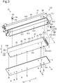
3 ist eine perspektivische Explosionsansicht einer Struktur zum Befestigen einer in 1 gezeigten Batterieeinheit. 3 FIG. 11 is an exploded perspective view of a structure for attaching an in FIG 1 shown battery unit.
-
4 ist eine perspektivische Ansicht der in 3 gezeigten Batterieeinheit. 4 is a perspective view of the in 3 shown battery unit.
-
5 ist eine perspektivische Ansicht der in 3 gezeigten Batterieeinheit in einer Richtung, die sich von der in 4 unterscheidet. 5 is a perspective view of the in 3 shown battery unit in a direction that is different from the in 4 different.
-
6 ist eine Querschnittsansicht entlang der Linie D6-D6 in 5. 6 is a cross-sectional view taken along the line D6-D6 in FIG 5 ,
-
7 ist eine perspektivische Ansicht eines Batteriebefestigungsabschnitts, der in 3 gezeigt ist. 7 FIG. 15 is a perspective view of a battery mounting portion shown in FIG 3 is shown.
-
8 ist eine perspektivische Ansicht des Batteriebefestigungsabschnitts in einer Richtung, die sich von der in 7 unterscheidet. 8th FIG. 15 is a perspective view of the battery mounting portion in a direction different from that in FIG 7 different.
-
9 ist eine Querschnittsansicht, die ein Beispiel eines Verfahrens zum Anbringen der in 3 gezeigten Batterieeinheit darstellt. 9 FIG. 12 is a cross-sectional view showing an example of a method of attaching the in. FIG 3 represents the battery unit shown.
-
10 ist eine perspektivische Explosionsansicht, die einen Zustand zeigt, in dem ein Abschnitt der Befestigungsstruktur für die in 1 gezeigte Batterieeinheit demontiert ist. 10 FIG. 16 is an exploded perspective view showing a state in which a portion of the attachment structure for the in. FIG 1 shown battery unit is dismantled.
-
11 ist eine perspektivische Ansicht, die das äußere Erscheinungsbild der Befestigungsstruktur für die in 1 gezeigte Batterieeinheit in einer Richtung zeigt, die sich von der in 10 unterscheidet. 11 is a perspective view showing the external appearance of the attachment structure for the in 1 shown battery unit in a direction which differs from the in 10 different.
-
12 ist eine perspektivische Ansicht eines in 3 gezeigten Befestigungselements. 12 is a perspective view of an in 3 shown fastener.
-
13 ist eine Querschnittsansicht entlang der Linie D13-D13 in 11. 13 is a cross-sectional view taken along the line D13-D13 in FIG 11 ,
-
14 ist eine Querschnittsansicht einer Batterieeinheit-Anordnung in einer zweiten Ausführungsform. 14 FIG. 10 is a cross-sectional view of a battery unit assembly in a second embodiment. FIG.
-
15 ist eine perspektivische Ansicht eines Befestigungselements in einer dritten Ausführungsform. 15 is a perspective view of a fastener in a third embodiment.
-
16 ist eine perspektivische Ansicht eines Befestigungselements in einer vierten Ausführungsform. 16 is a perspective view of a fastener in a fourth embodiment.
-
17 ist eine Querschnittsansicht einer Batterieeinheit-Anordnung in der vierten Ausführungsform. 17 FIG. 10 is a cross-sectional view of a battery unit assembly in the fourth embodiment. FIG.
-
18 ist eine Teilseitenansicht der Batterieeinheit-Anordnung in der vierten Ausführungsform. 18 FIG. 10 is a partial side view of the battery unit assembly in the fourth embodiment. FIG.
-
19 ist eine perspektivische Ansicht eines Befestigungselements in einer fünften Ausführungsform. 19 is a perspective view of a fastener in a fifth embodiment.
-
20 ist eine Querschnittsansicht einer Batterieeinheit-Anordnung in einer fünften Ausführungsform. 20 FIG. 10 is a cross-sectional view of a battery unit assembly in a fifth embodiment. FIG.
-
21 ist eine Querschnittsansicht einer Batterieeinheit-Anordnung in einem ersten modifizierten Beispiel. 21 FIG. 10 is a cross-sectional view of a battery unit assembly in a first modified example. FIG.
-
22 ist eine Querschnittsansicht einer Batterieeinheit-Anordnung in einem zweiten modifizierten Beispiel. 22 FIG. 10 is a cross-sectional view of a battery unit assembly in a second modified example. FIG.
-
23 ist eine Querschnittsansicht einer Batterieeinheit-Anordnung in einem dritten modifizierten Beispiel. 23 FIG. 10 is a cross-sectional view of a battery unit assembly in a third modified example. FIG.
-
24 ist eine Querschnittsansicht einer Batterieeinheit-Anordnung in einem vierten modifizierten Beispiel. 24 FIG. 10 is a cross-sectional view of a battery unit assembly in a fourth modified example. FIG.
-
25 ist eine Querschnittsansicht einer Batterieeinheit-Anordnung in einem fünften modifizierten Beispiel. 25 FIG. 10 is a cross-sectional view of a battery unit assembly in a fifth modified example. FIG.
DETAILLIERTE BESCHREIBUNG DER AUSFÜHRUNGSFORMENDETAILED DESCRIPTION OF THE EMBODIMENTS
Erste AusführungsformFirst embodiment
1 zeigt ein Fahrrad 10, das eine Batterieeinheit-Anordnung 20 aufweist. In einem Beispiel umfasst das Fahrrad 10 ferner einen Rahmen 12, eine Vorderradgabel 14, ein Vorderrad 16A, ein Hinterrad 16B und eine Lenkstange 18. Der Rahmen 12 umfasst ein Steuerrohr 12A, ein oberes Rohr 12B, ein unteres Rohr 12C, ein Sattelrohr 12E, eine Sattel strebe 12F und eine Kettenstrebe 12G. 1 shows a bicycle 10 having a battery pack assembly 20. In one example, the bicycle 10 further includes a frame 12, a front fork 14, a front wheel 16A, a rear wheel 16B, and a handlebar 18. The frame 12 includes a head tube 12A, an upper tube 12B, a lower tube 12C, a seat tube 12E, a saddle strut 12F and a chain stay 12G.
Die Batterieeinheit-Anordnung 20 umfasst ein Befestigungselement 80 und eine Fahrradbatterieeinheit 22, an der das Befestigungselement 80 befestigt ist. Die Fahrradbatterieeinheit 22 wird einfach als die Batterieeinheit 22 bezeichnet. In einem Beispiel umfasst die Batterieeinheit 20 ferner einen Batteriebefestigungsabschnitt 60. Der Batteriebefestigungsabschnitt 60 ist an dem Rahmen 12 des Fahrrads 10 vorgesehen In einem Beispiel bildet der Batteriebefestigungsabschnitt 60 einen Teil des Rahmens 12. In dem in 1 gezeigten Beispiel bildet der Batteriebefestigungsabschnitt 60 einen Teil des Unterrohrs 12C. Das Unterrohr 12C umfasst einen Kopplungsabschnitt 12D, der mit dem Steuerrohr 12A verbunden ist, und den Batteriebefestigungsabschnitt 60. In einem Beispiel ist ein Ende des Batteriebefestigungsabschnitts 60 mit dem Kopplungsabschnitt 12D verbunden, und das andere Ende des Batteriebefestigungsabschnitts 60 ist mit dem Sattelrohr 12E verbunden. Eine Antriebseinheitshalterung, an der eine Antriebseinheit angebracht ist, kann zwischen dem Batteriebefestigungsabschnitt 60 und dem Sattelrohr 12E vorgesehen sein. The battery pack assembly 20 includes a fastener 80 and a bicycle battery unit 22 to which the fastener 80 is attached. The bicycle battery unit 22 is simply referred to as the battery unit 22. In one example, the battery unit 20 further includes a battery attachment portion 60. The battery attachment portion 60 is attached to the frame 12 of the FIG In an example, the battery mounting portion 60 forms part of the frame 12. In the embodiment of FIG 1 As shown, the battery mounting portion 60 forms part of the down tube 12C. The down tube 12C includes a coupling portion 12D connected to the control tube 12A and the battery mounting portion 60. In one example, one end of the battery mounting portion 60 is connected to the coupling portion 12D, and the other end of the battery mounting portion 60 is connected to the seat tube 12E. A power unit mount to which a drive unit is attached may be provided between the battery mounting portion 60 and the seat tube 12E.
Die Antriebseinheit umfasst einen Motor, der den Antrieb des Fahrrads 10 unterstützt. Der Kopplungsabschnitt 12D kann einteilig mit dem Batteriebefestigungsabschnitt 60 als ein einstückiges Element ausgebildet sein. Alternativ kann der Kopplungsabschnitt 12D getrennt von dem Batteriebefestigungsabschnitt 60 ausgebildet sein und einteilig mit dem Batteriebefestigungsabschnitt 60 durch Schweißen oder Kleben verbunden sein. Der Batteriebefestigungsabschnitt 60 kann von dem Rahmen 12 getrennt sein.The drive unit includes a motor that supports the drive of the bicycle 10. The coupling portion 12D may be integrally formed with the battery mounting portion 60 as a one-piece member. Alternatively, the coupling portion 12D may be formed separately from the battery mounting portion 60 and integrally connected to the battery mounting portion 60 by welding or bonding. The battery mounting portion 60 may be separate from the frame 12.
Die Batterieeinheit 22 kann an dem Batteriebefestigungsabschnitt 60 angebracht sein. In einem an dem Batteriebefestigungsabschnitt 60 angebrachten Zustand ist die Batterieeinheit 22 eingerichtet, um elektrische Elemente des Fahrrads 10 mit Strom zu versorgen. Die elektrischen Elemente des Fahrrads 10 umfassen elektrische Komponenten. Die elektrischen Komponenten umfassen wenigstens eine Antriebseinheit, eine elektrische Gangschaltung, eine elektrische Federung, eine elektrische Sattelstütze, eine Anzeige, einen Fahrradcomputer, eine Lampe und eine elektrische Betätigungsvorrichtung.The battery unit 22 may be attached to the battery mounting portion 60. In a state attached to the battery mounting portion 60, the battery unit 22 is configured to supply electric power to the bicycle 10. The electrical elements of the bicycle 10 include electrical components. The electrical components include at least a power unit, an electric gearshift, an electric suspension, an electric seat post, a display, a bicycle computer, a lamp, and an electric actuator.
2 ist eine Querschnittsansicht der Batterieeinheit-Anordnung 20 entlang einer ersten Richtung X. Die Batterieeinheit 22 umfasst ein Gehäuse 24, mehrere Batteriezellen 38 und einen zweiten Eingriffsabschnitt 40. Das Gehäuse 24 nimmt die Batteriezellen 38 auf. Das Gehäuse 24 ist aus einem Harzmaterial gebildet. Das Gehäuse 24 ist quaderförmig und weist eine Abmessung in der ersten Richtung X auf, die größer als die Abmessungen in den anderen Richtungen ist. Die erste Richtung X ist die Längsrichtung des Unterrohrs 12C in einem Zustand, in dem die Batterieeinheit 22 mit dem Batteriebefestigungsabschnitt 60 verbunden ist. Das Gehäuse 24 umfasst ein Unterbringungsfach 24A. Die Batteriezellen 38 sind in dem Unterbringungsfach 24A des Gehäuses 24 untergebracht. 2 FIG. 16 is a cross-sectional view of the battery pack assembly 20 taken along a first direction X. The battery pack 22 includes a housing 24, a plurality of battery cells 38, and a second engagement portion 40. The housing 24 accommodates the battery cells 38. The housing 24 is formed of a resin material. The housing 24 is cuboid and has a dimension in the first direction X that is larger than the dimensions in the other directions. The first direction X is the longitudinal direction of the down tube 12C in a state in which the battery unit 22 is connected to the battery mounting portion 60. The housing 24 includes a storage compartment 24A. The battery cells 38 are accommodated in the accommodating compartment 24A of the housing 24.
Der Batteriebefestigungsabschnitt 60 umfasst eine Schale 62, die zumindest einen Teil der Batterieeinheit 22 aufnimmt, und einen ersten Eingriffsabschnitt 68. Die Schale 62 ist aus einem metall- oder faserverstärkten Harz gebildet. In einem Beispiel ist es bevorzugt, dass die Schale 62 aus dem gleichen Material wie der Teil des Rahmens 12 gebildet ist, mit dem die Schale 62 verbunden ist. Die Batterieeinheit 22 ist an dem Batteriebefestigungsabschnitt 60 angebracht und in der Schale 62 aufgenommen. Die Schale 62 definiert ein Unterbringungsfach 62A, das die Batterieeinheit 22 unterbringt. Der erste Eingriffsabschnitt 68 ist beispielsweise in dem Unterbringungsfach 62A vorgesehen.The battery mounting portion 60 includes a shell 62 that accommodates at least a portion of the battery unit 22 and a first engagement portion 68. The shell 62 is formed of a metal or fiber reinforced resin. In one example, it is preferable that the shell 62 is formed of the same material as the part of the frame 12 to which the shell 62 is connected. The battery unit 22 is attached to the battery mounting portion 60 and received in the tray 62. The shell 62 defines a storage compartment 62A that accommodates the battery unit 22. The first engagement portion 68 is provided in the accommodation compartment 62A, for example.
Der zweite Eingriffsabschnitt 40 der Batterieeinheit 22 ist beispielsweise einteilig mit dem Gehäuse 24 als ein einstückiges Element ausgebildet. Der zweite Eingriffsabschnitt 40 kann mit dem ersten Eingriffsabschnitt 68 des Batteriebefestigungsabschnitts 60 in Eingriff gebracht werden. Der zweite Eingriffsabschnitt 40 ist so eingerichtet, dass das Gehäuse 24 beispielsweise in einem Zustand, in dem der zweite Eingriffsabschnitt 40 mit dem ersten Eingriffsabschnitt 68 in Eingriff steht, um den ersten Eingriffsabschnitt 68 herum geschwenkt werden kann.The second engaging portion 40 of the battery unit 22 is integrally formed with the housing 24 as an integral member, for example. The second engagement portion 40 may be engaged with the first engagement portion 68 of the battery mounting portion 60. The second engagement portion 40 is configured such that the housing 24 can be pivoted about the first engagement portion 68, for example, in a state in which the second engagement portion 40 is engaged with the first engagement portion 68.
Wie in 3 gezeigt, ist die Schale 62 im Wesentlichen in Bezug auf eine Ebene, die sich entlang einer Mittellinie der Schale 62 in Bezug auf eine zweite Richtung Y erstreckt, die orthogonal zu beispielsweise der ersten Richtung X ist, symmetrisch und ist orthogonal zu der zweiten Richtung Y. Die zweite Richtung Y ist parallel zu einer Breitenrichtung, die orthogonal zu einer Vorne-Hinten-Richtung des Fahrrads 10 ist (siehe 1).As in 3 2, the shell 62 is substantially symmetrical with respect to a plane extending along a center line of the shell 62 with respect to a second direction Y which is orthogonal to, for example, the first direction X, and is orthogonal to the second direction Y. The second direction Y is parallel to a width direction orthogonal to a front-rear direction of the bicycle 10 (see FIG 1 ).
Die Schale 62 umfasst zwei Seitenwände 64A und eine Hauptwand 66. Die zwei Seitenwände 64A umfassen die Oberflächen der Schale 62, die sich in der ersten Richtung X erstrecken. Die zwei Seitenwände 64A umfassen auch die Seitenflächen der Schale 62, die sich in die zweite Richtung Y erstrecken. Die Hauptwand 66 umfasst eine Oberfläche der Schale 62, die sich in der ersten Richtung X und der zweiten Richtung Y erstreckt. Die zwei Seitenwände 64A sind mit den zwei Enden der Hauptwand 66 in der zweiten Richtung Y fortlaufend. Die Enden der zwei Seitenwände 64A und der Hauptwand 66 an der Seite des Steuerrohrs 12A (siehe 1) in der ersten Richtung X sind mit dem Verbindungsabschnitt 12D des Unterrohrs 12C verbunden. In einem Beispiel sind die zwei Seitenwände 64A und die Hauptwand 66 an der Seite des Steuerrohrs 12A in der ersten Richtung X fortlaufend mit einer Endfläche 64B, die mit dem Kopplungsabschnitt 12D des Unterrohrs 12C verbunden ist. Die zwei Seitenwände 64A sind einteilig mit der Hauptwand 66 als ein einstückiges Element ausgebildet.The shell 62 includes two side walls 64A and a main wall 66. The two side walls 64A comprise the surfaces of the shell 62 that extend in the first direction X. The two side walls 64A also include the side surfaces of the shell 62 which extend in the second direction Y. The main wall 66 includes a surface of the shell 62 extending in the first direction X and the second direction Y. The two side walls 64A are continuous with the two ends of the main wall 66 in the second direction Y. The ends of the two side walls 64A and the main wall 66 on the side of the head tube 12A (see 1 ) in the first direction X are connected to the connecting portion 12D of the down tube 12C. In one example, the two side walls 64A and the main wall 66 on the side of the head tube 12A in the first direction X are continuous with an end face 64B connected to the coupling portion 12D of the down tube 12C. The two side walls 64A are integrally formed with the main wall 66 as a one-piece member.
Die Schale 62 umfasst ferner eine erste Öffnung 64C. Die Schale 62 ist so ausgebildet, dass sich die erste Öffnung 64C beispielsweise in Richtung der unteren Seite in einem Zustand öffnet, in dem das Fahrrad 10 auf ebenem Boden steht. Die erste Öffnung 64C ist fortlaufend mit dem Unterbringungsfach 62A der Schale 62. Die erste Öffnung 64C ist so bemessen, dass die Batterieeinheit 22 in das Unterbringungsfach 62A eingesetzt werden kann. Die Batterieeinheit 22 ist durch die erste Öffnung 64C in dem Unterbringungsfach 62A zur Befestigung an dem Batteriebefestigungsabschnitt 60 aufgenommen.The shell 62 further includes a first opening 64C. The shell 62 is formed so that For example, the first opening 64C opens toward the lower side in a state where the bicycle 10 is standing on a level ground. The first opening 64C is continuous with the storage compartment 62A of the tray 62. The first opening 64C is sized so that the battery unit 22 can be inserted into the storage compartment 62A. The battery unit 22 is accommodated in the accommodation compartment 62A for attachment to the battery mounting portion 60 through the first opening 64C.
Die äußere Form der Batterieeinheit 22 ist im Wesentlichen beispielsweise zu einer Ebene plansymmetrisch, die sich entlang einer Mittellinie der Batterieeinheit 22 in Bezug auf die zweite Richtung Y erstreckt und orthogonal zu der zweiten Richtung Y ist. Die äußere Form der Batterieeinheit 22 entspricht der äußeren Form des Gehäuses 24.The outer shape of the battery unit 22 is substantially plane-symmetrical, for example, to a plane extending along a center line of the battery unit 22 with respect to the second direction Y and orthogonal to the second direction Y. The outer shape of the battery unit 22 corresponds to the outer shape of the housing 24.
Das Gehäuse 24 weist einen Umfangsabschnitt 30 mit Seitenflächen 32 auf, die sich in der ersten Richtung X erstrecken, und Endflächen 36 in Bezug auf die erste Richtung X. Die Seitenflächen 32 umfassen die Flächen des Gehäuses 24, die sich in der ersten Richtung X erstrecken. Die Seitenflächen 32 umfassen eine erste Seitenfläche 32A, eine zweite Seitenfläche 32B (siehe 4), eine dritte Seitenfläche 32C und eine vierte Seitenfläche 34. Die erste Seitenfläche 32A und die zweite Seitenfläche 32B umfassen jeweils eine Seitenfläche des Gehäuses 24 in Bezug auf die zweite Richtung Y. Die dritte Seitenfläche 32C und die vierte Seitenfläche 34 umfassen jeweils eine Seitenfläche des Gehäuses 24 in Bezug auf eine dritte Richtung Z, die orthogonal zu der ersten Richtung X und der zweiten Richtung Y ist.The housing 24 has a peripheral portion 30 with side surfaces 32 extending in the first direction X and end surfaces 36 with respect to the first direction X. The side surfaces 32 include the surfaces of the housing 24 that extend in the first direction X. , The side surfaces 32 include a first side surface 32A, a second side surface 32B (see FIG 4 The first side surface 32A and the second side surface 32B each include a side surface of the case 24 with respect to the second direction Y. The third side surface 32C and the fourth side surface 34 each include a side surface of the side surface 32C Housing 24 with respect to a third direction Z, which is orthogonal to the first direction X and the second direction Y.
Die Endflächen 36 erstrecken sich in der zweiten Richtung Y. Die Endflächen 36 umfassen eine erste Endfläche 36A und eine zweite Endfläche 36B. In einem Zustand, in dem die Batterieeinheit 22 an dem Batteriebefestigungsabschnitt 60 angebracht ist, ist die erste Endfläche 36A in einem ersten Endabschnitt 35A in der ersten Richtung X enthalten. Ferner in ist einem Zustand, in dem die Batterieeinheit 22 an dem Batteriebefestigungsabschnitt 60 angebracht ist, die zweite Endfläche 36B in einem zweiten Endabschnitt 35B in der ersten Richtung X enthalten.The end surfaces 36 extend in the second direction Y. The end surfaces 36 include a first end surface 36A and a second end surface 36B. In a state where the battery unit 22 is attached to the battery mounting portion 60, the first end surface 36A is included in a first end portion 35A in the first direction X. Further, in a state in which the battery unit 22 is attached to the battery mounting portion 60, the second end surface 36B is included in a second end portion 35B in the first direction X.
Das Gehäuse 24 umfasst einen ersten Abschnitt 26 und einen zweiten Abschnitt 28 in der ersten Richtung X. Der erste Abschnitt 26 umfasst beispielsweise die erste Endfläche 36A und Abschnitte der Seitenflächen 32, die an die erste Endfläche 36A angrenzen. Der erste Abschnitt 26 umfasst beispielsweise den Abschnitt, der sich von der Mitte des Gehäuses 24 zu einer Seite X1 hin in der ersten Richtung X erstreckt. Der zweite Abschnitt 28 umfasst beispielsweise die zweite Endfläche 36B und Abschnitte der Seitenflächen 32, die an die zweite Endfläche 36B angrenzen. Der zweite Abschnitt 28 umfasst beispielsweise den Abschnitt, der sich von der Mitte des Gehäuses 24 in der ersten Richtung X zu der anderen Seite X2 hin in der ersten Richtung X erstreckt. Der zweite Eingriffsabschnitt 40 ist an dem ersten Abschnitt 26 des Gehäuses 24 vorgesehen. Der erste Abschnitt 26 umfasst den ersten Endabschnitt 35A. Der zweite Abschnitt 28 umfasst den zweiten Endabschnitt 35B. In dem dargestellten Beispiel ist der zweite Eingriffsabschnitt 40 an der ersten Endfläche 36A des Gehäuses 24 vorgesehen.The housing 24 includes a first portion 26 and a second portion 28 in the first direction X. The first portion 26 includes, for example, the first end surface 36A and portions of the side surfaces 32 adjacent the first end surface 36A. The first portion 26 includes, for example, the portion extending from the center of the housing 24 toward a side X1 in the first direction X. The second portion 28 includes, for example, the second end surface 36B and portions of the side surfaces 32 adjacent to the second end surface 36B. The second portion 28 includes, for example, the portion extending from the center of the housing 24 in the first direction X toward the other side X2 in the first direction X. The second engagement portion 40 is provided on the first portion 26 of the housing 24. The first portion 26 includes the first end portion 35A. The second portion 28 includes the second end portion 35B. In the illustrated example, the second engagement portion 40 is provided on the first end surface 36A of the housing 24.
Die Beziehung des ersten Abschnitts 26 und des zweiten Abschnitts 28 in dem Gehäuse 24 kann in irgendeiner Weise geändert werden. In einem Beispiel kann der erste Abschnitt 26 die zweite Endfläche 36B und Abschnitte der Seitenflächen 32 angrenzend an die zweite Endfläche 36B umfassen. Der zweite Abschnitt 28 kann die erste Endfläche 36A und Abschnitte der Seitenflächen 32 umfassen, die an die erste Endfläche 36A angrenzen. In diesem Beispiel ist der zweite Eingriffsabschnitt 40 an der zweiten Endfläche 36B des Gehäuses 24 vorgesehen.The relationship of the first portion 26 and the second portion 28 in the housing 24 may be changed in any way. In one example, the first portion 26 may include the second end surface 36B and portions of the side surfaces 32 adjacent the second end surface 36B. The second portion 28 may include the first end surface 36A and portions of the side surfaces 32 adjacent the first end surface 36A. In this example, the second engagement portion 40 is provided on the second end surface 36B of the housing 24.
Die Batterieeinheit 22 umfasst ferner einen Abdeckungsbefestigungsabschnitt 42. Der Abdeckungsbefestigungsabschnitt 42 ist eingerichtet, um die Anbringung einer Abdeckung 74 zu ermöglichen. Der Abdeckungsbefestigungsabschnitt 42 ist beispielsweise an der dritten Seitenfläche 32C des Gehäuses 24 vorgesehen Der Abdeckungsbefestigungsabschnitt 42 umfasst mehrere Gewindelöcher 42A. Die Gewindelöcher 42A sind von der ersten Öffnung 64C der Schale 62 in einem Zustand freigelegt, in dem die Batterieeinheit 22 an dem Batteriebefestigungsabschnitt 60 angebracht ist. Ein Beispiel für die Anzahl der Gewindelöcher 42A ist zehn. Die Anzahl und Position der Gewindelöcher 42A kann in irgendeiner Weise geändert werden.The battery unit 22 further includes a cover fixing portion 42. The cover fixing portion 42 is configured to allow the attachment of a cover 74. The cover fixing portion 42 is provided, for example, on the third side surface 32C of the housing 24. The cover fixing portion 42 includes a plurality of threaded holes 42A. The threaded holes 42A are exposed from the first opening 64C of the shell 62 in a state in which the battery unit 22 is attached to the battery mounting portion 60. An example of the number of threaded holes 42A is ten. The number and position of the threaded holes 42A can be changed in some way.
Die Batterieeinheit-Anordnung 20 umfasst ferner die Abdeckung 74. Die Abdeckung 74 kann an der Batterieeinheit 22 angebracht und von dieser entfernt werden. Die Abdeckung 74 umfasst einen Abdeckkörper 76 und mehrere Durchgangslöcher 76A. Vorzugsweise ist der Abdeckkörper 76 eingerichtet, um die erste Öffnung 64C der Schale 62 in einem Zustand zu schließen, in dem die Batterieeinheit 22 an dem Batteriebefestigungsabschnitt 60 angebracht ist. Der Abdeckkörper 76 kann so eingerichtet sein, dass er nur einen Teil der Batterieeinheit 22 bedeckt.The battery unit assembly 20 further includes the cover 74. The cover 74 may be attached to and removed from the battery unit 22. The cover 74 includes a cover body 76 and a plurality of through holes 76A. Preferably, the cover body 76 is configured to close the first opening 64C of the shell 62 in a state where the battery unit 22 is attached to the battery mounting portion 60. The cover body 76 may be configured to cover only a part of the battery unit 22.
Die Durchgangslöcher 76A ermöglichen das Einführen von Bolzen 78. Die Durchgangslöcher 76A sind in dem Abdeckkörper 76 vorgesehen. Die Durchgangslöcher 76A sind in dem Abdeckkörper 76 an Positionen vorgesehen, die in einem Zustand, in dem der Abdeckkörper 76 an der Batterieeinheit 22 angebracht ist, den Gewindelöchern 42A entsprechen. Die Bolzen 78 sind durch die Durchgangslöcher 76A in die Gewindelöcher 42A eingesetzt, um die Abdeckung 74 an der Batterieeinheit 22 zu befestigen. In einem Zustand, in dem die Batterieeinheit 22 in dem Unterbringungsfach 62A der Schale 62 untergebracht ist, ist die Batterieeinheit 22 durch die Schale 62 und die Abdeckung 74 von außen geschützt. Die Abdeckung 74 kann nach dem Anbringen der Batterieeinheit 22 an dem Batteriebefestigungsabschnitt 60 an der Batterieeinheit 22 befestigt werden. Die Batterieeinheit 22 kann an dem Batteriebefestigungsabschnitt 60 in einem Zustand angebracht sein, in dem die Abdeckung 74 an der Batterieeinheit 22 angebracht ist. Die Abdeckung 74 und der Abdeckungsbefestigungsabschnitt 42 können aus der Batterieeinheit-Anordnung 20 weggelassen werden.The through holes 76A allow the insertion of bolts 78. The through holes 76A are provided in the cover body 76. The through holes 76A are provided in the cover body 76 at positions corresponding to the threaded holes 42A in a state where the cover body 76 is attached to the battery unit 22. The bolts 78 are inserted through the through holes 76A into the threaded holes 42A to receive the Cover 74 to be attached to the battery unit 22. In a state where the battery unit 22 is accommodated in the accommodating compartment 62A of the tray 62, the battery unit 22 is protected from the outside by the tray 62 and the cover 74. The cover 74 may be attached to the battery unit 22 after attaching the battery unit 22 to the battery mounting portion 60. The battery unit 22 may be attached to the battery mounting portion 60 in a state where the cover 74 is attached to the battery unit 22. The cover 74 and the cover fixing portion 42 may be omitted from the battery unit assembly 20.
4 zeigt die Struktur des zweiten Eingriffsabschnitts 40 der Batterieeinheit 22. 4 FIG. 14 shows the structure of the second engagement portion 40 of the battery unit 22.
Der zweite Eingriffsabschnitt 40 steht beispielsweise von der ersten Endfläche 36A des Gehäuses 24 vor. Der zweite Eingriffsabschnitt 40 ist beispielsweise in der dritten Richtung Z von der Mitte des Gehäuses 24 in Richtung der dritten Seitenfläche 32C versetzt (siehe 3). Der zweite Eingriffsabschnitt 40 kann in der dritten Richtung Z von der Mitte des Gehäuses 24 in Richtung der vierten Seitenfläche 34 versetzt sein. Der zweite Eingriffsabschnitt 40 kann beispielsweise in der Mitte des Gehäuses 24 in Bezug auf die dritte Richtung Z vorgesehen sein. Der zweite Eingriffsabschnitt 40 umfasst eine erste Nut 40A, die sich in der zweiten Richtung Y erstreckt. Die erste Nut 40A erstreckt sich beispielsweise von der ersten Seitenfläche 32A (siehe 5) zu der zweiten Seitenfläche 32B in der zweiten Richtung Y. Die erste Nut 40A öffnet sich zu der X1-Seite in der ersten Richtung X. Die erste Nut 40A öffnet sich beispielsweise an den zwei Enden in der zweiten Richtung Y. Die erste Nut 40A umfasst eine gekrümmte Innenfläche 40B und weist vorzugsweise einen allgemein U-förmigen Querschnitt in einer Richtung orthogonal zu der zweiten Richtung Y auf.The second engagement portion 40 projects, for example, from the first end surface 36A of the housing 24. The second engagement portion 40 is offset, for example, in the third direction Z from the center of the housing 24 toward the third side surface 32C (see FIG 3 ). The second engagement portion 40 may be offset in the third direction Z from the center of the housing 24 toward the fourth side surface 34. The second engagement portion 40 may be provided, for example, in the center of the housing 24 with respect to the third direction Z. The second engagement portion 40 includes a first groove 40A extending in the second direction Y. The first groove 40A extends, for example, from the first side surface 32A (see FIG 5 The first groove 40A opens to the X1 side in the first direction X. For example, the first groove 40A opens at the two ends in the second direction Y. The first groove 40A includes a curved inner surface 40B and preferably has a generally U-shaped cross section in a direction orthogonal to the second direction Y.
Die vierte Seitenfläche 34 des Gehäuses 24 umfasst beispielsweise einen gekrümmten Abschnitt. Die vierte Seitenfläche 34 umfasst eine erste geneigte Fläche 34A, eine zweite geneigte Fläche 34B und eine Zwischenfläche 34C. Die geneigten Flächen 34A und 34B sind relativ zu der Zwischenfläche 34C geneigt. Die Zwischenfläche 34C ist zwischen der ersten geneigten Fläche 34A und der zweiten geneigten Fläche 34B in der zweiten Richtung Y vorgesehen. Die erste geneigte Fläche 34A ist fortlaufend mit der ersten Seitenfläche 32A (siehe 5). Die zweite geneigte Fläche 34B ist fortlaufend mit der zweiten Seitenfläche 32B.The fourth side surface 34 of the housing 24 includes, for example, a curved portion. The fourth side surface 34 includes a first inclined surface 34A, a second inclined surface 34B, and an intermediate surface 34C. The inclined surfaces 34A and 34B are inclined relative to the intermediate surface 34C. The intermediate surface 34C is provided between the first inclined surface 34A and the second inclined surface 34B in the second direction Y. The first inclined surface 34A is continuous with the first side surface 32A (see FIG 5 ). The second inclined surface 34B is continuous with the second side surface 32B.
Wie in 5 gezeigt, umfasst die Batterieeinheit 22 elektrische Verbinder 44, eine Anzeige 46 und einen Schalter 48. Die Anzeige 46 ist eingerichtet, um beispielsweise den Batterieladezustand der Batterieeinheit 22 zu zeigen. Der Schalter 48 ist eingerichtet, um die Leistung der Batterieeinheit 22 ein- und auszuschalten. Die Anzeige 46 und der Schalter 48 sind an dem Gehäuse 24 vorgesehen. In dem dargestellten Beispiel sind die Anzeige 46 und der Schalter 48 in der vierten Seitenfläche 34 des Gehäuses 24 angeordnet. Die Batterieeinheit 22 kann ohne mindestens eines von der Anzeige 46 und dem Schalter 48 eingerichtet sein.As in 5 The battery unit 22 includes electrical connectors 44, a display 46, and a switch 48. The display 46 is configured to, for example, show the battery state of charge of the battery unit 22. The switch 48 is configured to turn on and off the power of the battery unit 22. The display 46 and the switch 48 are provided on the housing 24. In the illustrated example, the display 46 and the switch 48 are disposed in the fourth side surface 34 of the housing 24. The battery unit 22 may be configured without at least one of the display 46 and the switch 48.
Die elektrischen Verbinder 44 sind an dem Gehäuse 24 vorgesehen. Die elektrischen Verbinder 44 sind jeweils elektrisch mit einem Stecker P (siehe 11) verbindbar, der ferner elektrisch mit einer elektrischen Komponente des Fahrrads 10 verbunden ist (siehe 1). Die elektrischen Verbinder 44 umfassen einen ersten elektrischen Verbinder 44A und einen zweiten elektrischen Verbinder 44B. Der erste elektrische Verbinder 44A ist beispielsweise in der zweiten Endfläche 36B des Gehäuses 24 vorgesehen. Der zweite elektrische Verbinder 44B ist in der vierten Seitenfläche 34 des Gehäuses 24 neben der zweiten Endfläche 36B vorgesehen. Der zweite elektrische Verbinder 44B kann in der ersten Seitenfläche 32A, der zweiten Seitenfläche 32B (siehe 4) oder der dritten Seitenfläche 32C des Gehäuses 24 angrenzend an die zweite Endfläche 36B vorgesehen sein. Die Verbindung des Steckers P mit einem der elektrischen Verbinder 44A und 44B ermöglicht, dass die Batterieeinheit 22 die elektrische Komponente mit Energie versorgt. Die elektrischen Verbinder 44 können ohne den ersten elektrischen Verbinder 44A oder den zweiten elektrischen Verbinder 44B eingerichtet sein. Die elektrischen Verbinder 44 sind so eingerichtet, dass sie mit einem Ladegerät verbindbar sind, so dass die Batteriezellen über die elektrischen Verbinder 44 geladen werden können.The electrical connectors 44 are provided on the housing 24. The electrical connectors 44 are each electrically connected to a plug P (see FIG 11 ), which is further electrically connected to an electrical component of the bicycle 10 (see 1 ). The electrical connectors 44 include a first electrical connector 44A and a second electrical connector 44B. The first electrical connector 44A is provided, for example, in the second end surface 36B of the housing 24. The second electrical connector 44B is provided in the fourth side surface 34 of the housing 24 adjacent to the second end surface 36B. The second electrical connector 44B may be formed in the first side surface 32A, the second side surface 32B (see FIG 4 ) or the third side surface 32C of the housing 24 may be provided adjacent to the second end surface 36B. The connection of the plug P to one of the electrical connectors 44A and 44B allows the battery unit 22 to energize the electrical component. The electrical connectors 44 may be configured without the first electrical connector 44A or the second electrical connector 44B. The electrical connectors 44 are adapted to be connectable to a charger so that the battery cells can be charged via the electrical connectors 44.
Wie in den 2 und 6 gezeigt, sind die Batteriezellen 38 in dem Unterbringungsfach 24A des Gehäuses 24 aufgenommen. Die maximale Anzahl der Batteriezellen 38, die in dem Unterbringungsfach 24A des Gehäuses 24 aufgenommen werden können, korreliert mit dem Volumen des Unterbringungsfachs 24A. Die maximale Anzahl der Batteriezellen 38, die in dem Unterbringungsfach 24A des Gehäuses 24 aufgenommen werden können, wird im Folgenden als „die maximale Anzahl der Batteriezellen 38“ bezeichnet. Insbesondere wird die maximale Anzahl der Batteriezellen 38 durch eine erste Abmessung SX (siehe 2) in der ersten Richtung X des Gehäuses 24, eine zweite Abmessung SY (siehe 6) in der zweiten Richtung Y des Gehäuses 24 und eine dritte Abmessung SZ (siehe 6) in der dritten Richtung Z des Gehäuses 24 bestimmt. Die zweite Abmessung SY und die dritte Abmessung SZ können innerhalb eines Bereichs, der es der Batterieeinheit 22 ermöglicht, in das Aufnahmeraum 62A der Schale 62 (siehe 3) eingepasst zu sein, frei verändert werden. In einem Beispiel ermöglicht der Batteriebefestigungsabschnitt 60 das selektive Anbringen mehrerer Batterieeinheiten 22, die sich in mindestens einer von der zweiten Abmessung SY und der dritten Abmessung SZ voneinander unterscheiden und so gestaltet sind, dass sie in einem Bereich liegen, der ein Einpassen in das Unterbringungsfach 62A ermöglicht.As in the 2 and 6 As shown, the battery cells 38 are accommodated in the housing compartment 24A of the housing 24. The maximum number of battery cells 38 that can be accommodated in the housing compartment 24A of the housing 24 correlates to the volume of the housing compartment 24A. The maximum number of the battery cells 38 that can be accommodated in the housing compartment 24A of the housing 24 will be referred to hereinafter as "the maximum number of battery cells 38". In particular, the maximum number of battery cells 38 is determined by a first dimension SX (see FIG 2 ) in the first direction X of the housing 24, a second dimension SY (see 6 ) in the second direction Y of the housing 24 and a third dimension SZ (see 6 ) in the third direction Z of the housing 24. The second dimension SY and the third dimension SZ can be freely changed within a range which allows the battery unit 22 to be fitted in the accommodation space 62A of the shell 62 (see FIG. 3). In one example, the Battery mounting portion 60, the selective attachment of a plurality of battery units 22, which differ in at least one of the second dimension SY and the third dimension SZ from each other and are designed so that they are in an area that allows fitting into the housing compartment 62A.
7 zeigt den Batteriebefestigungsabschnitt 60 ohne die Batterieeinheit 22. 7 shows the battery mounting portion 60 without the battery unit 22.
Es ist bevorzugt, dass die äußere Form der Schale 62 in einer beliebigen Weise in Übereinstimmung mit dem Fahrrad 10 gestaltet ist (siehe 1). Die Schale 62 ist so ausgebildet, dass sie einen im Wesentlichen U-förmigen Querschnitt in einer Richtung orthogonal zu der ersten Richtung X aufweist. Die Hauptwand 66 umfasst eine erste geneigte Fläche 66A, eine zweite geneigte Fläche 66B, eine dritte geneigte Fläche 66C und eine Zwischenfläche 66D. Die erste geneigte Fläche 66A, die zweite geneigte Fläche 66B, die dritte geneigte Fläche 66C und die Zwischenfläche 66D sind jeweils flach. Die geneigten Flächen 66A bis 66C sind jeweils relativ zu der Zwischenfläche 66D geneigt. Die Zwischenfläche 66D ist zwischen der ersten geneigten Fläche 66A und der zweiten geneigten Fläche 66B in der zweiten Richtung Y angeordnet. Die erste geneigte Fläche 66A erstreckt sich zu einer Seite Z1 hin in der dritten Richtung Z von einem Ende der Zwischenfläche 66D in der zweiten Richtung Y und ist fortlaufend mit einer der Seitenwände 64A. Die zweite geneigte Fläche 66B erstreckt sich zu einer Seite Z1 hin in der dritten Richtung Z von dem anderen Ende der Zwischenfläche 66D in der zweiten Richtung Y und ist fortlaufend mit der anderen der Seitenwände 64A. Die dritte geneigte Fläche 66C erstreckt sich von einem Ende der Zwischenfläche 66D in der ersten Richtung X in Richtung einer Größe Z1 in der dritten Richtung Z und ist fortlaufend mit der ersten geneigten Oberfläche 66A, der zweiten geneigten Fläche 66B und der Endfläche 64B.It is preferable that the outer shape of the shell 62 is shaped in an arbitrary manner in accordance with the bicycle 10 (see FIG 1 ). The shell 62 is formed to have a substantially U-shaped cross section in a direction orthogonal to the first direction X. The main wall 66 includes a first inclined surface 66A, a second inclined surface 66B, a third inclined surface 66C, and an intermediate surface 66D. The first inclined surface 66A, the second inclined surface 66B, the third inclined surface 66C, and the intermediate surface 66D are each flat. The inclined surfaces 66A to 66C are each inclined relative to the interface 66D. The intermediate surface 66D is disposed between the first inclined surface 66A and the second inclined surface 66B in the second direction Y. The first inclined surface 66A extends toward a side Z1 in the third direction Z from one end of the intermediate surface 66D in the second direction Y and is continuous with one of the side walls 64A. The second inclined surface 66B extends toward a side Z1 in the third direction Z from the other end of the interface 66D in the second direction Y and is continuous with the other of the side walls 64A. The third inclined surface 66C extends from an end of the intermediate surface 66D in the first direction X toward a size Z1 in the third direction Z and is continuous with the first inclined surface 66A, the second inclined surface 66B and the end surface 64B.
Der Batteriebefestigungsabschnitt 60 umfasst ferner eine zweite Öffnung 66E. Der zweite elektrische Verbinder 44B, die Anzeige 46 und der Schalter 48 sind von der zweiten Öffnung 66E (siehe 11) in einem Zustand freigelegt, in dem die Batterieeinheit 22 an dem Batteriebefestigungsabschnitt 60 angebracht ist. Die zweite Öffnung 66E ist beispielsweise in der Hauptwand 66 der Schale 62 vorgesehen. In einem Beispiel ist die zweite Öffnung 66E in der Zwischenfläche 66D der Hauptwand 66 vorgesehen. Die Position der zweiten Öffnung 66E in der Schale 62 wird durch das Layout des zweiten elektrischen Verbinders 44B, der Anzeige 46 und des Schalters 48 bestimmt, die an der Batterieeinheit vorgesehen sind. Beispielsweise ist in einem Fall, in dem der zweite elektrische Verbinder 44B, die Anzeige 46 und der Schalter 48 an einer der ersten Seitenfläche 32A und der zweiten Seitenfläche 32B der Batterieeinheit 22 vorgesehen sind, die zweite Öffnung 66E in der entsprechenden einen von den Seitenflächen 32A und 32B der Schale 62 vorgesehen. Die zweite Öffnung 66E kann für jeden von dem zweiten elektrischen Verbinder 44B, der Anzeige 46 und dem Schalter 48 vorgesehen sein. Der Batteriebefestigungsabschnitt 60 kann ohne die zweite Öffnung 66E eingerichtet sein.The battery mounting portion 60 further includes a second opening 66E. The second electrical connector 44B, the indicator 46 and the switch 48 are from the second opening 66E (see 11 ) is exposed in a state in which the battery unit 22 is attached to the battery mounting portion 60. The second opening 66E is provided, for example, in the main wall 66 of the shell 62. In one example, the second opening 66E is provided in the interface 66D of the main wall 66. The position of the second opening 66E in the shell 62 is determined by the layout of the second electrical connector 44B, the indicator 46, and the switch 48 provided on the battery pack. For example, in a case where the second electrical connector 44B, the indicator 46 and the switch 48 are provided on one of the first side surface 32A and the second side surface 32B of the battery unit 22, the second opening 66E is in the corresponding one of the side surfaces 32A and 32B of the shell 62. The second opening 66E may be provided for each of the second electrical connector 44B, the indicator 46, and the switch 48. The battery mounting portion 60 may be configured without the second opening 66E.
8 zeigt die Struktur des ersten Eingriffsabschnitts 68 des Batteriebefestigungsabschnitts 60. 8th FIG. 14 shows the structure of the first engagement portion 68 of the battery mounting portion 60.
Der erste Eingriffsabschnitt 68 umfasst beispielsweise einen Vorsprung, der in die erste Nut 40A des zweiten Eingriffsabschnitts 40 eingepasst ist (siehe 4). Vorzugsweise berührt der Vorsprung in einem Zustand, in dem der Vorsprung in die erste Nut 40A eingepasst ist, den zweiten Eingriffsabschnitt 40 zumindest an zwei Orten, die in der zweiten Richtung Y beabstandet sind. Der Vorsprung des ersten Eingriffsabschnitts 68 umfasst eine Stange 68A. Vorzugsweise ist die Stange 68A zylindrisch. Die Stange 68A des ersten Eingriffsabschnitts 68 erstreckt sich in der zweiten Richtung Y in dem Unterbringungsfach 62A der Schale 62. Der erste Eingriffsabschnitt 68 kann als ein Element der Batterieeinheit-Anordnung 20 eingerichtet sein.The first engagement portion 68 includes, for example, a protrusion fitted in the first groove 40A of the second engagement portion 40 (see FIG 4 ). Preferably, in a state in which the protrusion is fitted in the first groove 40A, the protrusion contacts the second engagement portion 40 at least at two locations spaced in the second direction Y. The projection of the first engagement portion 68 includes a rod 68A. Preferably, the rod 68A is cylindrical. The rod 68A of the first engagement portion 68 extends in the second direction Y in the accommodation compartment 62A of the shell 62. The first engagement portion 68 may be configured as an element of the battery unit assembly 20.
Die erste Nut 40A weist eine Tiefe in der ersten Richtung X auf, die größer ist als der Durchmesser der Stange 68A des ersten Eingriffsabschnitts 68. Dies beschränkt die Trennung des zweiten Eingriffsabschnitts 40 von dem ersten Eingriffsabschnitt 68, wenn sich die Batterieeinheit 22 in der ersten Richtung X in einem Zustand bewegt, in dem der zweite Eingriffsabschnitt 40 mit dem ersten Eingriffsabschnitt 68 in Eingriff steht. Die erste Nut 40A weist eine Abmessung in der dritten Richtung Z auf, die im Wesentlichen die gleiche ist wie der Durchmesser der Stange 68A des ersten Eingriffsabschnitt 68 oder geringfügig größer als der Durchmesser der Stange 68A. In einem Zustand, in dem der erste Eingriffsabschnitt 68 und der zweite Eingriffsabschnitt 40 in Eingriff sind, kann ein elastisches Element an oder in mindestens einem von dem ersten Eingriffsabschnitt 68 und dem zweiten Eingriffsabschnitt 40 angeordnet sein, um zwischen dem ersten Eingriffsabschnitt 68 und dem zweiten Eingriffsabschnitt 40 angeordnet zu sein. Das elastische Element umfasst zum Beispiel Gummi oder Urethan. Die erste Nut 40A öffnet sich in der dritten Richtung Z zu einer Seite Z1 hin.The first groove 40A has a depth in the first direction X that is greater than the diameter of the rod 68A of the first engagement portion 68. This limits the separation of the second engagement portion 40 from the first engagement portion 68 when the battery unit 22 in the first Direction X moves in a state in which the second engagement portion 40 is engaged with the first engagement portion 68. The first groove 40A has a dimension in the third direction Z which is substantially the same as the diameter of the rod 68A of the first engagement portion 68 or slightly larger than the diameter of the rod 68A. In a state in which the first engagement portion 68 and the second engagement portion 40 are engaged, an elastic member may be disposed on or in at least one of the first engagement portion 68 and the second engagement portion 40 so as to be between the first engagement portion 68 and the second Engagement portion 40 to be arranged. The elastic member includes, for example, rubber or urethane. The first groove 40A opens in the third direction Z toward a side Z1.
Der Batteriebefestigungsabschnitt 60 umfasst ferner zwei Stützlöcher 72. Die zwei Stützlöcher 72 ermöglichen das Einführen der Stange 68A des ersten Eingriffsabschnitts 68. Die zwei Stützlöcher 72 sind beispielsweise in Abschnitten vorgesehen, die einander zugewandt sind, in den zwei Seitenwänden 64A der Schale 62. Die erste Nut 40A weist vorzugsweise eine Breite in der zweiten Richtung Y auf, die im Wesentlichen die gleiche wie eine axiale Abmessung eines Abschnitts der Stange 68A ist, die in dem Unterbringungsfach 62A angeordnet ist. Die Stützlöcher 72 erstrecken sich durch die Seitenwände 64A in der zweiten Richtung Y. Die Stange 68A des ersten Eingriffsabschnitts 68 umfasst zum Beispiel ein Ende 69A in der axialen Richtung, das einen Gewindeabschnitt 68B definiert (siehe 3). Die Oberfläche in der Seitenwand 64A einschließlich des einen von den Stützlöchern 72, das dem Gewindeabschnitt 68B des ersten Eingriffsabschnitts 68 entspricht, ist mit einem Gewinde (nicht gezeigt) versehen und kann mit dem Gewindeabschnitt 68B des ersten Eingriffsabschnitts 68 verbunden werden. Die Stange 68A des ersten Eingriffsabschnitts 68 umfasst beispielsweise ein anderes Ende 69B in der axialen Richtung und einen Flansch 68C, der sich von dem Ende 69B erstreckt und einen größeren Durchmesser aufweist als die Stützlöcher 72. Der Flansch 68C berührt den Batteriebefestigungsabschnitt 60 von einer äußeren Seite und positioniert die Stange 68A des ersten Eingriffsabschnitts 68 in der zweiten Richtung Y.The battery mounting portion 60 further includes two support holes 72. The two support holes 72 allow the insertion of the rod 68A of the first engagement portion 68. The two support holes 72 are provided, for example, in portions facing each other in the two side walls 64A of the shell 62. The first Groove 40A points Preferably, a width in the second direction Y, which is substantially the same as an axial dimension of a portion of the rod 68A, which is disposed in the accommodation compartment 62A. The support holes 72 extend through the side walls 64A in the second direction Y. The rod 68A of the first engagement portion 68 includes, for example, an end 69A in the axial direction that defines a threaded portion 68B (see FIG 3 ). The surface in the side wall 64A including the one of the support holes 72 corresponding to the threaded portion 68B of the first engagement portion 68 is threaded (not shown) and may be connected to the threaded portion 68B of the first engagement portion 68. The rod 68A of the first engagement portion 68 includes, for example, another end 69B in the axial direction and a flange 68C extending from the end 69B and larger in diameter than the support holes 72. The flange 68C contacts the battery mounting portion 60 from an outer side and positions the rod 68A of the first engagement portion 68 in the second direction Y.
Ein Ende 69A der Stange 68A des ersten Eingriffsabschnitts 68 wird von einem der Stützlöcher 72 gestützt. Das andere Ende 69B der Stange 68A des ersten Eingriffsabschnitts 68 wird durch das andere der Stützlöcher 72 gestützt. Das andere Ende 69B oder der Flansch 68C der Stange 68A des ersten Eingriffsabschnitts 68 weist vorzugsweise einen Eingriffsabschnitt auf, der mit einem Werkzeug in Eingriff gebracht werden kann, das verwendet wird, um die Stange 68A um ihre Achse herum zu drehen. Die Stange 68A des ersten Eingriffsabschnitts 68 wird in die zwei Stützöffnungen 72 in der zweiten Richtung Y eingesetzt, und der Gewindeabschnitt 68B wird mit dem Gewindeabschnitt eines der Stützlöcher 72 verbunden, um die Stange 68A an der Schale 62 zu befestigen. Vorzugsweise ist die Stange 68A des ersten Eingriffsabschnitts 68 durch Stauchen, Kleben, Schweißen oder dergleichen in einer nicht abnehmbaren Weise an der Schale 62 befestigt.One end 69A of the rod 68A of the first engagement portion 68 is supported by one of the support holes 72. The other end 69B of the rod 68A of the first engagement portion 68 is supported by the other one of the support holes 72. The other end 69B or the flange 68C of the rod 68A of the first engagement portion 68 preferably has an engagement portion that can be engaged with a tool used to rotate the rod 68A about its axis. The rod 68A of the first engagement portion 68 is inserted into the two support openings 72 in the second direction Y, and the threaded portion 68B is connected to the threaded portion of one of the support holes 72 to fix the rod 68A to the shell 62. Preferably, the rod 68A of the first engagement portion 68 is fixed to the shell 62 in a non-detachable manner by swaging, gluing, welding or the like.
Die Stange 68A des ersten Eingriffsabschnitts 68 kann ohne mindestens einen von dem Gewindeabschnitt 68B und dem Flansch 68C eingerichtet sein. In einem Fall, in dem die Stange 68A des ersten Eingriffsabschnitts 68 den Gewindeabschnitt 68B nicht umfasst, kann das Ende 69A der Stange 68A des ersten Eingriffsabschnitts 68 in eines der Stützlöcher 72 eingepresst und an dem Batteriebefestigungsabschnitt 60 fixiert sein. Alternativ kann das Ende 69A in einem in den Stützlöchern 72 eingesetzten Zustand an dem Batteriebefestigungsabschnitt 60 angeklebt oder angeschweißt und fixiert sein. Das andere Ende 69B der Stange 68A des ersten Eingriffsabschnitts 68 kann in das andere der Stützlöcher 72 eingepresst sein und an dem Batteriebefestigungsabschnitt 60 fixiert sein. Alternativ dazu kann das Ende 69B in einem in das andere der Halterungslöcher 72 eingesetzten Zustand an dem Batteriebefestigungsabschnitt 60 angeklebt oder angeschweißt und an diesem fixiert werden. In dem veranschaulichten Beispiel ist die Stange 68A des ersten Eingriffsabschnitts 68 so eingerichtet, dass sie in einem in die Stützlöcher 72 eingesetzten Zustand nicht aus den Seitenwänden 64A der Schale 62 vorsteht. Eines der Stützlöcher 72 kann durch ein Sackloch eingerichtet sein, das mit dem Unterbringungsfach 62A fortlaufend ist.The rod 68A of the first engagement portion 68 may be configured without at least one of the threaded portion 68B and the flange 68C. In a case where the rod 68A of the first engagement portion 68 does not include the threaded portion 68B, the end 69A of the rod 68A of the first engagement portion 68 may be press-fitted into one of the support holes 72 and fixed to the battery mounting portion 60. Alternatively, the end 69A may be adhered or welded and fixed to the battery mounting portion 60 in a state inserted in the support holes 72. The other end 69B of the rod 68A of the first engagement portion 68 may be press-fitted into the other one of the support holes 72 and fixed to the battery mounting portion 60. Alternatively, the end 69B may be adhered or welded to and fixed to the battery mounting portion 60 in a state inserted into the other one of the mounting holes 72. In the illustrated example, the rod 68A of the first engagement portion 68 is configured so that it does not protrude from the side walls 64A of the shell 62 in a state inserted into the support holes 72. One of the support holes 72 may be configured by a blind hole that is continuous with the storage compartment 62A.
Das Gehäuse 24 der Batterieeinheit 22 umfasst einen zweiten Gewindeabschnitt 52, der zum Anbringen des Befestigungselements 80 verwendet wird. Das Gehäuse 24 umfasst einen ersten Gehäuseabschnitt 50. Der zweite Gewindeabschnitt 52 ist in dem ersten Gehäuseabschnitt 50 enthalten. Der erste Gehäuseabschnitt 50 ist durch den Abschnitt des Gehäuses 24 definiert, der die Zwischenfläche 34C bildet. Der zweite Gewindeabschnitt 52 umfasst ein Gewindeloch 52A, das sich durch den ersten Gehäuseabschnitt 50 in der dritten Richtung Z erstreckt. Der Batteriebefestigungsabschnitt 60, der an dem Rahmen 12 vorgesehen ist, umfasst ferner einen ersten Rahmenabschnitt 70. Der erste Rahmenabschnitt 70 ist durch die Hauptwand 66 definiert. Der erste Rahmenabschnitt 70 umfasst ein Loch 70A, durch das das Befestigungselement 80 eingesetzt wird. Das Loch 70A ermöglicht das Einführen des Befestigungselements 80. Das Loch 70A ist in der Schale 62 an einer Position vorgesehen, die dem zweiten Gewindeabschnitt 52 des ersten Gehäuseabschnitts 50 in einem Zustand entspricht, in dem die Batterieeinheit 22 dem Aufnahmeraum 62A der Schale 62 aufgenommen ist. Das Loch 70A erstreckt sich durch die Hauptwand 66 in der dritten Richtung Z. Das Gewindeloch 52A muss sich nicht durch den ersten Gehäuseabschnitt 50 erstrecken. In einem solchen Fall weist der erste Gehäuseabschnitt 50 zum Beispiel eine Nut auf, und das Gewindeloch 52A ist an der offenen Seite der Nut ausgebildet. Vorzugsweise hat der Raum nahe dem Boden der Nut auf der gegenüberliegenden Seite der Öffnung einen größeren Durchmesser als das Gewindeloch 52A. In diesem Fall kann die Nut einen Durchmesser aufweisen, der von der Öffnung in Richtung des Bodens in dem Gehäuse 24 fixiert ist, und ein Element, das das Gewindeloch 52A umfasst, kann an der Nut angebracht sein, um den ersten Gehäuseabschnitt 50 zu bilden.The housing 24 of the battery unit 22 includes a second threaded portion 52 for attaching the fastener 80 is used. The housing 24 includes a first housing portion 50 , The second threaded portion 52 is in the first housing portion 50 contain. The first housing section 50 is defined by the portion of the housing 24 that forms the interface 34C. The second threaded portion 52 includes a threaded hole 52A extending through the first housing portion 50 extends in the third direction Z. The battery mounting portion 60 provided on the frame 12 further includes a first frame portion 70 , The first frame section 70 is defined by the main wall 66. The first frame section 70 includes a hole 70A through which the fastener 80 is used. The hole 70A allows the insertion of the fastener 80 , The hole 70A is provided in the shell 62 at a position corresponding to the second threaded portion 52 of the first housing portion 50 in a state where the battery unit 22 is received in the receiving space 62A of the tray 62. The hole 70A extends through the main wall 66 in the third direction Z. The threaded hole 52A need not pass through the first housing section 50 extend. In such a case, the first housing section 50 for example, a groove, and the threaded hole 52A is formed on the open side of the groove. Preferably, the space near the bottom of the groove on the opposite side of the opening has a larger diameter than the threaded hole 52A. In this case, the groove may have a diameter fixed from the opening toward the bottom in the housing 24, and a member including the threaded hole 52A may be attached to the groove around the first housing portion 50 to build.
Wie in den 12 und 13 gezeigt, wird das Befestigungselement 80 verwendet, um die Batterieeinheit 22 an dem Rahmen 12 des Fahrrads 10 zu befestigen. Das Befestigungselement 80 umfasst ein Kopplungselement 82 und eine Verriegelungseinheit 84. Das Befestigungselement 80 umfasst ferner einen Eingriffsabschnitt 86.As in the 12 and 13 shown, the fastener 80 used to attach the battery unit 22 to the frame 12 of the bicycle 10. The fastener 80 comprises a coupling element 82 and a locking unit 84 , The fastener 80 further includes an engagement portion 86.
Das Kopplungselement 82 umfasst eine erste Stange 88. Die erste Stange 88 umfasst einen Außenumfang 90 und einen ersten Gewindeabschnitt 92, der durch mindestens einen Teil des Außenumfangs 90 definiert ist. In einem Zustand, in dem die Batterieeinheit 22 in dem Rahmen 12 angeordnet ist, ist das Kopplungselement 82 durch den ersten Rahmenabschnitt 70 des Rahmens 12 hindurch eingesetzt und mit dem ersten Gehäuseabschnitt 50 verbunden, um die Bewegung der Batterieeinheit 22 relativ zu dem Rahmen 12 zu beschränken. Der erste Gewindeabschnitt 92 ist mit dem zweiten Gewindeabschnitt 52 in dem ersten Gehäuseabschnitt 50 verbunden, so dass das Kopplungselement 82 die Bewegung der Batterieeinheit 22 relativ zu dem Rahmen 12 beschränkt. Der erste Gewindeabschnitt 92 ist in einem axial mittleren Abschnitt der ersten Stange 88 vorgesehen. Der erste Gewindeabschnitt 92 kann sich in der axialen Richtung über die gesamte erste Stange 88 erstrecken, mit Ausnahme eines Bereichs, der einen Beschränkungsabschnitt 94 definiert. Alternativ kann sich der erste Gewindeabschnitt 92 in axialer Richtung über die gesamte erste Stange 88 hinaus erstrecken, mit Ausnahme von Bereichen, die den Beschränkungsabschnitt 94 und einen beweglichen Abschnitt 96 der Verriegelungseinheit 84 umfassen. In der vorliegenden Ausführungsform erstreckt sich der erste Gewindeabschnitt 92 über die erste Stange 88 in der axialen Richtung in Bereichen außer einem ersten Ende 88A, das an der Seite der ersten Stange 88 gegenüber dem Beschränkungsabschnitt 94 angeordnet ist, und einem zu dem Beschränkungsabschnitt 94 benachbarten Abschnitt. In einem Fall, in dem sich die Gewindebohrung 52A des ersten Gehäuseabschnitts 50 nicht durch den ersten Gehäuseabschnitt 50 hindurch erstreckt und als eine Aussparung in dem ersten Gehäuseabschnitt 50 ausgebildet ist, ist das erste Ende 88A der ersten Stange 88 in einem Raum aufgenommen, der sich in Richtung des Bodens der Aussparung auf der Seite gegenüber der Öffnung der Aussparung befindet. The coupling element 82 includes a first pole 88 , The first pole 88 includes an outer periphery 90 and a first threaded portion 92 passing through at least part of the outer circumference 90 is defined. In a state where the battery unit 22 is disposed in the frame 12, the coupling member is 82 through the first frame section 70 the frame 12 inserted through and with the first housing portion 50 connected to restrict the movement of the battery unit 22 relative to the frame 12. The first threaded section 92 is with the second threaded portion 52 in the first housing portion 50 connected so that the coupling element 82 limits the movement of the battery unit 22 relative to the frame 12. The first threaded section 92 is in an axially middle section of the first rod 88 intended. The first threaded section 92 may extend in the axial direction over the entire first rod 88, except for a portion having a restriction portion 94 Are defined. Alternatively, the first threaded portion 92 in the axial direction over the entire first rod 88 extend beyond the restricting section except for areas 94 and a moving section 96 the locking unit 84 include. In the present embodiment, the first threaded portion extends 92 over the first pole 88 in the axial direction in areas other than a first end 88A that is on the side of the first bar 88 opposite the restriction section 94 is arranged, and one to the restriction section 94 adjacent section. In a case where the threaded hole 52A of the first housing portion 50 not through the first housing section 50 extends through and as a recess in the first housing portion 50 is formed, the first end 88A of the first rod 88 accommodated in a space located towards the bottom of the recess on the side opposite the opening of the recess.
Das Kopplungselement 82 umfasst ferner den Beschränkungsabschnitt 94, der den ersten Rahmenabschnitt 70 berührt und die Bewegung der ersten Stange 88 zu einer Seite in der axialen Richtung beschränkt. Der Beschränkungsabschnitt 94 ist an einem axialen Ende der ersten Stange 88 vorgesehen. Der Beschränkungsabschnitt 94 erstreckt sich von dem Außenumfang 90 der ersten Stange 88 in der radialen Richtung der ersten Stange 88. Der Beschränkungsabschnitt 94 weist einen größeren Außendurchmesser auf als die erste Stange 88. Der Außendurchmesser des Beschränkungsabschnitts 94 ist größer als der Innendurchmesser des Lochs 70A in dem ersten Rahmenabschnitt 70. Somit beschränkt der Kontakt des Beschränkungsabschnitts 94 mit der Oberfläche um das Loch 70A herum eine Bewegung des Beschränkungsabschnitts 94 in Richtung des Unterbringungsfachs 24A hin.The coupling element 82 further comprises the restriction section 94 which is the first frame section 70 touched and the movement of the first rod 88 limited to one side in the axial direction. The restriction section 94 is at an axial end of the first rod 88 intended. The restriction section 94 extends from the outer periphery 90 the first pole 88 in the radial direction of the first rod 88 , The restriction section 94 has a larger outer diameter than the first rod 88 , The outer diameter of the restriction portion 94 is larger than the inner diameter of the hole 70A in the first frame section 70 , Thus, the contact of the restriction section restricts 94 with the surface around the hole 70A around a movement of the restricting section 94 towards the storage compartment 24A.
Der Eingriffsabschnitt 86 ist an dem Beschränkungsabschnitt 94 vorgesehen und kann mit einem Werkzeug (nicht gezeigt) in Eingriff gebracht werden, das zum Drehen des ersten Gewindeabschnitts 92 verwendet wird. In einem Beispiel umfasst der Eingriffsabschnitt 86 einen durch den äußeren Teil des Beschränkungsabschnitts 94 gebildeten polygonalen Bolzenkopf 94. In diesem Fall umfasst das Werkzeug einen Schraubenschlüssel oder einen Maulschlüssel. Man verwendet das Werkzeug, um den ersten Gewindeabschnitt 92 an dem zweiten Gewindeabschnitt 52 zu befestigen und die Batterieeinheit 22 an dem Rahmen 12 mit dem Kopplungselement 82 zu befestigen. Das Kopplungselement 82 beschränkt die relative Bewegung des Rahmens 12 und der Batterieeinheit 22.The engaging portion 86 is at the restricting portion 94 is provided and can be brought into engagement with a tool (not shown), which is for rotating the first threaded portion 92 is used. In one example, the engagement portion 86 includes one through the outer portion of the restriction portion 94 formed polygonal bolt head 94 , In this case, the tool includes a wrench or a spanner. The tool is used to secure the first threaded portion 92 to the second threaded portion 52 and the battery unit 22 to the frame 12 to the coupling member 82 to fix. The coupling element 82 limits the relative movement of the frame 12 and the battery unit 22.
Die Verriegelungseinheit 84 ist an dem Kopplungselement 82 vorgesehen. Die Verriegelungseinheit 84 ist an der ersten Stange 88 vorgesehen. Die Verriegelungseinheit 84 umfasst den beweglichen Abschnitt 96, eine Einführungsöffnung 98 und einen Schlüsselzylinder 100. Die Verriegelungseinheit 84 ist zwischen einem Beschränkungszustand, in dem die Verriegelungseinheit 84 die Bewegung des Kopplungselements 82 relativ zu dem Gehäuse 24 und dem Rahmen 12 beschränkt ist, und einem Freigabezustand, in dem die Verriegelungseinheit 84 eine Bewegung des Kopplungselements 82 relativ zu dem Gehäuse 24 und dem Rahmen 12 ermöglicht, umschaltbar.The locking unit 84 is on the coupling element 82 intended. The locking unit 84 is at the first pole 88 intended. The locking unit 84 includes the movable portion 96 , an insertion opening 98 and a key cylinder 100. The locking unit 84 is between a restriction state in which the locking unit 84 the movement of the coupling element 82 is limited relative to the housing 24 and the frame 12, and a release state in which the locking unit 84 a movement of the coupling element 82 relative to the housing 24 and the frame 12, switchable.
Der bewegliche Abschnitt 96, der an der ersten Stange 88 vorgesehen ist, kann aus der Außenumfangsfläche 90A der ersten Stange 88 herausragen. Der bewegliche Abschnitt 96 ist zwischen einer ersten Position P1, in der der bewegliche Abschnitt 96 in dem Beschränkungszustand mindestens einen von dem Rahmen 12 und der Batterieeinheit 22 von der anderen Seite in der axialen Richtung berühren kann, und einer zweiten Position P2, in der der bewegliche Abschnitt 96 in dem Freigabezustand den Rahmen 12 und die Batterieeinheit 22 von der anderen Seite in axialer Richtung nicht berühren kann, bewegbar. Der bewegliche Abschnitt 96, der an der ersten Stange 88 vorgesehen ist, ist zwischen der ersten Position P1, an der der bewegliche Abschnitt 96 in der Radialrichtung der ersten Stange 88 von dem Außenumfang 90 der ersten Stange 88 nach außen vorsteht, und der zweiten Position P2, in der der bewegliche Abschnitt 96 von der ersten Position P1 in Richtung des Außenumfangs 90 der ersten Stange 88 eingezogen ist, bewegbar. Der bewegliche Abschnitt 96, der durch die durchgezogenen Linien in den 12 und 13 gezeigt ist, befindet sich an der zweiten Position P2. Der bewegliche Abschnitt 96, der durch die doppelt gestrichelten Linien in den 12 und 13 gezeigt ist, befindet sich in der ersten Position P1. Die Verriegelungseinheit 84 bewegt den beweglichen Abschnitt 96 zwischen der ersten Position P1 und der zweiten Position P2.The moving section 96 who is at the first pole 88 may be provided from the outer peripheral surface 90A of the first rod 88 protrude. The moving section 96 is between a first position P1, in which the movable portion 96 in the restricted state, at least one of the frame 12 and the battery unit 22 can touch from the other side in the axial direction, and a second position P2 in which the movable portion 96 in the release state, the frame 12 and the battery unit 22 can not touch from the other side in the axial direction, movable. The moving section 96 who is at the first pole 88 is provided is between the first position P1, at which the movable portion 96 in the radial direction of the first rod 88 from the outer circumference 90 the first pole 88 protrudes outward, and the second position P2, in which the movable section 96 from the first position P1 toward the outer circumference 90 the first pole 88 retracted, movable. The moving section 96 which is indicated by the solid lines in the 12 and 13 is shown is located at the second position P2. The moving section 96 which is indicated by the double-dashed lines in the 12 and 13 is shown is in the first position P1. The locking unit 84 move that movable section 96 between the first position P1 and the second position P2.
In einem Fall, in dem sich der bewegliche Abschnitt 96 in der ersten Position P1 befindet, steht der bewegliche Abschnitt 96 aus der Außenumfangsfläche 90A der ersten Stange 88 vor. In einem Fall, in dem der bewegliche Abschnitt 96 in der zweiten Position P2 angeordnet ist, steht der bewegliche Abschnitt 96 nicht von der Außenumfangsfläche 90A der ersten Stange 88 vor. In einem weiteren Beispiel ist der Vorsprungsbetrag des beweglichen Abschnitts 96 von der Außenumfangsfläche 90A der ersten Stange 88 in einem Fall, in dem der bewegliche Abschnitt 96 an der zweiten Position P2 angeordnet ist, kleiner als der Vorsprungsbetrag des beweglichen Abschnitts 96 von der Außenumfangsoberfläche 90A der ersten Stange 88 in einem Fall, in dem sich der bewegliche Abschnitt 96 in der ersten Position P1 befindet. In diesem Fall weisen das Loch 70A des ersten Rahmenabschnitts 70 und der zweite Gewindeabschnitt 52 des ersten Gehäuseabschnitts 50 jeweils einen Innendurchmesser auf, der es dem beweglichen Abschnitt 96 ermöglicht, sich in der zweiten Position P2 zu bewegen.In a case where the moving section 96 is in the first position P1, is the movable section 96 from the outer peripheral surface 90A of the first rod 88 in front. In a case where the moving section 96 is disposed in the second position P2, is the movable portion 96 not from the outer peripheral surface 90A of the first rod 88 in front. In another example, the protrusion amount of the movable portion 96 from the outer peripheral surface 90A of the first rod 88 in a case where the moving section 96 is disposed at the second position P2, smaller than the protrusion amount of the movable portion 96 from the outer peripheral surface 90A of the first rod 88 in a case where the movable portion 96 is in the first position P1. In this case, point the hole 70A of the first frame section 70 and the second threaded portion 52 of the first housing portion 50 each having an inner diameter, which is the movable portion 96 allows to move in the second position P2.
In einem Fall, in dem der bewegliche Abschnitt 96 in der zweiten Position P2 in einem Zustand angeordnet ist, in dem das Kopplungselement 82 in das Loch 70A des ersten Rahmenabschnitts 70 und das Gewindeloch 52A des ersten Gehäuseabschnitts 50 eingesetzt ist, ist der maximale Außendurchmesser, in dem der bewegliche Abschnitt 96 angeordnet ist, kleiner als der minimale Innendurchmesser von jedem von dem Loch 70A des ersten Rahmenabschnitts 70 und dem Gewindeloch 52A des ersten Gehäuseabschnitts 50. Somit kann sich in einem Fall, in dem auf das Befestigungselement 80 von dem ersten Gehäuseabschnitt 50 in Richtung des ersten Rahmenabschnitts 70 Kraft ausgeübt wird, das Kopplungselement 82 von dem Rahmen 12 nach außen bewegen, ohne dass der bewegliche Abschnitt 96 die Innenfläche des ersten Gehäuseabschnitts 50 berührt. In einem Fall, in dem der bewegliche Abschnitt 96 in der ersten Position P1 in einem Zustand angeordnet ist, in dem das Kopplungselement 82 in das Loch 70A des ersten Rahmenabschnitts 70 und das Gewindeloch 52A des ersten Gehäuseabschnitts 50 eingesetzt ist, ist der maximale Außendurchmesser, in dem der bewegliche Abschnitt 96 angeordnet ist, größer als der minimale Innendurchmesser jedes von dem Loch 70A des ersten Rahmenabschnitts 70 und dem Gewindeloch 52A des ersten Gehäuseabschnitts 50. Somit beschränkt in einem Fall, in dem auf das Befestigungselement 80 von dem ersten Gehäuseabschnitt 50 in Richtung des ersten Rahmenabschnitts 70 Kraft ausgeübt wird, der Kontakt des beweglichen Abschnitts 96 und des ersten Gehäuseabschnitts 50 die Auswärtsbewegung des Befestigungselements 80 von dem Rahmen 12.In a case where the moving section 96 is disposed in the second position P2 in a state in which the coupling element 82 in the hole 70A of the first frame section 70 and the threaded hole 52A of the first housing portion 50 is inserted, is the maximum outer diameter, in which the movable section 96 is arranged smaller than the minimum inner diameter of each of the hole 70A of the first frame section 70 and the threaded hole 52A of the first housing portion 50 , Thus, in a case in which the fastener 80 from the first housing section 50 in the direction of the first frame section 70 Force is exercised, the coupling element 82 move outwardly from the frame 12 without the movable portion 96 the inner surface of the first housing portion 50 touched. In a case where the moving section 96 is disposed in the first position P1 in a state in which the coupling element 82 in the hole 70A of the first frame section 70 and the threaded hole 52A of the first housing portion 50 is inserted, is the maximum outer diameter, in which the movable section 96 is arranged larger than the minimum inner diameter of each of the hole 70A of the first frame section 70 and the threaded hole 52A of the first housing portion 50 , Thus, in a case where limited to the fastener 80 from the first housing section 50 in the direction of the first frame section 70 Force is exercised, the contact of the movable section 96 and the first housing section 50 the outward movement of the fastener 80 from the frame 12.
Die Einführungsöffnung 98 ist von der Endfläche des Beschränkungsabschnitts 94 freigelegt und ermöglicht das Einführen eines Schlüssels (nicht gezeigt). Die Einführungsöffnung 98 ist mit dem Schlüsselzylinder 100 verbunden. Der Schlüsselzylinder 100 wird durch einen Schlüssel betätigt, um den beweglichen Abschnitt 96 zu bewegen. Der Schlüssel wird in die Einführungsöffnung 98 eingesetzt und um die Achse des Schlüsselzylinders 100 gedreht, um den Schlüsselzylinder 100 zu drehen und den beweglichen Abschnitt 96 zwischen der ersten Position P1 und der zweiten Position P2 zu bewegen.The insertion opening 98 is from the end surface of the restriction portion 94 and allows insertion of a key (not shown). The insertion opening 98 is connected to the key cylinder 100. The key cylinder 100 is operated by a key to the movable portion 96 to move. The key is inserted into the insertion hole 98 and rotated about the axis of the key cylinder 100 to rotate the key cylinder 100 and the movable portion 96 between the first position P1 and the second position P2.
Unter Bezugnahme auf die 9 bis 11 werden nun die Vorgänge zum Anbringen der Batterieeinheit 22 an dem Batteriebefestigungsabschnitt 60 beschrieben. 9 ist eine Querschnittsansicht der Batterieeinheit-Anordnung 20 entlang der ersten Richtung X.With reference to the 9 to 11 Now, the operations for attaching the battery unit 22 to the battery mounting portion 60 will be described. 9 FIG. 12 is a cross-sectional view of the battery unit assembly 20 taken along the first direction X. FIG.
Die Batterieeinheit 22 wird an dem Batteriebefestigungsabschnitt 60 beispielsweise durch die folgenden Verfahren befestigt. Bezugnehmend auf 9 passt in einem ersten Verfahren ein Benutzer den zweiten Eingriffsabschnitt 40 der Batterieeinheit 22 in den ersten Eingriffsabschnitt 68 des Batteriebefestigungsabschnitts 60 und schwenkt die Batterieeinheit 22 um den ersten Eingriffsabschnitt 68 herum. Genauer gesagt, der Benutzer passt die erste Nut 40A des zweiten Eingriffsabschnitts 40 auf die Stange 68A des ersten Eingriffsabschnitts 68 und schwenkt die Batterieeinheit 22 um die Stange 68A des ersten Eingriffsabschnitts 68 herum, um die Batterieeinheit 22 in dem Unterbringungsfach 62A der Schale 62 anzuordnen. Anstelle des ersten Verfahrens kann der Benutzer die Batterieeinheit 22 in dem Unterbringungsfach 62A der Schale 62 anordnen und dann die Batterieeinheit 22 in der ersten Richtung X verschieben, um den zweiten Eingriffsabschnitt 40 mit dem ersten Eingriffsabschnitt 68 zu verbinden. In einem Zustand, in dem die Batterieeinheit 22 in dem Unterbringungsfach 62A der Schale 62 aufgenommen ist, hält der erste Eingriffsabschnitt 68 den zweiten Eingriffsabschnitt 40 relativ zu der Schale 62 in der dritten Richtung Z in Position.The battery unit 22 is attached to the battery mounting portion 60, for example, by the following methods. Referring to 9 In a first method, a user fits the second engagement portion 40 of the battery unit 22 into the first engagement portion 68 of the battery mounting portion 60, and pivots the battery unit 22 around the first engagement portion 68. More specifically, the user fits the first groove 40A of the second engagement portion 40 on the rod 68A of the first engagement portion 68 and pivots the battery unit 22 around the rod 68A of the first engagement portion 68 to place the battery unit 22 in the accommodation compartment 62A of the shell 62. Instead of the first method, the user may arrange the battery unit 22 in the accommodation compartment 62A of the tray 62, and then move the battery unit 22 in the first direction X to connect the second engagement portion 40 with the first engagement portion 68. In a state where the battery unit 22 is accommodated in the accommodation compartment 62A of the tray 62, the first engagement portion 68 holds the second engagement portion 40 in position relative to the tray 62 in the third direction Z.
Bezugnehmend auf Fig. 10 führt der Benutzer in einem zweiten Verfahren in einem Zustand, in dem die Batterieeinheit 22 in dem Unterbringungsfach 62A der Schale 62 untergebracht ist, den ersten Gewindeabschnitt 92 des Befestigungselements 80 in das Loch 70A ein und verbindet den ersten Gewindeabschnitt 92 mit dem zweiten Gewindeabschnitt 52 (siehe 13). In einem dritten Verfahren betätigt der Benutzer die Taste, um den beweglichen Abschnitt 96 von der zweiten Position P2 zu der ersten Position P1 zu bewegen. Der Stecker P (siehe 11) ist vor dem zweiten Verfahren, nach dem dritten Verfahren oder zwischen dem zweiten und dem dritten Verfahren mit einem der elektrischen Verbinder 44 der Batterieeinheit 22 verbunden. In dem dargestellten Beispiel ist der Stecker P mit dem zweiten elektrischen Verbinder 44B verbunden. In einem vierten Verfahren befestigt der Benutzer die Abdeckung 74 an der Batterieeinheit 22. Unter Bezugnahme auf 11 befestigen die oben beschriebenen Verfahren die Batterieeinheit 22 (siehe 10) an dem Batteriebefestigungsabschnitt 60. Das vierte Verfahren kann vor dem ersten Verfahren durchgeführt werden.Referring to FIG. 10, in a second method, in a state in which the battery unit 22 is accommodated in the accommodating compartment 62A of the tray 62, the user guides the first threaded portion 92 of the fastener 80 in the hole 70A and connects the first threaded portion 92 with the second threaded portion 52 (see 13 ). In a third method, the user actuates the button to move the movable section 96 from the second position P2 to the first position P1. The plug P (see 11 ) is prior to the second method, after the third method or between the second and the third method with one of the electrical connector 44 of Battery unit 22 connected. In the illustrated example, the plug P is connected to the second electrical connector 44B. In a fourth method, the user attaches the cover 74 to the battery unit 22. Referring to FIG 11 The above-described methods attach the battery unit 22 (see FIG 10 ) on the battery mounting portion 60. The fourth method may be performed before the first method.
Zweite AusführungsformSecond embodiment
Mit Bezug auf 14 wird nun eine Batterieeinheit-Anordnung 20A einer zweiten Ausführungsform beschrieben. Die Batterieeinheit-Anordnung 20A der zweiten Ausführungsform ist ähnlich der Batterieeinheit-Anordnung 20 der ersten Ausführungsform mit der Ausnahme, dass der erste Gewindeabschnitt 92 eines Kopplungselements 82A mit einem dritten Gewindeabschnitt 71A eines zweiten Rahmenabschnitts 71 verbunden ist. Bezugszahlen sind jenen Komponenten gegeben, die die gleichen wie die entsprechenden Komponenten der ersten Ausführungsform sind. Solche Komponenten werden nicht im Detail beschrieben.Regarding 14 Now, a battery pack assembly 20A of a second embodiment will be described. The battery unit assembly 20 </ b> A of the second embodiment is similar to the battery unit assembly 20 of the first embodiment except that the first threaded portion 92 a coupling element 82A with a third threaded section 71A a second frame section 71 connected is. Reference numerals are given to those components which are the same as the corresponding components of the first embodiment. Such components will not be described in detail.
Der erste Gehäuseabschnitt 50 der Batterieeinheit-Anordnung 20A umfasst ein Loch 52B. Der Rahmen 12 der Batterieeinheit-Anordnung 20A umfasst den zweiten Rahmenabschnitt 71. Der zweite Rahmenabschnitt 71 ist an dem Batteriebefestigungsabschnitt 60 an einer Stelle angebracht, die dem ersten Gehäuseabschnitt 50 entspricht. Der zweite Rahmenabschnitt 71 umfasst den dritten Gewindeabschnitt 71A. Der dritte Gewindeabschnitt 71A umfasst ein Gewindeloch 71B, das sich durch den zweiten Rahmenabschnitt 71 in der dritten Richtung Z erstreckt.The first housing section 50 The battery unit assembly 20A includes a hole 52B , The frame 12 of the battery pack assembly 20A includes the second frame portion 71 , The second frame section 71 is attached to the battery mounting portion 60 at a position corresponding to the first housing portion 50 equivalent. The second frame section 71 includes the third threaded portion 71A , The third thread section 71A includes a threaded hole 71B that extends through the second frame portion 71 in the third direction Z.
Das Kopplungselement 82A ist so eingerichtet, dass es durch das Loch 52B des ersten Gehäuseabschnitts 50 hindurch eingesetzt wird. Das Loch 52B entspricht dem Gewindeloch 52A (siehe 13) abzüglich des Gewindes. Der erste Gewindeabschnitt 92 ist mit dem dritten Gewindeabschnitt 71A verbunden, so dass das Kopplungselement 82A die Bewegung der Batterieeinheit 22 relativ zu dem Rahmen 12 beschränkt. In der vorliegenden Ausführungsform ist der erste Gewindeabschnitt 92 in der axialen Richtung der ersten Stange 88 fortlaufend mit dem Beschränkungsabschnitt 94 verbunden und ist durch den Bereich der ersten Stange 88 mit Ausnahme des ersten Endes 88A an der Seite gegenüber dem Beschränkungsabschnitt 94 definiert. Das Loch 52B muss sich nicht durch den ersten Gehäuseabschnitt 50 erstrecken. Der erste Gehäuseabschnitt 50 kann eine Nut aufweisen, in der das Kopplungselement 82A zumindest teilweise aufgenommen ist. Eine Seite der Nut ist offen und die gegenüberliegende Unterseite der Nut ist geschlossen. Der Durchmesser an der Unterseite ist größer als der Durchmesser an der offenen Seite. In einem Beispiel kann der erste Gehäuseabschnitt 50 an einer Endfläche in Bezug auf die erste Richtung X vorgesehen sein, und die Nut kann in der dritten Richtung Z erweitert sein. Der Boden der Nut umfasst eine Aussparung oder ein Durchgangsloch, an dem bzw. der der beweglicher Teil 96 angebracht ist.The coupling element 82A is set up by the hole 52B of the first housing section 50 is inserted through it. The hole 52B corresponds to the threaded hole 52A (see 13 ) minus the thread. The first threaded section 92 is with the third threaded section 71A connected so that the coupling element 82A limits the movement of the battery unit 22 relative to the frame 12. In the present embodiment, the first threaded portion 92 in the axial direction of the first rod 88 continuous with the restriction section 94 connected and is through the area of the first pole 88 except for the first end 88A on the side opposite to the restricting portion 94 Are defined. The hole 52B does not have to go through the first housing section 50 extend. The first housing section 50 may have a groove in which the coupling element 82A at least partially included. One side of the groove is open and the opposite bottom of the groove is closed. The diameter at the bottom is larger than the diameter at the open side. In one example, the first housing portion 50 may be provided on an end face with respect to the first direction X, and the groove may be widened in the third direction Z. The bottom of the groove includes a recess or a through hole, on which or the movable part 96 is appropriate.
Dritte AusführungsformThird embodiment
Mit Bezug auf 15 wird nun ein Befestigungselement 80A einer dritten Ausführungsform beschrieben. Das Befestigungselement 80A der dritten Ausführungsform ist ähnlich dem Befestigungselement 80 der ersten Ausführungsform mit der Ausnahme, dass eine elektrische Verriegelungseinheit 84A eingebaut ist. Den Komponenten, die die gleichen wie die entsprechenden Komponenten der ersten Ausführungsform sind, sind dieselben Bezugszeichen gegeben. Solche Komponenten werden nicht im Detail beschrieben.Regarding 15 now becomes a fastener 80A of a third embodiment. The fastener 80A The third embodiment is similar to the fastener 80 the first embodiment except that an electric locking unit 84A is installed. The components that are the same as the corresponding components of the first embodiment are given the same reference numerals. Such components will not be described in detail.
Die Verriegelungseinheit 84A ist so eingerichtet, dass der bewegliche Abschnitt 96 durch eine externe Betätigungsvorrichtung C bewegt wird. Die Verriegelungseinheit 84A umfasst den beweglichen Abschnitt 96, eine Steuervorrichtung 85A und ein Stellglied 85B. Vorzugsweise umfasst die Verriegelungseinheit 84A eine Stromversorgung (nicht gezeigt). Die Steuervorrichtung 85A ist eingerichtet, um mit der externen Betätigungsvorrichtung C zu kommunizieren. In einem Beispiel führt die Steuervorrichtung 85A eine drahtlose Kommunikation mit der externen Betätigungsvorrichtung C durch. Die Steuervorrichtung 85A treibt das Stellglied 85B basierend auf einem von der Betätigungsvorrichtung C empfangenen Signal an. Wann immer es angetrieben wird, bewegt das Stellglied 85B den beweglichen Abschnitt 96 zwischen der ersten Position P1 und der zweiten Position P2. Das Stellglied 85B kann ein Drehmotor oder ein lineares Stellglied sein.The locking unit 84A is arranged so that the movable portion 96 is moved by an external actuator C. The locking unit 84A includes the movable portion 96 , a control device 85A and an actuator 85B. Preferably, the locking unit comprises 84A a power supply (not shown). The controller 85A is configured to communicate with the external actuator C. In one example, the controller 85A performs wireless communication with the external actuator C. The controller 85A drives the actuator 85B based on a signal received from the actuator C. Whenever it is driven, the actuator 85B moves the movable section 96 between the first position P1 and the second position P2. The actuator 85B may be a rotary motor or a linear actuator.
Vierte AusführungsformFourth embodiment
Bezug nehmend auf die 16 bis 18 wird nun eine Batterieeinheit-Anordnung 20B einer vierten Ausführungsform beschrieben. Die Batterieeinheit-Anordnung 20B der vierten Ausführungsform ist ähnlich der Batterieeinheit-Anordnung 20 der ersten Ausführungsform mit Ausnahme der Struktur eines Befestigungselements 80B und der Struktur zum Befestigen des Befestigungselements 80B. Den Komponenten, die die gleichen wie die entsprechenden Komponenten der ersten Ausführungsform sind, sind dieselben Bezugszeichen gegeben. Solche Komponenten werden nicht im Detail beschrieben.Referring to the 16 to 18 Now, a battery pack assembly 20B of a fourth embodiment will be described. The battery pack assembly 20B of the fourth embodiment is similar to the battery pack assembly 20 of the first embodiment except for the structure of a fastener 80B and the structure for fixing the fastener 80B , The components that are the same as the corresponding components of the first embodiment are given the same reference numerals. Such components will not be described in detail.
Wie in 16 gezeigt, umfasst das Befestigungselement 80B ein Kopplungselement 102 und einen Verriegelungseinheitsbefestigungsabschnitt 104. Das Kopplungselement 102 umfasst eine erste Stange 106. Die erste Stange 106 umfasst einen Außenumfang 108 und einen ersten Gewindeabschnitt 110, der durch wenigstens einen Teil des Außenumfangs 108 definiert ist. Das Kopplungselement 102 umfasst ein erstes Ende 106A in der axialen Richtung der ersten Stange 106 und einen vierten Gewindeabschnitt 112 in dem ersten Ende 106A. In einem Beispiel umfasst der vierte Gewindeabschnitt 112 ein Innengewinde. Ferner umfasst die erste Stange 106 ein zweites Ende 106B in der axialen Richtung, wo der erste Gewindeabschnitt 110 ausgebildet ist. Der erste Gewindeabschnitt 110 umfasst ein Außengewinde. Die erste Stange 106 ist hohl, kann aber massiv sein.As in 16 shown, includes the fastener 80B a coupling element 102 and a lock unit attachment portion 104 , The coupling element 102 includes a first pole 106 , The first pole 106 includes an outer periphery 108 and a first threaded portion 110 passing through at least a portion of the outer periphery 108 is defined. The coupling element 102 includes a first end 106A in the axial direction of the first rod 106 and a fourth threaded portion 112 in the first end 106A. In one example, the fourth threaded portion 112 includes an internal thread. Furthermore, the first rod comprises 106 a second end 106B in the axial direction where the first threaded portion 110 is formed. The first threaded portion 110 includes an external thread. The first pole 106 is hollow, but it can be massive.
Wie in 17 gezeigt, umfasst der Batteriebefestigungsabschnitt 60 des Rahmens 12 einen ersten Rahmenabschnitt 170 und einen zweiten Rahmenabschnitt 172. Der erste Rahmenabschnitt 170 und der zweite Rahmenabschnitt 172 sind jeweils in den Seitenwänden 64A vorgesehen, die einander zugewandt sind. Der erste Rahmenabschnitt 170 umfasst ein Loch 170A. Das Loch 170A erstreckt sich durch den ersten Rahmenabschnitt 170 in der Y-Richtung. Der zweite Rahmenabschnitt 172 umfasst einen dritten Gewindeabschnitt 172A. Der dritte Gewindeabschnitt 172A umfasst ein Innengewinde. Das Innengewinde des dritten Gewindeabschnitts 172A kann sich durch den zweiten Rahmenabschnitt 172 in der Y-Richtung erstrecken oder kann so ausgebildet sein, dass es sich nur an der Seite des Unterbringungsfachs 24A in der Y-Richtung öffnet. Das Gehäuse 24 umfasst erste Gehäuseabschnitte 150 und 152. Der erste Gehäuseabschnitt 150 umfasst ein Loch 150A, und der erste Gehäuseabschnitt 152 umfasst ein Loch 152A. Der erste Gehäuseabschnitt 150 ist dem ersten Rahmenabschnitt 170 in einem Zustand zugewandt, in dem die Batterieeinheit 22 an dem Rahmen 12 angebracht ist. Ferner ist der erste Gehäuseabschnitt 150 in der zweiten Seitenfläche 32B enthalten. Der erste Gehäuseabschnitt 152 ist dem zweiten Rahmenabschnitt 172 in einem Zustand zugewandt, in dem die Batterieeinheit 22 an dem Rahmen 12 befestigt ist. Ferner ist der erste Gehäuseabschnitt 152 in der ersten Seitenfläche 32A enthalten.As in 17 The battery mounting portion 60 of the frame 12 includes a first frame portion 170 and a second frame portion 172. The first frame portion 170 and the second frame portion 172 are respectively provided in the side walls 64A facing each other. The first frame portion 170 includes a hole 170A. The hole 170A extends through the first frame portion 170 in the Y direction. The second frame portion 172 includes a third threaded portion 172A. The third threaded portion 172A includes an internal thread. The internal thread of the third threaded portion 172A may extend through the second frame portion 172 in the Y direction, or may be formed to open only on the side of the accommodation compartment 24A in the Y direction. The housing 24 comprises first housing sections 150 and 152. The first housing section 150 includes a hole 150A and the first housing portion 152 includes a hole 152A. The first housing section 150 is facing the first frame portion 170 in a state where the battery unit 22 is attached to the frame 12. Furthermore, the first housing section 150 included in the second side surface 32B. The first housing portion 152 faces the second frame portion 172 in a state where the battery unit 22 is fixed to the frame 12. Further, the first housing portion 152 is included in the first side surface 32A.
Das erste Ende 106A des Kopplungselements 102 umfasst ferner einen Beschränkungsabschnitt 114, der den ersten Rahmenabschnitt 170 berührt und die Bewegung der ersten Stange 106 zu einer Seite hin in der axialen Richtung beschränkt. Der Beschränkungsabschnitt 114 ist an einem Ende der ersten Stange 106 in der axialen Richtung vorgesehen und erstreckt sich von dem Außenumfang der ersten Stange 106 in der radialen Richtung der ersten Stange 106. Der Beschränkungsabschnitt 114 weist einen größeren Durchmesser auf als der Abschnitt der ersten Stange 106 an der Seite des zweiten Endes 106B. Der Außendurchmesser der ersten Stange 106 ist größer als der minimale Innendurchmesser des Lochs 170A in dem ersten Rahmenabschnitt 170, in den das erste Ende 106A eingesetzt wird. Wenn eine Kraft auf das Kopplungselement 102 von der Seite des ersten Endes 106A zu der Seite des zweiten Endes 106B hin ausgeübt wird, beschränkt der Kontakt des Beschränkungsabschnitts 114 und des ersten Rahmenabschnitts 170 die Bewegung des Kopplungselements 102. Das erste Ende 106A des Kopplungselements 102 umfasst ferner einen Werkzeugeingriffsabschnitt 116, der mit einem vorbestimmten Werkzeug in Eingriff gebracht werden kann, das zum Betätigen des Kopplungselements 102 verwendet wird. In einem Beispiel umfasst der Werkzeugeingriffsabschnitt 116 ein polygonales Loch, wie in der axialen Richtung der ersten Stange gesehen. In diesem Fall umfasst das vorbestimmte Werkzeug einen Schraubenschlüssel. Der Werkzeugeingriffsabschnitt 116 ist in Richtung des ersten Endes 106A von dem vierten Gewindeabschnitt 112 in der axialen Richtung der ersten Stange 106 angeordnet. Das Loch des Werkzeugeingriffsabschnitts 116 steht mit einem Gewindeloch 112A des vierten Gewindeabschnitts 112 in Verbindung.The first end 106A of the coupling element 102 further comprises a restriction section 114 which contacts the first frame portion 170 and the movement of the first rod 106 limited to one side in the axial direction. The restriction section 114 is at one end of the first pole 106 provided in the axial direction and extends from the outer periphery of the first rod 106 in the radial direction of the first rod 106 , The restriction section 114 has a larger diameter than the portion of the first rod 106 on the side of the second end 106B. The outer diameter of the first rod 106 is larger than the minimum inner diameter of the hole 170A in the first frame portion 170 into which the first end 106A is inserted. When a force on the coupling element 102 from the side of the first end 106A toward the second end 106B side, the contact of the restricting portion restricts 114 and the first frame portion 170, the movement of the coupling element 102 , The first end 106A of the coupling element 102 further includes a tool engaging portion 116 engageable with a predetermined tool for operating the coupling member 102 is used. In one example, the tool engagement portion 116 includes a polygonal hole as viewed in the axial direction of the first rod. In this case, the predetermined tool comprises a wrench. The tool engagement portion 116 is toward the first end 106A of the fourth threaded portion 112 in the axial direction of the first rod 106 arranged. The hole of the tool engagement portion 116 communicates with a threaded hole 112A of the fourth threaded portion 112.
In einem Zustand, in dem die Batterieeinheit 22 in dem Rahmen 12 angeordnet ist, ist das Kopplungselement 102 durch den ersten Rahmenabschnitt 170 des Rahmens 12 hindurch eingesetzt und mit den ersten Gehäuseabschnitten 150 und 152 verbunden, um eine Bewegung der Batterieeinheit 22 relativ zu dem Rahmen 12 zu beschränken. Das Kopplungselement 102 ist eingerichtet, um durch die Löcher 150A und 152A hindurch in den ersten Gehäuseabschnitten 150 und 152 eingesetzt zu werden, und der erste Gewindeabschnitt 110 ist mit dem dritten Gewindeabschnitt 172A verbunden, der in dem zweiten Rahmenabschnitt 172 des Rahmens 12 vorgesehen ist, um die Bewegung der Batterieeinheit 22 relativ zu dem Rahmen 12 zu beschränken. Genauer gesagt ist die erste Stange 106 durch das Loch 170A des ersten Rahmenabschnitts 170, das Loch 150A des ersten Gehäuseabschnitts 150 und das Loch 152A des ersten Gehäuseabschnitts 152 eingeführt. Dann wird der erste Gewindeabschnitt 110 an dem dritten Gewindeabschnitt 172A des zweiten Rahmenabschnitts 172 befestigt. Dies beschränkt die Bewegung der Batterieeinheit 22 relativ zu dem Rahmen 12.In a state where the battery unit 22 is disposed in the frame 12, the coupling member is 102 inserted through the first frame portion 170 of the frame 12 and with the first housing portions 150 and 152 to restrict movement of the battery pack 22 relative to the frame 12. The coupling element 102 is set up to go through the holes 150A and 152A in the first housing sections 150 and 152, and the first threaded portion 110 is connected to the third threaded portion 172A provided in the second frame portion 172 of the frame 12 to restrict the movement of the battery unit 22 relative to the frame 12. More precisely, the first pole 106 through the hole 170A of the first frame portion 170, the hole 150A of the first housing section 150 and the hole 152A of the first housing portion 152 is inserted. Then, the first threaded portion 110 is fixed to the third threaded portion 172A of the second frame portion 172. This limits the movement of the battery unit 22 relative to the frame 12.
Der Verriegelungseinheitsbefestigungsabschnitt 104 ist an dem Kopplungselement 102 vorgesehen. Der Verriegelungseinheitsbefestigungsabschnitt 104 ist getrennt von dem Kopplungselement 102 ausgebildet. Der Verriegelungseinheitsbefestigungsabschnitt 104 kann mit dem ersten Ende 106A der ersten Stange 106 in der axialen Richtung des Kopplungselements 102 verbunden sein. Der Verriegelungseinheitsbefestigungsabschnitt 104 umfasst einen fünften Gewindeabschnitt 118, ein Durchgangsloch 104A und einen Betätigungsabschnitt 104B.The lock unit attachment section 104 is on the coupling element 102 intended. The lock unit attachment section 104 is separate from the coupling element 102 educated. The lock unit attachment portion 104 may be connected to the first end 106A of the first rod 106 in the axial direction of the coupling element 102 be connected. The lock unit attachment portion 104 includes a fifth threaded portion 118, a through hole 104A, and an operation portion 104B.
Der Verriegelungseinheitsbefestigungsabschnitt 104 weist die Form einer Platte auf. Der Verriegelungseinheitsbefestigungsabschnitt 104 bedeckt den Werkzeugeingriffsabschnitt 116 in einem an dem ersten Ende 106A des Kopplungselements 102 angebrachten Zustand, so dass das vorbestimmte Werkzeug nicht mit dem Werkzeugeingriffsabschnitt 116 in Eingriff gebracht werden kann. Der Verriegelungseinheitsbefestigungsabschnitt 104 erstreckt sich von dem ersten Ende 106A des Kopplungselements 102 in einer Richtung, die die axiale Richtung der ersten Stange 106 schneidet. Der Verriegelungseinheitsbefestigungsabschnitt 104 erstreckt sich von einer Stelle um das erste Ende 106A herum zur Abdeckung 74 hin, in einer Richtung, die die axiale Richtung der ersten Stange 106 schneidet. In der Richtung, die die axiale Richtung der ersten Stange 106 schneidet, ist die Länge L des Verriegelungseinheitsbefestigungsabschnitts 104 von der Mittelachse der ersten Stange 106 bis zu ihrem Ende größer als die Länge L2 von dem Loch 170A des ersten Rahmenabschnitts 170 bis zur Oberfläche der Abdeckung 74.The lock unit attachment section 104 has the shape of a plate. The lock unit attachment section 104 covers the tool engaging portion 116 in one at the first end 106A of the coupling element 102 attached state, so that the predetermined tool can not be brought into engagement with the tool engagement portion 116. The lock unit attachment section 104 extends from the first end 106A of the coupling element 102 in one direction, which is the axial direction of the first rod 106 cuts. The lock unit attachment section 104 extends from a location around the first end 106A toward the cover 74, in a direction that is the axial direction of the first rod 106 cuts. In the direction that the axial direction of the first rod 106 is the length L of the lock unit mounting portion 104 from the central axis of the first rod 106 to its end greater than the length L2 from the hole 170A of the first frame portion 170 to the surface of the cover 74.
Der fünfte Gewindeabschnitt 118 steht zu der ersten Stange 106 hin vor. In einem Beispiel umfasst der fünfte Gewindeabschnitt 118 ein Außengewinde. Der fünfte Gewindeabschnitt 118 kann mit dem vierten Gewindeabschnitt 112 verbunden sein. Der Betätigungsabschnitt 104B steht zu der Seite hin vor, die dem fünften Gewindeabschnitt 118 gegenüberliegt. Der Betätigungsabschnitt 104B funktioniert als ein Schraubenschlüssel. Die Kontur des Betätigungsabschnitts 104B ist in Übereinstimmung mit der Kontur des Werkzeugeingriffsabschnitts 116 geformt. Der Betätigungsabschnitt 104B kann mit dem Werkzeugeingriffsabschnitt 116 in Eingriff gebracht werden. Der erste Gewindeabschnitt 110 und der fünfte Gewindeabschnitt 118 sind koaxial angeordnet und eingerichtet, um zum Lösen in die gleiche Richtung gedreht zu werden.The fifth thread portion 118 is toward the first rod 106 out in front. In one example, the fifth threaded portion 118 includes an external thread. The fifth threaded portion 118 may be connected to the fourth threaded portion 112. The operating portion 104B protrudes toward the side opposite to the fifth threaded portion 118. The operating portion 104B functions as a wrench. The contour of the operation portion 104B is shaped in accordance with the contour of the tool engagement portion 116. The operating portion 104B may be engaged with the tool engaging portion 116. The first threaded portion 110 and the fifth threaded portion 118 are coaxially arranged and arranged to be rotated in the same direction for release.
In einem Zustand, in dem der Betätigungsabschnitt 104B des Verriegelungseinheitsbefestigungsabschnitts 104 mit dem Werkzeugeingriffsabschnitt 116 in Eingriff steht, dreht eine Person den Verriegelungseinheitsbefestigungsabschnitt 104, um die erste Stange 106 zu drehen und das Kopplungselement 102 an dem Rahmen 12 zu befestigen. Der Verriegelungseinheitsbefestigungsabschnitt 104 wird als das vorbestimmte Werkzeug verwendet, das mit dem Werkzeugeingriffsabschnitt 116 in Eingriff steht. Man entfernt dann den Betätigungsabschnitt 104B von dem Werkzeugeingriffsabschnitt 116 und kehrt den Verriegelungseinheitsbefestigungsabschnitt 104 um, so dass die Oberfläche von der Verriegelungseinheitsbefestigungsabschnitt 104, an dem der fünfte Gewindeabschnitt 118 vorgesehen ist, in Richtung des vierten Gewindeabschnitts 112 gerichtet ist. Man verbindet dann den fünften Gewindeabschnitt 118 des Verriegelungseinheitsbefestigungsabschnitts 104 mit dem vierten Gewindeabschnitt 112. In einem weiteren Beispiel kann man das Kopplungselement 102 an dem Rahmen 12 in einem Zustand fixieren, in dem der fünfte Gewindeabschnitt 118 des Verriegelungseinheitsbefestigungsabschnitts 104 mit dem vierten Gewindeabschnitt 112 des Kopplungselements 102 verbunden ist. In diesem Fall fungiert der Verriegelungseinheitsbefestigungsabschnitt 104 als ein vorbestimmtes Werkzeug und der vierte Gewindeabschnitt 112 fungiert als ein Werkzeugeingriffsabschnitt.In a state in which the operation portion 104B of the lock unit attachment portion 104 engages with the tool engaging portion 116, a person turns the locking unit attachment portion 104 to rotate the first rod 106 and the coupling element 102 to attach to the frame 12. The lock unit attachment section 104 is used as the predetermined tool that engages with the tool engagement portion 116. The operating portion 104B is then removed from the tool engaging portion 116 and returns to the locking unit attachment portion 104 around, so that the surface of the locking unit attachment portion 104 at which the fifth thread portion 118 is provided is directed toward the fourth thread portion 112. The fifth threaded portion 118 of the lock unit mounting portion is then connected 104 with the fourth threaded portion 112. In another example, one can see the coupling element 102 to the frame 12 in a state where the fifth threaded portion 118 of the lock unit fixing portion 104 with the fourth threaded portion 112 of the coupling element 102 connected is. In this case, the lock unit attachment section functions 104 as a predetermined tool and the fourth threaded portion 112 functions as a tool engaging portion.
Eine Verriegelungseinheit 120 kann an dem Durchgangsloch 104A an einer Position angebracht sein, die von dem ersten Ende 106A des Kopplungselements 102 getrennt ist. In einem Beispiel umfasst die Verriegelungseinheit 120 ein Vorhängeschloss. In Übereinstimmung mit dem Anbringen und Entfernen der Verriegelungseinheit 120 ist der Verriegelungseinheitsbefestigungsabschnitt 104 zwischen einem Beschränkungszustand, in dem der Verriegelungseinheitsbefestigungsabschnitt 104 eine Bewegung des Kopplungselements 102 relativ zu dem Gehäuse 24 und dem Rahmen 12 beschränkt, und einem Freigabezustand, in dem der Verriegelungseinheitsbefestigungsabschnitt 104 eine Bewegung des Kopplungselements 102 relativ zu dem Gehäuse 24 und dem Rahmen 12 erlaubt, umschaltbar.A locking unit 120 may be attached to the through hole 104A at a position that is different from the first end 106A of the coupling element 102 is disconnected. In one example, the locking unit comprises 120 a padlock. In accordance with the attachment and removal of the locking unit 120 is the lock unit attachment section 104 between a restriction state in which the lock unit attachment portion 104 a movement of the coupling element 102 limited relative to the housing 24 and the frame 12, and a release state in which the locking unit attachment portion 104 a movement of the coupling element 102 relative to the housing 24 and the frame 12 allowed, switchable.
Unter Bezugnahme auf die 17 und 18 werden nun der Beschränkungszustand und der Freigabestatus des Verriegelungseinheitsbefestigungsabschnitts 104 beschrieben.With reference to the 17 and 18 Now, the restriction state and the release state of the lock unit attachment section will become 104 described.
In dem Beschränkungszustand beschränkt die Verriegelungseinheit 120, die an dem Verriegelungseinheitsbefestigungsabschnitt 104 angebracht ist, die Drehung der ersten Stange 106. Bezugnehmend auf die durchgezogenen Linien und die doppelt gestrichelten Linien in 18, kommt in einem Fall, in dem der Verriegelungseinheitsbefestigungsabschnitt 104 in einem Zustand, in dem die Verriegelungseinheit 120 an dem Verriegelungseinheitsbefestigungsabschnitt 104 befestigt ist, um einen vorbestimmten Drehbetrag gedreht wird, der Verriegelungseinheitsbefestigungsabschnitt 104 mit der Seitenwand 64A des Batteriebefestigungsabschnitts 60 in Kontakt. Dies beschränkt weiter eine Drehung des Verriegelungseinheitsbefestigungsabschnitts 104, und der Verriegelungseinheitsbefestigungsabschnitt 104 kann nicht von dem Kopplungselement 102 entfernt werden.In the restricted state, the lock unit restricts 120 attached to the lock unit attachment section 104 attached, the rotation of the first rod 106 , Referring to the solid lines and the double-dashed lines in FIG 18 is in a case where the lock unit fixing portion 104 in a state in which the locking unit 120 on the lock unit attachment portion 104 is fixed, is rotated by a predetermined amount of rotation, the locking unit attachment portion 104 with the side wall 64A of the battery mounting portion 60 in contact. This further restricts rotation of the lock unit attachment portion 104 , and the locking unit attachment portion 104 can not from the coupling element 102 be removed.
In dem Freigabezustand ist die Verriegelungseinheit 120 von dem Verriegelungseinheitsbefestigungsabschnitt 104 entfernt, um eine Drehung der ersten Stange 106 zu ermöglichen. Genauer gesagt, in einem Zustand, in dem die Verriegelungseinheit 120 von dem Verriegelungseinheitsbefestigungsabschnitt 104 entfernt ist, kann sich der Verriegelungseinheitsbefestigungsabschnitt 104 über die durch die durchgezogenen Linien und doppelt gestrichelten Linien in 18 dargestellten Positionen hinaus drehen. Somit kann der Verriegelungseinheitsbefestigungsabschnitt 104 gedreht werden, um den fünften Gewindeabschnitt 118 von dem vierten Gewindeabschnitt 112 zu trennen und den Verriegelungseinheitsbefestigungsabschnitt 104 von dem Kopplungselement 102 zu entfernen. In einem Zustand, in dem der Verriegelungseinheitsbefestigungsabschnitt 104 von dem Kopplungselement 102 entfernt ist, ist der Werkzeugeingriffsabschnitt 116 des Kopplungselements 102 nach außen freigelegt. Somit kann ein Werkzeug mit dem Werkzeugeingriffsabschnitt 116 in Eingriff gebracht werden, um das Kopplungselement 102 von der Batterieeinheit 22 und dem Rahmen 12 zu entfernen. In the release state is the locking unit 120 from the lock unit attachment portion 104 removed to a rotation of the first rod 106 to enable. Specifically, in a state where the locking unit 120 from the lock unit attachment portion 104 is removed, the locking unit attachment section 104 over the lines indicated by the solid lines and double dashed lines in 18 Turn out the positions shown. Thus, the lock unit attachment portion 104 are rotated to separate the fifth threaded portion 118 from the fourth threaded portion 112 and the locking unit attachment portion 104 from the coupling element 102 to remove. In a state where the lock unit attachment portion 104 from the coupling element 102 is removed, the tool engaging portion 116 of the coupling element 102 exposed to the outside. Thus, a tool can be engaged with the tool engaging portion 116 to engage the coupling member 102 from the battery unit 22 and the frame 12 to remove.
Fünfte AusführungsformFifth embodiment
Unter Bezugnahme auf die 19 und 20 wird nun ein Befestigungselement 80C der fünften Ausführungsform beschrieben. Das Befestigungselement 80C der fünften Ausführungsform ist ähnlich zu dem Befestigungselement 80B der vierten Ausführungsform mit Ausnahme der Struktur eines Verriegelungseinheitsbefestigungsabschnitts 124. Den Komponenten, die die gleichen wie die entsprechenden Komponenten der ersten Ausführungsform sind, sind dieselben Bezugszeichen gegeben. Solche Komponenten werden nicht im Detail beschrieben.With reference to the 19 and 20 now becomes a fastener 80C of the fifth embodiment. The fastener 80C The fifth embodiment is similar to the fastener 80B of the fourth embodiment except for the structure of a lock unit fixing portion 124. The components that are the same as the corresponding components of the first embodiment are given the same reference numerals. Such components will not be described in detail.
Wie in 19 gezeigt, umfasst ein Kopplungselement 82B ein Kopplungselement 122 und den Verriegelungseinheitsbefestigungsabschnitt 124. Das Kopplungselement 122 umfasst eine erste Stange 126, einen Beschränkungsabschnitt 128, ein erstes Ende 126A und ein zweites Ende 126B. Das erste Ende 126A des Kopplungselements 122 umfasst den Werkzeugeingriffsabschnitt 116, der mit einem vorbestimmten Werkzeug (nicht gezeigt) in Eingriff gebracht werden kann, um das Kopplungselement 122 zu betätigen.As in 19 shown comprises a coupling element 82B a coupling member 122 and the locking unit fixing portion 124. The coupling member 122 includes a first pole 126 , a restriction section 128 , a first end 126A and a second end 126B. The first end 126A of the coupling element 122 includes the tool engagement portion 116 that can be engaged with a predetermined tool (not shown) about the coupling element 122 to press.
Wie in 20 gezeigt, berührt der Beschränkungsabschnitt 128, der an dem ersten Ende 126A in der axialen Richtung der ersten Stange 126 vorgesehen ist, den ersten Rahmenabschnitt 170 und beschränkt eine Bewegung der ersten Stange 126 zu einer Seite hin in der axialen Richtung. Der dritte Gewindeabschnitt 172A erstreckt sich durch den zweiten Rahmenabschnitt 172 hindurch. Das zweite Ende 126B umfasst den ersten Gewindeabschnitt 110. In einem Zustand, in dem der erste Gewindeabschnitt 110 mit dem dritten Gewindeabschnitt 172A verbunden ist, erstreckt sich das zweite Ende 126B durch den zweiten Rahmenabschnitt 172 des Rahmens 12 hindurch.As in 20 shown, the restriction section touches 128 at the first end 126A in the axial direction of the first rod 126 is provided, the first frame portion 170 and limited movement of the first rod 126 to one side in the axial direction. The third threaded portion 172A extends through the second frame portion 172. The second end 126B includes the first threaded portion 110. In a state where the first threaded portion 110 is connected to the third threaded portion 172A, the second end 126B extends through the second frame portion 172 of the frame 12.
Der Verriegelungseinheitsbefestigungsabschnitt 124 umfasst ein erstes Durchgangsloch 124A, das sich durch das Kopplungselement 122 in der axialen Richtung der ersten Stange 126 hindurch erstreckt. Das erste Durchgangsloch 124A erstreckt sich durch den Rahmen 12 hindurch in der zweiten Richtung Y in einem Zustand, in dem die erste Stange 126 durch das Loch 170A des ersten Rahmenabschnitts 170, das Loch 150A des ersten Gehäuseabschnitts 150 und das Loch 152A des ersten Gehäuseabschnitts 152 hindurch eingesetzt ist, und der erste Gewindeabschnitt 110 an dem dritten Gewindeabschnitt 172A des zweiten Rahmenabschnitts 172 befestigt ist.The lock unit fixing portion 124 includes a first through hole 124A extending through the coupling member 122 in the axial direction of the first rod 126 extends through. The first through hole 124A extends through the frame 12 in the second direction Y in a state in which the first rod 126 through the hole 170A of the first frame portion 170, the hole 150A of the first housing section 150 and the hole 152A of the first housing portion 152 is inserted therethrough, and the first threaded portion 110 is fixed to the third threaded portion 172A of the second frame portion 172.
Eine Verriegelungseinheit 120A umfasst einen Hauptkörper 120B und einen Draht 120C. Vorzugsweise hat der Draht 120C eine Länge, die zweimal so groß oder größer als die Länge des ersten Durchgangslochs 124A aber weniger als die dreifache Länge des ersten Durchgangslochs 124A ist. Der Draht 120C umfasst ein Ende, das an dem Hauptkörper 120B befestigt ist, und ein anderes Ende, das durch das erste Durchgangsloch 124A hindurch eingesetzt ist, das sich über die Außenseite des Batteriebefestigungsabschnitts 60 erstreckt und an dem Hauptkörper 120B angebracht ist. Dies beschränkt die Bewegung des Kopplungselements 82B relativ zu dem Rahmen 12 und der Batterieeinheit 22.A locking unit 120A includes a main body 120B and a wire 120C. Preferably, the wire 120C has a length that is twice or greater than the length of the first through-hole 124A but less than three times the length of the first through-hole 124A. The wire 120C includes an end fixed to the main body 120B and another end inserted through the first through hole 124A that extends beyond the outside of the battery mounting portion 60 and attached to the main body 120B. This limits the movement of the coupling element 82B relative to the frame 12 and the battery unit 22.
Modifizierte BeispieleModified examples
Die Beschreibung, die sich auf die obigen Ausführungsformen bezieht, veranschaulicht, ohne irgendeine Absicht zu haben, anwendbare Formen eines Befestigungselements für eine Fahrradbatterieeinheit, einer Batterieeinheit-Anordnung einschließlich des Befestigungselements und eines Fahrradkopplungselements nach der vorliegenden Erfindung zu beschränken. Zusätzlich zu den vorstehend beschriebenen Ausführungsformen sind ein Befestigungselement für eine Fahrradbatterieeinheit, eine Batterieeinheit-Anordnung einschließlich eines Befestigungselements und ein Fahrradkopplungselement nach der vorliegenden Erfindung zum Beispiel auf modifizierte Beispiele der obigen Ausführungsformen anwendbar, die nachfolgend beschrieben werden, und Kombinationen von mindestens zwei der modifizierten Beispiele, die sich nicht widersprechen, beschrieben. In den nachfolgend beschriebenen modifizierten Beispielen werden die gleichen Bezugszeichen den Komponenten gegeben, die die gleichen Bezugszeichen wie die entsprechenden Komponenten der vorstehenden Ausführungsformen sind. Solche Komponenten werden nicht im Detail beschrieben.The description related to the above embodiments illustrates, without any intention to limit applicable forms of a fastening element for a bicycle battery unit, a battery unit assembly including the fastener and a bicycle coupling element according to the present invention. In addition to the above-described embodiments, a fixing member for a bicycle battery unit, a battery unit assembly including a fixing member and a bicycle coupling member according to the present invention are applicable to, for example, modified examples of the above embodiments described below and combinations of at least two of the modified examples that do not contradict each other. In the modified examples described below, the same reference numerals are given to the components having the same reference numerals as the corresponding ones Components of the above embodiments are. Such components will not be described in detail.
Die vorstehenden Ausführungsformen können ein zweites Kopplungselement 130 aufweisen, das getrennt von den Kopplungselementen 82, 82A, 82B und 122 ausgebildet ist. Beispielsweise ist das in 21 gezeigte zweite Kopplungselement 130 separat von dem Kopplungselement 82 ausgebildet. Das zweite Kopplungselement 130 umfasst eine zweite Stange 134 mit einem Außenumfang 132 und einem sechsten Gewindeabschnitt 134A, die durch mindestens einen Teil des Außenumfangs 132 definiert sind. Ein Ende der zweiten Stange 134 definiert einen Beschränkungsabschnitt 136. Der sechste Gewindeabschnitt 134A ist mit dem siebten Gewindeabschnitt 251 verbunden, der in einem dritten Gehäuseabschnitt 250 vorgesehen ist, um die Batterieeinheit 22 mit dem Rahmen 12 zu koppeln. In einem Zustand, in dem die Batterieeinheit 22 in dem Rahmen 12 angeordnet ist, wird das zweite Kopplungselement 130 durch einen dritten Rahmenabschnitt 174 des Rahmens 12 hindurch eingesetzt und mit dem ersten Gehäuseabschnitt 50 des Gehäuses 24 verbunden, um eine Bewegung der Batterieeinheit 22 relativ zu dem Rahmen 12 zu beschränken. Wie in 21 in der ersten bis dritten Ausführungsform gezeigt ist, kann der erste Rahmenabschnitt 70 in den Seitenwänden 64A anstelle der Hauptwand 66 vorgesehen sein. Ferner kann unter den Seitenflächen 32 der erste Gehäuseabschnitt 50 in der zweiten Seitenfläche 32B anstelle der Zwischenfläche 34C vorgesehen sein. In diesem Fall können, wie in 21 gezeigt, die Kopplungselemente 82 und 82A und das zweite Kopplungselement 130 an Positionen vorgesehen sein, die in der zweiten Richtung Y einander zugewandt sind.The above embodiments may include a second coupling element 130 that is separate from the coupling elements 82 . 82A . 82B and 122 is trained. For example, this is in 21 shown second coupling element 130 separately from the coupling element 82 educated. The second coupling element 130 includes a second rod 134 having an outer periphery 132 and a sixth threaded portion 134A defined by at least a portion of the outer periphery 132. One end of the second rod 134 defines a restricting portion 136. The sixth threaded portion 134A is connected to the seventh threaded portion 251 provided in a third housing portion 250 for coupling the battery unit 22 to the frame 12. In a state where the battery unit 22 is disposed in the frame 12, the second coupling member 130 is inserted through a third frame portion 174 of the frame 12 and with the first housing portion 50 of the housing 24 to restrict movement of the battery pack 22 relative to the frame 12. As in 21 is shown in the first to third embodiments, the first frame portion 70 be provided in the side walls 64 A instead of the main wall 66. Further, under the side surfaces 32 of the first housing portion 50 may be provided in the second side surface 32B instead of the intermediate surface 34C. In this case, as in 21 shown the coupling elements 82 and 82A and the second coupling member 130 may be provided at positions facing each other in the second direction Y.
Zumindest eines von dem Kopplungselement 82 und dem zweiten Kopplungselement 130, das in 21 gezeigt ist, kann durch das Kopplungselement 102 des Befestigungselements 80B des in 17 gezeigten modifizierten Beispiels ersetzt werden. Wenn das Kopplungselement 82 durch das Kopplungselement 102 ersetzt wird, ist die erste Stange 106 des Kopplungselements 102 verkürzt und der erste Gewindeabschnitt 110 ist mit dem zweiten Gewindeabschnitt 52 verbunden. Wenn das zweite Kopplungselement 130 durch das Kopplungselement 102 des Befestigungselements 80B ersetzt wird, ist die erste Stange 106 des Kopplungselements 102 verkürzt, und der erste Gewindeabschnitt 110 ist mit dem siebten Gewindeabschnitt 251 verbunden.At least one of the coupling element 82 and the second coupling element 130, which in 21 can be shown by the coupling element 102 of the fastener 80B of in 17 be replaced shown modified example. When the coupling element 82 through the coupling element 102 is replaced, is the first rod 106 of the coupling element 102 shortened and the first threaded portion 110 is connected to the second threaded portion 52. When the second coupling element 130 through the coupling element 102 of the fastener 80B is replaced, is the first rod 106 of the coupling element 102 shortened, and the first threaded portion 110 is connected to the seventh threaded portion 251.
Der Verriegelungseinheitsbefestigungsabschnitt 104 der vierten Ausführungsform kann einteilig mit dem Kopplungselement 102 als ein einstückiges Element ausgebildet sein, so dass der Verriegelungseinheitsbefestigungsabschnitt 104 nicht von dem Kopplungselement 102 entfernbar ist.The lock unit attachment section 104 The fourth embodiment may be integral with the coupling element 102 be formed as a one-piece element, so that the locking unit attachment portion 104 not from the coupling element 102 is removable.
Das Kopplungselement 102 der vierten Ausführungsform kann eine Bewegung der Batterieeinheit 22 relativ zu dem Rahmen 12 durch Verbinden des ersten Gewindeabschnitts 110 mit einem Gewindeabschnitt, der in dem Loch 150A oder 152A von einem von dem ersten Gehäuseabschnitt 150 und dem ersten Gehäuseabschnitt 152 vorgesehen ist, beschränken. In diesem Fall wird der dritte Gewindeabschnitt 172A weggelassen.The coupling element 102 According to the fourth embodiment, movement of the battery unit 22 relative to the frame 12 can be achieved by connecting the first threaded portion 110 to a threaded portion formed in the hole 150A or 152A of one of the first housing portion 150 and the first housing portion 152 is limited. In this case, the third threaded portion 172A is omitted.
Die Befestigungselemente 80 und 80A der ersten und zweiten Ausführungsform können durch ein in 22 gezeigtes Befestigungselement 140 ersetzt werden. Das Befestigungselement 140 umfasst ein Kopplungselement 142 und eine Verriegelungseinheit 144. Das Befestigungselement 140 umfasst eine erste Stange 146 und einen Beschränkungsabschnitt 148, der an einem ersten Ende 146A der ersten Stange 146 in der axialen Richtung vorgesehen ist. Die Verriegelungseinheit 144 umfasst einen beweglichen Abschnitt 144A, der von dem Außenumfang eines zweiten Endes 146B in der axialen Richtung der ersten Stange 146 vorsteht. Die erste Stange 146 ist durch den ersten Rahmenabschnitt 170, der in der Seitenwand 64A vorgesehen ist, den ersten Gehäuseabschnitt 150, der in der zweiten Seitenfläche 32B vorgesehen ist, und den ersten Gehäuseabschnitt 152, der in der ersten Seitenfläche 32A vorgesehen ist, hindurch eingesetzt. Das zweite Ende 146B ist in dem dritten Rahmenabschnitt 174 angeordnet. Der dritte Rahmenabschnitt 174 umfasst eine Aussparung 174A, die es ermöglicht, dass sich der bewegliche Abschnitt 144A in der ersten Position P1 befindet. Eine Tastenbetätigung wird an der Verriegelungseinheit 144 durchgeführt, um den beweglichen Abschnitt 144A von der Aussparung 174A vorspringen zu lassen und die Bewegung des Befestigungselements 140 relativ zu der Batterieeinheit 22 und dem Rahmen 12 zu beschränken. Bei der in 22 gezeigten Struktur kann ein Innengewinde in dem Loch 170A des ersten Rahmenabschnitts 170 ausgebildet sein, und ein Außengewinde kann auf der Umfangsfläche der ersten Stange 146 ausgebildet sein. In diesem Fall ist das Innengewinde des Lochs 170A in dem ersten Rahmenabschnitt 170 mit dem Außengewinde der ersten Stange 146 in einem Zustand verbunden, in dem das Kopplungselement 142 an dem Rahmen 12 angebracht ist.The fasteners 80 and 80A of the first and second embodiments can be replaced by a in 22 shown fastener 140 be replaced. The fastener 140 comprises a coupling element 142 and a locking unit 144. The fastening element 140 includes a first rod 146 and a restricting portion 148 provided at a first end 146A of the first rod 146 in the axial direction. The lock unit 144 includes a movable portion 144 </ b> A projecting from the outer periphery of a second end 146 </ b> B in the axial direction of the first rod 146. The first rod 146 is the first housing portion through the first frame portion 170 provided in the side wall 64A 150 inserted in the second side surface 32B and the first housing portion 152 provided in the first side surface 32A. The second end 146B is disposed in the third frame portion 174. The third frame portion 174 includes a recess 174A that allows the movable portion 144A to be in the first position P1. A key operation is performed on the locking unit 144 to allow the movable portion 144A to protrude from the recess 174A and the movement of the fastener 140 relative to the battery unit 22 and the frame 12. At the in 22 As shown, an internal thread may be formed in the hole 170A of the first frame portion 170, and an external thread may be formed on the peripheral surface of the first rod 146. In this case, the internal thread of the hole 170A in the first frame portion 170 is connected to the external thread of the first rod 146 in a state where the coupling member 142 is attached to the frame 12.
In der ersten bis dritten Ausführungsform, dem in 21 dargestellten modifizierten Beispiel und dem in 25 dargestellten modifizierten Beispiel, die nachstehend beschrieben werden, kann der bewegliche Abschnitt 96 an der ersten Stange 88 vorgesehen sein, um zwischen dem ersten Gehäuseabschnitt 50 und dem ersten Rahmenabschnitt 70 in einem an der ersten Position P1 befindenden Zustand angeordnet zu sein. Ferner kann in dem in 22 gezeigten modifizierten Beispiel der bewegliche Abschnitt 96 an der ersten Stange 146 vorgesehen sein, um zwischen dem ersten Gehäuseabschnitt 152 und dem dritten Rahmenabschnitt 174 in einem Zustand angeordnet zu sein, der in der ersten Position P1 angeordnet ist.In the first to third embodiments shown in FIG 21 illustrated modified example and the in 25 shown modified example, which will be described below, the movable portion 96 at the first pole 88 be provided to between the first housing portion 50 and the first frame section 70 be arranged in a state in the first position P1. Further, in the in 22 shown in the modified example of the movable section 96 be provided on the first rod 146, to be disposed between the first housing portion 152 and the third frame portion 174 in a state disposed in the first position P1.
In der ersten bis dritten Ausführungsform, dem in 21 dargestellten modifizierten Beispiel und dem in 25 dargestellten modifizierten Beispiel, die nachstehend beschrieben werden, kann der bewegliche Abschnitt 96 an der ersten Stange 88 vorgesehen sein, um in einem Zustand, in dem der bewegliche Abschnitt 96 in der ersten Position P1 angeordnet ist, in eine Nut eingepasst zu werden, die in dem Loch 70A des ersten Rahmenabschnitts 70 ausgebildet ist. Ferner kann in der ersten bis dritten Ausführungsform und dem modifizierten Beispiel, das in 21 dargestellt ist, der bewegliche Abschnitt 96 an der ersten Stange 88 vorgesehen sein, um in einem Zustand, in dem sich der bewegliche Abschnitt 96 in der ersten Position P1 befindet, in eine Nut eingesetzt zu werden, die in der Gewindebohrung 52A des ersten Gehäuseabschnitts 50 ausgebildet ist. In dem in 22 dargestellten modifizierten Beispiel kann der bewegliche Abschnitt 96 an der ersten Stange 146 vorgesehen sein, um in eine Nut eingepasst zu sein, die in zumindest einem der Löcher 150A und 152A der ersten Gehäuseabschnitte 150 und 152 in einem Zustand ausgebildet ist, in dem sich der bewegliche Teil 96 in der ersten Position P1 befindet.In the first to third embodiments shown in FIG 21 illustrated modified example and the in 25 shown modified example, which will be described below, the movable portion 96 at the first pole 88 be provided to be in a state in which the movable section 96 is arranged in the first position P1, to be fitted in a groove in the hole 70A of the first frame section 70 is trained. Further, in the first to third embodiments and the modified example shown in FIG 21 is shown, the movable section 96 at the first pole 88 be provided to be in a state in which the movable section 96 in the first position P1, to be inserted into a groove formed in the threaded bore 52A of the first housing portion 50 is trained. In the in 22 shown modified example, the movable portion 96 on the first rod 146 to be fitted in a groove formed in at least one of the holes 150A and 152A of the first housing sections 150 and 152 is formed in a state in which the movable part 96 in the first position P1.
Bezugnehmend auf 23 kann ein Befestigungselement 160 U-förmig sein. Das Befestigungselement 160 umfasst einen Hauptkörper 160A, der einen Schlüsselzylinder umfasst, und einen U-förmigen Abschnitt 160B. Der U-förmige Abschnitt 160B umfasst einen Vorsprung 160C, der von dem geschlossenen Ende des U-förmigen Abschnitts 160B nach innen vorsteht. Der Vorsprung 160C ist in das Loch 70A des ersten Rahmenabschnitts 70, der in der Hauptwand 66 vorgesehen ist, und in das Loch 52B des ersten Gehäuseabschnitts 50 einführbar, das an einer dem ersten Rahmenabschnitt 70 zugewandten Stelle vorgesehen ist. Der U-förmige Abschnitt 160B ist in einem Zustand, in dem der Vorsprung 160C des U-förmigen Abschnitts 160B in das Loch 70A des ersten Rahmenabschnitts 70 und das Loch 52B des ersten Gehäuseabschnitts 50 eingesetzt ist, so dass das Befestigungselement 160 eine Relativbewegung der Batterieeinheit 22 und des Rahmens 12 beschränkt. Ein Schlüssel wird in ein Loch 162 des Hauptkörpers 160A eingesetzt, um das Befestigungselement 160 von einem Freigabezustand in einen Beschränkungszustand zu schalten.Referring to 23 For example, a fastener 160 may be U-shaped. The fastener 160 includes a main body 160A that includes a key cylinder and a U-shaped portion 160B. The U-shaped portion 160B includes a protrusion 160C projecting inwardly from the closed end of the U-shaped portion 160B. The projection 160C is in the hole 70A of the first frame section 70 provided in the main wall 66 and in the hole 52B of the first housing section 50 inserted, which at one of the first frame section 70 is provided facing point. The U-shaped portion 160B is in a state in which the protrusion 160C of the U-shaped portion 160B enters the hole 70A of the first frame section 70 and the hole 52B of the first housing section 50 is used, so that the fastening element 160 restricts a relative movement of the battery unit 22 and the frame 12. A key is inserted into a hole 162 of the main body 160A to switch the fastener 160 from a release state to a restricted state.
Der Verriegelungseinheitsbefestigungsabschnitt 124 der fünften Ausführungsform kann wie in 24 gezeigt, modifiziert sein. Das zweite Ende 126B der ersten Stange 126 steht von dem dritten Rahmenabschnitt 174 in einem Zustand, in dem das Kopplungselement 122 an dem Rahmen 12 und der Batterieeinheit 22 angebracht ist, nach außen vor. Der Verriegelungseinheitsbefestigungsabschnitt 124 umfasst ein zweites Durchgangsloch 126C, das sich durch das zweite Ende 126B in einer Richtung erstreckt, die die axiale Richtung der ersten Stange 126 schneidet. Das zweite Durchgangsloch 126C befindet sich an der Außenseite des dritten Rahmenabschnitts 174 in einem Zustand, in dem das Kopplungselement 122 an dem Rahmen 12 und der Batterieeinheit 22 befestigt ist. Die Verriegelungseinheit 120 ist an dem zweiten Durchgangsloch 126C angebracht. Wie in 24 gezeigt, kann das erste Durchgangsloch 124A von der ersten Stange 126 weggelassen werden. Die Verriegelungseinheit 120 kann durch die Verriegelungseinheit 120A ersetzt werden, die den in 20 gezeigten Draht 120C umfasst.The lock unit fixing portion 124 of the fifth embodiment may be as shown in FIG 24 shown to be modified. The second end 126B of the first rod 126 protrudes from the third frame portion 174 in a state in which the coupling element 122 attached to the frame 12 and the battery unit 22, to the outside. The lock unit fixing portion 124 includes a second through hole 126C that extends through the second end 126B in a direction that corresponds to the axial direction of the first rod 126 cuts. The second through hole 126C is located on the outside of the third frame portion 174 in a state where the coupling member 122 is attached to the frame 12 and the battery unit 22. The locking unit 120 is attached to the second through hole 126C. As in 24 As shown, the first through hole 124A may be from the first rod 126 be omitted. The locking unit 120 can through the locking unit 120A be replaced, the in 20 wire 120C shown.
Die Eingriffsabschnitte 86 und 116 können so geformt sein, dass sie nur mit einem speziell geformten Werkzeug in Eingriff gebracht werden können. In diesem Fall sind die Eingriffsabschnitte 86 und 116 jeweils so eingerichtet, dass sie beispielsweise ein durch die Positionen und Formen von Vorsprüngen und Aussparungen eingestelltes Schlüsselmuster enthalten und das speziell geformte Werkzeug ein den Eingriffsabschnitten 86 und 108 entsprechendes Schlüsselmuster umfasst. Die Eingriffsabschnitte 86 und 116 können nur durch das Werkzeug mit dem entsprechenden Schlüsselmuster betätigt werden. In diesem Fall ist eine Verriegelungseinheit durch die Eingriffsabschnitte 86 und 116 und das speziell geformte Werkzeug eingerichtet.The engagement portions 86 and 116 may be formed so that they can be engaged only with a specially shaped tool. In this case, the engagement portions 86 and 116 are each configured to include, for example, a key pattern set by the positions and shapes of protrusions and recesses, and the specially shaped tool includes a key pattern corresponding to the engagement portions 86 and 108. The engagement portions 86 and 116 can only be operated by the tool with the corresponding key pattern. In this case, a lock unit is configured by the engagement portions 86 and 116 and the specially shaped tool.
Das Befestigungselement 80C der fünften Ausführungsform kann an der Verriegelungseinheit 84 der ersten Ausführungsform vorgesehen sein. In diesem Fall ist der Verriegelungseinheitsbefestigungsabschnitt 124 weggelassen, wie in 25 gezeigt. In 25 ist der bewegliche Abschnitt 96 der Verriegelungseinheit 84 beispielsweise an der ersten Stange 126 in der Nähe des ersten Gehäuseabschnitts 150 und in Richtung des ersten Gehäuseabschnitts 152 von dem ersten Gehäuseabschnitt 150 weg vorgesehen. Der bewegliche Abschnitt 96 ist in der ersten Stange 126 vorgesehen, um von der Außenumfangsfläche 90A der ersten Stange 126 vorspringend zu sein. Der bewegliche Abschnitt 96 ist zwischen der ersten Position P1, in der sich der bewegliche Abschnitt 96 in dem Beschränkungszustand befindet, und wenigstens einen von dem Rahmen 12 und der Batterieeinheit 22 von der anderen Seite in der axialen Richtung berühren kann, und der zweiten Position P2, in der sich der bewegliche Abschnitt 96 in dem Freigabezustand befindet, und den Rahmen 12 und die Batterieeinheit 22 von der anderen Seite in der axialen Richtung nicht berühren kann, in seiner axialen Richtung bewegbar. Der bewegliche Abschnitt 96 ist in der ersten Stange 126 vorgesehen, um zwischen der ersten Position P1, in der der bewegliche Abschnitt 96 von dem Außenumfang 90 der ersten Stange 126 in der radialen Richtung der ersten Stange 126 nach außen vorsteht, und der zweiten Position P2, in der der bewegliche Abschnitt 96 von der ersten Position P1 in Richtung des Außenumfangs 90 der ersten Stange 126 eingezogen ist, bewegbar zu sein.The fastener 80C The fifth embodiment may be applied to the locking unit 84 be provided of the first embodiment. In this case, the lock unit fixing portion 124 is omitted, as in FIG 25 shown. In 25 is the moving section 96 the locking unit 84 for example, at the first pole 126 near the first housing section 150 and toward the first housing portion 152 of the first housing portion 150 provided away. The moving section 96 is in the first pole 126 provided to from the outer peripheral surface 90 A of the first rod 126 to be prominent. The moving section 96 is between the first position P1, in which the movable section 96 is in the restricted state, and can touch at least one of the frame 12 and the battery unit 22 from the other side in the axial direction, and the second position P2 in which the movable portion 96 is in the release state, and can not contact the frame 12 and the battery unit 22 from the other side in the axial direction, movable in its axial direction. The moving section 96 is in the first pole 126 provided to move between the first position P1, in which the movable section 96 from the outer circumference 90 of the first pole 126 in the radial direction of the first rod 126 protrudes outward, and the second position P2, in which the movable section 96 from the first position P1 toward the outer circumference 90 the first pole 126 is retracted, to be movable.
Die Verriegelungseinheiten 84, 120 und 120A der zweiten, vierten und fünften Ausführungsform und die Verriegelungseinheit 120 des vorstehenden modifizierten Beispiels können wie in der Verriegelungseinheit 84A der dritten Ausführungsform mit der Steuervorrichtung 85A und dem Stellglied 85B versehen sein, um ein Verriegeln basierend auf einem Signal von der externen Betätigungsvorrichtung C durchzuführen.The locking units 84 . 120 and 120A the second, fourth and fifth embodiments and the locking unit 120 of the above modified example may be as in the locking unit 84A of the third embodiment may be provided with the control device 85A and the actuator 85B to perform locking based on a signal from the external actuator C.
Die Befestigungselemente 80, 80A, 140 und 160 können als Fahrradkopplungselemente verwendet werden, die verwendet werden, um eine andere Fahrradkomponente als die Batterieeinheit-Anordnung 20 an dem Rahmen 12 zu befestigen.The fasteners 80 . 80A . 140 and 160 may be used as bicycle coupling elements used to attach a bicycle component other than the battery pack assembly 20 to the frame 12.
In den vorstehenden Ausführungsformen ist der Batteriebefestigungsabschnitt 60 an dem Unterrohr 12C vorgesehen, und der erste Eingriffsabschnitt 68 und der zweite Eingriffsabschnitt 40 sind an der Seite des Steuerrohrs 12A angeordnet. Stattdessen können der erste Eingriffsabschnitt 68 und der zweite Eingriffsabschnitt 40 an der Seite des Sattelrohrs 12E angeordnet sein.In the above embodiments, the battery mounting portion 60 is provided on the down tube 12C, and the first engagement portion 68 and the second engagement portion 40 are disposed on the side of the control tube 12A. Instead, the first engagement portion 68 and the second engagement portion 40 may be disposed on the side of the seat tube 12E.
BezugszeichenlisteLIST OF REFERENCE NUMBERS
-
10)10)
-
Fahrrad;Bicycle;
-
12)12)
-
Rahmen;Frame;
-
20)20)
-
Batterieeinheit-Anordnung;Battery pack assembly;
-
22)22)
-
Batterieeinheit (Fahrradbatterieeinheit);Battery unit (bicycle battery unit);
-
24)24)
-
Gehäuse;Casing;
-
50, 150, 152)50, 150, 152)
-
erster Gehäuseabschnitt;first housing section;
-
52)52)
-
zweiter Gewindeabschnitt;second threaded portion;
-
52B, 150A, 152A)52B, 150A, 152A)
-
Loch;Hole;
-
60)60)
-
Batteriebefestigungsabschnitt;Battery attachment portion;
-
62)62)
-
Schale;Bowl;
-
70, 170)70, 170)
-
erster Rahmenabschnitt;first frame section;
-
70A, 170A)70A, 170A)
-
Loch;Hole;
-
71, 172)71, 172)
-
zweiter Rahmenabschnitt;second frame section;
-
71A, 172A)71A, 172A)
-
dritter Gewindeabschnitt;third threaded section;
-
80, 80A, 80B, 80C, 140, 160)80, 80A, 80B, 80C, 140, 160)
-
Befestigungselement;Fastener;
-
82, 82A, 82B, 102, 122, 142)82, 82A, 82B, 102, 122, 142)
-
Kopplungselement;Coupling element;
-
84, 84A, 120, 120A, 144)84, 84A, 120, 120A, 144)
-
Verriegelungseinheit;Locking unit;
-
86)86)
-
Eingriffsabschnitt;Engaging portion;
-
88, 106, 126, 146)88, 106, 126, 146)
-
erste Stange;first pole;
-
90, 108, 132)90, 108, 132)
-
äußerer Umfang;outer circumference;
-
90A)90A)
-
äußere Umfangsfläche;outer peripheral surface;
-
92, 110)92, 110)
-
erster Gewindeabschnitt;first threaded portion;
-
94, 114, 128, 148)94, 114, 128, 148)
-
Beschränkungsabschnitt;Restricting portion;
-
96, 144A)96, 144A)
-
beweglicher Abschnitt;moving section;
-
98)98)
-
Einführungsöffnung;Insertion opening;
-
100)100)
-
Schlüsselzylinder;Key cylinder;
-
104, 124)104, 124)
-
Verriegelungseinheitsbefestigungsabschnitt;Locking unit attachment portion;
-
106A)106A)
-
erstes Ende;first end;
-
112)112)
-
vierter Gewindeabschnitt;fourth thread section;
-
116)116)
-
Werkzeugeingriffsabschnitt;Tool engagement portion;
-
118)118)
-
fünfter Gewindeabschnitt;fifth threaded section;
-
126C)126C)
-
zweites Durchgangsloch;second through hole;
-
130)130)
-
zweites Kopplungselement;second coupling element;
-
134)134)
-
zweite Stange;second rod;
-
134A)134A)
-
sechster Gewindeabschnitt;sixth threaded section;
-
174)174)
-
dritter Rahmenabschnitt;third frame section;
-
250)250)
-
dritter Gehäuseabschnitt;third housing section;
-
251)251)
-
siebter Gewindeabschnittseventh threaded section
ZITATE ENTHALTEN IN DER BESCHREIBUNG QUOTES INCLUDE IN THE DESCRIPTION
Diese Liste der vom Anmelder aufgeführten Dokumente wurde automatisiert erzeugt und ist ausschließlich zur besseren Information des Lesers aufgenommen. Die Liste ist nicht Bestandteil der deutschen Patent- bzw. Gebrauchsmusteranmeldung. Das DPMA übernimmt keinerlei Haftung für etwaige Fehler oder Auslassungen.This list of the documents listed by the applicant has been generated automatically and is included solely for the better information of the reader. The list is not part of the German patent or utility model application. The DPMA assumes no liability for any errors or omissions.
Zitierte PatentliteraturCited patent literature
-
JP 2017028438 [0001]JP 2017028438 [0001]