DE102018009871A1 - Pen lifter with condition monitoring - Google Patents
Pen lifter with condition monitoring Download PDFInfo
- Publication number
- DE102018009871A1 DE102018009871A1 DE102018009871.1A DE102018009871A DE102018009871A1 DE 102018009871 A1 DE102018009871 A1 DE 102018009871A1 DE 102018009871 A DE102018009871 A DE 102018009871A DE 102018009871 A1 DE102018009871 A1 DE 102018009871A1
- Authority
- DE
- Germany
- Prior art keywords
- designed
- lifting device
- pin
- status information
- drive unit
- Prior art date
- Legal status (The legal status is an assumption and is not a legal conclusion. Google has not performed a legal analysis and makes no representation as to the accuracy of the status listed.)
- Withdrawn
Links
Images


Classifications
-
- H—ELECTRICITY
- H10—SEMICONDUCTOR DEVICES; ELECTRIC SOLID-STATE DEVICES NOT OTHERWISE PROVIDED FOR
- H10P—GENERIC PROCESSES OR APPARATUS FOR THE MANUFACTURE OR TREATMENT OF DEVICES COVERED BY CLASS H10
- H10P72/00—Handling or holding of wafers, substrates or devices during manufacture or treatment thereof
- H10P72/70—Handling or holding of wafers, substrates or devices during manufacture or treatment thereof for supporting or gripping
- H10P72/76—Handling or holding of wafers, substrates or devices during manufacture or treatment thereof for supporting or gripping using mechanical means, e.g. clamps or pinches
- H10P72/7604—Handling or holding of wafers, substrates or devices during manufacture or treatment thereof for supporting or gripping using mechanical means, e.g. clamps or pinches the wafers being placed on a susceptor, stage or support
- H10P72/7612—Handling or holding of wafers, substrates or devices during manufacture or treatment thereof for supporting or gripping using mechanical means, e.g. clamps or pinches the wafers being placed on a susceptor, stage or support characterised by lifting arrangements, e.g. lift pins
-
- G—PHYSICS
- G01—MEASURING; TESTING
- G01P—MEASURING LINEAR OR ANGULAR SPEED, ACCELERATION, DECELERATION, OR SHOCK; INDICATING PRESENCE, ABSENCE, OR DIRECTION, OF MOVEMENT
- G01P15/00—Measuring acceleration; Measuring deceleration; Measuring shock, i.e. sudden change of acceleration
- G01P15/02—Measuring acceleration; Measuring deceleration; Measuring shock, i.e. sudden change of acceleration by making use of inertia forces using solid seismic masses
-
- G—PHYSICS
- G01—MEASURING; TESTING
- G01P—MEASURING LINEAR OR ANGULAR SPEED, ACCELERATION, DECELERATION, OR SHOCK; INDICATING PRESENCE, ABSENCE, OR DIRECTION, OF MOVEMENT
- G01P15/00—Measuring acceleration; Measuring deceleration; Measuring shock, i.e. sudden change of acceleration
- G01P15/18—Measuring acceleration; Measuring deceleration; Measuring shock, i.e. sudden change of acceleration in two or more dimensions
-
- G—PHYSICS
- G01—MEASURING; TESTING
- G01H—MEASUREMENT OF MECHANICAL VIBRATIONS OR ULTRASONIC, SONIC OR INFRASONIC WAVES
- G01H1/00—Measuring characteristics of vibrations in solids by using direct conduction to the detector
-
- G—PHYSICS
- G01—MEASURING; TESTING
- G01L—MEASURING FORCE, STRESS, TORQUE, WORK, MECHANICAL POWER, MECHANICAL EFFICIENCY, OR FLUID PRESSURE
- G01L1/00—Measuring force or stress, in general
- G01L1/16—Measuring force or stress, in general using properties of piezoelectric devices
-
- G—PHYSICS
- G01—MEASURING; TESTING
- G01L—MEASURING FORCE, STRESS, TORQUE, WORK, MECHANICAL POWER, MECHANICAL EFFICIENCY, OR FLUID PRESSURE
- G01L1/00—Measuring force or stress, in general
- G01L1/20—Measuring force or stress, in general by measuring variations in ohmic resistance of solid materials or of electrically-conductive fluids; by making use of electrokinetic cells, i.e. liquid-containing cells wherein an electrical potential is produced or varied upon the application of stress
- G01L1/22—Measuring force or stress, in general by measuring variations in ohmic resistance of solid materials or of electrically-conductive fluids; by making use of electrokinetic cells, i.e. liquid-containing cells wherein an electrical potential is produced or varied upon the application of stress using resistance strain gauges
-
- G—PHYSICS
- G01—MEASURING; TESTING
- G01P—MEASURING LINEAR OR ANGULAR SPEED, ACCELERATION, DECELERATION, OR SHOCK; INDICATING PRESENCE, ABSENCE, OR DIRECTION, OF MOVEMENT
- G01P15/00—Measuring acceleration; Measuring deceleration; Measuring shock, i.e. sudden change of acceleration
Landscapes
- Physics & Mathematics (AREA)
- General Physics & Mathematics (AREA)
- Container, Conveyance, Adherence, Positioning, Of Wafer (AREA)
Abstract
Stifthubvorrichtung (10), insbesondere Pin-Lifter, die zur Bewegung und Positionierung eines zu bearbeitenden Substrats, insbesondere eines Wafers, in einem durch eine Vakuumprozesskammer bereitstellbaren Prozessatmosphärenbereich ausgebildet ist. Die Stifthubvorrichtung (10) weist eine Kupplung (32) auf, die zur Aufnahme eines zum Kontaktieren und Tragen des Substrats ausgestalteten Tragstifts ausgebildet ist, und weist eine Antriebseinheit (12) auf, die derart ausgebildet ist und mit der Kupplung (32) zusammenwirkt, dass die Kupplung (32) linear entlang einer Verstellachse (A) von einer abgesenkten Normalposition in eine ausgefahrene Trageposition und zurück verstellbar ist. Die Stifthubvorrichtung (10) weist mindestens eine Sensoreinheit (41-44) auf, die derart ausgebildet und angeordnet ist, dass mittels der Sensoreinheit (41-44) eine kraftabhängige und/oder beschleunigungsabhängige Zustandsinformation mit Bezug zu zumindest einem Teil der Stifthubvorrichtung (10) erzeugbar ist.
Description
Die Erfindung betrifft eine Stifthubvorrichtung zur Bewegung und Positionierung eines Substrats in einer Prozesskammer, wobei die Stifthubvorrichtung einen Sensor zur Erfassung eines Betriebszustands aufweist.The invention relates to a pin lifting device for moving and positioning a substrate in a process chamber, the pin lifting device having a sensor for detecting an operating state.
Stifthubvorrichtungen, auch Pin-Lifter genannt, sind typischerweise zur Aufnahme und definierten Positionierung eines in einer Prozesskammer zu bearbeitenden Substrats konzipiert und vorgesehen. Diese kommen insbesondere bei Vakuumkammersystemen im Bereich der IC-, Halbleiter-, Flat Panel- oder Substratfertigung, die in einer geschützten Atmosphäre möglichst ohne das Vorhandensein verunreinigender Partikel stattfinden muss, zum Einsatz.Pin lifting devices, also called pin lifters, are typically designed and provided for receiving and defined positioning of a substrate to be processed in a process chamber. These are used in particular in vacuum chamber systems in the field of IC, semiconductor, flat panel or substrate production, which must take place in a protected atmosphere, if possible, without the presence of contaminating particles.
Derartige Vakuumkammersysteme umfassen insbesondere mindestens eine zur Aufnahme von zu bearbeitenden oder herzustellenden Halbleiterelementen oder Substraten vorgesehene, evakuierbare Vakuumkammer, die mindestens eine Vakuumkammeröffnung besitzt, durch welche die Halbleiterelemente oder anderen Substrate in die und aus der Vakuumkammer führbar sind. Beispielsweise durchlaufen in einer Fertigungsanlage für Halbleiter-Wafer oder Flüssigkristall-Substrate die hochsensiblen Halbleiter- oder Flüssigkristall-Elemente sequentiell mehrere Prozess-Vakuumkammern, in denen die innerhalb der Prozess-Vakuumkammern befindlichen Teile mittels jeweils einer Bearbeitungsvorrichtung bearbeitet werden.Vacuum chamber systems of this type include, in particular, at least one evacuable vacuum chamber which is provided for receiving semiconductor elements or substrates to be processed or manufactured and which has at least one vacuum chamber opening through which the semiconductor elements or other substrates can be guided into and out of the vacuum chamber. For example, in a production plant for semiconductor wafers or liquid crystal substrates, the highly sensitive semiconductor or liquid crystal elements sequentially pass through several process vacuum chambers in which the parts located within the process vacuum chambers are processed by means of a processing device in each case.
Solche Prozesskammern verfügen häufig über zumindest ein Transferventil, dessen Querschnitt dem Substrat und Roboter angepasst ist und durch welches das Substrat in die Vakuumkammer eingebracht und ggf. nach der vorgesehenen Bearbeitung entnommen werden kann. Alternativ kann z.B. ein zweites Transferventil vorgesehen sein, durch das das bearbeitete Substrat aus der Kammer gebracht wird.Such process chambers often have at least one transfer valve, the cross section of which is adapted to the substrate and robot and through which the substrate can be introduced into the vacuum chamber and removed, if necessary, after the intended processing. Alternatively, e.g. a second transfer valve can be provided through which the processed substrate is brought out of the chamber.
Das Führen des Substrats, z.B. eines Wafers, erfolgt beispielsweise mit einem entsprechend ausgebildeten und gesteuerten Roboterarm, der durch die mit dem Transferventil bereitstellbare Öffnung der Prozesskammer durchführbar ist. Das Bestücken der Prozesskammer erfolgt dann mittels Greifen des Substrats mit dem Roboterarm, Bringen des Substrats in die Prozesskammer und definiertes Ablegen des Substrats in der Kammer. Das Leeren der Prozesskammer erfolgt in entsprechender Weise.Guiding the substrate, e.g. of a wafer is carried out, for example, with an appropriately designed and controlled robot arm, which can be carried out through the opening of the process chamber that can be provided with the transfer valve. The process chamber is then loaded by gripping the substrate with the robot arm, bringing the substrate into the process chamber and defined placement of the substrate in the chamber. The process chamber is emptied in a corresponding manner.
Für das Ablegen des Substrats und für die genaue Positionierung des Substrats in der Kammer muss eine verhältnismässig hohe Genauigkeit und Beweglichkeit des Substrats gewährleistet sein. Hierfür werden Stifthubsysteme eingesetzt, die eine Mehrzahl von Auflagepunkten für das Substrat und damit eine Lastverteilung (aufgrund des Eigengewichts des Substrats) über das gesamte Substrat bereitstellen.A relatively high accuracy and mobility of the substrate must be guaranteed for the depositing of the substrate and for the exact positioning of the substrate in the chamber. For this purpose, pin lifting systems are used which provide a plurality of support points for the substrate and thus a load distribution (due to the weight of the substrate) over the entire substrate.
Die Stifte befinden sich vorzugsweise in einer Aufnahmeposition und der Roboter legt das Substrat auf die sich in dieser Position befindlichen Stifte ab. Alternativ kann das Substrat beispielsweise mittels des Roboters über den Tragstiften der Hubvorrichtung in Position gebracht und durch die Stifte angehoben werden. Nachdem der Roboter weggefahren ist, wird das Substrat durch ein Absenken der Stifte auf einem Träger, z.B. einer Potentialplatte, abgelegt und der Roboterarm, der typischerweise das Substrat trägt, wird aus der Kammer gefahren, z.B. gleichzeitig mit dem Ablegen des Substrats. Die Stifte können nach dem Ablegen des Substrats weiter abgesenkt werden und liegen dann von diesem separiert vor, d.h. es besteht kein Kontakt zwischen den Stiften und dem Substrat. Nach Entfernen des Roboterarms und Schliessen (und Einbringen von Prozessgas bzw. Evakuieren) der Kammer wird der Bearbeitungsschritt durchgeführt.The pins are preferably in a receiving position and the robot places the substrate on the pins located in this position. Alternatively, the substrate can be positioned, for example by means of the robot, over the support pins of the lifting device and raised by the pins. After the robot has moved away, the substrate is lowered on a support, e.g. a potential plate, and the robot arm, which typically carries the substrate, is moved out of the chamber, e.g. simultaneously with the depositing of the substrate. The pins can be lowered further after the substrate has been deposited and are then separated from it, i.e. there is no contact between the pins and the substrate. After removing the robot arm and closing (and introducing process gas or evacuating) the chamber, the processing step is carried out.
Eine geringe Krafteinwirkung auf das Substrat ist insbesondere auch nach der Durchführung des Prozessschrittes in der Kammer und bei einem nachfolgenden Anheben des Substrats von hoher Bedeutung, da das Substrat beispielsweise am Träger anhaften kann. Wird nun das Substrat zu schnell von dem Träger weggedrückt, kann es hierbei zu einem Bruch des Substrats kommen, da die Haftkräfte zumindest an gewissen Auflagepunkten nicht überwunden oder aufgelöst werden können. Zudem kann auch bei einem Zustandekommen des Kontakts zwischen den Tragstiften und dem Substrat ein dabei auftretendes Anstossen an dem Substrat zu einer unerwünschten Beanspruchung (oder Bruch) führen.A slight application of force to the substrate is particularly important even after the process step has been carried out in the chamber and when the substrate is subsequently lifted, since the substrate can adhere to the carrier, for example. If the substrate is now pressed away too quickly from the carrier, the substrate may break because the adhesive forces cannot be overcome or dissolved, at least at certain contact points. In addition, even if the contact between the support pins and the substrate occurs, an abutment that occurs on the substrate can lead to undesired stress (or breakage).
Gleichzeitig soll neben einer möglichst sanften und schonenden Behandlung der zu bearbeitenden Substrate eine ebenso möglichst kurze Bearbeitungszeit ermöglicht werden. Dies bedeutet, dass das Substrat möglichst schnell in die definierten Zustände - Be- und Entladeposition und Bearbeitungsposition - in der Kammer gebracht werden kann.At the same time, in addition to the gentle and gentle treatment of the substrates to be processed, the processing time should be as short as possible. This means that the substrate can be brought into the defined states - loading and unloading position and processing position - in the chamber as quickly as possible.
Zur Vermeidung von unerwünschten Stössen bei z.B. der Bearbeitung von Halbleiterwafern schlägt die
Die
Mit jedem Bearbeitungszyklus werden die Tragstifte (Pins) in einen Kontakt mit dem aufzunehmenden Substrat gebracht und von diesem gelöst. Hierbei treten naturgemäss entsprechende mechanische Beanspruchungen (z.B. Stösse) der Pins und des Antriebs auf. Die Bearbeitungszyklen sind oft vergleichsweise eng getaktet und beanspruchen eine relativ kurze Prozesszeit. Eine Vielzahl von Widerholungen in vergleichsweise kurzer Zeit kann das Ergebnis dieser Prozessumsetzung sein. Typischerweise werden die Tragstifte daher als Verschleissmaterial betrachtet und bedürfen einer regelmässigen Erneuerung, d.h. sie sind gewöhnlich nach einer gewissen Anzahl Zyklen oder einer bestimmten Betriebszeit auszutauschen.With each processing cycle, the support pins are brought into contact with the substrate to be picked up and detached therefrom. Appropriate mechanical stresses (e.g. impacts) of the pins and the drive naturally occur. The processing cycles are often comparatively tight and take up a relatively short process time. A large number of repetitions in a comparatively short time can be the result of this process implementation. Typically, the support pins are therefore considered as wear material and require regular renewal, i.e. they are usually replaced after a certain number of cycles or a certain operating time.
Entsprechend wird ein Motor eines mechatronisch ausgebildeten Pin-Lifters, also eines Pin-Lifter mit einem elektrischen Motor zur Verstellung des Pins, vermehrt beansprucht.Accordingly, a motor of a mechatronically designed pin lifter, that is to say a pin lifter with an electric motor for adjusting the pin, is increasingly stressed.
Naturgemäss ist ein Teil einer solchen Stifthubvorrichtung mit einem Prozessvolumen (Prozesskammer) verbunden, z.B. ist die Stifthubvorrichtung an die Prozesskammer angeflanscht. Typischerweise beeinflussen durch eine derartige Verbindung die verschiedenen Zustände der Kammer (z.B. Temperatur, Potential) entsprechend den Zustand der Stifthubvorrichtung.Naturally, part of such a pin lifting device is connected to a process volume (process chamber), e.g. the pin lifter is flanged to the process chamber. Typically, such a connection affects the various states of the chamber (e.g. temperature, potential) in accordance with the state of the pin lifting device.
Die oben genannten externen Einflüsse auf eine Stifthubvorrichtung können zu einer Beeinträchtigung des Betriebes bis hin zum Ausfall der Vorrichtung führen. Um dies zu vermeiden, werden die Stifthubvorrichtungen in regelmässigen zeitlichen Abständen oder nach einer bestimmten Anzahl von Betriebszyklen oder nach einer bestimmten Betriebsdauer vorsorglich gewartet oder ausgetauscht.The above-mentioned external influences on a pin lifting device can lead to impairment of operation or even failure of the device. To avoid this, the pin lifting devices are serviced or replaced as a precaution at regular time intervals or after a certain number of operating cycles or after a certain operating time.
Ein dennoch verbleibender Nachteil ist jedoch, dass selbst bei einem turnusgemässen Austausch oder einer entsprechenden Wartung der Pin-Lifter während einer gewissen Dauer vor der Wartung eine Abweichung von seiner Normalfunktionalität aufweist und damit zu fehlerhaften Produktionszyklen führen kann. Weiterhin kann durch den bisherigen Wartungsansatz kein optimaler, sondern nur ein regelmässiger Wartungszeitpunkt festgelegt werden, wodurch z.B. ein Austausch des Pin-Lifters früher erfolgt, als dies technisch erforderlich wäre. Die Wartung oder Erneuerung solcher Elemente erfordert in aller Regel einen Stillstand oder Unterbruch von Produktionsabläufen und einen mehr oder minder massiven Eingriff in das Gesamtsystem. Dies führt nicht selten zu vergleichsweise langen Stillstandzeiten.A disadvantage that remains, however, is that even if the pin lifter is replaced regularly or if it is serviced accordingly, it deviates from its normal functionality for a certain period of time prior to maintenance and can therefore lead to faulty production cycles. Furthermore, due to the previous maintenance approach, it is not possible to determine an optimal, but only a regular maintenance time, which means e.g. the pin lifter is replaced earlier than would be technically necessary. The maintenance or renewal of such elements usually requires a standstill or interruption of production processes and a more or less massive intervention in the overall system. This often leads to comparatively long downtimes.
Es ist daher Aufgabe der vorliegenden Erfindung eine verbesserte Stifthubvorrichtung bereitzustellen, bei der obige Nachteile reduziert oder vermieden werden.It is therefore an object of the present invention to provide an improved pen lifting device in which the above disadvantages are reduced or avoided.
Im Speziellen ist es Aufgabe der Erfindung eine verbesserte Stifthubvorrichtung bereitzustellen, die eine optimierte, d.h. insbesondere prädiktive und punktgenaue, Wartung der Vorrichtung ermöglicht.In particular, it is an object of the invention to provide an improved pen lifting device which has an optimized, i.e. In particular, predictive and precise, maintenance of the device enables.
Es ist eine weitere spezielle Aufgabe der Erfindung eine Stifthubvorrichtung bereitzustellen, die eine Überwachung der eigenen Funktionsfähigkeit und/oder einer übergeordneten Prozessfunktionalität ermöglicht.It is a further special object of the invention to provide a pen lifting device which enables the monitoring of one's own functionality and / or a higher-level process functionality.
Diese Aufgaben werden durch die Verwirklichung der kennzeichnenden Merkmale der unabhängigen Ansprüche gelöst. Merkmale, die die Erfindung in alternativer oder vorteilhafter Weise weiterbilden, sind den abhängigen Patentansprüchen zu entnehmen.These objects are achieved by realizing the characterizing features of the independent claims. Features which further develop the invention in an alternative or advantageous manner can be found in the dependent claims.
Die Erfindung betrifft eine Stifthubvorrichtung, insbesondere einen Pin-Lifter, die zur Bewegung und Positionierung eines zu bearbeitenden Substrats, insbesondere eines (Halbleiter-)Wafers, in einem durch eine Vakuumprozesskammer bereitstellbaren Prozessatmosphärenbereich ausgebildet ist. Die Stifthubvorrichtung weist eine Kupplung auf, die zur Aufnahme eines zum Kontaktieren und Tragen des Substrats ausgestalteten Tragstifts ausgebildet ist, und weist zudem eine Antriebseinheit auf, die derart ausgebildet ist und mit der Kupplung zusammenwirkt, dass die Kupplung linear entlang einer Verstellachse verstellbar ist. Die Verstellbarkeit der Kupplung kann von einer abgesenkten Normalposition, welche insbesondere zur Bereitstellung des Tragstifts in einem bezüglich dessen bestimmungsgemässen Effekt (z.B. Bewegen, Tragen und Positionieren eines Werkstücks bzw. Substrats) im Wesentlichen wirkungsfreien Zustand (kein Kontakt zum Substrat) definiert ist, in eine ausgefahrene Trageposition, welche insbesondere zur Bereitstellung eines bestimmungsgemässen Effekts des Aufnehmens und/oder Bereitstellens des Substrats durch den Tragstift eingerichtet ist, und zurück verstellt werden.The invention relates to a pin lifting device, in particular a pin lifter, which is designed to move and position a substrate to be processed, in particular a (semiconductor) wafer, in a process atmosphere area which can be provided by a vacuum process chamber. The pin lifting device has a coupling which is designed to receive a supporting pin designed to contact and carry the substrate, and also has a drive unit which is designed and interacts with the coupling in such a way that the coupling can be adjusted linearly along an adjustment axis. The adjustability of the coupling can be changed from a lowered normal position, which is defined in particular to provide the support pin in an essentially ineffective state (no contact with the substrate) with regard to its intended effect (e.g. moving, carrying and positioning a workpiece or substrate) extended carrying position, which is set up in particular to provide a proper effect of receiving and / or providing the substrate by the supporting pin, and adjusted back.
Der bestimmungsgemässe Effekt des Tragstifts versteht sich im Wesentlichen zu einem Aufnehmen, Kontaktieren, Bewegen, Tragen und/oder Positionieren etc. eines Werkstücks bzw. Substrats. Ein wirkungsfreier Zustand des Tragstifts ist in diesem Kontext zu verstehen als ein Zustand, in dem der Stift kontaktlos (noch nicht oder nicht mehr in Kontakt stehend) mit einem bestimmungsgemäss zu kontaktierenden Substrat vorliegt und insbesondere den bestimmungsgemässen Zweck vorübergehend nicht bereitstellt, sich also z.B. in einer abgesenkten Warteposition befindet. Dies ist insbesondere der Fall, während ein Bearbeitungsprozess an dem Substrat durchgeführt wird. Die Bereitstellung des bestimmungsgemässen Effekts jedoch bedeutet nicht ausschliesslich, dass ein Kontakt zwischen Tragstift und Substrat besteht, vielmehr kann der Stift in diesem Zustand in einem ausgefahrenen Zustand vorliegen und für die Aufnahme eines Wafers (Ablage des Wafers auf dem Stift) bereitgehalten werden. Auch die in der Folge bei Kontakt erfolgenden Prozesse oder Bewegungen (Transport des Wafers) sind als das Bereitstellen des bestimmungsgemässen Effekts zu verstehen.The intended effect of the support pin is essentially for picking up, contacting, moving, carrying and / or positioning etc. of a workpiece or substrate. An inoperative state of the support pin is to be understood in this context as a state in which the pin is contactless (in particular not yet or no longer in contact) with a substrate to be contacted as intended and in particular temporarily does not provide the intended purpose, e.g. is in a lowered waiting position. This is particularly the case while a processing process is being carried out on the substrate. However, the provision of the intended effect does not exclusively mean that there is contact between the support pin and the substrate; rather, the pin can be in an extended state in this state and can be kept ready for receiving a wafer (depositing the wafer on the pin). The processes or movements that follow in contact (transport of the wafer) are also to be understood as providing the intended effect.
Ein unbestückter Aufnahmezustand repräsentiert einen Zustand, in dem ein aufzunehmender Tragstift sich nicht in einer gehaltenen Sollposition relativ zur Kupplung (in der Kupplung) befindet. Ein bestückter Zustand ist als ein Zustand zu verstehen, in dem der Tragstift von der Kupplung in einer aufgenommenen Sollposition gehalten wird. Es versteht sich, dass die Erfindung sich auch auf die Stifthubvorrichtung ohne einen angekoppelten Tragstift erstreckt.An empty mounting state represents a state in which a support pin to be picked up is not in a held desired position relative to the clutch (in the clutch). An assembled state is to be understood as a state in which the supporting pin is held in a set desired position by the coupling. It goes without saying that the invention also extends to the pin lifting device without a coupled supporting pin.
Die Stifthubvorrichtung weist zudem mindestens eine Sensoreinheit auf, die derart ausgebildet und angeordnet ist, dass mittels der Sensoreinheit eine kraftabhängige und/oder beschleunigungsabhängige Zustandsinformation mit Bezug zu zumindest einem Teil der Stifthubvorrichtung erzeugbar ist.The pen lifting device also has at least one sensor unit which is designed and arranged such that force-dependent and / or acceleration-dependent status information can be generated by means of the sensor unit with reference to at least part of the pen lifting device.
Mittels der Sensoreinheit können somit Trägheitseffekte, Beschleunigungen von Teilen oder der gesamten Stifthubvorrichtung und/oder externe Einflüsse, wie eine auf die Kupplung wirkende (Gewichts-)Kraft, erfasst werden. Derartige Effekte können durch den Betrieb der Vorrichtung selbst entstehen, z.B. Vibrationen oder (Eigen-) Schwingungen durch die Antriebseinheit, oder können externer Natur sein, z.B. mechanische Einwirkungen (Stösse, dynamische Effekte von Peripheriekomponenten etc.) beispielsweise von einem verbundenen Bauteil oder Gerät wie z.B. der Prozesskammer.The sensor unit can thus be used to detect inertia effects, accelerations of parts or the entire pin lifting device and / or external influences, such as a (weight) force acting on the coupling. Such effects can arise from the operation of the device itself, e.g. Vibrations or (natural) vibrations by the drive unit, or can be external, e.g. mechanical influences (shocks, dynamic effects of peripheral components etc.) e.g. from a connected component or device such as the process chamber.
In einer Ausführungsform weist die Stifthubvorrichtung eine Trenneinrichtung zur Trennung des Prozessatmosphärenbereichs von einem Aussenatmosphärenbereich auf, wobei die Antriebseinheit zumindest teilweise, insbesondere vollständig, dem Aussenatmosphärenbereich und die Kupplung insbesondere zumindest teilweise dem Prozessatmosphärenbereich zugeordnet ist. Die Trenneinrichtung ist insbesondere als Balg ausgebildet, der im Innenvolumen eines die Kupplung im abgesenkten Zustand zumindest teilweise umfassenden Kupplungsteils angeordnet ist. Die Trenneinrichtung der Stifthubvorrichtung kann auch durch ein Gehäuse der Antriebseinheit gebildet sein.In one embodiment, the pin lifting device has a separating device for separating the process atmosphere area from an outside atmosphere area, the drive unit being at least partially, in particular completely, assigned to the outside atmosphere area and the coupling being at least partially assigned to the process atmosphere area. The separating device is designed in particular as a bellows which is arranged in the inner volume of a coupling part which at least partially comprises the coupling in the lowered state. The separating device of the pin lifting device can also be formed by a housing of the drive unit.
Die Antriebseinheit kann als Elektromotor, insbesondere Schrittmotor, ausgebildet sein, wodurch eine mechatronische Stifthubvorrichtung bereitgestellt ist.The drive unit can be designed as an electric motor, in particular a stepper motor, whereby a mechatronic pin lifting device is provided.
Die Antriebseinheit kann alternativ als pneumatischer Antriebszylinder ausgebildet sein.The drive unit can alternatively be designed as a pneumatic drive cylinder.
In einer Ausführungsform kann die Sensoreinheit mindestens einen der nachfolgend genannten Inertialsensoren zur Erzeugung der beschleunigungsabhängigen Zustandsinformation umfassen bzw. als solcher ausgebildet sein:
- • einen Beschleunigungssensor, welcher Beschleunigungen entlang mindestens einer definiert ausgerichteten Achse, insbesondere mehrachsig, detektiert,
- • einen Drehratensensor, welcher Rotationsgeschwindigkeiten oder Rotationsbeschleunigungen um mindestens eine definiert ausgerichtete Achse, insbesondere mehrachsig, detektiert
- • ein Vibrometer, und/oder
- • einen auf MEMS Technologie (mikroelektromechanisches System) basierenden Sensor.
- An acceleration sensor, which detects accelerations along at least one defined axis, in particular multi-axis,
- • a rotation rate sensor which detects rotational speeds or rotational accelerations around at least one defined axis, in particular multi-axis
- • a vibrometer, and / or
- • a sensor based on MEMS technology (microelectromechanical system).
Inertialsensoren, insbesondere Beschleunigungssensoren, ermöglichen das Erfassen nicht nur von linear gerichteten und/oder niederfrequenten Beschleunigungsereignissen, sondern zudem auch die Detektion von hochfrequenten Beschleunigungen wie Vibrationen und dynamischen Eigenschwingungen von Systemkomponenten. Aus derartigen Messdaten können weitere Informationen bezüglich eines Zustands einer Stifthubvorrichtung oder eines Verhaltens dieser Vorrichtung im Betrieb gewonnen werden. Hieraus lassen sich wiederum Erkenntnisse bezüglich einer gewünschten Prozesssicherheit oder allgemein eine Aussage ableiten, ob ein Prozess im Rahmen vorgegebener Bedingungen abläuft.Inertial sensors, in particular acceleration sensors, enable not only the detection of linearly directed and / or low-frequency acceleration events, but also the detection of high-frequency accelerations such as vibrations and dynamic natural vibrations of system components. From such measurement data, further information regarding a state of a pin lifting device or a behavior of this device during operation can be obtained. This in turn provides insights into a desired process security or, in general, a statement as to whether a process is running within the framework of specified conditions.
In einer bestimmten Ausführungsform kann die Sensoreinheit mindestens einen der nachfolgend genannten Kraftsensoren zur Erzeugung der kraftabhängigen Zustandsinformation umfassen bzw. als solcher ausgebildet sein:
- • einen Drucksensor,
- • ein verformungsempfindliches Element, insbesondere Dehnmessstreifen,
- • einen Piezo-Kraftaufnehmer mit einem Piezokeramik-Element,
- • einen elektrodynamischen Kraftaufnehmer,
- • einen resistiven Kraftaufnehmer,
- • einen Schwingungs-Kraftaufnehmer und/oder
- • einen Federkörper-Kraftaufnehmer.
- A pressure sensor,
- A deformation-sensitive element, in particular strain gauges,
- A piezo force transducer with a piezoceramic element,
- An electrodynamic force transducer,
- A resistive force transducer,
- • a vibration force transducer and / or
- • a spring body force transducer.
Ein Kraftsensor stellt die Erfassung von entsprechenden Einflüssen, z.B. ein durch das Ablegen eines Wafers entstehender Druck, auf die Stifthubvorrichtung bereit. Eine Kraftmessung und insbesondere Regelung der Stiftbewegung anhand eines aktuell erfassten Kraftsignals kann beispielsweise zur Vermeidung zu grosser Kräfte auf den Wafer implementiert sein. Z.B. kann hierdurch eine kontinuierliche Kraftzunahme gesteuert werden.A force sensor detects the corresponding influences, e.g. a pressure created by depositing a wafer on the pen lifting device. A force measurement and, in particular, regulation of the pin movement on the basis of a currently detected force signal can, for example, be implemented on the wafer in order to avoid excessive forces. E.g. this can be used to control a continuous increase in force.
Gemäss einer weiteren Ausführung der erfindungsgemässen Stifthubvorrichtung kann die Sensoreinheit angeordnet sein
- • an der Kupplung, insbesondere an einer Aufnahme für den Tragstift,
- • an der Antriebseinheit, insbesondere an einer Spindel oder einem Motor der Antriebseinheit,
- • an einem Kopplungselement, das das Zusammenwirken der Antriebseinheit mit der Kupplung bereitstellt, insbesondere einer Gewindestange,
- • an dem Tragstift und/oder
- • an einem Gehäuse der Stifthubvorrichtung, insbesondere an einer Unterseite oder an einer Innenwand des Gehäuses.
- On the coupling, in particular on a receptacle for the support pin,
- On the drive unit, in particular on a spindle or a motor of the drive unit,
- On a coupling element which provides the interaction of the drive unit with the coupling, in particular a threaded rod,
- • on the support pin and / or
- On a housing of the pin lifting device, in particular on an underside or on an inner wall of the housing.
Die Erfindung betrifft zudem ein System aus einer Stifthubvorrichtung von oben bzw. wie mit den
Die Verarbeitungs- und Steuerungseinheit stellt damit eine Verarbeitungs- und Analysefunktionalität für Messdaten bereit, die mit der Sensoreinheit erfasst werden können. Die Verarbeitungs- und Steuerungseinheit kann hierfür mit der Stifthubvorrichtung zum Datenaustausch drahtgebunden oder drahtlos verbunden sein.The processing and control unit thus provides processing and analysis functionality for measurement data that can be recorded with the sensor unit. For this purpose, the processing and control unit can be wired or wirelessly connected to the pen lifting device for data exchange.
Des Weiteren kann mittels der Verarbeitungs- und Steuerungseinheit eine closed-loop Steuerung (Regelung) der Stifthubbewegung anhand von erfassten, verarbeiteten und/oder analysierten Messdaten erfolgen. Beispielsweise kann das kontinuierliche Anliegen einer konstanten Kraft über eine bestimmte Bewegungsstrecke hinweg eingeregelt werden.Furthermore, the processing and control unit can be used to perform closed-loop control (regulation) of the pin stroke movement on the basis of recorded, processed and / or analyzed measurement data. For example, the constant application of a constant force can be regulated over a certain movement distance.
In einer Ausführungsform kann die Verarbeitungs- und Steuerungseinheit dazu ausgebildet sein, mittels einer Verarbeitung der Zustandsinformation die Ausgabe bezüglich eines aktuellen Zustands oder bezüglich einer aktuellen Normalzustandsabweichung der Antriebseinheit und/oder der Kupplung bereitzustellen, insbesondere visuell oder akustisch. Die Ausgabe kann insbesondere mittels eines Ist-Soll-Vergleichs für die erfasste Zustandsinformation erzeugt werden.In one embodiment, the processing and control unit can be designed to provide the output relating to a current state or a current normal state deviation of the drive unit and / or the clutch, in particular visually or acoustically, by processing the state information. The output can be generated in particular by means of an actual / target comparison for the acquired status information.
Die Ausgabe kann für die Erzeugung einer Information an einen Benutzer z.B. einer Produktionsanlage vorgesehen und konfiguriert sein. Sie kann alternativ oder zusätzlich auch eine Inputgrösse für einen Regelkreis (Regler) bereitstellen. Zudem kann die Ausgabe auch als Steuergrösse dienen und eine direkte Ansteuerung der Antriebseinheit, in Abhängigkeit eines aktuellen Zustands, bereitstellen.The output can be used to generate information to a user e.g. be provided and configured in a production plant. Alternatively or in addition, it can also provide an input variable for a control loop (controller). In addition, the output can also serve as a control variable and provide direct control of the drive unit, depending on a current state.
Die Ausgabe kann insbesondere als Ausgabesignal erzeugt sein.The output can in particular be generated as an output signal.
Die Ausgabe stellt insbesondere eine verarbeitete Zustandsinformation bereit. Als Zustandsinformation können insbesondere reine Messdaten verstanden werden, die von einem Sensor erzeugt werden können. Diese Messdaten repräsentieren also einen Zustand der Vorrichtung zum Zeitpunkt der Messung. Wird diese Information beispielsweise mit einem Referenzwert in Bezug gesetzt, kann durch diesen Vergleich eine relative Veränderung identifiziert und quantifiziert werden.The output particularly provides processed status information. Status information can in particular be understood as pure measurement data that can be generated by a sensor. These measurement data thus represent a state of the device at the time of the measurement. If this information is related to a reference value, for example, a relative change can be identified and quantified by this comparison.
Die Ausgabe kann bezüglich einer mechanischen und/oder strukturellen Integrität der Antriebseinheit und/oder der Kupplung bereitgestellt werden. Anhand der Zustandsinformation (z.B. durch Vergleich mit einem Schwellwert oder einem Zustandsverlauf) kann eine eventuelle Beeinträchtigung des Systems festgestellt werden und entsprechend die Ausgabe mit Bezug zur Systemintegrität bzw. Systemfunktion erzeugt werden.The output can be provided with respect to a mechanical and / or structural integrity of the drive unit and / or the clutch. On the basis of the status information (e.g. by comparison with a threshold value or a status curve), a possible impairment of the system can be determined and the output corresponding to the system integrity or system function can be generated accordingly.
Die Ausgabe kann insbesondere eines oder beides von Folgenden umfassen:
- • einer Warnung über erhöhten Verschleiss einer Komponente der Stifthubvorrichtung, und/oder
- • einer Vorhersage über die Haltbarkeit einer Komponente der Stifthubvorrichtung.
- • a warning about increased wear of a component of the pin lifting device, and / or
- A prediction about the durability of a component of the pen lifting device.
Insbesondere kann die Verarbeitungs- und Steuerungseinheit dazu ausgebildet sein, basierend auf der Zustandsinformation ein Frequenzspektrum (als die Ausgabe) bereitzustellen. Insbesondere bei der Erfassung von Beschleunigungsinformation kann eine derartige Auswertung der Messdaten eine geeignete Basis zur Weiterverarbeitung oder Weiterverwendung der Daten sein. Bestimmte Frequenzen oder Frequenzbereiche können sich bestimmten Beschleunigungsereignissen oder damit verbundenen Systemkomponenten zuordnen lassen.In particular, the processing and control unit can be designed to provide a frequency spectrum (as the output) based on the status information. In particular when recording acceleration information, such an evaluation of the measurement data can be a suitable basis for further processing or further use of the data. Certain frequencies or frequency ranges can be assigned to certain acceleration events or associated system components.
So kann die Verarbeitungs- und Steuerungseinheit in einer Ausführungsform dazu ausgebildet sein, basierend auf einer Analyse der Zustandsinformation hinsichtlich einer oder mehrerer Messwertfrequenzen die Ausgabe bezüglich einer Lokalisierung einer die jeweilige Messwertfrequenz verursachenden Schwingung bereitzustellen.Thus, in one embodiment, the processing and control unit can be designed to provide the output relating to the localization of a vibration causing the respective measured value frequency based on an analysis of the status information with regard to one or more measured value frequencies.
Die Verarbeitungs- und Steuerungseinheit kann dazu ausgebildet sein, basierend auf einem Abgleich der Zustandsinformation mit einem vordefinierten Referenzwert die Ausgabe bezüglich einer Bewertung eines mit der Stifthubvorrichtung durchgeführten Prozesses bereitzustellen. Anhand der Auswertung der mit der Sensoreinheit erfassten Information kann somit ein Produktionsschritt (z.B. Beschichtungsprozess) überwacht werden. Weicht eine gemessene Beschleunigungs- oder Kraftinformation von einem Sollwert (insbesondere inkl. Toleranz) ab, kann dies z.B. ein Indiz für ein fehlerhaftes Anheben eines Wafers von einer Auflage (De-Chucking) unter zu grosser Krafteinwirkung sein und eine Beschädigung des Wafers verursachen.The processing and control unit can be designed to provide the output relating to an evaluation of a process carried out with the pen lifting device based on a comparison of the status information with a predefined reference value. A production step (e.g. coating process) can be monitored based on the evaluation of the information recorded with the sensor unit. If measured acceleration or force information deviates from a target value (especially including tolerance), this can e.g. be an indication of a faulty lifting of a wafer from a support (de-chucking) under excessive force and cause damage to the wafer.
Nach einer bestimmten Ausführungsform kann die Verarbeitungs- und Steuerungseinheit dazu ausgebildet sein, basierend auf einer mehrfachen Erfassung der Zustandsinformation einen Zustandstrend (insbesondere als die Ausgabe), insbesondere Langzeittrend, für einen Systemzustand und/oder eine Änderung des Systemzustands abzuleiten, insbesondere wobei die Zustandsinformation während eines bestimmten Zeitabschnitts periodisch, insbesondere fortlaufend, erfasst wird und ein Frequenzspektrum und/oder ein Kraft-Weg-Verhältnis abgeleitet wird.According to a specific embodiment, the processing and control unit can be designed to derive a state trend (in particular as the output), in particular long-term trend, for a system state and / or a change in the system state based on a multiple acquisition of the state information, in particular wherein the state information during of a certain time period is recorded periodically, in particular continuously, and a frequency spectrum and / or a force-displacement ratio is derived.
Durch eine derartige Auswertung von Sensordaten kann also eine Veränderung in der Funktion der Stifthubvorrichtung überwacht und erkannt werden. Die Langzeitbetrachtung ermöglicht somit nicht allein die Erfassung von Momentaufnahmen des Systems, sondern zudem die Ableitung von Trends und die Voraussage weiterer Zustandsveränderungen.Such an evaluation of sensor data can therefore be used to monitor and detect a change in the function of the pen lifting device. The long-term observation therefore not only enables the acquisition of snapshots of the system, but also the derivation of trends and the prediction of further changes in status.
In einer Ausführungsform kann die Verarbeitungs- und Steuerungseinheit dazu ausgebildet sein, basierend auf einem Vergleich einer aktuell erfassten Zustandsinformation mit einer weiteren sensoreinheitsunabhängigen Zustandsinformation, insbesondere Motorstrom der Antriebseinheit, eine Kalibrierung der Sensoreinheit und/oder eine Überwachung der sensoreinheitsunabhängigen Zustandsinformation bereitzustellen.In one embodiment, the processing and control unit can be designed to provide a calibration of the sensor unit and / or monitoring of the sensor unit-independent status information based on a comparison of a currently recorded status information with further status information that is independent of the sensor unit, in particular motor current of the drive unit.
Durch die Erzeugung von Zustandsinformationen für ein bestimmtes Messereignis aus zwei unterschiedlichen Messquellen, d.h. mittels der Sensoreinheit und mittels einer weiteren Quellen, kann ein Vergleich dieser Informationen durchgeführt werden und die Messsysteme können gegenseitig kalibriert oder überwacht werden.By generating status information for a specific measurement event from two different measurement sources, i.e. By means of the sensor unit and by means of a further source, this information can be compared and the measuring systems can be mutually calibrated or monitored.
Die Verarbeitungs- und Steuerungseinheit kann insbesondere dazu ausgebildet sein, mittels der Sensoreinheit während einer Ausfahrbewegung der mit einem Tragstift bestückten Kupplung in die Trageposition eine Zustandsänderung, insbesondere Kraftzunahme aufgrund eines Kontaktierens des Substrats und/oder Beschleunigungsverlauf an dem Tragstift, zu erfassen und insbesondere mit einer Ausfahrposition zu verknüpfen.The processing and control unit can, in particular, be designed to use the sensor unit to detect a change in state, in particular an increase in force due to contacting the substrate and / or acceleration curve on the support pin, and in particular with a during an extension movement of the clutch equipped with a support pin Extend position.
So kann beispielsweise ein Kraft-Weg-Diagramm erfasst und für einen bestimmten Prozess hinterlegt werden. Abweichungen können hier mit Bezug zu einer zurückgelegten Strecke und/oder einer gemessenen Kraft festgestellt werden. Alternativ oder zusätzlich kann anhand eines Kraft- bzw. Beschleunigungsverlaufs ein Kontaktpunkt abgeleitet werden, d.h. eine Ausfahrposition für den Stift, bei welcher ein Kontakt mit einem Substrat entsteht.For example, a force-displacement diagram can be recorded and stored for a specific process. Deviations can be determined here with reference to a distance traveled and / or a measured force. Alternatively or additionally, a contact point can be derived using a force or acceleration curve, i.e. an extended position for the pen, in which contact with a substrate occurs.
Die Sensoreinheit kann insbesondere derart ausgebildet und angeordnet sein, dass als Zustandsinformation eine Beschleunigung erfassbar ist, die in der Antriebseinheit entsteht und/oder von aussen auf die Stifthubvorrichtung einwirkt. Für eine Erfassung mit jeweiligem Ortsbezug ist die Sensoreinheit vorzugsweise an einer dafür entsprechend geeigneten Position der Stifthubvorrichtung angeordnet, so z.B. am Gehäuse oder der Antriebseinheit.The sensor unit can in particular be designed and arranged in such a way that an acceleration that can be detected in the drive unit and / or acts on the pin lifting device from the outside can be detected as status information. For detection with a respective location reference, the sensor unit is preferably arranged at a suitable position on the pin lifting device, e.g. on the housing or the drive unit.
In einer bestimmten Ausführungsform kann die Sensoreinheit derart ausgebildet und angeordnet sein, dass als Zustandsinformation eine Beschleunigung erfassbar ist, die durch Reibschwingung an zumindest einem der nachfolgend genannten Orte entsteht:
- • zwischen zumindest einem Teil der Kupplung und einer Führung und/oder einem Lager für die Kupplung,
- • zwischen zumindest einem Teil der Kupplung und zumindest einem Teil der Antriebseinheit, und/oder
- • zwischen zumindest einem Teil der Antriebseinheit und einer Führung und/oder einem Lager für die Antriebseinheit.
- Between at least part of the clutch and a guide and / or a bearing for the clutch,
- Between at least part of the clutch and at least part of the drive unit, and / or
- Between at least part of the drive unit and a guide and / or a bearing for the drive unit.
Durch die Detektion von Vibrationen, die aufgrund von Reibung erzeugt werden, können Zustände wie z.B. Verschleiss von Lagern oder Schmierung zwischen zwei relativ zueinander beweglichen Elementen erfasst werden. Mittels einer Signalanalyse lässt sich zudem eine Differenzierung möglicher Vibrationsquellen und damit eine Lokalisierung erreichen.By detecting vibrations that are generated due to friction, conditions such as wear of bearings or lubrication between two elements that are movable relative to one another can be detected. Using a signal analysis it is also possible to differentiate possible sources of vibration and thus localize them.
Die Zustandsinformation kann insbesondere mindestens eine der nachfolgend genannten Informationen umfassen:
- • einen auf die Kupplung und/oder den Tragstift wirkende Kraft, insbesondere erzeugt durch die Gewichtskraft eines auf dem Tragstift aufliegenden Substrats,
- • eine auf die Antriebseinheit, insbesondere auf eine Antriebswelle oder einen Motor der Antriebseinheit, wirkende Kraft,
- • eine an der Kupplung und/oder dem Tragstift erzeugte Beschleunigung,
- • eine an der Antriebseinheit erzeugte Beschleunigung, und/oder
- • einen Beschleunigungszustand oder eine Beschleunigungsänderung der Stifthubvorrichtung.
- A force acting on the coupling and / or the support pin, in particular generated by the weight of a substrate resting on the support pin,
- A force acting on the drive unit, in particular on a drive shaft or a motor of the drive unit,
- An acceleration generated on the coupling and / or the support pin,
- An acceleration generated on the drive unit, and / or
- An acceleration state or a change in acceleration of the pin lifting device.
In einer Ausführungsform kann die Verarbeitungs- und Steuerungseinheit zur Erzeugung und Ausgabe eines Steuerungssignals basierend auf der Zustandsinformation ausgebildet sein. Die Antriebseinheit kann dabei weiter zum Erhalt des Steuerungssignals und zur Verstellung der Kupplung zwischen der Normalposition und der Trageposition in Abhängigkeit des Steuerungssignals angeordnet und ausgebildet sein. In anderen Worten kann das System derart eingerichtet sein, dass die Steuerung des Antriebs auf erfassten Messwerten basiert (open-loop oder closed-loop).In one embodiment, the processing and control unit can be designed to generate and output a control signal based on the status information. The drive unit can further be arranged and designed to receive the control signal and to adjust the clutch between the normal position and the wearing position depending on the control signal. In other words, the system can be set up in such a way that the control of the drive is based on recorded measured values (open-loop or closed-loop).
Insbesondere kann die Verarbeitungs- und Steuerungseinheit derart eingerichtet sein, dass das Steuerungssignal in Abhängigkeit von einer aktuellen Zustandsinformation automatisch einstellbar ist. Durch ein fortlaufendes Anpassen des Steuerungssignals kann eine Regelung des Stifthubbetriebs eingerichtet werden und beispielsweise eine Verstellgeschwindigkeit in Abhängigkeit von einer jeweils gemessenen Anpresskraft eingestellt werden.In particular, the processing and control unit can be set up such that the control signal can be set automatically as a function of current status information. By continuously adapting the control signal, regulation of the pin lifting operation can be set up and, for example, an adjustment speed can be set as a function of a measured contact pressure.
Eine solche Konfiguration ermöglicht eine Steuerung und/oder Regelung des Pin-Lifters anhand einer aktuell erfassten Kraft- oder Beschleunigungsinformation. Hierdurch kann die Steuerung der Antriebseinheit derart, insbesondere fortlaufend oder in Echtzeit, angepasst werden, dass Effekte, wie z.B. ein starkes Vibrieren, die Einfluss auf einen Bearbeitungsprozess haben können, kompensiert werden können. Eine solche Kompensation kann somit ohne strukturellen Eingriff in das System nur mittels Anpassung der Steuerung umgesetzt werden.Such a configuration enables control and / or regulation of the pin lifter on the basis of currently recorded force or acceleration information. As a result, the control of the drive unit can be adapted, in particular continuously or in real time, in such a way that effects, such as strong vibrations that can influence a machining process can be compensated for. Such compensation can therefore only be implemented without structural intervention in the system by adapting the control.
Ein weiteres Anwendungsbeispiel kann wie folgt ausgestaltet sein. Wird beispielsweise eine signifikante, periodische oder punktuelle Überschreitung einer vordefinierten Sollamplitude für eine dynamische Schwingung in der Antriebseinheit festgestellt, kann dies eine Notwendigkeit für eine baldige Wartung des Antriebs anzeigen. Diese Information kann einerseits dazu genutzt werden die Steuerung der Stifthubvorrichtung so anzupassen, dass diese mit geringerer Last (und ggf. langsamer) betrieben wird und andererseits dazu, dass eine entsprechende Information zur Wartung ausgegeben wird.Another application example can be configured as follows. If, for example, a significant, periodic or punctual exceeding of a predefined setpoint amplitude for a dynamic vibration in the drive unit is determined, this may indicate a need for the drive to be serviced soon. On the one hand, this information can be used to adapt the control of the pin lifting device in such a way that it is operated with a lower load (and possibly slower) and, on the other hand, that appropriate information for maintenance is output.
Die erfindungsgemässen Vorrichtungen werden nachfolgend anhand von in den Zeichnungen schematisch dargestellten konkreten Ausführungsbeispielen rein beispielhaft näher beschrieben, wobei auch auf weitere Vorteile der Erfindung eingegangen wird. Im Einzelnen zeigen:
-
1 eine schematische Darstellung einer Ausführungsform einer Vakuumbearbeitungsvorrichtung für einen Wafer mit einer erfindungsgemässen Hubvorrichtung; -
2a-b eine Ausführungsform einer erfindungsgemässen Stifthubvorrichtung; und -
3a-b eine weitere Ausführungsform einer erfindungsgemässen Stifthubvorrichtung.
-
1 a schematic representation of an embodiment of a vacuum processing device for a wafer with a lifting device according to the invention; -
2a-b an embodiment of a pin lifting device according to the invention; and -
3a-b a further embodiment of a pin lifting device according to the invention.
In diesem festgehaltenen Zustand erfolgt eine geplante Bearbeitung (z.B. Beschichtung) des Wafers
Nach der Bearbeitung erfolgt ein Anheben des Wafers
Eine Pin-Lifter Anordnung kann alternativ (nicht gezeigt) als Ring-Lifter ausgebildet sein, also ringförmig angeordnet der ausgebildet.A pin lifter arrangement can alternatively (not shown) be designed as a ring lifter, that is to say arranged in a ring.
Zudem ist eine Verstellelement
In der gezeigten Ausführung weist die Stifthubvorrichtung
Das Fixierelement
Durch die Verbindungen zwischen dem Schieber
Die
Die
Zum Erreichen der ausgefahrenen Trageposition kann der Motor
Die linear beweglichen Teile des Pin-Lifters
Die beiden Elemente
Auch kann ein elektrisch leitender Kontakt zwischen einzelnen Komponenten des Antriebsteils und jeweiligen Komponenten des Kupplungsteils mittels der Isolierkomponente
In der abgesenkten Normalposition stehen das Kopplungselements
Die Stifthubvorrichtung
Die Sensoreinheiten
Die Sensoreinheiten
Eine erste der Sensoreinheiten
Eine zweite Sensoreinheit
Alternativ oder zusätzlich kann eine Vibration der Kupplung
Die Verarbeitungs- und Steuerungseinheit kann derart konfiguriert sein, dass ein jeweiliges Frequenzspektrum aus den erfassten Beschleunigungsdaten ableitbar ist. Anhand eines solchen Spektrums kann zudem eine Unterscheidung einzelner Beschleunigungsereignisse durchführbar sein. Ein Frequenzspektrum, das einer Reibung zuzuordnen ist, unterscheidet sich von einem Spektrum, das z.B. durch eine alternative Anregung erzeug ist. So kann mittels algorithmischer Auswertung festgestellt werden, ob eine erfasste Schwingung durch eine Reibung zwischen zwei Komponenten oder durch eine anderweitige aktive Anregung verursacht ist. Hierdurch wird eine zielgerichtete Wartung der Stifthubvorrichtung ermöglicht, d.h. es kann eine betroffene Komponente identifiziert und ausgetaucht werden. Beispielhaft kann hierdurch die Funktionsfähigkeit eines in der Stifthubvorrichtung
Weiter kann die Qualität, d.h. insbesondere die Stärke, der auftretenden Beschleunigung eingeordnet und in Verbindung mit der bestimmten Art der Beschleunigung deren Auswirkung auf den Zustand der Stifthubvorrichtung beurteilt werden.Furthermore, the quality, i.e. in particular the strength of the acceleration occurring and classified in connection with the specific type of acceleration, its impact on the state of the pin lifting device.
In Abhängigkeit der möglichen Auswirkung auf die Stifthubvorrichtung kann ferner eine Ausgabe an einen Benutzer erfolgen. Alternativ kann die Ausgabe bzw. ein Ausgabesignal an die Antriebseinheit übermittelt werden und dadurch eine Anpassung der Antriebssteuerung erfolgen. Durch eine entsprechende Gegensteuerung lassen sich auftretende Vibrationen dämpfen oder, z.B. durch Erzeugen eines passenden Gegensignals, das die Anregung einer Eigenfrequenz verhindert, weitgehend vermeiden.Depending on the possible impact on the pen lifting device, it can also be output to a user. Alternatively, the output or an output signal can be transmitted to the drive unit and the drive control can thereby be adapted. Appropriate countermeasures can dampen vibrations or, e.g. largely avoid by generating a suitable counter signal that prevents the excitation of a natural frequency.
Die Sensoreinheit
Eine weitere Sensoreinheit
Ein vierter Sensor
Anhand der mit den einzelnen Sensoren
Mit Hilfe einer obigen Langzeitbetrachtung des Systems kann eine Wartung der Stifthubvorrichtung
Die Sensoreinheiten
In einem nachfolgenden Anhebeschritt nimmt der von den Stiften auf den Wafer ausgeübte Druck zum Anheben des Wafers solange zu, bis der Wafer von dem Chuck gelöst ist und nur von den Stiften getragen wird, d.h. die Kupplung
Eine entsprechende Überwachung kann für das Ablegen des Wafers auf den Tragstiften implementiert sein. Durch das Ablegen wird eine Beschleunigung am Taststift messbar. Diese kann mit einer vorbekannten Referenz verglichen und daraus eine Information bezüglich einer gegebenen Prozesssicherheit abgeleitet werden.Appropriate monitoring can be implemented for depositing the wafer on the support pins. By putting it down, an acceleration can be measured on the stylus. This can be compared with a known reference and information regarding a given process reliability can be derived from this.
In einer bestimmten Ausführungsform können die Informationen der Sensoren
Mit einer derartigen Auswertung kann anhand von Vibrationsunterschieden zwischen den beiden Teilen eine strukturelle Integrität eines entsprechenden Isolierelements
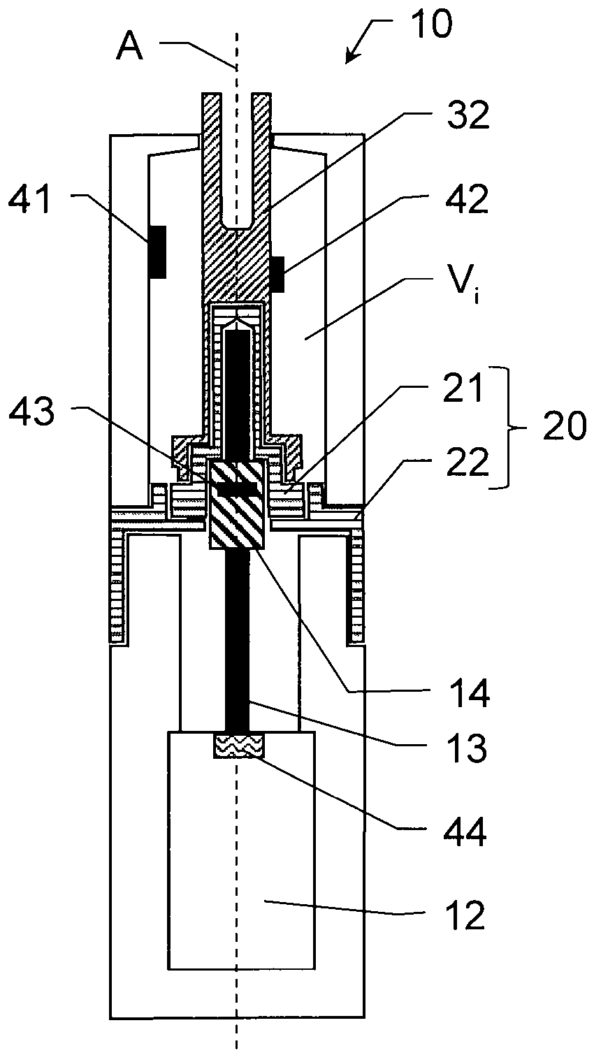
Die
Ein Tragstift
Die Kupplung
Eine optionale thermische und elektrische Isolierung zwischen dem oberen Kupplungsteil und dem unteren Antriebsteil ist in einer Variante durch ein erstes Isolierelement
In einer weiteren Variante können sowohl die Gewindespindel
Der Pin-Lifter
Die Stifthubvorrichtung
Einer der beiden Sensoren
Vorteil eines am Pin
Ein Vorteil eines an der Kupplung
Durch die beschriebene Anordnung des Sensors
Der weitere Kraftsensor
Die Kraftsensoren
Durch einen (fortlaufenden) Vergleich eines anliegenden Kraftniveaus mit einem hinterlegten Referenzwert (z.B. zulässige Kraftmaximum) kann eine Prozessüberwachung und eine Erfassung eines Zustands der Stifthubvorrichtung
Die zulässige Maximalkraft kann ebenso für ein Anheben eines Substrats von einer elektrostatischen Klemmvorrichtung definiert sein, wobei durch dessen Überschreitung eine eventuelle Beschädigung des Substrats angezeigt werden kann.The permissible maximum force can also be defined for lifting a substrate from an electrostatic clamping device, wherein if the substrate is exceeded, any damage to the substrate can be indicated.
Anhand eines Kraftverlaufs kann sowohl eine Verschleisserscheinung für eine oder mehrere Komponenten der Stifthubvorrichtung als auch eine Prozessqualität bestimmt werden. Die Bewertungsansätze für die Verwendung eines Beschleunigungssensors (siehe oben) können auf die Verwendung eines Kraftsensors hierfür entsprechend übertragen werden.On the basis of a force curve, both a wear phenomenon for one or more components of the pin lifting device and a process quality can be determined. The evaluation approaches for the use of an acceleration sensor (see above) can be transferred accordingly to the use of a force sensor for this.
Bei einer gemessenen Abweichung des Kraftverlaufs von einer dafür definierten Referenz kann ein Warnsignal ausgegeben werden. Eine Art der Abweichung kann ausgewertet und hinsichtlich einer möglichen Ursache analysiert werden. Beispielsweise lassen bestimmte Muster einer Abweichung Rückschlüsse auf die Quelle für die Abweichung und/oder die Auswirkung auf das System bzw. die Stifthubvorrichtung
Die Messdaten des Kraftsensors
Der Pin-Lifter
Mit einer solchen Anordnung kann neben oben beschriebenen Funktionen beispielsweise auch eine Überwachung der gewünschten Isolierwirkung z.B. des Isolierelements
Es versteht sich, dass die dargestellten Figuren nur mögliche Ausführungsbeispiele schematisch darstellen. Die verschiedenen Ansätze können erfindungsgemäss ebenso miteinander sowie mit Vorrichtungen zur Substratbewegung in Vakuumprozesskammern, insbesondere Pin-Liftern, des Stands der Technik kombiniert werden.It is understood that the figures shown represent only possible exemplary embodiments schematically. According to the invention, the various approaches can also be combined with one another and with devices for moving the substrate in vacuum process chambers, in particular pin lifters, of the prior art.
ZITATE ENTHALTEN IN DER BESCHREIBUNG QUOTES INCLUDE IN THE DESCRIPTION
Diese Liste der vom Anmelder aufgeführten Dokumente wurde automatisiert erzeugt und ist ausschließlich zur besseren Information des Lesers aufgenommen. Die Liste ist nicht Bestandteil der deutschen Patent- bzw. Gebrauchsmusteranmeldung. Das DPMA übernimmt keinerlei Haftung für etwaige Fehler oder Auslassungen.This list of documents listed by the applicant has been generated automatically and is only included for the better information of the reader. The list is not part of the German patent or utility model application. The DPMA assumes no liability for any errors or omissions.
Zitierte PatentliteraturPatent literature cited
- US 6481723 B1 [0010]US 6481723 B1 [0010]
- US 6646857 B2 [0011]US 6646857 B2 [0011]
Claims (18)
Priority Applications (7)
| Application Number | Priority Date | Filing Date | Title |
|---|---|---|---|
| DE102018009871.1A DE102018009871A1 (en) | 2018-12-19 | 2018-12-19 | Pen lifter with condition monitoring |
| TW108143590A TWI827744B (en) | 2018-12-19 | 2019-11-29 | Pin lifting device with condition monitoring |
| KR1020217021212A KR102768924B1 (en) | 2018-12-19 | 2019-12-13 | Pin lifting device using condition monitoring |
| JP2021535173A JP7548905B2 (en) | 2018-12-19 | 2019-12-13 | Pin lifting device with condition monitoring |
| PCT/EP2019/085063 WO2020126901A1 (en) | 2018-12-19 | 2019-12-13 | Pin-lifting device having state monitoring |
| CN201980083018.3A CN113228247B (en) | 2018-12-19 | 2019-12-13 | Pin lift with condition monitoring |
| US17/415,863 US20220076987A1 (en) | 2018-12-19 | 2019-12-13 | Pin-lifting device having state monitoring |
Applications Claiming Priority (1)
| Application Number | Priority Date | Filing Date | Title |
|---|---|---|---|
| DE102018009871.1A DE102018009871A1 (en) | 2018-12-19 | 2018-12-19 | Pen lifter with condition monitoring |
Publications (1)
| Publication Number | Publication Date |
|---|---|
| DE102018009871A1 true DE102018009871A1 (en) | 2020-06-25 |
Family
ID=69157768
Family Applications (1)
| Application Number | Title | Priority Date | Filing Date |
|---|---|---|---|
| DE102018009871.1A Withdrawn DE102018009871A1 (en) | 2018-12-19 | 2018-12-19 | Pen lifter with condition monitoring |
Country Status (7)
| Country | Link |
|---|---|
| US (1) | US20220076987A1 (en) |
| JP (1) | JP7548905B2 (en) |
| KR (1) | KR102768924B1 (en) |
| CN (1) | CN113228247B (en) |
| DE (1) | DE102018009871A1 (en) |
| TW (1) | TWI827744B (en) |
| WO (1) | WO2020126901A1 (en) |
Cited By (2)
| Publication number | Priority date | Publication date | Assignee | Title |
|---|---|---|---|---|
| CN113488404A (en) * | 2021-05-30 | 2021-10-08 | 周洪 | Silicon wafer laser annealing positioning device and using method thereof |
| WO2022028853A1 (en) | 2020-08-06 | 2022-02-10 | Vat Holding Ag | Pin lifting device |
Families Citing this family (9)
| Publication number | Priority date | Publication date | Assignee | Title |
|---|---|---|---|---|
| DE102018009630A1 (en) * | 2018-12-11 | 2020-06-18 | Vat Holding Ag | Pen lifting device with temperature sensor |
| US12308277B2 (en) * | 2020-09-25 | 2025-05-20 | Changxin Memory Technologies, Inc. | Wafer processing device and wafer conveying method |
| US12211734B2 (en) * | 2021-03-12 | 2025-01-28 | Applied Materials, Inc. | Lift pin mechanism |
| CN113488370B (en) * | 2021-07-06 | 2024-05-31 | 北京屹唐半导体科技股份有限公司 | Lift Pin Assemblies for Plasma Processing Equipment |
| US11972935B2 (en) * | 2021-08-27 | 2024-04-30 | Taiwan Semiconductor Manufacturing Co., Ltd. | Methods for processing a semiconductor substrate |
| JP7715464B2 (en) * | 2021-09-02 | 2025-07-30 | 東京エレクトロン株式会社 | Substrate Processing Equipment |
| CN114551302B (en) * | 2022-02-21 | 2025-08-26 | 北京北方华创微电子装备有限公司 | Semiconductor process equipment, lifting mechanism thereof and control method thereof |
| KR102715846B1 (en) * | 2022-05-11 | 2024-10-11 | 피에스케이홀딩스 (주) | Apparatus for treating substrate and method of treating substrate for remedy of substrate sticky phenomenon |
| KR102884561B1 (en) * | 2023-07-19 | 2025-11-17 | 주식회사 유니큐 | Monitoring System for Slot Valve |
Citations (4)
| Publication number | Priority date | Publication date | Assignee | Title |
|---|---|---|---|---|
| US6481723B1 (en) | 2001-03-30 | 2002-11-19 | Lam Research Corporation | Lift pin impact management |
| US6646857B2 (en) | 2001-03-30 | 2003-11-11 | Lam Research Corporation | Semiconductor wafer lifting device and methods for implementing the same |
| US20130059447A1 (en) * | 2009-03-24 | 2013-03-07 | Lam Research Corporation | Method and apparatus for reduction of voltage potential spike during dechucking |
| EP3361316A1 (en) * | 2017-02-14 | 2018-08-15 | VAT Holding AG | Pneumatic pin lifting device and pneumatic lifting cylinder |
Family Cites Families (22)
| Publication number | Priority date | Publication date | Assignee | Title |
|---|---|---|---|---|
| US4382739A (en) * | 1980-12-24 | 1983-05-10 | International Business Machines Corporation | Light actuating force elevator drive mechanism |
| JPH05129421A (en) * | 1991-11-07 | 1993-05-25 | Fujitsu Ltd | Electrostatic check |
| US6205870B1 (en) * | 1997-10-10 | 2001-03-27 | Applied Komatsu Technology, Inc. | Automated substrate processing systems and methods |
| JP2004281783A (en) * | 2003-03-17 | 2004-10-07 | Renesas Technology Corp | Semiconductor processing equipment |
| US7292428B2 (en) | 2005-04-26 | 2007-11-06 | Applied Materials, Inc. | Electrostatic chuck with smart lift-pin mechanism for a plasma reactor |
| KR20060125072A (en) * | 2005-06-01 | 2006-12-06 | 삼성전자주식회사 | Semiconductor device manufacturing equipment |
| US20080108154A1 (en) * | 2006-11-03 | 2008-05-08 | Hyoung Kyu Son | Apparatus and method for measuring chuck attachment force |
| US7712370B2 (en) * | 2006-12-22 | 2010-05-11 | Asm Japan K.K. | Method of detecting occurrence of sticking of substrate |
| CN101688806B (en) * | 2007-07-24 | 2012-05-16 | A&D有限公司 | Built-in weight lifting device |
| TW201005825A (en) * | 2008-05-30 | 2010-02-01 | Panasonic Corp | Plasma processing apparatus and method |
| US20100013626A1 (en) * | 2008-07-15 | 2010-01-21 | Applied Materials, Inc. | Substrate lift pin sensor |
| JP2010278271A (en) | 2009-05-29 | 2010-12-09 | Panasonic Corp | Semiconductor substrate processing equipment |
| JP5551420B2 (en) * | 2009-12-04 | 2014-07-16 | 東京エレクトロン株式会社 | Substrate processing apparatus, method for measuring distance between electrodes thereof, and storage medium for storing program |
| KR102110000B1 (en) * | 2012-08-31 | 2020-05-12 | 세미컨덕터 테크놀로지스 앤드 인스트루먼츠 피티이 엘티디 | Single ultra-planar wafer table structure for both wafers and film frames |
| US9108322B2 (en) * | 2013-04-29 | 2015-08-18 | Varian Semiconductor Equipment Associates, Inc. | Force sensing system for substrate lifting apparatus |
| JP6244317B2 (en) * | 2015-01-28 | 2017-12-06 | 東京エレクトロン株式会社 | Substrate processing equipment |
| JP2016146416A (en) * | 2015-02-09 | 2016-08-12 | 株式会社Screenホールディングス | Method and system for substrate processing |
| JP6817745B2 (en) | 2015-09-01 | 2021-01-20 | 東京エレクトロン株式会社 | Substrate processing device, lift pin height position detection method, lift pin height position adjustment method, and lift pin abnormality detection method |
| TW201839890A (en) | 2017-02-13 | 2018-11-01 | 日商東京威力科創股份有限公司 | Transfer device, transfer method, and storage medium |
| EP3372881A1 (en) * | 2017-03-07 | 2018-09-12 | VAT Holding AG | Optimized pressure control for and with a vacuum valve |
| EP3372883B1 (en) * | 2017-03-09 | 2019-12-11 | VAT Holding AG | Vacuum valve with optical sensor |
| WO2019027801A1 (en) * | 2017-08-01 | 2019-02-07 | Applied Materials, Inc. | Active monitoring system for substrate breakage prevention |
-
2018
- 2018-12-19 DE DE102018009871.1A patent/DE102018009871A1/en not_active Withdrawn
-
2019
- 2019-11-29 TW TW108143590A patent/TWI827744B/en active
- 2019-12-13 CN CN201980083018.3A patent/CN113228247B/en active Active
- 2019-12-13 US US17/415,863 patent/US20220076987A1/en active Pending
- 2019-12-13 WO PCT/EP2019/085063 patent/WO2020126901A1/en not_active Ceased
- 2019-12-13 KR KR1020217021212A patent/KR102768924B1/en active Active
- 2019-12-13 JP JP2021535173A patent/JP7548905B2/en active Active
Patent Citations (4)
| Publication number | Priority date | Publication date | Assignee | Title |
|---|---|---|---|---|
| US6481723B1 (en) | 2001-03-30 | 2002-11-19 | Lam Research Corporation | Lift pin impact management |
| US6646857B2 (en) | 2001-03-30 | 2003-11-11 | Lam Research Corporation | Semiconductor wafer lifting device and methods for implementing the same |
| US20130059447A1 (en) * | 2009-03-24 | 2013-03-07 | Lam Research Corporation | Method and apparatus for reduction of voltage potential spike during dechucking |
| EP3361316A1 (en) * | 2017-02-14 | 2018-08-15 | VAT Holding AG | Pneumatic pin lifting device and pneumatic lifting cylinder |
Cited By (5)
| Publication number | Priority date | Publication date | Assignee | Title |
|---|---|---|---|---|
| WO2022028853A1 (en) | 2020-08-06 | 2022-02-10 | Vat Holding Ag | Pin lifting device |
| DE102020120732A1 (en) | 2020-08-06 | 2022-02-10 | Vat Holding Ag | pin lifting device |
| TWI891860B (en) * | 2020-08-06 | 2025-08-01 | 瑞士商Vat控股股份有限公司 | Stifthubvorrichtung |
| CN113488404A (en) * | 2021-05-30 | 2021-10-08 | 周洪 | Silicon wafer laser annealing positioning device and using method thereof |
| CN113488404B (en) * | 2021-05-30 | 2023-01-13 | 深圳市嘉伟亿科技有限公司 | Silicon wafer laser annealing positioning device and using method thereof |
Also Published As
| Publication number | Publication date |
|---|---|
| TW202032707A (en) | 2020-09-01 |
| JP7548905B2 (en) | 2024-09-10 |
| KR20210104075A (en) | 2021-08-24 |
| TWI827744B (en) | 2024-01-01 |
| WO2020126901A1 (en) | 2020-06-25 |
| CN113228247B (en) | 2024-06-28 |
| KR102768924B1 (en) | 2025-02-18 |
| CN113228247A (en) | 2021-08-06 |
| JP2022514747A (en) | 2022-02-15 |
| US20220076987A1 (en) | 2022-03-10 |
Similar Documents
| Publication | Publication Date | Title |
|---|---|---|
| DE102018009871A1 (en) | Pen lifter with condition monitoring | |
| WO2021099403A1 (en) | Method for monitoring, determining the position of, and positioning a pin-lifting system | |
| EP1998932B1 (en) | Chuck body for a clamping chuck, clamping chuck and method for determining a clamping force on such a clamping chuck | |
| DE102019219149A1 (en) | TEST DEVICE | |
| WO2020120510A1 (en) | Pin lifting device having a temperature sensor | |
| EP3283864A1 (en) | Linear guiding device for a feed axis of a machine tool | |
| WO2007131709A1 (en) | Test device for tribological examination of materials | |
| WO2019002489A1 (en) | Vacuum valve with inertial sensor | |
| DE102023128853A1 (en) | DEVICE FOR AUTOMATIC INTERNAL DIAMETER MEASUREMENT | |
| DE102018007905A1 (en) | Working spindle with sensors and methods for recording and monitoring their history | |
| EP3593379A1 (en) | Electrostatic substrate retainer | |
| DE102011088321B4 (en) | Pneumatically determining the elevation of a device relative to a device holder | |
| DE102018006903A1 (en) | Galvanically isolated pin lifting device | |
| DE69123279T2 (en) | Transport device for substrates and method for control | |
| EP3421849A1 (en) | Vacuum valve with temperature sensor | |
| DE102021128314A1 (en) | Concentricity monitoring modules and concentricity monitoring methods for a tool that is to be rotated during operation | |
| DE102019006050A1 (en) | Pin lifting device with sliding guide | |
| DE102010019677A1 (en) | Method and apparatus for conditioning bearing systems for shafts | |
| EP2085636B1 (en) | Device and method for determining the switch state of a brake or coupling | |
| DE102019135740A1 (en) | Component holding device with elastic spring element and pneumatic channel system; Placement head and placement machine as well as methods for placing component carriers | |
| DE10058757A1 (en) | Godet roller for processing melt-spun yarns, includes actuator to adjust axial pre-tensioning of bearing supports while running | |
| WO2021074270A1 (en) | Adjustment device for a vacuum area with pressure measuring functionality | |
| EP3608066A1 (en) | Method for monitoring the functionality of gripper jaws and gripper jaws | |
| DE102014106100A1 (en) | Method and apparatus for uniforming a substrate stack | |
| DE102022118970A1 (en) | Method for providing and gripping components by an industrial robot |
Legal Events
| Date | Code | Title | Description |
|---|---|---|---|
| R163 | Identified publications notified | ||
| R119 | Application deemed withdrawn, or ip right lapsed, due to non-payment of renewal fee |