DE102018009849A1 - Wet running pump - Google Patents
Wet running pump Download PDFInfo
- Publication number
- DE102018009849A1 DE102018009849A1 DE102018009849.5A DE102018009849A DE102018009849A1 DE 102018009849 A1 DE102018009849 A1 DE 102018009849A1 DE 102018009849 A DE102018009849 A DE 102018009849A DE 102018009849 A1 DE102018009849 A1 DE 102018009849A1
- Authority
- DE
- Germany
- Prior art keywords
- piston ring
- rotor
- housing
- pump
- wet
- Prior art date
- Legal status (The legal status is an assumption and is not a legal conclusion. Google has not performed a legal analysis and makes no representation as to the accuracy of the status listed.)
- Granted
Links
Images
Classifications
-
- F—MECHANICAL ENGINEERING; LIGHTING; HEATING; WEAPONS; BLASTING
- F04—POSITIVE - DISPLACEMENT MACHINES FOR LIQUIDS; PUMPS FOR LIQUIDS OR ELASTIC FLUIDS
- F04D—NON-POSITIVE-DISPLACEMENT PUMPS
- F04D13/00—Pumping installations or systems
- F04D13/02—Units comprising pumps and their driving means
- F04D13/06—Units comprising pumps and their driving means the pump being electrically driven
- F04D13/0606—Canned motor pumps
- F04D13/0633—Details of the bearings
-
- F—MECHANICAL ENGINEERING; LIGHTING; HEATING; WEAPONS; BLASTING
- F04—POSITIVE - DISPLACEMENT MACHINES FOR LIQUIDS; PUMPS FOR LIQUIDS OR ELASTIC FLUIDS
- F04D—NON-POSITIVE-DISPLACEMENT PUMPS
- F04D29/00—Details, component parts, or accessories
- F04D29/08—Sealings
- F04D29/10—Shaft sealings
- F04D29/12—Shaft sealings using sealing-rings
- F04D29/126—Shaft sealings using sealing-rings especially adapted for liquid pumps
-
- F—MECHANICAL ENGINEERING; LIGHTING; HEATING; WEAPONS; BLASTING
- F04—POSITIVE - DISPLACEMENT MACHINES FOR LIQUIDS; PUMPS FOR LIQUIDS OR ELASTIC FLUIDS
- F04D—NON-POSITIVE-DISPLACEMENT PUMPS
- F04D29/00—Details, component parts, or accessories
- F04D29/40—Casings; Connections of working fluid
- F04D29/42—Casings; Connections of working fluid for radial or helico-centrifugal pumps
- F04D29/426—Casings; Connections of working fluid for radial or helico-centrifugal pumps especially adapted for liquid pumps
Landscapes
- Engineering & Computer Science (AREA)
- Mechanical Engineering (AREA)
- General Engineering & Computer Science (AREA)
- Structures Of Non-Positive Displacement Pumps (AREA)
Abstract
Nassläuferpumpe umfassend ein Pumpengehäuse (1) mit einem Pumpenraum (2), in dem ein Laufrad (3) angeordnet ist, und einen elektrischen Antriebsmotor mit einer drehbaren Motorwelle (4) und einem darauf befestigten Rotor (6), wobei die Motorwelle (4) an einem Axialende das Laufrad (3) trägt und der Rotor (6) in einem vom zu fördernden Medium durchströmbaren Rotorraum (7) einliegt, und wobei der Rotorraum (7) vom Pumpenraum (2) getrennt ist und eine Dichtung (9) den radialen Dichtspalt zur Motorwelle (4) hin abdichtet, wobei die Dichtung (9) durch einen die Motorwelle (4) federnd umgreifenden Kolbenring gebildet ist.
Description
Die Erfindung betrifft eine Nassläuferpumpe umfassend ein Pumpengehäuse mit einem Pumpenraum, in dem ein Laufrad angeordnet ist, und einen elektrischen Antriebsmotor mit einer drehbaren Motorwelle und einem darauf befestigten Rotor, wobei die Motorwelle an einem Axialende das Laufrad trägt und der Rotor in einem vom zu fördernden Medium durchströmbaren Rotorraum einliegt, und wobei der Rotorraum vom Pumpenraum getrennt ist und eine Dichtung den radialen Dichtspalt zur Motorwelle hin abdichtet.The invention relates to a wet-running pump comprising a pump housing with a pump chamber, in which an impeller is arranged, and an electric drive motor with a rotatable motor shaft and a rotor fastened thereon, the motor shaft carrying the impeller at one axial end and the rotor in one to be conveyed Medium flows through the rotor chamber, and wherein the rotor chamber is separated from the pump chamber and a seal seals the radial sealing gap to the motor shaft.
Nassläuferpumpen sind typischerweise so konzipiert, dass der Rotor in dem Rotorraum einliegt, der durch einen Spalttopf gebildet ist. Der Spalttopf befindet sich zwischen dem Rotor und einem Stator der Nassläuferpumpe. Innerhalb des Rotorraums befindet sich Flüssigkeit, die zur Schmierung und Kühlung des Rotors vorgesehen ist. Insbesondere werden durch die Flüssigkeit auch die zur Lagerung der Motorwelle vorgesehenen Lagerelemente geschmiert. Obgleich die Flüssigkeit im Rotorraum der Nassläuferpumpe zur Schmierung und Kühlung erforderlich ist, ist es für den Betrieb der Nassläuferpumpe wichtig, dass die Flüssigkeit nicht ungehindert aus dem Pumpenraum in den Rotorraum gelangt. Insbesondere sollen in der Flüssigkeit befindliche Partikel nicht den Rotorraum gelangen, da diese zu ungewollten Verschmutzungen führen könnten. Beispielsweise kann durch die Verschmutzungen die Funktion der Lagerelemente beeinträchtigt werden. Zur Verhinderung eines unkontrollierten Eindringens von Flüssigkeit vom Pumpenraum in den Rotorraum ist zwischen dem Pumpenraum und dem Rotorraum eine Dichtung vorgesehen. Durch die Dichtung wird insbesondere verhindert, dass Flüssigkeit entlang der drehbar gelagerten Motorwelle in den Rotorraum gelangt. Typischerweise werden in Kartuschen angeordnete Floating-Ringe als Dichtungen verwendet.Wet running pumps are typically designed so that the rotor lies in the rotor space, which is formed by a containment shell. The containment can is located between the rotor and a stator of the wet-running pump. There is liquid within the rotor space, which is provided for lubricating and cooling the rotor. In particular, the bearing elements provided for mounting the motor shaft are also lubricated by the liquid. Although the liquid in the rotor chamber of the wet-running pump is required for lubrication and cooling, it is important for the operation of the wet-running pump that the liquid does not get into the rotor chamber from the pump chamber unhindered. In particular, particles in the liquid should not get into the rotor space since these could lead to undesired contamination. For example, the function of the bearing elements can be impaired by the soiling. A seal is provided between the pump chamber and the rotor chamber to prevent uncontrolled penetration of liquid from the pump chamber into the rotor chamber. The seal in particular prevents liquid from getting into the rotor space along the rotatably mounted motor shaft. Floating rings arranged in cartridges are typically used as seals.
Aufgabe der zugrundeliegenden Erfindung ist es, eine Dichtung zur Verfügung zu stellen, die Fertigungstoleranzen der Motorwelle kompensiert, nahezu spaltfrei an der Motorwelle anliegt, eine einstellbare Durchströmung des Rotorraums ermöglicht, den Partikeleintrag in den Rotorraum reduziert und in axialer Richtung eine kurze Bauform aufweist.The object of the underlying invention is to provide a seal that compensates for the manufacturing tolerances of the motor shaft, is applied to the motor shaft almost without a gap, allows an adjustable flow through the rotor chamber, reduces the particle entry into the rotor chamber and has a short design in the axial direction.
Die Aufgabe der zugrundeliegenden Erfindung wird durch eine Nassläuferpumpe mit den Merkmalen des Anspruchs 1 gelöst, wobei bevorzugte Ausführungsvarianten der Erfindung durch die abhängigen Ansprüche 2 bis 13 gebildet sind.The object of the underlying invention is achieved by a wet-running pump with the features of
Im Genaueren wird die zugrundeliegende Aufgabe dadurch gelöst, dass die Dichtung durch einen die Motorwelle federnd umgreifenden Kolbenring gebildet ist. Der Kolbenring hat im nicht eingebauten Zustand einen inneren Durchmesser, der kleiner als der äußere Durchmesser der Motorwelle ist, sodass sich im eingebauten Zustand an zwei Umfangsenden des Kolbenrings ein Kolbenringspalt bildet und der Kolbenring kraftschlüssig am radialen Umfang der Motorwelle anliegt.In more detail, the underlying object is achieved in that the seal is formed by a piston ring that resiliently encompasses the motor shaft. When not installed, the piston ring has an inner diameter that is smaller than the outer diameter of the motor shaft, so that in the installed state, a piston ring gap forms at two circumferential ends of the piston ring and the piston ring rests non-positively on the radial circumference of the motor shaft.
Dadurch wird vorteilhafterweise erreicht, dass der radiale Dichtspalt zwischen Kolbenring und Motorwelle reduziert ist. Insbesondere werden durch den federnd umgreifenden Kolbenring Fertigungstoleranzen der Motorwelle ausgeglichen. Der zwischen den Umfangsenden des Kolbenrings vorliegende Kolbenringspalt führt vorteilhafterweise dazu, dass Flüssigkeit vom Pumpenraum in den Rotorraum gelangen kann, wobei durch eine geringe Spaltbreite des Kolbenringspalts das Eindringen von Partikel auf einfache Weise verhindert wird.As a result, the radial sealing gap between the piston ring and the motor shaft is advantageously reduced. In particular, manufacturing tolerances of the motor shaft are compensated for by the spring-encompassing piston ring. The piston ring gap present between the circumferential ends of the piston ring advantageously leads to the fact that liquid can get into the rotor chamber from the pump chamber, the penetration of particles being prevented in a simple manner by a small gap width of the piston ring gap.
Eine bevorzugte Ausführungsvariante der Erfindung zeichnet sich dadurch aus, dass der Kolbenring aus Kunststoff gebildet ist. Besonders bevorzugt ist die Verwendung eines tribologisch optimierten Kunststoffs, der im Hinblick auf das Material der Motorwelle ausgewählt ist. Dadurch werden vorteilhafterweise die Gleiteigenschaften des Kolbenrings auf der Motorwelle verbessert, da die Reibung zwischen beiden Komponenten reduziert ist. Insbesondere hat dies den Vorteil, dass der Verschleiß der Komponenten reduziert und die Effizienz der Nassläuferpumpe verbessert ist.A preferred embodiment variant of the invention is characterized in that the piston ring is formed from plastic. The use of a tribologically optimized plastic which is selected with regard to the material of the motor shaft is particularly preferred. This advantageously improves the sliding properties of the piston ring on the motor shaft, since the friction between the two components is reduced. In particular, this has the advantage that the wear on the components is reduced and the efficiency of the wet-running pump is improved.
In einer bevorzugten Ausführungsvariante der Erfindung ist der Kolbenring axial zwischen einem die Motorwelle lagernden Gleitlager und dem Laufrad angeordnet. Dadurch wird verhindert, dass Flüssigkeit ungehindert aus dem Pumpenraum zum Gleitlager gelangt. Insbesondere werden durch den Kolbenringspalt Partikel herausgefiltert, die sich am Gleitlager absetzen könnten. Vorteilhafterweise wird so erreicht, dass die Gleiteigenschaften des Gleitlagers beim Betrieb der Nassläuferpumpe nicht von Verunreinigungen beeinträchtigt werden, sodass die Effizienz, Betriebssicherheit und Betriebsdauer der Nassläuferpumpe erhöht ist.In a preferred embodiment of the invention, the piston ring is arranged axially between a plain bearing that supports the motor shaft and the impeller. This prevents liquid from getting freely from the pump chamber to the plain bearing. In particular, particles are filtered out through the piston ring gap that could settle on the slide bearing. It is advantageously achieved in this way that the sliding properties of the plain bearing are not impaired by impurities when the wet-running pump is in operation, so that the efficiency, operational safety and operating time of the wet-running pump are increased.
Eine bevorzugte Ausführungsvariante der Erfindung zeichnet sich dadurch aus, dass der Kolbenring an seinen Umfangsenden eine Schlossgeometrie aufweist. Die Schlossgeometrie zeichnet sich dadurch aus, dass der Kolbenringspalt des Kolbenrings zumindest abschnittsweise parallel zu den axialen Stirnseiten des Kolbenrings verläuft. Auf diese Weise bleibt die Spaltbreite des Kolbenringspalts in diesem Abschnitt auch dann konstant, wenn der Kolbenring in radialer Richtung gespreizt oder gestaucht wird. Vorteilhafterweise ist die Filterwirkung bezüglich der Partikelgröße unabhängig von der Spreizung des Kolbenrings, sodass insbesondere Fertigungstoleranzen bei der Wellenherstellung kein Einfluss auf die Filterwirkung des Kolbenrings haben. Zudem ist der Durchfluss an Flüssigkeit durch den Kolbenringspalt unabhängig von der Spreizung des Kolbenrings, da die Spaltbreite des Kolbenrings konstant ist. Die Spaltbreite des Kolbenrings wird so ausgewählt, dass ein ausreichender Durchfluss zur Verfügung steht, jedoch Partikel mit einer kritischen Partikelgröße herausgefiltert werden. Vorzugsweise ist die Schlossgeometrie durch eine L-Geometrie, eine T-Geometrie oder eine Haken-Geometrie gebildet.A preferred embodiment variant of the invention is characterized in that the piston ring has a lock geometry at its circumferential ends. The lock geometry is distinguished by the fact that the piston ring gap of the piston ring runs parallel to the axial end faces of the piston ring, at least in sections. In this way, the gap width of the piston ring gap remains constant in this section even if the piston ring is spread or compressed in the radial direction. The filter effect with respect to the particle size is advantageously independent of the spreading of the piston ring, so that in particular manufacturing tolerances during shaft production have no influence have the filter effect of the piston ring. In addition, the flow of liquid through the piston ring gap is independent of the spreading of the piston ring, since the gap width of the piston ring is constant. The gap width of the piston ring is selected so that sufficient flow is available, but particles with a critical particle size are filtered out. The lock geometry is preferably formed by an L geometry, a T geometry or a hook geometry.
In einer bevorzugten Ausführungsvariante der Erfindung liegt der Kolbenring in einem an einem Lagerschild befestigten ringförmigen Gehäuse zwischen einer laufradseitigen axialen Begrenzungswand und einer rotorseitigen Axialbegrenzungswand ein. Dadurch wird der Kolbenring in axialer Richtung zwischen den beiden axialen Begrenzungswänden gehalten. Insbesondere ist der axiale Abstand zwischen der laufradseitigen axialen Begrenzungswand und der rotorseitigen axialen Begrenzungswand größer als die axiale Dicke des Kolbenrings, sodass dieser schwimmend in dem ringförmigen Gehäuse gelagert ist. Vorteilhafterweise werden so Lagerfehler des Kolbenrings ausgeglichen, da sich der Kolbenring an die Form der Motorwelle anpassen kann.In a preferred embodiment variant of the invention, the piston ring lies in an annular housing fastened to a bearing plate between an impeller-side axial boundary wall and a rotor-side axial boundary wall. As a result, the piston ring is held in the axial direction between the two axial boundary walls. In particular, the axial distance between the impeller-side axial boundary wall and the rotor-side axial boundary wall is greater than the axial thickness of the piston ring, so that it is floatingly supported in the annular housing. Bearing errors of the piston ring are advantageously compensated for in this way, since the piston ring can adapt to the shape of the motor shaft.
Bevorzugt ist das Gehäuse zweiteilig ausgeführt, wobei ein erstes Gehäuseteil die laufradseitige Begrenzungswand und ein zweites Gehäuseteil die rotorseitige Begrenzungswand umfasst. Eine derartige Ausgestaltung des Gehäuses bietet insbesondere im Hinblick auf die Montage den Vorteil, dass alle drei Komponenten, also das erste Gehäuseteil, der Kolbenring und das zweite Gehäuseteil durch axiales Aufeinanderschieben montiert werden können. In einer bevorzugten Ausführungsvariante ist das erste Gehäuseteil am Lagerschild befestigt. Dadurch wird durch den Kolbenring und das erste Gehäuseteil eine Abdichtung zwischen dem Rotorraum und dem Pumpenraum erreicht, da das Lagerschild mit dem den Rotorraum bildeten Spalttopf fluiddicht verbunden ist.The housing is preferably designed in two parts, a first housing part comprising the impeller-side boundary wall and a second housing part the rotor-side boundary wall. Such an embodiment of the housing offers the advantage, in particular with regard to assembly, that all three components, that is to say the first housing part, the piston ring and the second housing part, can be assembled by pushing them axially one on the other. In a preferred embodiment variant, the first housing part is attached to the end shield. As a result, the piston ring and the first housing part provide a seal between the rotor space and the pump space, since the end shield is connected in a fluid-tight manner to the containment shell which forms the rotor space.
Bevorzugt sind die beiden Gehäuseteile mit einander verpresst. Durch das Ineinanderpressen lässt sich auf einfache Weise ein ringförmiges Gehäuse bilden, das eine laufradseitige axiale Begrenzungswand und eine rotorseitige axiale Begrenzungswand aufweist.The two housing parts are preferably pressed together. By pressing one into the other, an annular housing can be formed in a simple manner, which has an axial boundary wall on the impeller side and an axial boundary wall on the rotor side.
Eine bevorzugte Ausführung der Erfindung zeichnet sich dadurch aus, dass zwischen dem Kolbenring und dem Gehäuse ein Formschluss besteht. Durch den Formschluss wird eine Verdrehsicherung für den Kolbenring realisiert, sodass sich dieser nicht mit der Motorwelle mit dreht.A preferred embodiment of the invention is characterized in that there is a positive connection between the piston ring and the housing. The positive locking mechanism ensures that the piston ring is secured against rotation so that it does not rotate with the motor shaft.
Bevorzugt ist der Formschluss durch einen Vorsprung des Gehäuses gebildet, der in den Kolbenringspalt zwischen den Umfangsenden des Kolbenrings greift. Vorteilhafterweise sind so keine baulichen Veränderungen am Kolbenring notwendig, um einen Formschluss zwischen dem Gehäuse und dem Kolbenring zu realisieren. Der Durchfluss durch den Spalt wird dennoch sichergestellt, da der Vorsprung des Gehäuses nur einen Abschnitt des Spalts verschließt.The positive connection is preferably formed by a projection of the housing which engages in the piston ring gap between the circumferential ends of the piston ring. Advantageously, no structural changes to the piston ring are necessary in order to achieve a positive connection between the housing and the piston ring. The flow through the gap is nevertheless ensured because the projection of the housing closes only a section of the gap.
In einer alternativen Ausführungsvariante ist der Formschluss durch zumindest einen Vorsprung des Kolbenrings gebildet, der in eine korrespondierende Aufnahme des Gehäuses greift. Diese Ausführungsvariante hat den Vorteil, dass der Kolbenringspalt nicht durch den Vorsprung des Gehäuses blockiert ist, sondern für einen definierten Flüssigkeitsaustausch zwischen Pumpenraum und Rotorraum zur Verfügung steht.In an alternative embodiment variant, the positive connection is formed by at least one projection of the piston ring which engages in a corresponding receptacle of the housing. This embodiment variant has the advantage that the piston ring gap is not blocked by the projection of the housing, but is available for a defined fluid exchange between the pump chamber and the rotor chamber.
Eine besonders bevorzugte Ausführungsvariante der Erfindung ist dadurch gekennzeichnet, dass das Gehäuse ein einen das Gleitlager aufnehmenden Lagerträger bildet. Der Lagerträger wird dadurch gebildet, dass ein radialer Abschnitt des Gehäuses, insbesondere des ersten Gehäuseteils, das Gleitlager radial umgreift und kraft und/oder formschlüssig mit diesem verbunden ist, vorzugsweise verpresst ist. Dadurch, dass das Gehäuse am Lagerschild befestigt ist, wird durch das Gehäuse auch eine Befestigung des Gleitlagers relativ zum Lagerschild erzielt. Diese Ausführungsvariante hat den Vorteil, dass das Gehäuse zwei Funktionen übernimmt. Zum einen trägt es das Gleitlager zum anderen bildet es das Gehäuse für den Kolbenring. Vorteilhafterweise wird so die Anzahl der Bauteile reduziert. Zudem kann auf diese Weise ein axial kürzerer Aufbau erreicht werden.A particularly preferred embodiment variant of the invention is characterized in that the housing forms a bearing bracket which receives the slide bearing. The bearing bracket is formed in that a radial section of the housing, in particular the first housing part, radially encompasses the slide bearing and is connected to it in a force-locking and / or form-fitting manner, preferably being pressed. Because the housing is fastened to the end shield, the housing also fastens the slide bearing relative to the end shield. This variant has the advantage that the housing performs two functions. On the one hand it carries the plain bearing and on the other hand it forms the housing for the piston ring. The number of components is advantageously reduced in this way. In addition, an axially shorter construction can be achieved in this way.
Bevorzugt ist das Gehäuse zumindest teilweise aus Blech gebildet. Blech hat den Vorteil, dass es auf einfache Weise durch Pressformen in die gewünschte Form überführt werden kann und zudem für die Lagerung des Kolbenrings im Hinblick auf die Stabilität und Lebensdauer vorteilhafte Materialeigenschaften aufweist.The housing is preferably formed at least partially from sheet metal. Sheet metal has the advantage that it can be converted into the desired shape in a simple manner by press molding and, in addition, has advantageous material properties for the storage of the piston ring with regard to stability and durability.
Vorteilhafte Ausführungen der Erfindung werden beispielhaft in den folgenden Figuren dargestellt. Die Figuren zeigen dabei:
-
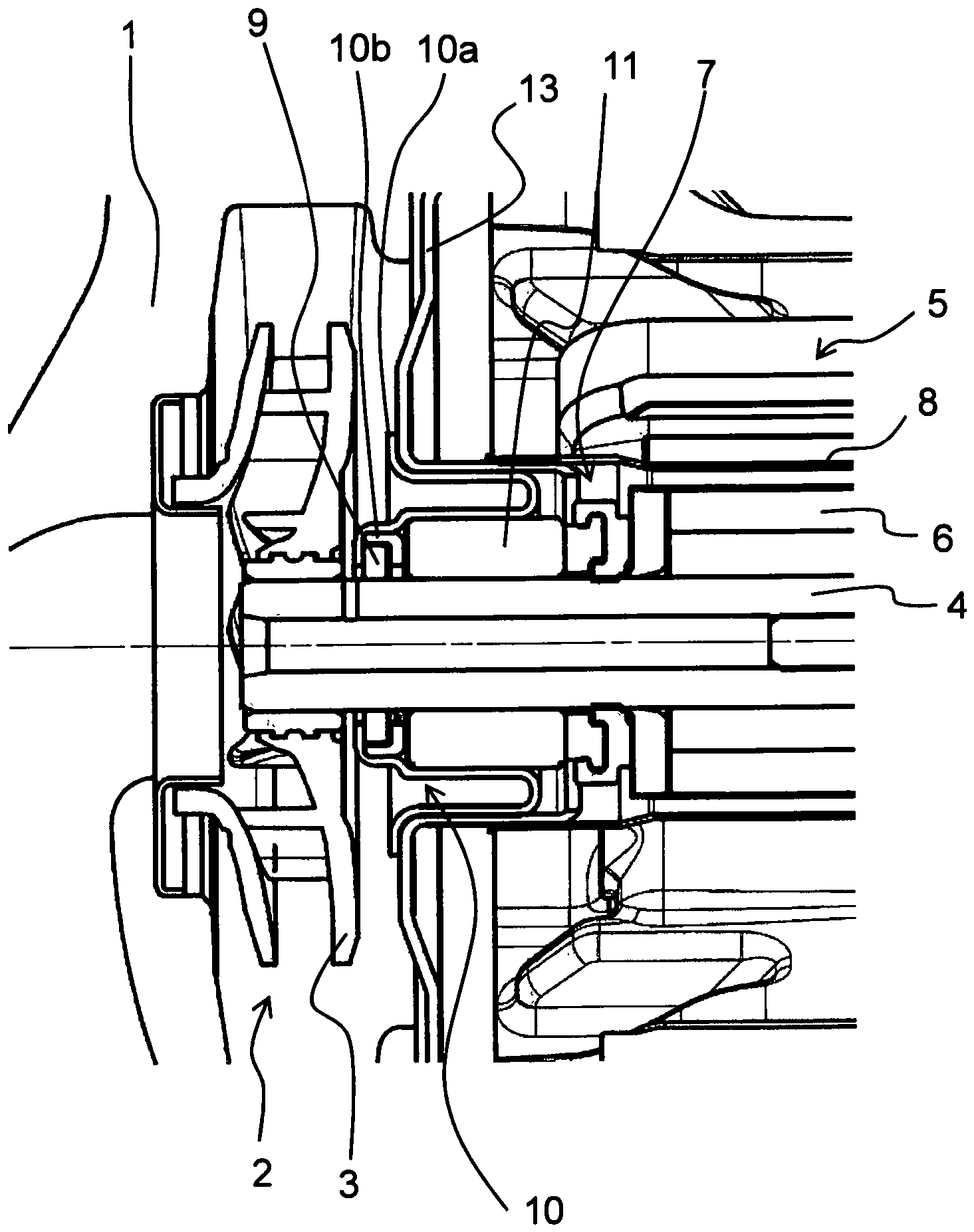
1 einen Längsschnitt durch einen Abschnitt der Nassläuferpumpe, wobei ein Gehäuse eines Kolbenrings als Lagerträger für ein Gleitlager fungiert, -
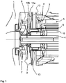
2a einen perspektivischen Längsschnitt durch den Kolbenring, das Gehäuse und das Gleitlager aus1 , -
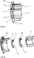
2b eine perspektivische Explosionsdarstellung des Gehäuses, des Kolbenrings und des Gleitlagers aus1 , -
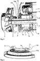
3 einen perspektivischen Längsschnitt durch einen Abschnitt der Nassläuferpumpe, wobei das Gehäuse ausschließlich zur Aufnahme des Kolbenrings vorgesehen ist, und -
4 einen perspektivischen Längsschnitt durch das Gehäuse aus3 mit einliegendem Kolbenring.
-
1 2 shows a longitudinal section through a section of the wet-running pump, a housing of a piston ring acting as a bearing support for a plain bearing, -
2a a perspective longitudinal section through the piston ring, the housing and theplain bearing 1 , -
2 B a perspective exploded view of the housing, the piston ring and theplain bearing 1 , -
3rd a perspective longitudinal section through a section of the wet-running pump, the housing being provided exclusively for receiving the piston ring, and -
4th a perspective longitudinal section through the housing3rd with an inserted piston ring.
Bei der zugrundliegenden Erfindung ist die Dichtung
Der Kolbenring
In
Zur Verdrehsicherung ist der Kolbenring
Zur Realisierung eines definierten Flusses zwischen Pumpenraum
In
In
Zur weiteren definierten Einstellung des Flüssigkeitsaustausches zwischen den Pumpenraum
Das zweite Gehäuseteil
BezugszeichenlisteReference symbol list
- 11
- PumpengehäusePump housing
- 22nd
- PumpenraumPump room
- 33rd
- LaufradWheel
- 44th
- MotorwelleMotor shaft
- 55
- Statorstator
- 66
- Rotorrotor
- 77
- RotorraumRotor space
- 88th
- SpalttopfContainment shell
- 99
- Dichtung, KolbenringSeal, piston ring
- 1010th
- Gehäusecasing
- 10a10a
- erstes Gehäuseteilfirst housing part
- 10b10b
- zweites Gehäuseteilsecond housing part
- 1111
- Gleitlagerbearings
- 1212
- KolbenringspaltPiston ring gap
- 1313
- LagerschildEnd shield
- 1414
- SchlossgeometrieLock geometry
- 1515
-
Vorsprung des Kolbenrings 6Projection of the
piston ring 6 - 1616
-
Aufnahme des Gehäuses 10
Housing 10 - 1717th
-
Vorsprung des Gehäuses 10Protrusion of the
housing 10 - 1818th
- Kanalchannel
- 1919th
- RingdichtungRing seal
Claims (13)
Priority Applications (1)
| Application Number | Priority Date | Filing Date | Title |
|---|---|---|---|
| DE102018009849.5A DE102018009849B4 (en) | 2018-12-18 | 2018-12-18 | Wet rotor pump |
Applications Claiming Priority (1)
| Application Number | Priority Date | Filing Date | Title |
|---|---|---|---|
| DE102018009849.5A DE102018009849B4 (en) | 2018-12-18 | 2018-12-18 | Wet rotor pump |
Publications (2)
| Publication Number | Publication Date |
|---|---|
| DE102018009849A1 true DE102018009849A1 (en) | 2020-06-18 |
| DE102018009849B4 DE102018009849B4 (en) | 2024-08-08 |
Family
ID=70858388
Family Applications (1)
| Application Number | Title | Priority Date | Filing Date |
|---|---|---|---|
| DE102018009849.5A Active DE102018009849B4 (en) | 2018-12-18 | 2018-12-18 | Wet rotor pump |
Country Status (1)
| Country | Link |
|---|---|
| DE (1) | DE102018009849B4 (en) |
Citations (3)
| Publication number | Priority date | Publication date | Assignee | Title |
|---|---|---|---|---|
| DE8811420U1 (en) * | 1988-09-09 | 1989-01-19 | Halm, Richard, 7066 Baltmannsweiler | Wet rotor motor |
| DE102011121149A1 (en) * | 2011-12-15 | 2013-06-20 | Wilo Se | Wet runner pump with prechamber |
| DE102012012443A1 (en) * | 2012-06-22 | 2013-12-24 | Wilo Se | Motor centrifugal pump with a mechanical seal |
-
2018
- 2018-12-18 DE DE102018009849.5A patent/DE102018009849B4/en active Active
Patent Citations (3)
| Publication number | Priority date | Publication date | Assignee | Title |
|---|---|---|---|---|
| DE8811420U1 (en) * | 1988-09-09 | 1989-01-19 | Halm, Richard, 7066 Baltmannsweiler | Wet rotor motor |
| DE102011121149A1 (en) * | 2011-12-15 | 2013-06-20 | Wilo Se | Wet runner pump with prechamber |
| DE102012012443A1 (en) * | 2012-06-22 | 2013-12-24 | Wilo Se | Motor centrifugal pump with a mechanical seal |
Also Published As
| Publication number | Publication date |
|---|---|
| DE102018009849B4 (en) | 2024-08-08 |
Similar Documents
| Publication | Publication Date | Title |
|---|---|---|
| DE4315826B4 (en) | Motor-pump assembly | |
| DE69106471T2 (en) | Counterweight plate for cooling compressors. | |
| DE2661104C2 (en) | ||
| DE3730966C2 (en) | Hermetically sealed rotary piston compressor with a horizontal drive shaft | |
| EP3071840B1 (en) | Load-relieving device | |
| DE10229123A1 (en) | scroll compressor | |
| DE112013003291T5 (en) | Spiral compressor | |
| DE112015006225T5 (en) | Compressor housing for a turbocharger | |
| DE60300051T2 (en) | shaft seal | |
| EP3430271B1 (en) | Centrifugal pump with a sealing device between pressure and suction side | |
| DE102017219004A1 (en) | Electromotive oil pump with check valve | |
| DE102019129494A1 (en) | Coolant pump with improved gap seal | |
| DE112019003289T5 (en) | Scroll compressors | |
| EP2864640B1 (en) | Motorized centrifugal pump with a rotary seal | |
| EP4264053A1 (en) | Scroll compressor for generating oil-free compressed air | |
| AT397994B (en) | SELF-CONVEYING DEVICE FOR LUBRICATING A BEARING ARRANGED ON A SHAFT OR AXLE | |
| DE102018009849A1 (en) | Wet running pump | |
| EP3368801B1 (en) | Shaft sealing arrangement | |
| WO2017076647A1 (en) | Coolant pump for an internal combustion engine | |
| DE10216402A1 (en) | Centrifugal pump with integrated magnetic filter | |
| DE102019200014A1 (en) | Gear pump, especially oil pump | |
| DE102023112736A1 (en) | Devices for compressing a gaseous fluid and method for operating a device for compressing a gaseous fluid | |
| DE102016118627A1 (en) | Pump for liquid fluids with floating rotor bearings | |
| DE2723041A1 (en) | POETRY | |
| DE102021111677B4 (en) | Centrifugal pump with wet-running electric motor |
Legal Events
| Date | Code | Title | Description |
|---|---|---|---|
| R163 | Identified publications notified | ||
| R012 | Request for examination validly filed | ||
| R016 | Response to examination communication | ||
| R018 | Grant decision by examination section/examining division | ||
| R020 | Patent grant now final |