DE102018009839A1 - Valve train for an internal combustion engine, in particular a motor vehicle, and internal combustion engine for a motor vehicle - Google Patents
Valve train for an internal combustion engine, in particular a motor vehicle, and internal combustion engine for a motor vehicle Download PDFInfo
- Publication number
- DE102018009839A1 DE102018009839A1 DE102018009839.8A DE102018009839A DE102018009839A1 DE 102018009839 A1 DE102018009839 A1 DE 102018009839A1 DE 102018009839 A DE102018009839 A DE 102018009839A DE 102018009839 A1 DE102018009839 A1 DE 102018009839A1
- Authority
- DE
- Germany
- Prior art keywords
- camshaft
- axial direction
- actuator
- valve train
- axis
- Prior art date
- Legal status (The legal status is an assumption and is not a legal conclusion. Google has not performed a legal analysis and makes no representation as to the accuracy of the status listed.)
- Withdrawn
Links
- 238000002485 combustion reaction Methods 0.000 title claims description 27
- IHQKEDIOMGYHEB-UHFFFAOYSA-M sodium dimethylarsinate Chemical class [Na+].C[As](C)([O-])=O IHQKEDIOMGYHEB-UHFFFAOYSA-M 0.000 description 4
- BUHVIAUBTBOHAG-FOYDDCNASA-N (2r,3r,4s,5r)-2-[6-[[2-(3,5-dimethoxyphenyl)-2-(2-methylphenyl)ethyl]amino]purin-9-yl]-5-(hydroxymethyl)oxolane-3,4-diol Chemical compound COC1=CC(OC)=CC(C(CNC=2C=3N=CN(C=3N=CN=2)[C@H]2[C@@H]([C@H](O)[C@@H](CO)O2)O)C=2C(=CC=CC=2)C)=C1 BUHVIAUBTBOHAG-FOYDDCNASA-N 0.000 description 1
- 230000005540 biological transmission Effects 0.000 description 1
- 238000011161 development Methods 0.000 description 1
- 230000018109 developmental process Effects 0.000 description 1
Images

Classifications
-
- F—MECHANICAL ENGINEERING; LIGHTING; HEATING; WEAPONS; BLASTING
- F01—MACHINES OR ENGINES IN GENERAL; ENGINE PLANTS IN GENERAL; STEAM ENGINES
- F01L—CYCLICALLY OPERATING VALVES FOR MACHINES OR ENGINES
- F01L13/00—Modifications of valve-gear to facilitate reversing, braking, starting, changing compression ratio, or other specific operations
- F01L13/0015—Modifications of valve-gear to facilitate reversing, braking, starting, changing compression ratio, or other specific operations for optimising engine performances by modifying valve lift according to various working parameters, e.g. rotational speed, load, torque
- F01L13/0036—Modifications of valve-gear to facilitate reversing, braking, starting, changing compression ratio, or other specific operations for optimising engine performances by modifying valve lift according to various working parameters, e.g. rotational speed, load, torque the valves being driven by two or more cams with different shape, size or timing or a single cam profiled in axial and radial direction
-
- F—MECHANICAL ENGINEERING; LIGHTING; HEATING; WEAPONS; BLASTING
- F01—MACHINES OR ENGINES IN GENERAL; ENGINE PLANTS IN GENERAL; STEAM ENGINES
- F01L—CYCLICALLY OPERATING VALVES FOR MACHINES OR ENGINES
- F01L13/00—Modifications of valve-gear to facilitate reversing, braking, starting, changing compression ratio, or other specific operations
- F01L13/0005—Deactivating valves
-
- F—MECHANICAL ENGINEERING; LIGHTING; HEATING; WEAPONS; BLASTING
- F01—MACHINES OR ENGINES IN GENERAL; ENGINE PLANTS IN GENERAL; STEAM ENGINES
- F01L—CYCLICALLY OPERATING VALVES FOR MACHINES OR ENGINES
- F01L13/00—Modifications of valve-gear to facilitate reversing, braking, starting, changing compression ratio, or other specific operations
- F01L13/0015—Modifications of valve-gear to facilitate reversing, braking, starting, changing compression ratio, or other specific operations for optimising engine performances by modifying valve lift according to various working parameters, e.g. rotational speed, load, torque
- F01L13/0036—Modifications of valve-gear to facilitate reversing, braking, starting, changing compression ratio, or other specific operations for optimising engine performances by modifying valve lift according to various working parameters, e.g. rotational speed, load, torque the valves being driven by two or more cams with different shape, size or timing or a single cam profiled in axial and radial direction
- F01L2013/0052—Modifications of valve-gear to facilitate reversing, braking, starting, changing compression ratio, or other specific operations for optimising engine performances by modifying valve lift according to various working parameters, e.g. rotational speed, load, torque the valves being driven by two or more cams with different shape, size or timing or a single cam profiled in axial and radial direction with cams provided on an axially slidable sleeve
-
- F—MECHANICAL ENGINEERING; LIGHTING; HEATING; WEAPONS; BLASTING
- F01—MACHINES OR ENGINES IN GENERAL; ENGINE PLANTS IN GENERAL; STEAM ENGINES
- F01L—CYCLICALLY OPERATING VALVES FOR MACHINES OR ENGINES
- F01L13/00—Modifications of valve-gear to facilitate reversing, braking, starting, changing compression ratio, or other specific operations
- F01L2013/10—Auxiliary actuators for variable valve timing
- F01L2013/103—Electric motors
-
- F—MECHANICAL ENGINEERING; LIGHTING; HEATING; WEAPONS; BLASTING
- F01—MACHINES OR ENGINES IN GENERAL; ENGINE PLANTS IN GENERAL; STEAM ENGINES
- F01L—CYCLICALLY OPERATING VALVES FOR MACHINES OR ENGINES
- F01L2250/00—Camshaft drives characterised by their transmission means
- F01L2250/02—Camshaft drives characterised by their transmission means the camshaft being driven by chains
-
- F—MECHANICAL ENGINEERING; LIGHTING; HEATING; WEAPONS; BLASTING
- F01—MACHINES OR ENGINES IN GENERAL; ENGINE PLANTS IN GENERAL; STEAM ENGINES
- F01L—CYCLICALLY OPERATING VALVES FOR MACHINES OR ENGINES
- F01L2250/00—Camshaft drives characterised by their transmission means
- F01L2250/04—Camshaft drives characterised by their transmission means the camshaft being driven by belts
-
- F—MECHANICAL ENGINEERING; LIGHTING; HEATING; WEAPONS; BLASTING
- F01—MACHINES OR ENGINES IN GENERAL; ENGINE PLANTS IN GENERAL; STEAM ENGINES
- F01L—CYCLICALLY OPERATING VALVES FOR MACHINES OR ENGINES
- F01L2250/00—Camshaft drives characterised by their transmission means
- F01L2250/06—Camshaft drives characterised by their transmission means the camshaft being driven by gear wheels
Landscapes
- Engineering & Computer Science (AREA)
- Mechanical Engineering (AREA)
- General Engineering & Computer Science (AREA)
- Valve Device For Special Equipments (AREA)
Abstract
Die Erfindung betrifft einen Ventiltrieb (10), mit einer Nockenwelle (12), mit einem Nockenelement (16), welches zumindest zwei Nocken (20a, b) zum Betätigen eines Gaswechselventils aufweist und in axialer Richtung (18) der Nockenwelle (12) relativ zu dieser verschiebbar ist, mit einem Aktor (28), mit einem mittels des Aktors (28) in axialer Richtung (18) der Nockenwelle (12) relativ zu dieser verschiebbaren ersten Betätigungselement (30), welches eine Ausnehmung (40) aufweist, und mit einem an dem Nockenelement (16) vorgesehen und mit dem Nockenelement (16) mitverschiebbaren zweiten Betätigungselement (32), welches in die Ausnehmung (40) eingreift, wodurch das Nockenelement (16) über die Betätigungselemente (30, 32) mittels des Aktors (28) in axial relativ zu der Nockenwelle (12) verschiebbar ist, wobei das erste Betätigungselement (30) einander in axialer Richtung (18) gegenüberliegende, die Ausnehmung (40) axial begrenzende und ballig ausgebildete Wandungsbereiche (46, 48) aufweist, an welchen das zweite Betätigungselement (32) zumindest beim Verschieben des Nockenelements (16) abstützbar ist.The invention relates to a valve train (10) with a camshaft (12), with a cam element (16) which has at least two cams (20a, b) for actuating a gas exchange valve and relative in the axial direction (18) of the camshaft (12) is displaceable to the latter, with an actuator (28), with a first actuating element (30), which has a recess (40) and can be displaced relative to the latter by means of the actuator (28) in the axial direction (18) of the camshaft (12), and with a second actuating element (32) provided on the cam element (16) and with the cam element (16), which engages in the recess (40), whereby the cam element (16) via the actuating elements (30, 32) by means of the actuator ( 28) can be displaced axially relative to the camshaft (12), the first actuating element (30) having wall regions (46, 48) which are opposite one another in the axial direction (18) and axially delimiting the recess (40), on which the second actuating element (32) can be supported at least when the cam element (16) is displaced.
Description
Die Erfindung betrifft einen Ventiltrieb für eine Verbrennungskraftmaschine, insbesondere eines Kraftfahrzeugs, gemäß dem Oberbegriff von Patentanspruch 1. Ferner betrifft die Erfindung eine Verbrennungskraftmaschine für ein Kraftfahrzeug, insbesondere für einen Kraftwagen.The invention relates to a valve train for an internal combustion engine, in particular a motor vehicle, according to the preamble of claim 1. Furthermore, the invention relates to an internal combustion engine for a motor vehicle, in particular for a motor vehicle.
Ein solcher Ventiltrieb für eine Verbrennungskraftmaschine, insbesondere eines Kraftfahrzeugs, ist beispielsweise bereits der
Aufgabe der vorliegenden Erfindung ist es, einen Ventiltrieb und eine Verbrennungskraftmaschine der eingangs genannten Art derart weiterzuentwickeln, dass ein besonders verschleißarmer Betrieb realisierbar ist.The object of the present invention is to further develop a valve train and an internal combustion engine of the type mentioned at the outset in such a way that particularly low-wear operation can be achieved.
Diese Aufgabe wird durch einen Ventiltrieb mit den Merkmalen des Patentanspruchs 1 sowie durch eine Verbrennungskraftmaschine mit den Merkmalen des Patentanspruchs 10 gelöst. Vorteilhafte Ausgestaltungen mit zweckmäßigen Weiterbildungen der Erfindung sind in den übrigen Ansprüchen angegeben.This object is achieved by a valve train with the features of claim 1 and by an internal combustion engine with the features of
Um einen Ventiltrieb der im Oberbegriff des Patentanspruchs 1 angegebenen Art derart weiterzuentwickeln, dass ein besonders verschleißarmer Betrieb, insbesondere des Ventiltriebs und somit der Verbrennungskraftmaschine insgesamt, realisiert werden kann, ist es erfindungsgemäß vorgesehen, dass das eine der beiden Betätigungselemente mindestens einen ballig ausgebildeten Wandungsbereich aufweist, an welchem das andere der beiden Betätigungselemente zumindest beim Verschieben des Nockenelements abstützbar und die Balligkeit in einem achsparallelen Schnitt bezogen auf die axiale Richtung der Nockenwelle richtungsasymmetrisch ausgeführt ist. Somit ist die Ausnehmung in eine mit der axialen Richtung der Nockenwelle zusammenfallende erste Richtung durch einen ersten der Wandungsbereiche und in eine mit der axialen Richtung zusammenfallende und der ersten Richtung entgegengesetzte zweite Richtung durch den zweiten Wandungsbereich jeweils zumindest teilweise, insbesondere zumindest überwiegend oder vollständig, begrenzt. Die einander gegenüberliegenden Wandungsbereiche sind dabei, insbesondere auf ihren in axialer Richtung einander zugewandten beziehungsweise gegenüberliegenden Seiten, richtungsasymmetrisch ballig, das heißt beispielsweise konvex, ausgebildet. Dabei ist das zweite Betätigungselement zumindest beim Verschieben des Nockenelements, insbesondere direkt, an den balligen Wandungsbereichen abstützbar. Um beispielsweise das Nockenelement in die erste Richtung zu verschieben, so wird das erste Betätigungselement in die erste Richtung verschoben, insbesondere derart, dass das zweite Betätigungselement in direkte Stützanlage und somit in direkten Kontakt mit dem zweiten balligen Wandungsbereich kommt. Um beispielsweise das Nockenelement in die zweite Richtung zu verschieben, wird das erste Betätigungselement in die zweite Richtung verschoben. Dann kommt das zweite Betätigungselement in direkte Stützanlage und somit in direkten Kontakt mit dem ersten balligen Wandungsbereich.In order to further develop a valve train of the type specified in the preamble of claim 1 in such a way that particularly low-wear operation, in particular of the valve train and thus of the internal combustion engine as a whole, can be achieved, it is provided according to the invention that one of the two actuating elements has at least one convex wall area , on which the other of the two actuating elements can be supported, at least when the cam element is displaced, and the crowning in an axially parallel section with respect to the axial direction of the camshaft. Thus, the recess in a first direction coinciding with the axial direction of the camshaft is delimited at least partially, in particular at least predominantly or completely, by a first of the wall regions and in a second direction coinciding with the axial direction and opposite the first direction by the second wall region . The opposite wall areas are, in particular on their axially facing or opposite sides, directionally asymmetrical, that is, for example, convex. The second actuating element can be supported on the spherical wall regions at least when the cam element is displaced, in particular directly. For example, in order to move the cam element in the first direction, the first actuating element is displaced in the first direction, in particular in such a way that the second actuating element comes into direct support contact and thus comes into direct contact with the second spherical wall area. For example, in order to move the cam element in the second direction, the first actuating element is moved in the second direction. Then the second actuating element comes into direct support and thus comes into direct contact with the first spherical wall area.
Dadurch, dass der jeweilige Wandungsbereich richtungsasymmetrisch ballig ausgebildet ist, ist der jeweilige Wandungsbereich beispielsweise konvex, wobei der jeweilige Wandungsbereich vorzugsweise eine von einem Kreis beziehungsweise von einem Kreissegment unterschiedliche Form aufweist. Durch die richtungsasymmetrisch ballige Ausgestaltung der Wandungsbereiche können übermäßige Kontaktkräfte zwischen den Betätigungselementen und somit eine übermäßige Belastung der Betätigungselemente vermieden werden, sodass ein besonders verschleißarmer Betrieb gewährleistet werden kann.Because the respective wall area is convex in a directionally asymmetrical manner, the respective wall area is, for example, convex, the respective wall area preferably having a shape different from a circle or from a segment of a circle. Due to the directionally asymmetrical crowned design of the wall areas, excessive contact forces between the actuating elements and thus an excessive load on the actuating elements can be avoided, so that particularly low-wear operation can be guaranteed.
In einer bevorzugten Ausführungsform weist das eine der beiden Betätigungselemente einen zweiten ballig ausgebildeten Wandungsbereich auf und/oder weist das andere der beiden Betätigungselemente mindestens einen ballig ausgebildeten Wandungsbereich auf, an welchem jeweils das andere der beiden Betätigungselemente zumindest beim Verschieben des Nockenelements abstützbar und die Balligkeit ist in einem achsparallelen Schnitt bezogen auf die axiale Richtung der Nockenwelle richtungsasymmetrisch ausgeführt.In a preferred embodiment, the one of the two actuating elements has a second spherical wall area and / or the other of the two actuating elements has at least one spherical wall region, on each of which the other of the two actuating elements at least when Moving the cam element can be supported and the crowning is carried out in a direction parallel to the axis in an axially parallel section with respect to the axial direction of the camshaft.
Dabei hat es sich als besonders vorteilhaft gezeigt, wenn die balligen Wandungsbereiche bezogen auf die axiale Richtung der Nockenwelle asymmetrisch zueinander angeordnet sind. Das erste Betätigungselement ist beispielsweise entlang einer Bewegungsrichtung relativ zu der Nockenwelle verschiebbar, wobei die Bewegungsrichtung mit der axialen Richtung der Nockenwelle zusammenfällt beziehungsweise parallel zur axialen Richtung verläuft. Somit verlaufen beispielsweise die Bewegungsrichtung und axiale Richtung senkrecht zu einer gemeinsamen Ebene. Dabei sind die jeweiligen Wandungsbereiche bezogen auf die Bewegungsrichtung asymmetrisch zueinander angeordnet beziehungsweise asymmetrisch zueinander ballig ausgebildet. Dieser Ausführungsform liegt die Erkenntnis zugrunde, dass es toleranz- und/oder montagebedingt und somit unvermeidbar zu Schiefstellungen des beispielsweise als Scheibe ausgebildeten zweiten Betätigungselements kommen kann, insbesondere bezogen auf die Bewegungsrichtung beziehungsweise bezogen auf die axiale Richtung. Solche Schiefstellungen können bei regelmäßig auftretenden Betriebsbedingungen und insbesondere bei symmetrischer Balligkeit der Wandungsbereiche zu einem unerwünschten Verschleiß führen, was nun dadurch vermieden werden kann, wenn die balligen Wandungsbereiche bezogen auf die axiale Richtung beziehungsweise bezogen auf die Bewegungsrichtung asymmetrisch zueinander angeordnet beziehungsweise ausgebildet sind.It has proven to be particularly advantageous if the spherical wall areas are arranged asymmetrically with respect to one another with respect to the axial direction of the camshaft. The first actuating element can be displaced, for example, along a direction of movement relative to the camshaft, the direction of movement coinciding with the axial direction of the camshaft or running parallel to the axial direction. Thus, for example, the direction of movement and the axial direction run perpendicular to a common plane. The respective wall areas are arranged asymmetrically with respect to one another with respect to the direction of movement or are configured asymmetrically with respect to one another. This embodiment is based on the knowledge that, due to tolerances and / or assembly and thus inevitably, misalignments of the second actuating element, for example in the form of a disc, can occur, in particular in relation to the direction of movement or in relation to the axial direction. Such misalignments can lead to undesired wear in the case of regularly occurring operating conditions and in particular in the case of symmetrical crowning of the wall regions, which can now be avoided if the spherical wall regions are arranged or designed asymmetrically with respect to one another in relation to the axial direction or in relation to the direction of movement.
Unter dem Merkmal, dass der jeweilige Wandungsbereich ballig ausgebildet ist, ist insbesondere folgendes zu verstehen: Der jeweilige Wandungsbereich bildet eine Kontaktfläche, mit welcher das zweite Betätigungselement beim Verschieben des Nockenelements und somit beim Verschieben des zweiten Betätigungselements in direkte Stützanlage, das heißt in direkten Kontakt, kommen kann beziehungsweise kommt. Dabei ist die jeweilige Kontaktfläche ballig ausgebildet.The feature that the respective wall area is spherical is to be understood in particular as follows: the respective wall area forms a contact surface with which the second actuating element when the cam element is displaced and thus when the second actuating element is displaced into direct support system, that is to say in direct contact , can come or comes. The respective contact surface is spherical.
Um übermäßige Belastungen der Betätigungselemente vermeiden und somit einen besonders verschleißarmen Betrieb des Ventiltriebs gewährleisten zu können, ist es in weiterer Ausgestaltung der Erfindung vorgesehen, dass der Ventiltrieb wenigstens oder genau eine Symmetrieachse aufweist, entlang welcher die balligen Wandungsbereiche beziehungsweise die balligen Kontaktflächen symmetrisch zueinander angeordnet sind.In order to avoid excessive loads on the actuating elements and thus to ensure particularly low-wear operation of the valve train, it is provided in a further embodiment of the invention that the valve train has at least or exactly one axis of symmetry, along which the spherical wall areas or the spherical contact surfaces are arranged symmetrically to one another .
Dabei hat es sich als besonders vorteilhaft gezeigt, wenn die Symmetrieachse schräg zur axialen Richtung der Nockenwelle verläuft. Hierunter ist insbesondere zu verstehen, dass die Symmetrieachse senkrecht zu einer zweiten Ebene verläuft, welche sich schräg zu der zuvor genannten ersten Ebene erstreckt. Hierdurch können beispielsweise etwaige Schiefstellungen des beispielsweise als Scheibe ausgebildeten zweiten Betätigungselements kompensiert werden beziehungsweise es können übermäßige, aus solchen Schiefstellungen resultierende Belastungen vermieden werden.It has proven to be particularly advantageous if the axis of symmetry extends obliquely to the axial direction of the camshaft. This is to be understood in particular to mean that the axis of symmetry runs perpendicular to a second plane which extends obliquely to the aforementioned first plane. In this way, for example, any misalignments of the second actuating element, for example in the form of a disc, can be compensated for or excessive loads resulting from such misalignments can be avoided.
Als weiterhin besonders vorteilhaft hat es sich gezeigt, wenn ein auf der Symmetrieachse liegender Punkt, welcher bezogen auf die axiale Richtung beziehungsweise bezogen auf die Bewegungsrichtung mittig zwischen den Wandungsbereichen, das heißt in der Mitte zwischen den Wandungsbereichen, liegt, entlang einer senkrecht zur axialen Richtung beziehungsweise senkrecht zur Bewegungsrichtung verlaufenden Erstreckung der Ausnehmung näher an einem ersten Ende als an einem dem ersten Ende gegenüberliegenden zweiten Ende der Ausnehmung angeordnet ist, wobei sich die Ausnehmung entlang der genannten Richtung von einem der Enden zu dem anderen Ende beziehungsweise umgekehrt und nicht über das jeweilige Ende hinaus erstreckt, sodass die Ausnehmung entlang der genannten Richtung an dem jeweiligen Ende endet beziehungsweise beginnt.It has also been shown to be particularly advantageous if a point lying on the axis of symmetry, which, in relation to the axial direction or in relation to the direction of movement, lies centrally between the wall regions, that is to say in the middle between the wall regions, along a perpendicular to the axial direction or extending perpendicular to the direction of movement of the recess closer to a first end than at a second end of the recess opposite the first end, the recess extending along said direction from one of the ends to the other end or vice versa and not over the respective one End extends beyond, so that the recess ends or begins at the respective end along the direction mentioned.
Bei einer bezogen auf die Bewegungsrichtung beziehungsweise bezogen auf die axiale Richtung symmetrischen Anordnung oder Ausgestaltung der balligen Wandungsbereiche ist es beispielsweise vorgesehen, dass eine dann vorgesehene, weitere Symmetrieachse parallel zur axialen Richtung beziehungsweise senkrecht zur ersten Ebene verläuft. Im Vergleich zu einer solchen, bezogen auf die Bewegungsrichtung symmetrischen Anordnung beziehungsweise Ausgestaltung der balligen Wandungsbereiche ist vorzugsweise vorgesehen, dass die dann vorgesehene, erste Symmetrieachse schräg zur weiteren Symmetrieachse verläuft und/oder, insbesondere entlang der genannten Richtung, versetzt zu der weiteren Symmetrieachse ist, sodass übermäßige Belastungen besonders gut vermieden werden können.In the case of an arrangement or configuration of the spherical wall regions that is symmetrical with respect to the direction of movement or with respect to the axial direction, it is provided, for example, that a further axis of symmetry then provided runs parallel to the axial direction or perpendicular to the first plane. In comparison to such an arrangement or configuration of the spherical wall areas which is symmetrical with respect to the direction of movement, it is preferably provided that the first axis of symmetry then provided runs obliquely to the further axis of symmetry and / or, in particular along the direction mentioned, is offset from the further axis of symmetry. so that excessive loads can be avoided particularly well.
Um übermäßige Belastungen besonders sicher vermeiden zu können, ist es in weiterer Ausgestaltung der Erfindung vorgesehen, dass die balligen Wandungsbereiche die Ausnehmung in axialer Richtung zumindest überwiegend, insbesondere vollständig, begrenzen. Somit ist es vorzugsweise vorgesehen, dass der erste Wandungsbereich die Ausnehmung in die erste Richtung vollständig begrenzt, und vorzugsweise ist es vorgesehen, dass der zweite Wandungsbereich die Ausnehmung in die zweite Richtung vollständig begrenzt.In order to be able to avoid excessive loads particularly safely, it is provided in a further embodiment of the invention that the spherical wall areas at least predominantly, in particular completely, delimit the recess in the axial direction. It is therefore preferably provided that the first wall region completely delimits the recess in the first direction, and it is preferably provided that the second wall region completely delimits the recess in the second direction.
Um einen besonders verschleißarmen und robusten Betrieb gewährleisten zu können, ist es bei einer weiteren Ausführungsform der Erfindung vorgesehen, dass der Aktor einen Motor und einen mittels des Motors um eine Aktordrehachse drehbare Spindel aufweist, auf welcher das erste Betätigungselement angeordnet ist, sodass das erste Betätigungselement mittels der Spindel durch Drehen der Spindel verschiebbar ist. In order to ensure particularly low-wear and robust operation, it is provided in a further embodiment of the invention that the actuator has a motor and a spindle which can be rotated by means of the motor about an axis of rotation of the actuator and on which the first actuating element is arranged, so that the first actuating element is displaceable by rotating the spindle by means of the spindle.
Eine weitere Ausführungsform zeichnet sich dadurch aus, dass der Motor als ein Elektromotor ausgebildet ist, wodurch ein besonders verschleißarmer Betrieb realisiert werden kann.A further embodiment is characterized in that the motor is designed as an electric motor, as a result of which particularly low-wear operation can be implemented.
Schließlich hat es sich als besonders vorteilhaft gezeigt, wenn die Motordrehachse parallel zur axialen Richtung der Nockenwelle verläuft, wodurch übermäßige Belastungen sicher vermieden werden können.Finally, it has proven to be particularly advantageous if the engine rotation axis runs parallel to the axial direction of the camshaft, as a result of which excessive loads can be reliably avoided.
Zur Erfindung gehört auch eine vorzugsweise als Hubkolbenmaschine ausgebildete Verbrennungskraftmaschine für ein Kraftfahrzeugs, insbesondere für einen Kraftwagen wie beispielsweise einen Personenkraftwagen. Die erfindungsgemäße Verbrennungskraftmaschine weist wenigstens einen erfindungsgemäßen Ventiltrieb auf. Vorteile und vorteilhafte Ausgestaltungen der erfindungsgemäßen Verbrennungskraftmaschine sind als Vorteile und vorteilhafte Ausgestaltungen des erfindungsgemäßen Ventiltriebs anzusehen und umgekehrt.The invention also includes an internal combustion engine, preferably designed as a reciprocating piston engine, for a motor vehicle, in particular for a motor vehicle, such as a passenger car. The internal combustion engine according to the invention has at least one valve train according to the invention. Advantages and advantageous configurations of the internal combustion engine according to the invention are to be regarded as advantages and advantageous configurations of the valve train according to the invention and vice versa.
Weitere Vorteile, Merkmale und Einzelheiten der Erfindung ergeben sich aus der nachfolgenden Beschreibung bevorzugter Ausführungsbeispiele sowie anhand der Zeichnung. Die vorstehend in der Beschreibung genannten Merkmale und Merkmalskombinationen sowie die nachfolgend in der Figurenbeschreibung genannten und/oder in den Figuren alleine gezeigten Merkmale und Merkmalskombinationen sind nicht nur in der jeweils angegebenen Kombination, sondern auch in anderen Kombinationen oder in Alleinstellung verwendbar, ohne den Rahmen der Erfindung zu verlassen.Further advantages, features and details of the invention result from the following description of preferred exemplary embodiments and from the drawing. The features and combinations of features mentioned above in the description and the features and combinations of features mentioned below in the description of the figures and / or shown alone in the figures can be used not only in the combination indicated in each case, but also in other combinations or on their own, without the scope of Leaving invention.
Die Zeichnung zeigt in:
-
1 eine schematische Seitenansicht eines erfindungsgemäßen Ventiltriebs für eine Verbrennungskraftmaschine, insbesondere eines Kraftfahrzeugs; -
2 eine schematische Schnittansicht des Ventiltriebs gemäß einer ersten Ausführungsform entlang einer in1 gezeigten SchnittlinieA-A ; -
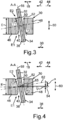
3 eine schematische Schnittansicht des Ventiltriebs gemäß einer zweiten Ausführungsform entlang der in1 gezeigten SchnittlinieA-A ; und -
4 eine weitere schematische Schnittansicht des Ventiltriebs gemäß3 .
-
1 is a schematic side view of a valve train according to the invention for an internal combustion engine, in particular a motor vehicle; -
2nd is a schematic sectional view of the valve train according to a first embodiment along a in1 shown cutting lineAA ; -
3rd is a schematic sectional view of the valve train according to a second embodiment along the in1 shown cutting lineAA ; and -
4th a further schematic sectional view of the valve train according to3rd .
In den Fig. sind gleiche oder funktionsgleiche Elemente mit gleichen Bezugszeichen versehen.In the figures, identical or functionally identical elements are provided with the same reference symbols.
Der Ventiltrieb
Der Ventiltrieb
Bei dem in
Bei dem in
Der Ventiltrieb
Das Betätigungselement
Das Betätigungselement
Mittels des Aktors
Die Ausnehmung
Durch Verschieben des Nockenelements
Um nun einen besonders verschleißarmen Betrieb des Ventiltriebs
Außerdem ist besonders gut aus
Ferner ist aus
Dabei kann insbesondere vorgesehen sein, dass die Wandungsbereiche
Aus den Fig. ist besonders gut erkennbar, dass das Betätigungselement
Die in
In
Mit anderen Worten ist es bei der zweiten Ausführungsform vorgesehen, dass die Balligkeit der Kontaktflächen
Der zweiten Ausführungsform liegen insbesondere die Erkenntnisse zugrunde, dass die bei der ersten Ausführungsform vorgesehenen, symmetrischen Balligkeiten der Kontaktflächen
Des Weiteren ist es vorgesehen, dass der Aktor
Die Spindeldrehachse wird dabei auch als Aktordrehachse oder Motordrehachse bezeichnet. Der Elektromotor
BezugszeichenlisteReference symbol list
- 1010th
- VentiltriebValve train
- 1212
- Nockenwellecamshaft
- 1414
- NockenwellendrehachseCamshaft rotation axis
- 1616
- NockenelementCam element
- 1818th
- DoppelpfeilDouble arrow
- 20a-c20a-c
- Nockencam
- 2222
- NockenteilCam part
- 24a-c24a-c
- Nockencam
- 2626
- NockenteilCam part
- 2828
- AktorActuator
- 30 30th
- erstes Betätigungselementfirst actuator
- 3232
- zweites Betätigungselementsecond actuator
- 3434
- BreitseiteBroadside
- 3636
- BreitseiteBroadside
- 3838
- DoppelpfeilDouble arrow
- 4040
- AusnehmungRecess
- 4242
- Pfeilarrow
- 4444
- Pfeilarrow
- 4646
- WandungsbereichWall area
- 4848
- WandungsbereichWall area
- 5050
- KontaktflächeContact area
- 5252
- KontaktflächeContact area
- 5454
- SymmetrieachseAxis of symmetry
- 5656
- Ebenelevel
- 5858
- PunktPoint
- 6060
- DoppelpfeilDouble arrow
- 6262
- SymmetrieachseAxis of symmetry
- 6464
- ElektromotorElectric motor
- 6565
- PunktPoint
- 6666
- Spindelspindle
- 6868
- AußengewindeExternal thread
- EE
- ErstreckungExtension
- E1E1
- EndeThe End
- E2E2
- EndeThe End
- T1T1
- TraganteilLoad share
- T2T2
- TraganteilLoad share
- VV
- VersatzOffset
- αα
- Winkelangle
ZITATE ENTHALTEN IN DER BESCHREIBUNG QUOTES INCLUDE IN THE DESCRIPTION
Diese Liste der vom Anmelder aufgeführten Dokumente wurde automatisiert erzeugt und ist ausschließlich zur besseren Information des Lesers aufgenommen. Die Liste ist nicht Bestandteil der deutschen Patent- bzw. Gebrauchsmusteranmeldung. Das DPMA übernimmt keinerlei Haftung für etwaige Fehler oder Auslassungen.This list of documents listed by the applicant has been generated automatically and is only included for the better information of the reader. The list is not part of the German patent or utility model application. The DPMA assumes no liability for any errors or omissions.
Zitierte PatentliteraturPatent literature cited
- DE 102015012044 A1 [0002]DE 102015012044 A1 [0002]
- DE 102007037745 A1 [0002]DE 102007037745 A1 [0002]
Claims (10)
Priority Applications (1)
| Application Number | Priority Date | Filing Date | Title |
|---|---|---|---|
| DE102018009839.8A DE102018009839A1 (en) | 2018-12-14 | 2018-12-14 | Valve train for an internal combustion engine, in particular a motor vehicle, and internal combustion engine for a motor vehicle |
Applications Claiming Priority (1)
| Application Number | Priority Date | Filing Date | Title |
|---|---|---|---|
| DE102018009839.8A DE102018009839A1 (en) | 2018-12-14 | 2018-12-14 | Valve train for an internal combustion engine, in particular a motor vehicle, and internal combustion engine for a motor vehicle |
Publications (1)
| Publication Number | Publication Date |
|---|---|
| DE102018009839A1 true DE102018009839A1 (en) | 2020-06-18 |
Family
ID=70858381
Family Applications (1)
| Application Number | Title | Priority Date | Filing Date |
|---|---|---|---|
| DE102018009839.8A Withdrawn DE102018009839A1 (en) | 2018-12-14 | 2018-12-14 | Valve train for an internal combustion engine, in particular a motor vehicle, and internal combustion engine for a motor vehicle |
Country Status (1)
| Country | Link |
|---|---|
| DE (1) | DE102018009839A1 (en) |
Citations (5)
| Publication number | Priority date | Publication date | Assignee | Title |
|---|---|---|---|---|
| DE102004055852A1 (en) * | 2004-09-30 | 2006-04-13 | Bayerische Motoren Werke Ag | Valve drive for internal combustion engine has switch curve device arranged to apply switching force only when cam device is in basic circle phase |
| DE102007037745A1 (en) | 2007-08-10 | 2009-02-12 | Daimler Ag | combustion engine valve |
| DE102008060167A1 (en) * | 2008-11-27 | 2010-06-02 | Dr.Ing.H.C.F.Porsche Aktiengesellschaft | Valve gear of an internal combustion engine |
| DE102015012044A1 (en) | 2015-09-15 | 2017-03-16 | Daimler Ag | Valve train device, in particular for an internal combustion engine |
| DE102017003790A1 (en) * | 2017-04-20 | 2018-10-25 | Daimler Ag | Valve drive device |
-
2018
- 2018-12-14 DE DE102018009839.8A patent/DE102018009839A1/en not_active Withdrawn
Patent Citations (5)
| Publication number | Priority date | Publication date | Assignee | Title |
|---|---|---|---|---|
| DE102004055852A1 (en) * | 2004-09-30 | 2006-04-13 | Bayerische Motoren Werke Ag | Valve drive for internal combustion engine has switch curve device arranged to apply switching force only when cam device is in basic circle phase |
| DE102007037745A1 (en) | 2007-08-10 | 2009-02-12 | Daimler Ag | combustion engine valve |
| DE102008060167A1 (en) * | 2008-11-27 | 2010-06-02 | Dr.Ing.H.C.F.Porsche Aktiengesellschaft | Valve gear of an internal combustion engine |
| DE102015012044A1 (en) | 2015-09-15 | 2017-03-16 | Daimler Ag | Valve train device, in particular for an internal combustion engine |
| DE102017003790A1 (en) * | 2017-04-20 | 2018-10-25 | Daimler Ag | Valve drive device |
Similar Documents
| Publication | Publication Date | Title |
|---|---|---|
| EP2176523B1 (en) | Internal combustion engine valve train switching device | |
| EP2181251B1 (en) | Internal combustion engine valve drive switching device | |
| EP2176524B1 (en) | Internal combustion engine valve train switching device | |
| EP2459849A1 (en) | Valve train device | |
| DE102015117132A1 (en) | Multiple variable valve lift | |
| DE102007056337A1 (en) | Valve drive device | |
| DE102016212480A1 (en) | Variable valve train of a combustion piston engine | |
| EP2742215B1 (en) | Cam element for a valve-gear device | |
| EP3356705A1 (en) | Device for axially adjusting a switching element | |
| DE102011116117B4 (en) | Valve drive device for an internal combustion engine | |
| DE102016014768A1 (en) | Camshaft for an internal combustion engine | |
| EP2981688B1 (en) | Valve gear system for a combustion engine | |
| DE102018009839A1 (en) | Valve train for an internal combustion engine, in particular a motor vehicle, and internal combustion engine for a motor vehicle | |
| DE102012001303B4 (en) | Verstellwellenbetätigung a valve train for internal combustion engines for the actuation of gas exchange valves | |
| DE102018002860A1 (en) | Valve gear for actuating at least one gas exchange valve of an internal combustion engine, in particular of a motor vehicle | |
| DE102018205404B4 (en) | PISTON ARRANGEMENT AND INTERNAL COMBUSTION ENGINE | |
| DE102017210661A1 (en) | Valve train device for a multi-cylinder internal combustion engine | |
| DE102018000435B4 (en) | Valve drive for an internal combustion engine. in particular a motor vehicle | |
| WO2004085805A1 (en) | Device for the actuation of charge exchange valves in reciprocating piston engines | |
| DE102018002171A1 (en) | Gas exchange valve for an internal combustion engine, in particular of a motor vehicle | |
| DE102018002841A1 (en) | Valve gear for actuating at least one gas exchange valve of an internal combustion engine, in particular of a motor vehicle | |
| DE102016012967A1 (en) | Valve drive device | |
| WO2018192822A1 (en) | Valve train device | |
| DE102018205406B4 (en) | PISTON ARRANGEMENT AND INTERNAL COMBUSTION ENGINE | |
| DE102019114046A1 (en) | Valve drive for an internal combustion engine of a motor vehicle, internal combustion engine, motor vehicle and use of a valve drive |
Legal Events
| Date | Code | Title | Description |
|---|---|---|---|
| R083 | Amendment of/additions to inventor(s) | ||
| R163 | Identified publications notified | ||
| R081 | Change of applicant/patentee |
Owner name: DAIMLER AG, DE Free format text: FORMER OWNER: DAIMLER AG, 70327 STUTTGART, DE |
|
| R119 | Application deemed withdrawn, or ip right lapsed, due to non-payment of renewal fee |