DE102017106580B4 - PROJECTION DEVICE AND METHOD FOR CONTROLLING THE SAME - Google Patents
PROJECTION DEVICE AND METHOD FOR CONTROLLING THE SAME Download PDFInfo
- Publication number
- DE102017106580B4 DE102017106580B4 DE102017106580.6A DE102017106580A DE102017106580B4 DE 102017106580 B4 DE102017106580 B4 DE 102017106580B4 DE 102017106580 A DE102017106580 A DE 102017106580A DE 102017106580 B4 DE102017106580 B4 DE 102017106580B4
- Authority
- DE
- Germany
- Prior art keywords
- projection
- image
- luminance
- value
- projection surface
- Prior art date
- Legal status (The legal status is an assumption and is not a legal conclusion. Google has not performed a legal analysis and makes no representation as to the accuracy of the status listed.)
- Active
Links
Images


Classifications
-
- H—ELECTRICITY
- H04—ELECTRIC COMMUNICATION TECHNIQUE
- H04N—PICTORIAL COMMUNICATION, e.g. TELEVISION
- H04N9/00—Details of colour television systems
- H04N9/12—Picture reproducers
- H04N9/31—Projection devices for colour picture display, e.g. using electronic spatial light modulators [ESLM]
- H04N9/3179—Video signal processing therefor
- H04N9/3182—Colour adjustment, e.g. white balance, shading or gamut
-
- H—ELECTRICITY
- H04—ELECTRIC COMMUNICATION TECHNIQUE
- H04N—PICTORIAL COMMUNICATION, e.g. TELEVISION
- H04N9/00—Details of colour television systems
- H04N9/12—Picture reproducers
- H04N9/31—Projection devices for colour picture display, e.g. using electronic spatial light modulators [ESLM]
- H04N9/3141—Constructional details thereof
-
- H—ELECTRICITY
- H04—ELECTRIC COMMUNICATION TECHNIQUE
- H04N—PICTORIAL COMMUNICATION, e.g. TELEVISION
- H04N5/00—Details of television systems
- H04N5/14—Picture signal circuitry for video frequency region
- H04N5/20—Circuitry for controlling amplitude response
-
- H—ELECTRICITY
- H04—ELECTRIC COMMUNICATION TECHNIQUE
- H04N—PICTORIAL COMMUNICATION, e.g. TELEVISION
- H04N9/00—Details of colour television systems
- H04N9/12—Picture reproducers
- H04N9/31—Projection devices for colour picture display, e.g. using electronic spatial light modulators [ESLM]
- H04N9/3102—Projection devices for colour picture display, e.g. using electronic spatial light modulators [ESLM] using two-dimensional electronic spatial light modulators
- H04N9/3105—Projection devices for colour picture display, e.g. using electronic spatial light modulators [ESLM] using two-dimensional electronic spatial light modulators for displaying all colours simultaneously, e.g. by using two or more electronic spatial light modulators
-
- H—ELECTRICITY
- H04—ELECTRIC COMMUNICATION TECHNIQUE
- H04N—PICTORIAL COMMUNICATION, e.g. TELEVISION
- H04N9/00—Details of colour television systems
- H04N9/12—Picture reproducers
- H04N9/31—Projection devices for colour picture display, e.g. using electronic spatial light modulators [ESLM]
- H04N9/3179—Video signal processing therefor
-
- H—ELECTRICITY
- H04—ELECTRIC COMMUNICATION TECHNIQUE
- H04N—PICTORIAL COMMUNICATION, e.g. TELEVISION
- H04N9/00—Details of colour television systems
- H04N9/12—Picture reproducers
- H04N9/31—Projection devices for colour picture display, e.g. using electronic spatial light modulators [ESLM]
- H04N9/3191—Testing thereof
- H04N9/3194—Testing thereof including sensor feedback
-
- H—ELECTRICITY
- H04—ELECTRIC COMMUNICATION TECHNIQUE
- H04N—PICTORIAL COMMUNICATION, e.g. TELEVISION
- H04N9/00—Details of colour television systems
- H04N9/77—Circuits for processing the brightness signal and the chrominance signal relative to each other, e.g. adjusting the phase of the brightness signal relative to the colour signal, correcting differential gain or differential phase
- H04N9/78—Circuits for processing the brightness signal and the chrominance signal relative to each other, e.g. adjusting the phase of the brightness signal relative to the colour signal, correcting differential gain or differential phase for separating the brightness signal or the chrominance signal from the colour television signal, e.g. using comb filter
Abstract
Projektionsvorrichtung mit:einer ersten Erhalteeinrichtung (181) zum Erhalten von Informationen, die eine Beziehung zwischen einem Tonwert und einem absoluten Leuchtdichtewert von Bilddaten, die zu projizieren sind, definiert;einer zweiten Erhalteeinrichtung (182) zum Erhalten einer maximalen Leuchtdichte auf einer Projektionsoberfläche, die durch die Projektionsvorrichtung erreicht wird;einer Bildaufnahmeeinrichtung (194) zum Aufnehmen eines Bilds (1200) der Projektionsoberfläche, wobei das Bild (1200) einen Bildschirm (1201) und ein weißes Bild (1202), das auf den Bildschirm projiziert wird, umfasst;einer Erzeugungseinrichtung (110) zum Erzeugen einer Tonumwandlungskennlinie auf der Grundlage der Informationen und der maximalen Leuchtdichte; undeiner Anwendungseinrichtung (110) zum Anwenden der Tonumwandlungskennlinie bei den Bilddaten und zum Zuführen der Bilddaten zu einer Projektionseinrichtung,wobeidie zweite Erhalteeinrichtung (182) die maximale Leuchtdichte auf der Projektionsoberfläche erhält, indem das aufgenommene Bild der Projektionsoberfläche verarbeitet wird, Tonwerte in dem Bereich des projizierten weißen Bilds (1202) erhalten werden und die erhaltenen Tonwerte in eine Leuchtdichte der Projektionsoberfläche umgewandelt werden, unddie Erzeugungseinrichtung (110) die Tonumwandlungskennlinie derart erzeugt, dass eine Beziehung zwischen dem Tonwert der Bilddaten, nachdem die Tonumwandlungskennlinie daran angewendet worden ist, und einer Leuchtdichte auf der Projektionsoberfläche die Beziehung zwischen dem Tonwert und dem absoluten Leuchtdichtewert, die durch die erste Erhalteeinrichtung (181) erhalten wird, in zumindest einem Teil eines Tonwertbereichs erfüllt.Projection device comprising:a first obtaining means (181) for obtaining information defining a relationship between a tone value and an absolute luminance value of image data to be projected;a second obtaining means (182) for obtaining a maximum luminance on a projection surface, the achieved by the projection device;an image capture device (194) for capturing an image (1200) of the projection surface, the image (1200) comprising a screen (1201) and a white image (1202) projected onto the screen;one generating means (110) for generating a tone conversion characteristic based on the information and the maximum luminance; and an application device (110) for applying the tone conversion characteristic to the image data and for supplying the image data to a projection device, wherein the second obtaining device (182) obtains the maximum luminance on the projection surface by processing the captured image of the projection surface, tone values in the area of the projected white image (1202) and the obtained tone values are converted into a luminance of the projection surface, and the generating means (110) generates the tone conversion characteristic such that a relationship between the tone value of the image data after the tone conversion characteristic is applied thereto and a luminance the projection surface satisfies the relationship between the tone value and the absolute luminance value obtained by the first obtaining means (181) in at least a part of a tone value range.
Description
HINTERGRUND DER ERFINDUNGBACKGROUND OF THE INVENTION
Gebiet der ErfindungField of invention
Die vorliegende Erfindung betrifft eine Projektionsvorrichtung beziehungsweise einen Projektor und ein Verfahren zur Steuerung derselben.The present invention relates to a projection device or a projector and a method for controlling the same.
Beschreibung des verwandten Standes der TechnikDescription of the related art
Herkömmlicherweise werden Bilddaten in einen schmalen dynamischen Bereich, der in Standards (beispielsweise BT.709 (Rec.709)) definiert ist, auf der Grundlage der Annahme komprimiert, dass die Bilddaten auf einer CRT-Anzeige (Kathodenstrahlröhrenanzeige) anzuzeigen sind. Anzeigevorrichtungen, die einen breiteren dynamischen Bereich als den von CRT-Anzeigen aufweisen, wie beispielsweise Flüssigkristallanzeigevorrichtungen, werden zur Zeit allgemein verwendet, wobei es folglich Situationen gibt, in denen hingegen die Fähigkeit von Anzeigevorrichtungen nicht vollständig mit Bilddaten, die mit herkömmlichen Standards übereinstimmen, verwendet werden kann.Conventionally, image data is compressed into a narrow dynamic range defined in standards (e.g., BT.709 (Rec.709)) based on the assumption that the image data is to be displayed on a CRT (cathode ray tube) display. Display devices having a wider dynamic range than that of CRT displays, such as liquid crystal displays, are currently in common use, and thus there are situations in which the capability of display devices is not fully utilized with image data conforming to conventional standards can be.
Aus diesem Grund sind Standards, die Bilddaten definieren, die einen breiteren dynamischen Bereich als in herkömmlichen Standards aufweisen, (nachstehend als „HDR-Bilddaten“ (HDR: High Dynamic Range beziehungsweise hochdynamischer Bereich)), vorgeschlagen worden. Beispiele der HDR-Bilddatenstandards umfassen ST.2084, der durch SMPTE (Society of Motion Picture and Television Engineers) vorgeschlagen worden ist. Signaleigenschaften in dem ST.2084-Standard werden durch eine EOTF (elektro-optische Transferfunktion beziehungsweise Electro-Optical Transfer Function) definiert. Die EOTF in dem ST.2084 wird durch die nachstehend genannte Gleichung ausgedrückt, wobei ein Szenenleuchtdichtewert (Videosignalpegel) innerhalb eines absoluten Anzeigeleuchtdichtebereichs mit einem maximalen Wert von 10000 Nit (oder cd/m2) zugeordnet ist (japanische Patentoffenlegungsschrift 
Hierbei bezeichnet L eine Anzeigeleuchtdichte (0 ≤ L ≤ 1, L=1 entspricht 10000 Nit) und E' bezeichnet einen Videosignalpegel (digitaler Wert). m1, m2 und c1 bis c3 sind Konstante, wobei spezifische Werte für diese Konstanten in dem ST.2084 definiert sind. Die EOTF in dem ST.2084 weist einen nicht-linearen Quantisierungsschritt auf, der einer menschlichen Seheigenschaft entspricht, wobei sie folglich als eine PQ-Kurve (PQ = Perceptual Quantization beziehungsweise Wahrnehmungsquantisierung) bezeichnet wird.Here, L denotes a display luminance (0 ≤ L ≤ 1, L = 1 corresponds to 10,000 nits) and E' denotes a video signal level (digital value). m 1 , m 2 and c 1 to c 3 are constants, with specific values for these constants defined in the ST.2084. The EOTF in the ST.2084 has a non-linear quantization step that corresponds to a human visual characteristic, and is thus referred to as a PQ curve (PQ = Perceptual Quantization).
Beispielsweise kann in dem Fall eines Anzeigens von derartigen HDR-Bilddaten auf einer allgemeinen Vorrichtung, die einen dynamischen Bereich aufweist, der größer als der in dem BT.709 ist, aber kleiner als in dem ST.2084 ist, der Anzeigeleuchtdichtebereich (Eingabeleuchtdichtebereich) der Bilddaten größer als der Anzeigeleuchtdichtebereich (Ausgabeleuchtdichtebereich) der Vorrichtung sein. In diesem Fall erscheinen, wenn der Eingabeleuchtdichtebereich entsprechend dem Ausgabeleuchtdichtebereich komprimiert wird, um die Bilddaten anzuzeigen, die angezeigten Bilddaten insgesamt dunkel. Wenn eine Verkleinerung in der Leuchtdichte aufgrund einer Komprimierung des dynamischen Bereichs korrigiert wird, kann die Tonkontinuität bzw. Farbtonkontinuität abnehmen oder der ursprüngliche Ton bzw. Farbton wird aufgrund des Einflusses des Tons, der als ein Ergebnis der Komprimierung verloren gegangen ist, verschlechtert. Wenn der Eingabeleuchtdichtebereich kleiner als der Ausgabeleuchtdichtebereich ist, entsteht ein Problem dahingehend, dass, auch wenn eine Anzeige ausgeführt wird, während der Eingabeleuchtdichtebereich entsprechend dem Ausgabeleuchtdichtebereich ausgeweitet wird, die Bilddaten natürlich nicht mit dem korrekten Ton angezeigt werden.For example, in the case of displaying such HDR image data on a general device having a dynamic range larger than that in the BT.709 but smaller than that in the ST.2084, the display luminance range (input luminance range) may be the Image data may be larger than the display luminance range (output luminance range) of the device. In this case, when the input luminance range is compressed according to the output luminance range to display the image data, the displayed image data appears dark as a whole. When a reduction in luminance due to dynamic range compression is corrected, tone continuity may decrease or the original tone may be degraded due to the influence of tone lost as a result of compression. When the input luminance range is smaller than the output luminance range, a problem arises in that even if display is performed while the input luminance range is expanded according to the output luminance range, the image data is naturally not displayed with the correct tone.
Insbesondere ist bezüglich Vorrichtungen, in denen der Ausgabeleuchtdichtebereich (Projektionsoberflächenleuchtdichtebereich) in Abhängigkeit von Einstellungen oder der Umgebung variiert, wie in dem Fall von Projektionsvorrichtungen, eine Konfiguration für ein geeignetes Anzeigen von Bilddaten, die einen Eingabebereich aufweisen, der von dem Ausgabeleuchtdichtebereich unterschiedlich ist, bisher unbekannt gewesen.In particular, regarding devices in which the output luminance range (projection surface luminance range) varies depending on settings or the environment, as in the case of projection devices, a configuration for appropriately displaying image data having an input range different from the output luminance range has hitherto been been unknown.
Die Druckschrift
Die Druckschrift
Die Druckschrift
KURZZUSAMMENFASSUNG DER ERFINDUNGBRIEF SUMMARY OF THE INVENTION
Die vorliegende Erfindung stellt eine Projektionsvorrichtung, die in der Lage ist, in geeigneter Weise Bilddaten anzuzeigen, die einen Eingabeleuchtdichtebereich aufweisen, der zu einem Ausgabeleuchtdichtebereich unterschiedlich ist, sowie ein Verfahren zum Steuern dieser Projektionsvorrichtung bereit. Spezifisch werden eine Projektionsvorrichtung gemäß Patentanspruch 1 und ein Verfahren zum Steuern dieser Projektionsvorrichtung gemäß Patentanspruch 9 bereitgestellt. Vorteilhafte Weiterbildungen sind in den abhängigen Patentansprüchen angegeben.The present invention provides a projection device capable of appropriately displaying image data having an input luminance range different from an output luminance range, and a method of controlling this projection device. Specifically, a projection device according to
Gemäß einer Ausgestaltung ist eine Projektionsvorrichtung bereitgestellt, die umfasst: eine erste Erhalteeinrichtung zum Erhalten von Informationen, die eine Beziehung zwischen einem Tonwert und einem absoluten Leuchtdichtewert von Bilddaten, die zu projizieren sind, definiert; eine zweite Erhalteeinrichtung zum Erhalten einer maximalen Leuchtdichte auf einer Projektionsoberfläche, die durch die Projektionsvorrichtung erreicht wird; eine Erzeugungseinrichtung zum Erzeugen einer Tonumwandlungskennlinie auf der Grundlage der Informationen und der maximalen Leuchtdichte; und eine Anwendungseinrichtung zum Anwenden der Tonumwandlungskennlinie bei den Bilddaten und zum Zuführen der Bilddaten zu einer Projektionseinrichtung, wobei die Erzeugungseinrichtung die Tonumwandlungskennlinie derart erzeugt, dass eine Beziehung zwischen dem Tonwert der Bilddaten, nachdem die Tonumwandlungskennlinie daran angewendet worden ist, und einer Leuchtdichte auf der Projektionsoberfläche die Beziehung zwischen dem Tonwert und dem absoluten Leuchtdichtewert, die durch die erste Erhalteeinrichtung erhalten wird, in zumindest einem Teil eines Tonwertbereichs erfüllt.According to one embodiment, there is provided a projection apparatus comprising: a first obtaining means for obtaining information defining a relationship between a tone value and an absolute luminance value of image data to be projected; second obtaining means for obtaining a maximum luminance on a projection surface achieved by the projection device; generating means for generating a tone conversion characteristic based on the information and the maximum luminance; and applying means for applying the tone conversion characteristic to the image data and supplying the image data to a projection device, the generating means generating the tone conversion characteristic such that a relationship between the tone value of the image data after the tone conversion characteristic is applied thereto and a luminance on the projection surface the relationship between the tone value and the absolute luminance value obtained by the first obtaining means is satisfied in at least a part of a tone value range.
Gemäß einer weiteren Ausgestaltung ist ein Verfahren zum Steuern einer Projektionsvorrichtung bereitgestellt, wobei das Verfahren umfasst: ein Erhalten von Informationen, die eine Beziehung zwischen einem Tonwert und einem absoluten Leuchtdichtewert von Bilddaten, die zu projizieren sind, definiert; ein Erhalten einer maximalen Leuchtdichte auf einer Projektionsoberfläche, die durch die Projektionsvorrichtung erreicht wird; ein Erzeugen einer Tonumwandlungskennlinie auf der Grundlage der Informationen und der maximalen Leuchtdichte; und ein Anwenden der Tonumwandlungskennlinie bei den Bilddaten und ein Zuführen der Bilddaten zu der Projektionseinrichtung, wobei während der Erzeugung die Tonumwandlungskennlinie derart erzeugt wird, dass eine Beziehung zwischen dem Tonwert der Bilddaten, nachdem die Tonumwandlungskennlinie daran angewendet worden ist, und einer Leuchtdichte auf der Projektionsoberfläche die Beziehung zwischen dem Tonwert und dem absoluten Leuchtdichtewert, der während des Erhaltens erhalten wird, in zumindest einem Teil eines Tonwertbereichs erfüllt.According to a further embodiment, there is provided a method for controlling a projection device, the method comprising: obtaining information defining a relationship between a tone value and an absolute luminance value of image data to be projected; obtaining a maximum luminance on a projection surface achieved by the projection device; generating a tone conversion characteristic based on the information and the maximum luminance; and applying the tone conversion characteristic to the image data and supplying the image data to the projection device, wherein during generation the tone conversion characteristic is generated such that a relationship between the tone value of the image data after the tone conversion characteristic is applied thereto and a luminance on the projection surface the Relationship between the tone value and the absolute luminance value obtained during obtaining is satisfied in at least a part of a tone value range.
Weitere Merkmale der vorliegenden Erfindung werden aus der nachstehenden Beschreibung beispielhafter Ausführungsbeispiele unter Bezugnahme auf die beigefügte Zeichnung ersichtlich.Further features of the present invention will become apparent from the following description of exemplary embodiments with reference to the accompanying drawing.
KURZBESCHREIBUNG DER ZEICHNUNGBRIEF DESCRIPTION OF THE DRAWING
-
1 zeigt ein Blockschaltbild, das eine beispielhafte funktionale Konfiguration einer LCD-Projektionsvorrichtung gemäß der Ausführungsbeispiele zeigt.1 Fig. 12 is a block diagram showing an exemplary functional configuration of an LCD projection device according to the embodiments. -
2 zeigt ein Flussdiagramm, das auf einen Grundbetrieb der LCD-Projektionsvorrichtung gemäß den Ausführungsbeispielen bezogen ist.2 shows a flowchart related to a basic operation of the LCD projection device according to the embodiments. -
3 zeigt ein Blockschaltbild, das eine Konfiguration für einen Projektionsbetrieb gemäß den Ausführungsbeispielen zeigt.3 shows a block diagram showing a configuration for a projection operation according to the exemplary embodiments. -
4 zeigt ein Flussdiagramm, das auf einen Projektionsbetrieb gemäß einem ersten Ausführungsbeispiel bezogen ist.4 shows a flowchart related to a projection operation according to a first embodiment. -
5A und5B zeigen Diagramme, die beispielhafte Einstellungsbildschirme der LCD-Projektionsvorrichtung gemäß den Ausführungsbeispielen zeigen.5A and5B -
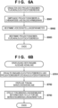
6A und6B zeigen Flussdiagramme, die auf einen Projektionsoberflächenleuchtdichtebereicherhaltebetrieb und einen Eingabe-Ausgabe-Kennlinienerzeugungsbetrieb gemäß dem ersten Ausführungsbeispiel bezogen sind.6A and6B show flowcharts related to a projection surface luminance range maintaining operation and an input-output characteristic generating operation according to the first embodiment. -
7A bis7D zeigen Diagramme, die beispielhafte Beziehungen zwischen einem Eingabeleuchtdichtebereich und dem Projektionsoberflächenleuchtdichtebereich zeigen.7A until7D show diagrams showing exemplary relationships between an input luminance range and the projection surface luminance range. -
8A bis8E zeigen Diagramme, die Beispiele der Eingabe-Ausgabe-Kennlinie zeigen, die in dem ersten Ausführungsbeispiel erzeugt wird.8A until8E -
9A und9B zeigen Flussdiagramme, die auf einen Projektionsoberflächenleuchtdichtebereicherhaltebetrieb gemäß den zweiten und dritten Ausführungsbeispielen bezogen sind.9A and9B show flowcharts related to a projection surface luminance range maintaining operation according to the second and third embodiments. -
10A und10B zeigen Diagramme, die auf einen Projektionsoberflächenleuchtdichtebereicherhaltebetrieb gemäß einem zweiten Ausführungsbeispiel bezogen sind.10A and10B show diagrams related to a projection surface luminance range maintaining operation according to a second embodiment. -
11A und11B zeigen Diagramme, die auf einen Projektionsentfernungsberechnungsbetrieb gemäß dem dritten Ausführungsbeispiel bezogen sind.11A and11B show diagrams related to a projection distance calculation operation according to the third embodiment.
BESCHREIBUNG DER AUSFÜHRUNGSBEISPIELEDESCRIPTION OF THE EMBODIMENTS
Beispielhafte Ausführungsbeispiele der vorliegenden Erfindung werden nachstehend ausführlich gemäß der beigefügten Zeichnung beschrieben.
Erstes AusführungsbeispielFirst embodiment
GesamtkonfigurationOverall configuration
Eine LCD-Projektionsvorrichtung 100 weist eine CPU 110, ein ROM 111, ein RAM 112, eine Bedienungseinheit 113, eine Bildeingabeeinheit 130 und eine Bildverarbeitungseinheit 140 auf. Die LCD-Projektionsvorrichtung 100 weist ebenso eine LCD-Steuerungseinheit 150, LCD-Vorrichtungen 151R, 151G und 151B, eine Lichtquellensteuerungseinheit 160, eine Lichtquelle 161, eine Farbtrennungseinheit 162, eine Farbzusammensetzungseinheit 163, eine Optisches-System-Steuerungseinheit 170 und ein optisches Projektionssystem 171 auf. Die LCD-Projektionsvorrichtung 100 kann ebenso eine Aufzeichnungs- und Wiedergabeeinheit 191, ein Aufzeichnungsmedium 192, eine Kommunikationseinheit 193, eine Bildaufnahmeeinheit 194, eine Anzeigesteuerungseinheit 195 und eine Anzeigeeinheit 196 aufweisen.An
Die CPU 110 steuert jeden funktionalen Block und realisiert die Funktionen der LCD-Projektionsvorrichtung 100, indem ein Programm beispielsweise in das RAM 112 geladen wird, wobei das Programm in einem nicht flüchtigen Speicher (beispielsweise dem ROM 111) gespeichert ist, und das geladene Programm ausgeführt wird. Programme, die durch die CPU 110 ausgeführt werden sollen, verschiedene eingestellte Werte, GUI-Daten, Produktinformationen und dergleichen sind in dem ROM 111 gespeichert, das zumindest teilweise wiederbeschreibbar sein kann. Das RAM 112 dient als ein Arbeitsspeicher für die CPU 110, wobei Programme und Daten zeitweilig in dem RAM 112 gespeichert werden.The
Standbilddaten und Bewegungsbilddaten, die von dem Aufzeichnungsmedium 192 durch die Aufzeichnungs- und Wiedergabeeinheit 191 wiedergegeben werden, können zeitweilig in der CPU 110 gespeichert werden, wobei die CPU 110 ebenso Bilder und Videos von den gespeicherten Daten unter Verwendung eines Programms, das in dem ROM 111 gespeichert ist, wiedergeben kann. Standbilddaten und Bewegungsbilddaten, die von der Kommunikationseinheit 193 empfangen werden, können zeitweilig in der CPU 110 gespeichert werden, wobei die CPU 110 ebenso Bilder und Videos von den gespeicherten Daten unter Verwendung eines Programms, das in dem ROM 111 gespeichert ist, wiedergeben kann. Bilder und Videos, die durch die Bildaufnahmeeinheit 194 erhalten werden, können zeitweilig in dem RAM 112 gespeichert werden und unter Verwendung eines Programms, das in dem ROM 111 gespeichert ist, in Standbilddaten und Bewegungsbilddaten umgewandelt werden sowie in dem Aufzeichnungsmedium 192 aufgezeichnet werden.Still image data and motion image data reproduced from the
Die Bedienungseinheit 113 wird beispielsweise durch einen Schalter, ein Wählfeld, ein Berührungsfeld beziehungsweise Touch-Panel, das auf der Anzeigeeinheit 196 bereitgestellt ist, oder dergleichen gebildet, wobei sie Anweisungen von dem Benutzer annimmt. Die Bedienungseinheit 113 kann beispielsweise eine Signalempfangseinheit zum Empfangen von Signalen von einer externen Vorrichtung, die als eine Fernsteuerungseinrichtung fungiert, aufweisen. Die CPU 110 führt Betriebe entsprechend einer Bedienung, die bei der Bedienungseinheit 113 ausgeführt wird, und der Eingabe von der Kommunikationseinheit 193 aus. Hierbei kann die externe Vorrichtung eine beliebige elektronische Vorrichtung sein, die in der Lage ist, ein Signal zu übertragen, das durch die Signalempfangseinheit empfangen werden kann und durch die CPU 110 erkannt werden kann. Beispiele einer derartigen elektronischen Vorrichtung umfassen einen Personalcomputer, eine Kamera, ein Mobiltelefon, ein Smartphone, einen Festplattenrekorder, eine Spielkonsole und dergleichen, wobei sie aber nicht hierauf begrenzt sind.The
Die Bildverarbeitungseinheit 140 wird beispielsweise durch einen Mikroprozessor für eine Bildverarbeitung gebildet, sie führt eine Verarbeitung zur Änderung der Anzahl von Einzelbilder beziehungsweise Rahmen, der Anzahl von Bildelementen beziehungsweise Pixeln, der Bildform oder dergleichen bei Videosignalen aus, die von der Bildeingabeeinheit 130 empfangen werden, und sie überträgt die verarbeiteten Videosignale zu der LCD-Steuerungseinheit 150. Die Bildverarbeitungseinheit 140 muss kein dedizierter Mikroprozessor sein, wobei beispielsweise die CPU 110 zumindest einige der Funktionen der Bildverarbeitung 140 realisieren kann, indem ein Programm ausgeführt wird, das in dem ROM 111 gespeichert ist. Die Bildverarbeitungseinheit 140 kann eine Einzelbildausdünnungsverarbeitung beziehungsweise Frame-Ausdünnungsverarbeitung, eine Einzelbildinterpolationsverarbeitung beziehungsweise Frame-Interpolationsverarbeitung, eine Auflösungsumwandlungsverarbeitung (Scaling-Verarbeitung), eine Verzerrungskorrekturverarbeitung (Trapezkorrekturverarbeitung) oder dergleichen bei Videosignalen ausführen, die beispielsweise in der Form von Bewegungsbildern eingegeben werden. Die Bildverarbeitungseinheit 140 kann ebenso die vorstehend genannte Verarbeitung ausführen, um Bilder und Videos zu ändern, die durch die CPU 110 wiedergegeben werden.The
Die LCD-Steuerungseinheit 150 steuert die Spannung, die an den Flüssigkristall von Bildelementen der Flüssigkristallelemente 151R, 151G und 151B anzulegen ist, auf der Grundlage der Videosignale, die durch die Bildverarbeitungseinheit 140 verarbeitet worden sind, wobei sie die Übertragungsfaktoren der LCD-Vorrichtungen 151R, 151G und 151B justiert. Es ist anzumerken, dass die LCD-Vorrichtungen 151R, 151G und 151B kollektiv als eine LCD-Vorrichtung 151 bezeichnet werden.The
Die LCD-Vorrichtung 151R ist eine LCD-Vorrichtung, die Rot entspricht, wobei sie verwendet wird, um den Übertragungsfaktor von rotem Licht in einem Licht zu justieren, das von der Lichtquelle 161 ausgegeben wird und in Rot (R), Grün (G) und Blau (B) durch die Farbtrennungseinheit 162 getrennt wird. Auf ähnliche Weise werden die LCD-Vorrichtungen 151G und die LCD-Vorrichtung 151B verwendet, um die Übertragungsfaktoren von grünem Licht beziehungsweise blauem Licht zu justieren.The
Die Lichtquellensteuerungseinheit 160 wird durch einen Steuerungsmikroprozessor gebildet und steuert die Lichtmenge sowie das Einschalten und Ausschalten der Lichtquelle 161. Es ist anzumerken, dass die Lichtquellensteuerungseinheit 160 kein dedizierter Mikroprozessor sein muss, wobei beispielsweise die CPU 110 zumindest einige der Funktionen der Lichtquellensteuerungseinheit 160 realisieren kann, indem ein Programm ausgeführt wird, das in dem ROM 111 gespeichert.The light
Die Lichtquelle 161 kann beispielsweise eine Halogenlampe, eine Xenonlampe, eine Hochdruckquecksilberlampe oder dergleichen sein, wobei sie Licht für ein Projizieren eines Bilds ausgibt. Die Lichttrennungseinheit 162 wird beispielsweise durch einen dichroitischen Spiegel, ein Prisma oder dergleichen gebildet und trennt das Licht, das von der Lichtquelle 161 ausgegeben wird, in rotes (R), grünes (G) und blaues (B) Licht. Es ist anzumerken, dass, wenn die Lichtquelle 161 rotes (R), grünes (G) und blaues (B) Licht ausgeben kann, die Farbtrennungseinheit 162 nicht erforderlich ist.The
Die Farbzusammensetzungseinheit 163 wird beispielsweise durch einen dichroitischen Spiegel, ein Prisma oder dergleichen gebildet und setzt das rote (R), grüne (G) und blaue (B) Licht, das durch die LCD-Vorrichtungen 151R, 151G und 151B hindurchgegangen ist, zusammen. Das Licht, das durch die Farbzusammensetzungseinheit 163 zusammengesetzt wird, geht in das optische Projektionssystem 171 hinein. Die Übertragungsfaktoren der LCD-Vorrichtungen 151R, 151G und 151B werden durch die LCD-Steuerungseinheit 150 gesteuert, um Werte zu sein, die einem Bild entsprechen, das von der Bildverarbeitungseinheit 140 eingegeben wird. Dementsprechend wird, wenn das Licht, das durch die Farbzusammensetzungseinheit 163 zusammengesetzt wird, durch das optische Projektionssystem 171 projiziert wird, das gleiche Bild wie das Bild, das durch die Bildverarbeitungseinheit 140 eingegeben wird, auf einer Projektionsoberfläche angezeigt.The
Die Optisches-System-Steuerungseinheit 170 wird durch einen Steuerungsmikroprozessor gebildet, wobei sie das optische Projektionssystem 171 steuert. Es ist anzumerken, dass die Optisches-System-Steuerungseinheit 170 kein dedizierter Mikroprozessor sein muss, wobei beispielsweise die CPU 110 zumindest einige der Funktionen der Optisches-System-Steuerungseinheit 170 verwirklichen kann, indem ein Programm ausgeführt wird, das in dem ROM 111 gespeichert ist.The optical
Das optische Projektionssystem 171 wird durch eine Vielzahl von Linsen und eine Betätigungseinrichtung zur Ansteuerung der Linsen gebildet und projiziert das zusammengesetzte Licht, das von der Farbzusammensetzungseinheit 163 aus eingetreten ist. Das projizierte Bild kann ein Hineinzoomen und Herauszoomen sowie einer Fokusjustierung oder dergleichen unterzogen werden, indem die Betätigungseinrichtung verwendet wird, um die Linsen in dem optischen Projektionssystem 171 anzusteuern, wobei die Linsen somit durch die Optisches-System-Steuerungseinheit 170 angesteuert werden.The projection
Eine Leuchtdichtebereicherhalteeinheit 181 (erste Erhalteeinheit) erhält Informationen, wie beispielsweise einen absoluten Leuchtdichtebereich, der eine Beziehung zwischen einem Farbtonwert beziehungsweise Tonwert eines Eingabewerts und einem absoluten Leuchtdichtewert definiert, von Metadaten (beispielsweise EXIF-Daten) oder von Kopfzeilen- beziehungsweise Header-Informationen, die Eingabebilddaten begleiten. Der absolute Leuchtdichtebereich kann aus Werten bestehen, die manuell durch den Benutzer unter Verwendung der Bedienungseinheit 113 eingegeben werden, anstelle von Werten, die von den Eingabebilddaten erhalten werden. Wenn der absolute Leuchtdichtebereich unter Verwendung von Werten ausgedrückt wird, können entweder Leuchtdichtewerte (Nit oder cd/m2) oder ein Reflexionsgrad (%) verwendet werden. In diesem Ausführungsbeispiel werden Leuchtdichtewerte (Nit) verwendet. Der absolute Leuchtdichtebereich, der durch die Leuchtdichtebereicherhalteeinheit 181 erhalten wird, gibt einen unteren Grenzwert und einen oberen Grenzwert an, wie beispielsweise „0 bis 2000 [Nit]“ oder „0 bis 10000 [Nit]“. Wenn jedoch der untere Grenzwert ein fixierter Wert ist, wie beispielsweise 0 [Nit] oder 0,005 [Nit], ist es ausreichend, dass zumindest der obere Grenzwert (maximale Leuchtdichte) erhaltbar ist.A luminance range obtaining unit 181 (first obtaining unit) obtains information such as an absolute luminance range defining a relationship between a hue value of an input value and an absolute luminance value from metadata (e.g. EXIF data) or from header information Accompany input image data. The absolute luminance range may consist of values manually entered by the user using the
Eine Projektionsoberflächenleuchtdichteerhalteeinheit 182 (zweite Erhalteeinheit) erhält den Projektionsoberflächenleuchtdichtebereich. Ein Verfahren zum Erhalten des Projektionsoberflächenleuchtdichtebereichs wird nachstehend beschrieben.A projection surface luminance obtaining unit 182 (second obtaining unit) obtains the projection surface luminance area. A method of obtaining the projection surface luminance range will be described below.
Die Aufzeichnungs- und Wiedergabeeinheit 191 liest Standbilddaten und Bewegungsbilddaten von dem Aufzeichnungsmedium 192 aus, um die ausgelesenen Bilddaten wiederzugeben, und empfängt von der CPU 110 Standbilddaten und Bewegungsbilddaten, die durch die Bildaufnahmeeinheit 194 erhalten werden, und zeichnet die empfangenen Bilddaten in dem Aufzeichnungsmedium 192 auf. Die Aufzeichnungs- und Wiedergabeeinheit 191 kann ebenso in dem Aufzeichnungsmedium 192 Standbilddaten und Bewegungsbilddaten aufzeichnen, die über die Kommunikationseinheit 193 empfangen werden. Die Aufzeichnungs- und Wiedergabeeinheit 191 weist beispielsweise eine Schnittstelle für einen Zugriff auf das Aufzeichnungsmedium 192 und einen Mikroprozessor für ein Kommunizieren mit dem Aufzeichnungsmedium 192 auf. Wenn das Aufzeichnungsmedium 192 ein entfernbares Medium ist, weist die Aufzeichnungs- und Wiedergabeeinheit 191 ebenso einen Mechanismus, wie beispielsweise einen Schlitz, für ein entfernbares Halten des Aufzeichnungsmediums 192 auf. Es ist anzumerken, dass die Aufzeichnungs- und Wiedergabeeinheit 191 keinen dedizierten Mikroprozessor aufweisen muss, wobei beispielsweise die CPU 110 zumindest einige der Funktionen der Aufzeichnungs- und Wiedergabeeinheit 191 verwirklichen kann, indem ein Programm ausgeführt wird, das in dem ROM 111 gespeichert wird. Daten, die zu Standbilddaten und Bewegungsbilddaten unterschiedlich sind, wie beispielsweise Steuerungsdaten für die LCD-Projektionsvorrichtung 100 gemäß diesem Ausführungsbeispiel, können ebenso in dem Aufzeichnungsmedium 192 aufgezeichnet werden. Das Aufzeichnungsmedium 192 kann ein Aufzeichnungsmedium in einem beliebigen Format sein, wie beispielsweise eine Magnetplatte, eine optische Platte oder ein Halbleiterspeicher, und kann entweder entfernbar oder fixiert in Bezug auf die LCD-Projektionsvorrichtung 100 sein.The recording and reproducing
Die Kommunikationseinheit 193 kommuniziert Steuerungssignale, Standbilddaten, Bewegungsbilddaten oder dergleichen mit einer externen Vorrichtung entsprechend der Steuerung, die durch die CPU 110 ausgeführt wird. Es gibt keine Begrenzung bezüglich Kommunikationsverfahren oder Standards, wobei beispielsweise eine Kommunikation, die mit einem oder mehreren aus einem drahtlosen LAN, einem verdrahteten LAN, USB, Bluetooth (registrierte Handelsmarke) und dergleichen übereinstimmt, ausgeführt werden kann. Es ist anzumerken, dass, wenn die Bildeingabeeinheit 130 HDMI (registrierte Handelsmarke) entspricht, die Kommunikationseinheit 193 eine CEC-Kommunikation mit einer externen Vorrichtung ausführen kann, die mit der Bildeingabeeinheit 130 verbunden ist. Wenn beispielsweise ein Anschluss der Bildeingabeeinheit 130 ein HDMI-Anschluss (registrierte Handelsmarke) ist, kann eine CEC-Kommunikation (CEC: Consumer Electronic Control) über diesen Anschluss ausgeführt werden. Hierbei kann die externe Vorrichtung irgendeine elektronische Vorrichtung sein, die in der Lage ist, mit der LCD-Projektionsvorrichtung 100 zu kommunizieren, wobei sie beispielsweise ein Personalcomputer, eine Kamera, ein Mobiltelefon, ein Smartphone, eine Festplattenaufzeichnungsvorrichtung, eine Spielkonsole, eine Fernsteuerung oder dergleichen sein kann.The
Die Bildeingabeeinheit 130 umfasst eine Schnittstelle hauptsächlich zum Empfangen von Bildsignalen von der externen Vorrichtung. Dementsprechend kann die Bildeingabeeinheit 130 eine oder mehrere von bekannten Videoeingabeschnittstellen aufweisen, wie beispielsweise D-Sub, DVI-D, DVI-I, HDMI, Display-Port, USB, Composite, S-Video, Component und D1 bis D5.The
Die Bildaufnahmeeinheit 194 ist konfiguriert und angeordnet, um in der Lage zu sein, die Projektionsoberfläche der LCD-Projektionsvorrichtung 100 aufzunehmen, und überträgt das aufgenommene Bild zu der CPU 110. Die CPU 110 speichert zeitweilig in dem RAM 112 das Bild, das durch die Bildaufnahmeeinheit 194 erhalten wird, und wandelt das gespeicherte Bild in Standbilddaten oder Bewegungsbilddaten auf der Grundlage eines Programms um, das in dem ROM 111 gespeichert ist. Die Bildaufnahmeeinheit 194 weist Bildaufnahmelinsen beziehungsweise Abbildungslinsen zum Bilden eines optischen Bilds eines Objekts, eine Betätigungseinrichtung zum Ansteuern einer Fokussierungslinse und einer Zoomlinse, die in den Abbildungslinsen beinhaltet sind, einen Mikroprozessor zur Steuerung der Betätigungseinrichtung und einen Bildsensor zur Umwandlung des optischen Bilds, das durch die Abbildungslinsen gebildet wird, in ein Bildsignal auf. Die Bildaufnahmeeinheit 194 kann ebenso eine AD-Umwandlungseinheit zur Umwandlung eines analogen Bildsignals, das durch den Bildsensor ausgegeben wird, in ein digitales Bildsignal aufweisen. Es ist anzumerken, dass die Bildaufnahmeeinheit 194 nicht auf eine für ein Aufnehmen der Projektionsoberfläche begrenzt ist, wobei sie beispielsweise ebenso eine für ein Aufnehmen der Seite, die entgegengesetzt zu der Seite ist, auf der die Projektionsoberfläche ist, sein kann.The
Die Anzeigesteuerungseinheit 195 weist beispielsweise einen Mikroprozessor auf und veranlasst die Anzeigeeinheit 196, einen Bedienungsbildschirm für ein Bedienen der LCD-Projektionsvorrichtung 100 und von GUI-Bildern, wie beispielsweise ein Schaltersymbol, anzuzeigen. Es ist anzumerken, dass die Anzeigesteuerungseinheit 195 kein dedizierter Mikroprozessor sein muss, wobei beispielsweise die CPU 110 zumindest einige der Funktionen der Anzeigesteuerungseinheit 195 realisieren kann, indem ein Programm ausgeführt wird, das in dem ROM 111 gespeichert ist.The
Die Anzeigeeinheit 196 kann eine Anzeigevorrichtung in einer beliebigen Form sein, wie beispielsweise eine LCD, eine CRT-Anzeige, eine organische EL-Anzeige oder eine LED-Anzeige. Die Anzeigeeinheit 196 ist nicht auf eine Matrixanzeige begrenzt, wobei sie beispielsweise lichtemittierende Elemente umfassen kann, die in einem Knopf, einem Schalter oder dergleichen eingebaut sind.The
Es ist anzumerken, dass die Bildverarbeitungseinheit 140, die LCD-Steuerungseinheit 150, die Lichtquellensteuerungseinheit 160, die Optisches-System-Steuerungseinheit 170, die Aufzeichnungs- und Wiedergabeeinheit 191 und die Anzeigesteuerungseinheit 195 gemäß diesem Ausführungsbeispiel ein einzelner Mikroprozessor oder mehrere Mikroprozessoren sein können, der/die in der Lage ist/sind, die gleiche Verarbeitung wie die Verarbeitung gemäß dieser Blöcke auszuführen. Alternativ hierzu kann beispielsweise die CPU 110 zumindest einige der Funktionen von einem oder mehreren funktionalen Blöcken, die keinen Prozessor aufweisen, realisieren, indem ein Programm ausgeführt wird, das in dem ROM 111 gespeichert ist.It is to be noted that the
GrundbetriebBasic operation
Ein Grundbetrieb der LCD-Projektionsvorrichtung 100 gemäß diesem Ausführungsbeispiel wird unter Verwendung eines Flussdiagramms beschrieben, das in
Wenn die Anweisung zum Einschalten der Leistung eingegeben ist, veranlasst die CPU 110 eine (nicht gezeigte) Leistungszufuhreinheit, eine Leistung zu jeder Einheit der LCD-Projektionsvorrichtung 100 zuzuführen.When the instruction to turn on the power is input, the
Als Nächstes bestimmt die CPU 110 die Anzeigebetriebsart der LCD-Projektionsvorrichtung 100 (S210). Die Anzeigebetriebsart wird beispielsweise über die Bedienungseinheit 113 oder eine externe Vorrichtung bestimmt, wobei die Anzeigebetriebsart der LCD-Projektionsvorrichtung 100 gemäß diesem Ausführungsbeispiel eine aus einer „Eingabebildanzeigebetriebsart“, einer „Wiedergegebene-Datei-Anzeigebetriebsart“ und einer „Empfangene-Datei-Anzeigebetriebsart“ ist, wobei sie nicht hierauf begrenzt ist. In der „Eingabebildanzeigebetriebsart“ zeigt die LCD-Projektionsvorrichtung 100 ein Bild an, das auf einem Videosignal beruht, das von der Bildeingabeeinheit 130 eingegeben wird. In der „Wiedergegebene-Datei-Anzeigebetriebsart“ zeigt die LCD-Projektionsvorrichtung 100 ein Bild an, das auf Daten beruht, die von dem Aufzeichnungsmedium 192 durch die Aufzeichnungs- und Wiedergabeeinheit 191 ausgelesen werden. In der „Empfangene-Datei-Anzeigebetriebsart“ zeigt die LCD-Projektionsvorrichtung 100 ein Bild an, das auf Daten beruht, die von der Kommunikationseinheit 193 empfangen werden. Es ist anzumerken, dass die Anzeigebetriebsart, wenn die Leistung eingeschaltet wird, die Anzeigebetriebsart sein kann, die zuletzt verwendet worden ist, als die Projektionsvorrichtung ausgeschaltet worden ist, oder eine vorbestimmte Anzeigebetriebsart sein kann. In diesem Fall muss die Anzeigebetriebsart nicht notwendigerweise durch den Benutzer bestimmt werden.Next, the
Nachstehend wird eine Beschreibung des Falls angegeben, in dem die Anzeigebetriebsart die „Eingabebildanzeigebetriebsart“ entsprechend dem Bestimmungsergebnis in Schritt S210 ist.A description will be given below of the case where the display mode is the “input image display mode” according to the determination result in step S210.
In dem Fall der „Eingabebildanzeigebetriebsart“ bestimmt die CPU 110, ob ein Videosignal von der Bildeingabeeinheit 130 eingegeben worden ist (S220), wobei sie wartet, wenn nicht bestimmt wird, dass ein Videosignal eingegeben worden ist, oder die Verarbeitung zu Schritt S230 voranbringt, wenn bestimmt wird, dass ein Videosignal eingegeben worden ist.In the case of the "input image display mode", the
In Schritt S230 führt die CPU 110 eine Projektionsverarbeitung aus. Die CPU 110 überträgt das Videosignal, das von der Bildeingabeeinheit 130 eingegeben worden ist, zu der Bildverarbeitungseinheit 140 und veranlasst die Bildverarbeitungseinheit 140, ein Bild für einen Bildschirm zu erzeugen. Die Bildverarbeitungseinheit 140 wendet die notwendige Transformationsverarbeitung (beispielsweise bezüglich der Anzahl von Bildelementen beziehungsweise Pixeln, der Einzelbildrate beziehungsweise Rahmenrate und der Form) bei dem Videosignal an, erzeugt ein Bild für einen Bildschirm und überträgt das erzeugte Bild zu der LCD-Steuerungseinheit 150. Die LCD-Steuerungseinheit 150 steuert die Übertragungsfaktoren von jeweiligen Bildelementen beziehungsweise Pixeln der LCD-Vorrichtungen 151R, 151G und 151B, um die Übertragungsfaktoren zu erhalten, die den Farbtonpegeln beziehungsweise Tonpegeln der jeweiligen roten (R), grünen (G), und blauen (B) Farbkomponenten der Bildelemente beziehungsweise Pixel des empfangenden Bilds für einen Bildschirm entsprechen.In step S230, the
Die Lichtquellensteuerungseinheit 160 steuert die Ausgabe von Licht von der Lichtquelle 161 auf der Grundlage der peripheren Helligkeit, die auf dem Bild beruht, das beispielsweise durch die Bildaufnahmeeinheit 194 erhalten wird. Das Licht, das von der Lichtquelle 161 ausgegeben wird, wird in rotes (R), grünes (G) und blaues (B) Licht durch die Farbtrennungseinheit 162 getrennt und als eine Lichtquelle für die LCD-Vorrichtungen 151R, 151G und 151B zugeführt. Das Licht der jeweiligen Farben, für die die Übertragungsfaktoren für die jeweilige Bildelemente beziehungsweise Pixel der LCD-Vorrichtungen 151R, 151G und 151B gesteuert worden sind, wird durch die Farbzusammensetzungseinheit 163 zusammengesetzt und über das optische Projektionssystem 171 projiziert.The light
Die CPU 110 steuert eine Abfolge von Betrieben in diesen Einheiten während der Projektionsverarbeitung. Die Projektionsverarbeitung wird sequenziell ausgeführt, bis eine Videosignaleingabe nicht länger erfasst wird oder eine Anweisung zum Beenden einer Anzeige gegeben wird.The
Es ist anzumerken, dass, wenn eine Anweisung zum Ändern des Bildwinkels (Vergrößerungsverhältnis) oder des Fokus des optischen Projektionssystems 171 von der Bedienungseinheit 113 während der Verarbeitung in den Schritten S220 bis S250 eingegeben wird, die CPU 110 die Betätigungseinrichtung, die in dem optischen Projektionssystem 171 bereitgestellt ist, entsprechend der Anweisung ansteuert.It should be noted that when an instruction to change the angle of view (magnification ratio) or the focus of the projection
In Schritt S240 bestimmt die CPU 110, ob eine Anweisung zum Umschalten der Anzeigebetriebsart von der Bedienungseinheit 113 eingegeben worden ist, wobei sie die Verarbeitung zu Schritt S210 zurückführt, wenn bestimmt wird, dass eine Anweisung eingegeben worden ist, oder die Verarbeitung zu Schritt S250 voranbringt, wenn nicht bestimmt wird, dass eine Anweisung eingegeben worden ist. Es ist anzumerken, dass in dem Fall eines Zurückführens der Verarbeitung zu Schritt S210 die CPU 110 einen Menübildschirm für eine Anzeigebetriebsartauswahl als ein OSD-Bild zu der Bildverarbeitungseinheit 140 überträgt wobei sie die Bildverarbeitungseinheit 140 steuert, den Menübildschirm anzuzeigen, um den Menübildschirm auf einem derzeit projizierten Bild zu überlagern. Der Benutzer kann den Menübildschirm, der in einer überlagerten Art und Weise angezeigt wird, unter Verwendung der Bedienungseinheit 113 betätigen und eine gewünschte Anzeigebetriebsart auswählen.In step S240, the
Demgegenüber bestimmt in Schritt S250 die CPU 110, ob eine Anweisung zum Beenden der Projektion von der Bedienungseinheit 113 eingegeben worden ist, wobei sie die Verarbeitung zu Schritt S220 zurückführt, wenn nicht bestimmt wird, dass eine Anweisung eingegeben worden ist, oder eine Leistungszufuhr von der Leistungszufuhreinheit stoppt, um jeweils die Verarbeitung zu blockieren und zu beenden, wenn bestimmt wird, dass eine Anweisung eingegeben worden ist. Mit dem vorstehend beschriebenen Betrieb projiziert die LCD-Projektionsvorrichtung 100 in der Eingabebildanzeigebetriebsart ein Bild auf der Grundlage des Videosignals, das von der Bildeingabeeinheit 130 eingegeben wird.On the other hand, in step S250, the
Es ist anzumerken, dass, wenn in Schritt S210 bestimmt wird, dass die Anzeigebetriebsart die „wiedergegebene Datei-Anzeigebetriebsart“ ist, die CPU 110 die Aufzeichnungs- und Wiedergabeeinheit 191 veranlasst, eine Dateiliste oder Miniaturbilddaten jeder Datei in dem Aufzeichnungsmedium 192 auszulesen, wobei sie die ausgelesene Dateiliste oder die Miniaturbilddaten in dem RAM 112 zeitweilig speichert. Die CPU 110 erzeugt dann Dateiauswahlbildschirmdaten auf der Grundlage eines Textzeichenbildes, das auf der Dateiliste beruht, die zeitweilig in dem RAM 112 gespeichert ist, oder der Miniaturbilddaten jeder Datei, wobei sie die erzeugten Dateiauswahlbildschirmdaten zu der Bildverarbeitungseinheit 140 überträgt. Der Dateiauswahlbildschirm wird durch die gleiche Verarbeitung wie die Projektionsverarbeitung projiziert (S230).Note that when it is determined in step S210 that the display mode is the “reproduced file display mode”, the
Wenn eine Anweisung zum Auswählen einer spezifischen Bilddatei von dem Dateiauswahlbildschirm über die Bedienungseinheit 113 oder eine externe Vorrichtung eingegeben wird, steuert die CPU 110 die Aufzeichnungs- und Wiedergabeeinheit 191, um die ausgewählte Bilddatei wiederzugeben.When an instruction to select a specific image file is input from the file selection screen via the
Die Bilddaten, die von der Bilddatei wiedergegeben werden, werden von der Aufzeichnungs- und Wiedergabeeinheit 191 zu der Bildverarbeitungseinheit 140 übertragen und durch die gleiche Projektionsverarbeitung wie die in Schritt S230 durch die Bildverarbeitungseinheit 140, die LCD-Steuerungseinheit 150 und die Lichtquellensteuerungseinheit 160 projiziert. Wenn ein Bewegungsbild wiedergegeben werden soll, wird eine Wiedergabe- und Projektionsverarbeitung sequenziell für jedes Einzelbild beziehungsweise für jeden Rahmen ausgeführt. Die CPU 110 führt den Betrieb, der in dem Fall ausgeführt wird, in dem ein Betrieb durchgeführt worden ist, der auf das optische Projektionssystem 171 bezogen ist, und die Betriebe, die in den Schritten S240 und S250 angegeben sind, in der gleichen Art und Weise wie in der Eingabebildanzeigebetriebsart aus.The image data reproduced from the image file is transmitted from the recording and reproducing
Wenn in Schritt S210 bestimmt wird, dass die Anzeigebetriebsart die „Empfangende-Datei-Anzeigebetriebsart“ ist, projiziert die CPU 110 Standbilddaten oder Bewegungsbilddaten, die von der Kommunikationseinheit 193 empfangen werden, in der gleichen Art und Weise wie die Bilddaten, die durch die Aufzeichnungs- und Wiedergabeeinheit 191 in der Wiedergegebene-Datei-Anzeigebetriebsart wiedergegeben werden. Die CPU 110 führt den Betrieb, der in dem Fall ausgeführt wird, in dem ein Betrieb durchgeführt worden ist, der das optische Projektionssystem 171 betrifft, und die Betriebe, die in den Schritten S240 und S250 angegeben sind, in der gleichen Art und Weise wie in der Eingabebildanzeigebetriebsart aus.When it is determined in step S210 that the display mode is the “receiving file display mode”, the
Als Nächstes wird unter Verwendung der
Nachstehend wird eine Beschreibung des Falls angegeben, in dem die Anzeigebetriebsart der LCD-Projektionsvorrichtung 100 die Eingabebildanzeigebetriebsart ist, wobei ein Videosignal eines HDR-Bilds, in dem der dynamische Bereich unter Verwendung einer Transferfunktion (EOTF) zur Angabe der absoluten Leuchtdichte ausgedrückt wird, wie in dem ST.2084-Standard, der Bildeingabeeinheit 130 eingegeben wird. Die gleiche Anzeigeverarbeitung kann jedoch ebenso in dem Fall ausgeführt werden, in dem ähnliche HDR-Bilddaten aus dem Aufzeichnungsmedium 192 ausgelesen werden oder über die Kommunikationseinheit 193 empfangen werden. In dem Fall, in dem die Bildeingabeeinheit 130 eine Schnittstelle zur Übertragung von digitalen Signalen, wie beispielsweise eine Schnittstelle, die HDMI entspricht, aufweist, werden Videosignale in einem digitalen Format eingegeben. Aus diesem Grund wird ein Videosignal eines HDR-Bilds, das der Bildeingabeeinheit 130 eingegeben wird, nachstehend als HDR-Bilddaten bezeichnet, wie in dem Fall von Bilddaten, die von dem Aufzeichnungsmedium 192 ausgelesen werden.A description will be given below of the case in which the display mode of the
Die HDR-Bilddaten, die von der Bildeingabeeinheit 130 eingegeben werden, werden zuerst durch eine lineare Umwandlungseinheit 141 in der Bildverarbeitungseinheit 140 umgewandelt, um eine lineare Eingabe-Ausgabe-Kennlinie zu erhalten. Beispielsweise wandelt, wenn der maximale Farbtonwert beziehungsweise Tonwert des Bilds 1023 ist (10-Bit-Bild) und mit einer absoluten Leuchtdichte von 2000 Nit verbunden ist, die lineare Umwandlungseinheit 141 den Tonwert um, um eine lineare Beziehung zu erhalten, in der die absolute Leuchtdichte 1000 Nit ist, wenn der Tonwert 512 ist, und die absolute Leuchtdichte 0 Nit ist, wenn der Tonwert 0 ist. In dem Fall, in dem der Tonwert und der Leuchtdichtewert somit in einer linearen Beziehung stehen, wird dies eine lineare Leuchtdichtekennlinie genannt.The HDR image data input from the
Die HDR-Bilddaten, die durch die lineare Umwandlungseinheit 141 umgewandelt worden sind, um eine lineare Leuchtdichtekennlinie aufzuweisen, werden einer Bereichsumwandlungseinheit 142 eingegeben. Die Bereichsumwandlungseinheit 142 korrigiert die HDR-Bilddaten beispielsweise unter Verwendung einer eindimensionalen Nachschlagetabelle (1D-LUT), und führt die korrigierten HDR-Bilddaten einer Gammaumwandlungseinheit 143 zu. Die Gammaumwandlungseinheit 143 korrigiert entsprechend einer Gammakennlinie der LCD-Vorrichtung 151 die korrigierten HDR-Bilddaten in Gammaraumdaten, um mit der linearen Leuchtdichtekennlinie angezeigt zu werden (Gammakorrektur), und führt die gammakorrigierten HDR-Bilddaten der LCD-Steuerungseinheit 150 zu.The HDR image data converted by the
Die Einzelheiten des Betriebs werden unter Bezugnahme auf
In Schritt S401 liest die Leuchtdichtebereicherhalteeinheit 181 EXIF-Daten oder Kopfzeilen- beziehungsweise Header-Informationen der Bilddaten aus, die der Bildeingabeeinheit 130 eingegeben worden sind, sie bestimmt, ob absolute Leuchtdichtebereichdaten bezüglich des Eingabebilds vorhanden sind, und sie benachrichtigt die CPU 110 über das Bestimmungsergebnis. Diese Bestimmung dient ebenso als eine Bestimmung dahingehend, ob das Eingabebild ein HDR-Bild ist, und kann eine Bestimmung dahingehend sein, ob der bestimmte Transferfunktionstyp eine Transferfunktion angibt, die einen absoluten Leuchtdichtebereich verwendet. Die CPU 110 führt die Verarbeitung zu Schritt S402 voran, wenn die Leuchtdichtebereicherhalteeinheit 181 bestimmt, dass die absoluten Leuchtdichtebereichdaten bezüglich des Eingabebilds vorhanden sind, oder sie führt die Verarbeitung zu Schritt S408 voran, wenn dies nicht der Fall ist.In step S401, the luminance
In Schritt S408 führen die CPU 110, die Bildverarbeitungseinheit 140, die LCD-Steuerungseinheit 150 und die Lichtquellensteuerungseinheit 160 einen Betrieb zum Projizieren der Bilddaten (SDR-Bilddaten) aus, die einen normalen dynamischen Bereich aufweisen, wie beispielsweise sRGB. In diesem Fall, muss lediglich die gleiche Verarbeitung wie die in den Schritten S220 bis S250 gemäß
Es ist anzumerken, dass, wenn in Schritt S401 durch die Leuchtdichtebereicherhalteeinheit 181 bestimmt wird, dass EXIF-Daten oder Kopfzeilen- beziehungsweise Header-Informationen an sich nicht vorhanden sind, die CPU 110 veranlassen kann, dass ein Eingabeeinstellungsbildschirm wie beispielsweise einer, der in
Auf dem Eingabeeinstellungsbildschirm, der in
In Schritt S402 überträgt die CPU 110 die eingestellte Projektionsgröße und den eingestellten Bildschirmgewinn zu der Projektionsoberflächenleuchtdichteerhalteeinheit 182. Die Projektionsoberflächenleuchtdichteerhalteeinheit 182 berechnet den Projektionsoberflächenleuchtdichtebereich unter Verwendung der empfangenen Projektionsgröße und des Bildschirmgewinns, wobei sie den berechneten Projektionsoberflächenleuchtdichtebereich zu der CPU 110 überträgt. Die Einzelheiten hiervon werden nachstehend unter Verwendung eines Flussdiagramms in
In Schritt S403 erzeugt die CPU 110 eine Eingabe-Ausgabe-Kennlinie (Farbtonumwandlungskennlinie beziehungsweise Tonumwandlungskennlinie) des Tonwerts, die durch die Bereichsumwandlungseinheit 142 anzuwenden ist, auf der Grundlage des Eingabeleuchtdichtebereichs, der von der Leuchtdichtebereicherhalteeinheit 181 (oder dem Eingabeeinstellungsbildschirm) erhalten wird, und des Projektionsoberflächenleuchtdichtebereichs, der von der Projektionsoberflächenleuchtdichteerhalteeinheit 182 erhalten wird. Die CPU 110 stellt dann die eingestellte Eingabe-Ausgabe-Kennlinie auf eine 1D-LUT ein, die die Bereichsumwandlungseinheit 142 aufweist. Die Einzelheiten hiervon werden nachstehend unter Bezugnahme auf ein Flussdiagramm gemäß
In Schritt S404 wird eine Bildverarbeitung, die durch die lineare Umwandlungseinheit 141, die Bereichsumwandlungseinheit 142 und die Gammaumwandlungseinheit 143 ausgeführt wird, bei den Eingabebilddaten angewendet, wobei diese Bilddaten an die LCD-Steuerungseinheit 150 ausgegeben werden.In step S404, image processing performed by the
In Schritt S405 steuert die LCD-Steuerungseinheit 150 die Übertragungsfaktoren der LCD-Vorrichtungen 151R, 151G und 151B entsprechend den Bilddaten, die von der Bildverarbeitungseinheit 141 (der Gammaumwandlungseinheit 143) eingegeben werden.In step S405, the
In Schritt S406 überprüft die CPU 110 den Wert eines Neujustierungskennzeichens beziehungsweise Neujustierungsflags, wobei sie die Verarbeitung zu Schritt S402 zurückführt, wenn der Wert 1 ist (das heißt, das Flag ist EIN), oder die Verarbeitung beendet (das heißt die Verarbeitung zu Schritt S240 voranführt), wenn der Wert 0 ist (das heißt, wenn das Flag AUS ist). In diesem Ausführungsbeispiel ist das Neujustierungsflag auf 1 gesetzt, wenn die Projektionsgröße oder der Bildschirmgewinn bei dem Eingabeeinstellungsbildschirm in
Somit wird eine Projektionsverarbeitung für ein Einzelbild beziehungsweise einen Rahmen ausführt wird. Es ist anzumerken, dass die Verarbeitung in Schritten S402 und S403 nicht in jeder Projektionsverarbeitung für ein Einzelbild beziehungsweise einen Rahmen ausgeführt werden kann.Thus, projection processing is carried out for a frame or a frame. It should be noted that the processing in steps S402 and S403 cannot be carried out in each projection processing for a frame or a frame.
Als Nächstes wird der Betrieb zum Erhalten des Projektionsoberflächenleuchtdichtebereichs, der in Schritt S402 ausgeführt wird, unter Verwendung des Flussdiagramms beschrieben, das in
In Schritt S501 empfängt die Projektionsoberflächenleuchtdichteerhalteeinheit 182 die eingestellte Projektionsgröße und den eingestellten Bildschirmgewinn von der CPU 110.In step S501, the projection surface
In Schritt S502 bestimmt die Projektionsoberflächenleuchtdichteerhalteeinheit 182 den Wert eines Videoeinstellungsparameters. In dem Fall, in dem die Lichtmenge aufgrund der Einstellungen nicht variiert, muss Schritt S502 nicht ausgeführt werden. Der Videoeinstellungsparameter ist ein Koeffizient für die Lichtmenge und weist einen Wert auf, der zu 1 unterschiedlich ist, wenn die Projektionsvorrichtungslichtmenge aufgrund der Einstellungen variiert. In der LCD-Projektionsvorrichtung 100 gemäß diesem Ausführungsbeispiel beeinflussen eingestellte Werte für die „Projektionsbetriebsart“, die „Helligkeit“, den „Kontrast“, „Gamma“ und die „Lampenbetriebsart“ unter einstellbaren Elementen auf dem Videoeinstellungsbildschirm, der in
Es ist anzumerken, dass beispielsweise entweder eine „Präsentationsbetriebsart“ oder eine „Standardbetriebsart“ als die „Projektionsbetriebsart“ eingestellt sein kann. Hierbei wird angenommen, dass die „Präsentationsbetriebsart“ einem Videoeinstellungsparameter von 1 entspricht, wobei die „Standardbetriebsart“ einem Videoeinstellungsparameter eines Werts entspricht, der kleiner als in der „Präsentationsbetriebsart“ ist (beispielsweise 0,9). Als die „Lampenbetriebsart“ kann entweder „normal“ oder „Energie sparen“ eingestellt werden, wobei angenommen wird, dass „normal“ und „Energie sparen“ jeweils einem Videoeinstellungsparameter von 1 und einem Videoeinstellungsparameter eines Werts entsprechen, der kleiner als in dem Fall von „normal“ ist (beispielsweise 0,9). Auch für die anderen Elemente wird die Beziehung zwischen einstellbaren Werten und einem entsprechenden Videoeinstellungsparameter im Voraus bestimmt. Dementsprechend kann die Projektionsoberflächenleuchtdichteerhalteeinheit 182 den abschließenden Wert eines Videoeinstellungsparameters bestimmen, indem die eingestellten Werte jedes Elements mit dem entsprechenden Wert des Videoeinstellungsparameters multipliziert wird. Es ist anzumerken, dass die Typen der eingestellten Elemente, die die Lichtmenge und die Beziehung zwischen eingestellten Werten und dem Videoeinstellungsparameter beeinflussen, der vorstehend beschrieben ist, lediglich Beispiele sind, wobei sie nicht hierauf begrenzt sind. Der abschließende Wert eines Videoeinstellungsparameters kann alternativ hierzu unter Verwendung anderer Verfahren erhalten werden, beispielsweise indem auf eine Übereinstimmung zwischen Kombinationen der eingestellten Werte und dem Wert des Videoeinstellungsparameters Bezug genommen wird, die im Voraus gespeichert wird.It should be noted that, for example, either a “presentation mode” or a “standard mode” may be set as the “projection mode”. Here, it is assumed that the "Presentation Mode" corresponds to a video setting parameter of 1, where the "Standard Mode" corresponds to a video setting parameter of a value that is smaller than in the "Presentation Mode" (e.g. 0.9). As the "lamp mode", either "normal" or "power save" can be set, assuming that "normal" and "power save" respectively correspond to a video setting parameter of 1 and a video setting parameter of a value smaller than in the case of is “normal” (e.g. 0.9). For the other elements, the relationship between adjustable values and a corresponding video setting parameter is also determined in advance. Accordingly, the projection surface
In Schritt S503 berechnet die Projektionsoberflächenleuchtdichteerhalteeinheit 182 die Projektionsoberflächenleuchtdichte beispielsweise entsprechend einer nachstehend genannten Gleichung 1 auf der Grundlage der vorbestimmten Projektionsvorrichtungslichtmenge, der Projektionsgröße und des Bildschirmgewinns, die in Schritt S501 empfangen werden, und des Videoeinstellungsparameters, der in Schritt S502 bestimmt wird. Es ist anzumerken, dass, wenn die Projektionsgröße in Einheiten von Zoll ist, die Projektionsoberflächenleuchtdichteerhalteeinheit 182 die Projektionsgröße in Quadratmeter umwandelt und die umgewandelte Projektionsgröße bei Gleichung 1 anwendet. 
Hierbei kann die Projektionsvorrichtungslichtmenge ein Spezifikationswert sein (beispielsweise ein gemessener Wert unter JIS X 6911:2015). In dem Fall, in dem die Lichtmenge aufgrund der Einstellungen variiert, wird eine vorbestimmte Referenzlichtmenge angewendet. Die maximale Leuchtdichte auf der Projektionsoberfläche, die mit den derzeitigen Einstellungen erreicht wird, wird auf der Grundlage der Gleichung 1 erhalten.Here, the projection device light amount may be a specification value (for example, a measured value under JIS X 6911:2015). In the case where the amount of light varies due to the settings, a predetermined reference amount of light is applied. The maximum luminance on the projection surface achieved with the current settings is obtained based on
In diesem Ausführungsbeispiel wird die Projektionsoberflächenleuchtdichte zu der Zeit eines vollweißen Bildschirms (wenn alle Bildelemente beziehungsweise Pixel ein Bild projizieren, das den maximalen Tonwert aufweist) (maximale Leuchtdichte) unter Verwendung der Gleichung 1 berechnet, wobei die Projektionsoberflächenleuchtdichte zu der Zeit eines vollschwarzen Bildschirms (wenn alle Bildelemente beziehungsweise Pixel ein Bild eines Tonwerts von 0 projizieren) 0 [Nit] ist. Der Projektionsoberflächenleuchtdichtebereich wird durch die Projektionsoberflächenleuchtdichte zu der Zeit eines vollweißen Bildschirms (maximale Leuchtdichte) und die Projektionsoberflächenleuchtdichte zu der Zeit eines vollschwarzen Bildschirms (minimale Leuchtdichte) bestimmt. Die Projektionsoberflächenleuchtdichteerhalteeinheit 182 benachrichtigt die CPU 110 über den Projektionsoberflächenleuchtdichtebereich. Es ist anzumerken, dass, wenn die minimale Leuchtdichte, die den Projektionsoberflächenleuchtdichtebereich definiert immer 0 [Nit] ist, die Projektionsoberflächenleuchtdichteerhalteeinheit 182 die CPU 110 lediglich über die maximale Leuchtdichte benachrichtigen kann.In this embodiment, the projection surface luminance at the time of a full white screen (when all pixels project an image having the maximum tonal value) (maximum luminance) is calculated using
Als Nächstes werden die Einzelheiten des Betriebs zur Erzeugung der Eingabe-Ausgabe-Kennlinie in Schritt S403 unter Verwendung des Flussdiagramms gemäß
In Schritt S701 erhält die CPU 110 den Eingabeleuchtdichtebereich und den Projektionsoberflächenleuchtdichtebereich von der Leuchtdichtebereicherhalteeinheit 181 (oder dem Eingabeeinstellungsbildschirm) beziehungsweise der Projektionsoberflächenleuchtdichteerhalteeinheit 182.In step S701, the
In Schritt S702 erzeugt die CPU 110 die Eingabe-Ausgabe-Kennlinie des Tonwerts, der in der 1D-LUT in der Bereichsumwandlungseinheit 142 einzustellen ist, auf der Grundlage des Eingabeleuchtdichtebereichs und des Projektionsoberflächenleuchtdichtebereichs, die in Schritt S701 erhalten werden.In step S702, the
Beispielsweise wird angenommen, dass der Eingabeleuchtdichtebereich von 0 [Nit] bis 2000 [Nit] reicht und der Projektionsoberflächenleuchtdichtebereich von 0 [Nit] bis 1000 [Nit] reicht, wie es in
Eine Beziehung zwischen dem Tonwert und der absoluten Leuchtdichte wird für die HDR-Bilddaten definiert, mit denen sich dieses Ausführungsbeispiel beschäftigt, wobei angenommen wird, dass eine absolute Leuchtdichte von 2000 [Nit] für den maximalen Tonwert von 1023 (10-Bit-Bilddaten; der Tonwert wird nachstehend unter der Annahme von 10-Bit-Bilddaten angegeben) definiert ist. Somit erzeugt die CPU 110 eine Eingabe-Ausgabe-Kennlinie zur Umwandlung des Tonwerts, um die definiert Beziehung zwischen dem Tonwert und der absoluten Leuchtdichte in zumindest einem Teil des Tonwertbereichs zur erfüllen, in dem eine Anzeige ausgeführt werden kann, wie es in dem Projektionsoberflächenleuchtdichtebereich definiert ist. Dementsprechend kann, auch wenn der Eingabeleuchtdichtebereich und der Projektionsoberflächenleuchtdichtebereich unterschiedlich sind, eine Anzeige (Projektion) mit der definierten absoluten Leuchtdichte in einem Teil des Tonwertbereichs erreicht werden.A relationship between the tone value and the absolute luminance is defined for the HDR image data concerned with this embodiment, assuming that an absolute luminance of 2000 [nit] for the maximum tone value of 1023 (10-bit image data; (tone value is given below assuming 10-bit image data). Thus, the
Da das Eingabebild durch die lineare Umwandlungseinheit 141 umgewandelt worden ist, um eine lineare Beziehung zwischen dem Tonwert und dem Leuchtdichtewert aufzuweisen, ist der absolute Leuchtdichtewert 1000 [Nit], wenn der Tonwert des Eingabebilds 512 ist. Wenn der ausgegebene Tonwert 1023 ist, was der maximale Tonwert ist, ist der ausgegebene Leuchtdichtewert 1000 [Nit], was die maximale Leuchtdichte in dem Projektionsoberflächenleuchtdichtebereich ist. Dementsprechend erzeugt die CPU 110 die Eingabe-Ausgabe-Kennlinie, um die Beziehung zwischen dem Tonwert und dem absoluten Leuchtdichtewert zu erfüllen, die für das Eingabebild in einem Bereich definiert ist, der kleiner oder gleich dem Tonwert (512 oder kleiner) ist, bei dem der Eingabeleuchtdichtewert 1000 [Nit] und kleiner ist, und derart, dass der Ausgabeleuchtdichtewert bei 1000 [Nit] gesättigt ist, wenn der Tonwert größer als 512 ist. Diese Eingabe-Ausgabe-Kennlinie wird durch eine dicke Linie in
Wie es vorstehend beschrieben ist, variiert der Projektionsoberflächenleuchtdichtebereich, insbesondere der maximale Leuchtdichtewert in dem Projektionsoberflächenleuchtdichtebereich abhängig von den Einstellungen, der Projektionsentfernung oder dergleichen. Beispielsweise erzeugt, wenn der maximale Leuchtdichtewert in dem Projektionsoberflächenleuchtdichtebereich bis auf 1500 [Nit] zunimmt, wie es in
Es gibt ebenso Fälle, in denen der Projektionsoberflächenleuchtdichtebereich größer als der Eingabeleuchtdichtebereich ist.
Es ist anzumerken, dass in einigen Fällen die Projektionsoberflächenleuchtdichte der LCD-Projektionsvorrichtung 100 nicht 0 [Nit] zu der Zeit einer vollschwarzen Projektion ist. In derartigen Fällen ist die minimale Leuchtdichte der Projektionsoberflächenleuchtdichte größer als 0 [Nit]. Beispielsweise zeigt
In diesem Ausführungsbeispiel wird, wenn HDR-Bilddaten angezeigt werden, eine Eingabe-Ausgabe-Kennlinie erzeugt, in der die Tonkennlinie in einem Bereich, in dem die Tonkennlinie korrekt wiedergegeben werden kann, nicht komprimiert oder ausgeweitet ist. In Abhängigkeit von der Verwendung, beispielsweise in einem Fall, in dem das Vorhandensein eines gesättigten Bereichs nicht vorteilhaft ist, kann jedoch eine Eingabe-Ausgabe-Kennlinie erzeugt werden, in der der Eingabeleuchtdichtewert nicht mit dem Ausgabeleuchtdichtewert in einem Teil des Eingabetonbereichs übereinstimmt, in dem die Tonkennlinie nicht korrekt wiedergegeben werden kann, um eine Sättigung zu unterdrücken. In dem Beispiel gemäß
In Schritt S703 stellt CPU 110 die Eingabe-Ausgabe-Kennlinie, die in Schritt S702 erzeugt wird, in der Form einer 1D-LUT in der Bereichsumwandlungseinheit 142 ein, wobei sie die Eingabe-Ausgabe-Kennlinienerzeugungsverarbeitung beendet. Die Bereichsumwandlungseinheit 142 wandelt die Tonwerte des Eingabebilds unter Verwendung der 1D-LUT um. Es ist anzumerken, dass die Eingabe-Ausgabe-Kennlinienerzeugung und die Bereichs-(Ton-)Umwandlung für jede Farbkomponente der Bildelemente beziehungsweise Pixel ausgeführt werden.In step S703,
Es ist anzumerken, dass, obwohl hier eine Konfiguration beschrieben worden ist, in der die Verarbeitung für ein lineares Umwandeln der Beziehung zwischen dem Ton des Eingabebilds und der Leuchtdichte und die Verarbeitung zum Umwandeln des Eingabetons in den Ausgabeton separat in der Bildverarbeitungseinheit 140 ausgeführt werden, ebenso eine Konfiguration eingesetzt werden kann, in der eine Eingabe-Ausgabe-Kennlinie, die erhalten wird, indem diese zwei Umwandlungen kombiniert werden, in einer 1D-LUT eingestellt wird. In diesem Fall ist die lineare Umwandlungseinheit 141 nicht erforderlich.It should be noted that although a configuration has been described here in which the processing for linearly converting the relationship between the tone of the input image and the luminance and the processing for converting the input tone into the output tone are separately carried out in the
Entsprechend diesem Ausführungsbeispiel wird, wenn das HDR-Bild, für das die Anzeigeleuchtdichte in Bezug auf die Tonwerte als die absoluten Leuchtdichtwerte definiert ist, angezeigt (projiziert) wird, die Tonumwandlungskennlinie bestimmt, um einen Bereich zu umfassen, in dem eine Anzeige mit dem korrekten Farbton beziehungsweise Ton ausgeführt werden kann, auf der Grundlage der Beziehung zwischen dem Eingabeleuchtdichtebereich und dem Projektionsoberflächenleuchtdichtebereich. Als Ergebnis ist es möglich, das Unvermögen zu lösen, alle Töne in dem Fall einer Verwendung einer Tonumwandlungskennlinie, in der der gesamte Eingabeleuchtdichtebereich entsprechend dem Projektionsoberflächenleuchtdichtebereich komprimiert oder ausgeweitet wird, korrekt anzuzeigen.According to this embodiment, when the HDR image for which the display luminance is defined with respect to the tone values as the absolute luminance values is displayed (projected), the tone conversion characteristic is determined to include a range in which a display with the correct Hue can be performed based on the relationship between the input luminance range and the projection surface luminance range. As a result, it is possible to solve the inability to correctly display all tones in the case of using a tone conversion characteristic in which the entire input luminance range is compressed or expanded according to the projection surface luminance range.
Zweites AusführungsbeispielSecond embodiment
Als Nächstes wird das zweite Ausführungsbeispiel der vorliegenden Erfindung beschrieben. Dieses Ausführungsbeispiel kann zu dem ersten Ausführungsbeispiel mit Ausnahme der Verarbeitung zum Erhalten des Projektionsoberflächenleuchtdichtebereichs, die in Schritt S402 in
In diesem Ausführungsbeispiel wird der Projektionsoberflächenleuchtdichtebereich unter Verwendung der Bildaufnahmeeinheit 194 erhalten, die angeordnet ist, um in der Lage zu sein, ein Bild in der optischen Achsrichtung (Projektionsrichtung) des optischen Projektionssystems 171 aufzunehmen.In this embodiment, the projection surface luminance range is obtained using the
In Schritt S1101 steuert die CPU 110 eine jeweilige Einheit, um ein spezifisches Bild (hier ein weißes Bild, für das der maximale Tonwert für alle Bildelemente beziehungsweise Pixel eingestellt ist, um den maximalen Wert der Projektionsoberflächenleuchtdichte zu erhalten) zu projizieren, wobei sie danach die Bildaufnahmeeinheit 194 anweist, ein Bild aufzunehmen. Die Bildaufnahmeeinheit 194 nimmt ein Bild in Reaktion auf die Anweisung auf.
In Schritt S1102 weist die CPU 110 die Projektionsoberflächenleuchtdichteerhalteeinheit 182 an, die Projektionsoberflächenleuchtdichte zu erhalten. In Reaktion auf die Anweisung erhält die Projektionsoberflächenleuchtdichteerhalteeinheit 182 Bildelementwerte beziehungsweise Pixelwerte (Tonwerte) in dem Bereich des projizierten Bilds 1202 in dem Bild 1200, das in dem RAM 112 gespeichert ist, oder berechnet sie. Hierbei wird angenommen, dass die Mittelposition des projizierten Bilds 1202 in dem Bild 1200 aus der Positionsbeziehung zwischen der optischen Achse der Bildaufnahmeeinheit 194 und der optischen Achse des optischen Projektionssystems 171 bekannt ist. Dementsprechend berechnet die Projektionsoberflächenleuchtdichteerhalteeinheit 182 den Tonwert des projizierten Bilds 1202 auf der Grundlage des Wertes des Bildelements bei der Mittelposition in dem projizierten Bild oder den Werten der Bildelemente beziehungsweise Pixel, die in einem vorgegebenen Bereich von der Mitte in dem Bild 1200 beinhaltet sind. Alternativ hierzu kann die Projektionsoberflächenleuchtdichteerhalteeinheit 182 eine Binarisierung oder Hough-Transformation bei dem Bild 1200 beispielsweise unter Verwendung der Bildverarbeitungseinheit 140 anwenden, um den Bereich des projizierten Bilds 1202 zu erfassen, und den Tonwert auf der Grundlage aller Bildelementwerte beziehungsweise Pixelwerte in dem Bereich berechnen. Die Projektionsoberflächenleuchtdichteerhalteeinheit 182 kann Bildelementwerte mitteln, um den Tonwert beispielsweise zu berechnen, wobei sie aber die Berechnung unter Verwendung anderer Verfahren ausführen kann.In step S1102, the
In Schritt S1103 wandelt die Projektionsoberflächenleuchtdichteerhalteeinheit 182 den Tonwert, der in Schritt S1102 berechnet wird, in die Projektionsoberflächenleuchtdichte um. Beispielsweise kann eine Tabelle oder eine Transformation zum Angeben der Beziehung zwischen dem Tonwert und der Projektionsoberflächenleuchtdichte, wie beispielsweise die, die in
In dem Fall, in dem auch der minimale Wert der Projektionsoberflächenleuchtdichte erhalten wird, erhält die Projektionsoberflächenleuchtdichteerhalteeinheit 182 in der gleichen Art und Weise ebenso die Projektionsoberflächenleuchtdichte eines Bildes, die erhalten wird, indem ein schwarzes Bild projiziert wird und das projizierte schwarze Bild aufgenommen wird.In the case where the minimum value of the projection surface luminance is also obtained, the projection surface
Die Projektionsoberflächenleuchtdichteerhalteeinheit 182 bestimmt somit den Projektionsoberflächenleuchtdichtebereich und benachrichtigt die CPU 110 über den bestimmten Projektionsoberflächenleuchtdichtebereich.The projection surface
Dieses Ausführungsbeispiel kann ebenso den gleichen Effekt wie den gemäß dem ersten Ausführungsbeispiel erreichen. In dem Fall, in dem beispielsweise eine Lichtquelle für jeden Bereich bereitgestellt ist, kann der Projektionsoberflächenleuchtdichtebereich für jeden der Bereiche entsprechend den jeweiligen Lichtquellen erhalten werden. Beispielsweise kann der Projektionsoberflächenleuchtdichtebereich erhalten werden, indem der projizierte Bildbereich in Bereiche aufgeteilt wird, die den jeweiligen Lichtquellen entsprechen, die Tonwerte für die jeweiligen aufgeteilten Bereiche auf der Grundlage der Bildelemente beziehungsweise Pixel innerhalb dieser aufgeteilten Bereiche erhalten werden und die so erhaltenen Tonwerte in die Projektionsoberflächenleuchtdichten umgewandelt werden.This embodiment can also achieve the same effect as that of the first embodiment. For example, in the case where a light source is provided for each area, the projection surface luminance range for each of the areas can be obtained corresponding to the respective light sources. For example, the projection surface luminance area can be obtained by dividing the projected image area into areas corresponding to the respective light sources, obtaining the tonal values for the respective divided areas based on the picture elements or pixels within these divided areas, and converting the thus obtained tonal values into the projection surface luminances being transformed.
Drittes AusführungsbeispielThird embodiment
Als Nächstes wird das dritte Ausführungsbeispiel der vorliegenden Erfindung beschrieben. Dieses Ausführungsbeispiel kann das gleiche sein wie das erste Ausführungsbeispiel mit Ausnahme der Verarbeitung zum Erhalten des Projektionsoberflächenleuchtdichtebereichs, der in Schritt S402 in
In diesem Ausführungsbeispiel wird der Projektionsoberflächenleuchtdichtebereich unter Verwendung der Fokussierungsentfernung in dem optischen Projektionssystem 171 erhalten.In this embodiment, the projection surface luminance range is obtained using the focusing distance in the projection
In Schritt S401 erhält die Projektionsoberflächenleuchtdichteerhalteeinheit 182 die Fokussierungslinsenposition und die Zoombereichsposition in dem optischen Projektionssystem 171 von der Optisches-System-Steuerungseinheit 170. Die CPU 110 kann diese Linsenpositionen von der Optisches-System-Steuerungseinheit 170 erhalten und die Projektionsoberflächenleuchtdichteerhalteeinheit 182 über diese erhaltenen Linsenpositionen benachrichtigen.In step S401, the projection
In Schritt S1402 berechnet die Projektionsoberflächenleuchtdichteerhalteeinheit 182 die Projektionsentfernung. Beispielsweise liest die Projektionsoberflächenleuchtdichteerhalteeinheit 182 die Brennweite der Fokussierungslinse und die kürzeste Entfernung zwischen der LCD-Vorrichtung 151 und der Fokussierungslinse aus, die im Voraus in dem ROM 111 gespeichert werden. Wie es in
Die Fokussierungslinsenposition, die in Schritt S401 erhalten wird, gibt die Entfernung an, wobei die Position, die in ![]()
![]()
In Schritt S1403 wandelt die Projektionsoberflächenleuchtdichteerhalteeinheit 182 die derzeitige Zoomlinsenposition in das Zoomvergrößerungsverhältnis auf der Grundlage der Beziehung zwischen der Zoomlinsenposition und dem Zoomvergrößerungsverhältnis um, das beispielsweise im Voraus in dem ROM 111 gespeichert wird. Die Projektionsoberflächenleuchtdichteerhalteeinheit 182 kann dann die Projektionsgröße entsprechend einer Gleichung 3, die nachstehend gezeigt ist, auf der Grundlage der Projektionsentfernung B, des Zoomvergrößerungsverhältnisses und der Größe der LCD-Vorrichtung 151 berechnen. Es ist anzumerken, dass die Größe der LCD-Vorrichtung 151 eine Fläche [m2] sein kann, oder sie kann beispielsweise die Längen in den vertikalen und horizontalen Richtungen oder die diagonale Länge sein.![]()
![]()
Schritte S1404 und S1405 werden nicht beschrieben, da diese Schritte gleich zu den Schritten S502 und S503 gemäß dem ersten Ausführungsbeispiel sind.Steps S1404 and S1405 are not described because these steps are the same as steps S502 and S503 according to the first embodiment.
Dieses Ausführungsbeispiel kann ebenso den gleichen Effekt wie den gemäß dem ersten Ausführungsbeispiel erreichen. Zusätzlich wird die Projektionsgröße auf der Grundlage der tatsächlichen Projektionsentfernung in diesem Ausführungsbeispiel erhalten. Dementsprechend kann, wenn es möglich ist, dass die Entfernung zwischen der LCD-Projektionsvorrichtung 100 und der Projektionsoberfläche sich ändern wird, ein genauerer Projektionsoberflächenleuchtdichtebereich als in dem Fall einer Verwendung der eingestellten Projektionsgröße wie in dem ersten Ausführungsbeispiel erhalten werden.This embodiment can also achieve the same effect as that of the first embodiment. In addition, the projection size is obtained based on the actual projection distance in this embodiment. Accordingly, if it is possible that the distance between the
Es ist anzumerken, dass in diesem Ausführungsbeispiel die Projektionsentfernung unter Verwendung der Fokussierungslinsenposition und der Brennweite berechnet wird, wobei aber eine Konfiguration bereitgestellt werden kann, in der die LCD-Projektionsvorrichtung 100 die Projektionsentfernung direkt misst, oder die Projektionsentfernung kann unter Verwendung eines anderen Verfahrens erhalten werden.Note that in this embodiment, the projection distance is calculated using the focusing lens position and the focal length, but a configuration may be provided in which the
Andere AusführungsbeispieleOther embodiments
Ausführungsbeispiele der vorliegenden Erfindung können ebenso durch einen Computer oder ein System oder eine Vorrichtung verwirklicht werden, die computerausführbare Anweisungen (beispielsweise ein Programm oder mehrere Programme), die auf einem Speichermedium (das ebenso vollständiger als ein „nicht-vergängliches computerlesbares Speichermedium“ bezeichnet werden kann) aufgezeichnet sind, um die Funktionen von einem oder mehreren der vorstehend beschriebenen Ausführungsbeispiele auszuführen, und/oder die eine Schaltung oder mehrere Schaltungen (beispielsweise eine anwendungsspezifische integrierte Schaltung (ASIC)) zur Ausführung der Funktionen von einem oder mehreren der vorstehend beschriebenen Ausführungsbeispiele umfasst, sowie durch ein Verfahren verwirklicht werden, das durch den Computer oder das System oder die Vorrichtung ausgeführt wird, indem beispielsweise die computerausführbaren Anweisungen von dem Speichermedium ausgelesen und ausgeführt werden, um die Funktionen von einem oder mehreren der vorstehend beschriebene Ausführungsbeispiele auszuführen, und/oder indem die eine Schaltung oder die mehreren Schaltungen gesteuert wird/werden, um die Funktionen von einem oder mehreren der vorstehend beschriebenen Ausführungsbeispiele auszuführen. Der Computer kann einen Prozessor oder mehrere Prozessoren (beispielsweise eine zentrale Verarbeitungseinheit CPU (eine Mikroverarbeitungseinheit MPU)) umfassen und kann ein Netzwerk von separaten Computern oder separaten Prozessoren aufweisen, um die computerausführbaren Anweisungen auszulesen und auszuführen. Die computerausführbaren Anweisungen können dem Computer beispielsweise von einem Netzwerk oder dem Speichermedium bereitgestellt werden. Das Speichermedium kann beispielsweise ein Element oder mehrere Elemente aus einer Festplatten, einem Speicher mit wahlfreiem Zugriff (RAM), einem Nur-Lese-Speicher (ROM), einem Speicher von verteilten Berechnungssystemen, einer optischen Platte (wie beispielsweise eine Compactdisk (CD), eine Digital-Versatile-Disk (DVD) oder eine Blu-ray-Disk (BD)™), einer Flash-Speichervorrichtung, einer Speicherkarte und dergleichen umfassen.Embodiments of the present invention may also be implemented by a computer or a system or device that stores computer-executable instructions (e.g., a program or programs) stored on a storage medium (which may also be more fully referred to as a "non-perishable computer-readable storage medium") ) are recorded to perform the functions of one or more of the embodiments described above, and / or which includes one or more circuits (e.g. an application specific integrated circuit (ASIC)) for executing the functions of one or more of the embodiments described above, and by a method executed by the computer or the system or the device, for example by reading and executing the computer-executable instructions from the storage medium to carry out the functions of one or more of the embodiments described above, and / or by the one or more circuits are controlled to perform the functions of one or more of the embodiments described above. The computer can have a processor or multiple processors (e.g., a central processing unit CPU (a microprocessing unit MPU)), and may include a network of separate computers or separate processors to read and execute the computer-executable instructions. The computer-executable instructions may be provided to the computer, for example, from a network or the storage medium. The storage medium may include, for example, one or more elements of a hard disk drive, a random access memory (RAM), a read-only memory (ROM), a distributed computing system memory, an optical disk (such as a compact disk (CD), a digital versatile disk (DVD) or a Blu-ray disk (BD)™), a flash memory device, a memory card and the like.
Während die vorliegende Erfindung unter Bezugnahme auf beispielhafte Ausführungsbeispiele beschrieben worden ist, ist es ersichtlich, dass die Erfindung nicht auf die offenbarten beispielhaften Ausführungsbeispiele begrenzt ist. Dem Umfang der nachstehenden Patentansprüche ist die breiteste Interpretation zuzugestehen, um alle derartigen Modifikationen und äquivalente Strukturen und Funktionen zu umfassen.While the present invention has been described with reference to exemplary embodiments, it will be appreciated that the invention is not limited to the exemplary embodiments disclosed. The scope of the following claims is to be accorded the broadest interpretation so as to include all such modifications and equivalent structures and functions.
Eine Projektionsvorrichtung berechnet eine Eingabe-Ausgabe-Kennlinie zur Umwandlung eines Tonwerts eines Eingabebilds, um eine Anzeige in einem vorgegebenen projizierbaren Leuchtdichtebereich in einem absoluten Anzeigeleuchtdichtebereich eines Eingabesignals auszuführen, entsprechend der Helligkeit der Projektionsoberfläche. Ein Ausgabesignal wird von dem Eingabesignal erzeugt und auf der Grundlage der berechneten Eingabe-Ausgabe-Kennlinie projiziert. Mit der offenbarten Projektionsvorrichtung können Bilddaten, die einen Eingabeleuchtdichtebereich aufweisen, der zu dem Ausgabeleuchtdichtebereich unterschiedlich ist, in geeigneter Weise angezeigt werden.A projection device calculates an input-output characteristic for converting a tone value of an input image to perform display in a predetermined projectable luminance range in an absolute display luminance range of an input signal, corresponding to the brightness of the projection surface. An output signal is generated from the input signal and projected based on the calculated input-output characteristic. With the disclosed projection device, image data having an input luminance range different from the output luminance range can be appropriately displayed.
Claims (10)
Applications Claiming Priority (2)
| Application Number | Priority Date | Filing Date | Title |
|---|---|---|---|
| JP2016066314A JP6757157B2 (en) | 2016-03-29 | 2016-03-29 | Projection device and its control method |
| JP2016-066314 | 2016-03-29 |
Publications (2)
| Publication Number | Publication Date |
|---|---|
| DE102017106580A1 DE102017106580A1 (en) | 2017-10-05 |
| DE102017106580B4 true DE102017106580B4 (en) | 2023-10-05 |
Family
ID=59885760
Family Applications (1)
| Application Number | Title | Priority Date | Filing Date |
|---|---|---|---|
| DE102017106580.6A Active DE102017106580B4 (en) | 2016-03-29 | 2017-03-28 | PROJECTION DEVICE AND METHOD FOR CONTROLLING THE SAME |
Country Status (4)
| Country | Link |
|---|---|
| US (1) | US9936180B2 (en) |
| JP (1) | JP6757157B2 (en) |
| CN (1) | CN107241588B (en) |
| DE (1) | DE102017106580B4 (en) |
Families Citing this family (19)
| Publication number | Priority date | Publication date | Assignee | Title |
|---|---|---|---|---|
| JP6543067B2 (en) * | 2015-03-31 | 2019-07-10 | 株式会社メガチップス | Projection system, projector device, imaging device, and program |
| JP6723969B2 (en) * | 2017-11-06 | 2020-07-15 | 株式会社ソニー・インタラクティブエンタテインメント | Image processing device, display device, and image processing method |
| JP2019090858A (en) * | 2017-11-10 | 2019-06-13 | キヤノン株式会社 | Display device, display controller and display control method |
| CN110049258B (en) | 2017-12-27 | 2022-03-25 | 佳能株式会社 | Electronic device, control method thereof, and computer-readable medium |
| JP2019140430A (en) * | 2018-02-06 | 2019-08-22 | 船井電機株式会社 | Reproduction device |
| CN110312109B (en) * | 2018-03-20 | 2021-09-21 | 台达电子工业股份有限公司 | Projection display apparatus and control method |
| US11297292B2 (en) | 2018-07-19 | 2022-04-05 | Sharp Nec Display Solutions, Ltd. | Projector, stack display system, image display method, and program |
| KR20210048495A (en) * | 2018-08-31 | 2021-05-03 | 소니 주식회사 | Lighting and display devices |
| CN112422933A (en) | 2019-08-21 | 2021-02-26 | 台达电子工业股份有限公司 | Projection device, projection system and operation method |
| TWI718632B (en) * | 2019-08-21 | 2021-02-11 | 台達電子工業股份有限公司 | Projection apparatus, projection system, and operation method |
| CN110675838B (en) * | 2019-09-27 | 2022-03-25 | Tcl移动通信科技(宁波)有限公司 | Brightness adjusting method and device, computer readable storage medium and terminal |
| JP7442065B2 (en) | 2019-10-08 | 2024-03-04 | パナソニックIpマネジメント株式会社 | User interface device and projector |
| JP7418690B2 (en) | 2019-10-25 | 2024-01-22 | 株式会社Jvcケンウッド | Display control device, display system, display control method and program |
| TWI737138B (en) * | 2020-01-22 | 2021-08-21 | 明基電通股份有限公司 | Projector recommendation method and projector recommendation system |
| JP7459765B2 (en) * | 2020-11-11 | 2024-04-02 | 株式会社Jvcケンウッド | Projection device, projection method and program |
| JP2022135678A (en) * | 2021-03-05 | 2022-09-15 | キヤノン株式会社 | Image processing apparatus, imaging apparatus, control method, and program |
| JP2022144005A (en) | 2021-03-18 | 2022-10-03 | キヤノン株式会社 | Image processing device, display device, image processing method, and program |
| CN113873208B (en) * | 2021-09-16 | 2023-07-25 | 峰米(北京)科技有限公司 | Gamma curve adjusting method and equipment for projection equipment |
| WO2023098701A1 (en) * | 2021-11-30 | 2023-06-08 | 青岛海信激光显示股份有限公司 | Projection device and projection display method therefor |
Citations (4)
| Publication number | Priority date | Publication date | Assignee | Title |
|---|---|---|---|---|
| JP2002202771A (en) | 2000-12-27 | 2002-07-19 | Seiko Epson Corp | Image processing method, image display device, and recording medium |
| JP2008185714A (en) | 2007-01-29 | 2008-08-14 | Seiko Epson Corp | Projector, program and information storage medium |
| JP2015159543A (en) | 2011-12-06 | 2015-09-03 | ドルビー ラボラトリーズ ライセンシング コーポレイション | Device and method of improving perceptual luminance nonlinearity-based image data exchange across different display capabilities |
| WO2015190045A1 (en) | 2014-06-10 | 2015-12-17 | パナソニックIpマネジメント株式会社 | Conversion method and conversion device |
Family Cites Families (10)
| Publication number | Priority date | Publication date | Assignee | Title |
|---|---|---|---|---|
| US7102648B1 (en) * | 2000-04-11 | 2006-09-05 | Rah Color Technologies Llc | Methods and apparatus for calibrating a color display |
| JP2005283833A (en) * | 2004-03-29 | 2005-10-13 | Seiko Epson Corp | Display unit, display apparatus and television |
| JP4916341B2 (en) * | 2007-02-28 | 2012-04-11 | オリンパス株式会社 | Image processing apparatus and image processing program |
| US8144214B2 (en) * | 2007-04-18 | 2012-03-27 | Panasonic Corporation | Imaging apparatus, imaging method, integrated circuit, and storage medium |
| US8988552B2 (en) * | 2011-09-26 | 2015-03-24 | Dolby Laboratories Licensing Corporation | Image formats and related methods and apparatuses |
| CA2850037C (en) * | 2011-09-27 | 2022-10-04 | Koninklijke Philips N.V. | Apparatus and method for dynamic range transforming of images |
| CN105493490B (en) * | 2014-06-23 | 2019-11-29 | 松下知识产权经营株式会社 | Transform method and converting means |
| JP6471438B2 (en) * | 2014-09-17 | 2019-02-20 | 株式会社リコー | Output control device, output control system, and output control program |
| JP6750210B2 (en) * | 2015-02-10 | 2020-09-02 | 株式会社Jvcケンウッド | Display signal processing system, processing device, display signal generating device, processing method, and display signal generating method |
| US9621767B1 (en) * | 2015-11-24 | 2017-04-11 | Intel Corporation | Spatially adaptive tone mapping for display of high dynamic range (HDR) images |
-
2016
- 2016-03-29 JP JP2016066314A patent/JP6757157B2/en active Active
-
2017
- 2017-03-28 DE DE102017106580.6A patent/DE102017106580B4/en active Active
- 2017-03-28 US US15/471,328 patent/US9936180B2/en active Active
- 2017-03-29 CN CN201710198078.2A patent/CN107241588B/en active Active
Patent Citations (4)
| Publication number | Priority date | Publication date | Assignee | Title |
|---|---|---|---|---|
| JP2002202771A (en) | 2000-12-27 | 2002-07-19 | Seiko Epson Corp | Image processing method, image display device, and recording medium |
| JP2008185714A (en) | 2007-01-29 | 2008-08-14 | Seiko Epson Corp | Projector, program and information storage medium |
| JP2015159543A (en) | 2011-12-06 | 2015-09-03 | ドルビー ラボラトリーズ ライセンシング コーポレイション | Device and method of improving perceptual luminance nonlinearity-based image data exchange across different display capabilities |
| WO2015190045A1 (en) | 2014-06-10 | 2015-12-17 | パナソニックIpマネジメント株式会社 | Conversion method and conversion device |
Also Published As
| Publication number | Publication date |
|---|---|
| CN107241588A (en) | 2017-10-10 |
| CN107241588B (en) | 2019-06-07 |
| US9936180B2 (en) | 2018-04-03 |
| JP6757157B2 (en) | 2020-09-16 |
| US20170289508A1 (en) | 2017-10-05 |
| JP2017181668A (en) | 2017-10-05 |
| DE102017106580A1 (en) | 2017-10-05 |
Similar Documents
| Publication | Publication Date | Title |
|---|---|---|
| DE102017106580B4 (en) | PROJECTION DEVICE AND METHOD FOR CONTROLLING THE SAME | |
| US10896634B2 (en) | Image signal processing apparatus and control method therefor | |
| US11750934B2 (en) | Imaging apparatus, image processing apparatus, control method of these, and storage medium | |
| DE112013001976B4 (en) | Image pickup device and method for controlling this | |
| DE102016120450A1 (en) | Video processing device, video processing method, program and medium | |
| CN114866809B (en) | Video conversion method, apparatus, device, storage medium, and program product | |
| US20090073282A1 (en) | Imaging apparatus and imaging method | |
| US11062642B2 (en) | Display apparatus for comparing and displaying image signals in a plurality of image qualities and control method thereof | |
| US11189064B2 (en) | Information processing apparatus, information processing method, and non-transitory computer readable medium | |
| US7042489B2 (en) | Image processing | |
| JP2012142823A (en) | Display controller, imaging apparatus and display control program | |
| US9288456B2 (en) | Image processing apparatus and method | |
| US11080829B2 (en) | Control apparatus and control method | |
| KR100652318B1 (en) | Characteristic correcting device | |
| JP4341526B2 (en) | Image processing device | |
| US9332180B2 (en) | Image capture apparatus | |
| JP2019129464A (en) | Projection apparatus and control method thereof | |
| US10362239B2 (en) | Image processing apparatus and method, and image capturing apparatus for tone conversion based on luminance values | |
| JP2024039874A (en) | Image processing device, control method and program for the image processing device | |
| CN1667692A (en) | Display control apparatus and display control method | |
| JP2021078051A (en) | Image processing device and image control method, program, and storage medium | |
| JP2020119182A (en) | Image processing device, control method thereof, program, and storage medium | |
| DE102019000917A1 (en) | System, method and computer readable medium for adaptive display calibration and profiling | |
| JP2020118990A (en) | Display device and display method | |
| JP2019012179A (en) | HDR image display system |
Legal Events
| Date | Code | Title | Description |
|---|---|---|---|
| R012 | Request for examination validly filed | ||
| R016 | Response to examination communication | ||
| R018 | Grant decision by examination section/examining division |