HINTERGRUND DER ERFINDUNGBACKGROUND OF THE INVENTION
Gebiet der ErfindungField of the Invention
Die vorliegende Erfindung betrifft eine Flüssigkeits-Ablasseinrichtung zum Ablassen von Flüssigkeit aus einem beweglichen Teil, das sich entlang einem vorbestimmten Pfad bewegt, sowie eine mit einer Flüssigkeits-Ablasseinrichtung ausgerüstete Werkzeugmaschine.The present invention relates to a liquid discharge device for discharging liquid from a moving part moving along a predetermined path, and to a machine tool equipped with a liquid discharge device.
In Werkzeugmaschinen wird ein Fluid zwischen einem beweglichen Teil und einem Führungselement, die eine Achse bilden, zugeführt, um ein hydrostatisches Drucklager zu bilden, wodurch die Gleitfähigkeit des beweglichen Teils gegenüber dem Führungselement verbessert wird. Insbesondere verstärkt die Verwendung von Öl (Flüssigkeit) als das Fluid die Stabilität des Lagers und verbessert das Vibrationsdämpfungsverhalten, wenn sich das bewegliche Teil bewegt.In machine tools, a fluid is supplied between a movable part and a guide member forming an axis to form a hydrostatic thrust bearing, thereby improving the sliding ability of the movable member with the guide member. In particular, the use of oil (liquid) as the fluid increases the stability of the bearing and improves the vibration damping behavior when the moving part moves.
Wenn hierbei die Flüssigkeits-Ablasseinrichtung der Werkzeugmaschine dazu ausgestaltet ist, verbrauchtes Öl direkt aus dem Lager abtropfen zu lassen, zerstreut sich das Öl und verschmutzt die Werkzeugmaschine und unbeabsichtigt die umgebenden Teile. Um sich mit einer solchen Situation zu befassen, offenbart zum Beispiel die Japanische Patent-Auslegeschrift Nr. 62-218047 eine Ausgestaltung einer Schmieröl-Auffangvorrichtung, in der eine Ölwanne am unteren Ende einer vertikal verschiebbaren Querschiene (bewegliches Teil) angebracht ist. Das heißt, diese Ölwanne fängt das Öl auf, das als Schmiermittel verwendet wurde, während sie sich zusammen mit dem beweglichen Teil bewegt.If the liquid draining device of the machine tool is designed to drain used oil directly from the bearing, the oil is scattered and contaminates the machine tool and unintentionally the surrounding parts. In order to deal with such a situation, for example, the Japanese Patent Laid-Open No. 62-218047 an embodiment of a lubricating oil collecting device in which an oil pan is attached to the lower end of a vertically displaceable cross rail (moving part). That is, this oil pan catches the oil that was used as a lubricant while moving along with the moving part.
Aus der Patentschrift DE 862 701 B (siehe 1 und 9 sowie Zeilen 33-38, 59-76 und 109-113) ist ein Ölrückgewinner für Maschinen mit Gleitführungen bekannt. Ein Schlitten, der ölgeschmiert auf einem Bett gleitet, ist demnach mit Filzabstreifern versehen, welche am Rand des Schlittens auf der Gleitfläche aufliegen und so einen Ölaustritt verhindern sollen. Durch die Filzabstreifer von dem Bett abgestreiftes überschüssiges Öl kann über einen an dem Schlitten angebrachten Schlauch abgeleitet werden.From the patent DE 862 701 B (please refer 1 and 9 and lines 33-38, 59-76 and 109-113), an oil reclaimer for machines with sliding guides is known. A sled that glides oil-lubricated on a bed is therefore provided with felt wipers, which rest on the edge of the sled on the sliding surface and are intended to prevent oil leakage. Excess oil stripped from the bed by the felt wipers can be drained off via a hose attached to the carriage.
KURZDARSTELLUNG DER ERFINDUNGSUMMARY OF THE INVENTION
Bei der Ausgestaltung, in der die Ölwanne mit dem beweglichen Teil integriert ist, wie in der Japanischen Patent-Auslegeschrift Nr. 62-218047 offenbart, muss jedoch dann, wenn sich eine bestimmte Menge an Öl in der Ölwanne ansammelt, das bewegliche Teil nach unten bewegt werden, um das Öl daraus abzuführen. Daher vermindert diese Ausgestaltung die Arbeitseffizienz der Werkzeugmaschine. Alternativ könnte das Öl durch einen Schlauch abgelassen werden, der an der Ölwanne befestigt ist. Auch DE 862 701 B zeigt eine Anordnung, bei der ein Schlauch an dem beweglichen Teil (dem Schlitten) angeordnet ist. In diesen Fällen wird jedoch das bewegliche Teil einem Widerstand (Verformung, usw.) des Schlauchs ausgesetzt und es besteht ein Risiko, dass die Bewegungssteuerung des beweglichen Teils beeinträchtigt wird.In the embodiment in which the oil pan is integrated with the movable part, as in the Japanese Patent Laid-Open No. 62-218047 However, when a certain amount of oil accumulates in the oil pan, the movable member has to be moved down to drain the oil therefrom. Therefore, this configuration reduces the work efficiency of the machine tool. Alternatively, the oil could be drained through a hose attached to the oil pan. Also DE 862 701 B shows an arrangement in which a hose is arranged on the movable part (the carriage). In these cases, however, the moving part is subjected to resistance (deformation, etc.) of the hose, and there is a risk that the movement control of the moving part is deteriorated.
Die vorliegende Erfindung wurde hinsichtlich der oben genannten Umstände entwickelt und es ist daher eine Aufgabe der vorliegenden Erfindung, eine Flüssigkeits-Ablasseinrichtung bereitzustellen, die mit einem einfachen Aufbau ein einfaches Ablassen von Flüssigkeit für ein bewegliches Teil ermöglicht, während ein Zerstreuen der Flüssigkeit unterbunden und die Steuerung des beweglichen Teils erleichtert wird, sowie eine mit der Flüssigkeits-Ablasseinrichtung ausgerüstete Werkzeugmaschine bereitzustellen.The present invention was developed in view of the above-mentioned circumstances, and it is therefore an object of the present invention to provide a liquid discharge device which, with a simple structure, allows liquid to be easily discharged for a moving part while preventing the liquid from scattering and the like Control of the movable part is facilitated, as well as to provide a machine tool equipped with the liquid discharge device.
Um die obengenannte Aufgabe zu lösen wird gemäß einem Aspekt der Erfindung eine Flüssigkeits-Ablasseinrichtung zum Ablassen von Flüssigkeit aus einem beweglichen Teil, das sich entlang eines vorbestimmten Pfads bewegt, bereitgestellt, die umfasst: einen Strömungsdurchlass, der in dem beweglichen Teil vorgesehen ist und dazu ausgestaltet ist, die Flüssigkeit des beweglichen Teils durchfließen zu lassen; einen Ausstoßer, der dazu ausgestaltet ist, sich einstückig mit dem beweglichen Teil zu bewegen und die durch den Strömungsdurchlass fließende Flüssigkeit auszustoßen; und ein festes Teil, das an einer Seite des beweglichen Teil vorgesehen ist, um sich parallel zu dem vorbestimmten Pfad zu erstrecken, wobei der Ausstoßer an einer Position angeordnet ist, die sich nahe an dem festen Teil befindet, aber nicht damit in Kontakt ist, wobei der Ausstoßer dazu ausgestaltet ist, die Flüssigkeit abzuführen, sodass die Flüssigkeit das feste Teil erreicht, bevor die Flüssigkeit auf eine Oberfläche tropft, die unterhalb des Ausstoßers angeordnet ist.To achieve the above object, according to an aspect of the invention, there is provided a liquid discharge device for discharging liquid from a movable member moving along a predetermined path, comprising: a flow passage provided in the movable member and therefor is designed to allow the liquid of the movable part to flow through; an ejector configured to move integrally with the movable member and to eject the liquid flowing through the flow passage; and a fixed part provided on one side of the movable part so as to extend parallel to the predetermined path, the pusher being located at a position close to but not in contact with the fixed part, wherein the ejector is configured to discharge the liquid so that the liquid reaches the solid part before the liquid drips onto a surface which is arranged below the ejector.
Da, gemäß der obengenannten Ausgestaltung, die Flüssigkeits-Ablasseinrichtung die Flüssigkeit aus dem Ausstoßer abführt, damit die Flüssigkeit das feste Teil erreichen kann, ist es möglich, die Flüssigkeit auszustoßen, während ein Zerstreuen der Flüssigkeit unterbunden wird. Das heißt, da sich der Ausstoßer und das feste Teil nahe beieinander befinden, wird die abgeführte Flüssigkeit vor einem Zerstreuen auf das feste Teil gegossen (oder erreicht es), und diese Flüssigkeit fließt an dem festen Teil entlang ab. Als Folge davon fällt die Flüssigkeit nicht frei von dem beweglichen Teil ab, und es ist somit möglich, die Flüssigkeit am Zerstreuen und Verschmutzen der Werkzeugmaschine und der unbeabsichtigten Bauteile um die Werkzeugmaschine herum zu hindern. Des Weiteren wird, wenn sich das bewegliche Teil bewegt, der Ausstoßer außer Kontakt mit dem beweglichen Teil gehalten, und somit wird die Bewegung des beweglichen Teils keinem Widerstand oder anderem nachteiligen Einfluss ausgesetzt. Folglich ermöglicht die Flüssigkeits-Ablasseinrichtung, eine Bewegung des beweglichen Teils einfach und präzise zu steuern.According to the above configuration, since the liquid discharge means discharges the liquid from the ejector so that the liquid can reach the solid part, it is possible to discharge the liquid while preventing the liquid from scattering. That is, since the ejector and the solid part are close to each other, the discharged liquid is poured onto (or reaches) the solid part before scattering, and this liquid flows along the solid part. As a result, the liquid does not fall freely from the movable part, and it is thus possible to scatter and contaminate the machine tool and the unintended components around the machine tool to prevent around. Furthermore, when the moving part moves, the pusher is kept out of contact with the moving part, and thus the movement of the moving part is not subjected to any resistance or other adverse influence. As a result, the liquid discharge device enables movement of the movable member to be controlled easily and precisely.
In diesem Fall ist bevorzugt, dass das bewegliche Teil dazu ausgestaltet ist, sich in der vertikalen Richtung als dem vorbestimmten Pfad hin und her zu bewegen, und ein Abstand eines Spalts zwischen dem Ausstoßer und dem festen Teil konstant gehalten wird, wenn das bewegliche Teil in unterschiedlichen Höhen positioniert wird.In this case, it is preferable that the movable member is configured to reciprocate in the vertical direction as the predetermined path, and a distance of a gap between the ejector and the fixed member is kept constant when the movable member is in different heights is positioned.
Da in der Flüssigkeits-Ablasseinrichtung der Abstand des Spalts zwischen dem Ausstoßer und dem festen Teil konstant gehalten wird, wenn das bewegliche Teil in unterschiedlichen Höhen positioniert wird, ist es möglich, die Flüssigkeit von dem Ausstoßer zuverlässig auf das feste Teil aufzutragen.In the liquid discharge device, since the distance of the gap between the ejector and the fixed part is kept constant when the movable part is positioned at different heights, it is possible to reliably apply the liquid from the ejector to the fixed part.
Zusätzlich zu den obengenannten Ausgestaltungen kann das bewegliche Teil eine Dreheinrichtung umfassen, die einen Rotor und einen Stator, der dazu ausgestaltet ist, den Rotor drehbar zu lagern, aufweist, und die Flüssigkeit kann Öl sein, das zwischen den Rotor und den Stator zugeführt wird, um dadurch ein hydrostatisches Drucklager zu bilden.In addition to the above configurations, the movable member may include a rotator having a rotor and a stator configured to rotatably support the rotor, and the liquid may be oil that is supplied between the rotor and the stator. to form a hydrostatic thrust bearing.
Das hydrostatische Drucklager der Dreheinrichtung kann das Dämpfungsverhalten des Rotors durch Öl verbessern. Des Weiteren ermöglicht die Flüssigkeits-Ablasseinrichtung durch Abführen des in dem hydrostatischen Drucklager verwendeten Öls, das Öl vorteilhaft am Abtropfen von der Dreheinrichtung zu hindern.The hydrostatic thrust bearing of the rotating device can improve the damping behavior of the rotor through oil. Furthermore, by removing the oil used in the hydrostatic pressure bearing, the liquid drain device advantageously enables the oil to be prevented from dripping from the rotating device.
Es ist bevorzugt, dass der Strömungsdurchlass dazu ausgestaltet ist, mit einem ausgenommenen Abschnitt, der unter einem Gehäuseraum des Stators, in dem der Rotor untergebracht ist, ausgebildet ist, zu kommunizieren und das Öl durch den Strömungsdurchlass zu dem Ausstoßer fließt.It is preferable that the flow passage is configured to communicate with a recessed portion formed under a housing space of the stator in which the rotor is housed, and the oil flows through the flow passage to the ejector.
Da sich das in dem hydrostatischen Drucklager verwendete Öl in einem unteren Abschnitt des Gehäuseraums des Stators ansammelt, ist es möglich, das Öl aus dem Gehäuseraum des Stators durch den Strömungsdurchlass, der mit dem ausgenommenen Abschnitt kommuniziert, zuverlässig abzuführen.Since the oil used in the hydrostatic thrust bearing accumulates in a lower portion of the stator housing space, it is possible to reliably discharge the oil from the stator housing space through the flow passage communicating with the recessed portion.
Des Weiteren ist bevorzugt, dass das feste Teil eine Nut aufweist, die einem Auslass des Ausstoßers gegenüberliegt und sich in eine Richtung erstreckt, in die sich das feste Teil erstreckt, wobei die Flüssigkeit von dem Ausstoßer durch den Auslass abgeführt wird.It is further preferred that the solid part has a groove which faces an outlet of the ejector and extends in a direction in which the solid part extends, the liquid being discharged from the ejector through the outlet.
In der Flüssigkeits-Ablasseinrichtung ist es aufgrund der Nut, die sich in die Richtung erstreckt, in die sich das feste Teil erstreckt, möglich, dass die aus dem Auslass des Ausstoßers abgeführte Flüssigkeit entlang der Nut fließt, wodurch die Flüssigkeit vorteilhaft abgelassen wird.In the liquid discharge device, due to the groove extending in the direction in which the solid member extends, it is possible for the liquid discharged from the outlet of the ejector to flow along the groove, thereby advantageously draining the liquid.
Hierbei ist das feste Teil bevorzugt ein Führungselement, das dazu ausgestaltet ist, die Bewegung des beweglichen Teils zu führen.Here, the fixed part is preferably a guide element which is designed to guide the movement of the movable part.
Da der an dem beweglichen Teil vorgesehene Ausstoßer die Flüssigkeit zu dem Führungselement ausstößt, das das bewegliche Teil führt, ist es möglich, die Flüssigkeit einfach abzulassen. Da es nicht notwendig ist, ein separates Teil zum Ablassen der Flüssigkeit vorzusehen, können zusätzlich die Installationskosten der Flüssigkeits-Ablasseinrichtung reduziert werden.Since the ejector provided on the movable part ejects the liquid to the guide member that guides the movable part, it is possible to simply drain the liquid. In addition, since it is not necessary to provide a separate part for draining the liquid, the installation cost of the liquid draining device can be reduced.
Alternativ kann das feste Teil ein Ablassführungselement sein, das am Umfang des beweglichen Teils so angeordnet ist, dass es sich parallel zu dem vorbestimmten Pfad erstreckt.Alternatively, the fixed part may be a drain guide member arranged on the periphery of the movable part so that it extends parallel to the predetermined path.
Das Ablassführungselement ermöglicht der aus dem Ausstoßer abgeführten Flüssigkeit durch einen gewünschten Pfad zu fließen und kann die Wiederverwendung der Flüssigkeit und andere Zwecke erleichtern.The drain guide member allows the liquid discharged from the ejector to flow through a desired path and can facilitate the reuse of the liquid and other purposes.
Um die obengenannte Aufgabe zu lösen, wird gemäß einem weiteren Aspekt der vorliegenden Erfindung eine Werkzeugmaschine bereitgestellt, die umfasst: ein bewegliches Teil, das dazu ausgestaltet, sich entlang eines vorbestimmten Pfads zu bewegen; und eine Flüssigkeits-Ablasseinrichtung, die dazu ausgestaltet ist, Flüssigkeit von dem beweglichen Teil abzulassen, wobei: die Flüssigkeits-Ablasseinrichtung umfasst: einen Strömungsdurchlass, der in dem beweglichen Teil vorgesehen ist und dazu ausgestaltet ist, die Flüssigkeit des beweglichen Teils durchfließen zu lassen; einen Ausstoßer, der dazu ausgestaltet ist, sich einstückig mit dem beweglichen Teil zu bewegen und die durch den Strömungsdurchlass fließende Flüssigkeit auszustoßen; und ein festes Teil, das am Umfang des beweglichen Teil vorgesehen ist, um sich parallel zu dem vorbestimmten Pfad zu erstrecken, und der Ausstoßer an einer Position angeordnet ist, die sich nahe an dem festen Teil befindet, aber nicht damit in Kontakt ist, wobei der Ausstoßer dazu ausgestaltet ist, die Flüssigkeit abzuführen, sodass die Flüssigkeit das feste Teil erreicht.To achieve the above object, according to a further aspect of the present invention, there is provided a machine tool comprising: a movable member configured to move along a predetermined path; and a liquid discharge device configured to discharge liquid from the movable part, wherein: the liquid discharge device comprises: a flow passage provided in the movable part and configured to flow the liquid of the movable part; an ejector configured to move integrally with the movable member and to eject the liquid flowing through the flow passage; and a fixed part which is provided on the periphery of the movable part to extend parallel to the predetermined path and the ejector is arranged at a position which is close to but not in contact with the fixed part, wherein the ejector is configured to discharge the liquid so that the liquid reaches the solid part.
Gemäß der vorliegenden Erfindung ist es in der Flüssigkeits-Ablasseinrichtung sowie in der mit der Flüssigkeits-Ablasseinrichtung bereitgestellten Werkzeugmaschine möglich, Flüssigkeit abzulassen, während ein Zerstreuen der Flüssigkeit des beweglichen Teils mit einer einfachen Ausgestaltung unterbunden wird, und die Steuerung des beweglichen Teils zu vereinfachen.According to the present invention, in the liquid discharge device as well as in the machine tool provided with the liquid discharge device, it is possible to discharge liquid while dispersing the liquid of the movable part with a simple configuration is prevented, and to simplify the control of the movable part.
Die obengenannten und andere Aufgaben, Merkmale und Vorteile der vorliegenden Erfindung werden aus der folgenden Beschreibung in Verbindung mit den beigefügten Zeichnungen, in denen eine bevorzugte Ausführungsform der Erfindung durch ein erläuterndes Beispiel gezeigt wird, ersichtlicher werden.The above and other objects, features and advantages of the present invention will become more apparent from the following description when taken in conjunction with the accompanying drawings, in which a preferred embodiment of the invention is shown by way of an illustrative example.
FigurenlisteFigure list
-
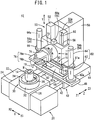
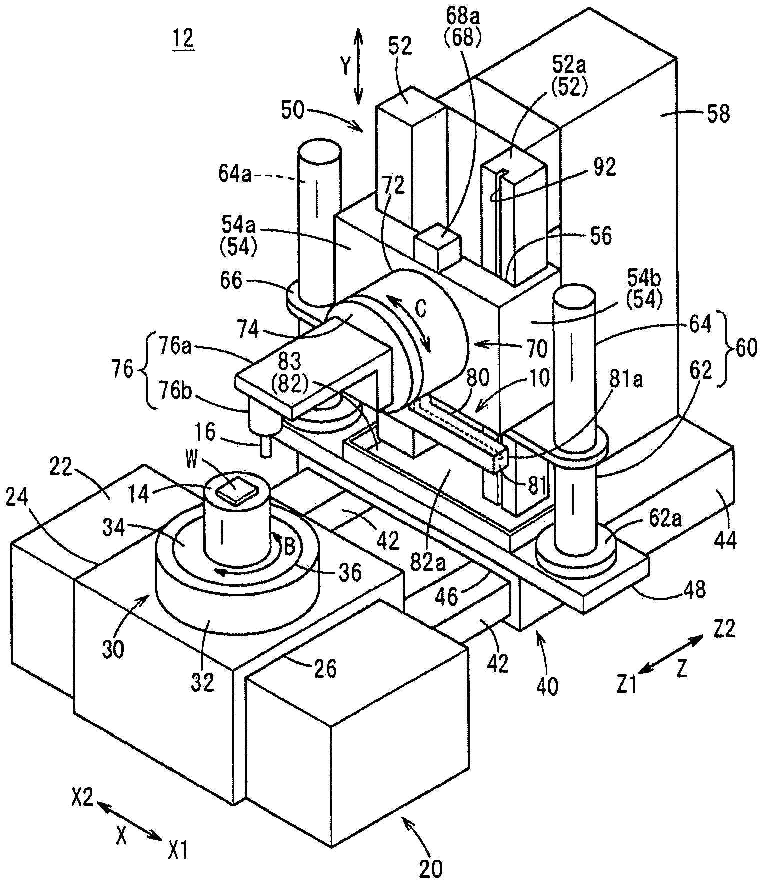
1 ist eine perspektivische Ansicht, die schematisch eine Werkzeugmaschine mit einer Flüssigkeits-Ablasseinrichtung gemäß einer Ausführungsform der vorliegenden Erfindung zeigt; 1 12 is a perspective view schematically showing a machine tool with a liquid drain device according to an embodiment of the present invention;
-
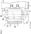
2 ist eine Seitenansicht, die eine Y-Achsen-Vorschubeinrichtung und eine C-Achsen-Dreheinrichtung einer mit einer Flüssigkeits-Ablasseinrichtung der vorliegenden Erfindung ausgerüsteten Werkzeugmaschine zeigt; 2nd Fig. 12 is a side view showing a Y-axis feeder and a C-axis rotator of a machine tool equipped with a liquid discharge device of the present invention;
-
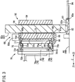
3 ist eine Seiten-Querschnittsansicht der Y-Achsen-Vorschubeinrichtung und der C-Achsen-Dreheinrichtung von 2; 3rd FIG. 14 is a side cross-sectional view of the Y-axis feeder and the C-axis rotator of FIG 2nd ;
-
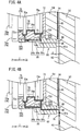
4A ist eine teilweise vergrößerte Schnittansicht, die die Flüssigkeits-Ablasseinrichtung von 3 zeigt; 4A FIG. 12 is a partially enlarged sectional view showing the liquid discharge device of FIG 3rd shows;
-
4B ist eine teilweise vergrößerte Schnittansicht, die einen Arbeitsablauf zeigt, bei dem eine Flüssigkeits-Ablasseinrichtung Öl abführt; und 4B Fig. 12 is a partially enlarged sectional view showing an operation in which a liquid drain device drains oil; and
-
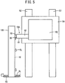
5 ist eine erläuternde Ansicht, die schematisch eine Flüssigkeits-Ablasseinrichtung gemäß einem Modifikationsbeispiel zeigt. 5 11 is an explanatory view schematically showing a liquid discharge device according to a modification example.
BESCHREIBUNG DER BEVORZUGTEN AUSFÜHRUNGSFORMENDESCRIPTION OF THE PREFERRED EMBODIMENTS
Eine Flüssigkeits-Ablasseinrichtung und eine Werkzeugmaschine mit der Flüssigkeits-Ablasseinrichtung gemäß der vorliegenden Erfindung werden durch Beschreiben einer bevorzugten Ausführungsform mit Bezug auf die beigefügten Zeichnungen ausführlich dargelegt.A liquid drain device and a machine tool having the liquid drain device according to the present invention are detailed by describing a preferred embodiment with reference to the accompanying drawings.
Wie in 1 gezeigt ist eine Flüssigkeits-Ablasseinrichtung 10 gemäß einer Ausführungsform der vorliegenden Erfindung als ein an einem hydrostatischen Drucklager einer Werkzeugmaschine 12 vorgesehenes Bauteil ausgestaltet, um als Fluid verwendetes Öl (Flüssigkeit: Schmiermittel) abzulassen. Insbesondere ist die Flüssigkeits-Ablasseinrichtung 10 gemäß der vorliegenden Ausführungsform auf einem beweglichen Teil (einem später beschriebenen Y-Achsenschlitten 54) vorgesehen, das sich in der vertikalen Richtung bewegt, und unterbindet das Zerstreuen des Öls durch Verhindern, dass das Öl von dem beweglichen Teil frei abfällt. Zusätzlich ist die Flüssigkeits-Ablasseinrichtung 10 so angebaut, dass sie die Bewegungssteuerung des beweglichen Teils nicht beeinträchtigt, wodurch es möglich ist, das Verhalten des beweglichen Teils während dessen Bewegung zu stabilisieren.As in 1 a liquid drain device is shown 10th according to an embodiment of the present invention as a on a hydrostatic pressure bearing of a machine tool 12 provided component designed to drain oil used as a fluid (liquid: lubricant). In particular, the liquid drain device 10th according to the present embodiment on a movable part (a Y-axis slide described later 54 ) provided which moves in the vertical direction, and prevents the oil from scattering by preventing the oil from falling freely from the moving part. In addition, the liquid drain device 10th mounted so that it does not interfere with the movement control of the moving part, whereby it is possible to stabilize the behavior of the moving part during its movement.
Nachfolgend wird zum leichteren Verständnis der Flüssigkeits-Ablasseinrichtung 10 gemäß der vorliegenden Erfindung zuerst die mit der Flüssigkeits-Ablasseinrichtung 10 ausgerüstete Werkzeugmaschine 10 beschrieben.The following is for easier understanding of the liquid drain device 10th According to the present invention, the one with the liquid discharge device is first 10th equipped machine tool 10th described.
Um ein Werkstück W zu bearbeiten, ist die Werkzeugmaschine 12 dazu ausgestaltet, eine 5-achsige Bearbeitung unter der Steuerung einer nicht dargestellten numerischen Steuerung auszuführen. Insbesondere ist die Werkzeugmaschine 12 dazu ausgestaltet, einen Tisch 14 mit einem darauf abgelegten Werkstück W in der X-Achsenrichtung hin und her zu bewegen und den Tisch 14 um eine B-Achse zu drehen. Des Weiteren ist die Werkzeugmaschine 12 dazu ausgestaltet, ein Werkzeug 16 zum Bearbeiten des Werkstücks W in der Z-Achsenrichtung (der Richtung zum und weg vom Tisch 14) und der Y-Achsenrichtung (vertikalen Richtung) hin und her zu bewegen und ein Schwenken des Werkzeugs 16 um eine C-Achse (Positionieren der Stellung des Werkzeugs 16) zu ermöglichen.To a workpiece W to machine is the machine tool 12 designed to carry out 5-axis machining under the control of a numerical control, not shown. In particular, the machine tool 12 designed to be a table 14 with a workpiece placed on it W to move back and forth in the x-axis direction and the table 14 to rotate a B axis. Furthermore, the machine tool 12 designed to be a tool 16 for machining the workpiece W in the Z-axis direction (the direction towards and away from the table 14 ) and the Y-axis direction (vertical direction) to reciprocate and pivot the tool 16 around a C axis (positioning the position of the tool 16 ) to enable.
Das heißt, zusätzlich zu den drei Vorschubachsen weist die Werkzeugmaschine 12 gemäß der vorliegenden Ausführungsform eine Drehachse in dem Tisch 14 und eine Drehachse der Spindel auf. Hierbei sollte die Werkzeugmaschine 12, an der die Flüssigkeits-Ablasseinrichtung 10 eingesetzt wird, nicht besonders durch die Anzahl von Achsen eingeschränkt werden. Weiterhin sollte der eingebaute Zustand der Drehachsen ebenfalls nicht eingeschränkt werden. Beispielsweise kann die Flüssigkeits-Ablasseinrichtung 10 an einer Maschine mit zwei Drehachsen auf der Seite des Tisches 14 oder einer Maschine mit zwei Drehachsen auf der Seite des Werkzeugs 16 eingesetzt werden.That means, in addition to the three feed axes, the machine tool has 12 according to the present embodiment, an axis of rotation in the table 14 and an axis of rotation of the spindle. Here the machine tool should 12 on which the liquid drain device 10th is not particularly limited by the number of axes. Furthermore, the installed condition of the rotary axes should not be restricted either. For example, the liquid drain device 10th on a machine with two axes of rotation on the side of the table 14 or a machine with two axes of rotation on the side of the tool 16 be used.
Die X-Achsen-Vorschubeinrichtung 20 der Werkzeugmaschine 12 besteht aus einem X-Achsen-Führungselement 22, einem X-Achsenschlitten 24, der der sich auf dem X-Achsen-Führungselement 22 hin und her bewegen kann, und einem hydrostatischen Drucklager 26 für die Vorschubachse, das zwischen dem X-Achsen-Führungselement 22 und dem X-Achsenschlitten 24 vorgesehen ist. Das hydrostatische Vorschubachsen-Drucklager 26 wird von einer nicht dargestellten Ölversorgungseinrichtung mit Öl eines vorbestimmten Öldrucks versorgt, um dadurch einen Ölfilm zwischen dem X-Achsen-Führungselement 22 und dem X-Achsenschlitten 24 zu bilden. Dadurch werden Schwingungen, die beim Bewegen des X-Achsenschlittens 24 erzeugt werden, gedämpft, sodass der X-Achsenschlitten 24 leichtgängig gleiten kann.The X-axis feed device 20th the machine tool 12 consists of an X-axis guide element 22 , an X-axis slide 24th which is on the X-axis guide element 22 can move back and forth, and a hydrostatic thrust bearing 26 for the feed axis, that between the X-axis guide element 22 and the X-axis slide 24th is provided. The hydrostatic feed axis thrust bearing 26 is supplied with oil of a predetermined oil pressure by an oil supply device, not shown, thereby forming an oil film between the X-axis guide member 22 and the X-axis slide 24th to build. This eliminates vibrations when moving the X-axis slide 24th generated, steamed, so the X axis slide 24th can slide smoothly.
Eine Dreheinrichtung 30 für die B-Achse der Werkzeugmaschine 12 besteht aus einem auf der Oberseite des X-Achsenschlittens 24 befestigten Stator 32 und einem im Innern des Stators 32 Rotors 34, der so angeordnet ist, dass er relativ zu dem Stator 32 drehbar ist, und umfasst ferner ein hydrostatisches Drucklager 36 zwischen dem Stator 32 und dem Rotor 34 für die Drehwelle. Dieses hydrostatische Drucklager 36 für die Drehwelle kann eine Einrichtung einsetzen, in der Luft als ein Fluid zwischen den Stator 32 und den Rotor 34 zugeführt wird, um einen Luftfilm zu bilden. Alternativ kann dieselbe Einrichtung (zum Zuführen von Öl als ein Fluid) wie die, die in der später beschriebenen C-Achsen-Dreheinrichtung 70 vorgesehen ist, übernommen werden. Der Tisch 14 zum Befestigen und Halten des Werkstücks W ist an der Oberseite des Rotors 34 angeordnet, sodass das Werkstück W auf der Oberseite des Tisches 14 positioniert und befestigt ist.A rotating device 30th for the B axis of the machine tool 12 consists of one on the top of the X-axis slide 24th attached stator 32 and one inside the stator 32 Rotors 34 which is arranged so that it is relative to the stator 32 is rotatable, and further comprises a hydrostatic pressure bearing 36 between the stator 32 and the rotor 34 for the rotating shaft. This hydrostatic thrust bearing 36 for the rotating shaft can use a device in the air as a fluid between the stator 32 and the rotor 34 is supplied to form an air film. Alternatively, the same device (for supplying oil as a fluid) as that in the C-axis rotating device described later can be used 70 is intended to be taken over. The table 14 for fastening and holding the workpiece W is at the top of the rotor 34 arranged so that the workpiece W on the top of the table 14 positioned and attached.
Die Z-Achsen-Vorschubeinrichtung 40 der Werkzeugmaschine 12 besteht aus einem Paar von Z-Achsen-Führungselementen 42 und einem Z-Achsenschlitten 44, der auf dem Paar von Z-Achsen-Führungselementen 42 hin und her fahren kann. Zwischen jedem der Z-Achsen-Führungselemente 42 und dem Z-Achsenschlitten 44 ist ein hydrostatisches Vorschubachsen-Drucklager 46 der vorgesehen, das dieselbe Struktur aufweist, wie die der X-Achsen-Vorschubeinrichtung 20. Eine Y-Achsen-Vorschubeinrichtung 50 ist auf der Oberseite des Z-Achsenschlittens 44 vorgesehen und eine Ölwanne 82, die einen Teil der Flüssigkeits-Ablasseinrichtung 10 darstellt, ist ebenfalls darauf vorgesehen.The Z-axis feed device 40 the machine tool 12 consists of a pair of Z-axis guide elements 42 and a Z-axis slide 44 on the pair of Z-axis guide elements 42 can drive back and forth. Between each of the Z-axis guide elements 42 and the Z-axis slide 44 is a hydrostatic feed axis thrust bearing 46 provided that has the same structure as that of the X-axis feed device 20th . A Y-axis feed device 50 is on the top of the Z-axis slide 44 provided and an oil pan 82 that are part of the liquid drain device 10th represents is also provided on it.
Die Y-Achsen-Vorschubeinrichtung 50 umfasst ein Paar von Y-Achsen-Führungselementen 52 und einen Y-Achsenschlitten 54 (bewegliches Teil), der entlang des Paars von Y-Achsen-Führungselementen 52 hin und her fahren kann. Zwischen jedem der Y-Achsen-Führungselemente 52 und dem Y-Achsenschlitten 54 ist ein hydrostatisches Vorschubachsen-Drucklager 56 vorgesehen, das eine ähnliche Struktur wie die der hydrostatischen Vorschubachsen-Drucklager 26 und 46 des X-Achsen- und des Z-Achsen-Vorschubmechanismus 20 und 40 aufweist. Des Weiteren umfasst die Y-Achsen-Vorschubeinrichtung 50 einen Stützkörper 58, der aufrecht auf der Oberseite des Z-Achsenschlittens 44 befestigt ist, und eine mechanische Luftausgleichseinheit 60 zum Unterstützen einer Aufwärts-/Abwärtsbewegung des Y-Achsenschlittens 54.The Y-axis feed device 50 includes a pair of Y-axis guide members 52 and a Y-axis slide 54 (moving part) running along the pair of Y-axis guide members 52 can drive back and forth. Between each of the Y-axis guides 52 and the Y-axis slide 54 is a hydrostatic feed axis thrust bearing 56 provided a structure similar to that of the hydrostatic feed axis thrust bearing 26 and 46 of the X-axis and Z-axis feed mechanisms 20th and 40 having. The Y-axis feed device also includes 50 a support body 58 that is upright on the top of the Z axis slide 44 is attached, and a mechanical air balancing unit 60 to support an up / down movement of the Y-axis slide 54 .
Das Paar von Y-Achsen-Führungselementen 52 erstreckt sich parallel zu der Bewegungsrichtung (vorbestimmter Pfad) des Y-Achsenschlittens und führt die Bewegung des Y-Achsenschlittens 54. Die Y-Achsen-Führungselemente 52 weisen jeweils eine rechtwinklige rohrförmige Form einer vorbestimmten Länge auf und sind so installiert, dass sie sich vertikal an einer voneinander beabstandeten Position erstrecken. Die Y-Achsen-Führungselemente 52 sind jeweils an einer Bodenfläche 82a befestigt und bilden einen Speicherraum 83 der Ölwanne 82. Von den vier Seiten der Y-Achsen-Führungselemente 52 bilden die Seitenflächen, mit Ausnahme einer Seitenfläche, die einem anderen Y-Achsen-Führungselement gegenüberliegt, Gleitflächen (eine der Lagerflächen des hydrostatischen Vorschubachsen-Drucklagers 56), auf denen der Y-Achsenschlitten 54 gleitet. Das dem hydrostatischen Vorschubachsen-Drucklager 56 zugeführte Öl haftet an diesen Gleitflächen und fließt nach unten.The pair of Y-axis guide elements 52 extends parallel to the direction of movement (predetermined path) of the Y-axis slide and guides the movement of the Y-axis slide 54 . The Y-axis guide elements 52 each have a rectangular tubular shape of a predetermined length and are installed so as to extend vertically at a spaced apart position. The Y-axis guide elements 52 are each on a floor surface 82a attached and form a storage space 83 the oil pan 82 . From the four sides of the Y-axis guide elements 52 the side surfaces, with the exception of a side surface which is opposite to another Y-axis guide element, form sliding surfaces (one of the bearing surfaces of the hydrostatic feed axis thrust bearing 56 ) on which the Y-axis slide 54 slides. The hydrostatic feed axis thrust bearing 56 supplied oil adheres to these sliding surfaces and flows downwards.
Des Weiteren ist das Paar von Y-Achsen-Führungselementen 52 an dem auf der Z2-Seite in 1 (siehe auch 2) befindlichen Stützkörper 58 befestigt, wodurch deren vertikale Stellung beibehalten wird. Obwohl der in 1 gezeigte Stützkörper 58 eine rechtwinklige parallelflache Blockform aufweist, kann der Stützkörper, um das auf den Z-Achsenschlitten 44 aufgelegte Gewicht zu reduzieren, in einer Rahmenstruktur mit einem Hohlraum ausgebildet werden.Furthermore, the pair of Y-axis guide elements 52 on the on the Z2 side in 1 (see also 2nd ) located support body 58 attached, thereby maintaining their vertical position. Although the in 1 support body shown 58 has a rectangular parallelepipedal block shape, the support body can be on the Z-axis slide 44 to reduce applied weight, be formed in a frame structure with a cavity.
Eines (das rechte in 1) der paarweisen Y-Achsen-Führungselemente 52 ist ein festes Element, das Teil der Flüssigkeits-Ablasseinrichtung 10 ist. Nachfolgend wird dieses Y-Achsen-Führungselement 52 auch als ein Y-Achsen-Ablassführungselement 52a bezeichnet. Die spezifischen Funktionen des Y-Achsen-Ablassführungselements 52a werden später beschrieben.One (the right one in 1 ) of the paired Y-axis guide elements 52 is a solid element that forms part of the liquid drain device 10th is. Below is this Y axis guide element 52 also as a Y-axis drain guide 52a designated. The specific functions of the Y-axis drain guide 52a will be described later.
Der Y-Achsenschlitten 54 besteht aus einem Befestigungswandabschnitt 54, an dem die C-Achsen-Dreheinrichtung 70 befestigt ist, und einem Paar von Führungswandabschnitten 54b, die auf beiden Seiten des Befestigungswandabschnitts 54a angeordnet sind. Der Y-Achsenschlitten 54 ist aus einem einzigen Stück durch einstückiges Formen ausgebildet. Der Befestigungswandabschnitt 54a weist eine flache Oberfläche auf und ist dick genug, um eine Steifigkeit zum Halten der C-Achsen-Dreheinrichtung 70 bereitzustellen. Die paarweisen Führungswandabschnitte 54b decken jeweilige Y-Achsen-Führungselemente 52 hakenartig ab, um den Y-Achsenschlitten 54 in der vertikalen Richtung zu verschieben, während ein Spiel oder Taumeln in der X-Richtung und der Z-Richtung unterbunden wird. Das heißt, die durch den Befestigungswandabschnitt 54a und das Paar von Führungswandabschnitten 54b gebildete Innenfläche definiert die andere Lagerfläche des hydrostatischen Vorschubachsen-Drucklagers 56, die der Gleitfläche eines jeden Y-Achsen-Führungselements 52 gegenüberliegt.The Y-axis slide 54 consists of a mounting wall section 54 on which the C-axis rotating device 70 is attached, and a pair of guide wall portions 54b that are on both sides of the mounting wall section 54a are arranged. The Y-axis slide 54 is formed from a single piece by one-piece molding. The mounting wall section 54a has a flat surface and is thick enough to provide rigidity to hold the C-axis rotator 70 to provide. The paired guide wall sections 54b cover respective Y-axis guide elements 52 hook-like around the Y-axis slide 54 to shift in the vertical direction while preventing play or wobble in the X and Z directions. That is, through the mounting wall section 54a and the pair of guide wall sections 54b The inner surface formed defines the other bearing surface of the hydrostatic feed axis thrust bearing 56 that of the sliding surface of each Y-axis guide member 52 opposite.
Des Weiteren wird der Y-Achsenschlitten 54 durch die an einer Verlängerungsplatte 48 auf dem Z-Achsenschlitten befestigte mechanische Luftausgleichseinheit 60 beim vertikalen Verschieben unterstützt. Die mechanische Luftausgleichseinheit 60 umfasst ein Paar von festen Wellen 62, die auf der Oberseite an beiden Seiten der Verlängerungsplatte 48 vorgesehen sind, und ein Paar von beweglichen Zylindern 64, die außen an den jeweiligen festen Wellen 63 so befestigt sind, dass sie sich relativ dazu bewegen können. Furthermore, the Y-axis slide 54 through on an extension plate 48 mechanical air compensation unit attached to the Z-axis slide 60 supported when moving vertically. The mechanical air balance unit 60 includes a pair of fixed shafts 62 that are on the top on both sides of the extension plate 48 are provided, and a pair of movable cylinders 64 that are outside on the respective fixed shafts 63 are attached so that they can move relative to it.
Die paarweisen festen Wellen 62 weisen jeweils eine zylindrische Form auf, die sich mit einer vorbestimmten Länge von einer an einem unteren Ende derselben vorgesehenen Befestigungsplatte 62a, die an der Verlängerungsplatte 48 befestigt ist, nach oben erstreckt. Die paarweisen beweglichen Zylinder 64 weisen jeweils einen inneren Hohlraum 64a mit einem Durchmesser, der etwas größer als der Außendurchmesser der festen Welle 62 ist, auf, und die festen Wellen 62 werden mit den beweglichen Zylindern 64 abgedeckt. Ein Brückenrahmen 66 erstreckt sich von dem unteren Ende eines jeden der paarweisen beweglichen Zylinder 64 in Richtung auf jede Seite des Y-Achsenschlittens 54 und ist mit dem Y-Achsenschlitten 54 verbunden.The paired solid waves 62 each have a cylindrical shape extending a predetermined length from a mounting plate provided at a lower end thereof 62a attached to the extension plate 48 attached, extends upwards. The pair of movable cylinders 64 each have an inner cavity 64a with a diameter slightly larger than the outer diameter of the fixed shaft 62 is on and the fixed waves 62 are with the movable cylinders 64 covered. A bridge frame 66 extends from the lower end of each of the paired movable cylinders 64 towards each side of the Y-axis slide 54 and is with the Y-axis slide 54 connected.
In der so ausgestalteten mechanischen Luftausgleichseinheit 60 wird den inneren Hohlräumen 64a des Paars von beweglichen Zylindern 64 zu angemessenen Zeiten Arbeitsluft durch eine nicht dargestellten Arbeitsluft-Versorgungseinrichtung zugeführt oder daraus abgeführt. Dadurch werden die beweglichen Zylinder 64 relativ zu den festen Wellen 62 bewegt. Das heißt, wenn der Y-Achsenschlitten 54 in der vertikalen Richtung bewegt wird, steuert die mechanische Luftausgleichseinheit 60 den Antrieb der Y-Achsen-Vorschubeinrichtung 50, und als Ergebnis der Steuerung des Antreiben wird die Last des Y-Achsenschlittens 54 (mit der C-Achsen-Dreheinrichtung 70, der Spindeleinrichtung 76, dem Werkzeug 16, usw.) verteilt und durch die mechanische Luftausgleichseinheit 60 aufgenommen. Als ein Ergebnis kann sich der Y-Achsenschlitten leichtgängig auf und ab bewegen.In the mechanical air balancing unit designed in this way 60 becomes the internal cavities 64a of the pair of movable cylinders 64 Working air is supplied or removed from the working air supply device, not shown, at appropriate times. This will make the moving cylinders 64 relative to the fixed waves 62 emotional. That is, if the Y-axis slide 54 is moved in the vertical direction, controls the mechanical air balancing unit 60 the drive of the Y-axis feed device 50 , and as a result of the driving control, the load of the Y-axis carriage 54 (with the C-axis rotating device 70 , the spindle device 76 , the tool 16 , etc.) distributed and by the mechanical air balancing unit 60 added. As a result, the Y-axis slide can move up and down smoothly.
Des Weiteren umfasst der Y-Achsenschlitten 54 eine Ölversorgungseinrichtung 68 an einem oberen Teil desselben, um der Y-Achsen-Vorschubeinrichtung 50 und der C-Achsen- Dreheinrichtung 70 Öl zuzuführen. Die Ölversorgungseinrichtung 68 umfasst einen Öltank 68a zum Speichern von Öl und einen im Innern des Y-Achsenschlittens 54 vorgesehenen Vorschubachsen-Strömungsdurchlass 68b, um dem hydrostatischen Vorschubachsen-Drucklager 56 Öl zuzuführen. Eine (nicht gezeigte) Pumpe ist an einem Ölversorgungsanschluss des Öltanks 68a vorgesehen und wird angetrieben, um das Öl aus dem Öltank 68a auszulassen. Es wird angemerkt, dass die Ölversorgungseinrichtung 68 an einer anderen Position in der Werkzeugmaschine 12 angeordnet werden kann und die Einrichtung 68 beispielsweise an dem Stützkörper 58 oder dergleichen angebracht werden kann, um über ein nicht dargestelltes Rohr Öl an den Strömungsdurchlass des Y-Achsenschlittens 54 zu liefern.The Y-axis slide also includes 54 an oil supply facility 68 on an upper part thereof, around the Y-axis feeder 50 and the C-axis rotator 70 To supply oil. The oil supply facility 68 includes an oil tank 68a for storing oil and one inside the Y-axis slide 54 provided feed axis flow passage 68b to the hydrostatic feed axis thrust bearing 56 To supply oil. A pump (not shown) is on an oil supply port of the oil tank 68a provided and driven to remove the oil from the oil tank 68a omit. It is noted that the oil supply facility 68 at a different position in the machine tool 12 can be arranged and the facility 68 for example on the support body 58 or the like can be attached to oil through a pipe, not shown, to the flow passage of the Y-axis slide 54 to deliver.
Die C-Achsen-Dreheinrichtung 70 besteht aus einem an dem Y-Achsenschlitten 54 befestigten Stator 72 und einem relativ zu dem Stator 72 drehbaren Rotor 74. Der Rotor 74 ist teilweise im Innern des Stators 72 untergebracht und ist an einer von dem Y-Achsenschlitten 54 entfernten Seite (Z1-Seite in 1) freigelegt. Eine Spindeleinrichtung 76 zum Antreiben des Werkzeugs 16, um das Werkstück W zu bearbeiten, ist an einer Vorderseite (der Z1-Seite in 1) des Rotors 74 angebracht.The C-axis rotating device 70 consists of one on the Y-axis slide 54 attached stator 72 and one relative to the stator 72 rotatable rotor 74 . The rotor 74 is partly inside the stator 72 housed and is on one of the Y-axis slide 54 distant side (Z1 side in 1 ) exposed. A spindle device 76 for driving the tool 16 to the workpiece W is to be edited on a front side (the Z1 side in 1 ) of the rotor 74 appropriate.
Die Spindeleinrichtung 76 ist nicht besonders eingeschränkt, sondern kann ein Sägen, Entgraten, Schneiden und andere Bearbeitungen ausführen. Die Spindeleinrichtung 76 umfasst zum Beispiel einen in Seitenansicht L-förmigen Träger 76a und eine Spindel 76b, die ein Werkzeug 16 auf einer verlängerten Seite des Trägers 76a trägt und das Werkstück 16 um eine Achse dreht. Das heißt, das bewegliche Teil gemäß der vorliegenden Ausführungsform ist eine Baugruppe, die die C-Achsen-Dreheinrichtung 70, die Spindeleinrichtung 76 und das Werkzeug 16 umfasst.The spindle device 76 is not particularly limited, but can perform sawing, deburring, cutting and other processing. The spindle device 76 includes, for example, a L-shaped beam in side view 76a and a spindle 76b that is a tool 16 on an extended side of the carrier 76a carries and the workpiece 16 rotates around an axis. That is, the movable member according to the present embodiment is an assembly that is the C-axis rotator 70 , the spindle device 76 and the tool 16 includes.
Wie in den 2 und 3 gezeigt ist der Stator 72 als Teil der C-Achsen-Dreheinrichtung in einer im Wesentlichen zylindrischen Form ausgebildet und weist ein Gehäuseraum 73 zum Aufnehmen des Rotors 74 auf. An einer Innenumfangsfläche, die den Gehäuseraum 73 des Stators 72 definiert, ist ein ringförmig vorstehender erster innerer Vorsprung 72a in der Umfangsrichtung ausgebildet. Des Weiteren ist ein zweiter innerer Vorsprung 72b, der radial nach innen vorsteht, am Innenumfang im vorderen Teil des Stators 72 ausgebildet, um Öl am Auslaufen zur Vorderseite (der Z1-Seite in 1) des Rotors 74 zu hindern.As in the 2nd and 3rd the stator is shown 72 formed as part of the C-axis rotating device in a substantially cylindrical shape and has a housing space 73 to accommodate the rotor 74 on. On an inner peripheral surface that defines the housing space 73 of the stator 72 is defined, a ring-like protruding first inner projection 72a formed in the circumferential direction. Furthermore, there is a second inner lead 72b , which protrudes radially inwards, on the inner circumference in the front part of the stator 72 Trained to drain oil to the front (the Z1 side in 1 ) of the rotor 74 to prevent.
Das heißt, an der Innenumfangsfläche des Stators 72 ist eine erste Nut 72d (ausgenommener Abschnitt) zwischen einer an dem Y-Achsenschlitten 54 zu befestigenden Bodenwand 72c und dem ersten inneren Vorsprung 72a ausgebildet, und eine zweite Nut 72e (ausgenommener Abschnitt) ist zwischen dem ersten inneren Vorsprung 72a und dem zweiten inneren Vorsprung 72b ausgebildet.That is, on the inner peripheral surface of the stator 72 is a first groove 72d (Excepted section) between one on the Y-axis slide 54 floor wall to be fastened 72c and the first inner projection 72a trained, and a second groove 72e (recessed portion) is between the first inner protrusion 72a and the second inner protrusion 72b educated.
Andererseits hat der Rotor 74 einen zylindrischen Abschnitt 75, der in dem Gehäuseraum 73 des Stators 72 gelagert ist, und einen Scheibenabschnitt 74a, der mit der Vorderseite des zylindrischen Abschnitt 75 verbunden ist und von dem Stator 72 freigelegt ist. Zwei ringförmige Vorsprünge 75a sind an der Außenumfangsfläche des zylindrischen Abschnitts 75 ausgebildet. Die zwei ringförmigen Vorsprünge 75a sind in der ersten und zweiten Nut 72d und 72e des Stators 72 untergebracht, sodass der Rotor 74 nicht vom Stator 72 gelöst werden kann. Der Rotor 74 wird um die axiale Mitte (C-Achse) durch einen in einer in der Mitte ausgebildeten Bohrung eingebrachten Motor (zum Beispiel eine nicht dargestellte, aus Spulen und Magnete bestehende Einrichtung) gedreht.On the other hand, the rotor 74 a cylindrical section 75 who in the housing room 73 of the stator 72 is stored, and a disc section 74a that with the front of the cylindrical section 75 is connected and from the stator 72 is exposed. Two ring-shaped projections 75a are on the outer peripheral surface of the cylindrical portion 75 educated. The two annular protrusions 75a are in the first and second groove 72d and 72e of the stator 72 housed so the rotor 74 not from the stator 72 can be solved. The rotor 74 is rotated around the axial center (C-axis) by a motor (for example a device, not shown, consisting of coils and magnets) which is introduced into a bore formed in the center.
In der C-Achsen-Dreheinrichtung 70 bildet ein Freiraum C, der zwischen dem ersten inneren Vorsprung 72a des Stators 72 und den zwei ringförmigen Vorsprüngen 75a ausgebildet ist und der Fläche 75b des Rotors 74 gegenüberliegt, ein hydrostatisches Drehwellen-Drucklager 78. Des Weiteren nutzt die Werkzeugmaschine 12die obengenannten Ölversorgungseinrichtung 68, um Öl an das hydrostatische Drehwellen-Drucklager 78 zu liefern.In the C-axis rotating device 70 forms a free space C between the first inner projection 72a of the stator 72 and the two annular protrusions 75a is formed and the area 75b of the rotor 74 opposite, a hydrostatic rotary shaft thrust bearing 78 . Furthermore, the machine tool 12 uses the above-mentioned oil supply device 68 to supply oil to the hydrostatic rotary shaft thrust bearing 78 to deliver.
Insbesondere ist ein Drehwellen-Strömungsdurchlass 77 im Innern des Y-Achsenschlittens 54 und im Innern des Stators 72 ausgebildet, um mit dem Öltank 68a der oben beschriebenen Ölversorgungseinrichtung 68 zu kommunizieren. Beispielsweise öffnet sich ein Ende des Drehwellen-Strömungsdurchlass 77 an der vorstehenden Fläche des ersten inneren Vorsprungs 72a des Stators 72 und kommuniziert mit dem durch die gegenüberliegende Fläche 75b gebildeten Freiraum C. Als ein Ergebnis wird Öl über den Drehwellen-Strömungsdurchlass 77 von dem Öltank 68a an das hydrostatische Drehwellen-Drucklager 78 geliefert. Hierbei kann die Einrichtung zum Zuführen von Öl an das hydrostatische Drehwellen-Drucklager 78 getrennt von der Ölversorgungseinrichtung 68 zum Zuführen von Öl an das hydrostatische Vorschubachsen-Drucklager 56 vorgesehen werden.In particular, there is a rotary shaft flow passage 77 inside the Y-axis slide 54 and inside the stator 72 trained to use the oil tank 68a the oil supply device described above 68 to communicate. For example, one end of the rotary shaft flow passage opens 77 on the protruding surface of the first inner protrusion 72a of the stator 72 and communicates with that through the opposite surface 75b Free space C. As a result, oil flows through the rotary shaft flow passage 77 from the oil tank 68a to the hydrostatic rotary shaft thrust bearing 78 delivered. Here, the device for supplying oil to the hydrostatic rotary shaft thrust bearing 78 separate from the oil supply system 68 for supplying oil to the hydrostatic feed axis thrust bearing 56 be provided.
Öl wird an den Gehäuseraum 73 des Stators 72 über den Drehwellen-Strömungsdurchlass 77 geliefert, wodurch ein Ölfilm in dem Freiraum C des hydrostatischen Drehwellen-Drucklagers 78 gebildet wird und der Rotor 74 leichtgängig drehen kann. Um das Öl aus dem hydrostatischen Drehwellen-Drucklager 78 abzulassen, wird die Werkzeugmaschine 12 mit der Flüssigkeits-Ablasseinrichtung 10 versehen.Oil is going to the housing space 73 of the stator 72 via the rotary shaft flow passage 77 supplied, whereby an oil film in the clearance C of the hydrostatic rotary shaft thrust bearing 78 is formed and the rotor 74 can turn easily. To the oil from the hydrostatic rotary shaft thrust bearing 78 lowering the machine tool 12 with the liquid drain device 10th Mistake.
Die Flüssigkeits-Ablasseinrichtung 10 umfasst einen Teil der C-Achsen-Dreheinrichtung 70 (Stator 72), eine an einer Außenumfangsfläche des Stators 72 angebrachte Düse 80 (Ausstoßer), ein Y-Achsen-Ablassführungselement 52a und die Ölwanne 82.The liquid drain device 10th includes part of the C-axis rotator 70 (Stator 72 ), one on an outer peripheral surface of the stator 72 attached nozzle 80 (Pusher), a Y-axis drain guide 52a and the oil pan 82 .
Wie in 4A gezeigt weist die Flüssigkeits-Ablasseinrichtung 10 eine Mehrzahl von Ausströmlöchern 84 (Strömungsdurchlässe) unter dem Stator 72 auf, um dem Öl zu erlauben, aus dem Gehäuse zur Außenseite auszufließen. Ein erstes Ausströmloch 84a ist so ausgebildet, dass es von der ersten Nut 72d des Stators 72 vertikal nach unten zu der Außenumfangsfläche durchdringt. Ein zweites Ausströmloch 84b ist so ausgebildet, dass es von der zweiten Nut 72e des Stators 72 vertikal nach unten zu der Außenumfangsfläche durchdringt. Das heißt, das Öl des hydrostatischen Drehwellen-Drucklagers 78 bildet einen Ölfilm und fließt dann in die erste und zweite Nut 72d, 72d, die in einer niedrigeren Ebene liegen als der erste innere Vorsprung 72a. Aufgrund des ersten und zweiten Ausströmlochs 84a, 84b kann das Öl leicht aus dem Gehäuseraum 73 abgeführt werden. Es wird angemerkt, dass ein oder mehrere Ausströmlöcher 84 vorgesehen werden können.As in 4A shown has the liquid discharge device 10th a plurality of outflow holes 84 (Flow passages) under the stator 72 to allow the oil to flow out of the housing to the outside. A first outflow hole 84a is designed so that it is from the first groove 72d of the stator 72 penetrates vertically down to the outer peripheral surface. A second outflow hole 84b is designed so that it is from the second groove 72e of the stator 72 penetrates vertically down to the outer peripheral surface. That is, the oil from the hydrostatic rotary shaft thrust bearing 78 forms an oil film and then flows into the first and second grooves 72d , 72d that are at a lower level than the first inner protrusion 72a . Because of the first and second outflow hole 84a , 84b the oil can easily come out of the housing space 73 be dissipated. It is noted that one or more outflow holes 84 can be provided.
Andererseits wird die Düse 80 der Flüssigkeits-Ablasseinrichtung 10 in einer rechtwinkligen rohrförmigen Form vorgesehen. Die Düse 80 ist an einer unteren Position des Stators 72 so befestigt, dass sie die ersten und zweiten Ausströmlöcher 84a und 84b abdeckt. Des Weiteren erstreckt sich die Düse 80 von dem festen Abschnitt des Stators 72 in Richtung auf den Y-Achsenschlitten 54 (Z2-Seite), krümmt sich zur X1-Seite unterhalb des Y-Achsenschlittens 54, wie in 1 gezeigt, und erstreckt sich weiter zu der Y-Achsen-Ablassführungselementseite 52a (die X1-Seite in 1). Eine Seitenfläche auf der Z2-Seite eines verlängerten Endabschnitts 81 der Düse 80 (die nachfolgend als eine Düsen-Stirnseitenfläche 81a bezeichnet wird) liegt dem Y-Achsen-Ablassführungselement 52a gegenüber. In der vorliegenden Ausführungsform sind der Stator 72 und die Düse 80 getrennt ausgebildet, wobei jedoch diese Bauteile einstückig ausgebildet werden können.On the other hand, the nozzle 80 the liquid drain device 10th provided in a rectangular tubular shape. The nozzle 80 is at a lower position of the stator 72 attached so that they have the first and second outflow holes 84a and 84b covers. The nozzle also extends 80 from the fixed section of the stator 72 towards the Y-axis slide 54 (Z2 side), curves to the X1 side below the Y-axis slide 54 , as in 1 and extends to the Y-axis exhaust guide member side 52a (the X1 side in 1 ). A side surface on the Z2 side of an elongated end section 81 the nozzle 80 (hereinafter referred to as a nozzle face 81a ) is the Y-axis drain guide member 52a across from. In the present embodiment, the stator 72 and the nozzle 80 formed separately, but these components can be formed in one piece.
Wie in den 1 und 4A gezeigt ist ein Düsen-Strömungsdurchlass 86 (Strömungsdurchlass) für durchfließendes Öl im Innern der Düse 80 von dem festen Abschnitt des Stators 72 zu dem verlängerten Endabschnitt 81 ausgebildet. Der Düsen-Strömungsdurchlass 86 besteht aus einem ersten Strömungsdurchlass 86a, der mit dem ersten Ausströmloch 84a kommuniziert, einem zweiten Strömungsdurchlass 86b, der mit dem zweiten Ausströmloch 84b kommuniziert, und einem dritten Strömungsdurchlass 86c, der mit einem an der Düsen-Stirnseitenfläche 81a vorgesehenen Ausstoßanschluss 88 kommuniziert. Die ersten bis dritten Strömungsdurchlässe 86a bis 86c treffen in der Düse 80 zusammen. Das aus dem ersten und zweiten Ausströmloch 84a, 84b ausfließende Öl wird durch den ersten und zweiten Strömungsdurchlass 86a, 86b aufgenommen und fließt in den dritten Strömungsdurchlass 86c. Dann lässt der dritte Strömungsdurchlass 86c das Öl entlang der verlängerten Form der Düse 80 fließen, und führt das Öl aus dem Ausstoßanschluss 88 (Auslass) an der Düsen-Stirnseitenfläche 81a ab. Es sollte angemerkt werden, dass der Düsen-Strömungsdurchlass 86 nach unten in Richtung auf den Ausstoßanschluss 88 geneigt sein kann.As in the 1 and 4A a nozzle flow passage is shown 86 (Flow passage) for oil flowing through inside the nozzle 80 from the fixed section of the stator 72 to the elongated end section 81 educated. The nozzle flow passage 86 consists of a first flow passage 86a that with the first outflow hole 84a communicates, a second flow passage 86b that with the second outflow hole 84b communicates, and a third flow passage 86c that with a on the nozzle face 81a provided outlet connection 88 communicates. The first to third flow passages 86a to 86c hit in the nozzle 80 together. That from the first and second outflow hole 84a , 84b outflowing oil passes through the first and second flow passages 86a , 86b recorded and flows into the third flow passage 86c . Then the third flow passage leaves 86c the oil along the elongated shape of the nozzle 80 flow, and leads the oil out of the discharge port 88 (Outlet) on the nozzle face 81a from. It should be noted that the Nozzle flow passage 86 down towards the exhaust port 88 can be inclined.
Hierbei ist ein Spalt 90 zwischen der Düsen-Stirnseitenfläche 81a (Ausstoßanschluss 88) der Düse 80 und einer Seitenfläche (einer Seitenfläche auf der Z1-Seite) des Y-Achsen-Ablassführungselements 52a, das der Düsen-Stirnseitenfläche 81a gegenüberliegt, vorgesehen. Der Abstand d des Spalts 90 kann und sollte auf einen solchen Abstand eingestellt werden, dass das aus dem Ausstoßanschluss 88 ausgestoßene Öl die Seitenfläche auf der Z1-Seite erreichen kann, zum Beispiel auf ungefähr 0,5 mm bis 3 mm. In der vorliegenden Ausführungsform ist der Abstand d auf 1 mm eingestellt. Dieser Spalt 90 erlaubt der Düse 80 sich einstückig vertikal mit dem Y-Achsenschlitten 54 zu bewegen, während sie außer Kontakt mit dem Y-Achsen-Ablassführungselement 52a bleibt. Des Weiteren kann das aus dem Ausstoßanschluss 88 abgeführte Öl zuverlässig auf das sich in der Nähe befindliche Y-Achsen-Ablassführungselement 52a gegossen werden.There is a gap here 90 between the nozzle face 81a (Exhaust port 88 ) the nozzle 80 and a side surface (a side surface on the Z1 side) of the Y-axis exhaust guide member 52a that of the nozzle face 81a opposite, provided. The distance d of the gap 90 can and should be set to such a distance that it comes out of the exhaust port 88 ejected oil can reach the side surface on the Z1 side, for example, about 0.5 mm to 3 mm. In the present embodiment, the distance d is set to 1 mm. That gap 90 allowed the nozzle 80 one piece vertically with the Y-axis slide 54 to move while out of contact with the Y-axis drain guide 52a remains. Furthermore, this can be done from the exhaust port 88 drained oil reliably on the nearby Y-axis drain guide 52a be poured.
Zusätzlich ist der Ausstoßanschluss 88 an einer Position vorgesehen, die einer Abflussnut 92 (Nut) des Y-Achsen-Ablassführungselement 52 gegenüberliegt. Die in dem Y-Achsen-Ablassführungselement 52a ausgebildete Abflussnut 92 erstreckt sich vertikal auf der Gleitfläche (der Seitenfläche auf der Z1-Seite in 1) des Y-Achsen-Führungselements 52, das der C-Achsen-Dreheinrichtung 70 gegenüberliegt, und bildet eine Pfad, um das Öl nach unten fließen zu lassen. Das aus dem Ausstoßanschluss 88 abgeführte Öl tritt ohne weiteres in die Abflussnut 92 ein, ohne dass die Gleitfläche des Y-Achsen-Ablassführungselement 52a berührt wird. Wenn Öl auf das Y-Achsen-Führungselement 52a gegossen wird, wird als Ergebnis das Öl am Zerstreuen in alle Richtungen gehindert.In addition, the exhaust port 88 provided at a position that a drain groove 92 (Groove) of the Y-axis drain guide 52 opposite. The in the Y-axis drain guide 52a trained drainage groove 92 extends vertically on the sliding surface (the side surface on the Z1 side in 1 ) of the Y-axis guide element 52 that of the C-axis rotating device 70 opposite, and forms a path to let the oil flow down. That from the exhaust port 88 drained oil easily enters the drain groove 92 without the sliding surface of the Y-axis drain guide 52a is touched. If oil on the Y-axis guide 52a as a result, the oil is prevented from scattering in all directions.
Da das aus der Düse 80 abgeführte Öl stetig auf dieselbe Stelle in der Abflussnut 92 gegossen wird, ist es möglich, mit Leichtigkeit eine Durchflussrate sicherzustellen, bei der das Öl leicht nach unten fließt. Hierbei kann die Abflussnut 92 relativ flach ausgebildet werden (beispielsweise mit einer Tiefe, die kürzer als der Abstand d ist). Ferner kann die Abflussnut 92 in jedem der paarweisen Y-Achsen-Führungselemente 52 vorgesehen werden. Weiterhin kann in dem Y-Achsen-Führungselement 52 das Öl entlang einer Gleitfläche fließen, ohne dass es eine Abflussnut 92 aufweist.Because that from the nozzle 80 drained oil steadily to the same place in the drain groove 92 is poured, it is possible to easily ensure a flow rate at which the oil flows down easily. Here, the drain groove 92 be formed relatively flat (for example with a depth that is shorter than the distance d). Furthermore, the drain groove 92 in each of the paired Y-axis guide elements 52 be provided. Furthermore, in the Y-axis guide element 52 the oil flow along a sliding surface without making a drain groove 92 having.
Wie in den 1 und 3 gezeigt, ist die Ölwanne 82 der Flüssigkeits-Ablasseinrichtung 10 unter dem Y-Achsen-Führungselement 52 vorgesehen. Die Ölwanne 82 ist in einer oben offenen Kastenform ausgebildet, die einen Speicherraum 83 aufweist, der Öl zwischenspeichern kann, das entlang der Abflussnut 92 nach unten geflossen ist. Die Ölwanne 82 hat einen Abführanschluss 83a, um das Öl in dem Speicherraum 83 nach außen abzuführen, und ein Rohr 94 einer (nicht gezeigten) Ölsammeleinrichtung ist mit dem Abführanschluss 83a verbunden. Eine Bodenfläche 82a der Ölwanne 82 ist bevorzugt nach unten in Richtung auf den Abführanschluss 83 geneigt, wodurch Öl zwangsweise zum Abführanschluss 83 angeströmt werden kann. Des Weiteren wird bevorzugt, dass die Ölsammeleinrichtung dazu ausgestaltet ist, das Öl zurückzugewinnen und das gesammelte Öl an die Ölversorgungseinrichtung 68 zurückzuführen.As in the 1 and 3rd shown is the oil pan 82 the liquid drain device 10th under the Y-axis guide 52 intended. The oil pan 82 is formed in an open box shape, which has a storage space 83 which can cache oil along the drain groove 92 flowed down. The oil pan 82 has a drain connection 83a to the oil in the storage room 83 lead away to the outside, and a pipe 94 an oil collector (not shown) is connected to the drain port 83a connected. A floor area 82a the oil pan 82 is preferably down towards the discharge connection 83 inclined, forcing oil to the drain port 83 can be flown to. Furthermore, it is preferred that the oil collecting device is configured to recover the oil and the collected oil to the oil supply device 68 attributed.
Die Flüssigkeits-Ablasseinrichtung 10 gemäß der vorliegenden Ausführungsform und die mit der Flüssigkeits-Ablasseinrichtung ausgerüstete Werkzeugmaschine 12 sind im Grunde wie oben beschrieben ausgestaltet. Nun werden nachfolgend die Arbeitsweise und die Wirkung beschrieben.The liquid drain device 10th according to the present embodiment and the machine tool equipped with the liquid discharge device 12 are basically designed as described above. The mode of operation and the effect are now described below.
Bei der Bearbeitung des Werkstücks W unter der Steuerung der Numerischen Steuerung bewegt die Werkzeugmaschine 12 den Y-Achsenschlitten 54 in der vertikalen Richtung und dreht den Rotor 74 der C-Achsen-Dreheinrichtung 70, um dadurch die Spindeleinrichtung 76 (Werkzeug 16) zu positionieren. Wenn der Y-Achsenschlitten 54 vertikal bewegt wird, wird über den Vorschubachsen-Strömungsdurchlass 68b des Y-Achsenschlittens 54 Öl OL von der Ölversorgungseinrichtung 68 an das hydrostatische Vorschub-Drucklager 56 geliefert. Der Abstand d des Spalts 90 zwischen der Düse 80 der Flüssigkeits-Ablasseinrichtung 10 und dem Y-Achsen-Ablassführungselement 52a wird konstant gehalten, um dadurch eine leichtgängige Bewegung des Y-Achsenschlittens 54 sicherzustellen.When machining the workpiece W The machine tool moves under the control of the numerical control 12 the Y-axis slide 54 in the vertical direction and rotates the rotor 74 the C-axis rotating device 70 to thereby remove the spindle device 76 (Tool 16 ) to position. If the Y-axis slide 54 is moved vertically, is via the feed axis flow passage 68b of the Y-axis slide 54 oil OIL from the oil supply facility 68 to the hydrostatic feed pressure bearing 56 delivered. The distance d of the gap 90 between the nozzle 80 the liquid drain device 10th and the Y-axis drain guide 52a is kept constant to ensure smooth movement of the Y-axis slide 54 ensure.
Wenn die C-Achsen-Dreheinrichtung 70 angetrieben wird, wird ferner durch die Ölversorgungseinrichtung 68 das Öl OL an das hydrostatische Drehwellen-Drucklager 79 geliefert. Das Öl OL wird aus dem Öltank 68a an den Gehäuseraums 73 über den Drehwellen-Strömungsdurchlass 77 geliefert, um einen Ölfilm in dem Freiraum C zwischen dem Stator 72 und dem Rotor 74 zu bilden.When the C-axis rotator 70 is also driven by the oil supply device 68 the oil OIL to the hydrostatic rotary shaft thrust bearing 79 delivered. The oil OIL becomes from the oil tank 68a on the housing room 73 via the rotary shaft flow passage 77 delivered to an oil film in the space C between the stator 72 and the rotor 74 to build.
Wie in 4A gezeigt sammelt sich daher das an das hydrostatische Drehwellen-Drucklager 78 in dem unteren Teil des Gehäuseraums 73 des Stators 72 an. Dieses Öl OL fließt in die erste und zweite Nut 72d, 72e und fließt aus dem ersten und zweiten Ausströmloch 84a, 84b, die als Teil der Flüssigkeits-Ablasseinrichtung 10 vorgesehen sind, am unteren Abschnitt des Stators 72 aus. Des Weiteren fließt das Öl OL nach unten durch das erste und das zweite Ausströmloch 84a, 84b und fließt dann in den Düsen-Strömungsdurchlass 86 der Düse 80.As in 4A shown therefore accumulates on the hydrostatic rotary shaft thrust bearing 78 in the lower part of the housing room 73 of the stator 72 at. That oil OIL flows into the first and second groove 72d , 72e and flows out of the first and second outflow holes 84a , 84b that are part of the liquid drain device 10th are provided on the lower section of the stator 72 out. The oil also flows OIL down through the first and second outflow holes 84a , 84b and then flows into the nozzle flow passage 86 the nozzle 80 .
Im Innern der Düse 80 fließt das Öl OL durch den ersten und zweiten Strömungsdurchlass 86a, 86b, kommt am dritten Strömungsdurchlass 86c zusammen und fließt weiter durch den dritten Strömungsdurchlass 86c zu dem verlängerten Endabschnitt 81 der Düse 80. Dann, wie in 4B gezeigt, wird das Öl, das den dritten Strömungsdurchgang 86c durchlaufen hat, aus dem Ausstoßanschluss 88 an der Düsen-Stirnseitenfläche 81 in Richtung auf das Y-Achsen-Abflussführungselement 52a abgeführt.Inside the nozzle 80 the oil flows OIL through the first and second flow passages 86a , 86b comes at the third flow passage 86c together and continues to flow through the third flow passage 86c to the elongated end section 81 the nozzle 80 . Then, like in 4B shown is the oil that makes the third flow passage 86c has passed out of the exhaust port 88 on the face of the nozzle 81 towards the Y-axis drain guide 52a dissipated.
Da, wie oben beschrieben, die Düsen-Stirnseitenfläche 81a und die Seitenfläche des Y-Achsen-Ablassführungselements 52 nur durch den kleinen Spalt 90 beabstandet sind, tropft das aus dem Ausstoßanschluss 88 ausgestoßene Öl OL nicht direkt aus der Düse 80, sondern wird auf (erreicht) die Seitenfläche des Y-Achsen-Führungselements 52 gegossen. Da des Weiteren der Ausstoßanschluss 88 dazu angeordnet ist, das Öl an die Abflussnut 92 des Y-Achsen-Führungselements 52 abzuführen, fließt das Öl OL entlang der Abflussnut 92 nach unten. Da weiterhin das in dem hydrostatischen Vorschubachsen-Drucklager 56 verwendete Öl auf der Oberfläche des Y-Achsen-Führungselements 52a abfließt, läuft das aus dem Ausstoßanschluss 88 abgeführte Öl OL dort zusammen und fließt zusammen nach unten.There, as described above, the nozzle face 81a and the side surface of the Y-axis drain guide member 52 only through the small gap 90 are spaced, it drips from the discharge port 88 ejected oil OIL not directly from the nozzle 80 , but is on (reached) the side surface of the Y-axis guide element 52 poured. Then the exhaust port 88 is arranged to drain the oil to the drain 92 of the Y-axis guide member 52 the oil flows away OIL along the drain groove 92 downward. As that continues in the hydrostatic feed axis thrust bearing 56 used oil on the surface of the Y-axis guide member 52a flows out, that runs out of the discharge connection 88 drained oil OIL there together and flows down together.
Das heißt, die Flüssigkeits-Ablasseinrichtung 10 hindert das Öl OL am freien Fallen von der C-Achsen-Dreheinrichtung 70. Als ein Ergebnis ist es möglich, das Öl OL vorteilhaft am Zerstreuen und Verschmutzen der Werkzeugmaschine 12 und deren näheren Umgebung zu hindern. Das Öl OL, das durch die Abflussnut 92 geflossen ist, wird in dem Speicherraum 83 der Ölwanne 82 gespeichert und danach über den Abführanschluss 83a in der Ölsammeleinrichtung gesammelt.That is, the liquid drain device 10th prevents the oil OIL falling freely from the C-axis rotating device 70 . As a result, it is possible to use the oil OIL advantageous for scattering and soiling the machine tool 12 and to hinder their immediate surroundings. The oil OIL that through the drain groove 92 has flowed into the storage space 83 the oil pan 82 saved and then via the discharge connection 83a collected in the oil collection facility.
Wie oben beschrieben führen die Flüssigkeits-Ablasseinrichtung 10 und die Werkzeugmaschine 12 gemäß der vorliegenden Ausführungsform das Öl OL aus der Düse 80 ab, sodass das Öl auf das Y-Achsen-Ablassführungselement 52a gegossen werden kann (oder es erreichen kann), wodurch es möglich ist, das Öl abzulassen, während ein Zerstreuen des Öls OL unterbunden wird. Das heißt, da sich die Düse 80 und das Y-Achsen-Führungselement 52 nahe beieinander befinden, wird das Öl OL auf das Y-Achsen-Führungselement 52 gegossen, oder erreicht es, bevor das Öl zerstreut wird, und das Öl fließt entlang dem Y-Achsen-Führungselement 52 nach unten. Als ein Ergebnis fällt das Öl nicht frei von dem Y-Achsenschlitten 54 nach unten, und es ist somit möglich, das Öl OL am Zerstreuen und Verschmutzen der Werkzeugmaschine 12 und unbeabsichtigter Bauteile um die Werkzeugmaschine herum zu hindern. Des Weiteren wird, wenn sich der Y-Achsenschlitten 54 bewegt, die Düse 80 außer Kontakt mit dem Y-Achsen-Führungselement 52 gehalten und daher wird die Bewegung des Y-Achsenschlittens 54 keinem Widerstand oder nachteiligen Einfluss ausgesetzt. Somit kann die Werkzeugmaschine 12 die Bewegung des Y-Achsenschlittens 54 leicht und präzise steuern.As described above, the liquid drain device guide 10th and the machine tool 12 according to the present embodiment, the oil OIL out of the nozzle 80 so that the oil is on the Y-axis drain guide 52a can be poured (or can reach), making it possible to drain the oil while dispersing the oil OIL is prevented. That is, since the nozzle 80 and the Y-axis guide member 52 the oil is close to each other OIL on the Y-axis guide element 52 poured or reaches it before the oil is dispersed, and the oil flows along the Y-axis guide member 52 downward. As a result, the oil does not fall free from the Y-axis slide 54 down, and it is thus possible for the oil OIL scattering and dirtying the machine tool 12 and to prevent accidental components around the machine tool. Furthermore, when the Y-axis slide 54 moved the nozzle 80 out of contact with the Y-axis guide member 52 stopped and therefore the movement of the Y-axis slide 54 not subject to resistance or adverse influence. So the machine tool 12 the movement of the Y-axis slide 54 control easily and precisely.
In diesem Fall wird in der Flüssigkeits-Ablasseinrichtung 80 der Abstand d des Spalts 90 zwischen der Düse 80 und dem Y-Achsen-Ablassführungselement 52 konstant gehalten, wenn der Y-Achsenschlitten 54 auf unterschiedlichen Höhen positioniert wird. Mit dieser Ausgestaltung ist es möglich, das Öl OL beständig aus der Düse 80 auf das Y-Achsen-Führungselement 52 zu gießen. Da des Weiteren die Flüssigkeits-Ablasseinrichtung 10 das durch das hydrostatische Drehwellen-Drucklager verwendete Öl OL ablässt, ist es möglich, das Öl OL in geeigneter Weise am Abtropfen von der C-Achsen-Dreheinrichtung zu hindern. Weiterhin kommunizieren in der Flüssigkeits-Ablasseinrichtung 10 das erste und zweite Ausströmloch 84a, 84b mit der ersten und zweiten Nut 72d, 72e, und somit ist es möglich, das Öl OL zuverlässig aus dem Gehäuseraum 73 des Stator 72 abzuführen.In this case, in the liquid drain device 80 the distance d of the gap 90 between the nozzle 80 and the Y-axis drain guide 52 kept constant when the Y-axis slide 54 is positioned at different heights. With this configuration, it is possible to use the oil OIL resistant from the nozzle 80 on the Y-axis guide element 52 to pour. Furthermore, the liquid drain device 10th the oil used by the hydrostatic rotary shaft thrust bearing OIL drains, it is possible the oil OIL appropriately to prevent dripping from the C-axis rotating device. Furthermore communicate in the liquid discharge device 10th the first and second outflow hole 84a , 84b with the first and second groove 72d , 72e , and thus it is possible to use the oil OIL reliably from the housing area 73 of the stator 72 dissipate.
In der Flüssigkeits-Ablasseinrichtung 10 kann das aus dem Ausstoßanschluss 88 der Düse 80 abgeführte Öl dazu gebracht werden, entlang der Abflussnut 92 zu fließen, die sich in einer Richtung erstreckt, in der sich das Y-Achsen-Ablassführungselement 52a erstreckt, wodurch es möglich ist, das Öl OL reibungslos abzulassen. Da des Weiteren die Flüssigkeits-Ablasseinrichtung 10 dazu ausgestaltet ist, das Öl OL zu dem Y-Achsen-Führungselement 52a zum Führen des Y-Achsenschlittens 54 abzuführen, ist es nicht notwendig, ein Element zum Ablassen des Öl OL getrennt vorzusehen, und somit ist es möglich, die Installationskosten der Flüssigkeits-Ablasseinrichtung 10 zu reduzieren.In the liquid drain device 10th can do that from the exhaust port 88 the nozzle 80 drained oil can be brought along the drain groove 92 flow that extends in a direction in which the Y-axis drain guide member extends 52a extends, which makes it possible for the oil OIL drain smoothly. Furthermore, the liquid drain device 10th is designed to be the oil OIL to the Y-axis guide member 52a for guiding the Y-axis slide 54 dissipate, it is not necessary to use an element to drain the oil OIL to be provided separately, and thus it is possible to reduce the installation cost of the liquid discharge device 10th to reduce.
Es sollte angemerkt werden, dass die vorliegende Erfindung nicht auf die oben beschriebene Ausführungsform beschränkt ist, und es versteht sich, dass verschiedene Modifikationen vorgenommen werden können, ohne vom Hauptpunkt der vorliegenden Erfindung abzuweichen. Beispielsweise ist das Element zum Abführen des Öls OL aus der C-Achsen-Dreheinrichtung 70 nicht darauf beschränkt, dass die Düse 80 in sich den Düsen-Strömungsdurchlass 86 aufweist, sondern es können verschiedene Elemente (Rohre, Rinnen, Stangen usw.), die Öl OL abfließen lassen können, übernommen werden. Beispielsweise kann eine nicht dargestellte Rinne vorgesehen werden. In diesem Fall wird ein Ende der Rinne unterhalb des Ausströmlochs 84 des Stators 72 positioniert, und die Rinne wird so angeordnet, dass sie sich in Richtung auf das Y-Achsen-Ablassführungselement 52a erstreckt. Des Weiteren wird das andere Ende der Rinne mit einem Auslass verssehen, durch den das Öl abgeführt wird. Diese Ausgestaltung kann die Flüssigkeits-Ablasseinrichtung 10 im Aufbau vereinfachen, und daher können die Installationskosten reduziert werden.It should be noted that the present invention is not limited to the embodiment described above, and it is to be understood that various modifications can be made without departing from the main point of the present invention. For example, the element for draining the oil OIL from the C-axis rotating device 70 not limited to that the nozzle 80 the nozzle flow passage 86 has, but there can be various elements (pipes, gutters, rods, etc.) that contain oil OIL drain can be taken over. For example, a channel, not shown, can be provided. In this case one end of the gutter is below the outflow hole 84 of the stator 72 positioned, and the trough is positioned to face the Y-axis drain guide 52a extends. In addition, the other end of the channel is provided with an outlet through which the oil is drained off. The liquid discharge device can perform this configuration 10th simplify in construction, and therefore the installation cost can be reduced.
Eine in 5 gezeigte Flüssigkeits-Ablasseinrichtung 10A gemäß einem Modifikationsbeispiel unterscheidet sich von der oben beschriebenen Flüssigkeits-Ablasseinrichtung dadurch, dass ein Ablass-Führungselement 100 (festes Element), das dem aus einer Düse 80 ausgestoßenen Öl OL ermöglicht, nach unten zu fließen, getrennt von dem Y-Achsen-Führungselement 52 vorgesehen ist. Diese Flüssigkeits-Ablasseinrichtung 10A ist dazu ausgestaltet, das Öl OL aus einer Hydraulikvorrichtung 102 abzuführen, die in dem Y-Achsenschlitten 54 der Werkzeugmaschine 12 vorgesehen ist. Kurzgesagt kann die Flüssigkeits-Ablasseinrichtung 10 oder 10A gemäß der vorliegenden Erfindung nicht nur auf die besonders eingeschränkten beweglichen Elemente angewendet werden, sondern kann ebenfalls auf verschiedene Strukturen angewendet werden, die sich entlang einem vorbestimmten Pfad bewegen und einen Flüssigkeitsablass benötigen.One in 5 shown liquid drain device 10A According to a modification example, differs from the above-described liquid drain device in that a drain guide element 100 (solid element) that comes from a nozzle 80 ejected oil OIL allows to flow down, separate from the Y-axis guide 52 is provided. This liquid drain device 10A is designed to be the oil OIL from a hydraulic device 102 dissipate that in the Y-axis slide 54 the machine tool 12 is provided. In short, the liquid drain device 10th or 10A not only can be applied to the particularly restricted movable members according to the present invention, but can also be applied to various structures that move along a predetermined path and require a liquid drain.
In diesem Fall wird das Ablass-Führungselement 100 am Umfang des Y-Achsenschlittens 54 angeordnet so installiert, dass es sich parallel zu der Bewegungsrichtung des Y-Achsenschlittens 54 erstreckt. Des Weiteren wird das Ablass-Führungselement 100 so befestigt, dass zwischen dem Ablass-Führungselement 100 und einen verlängerten Endabschnitt 81 der Düse 80 der Flüssigkeits-Ablasseinrichtung 10A ein Spalt 90 gebildet wird (das heißt, das Führungselement wird außer Kontakt mit der Düse gehalten). Wenn der Y-Achsenschlitten 54 bewegt wird, wird daher der Abstand d des Spalts 90 zwischen der Düse 80 und dem Ablass-Führungselement 100 konstant gehalten und das Öl OL, das durch den Düsen-Strömungsdurchlass 86 in der Düse 80 fließt, kann ausgestoßen und auf das Ablass-Führungselement 100 aufgetragen werden.In this case, the drain guide 100 on the circumference of the Y-axis slide 54 arranged so that it is parallel to the direction of movement of the Y-axis slide 54 extends. Furthermore, the drain guide element 100 attached so that between the drain guide 100 and an elongated end portion 81 the nozzle 80 the liquid drain device 10A A gap 90 is formed (that is, the guide member is kept out of contact with the nozzle). If the Y-axis slide 54 is therefore moved, the distance d of the gap 90 between the nozzle 80 and the drain guide 100 kept constant and the oil OIL passing through the nozzle flow passage 86 in the nozzle 80 flows, can be ejected and onto the drain guide 100 be applied.
Eine Ölwanne 82 ist unten an dem Ablass-Führungselement 100 vorgesehen. Die Ölwanne 82 speichert das entlang des Ablass-Führungselements 100 nach unten fließende Öl OL und ermöglicht einer Ölsammeleinrichtung oder dergleichen das Öl aufzufangen. Hierbei kann das Ablass-Führungselement 100 bevorzugt eine Abflussnut 92 an einer Position aufweisen, die, in gleicher Weise wie bei der Flüssigkeits-Ablasseinrichtung 10, dem Ausstoßanschluss 88 der Düse 80 gegenüberliegt.An oil pan 82 is at the bottom of the drain guide 100 intended. The oil pan 82 stores that along the drain guide 100 downward flowing oil OIL and enables an oil collecting device or the like to collect the oil. Here, the drain guide element 100 preferably a drain groove 92 have at a position which is the same as that of the liquid discharge device 10th , the exhaust port 88 the nozzle 80 opposite.
Wie oben beschrieben können die Flüssigkeits-Ablasseinrichtung 10A und die Werkzeugmaschine 12 gemäß dem Modifikationsbeispiel ferner dieselbe Wirkung wie die Flüssigkeits-Ablasseinrichtung 10 gemäß der vorliegenden Ausführungsform erzeugen. Insbesondere kann das Ablass-Führungselement 100 der Flüssigkeits-Ablasseinrichtung 10A ferner bewirken, dass das aus der Düse 80 abgeführte Öl durch einen gewünschten Pfad fließt. Daher kann, zum Beispiel, das Ablass-Führungselement 100 dazu ausgestaltet sein, das Öl OL direkt zu der Ölsammeleinrichtung zu führen, um die Wiederverwendung des Öls und andere Zwecke zu unterstützen.As described above, the liquid drain device 10A and the machine tool 12 according to the modification example, the same effect as the liquid discharge device 10th generate according to the present embodiment. In particular, the drain guide element 100 the liquid drain device 10A further cause that from the nozzle 80 drained oil flows through a desired path. Therefore, for example, the drain guide member 100 designed to be the oil OIL Directly to the oil collection facility to support oil reuse and other purposes.