DE102016217841A1 - System comprising a dispersion device and a heat transfer device, a dispersion device and a method for the transfer of thermal energy - Google Patents
System comprising a dispersion device and a heat transfer device, a dispersion device and a method for the transfer of thermal energy Download PDFInfo
- Publication number
- DE102016217841A1 DE102016217841A1 DE102016217841.5A DE102016217841A DE102016217841A1 DE 102016217841 A1 DE102016217841 A1 DE 102016217841A1 DE 102016217841 A DE102016217841 A DE 102016217841A DE 102016217841 A1 DE102016217841 A1 DE 102016217841A1
- Authority
- DE
- Germany
- Prior art keywords
- medium
- dispersion
- heat transfer
- phase
- dispersion device
- Prior art date
- Legal status (The legal status is an assumption and is not a legal conclusion. Google has not performed a legal analysis and makes no representation as to the accuracy of the status listed.)
- Granted
Links
- 239000006185 dispersion Substances 0.000 title claims abstract description 99
- 238000012546 transfer Methods 0.000 title claims abstract description 74
- 238000000034 method Methods 0.000 title claims description 8
- 239000002184 metal Substances 0.000 claims description 13
- 230000001413 cellular effect Effects 0.000 claims description 9
- 238000002156 mixing Methods 0.000 claims description 8
- 239000000463 material Substances 0.000 claims description 4
- 239000002609 medium Substances 0.000 description 72
- 230000005540 biological transmission Effects 0.000 description 7
- 239000000203 mixture Substances 0.000 description 5
- 238000011144 upstream manufacturing Methods 0.000 description 5
- 239000007788 liquid Substances 0.000 description 4
- 239000011148 porous material Substances 0.000 description 4
- 230000002209 hydrophobic effect Effects 0.000 description 2
- 230000003993 interaction Effects 0.000 description 2
- 239000000126 substance Substances 0.000 description 2
- 230000015572 biosynthetic process Effects 0.000 description 1
- 238000005260 corrosion Methods 0.000 description 1
- 230000007797 corrosion Effects 0.000 description 1
- 230000008878 coupling Effects 0.000 description 1
- 238000010168 coupling process Methods 0.000 description 1
- 238000005859 coupling reaction Methods 0.000 description 1
- 230000001419 dependent effect Effects 0.000 description 1
- 238000013461 design Methods 0.000 description 1
- 238000010586 diagram Methods 0.000 description 1
- 239000002612 dispersion medium Substances 0.000 description 1
- 230000000694 effects Effects 0.000 description 1
- 239000000839 emulsion Substances 0.000 description 1
- 239000012530 fluid Substances 0.000 description 1
- 239000006260 foam Substances 0.000 description 1
- 238000005338 heat storage Methods 0.000 description 1
- 238000010438 heat treatment Methods 0.000 description 1
- 239000008241 heterogeneous mixture Substances 0.000 description 1
- 238000000265 homogenisation Methods 0.000 description 1
- 230000001939 inductive effect Effects 0.000 description 1
- 238000012423 maintenance Methods 0.000 description 1
- 238000012986 modification Methods 0.000 description 1
- 230000004048 modification Effects 0.000 description 1
- 230000008092 positive effect Effects 0.000 description 1
- 238000002360 preparation method Methods 0.000 description 1
- 238000000926 separation method Methods 0.000 description 1
- 239000000725 suspension Substances 0.000 description 1
Images
Classifications
-
- B—PERFORMING OPERATIONS; TRANSPORTING
- B01—PHYSICAL OR CHEMICAL PROCESSES OR APPARATUS IN GENERAL
- B01F—MIXING, e.g. DISSOLVING, EMULSIFYING OR DISPERSING
- B01F23/00—Mixing according to the phases to be mixed, e.g. dispersing or emulsifying
- B01F23/80—After-treatment of the mixture
- B01F23/811—Heating the mixture
-
- B—PERFORMING OPERATIONS; TRANSPORTING
- B01—PHYSICAL OR CHEMICAL PROCESSES OR APPARATUS IN GENERAL
- B01F—MIXING, e.g. DISSOLVING, EMULSIFYING OR DISPERSING
- B01F25/00—Flow mixers; Mixers for falling materials, e.g. solid particles
- B01F25/30—Injector mixers
- B01F25/31—Injector mixers in conduits or tubes through which the main component flows
- B01F25/314—Injector mixers in conduits or tubes through which the main component flows wherein additional components are introduced at the circumference of the conduit
- B01F25/3141—Injector mixers in conduits or tubes through which the main component flows wherein additional components are introduced at the circumference of the conduit with additional mixing means other than injector mixers
-
- B—PERFORMING OPERATIONS; TRANSPORTING
- B01—PHYSICAL OR CHEMICAL PROCESSES OR APPARATUS IN GENERAL
- B01F—MIXING, e.g. DISSOLVING, EMULSIFYING OR DISPERSING
- B01F25/00—Flow mixers; Mixers for falling materials, e.g. solid particles
- B01F25/30—Injector mixers
- B01F25/31—Injector mixers in conduits or tubes through which the main component flows
- B01F25/314—Injector mixers in conduits or tubes through which the main component flows wherein additional components are introduced at the circumference of the conduit
- B01F25/3142—Injector mixers in conduits or tubes through which the main component flows wherein additional components are introduced at the circumference of the conduit the conduit having a plurality of openings in the axial direction or in the circumferential direction
- B01F25/31421—Injector mixers in conduits or tubes through which the main component flows wherein additional components are introduced at the circumference of the conduit the conduit having a plurality of openings in the axial direction or in the circumferential direction the conduit being porous
-
- B—PERFORMING OPERATIONS; TRANSPORTING
- B01—PHYSICAL OR CHEMICAL PROCESSES OR APPARATUS IN GENERAL
- B01F—MIXING, e.g. DISSOLVING, EMULSIFYING OR DISPERSING
- B01F25/00—Flow mixers; Mixers for falling materials, e.g. solid particles
- B01F25/40—Static mixers
- B01F25/42—Static mixers in which the mixing is affected by moving the components jointly in changing directions, e.g. in tubes provided with baffles or obstructions
- B01F25/43—Mixing tubes, e.g. wherein the material is moved in a radial or partly reversed direction
- B01F25/433—Mixing tubes wherein the shape of the tube influences the mixing, e.g. mixing tubes with varying cross-section or provided with inwardly extending profiles
- B01F25/4335—Mixers with a converging-diverging cross-section
Landscapes
- Chemical & Material Sciences (AREA)
- Chemical Kinetics & Catalysis (AREA)
- Dispersion Chemistry (AREA)
- Heat-Exchange Devices With Radiators And Conduit Assemblies (AREA)
- Physical Or Chemical Processes And Apparatus (AREA)
Abstract
Die vorliegenden Erfindung schlägt ein System zur Übertragung von thermischer Energie vor, wobei das System eine im Betrieb von einem mehrphasigen Medium durchströmte Wärmeübertragungseinrichtung umfasst, wobei das System zur Bildung des mehrphasigen Mediums eine Dispersionseinrichtung aufweist.The present invention proposes a system for the transfer of thermal energy, the system comprising a heat transfer device through which a multiphase medium flows in operation, the system for forming the multiphase medium having a dispersion device.
Description
Stand der TechnikState of the art
Die Erfindung betrifft ein System aus einer Dispersionseinrichtung und einer Wärmeübertragungseinrichtung, eine Dispersionseinrichtung und ein Verfahren zur Übertragung von thermischer Energie.The invention relates to a system comprising a dispersion device and a heat transfer device, a dispersion device and a method for transmitting thermal energy.
Vorrichtungen zur Übertragung von thermischer Energie zwischen zwei Medien, insbesondere fluiden Medien, sind in Gestalt von Wärmeübertragern hinlänglich bekannt. Zur Übertragung von thermischer Energie werden hierbei beispielsweise ein wärmeabgebendes Medium und ein wärmeaufnehmende Medium jeweils in eigenen Kanälen aneinander vorbeigeführt. Über einen Wärmespeicher bzw. eine Wärmekopplungseinrichtung, wie z. B. eine gemeinsame Kanalwand, die zwischen dem wärmeabgebenden und dem wärmeaufnehmenden Medium angeordnet ist, lässt sich Wärme gezielt übertragen.Devices for the transmission of thermal energy between two media, in particular fluid media, are well known in the form of heat exchangers. For the transmission of thermal energy in this case, for example, a heat-emitting medium and a heat-absorbing medium in each case passed in their own channels to each other. About a heat storage or a heat coupling device, such. As a common channel wall, which is arranged between the heat-emitting and the heat-absorbing medium, heat can be transferred selectively.
Sofern ein mehrphasiges Medium als wärmeabgebendes bzw. wärmeaufnehmendes Medium verwendet wird, werden im Vorfeld der Wärmeübertragung in der Regel ein Medium in einer ersten Phase und ein Medium in einer zweiten Phase in einem einer Wärmeübertragungseinrichtung vorgeschalteten Verbindungsglied, beispielsweise einem T-Stück, zusammengeführt und anschließend in die Wärmeübertragungseinrichtung eingeleitet, in der wiederum die eigentliche Wärmeübertragung erfolgt. Hierbei wird allerdings eine gezielte Wärmeübertragung dadurch erschwert, dass vergleichsweise große Dichteunterschiede und wärmekapazitive Unterschiede zwischen den Phasen vorliegen und der Wärmeübertragungskoeffizient gerade in der Gasphase an der temperierten gemeinsamen Kanalwand vergleichsweise gering ist. If a multiphase medium is used as the heat-emitting or heat-absorbing medium, a medium in a first phase and a medium in a second phase in a heat transfer device upstream connecting member, such as a tee, merged and then before the heat transfer usually introduced into the heat transfer device, in turn, the actual heat transfer takes place. Here, however, a targeted heat transfer is made difficult by the fact that comparatively large differences in density and heat-capacitive differences between the phases are present and the heat transfer coefficient is comparatively low, especially in the gas phase at the temperature-controlled common channel wall.
Als Lösung für diese Problematik kennt der Stand der Technik zumeist individuell ausgestaltete Rohrbündel-Wärmeübertrager, die allerdings in der Regel überdimensioniert und bauraumfüllend gestaltet sind.As a solution to this problem, the prior art usually knows individually configured tube bundle heat exchanger, which are, however, usually designed oversized and space filling.
Offenbarung der ErfindungDisclosure of the invention
Es ist eine Aufgabe der vorliegenden Erfindung ein System bereitzustellen, das eine effektive und wirkungsvolle Übertragung von thermischer Energie sicherstellt, ohne dabei auf bauraumfüllende Bauteile zurückzugreifen zu müssen.It is an object of the present invention to provide a system which ensures effective and efficient transmission of thermal energy without resorting to space-filling components.
Die vorliegende Erfindung löst die Aufgabe durch ein System aus einer Dispersionseinrichtung und einer Wärmeübertragungseinrichtung, wobei das System eine im Betrieb von einem mehrphasigen Medium durchströmte Wärmeübertragungseinrichtung umfasst, wobei das System zur Bildung des mehrphasigen Mediums eine Dispersionseinrichtung aufweist.The present invention achieves the object by a system comprising a dispersion device and a heat transfer device, wherein the system comprises a heat transfer device through which a multiphase medium flows in operation, the system for forming the multiphase medium having a dispersion device.
Gegenüber den aus dem Stand der Technik bekannten Vorrichtungen umfasst das erfindungsgemäße System eine Dispersionseinrichtung. Mit Hilfe dieser Dispersionseinrichtung lässt sich gegenüber einfachen Verbindungsgliedern als mehrphasiges Medium ein weitgehend gleichmäßiges Gemisch aus einem Medium in einer ersten Phase und einem Medium in einer zweiten Phase der Wärmeübertragungseinrichtung bereitstellen. Dadurch lässt sich der Wärmeübergang verbessern, wodurch schließlich eine Effizienzsteigerung erzielt wird. Gegenüber einfachen Verbindungsgliedern, wie einem T-Stück, hat die Dispersionseinrichtung insbesondere den Vorteil, dass ein ungleichmäßig verteiltes Aufeinandertreffen und ein anschließendes ungewolltes Separieren zu großen Einphasenbereichen der beiden zu mischenden Medien vermieden werden kann. Statt dieser großflächigen Einphasenbereiche ermöglicht die Dispersionseinrichtung die Realisierung eines gleichmäßigen Gemischs für die Wärmeübertragungseinrichtung, wodurch letztendlich eine wirkungsvollere Wärmeübertragung möglich ist. Dabei lässt sich in vorteilhafter Weise wegen der Dispersionseinrichtung auf eine raumspezifizierte und überdimensionierte Vorrichtung zur Übertragung der Wärme verzichten. Unter Umständen lässt sich so eine aufwändige Sonderbauform an Wärmeübertragungseinrichtung vermeiden und den Rückgriff auf standardisierte Serienprodukte zu.Compared to the devices known from the prior art, the system according to the invention comprises a dispersion device. With the aid of this dispersion device, it is possible to provide a largely uniform mixture of a medium in a first phase and a medium in a second phase of the heat transfer device as a multi-phase medium compared with simple connecting links. As a result, the heat transfer can be improved, whereby finally an increase in efficiency is achieved. Compared with simple connecting members, such as a T-piece, the dispersion device has the particular advantage that an unevenly distributed meeting and a subsequent unwanted separation can be avoided to large single-phase areas of the two media to be mixed. Instead of these large-area single-phase regions, the dispersion device makes it possible to realize a uniform mixture for the heat transfer device, which ultimately enables more efficient heat transfer. In this case, due to the dispersion device, it is advantageously possible to dispense with a space-specific and oversized device for transferring the heat. Under certain circumstances, such a complex special design of heat transfer device can be avoided and the recourse to standardized series products.
Insbesondere ist es vorgesehen, dass das mit der Dispersionseinrichtung bereitgestellte mehrphasige Medium auf eine Wärmeübertragungsfläche in der Wärmeübertragungseinrichtung trifft. Vorzugsweise handelt es sich bei der Wärmeübertragungsfläche um eine Kanalwand, die zur Führung des Gemischs bzw. des mehrphasigen Mediums verwendet wird. Beispielsweise ist die Wärmeübertragungseinrichtung ein Plattenwärmeübertrager. Es sind aber auch ein Spiralwärmeübertrager oder ein Mantelrohrwärmeübertrager als Wärmeübertragungseinrichtung vorstellbar. Unter einer Dispersionseinrichtung versteht der Fachmann insbesondere eine Einrichtung, mit deren Hilfe eine Fein- bzw. Feinstverteilung verschiedener Phasen untereinander realisierbar ist. Hierbei ist es im Besonderen vorgesehen, dass die Dispersionseinrichtung derart gestaltet ist, dass das mehrphasige Medium während der Übertragung der thermischen Energie in der Wärmeübertragungseinrichtung als Dispersion vorliegt. Unter einer Dispersion ist insbesondere ein heterogenes Gemisch aus mindestens zwei Stoffen zu verstehen, die sich im Wesentlichen nicht ineinander lösen oder chemisch miteinander verbinden. Vorzugsweise bezeichnen die erste Phase und die zweite Phase unterschiedliche Aggregatzustände in den beiden in der Dispersion vorliegenden Medien. Beispielsweise liegt das eine Medium gasförmig vor, während das andere Medium flüssig vorliegt. Abhängig vom Verhältnis zwischen dem gasförmigen Medium und dem flüssigen Medium kann es sich bei der Dispersion auch um einen Schaum handeln. Auch sind mit dieser Einrichtung Suspensionen und Emulsionen herstellbar. In particular, it is provided that the multiphase medium provided with the dispersion device strikes a heat transfer surface in the heat transfer device. Preferably, the heat transfer surface is a channel wall used to guide the mixture or multi-phase medium. For example, the heat transfer device is a plate heat exchanger. But there are also a spiral heat exchanger or a jacket tube heat exchanger as a heat transfer device conceivable. A dispersion device is understood by the person skilled in the art to mean, in particular, a device with the aid of which a fine or superfine distribution of different phases can be realized with one another. In this case, it is provided in particular that the dispersion device is designed such that the multiphase medium is present during the transfer of thermal energy in the heat transfer device as a dispersion. A dispersion is to be understood as meaning, in particular, a heterogeneous mixture of at least two substances which essentially do not dissolve or chemically bond with one another. Preferably, the first phase and the second phase denote different states of matter in the two in the Dispersion present media. For example, one medium is in gaseous form, while the other medium is liquid. Depending on the ratio between the gaseous medium and the liquid medium, the dispersion may also be a foam. Also suspensions and emulsions can be produced with this device.
Vorteilhafte Ausgestaltungen und Weiterbildungen der Erfindung sind den Unteransprüchen, sowie der Beschreibung unter Bezugnahme auf die Zeichnungen entnehmbar.Advantageous embodiments and modifications of the invention are the dependent claims, as well as the description with reference to the drawings.
Gemäß einer weiteren Ausführungsform der vorliegenden Erfindung ist vorgesehen, dass die Dispersionseinrichtung derart ausgestaltet ist, dass sie das mehrphasige Medium entlang einer Strömungsrichtung gesehen räumlich unmittelbar vor der Wärmeübertragungseinrichtung oder innerhalb der Wärmeübertragungseinrichtung als Dispersion bereitstellt. Dadurch lässt sich in vorteilhafter Weise vermeiden, dass sich die Medien in den einzelnen Phasen wieder separieren, bevor sie auf eine Wärmeübertragungsfläche der Wärmeübertragungseinrichtung treffen. In accordance with a further embodiment of the present invention, it is provided that the dispersion device is designed in such a way that it provides the multiphase medium as a dispersion spatially immediately before the heat transfer device or within the heat transfer device, as seen along a flow direction. As a result, it can be advantageously avoided that the media separate again in the individual phases before they strike a heat transfer surface of the heat transfer device.
Gemäß einer weiteren Ausführungsform der vorliegenden Erfindung ist vorgesehen, dass die Wärmeübertragungseinrichtung und die Dispersionseinrichtung zumindest teilweise aus demselben Material gefertigt sind. Insbesondere ist es vorgesehen, dass die Dispersionseinrichtung Materialien, aus denen medienführende Teile der Wärmeübertragungseinrichtung gefertigt sind, umfasst. Vorzugsweise betrifft das die Dispersion hervorrufenden Komponenten der Dispersionseinrichtung. Dadurch lassen sich in vorteilhafter Weise unerwünschte Wechselwirkungen der Dispersionseinrichtung mit der unter Umständen zu bestimmten Materialgruppen physikalisch und/oder chemisch aggressiven Mehrphasenströmung des mehrphasigen Mediums vermeiden. According to a further embodiment of the present invention it is provided that the heat transfer device and the dispersion device are at least partially made of the same material. In particular, it is provided that the dispersion device comprises materials from which media-carrying parts of the heat transfer device are made. Preferably, the dispersion-inducing components of the dispersion device are concerned. As a result, undesired interactions of the dispersion device with the potentially physically and / or chemically aggressive multiphase flow of the multiphase medium can advantageously be avoided.
Gemäß einer weiteren Ausführungsform der vorliegenden Erfindung ist vorgesehen, dass die Dispersionseinrichtung im Bereich einer Mischdüse eine offenporige zellulare Metallstruktur aufweist. Mittels der Wahl der Porengröße lässt sich vorzugsweise die Feinheit der erzielten Dispersion einstellen. Ferner ist es vorstellbar, dass die Dispersionseinrichtung eine bestimmte Porenverteilung aufweist, um eine gewünschte Dispersion zu erzielen. Ferner ist es vorgesehen, dass eine Stegsubstanz oder eine Stegzusammensetzung der offenporigen Metallstruktur aus dem Material der Wärmeübertragungseinrichtung gefertigt ist. Weiterhin ist es vorzugsweise vorgesehen, dass die Kammern, die Düse und/oder eine Verteil- und Leiteinrichtung der Dispersionseinrichtung aus einer offenporigen zellularen Metallstruktur gefertigt ist. Dabei ist es ferner vorstellbar, dass die Metallstruktur hydrophob ausgerüstet ist. According to a further embodiment of the present invention, it is provided that the dispersion device has an open-pored cellular metal structure in the region of a mixing nozzle. By means of the choice of the pore size, it is possible to adjust the fineness of the dispersion obtained. Furthermore, it is conceivable that the dispersion device has a certain pore distribution in order to achieve a desired dispersion. Furthermore, it is provided that a web substance or a web composition of the open-pored metal structure is manufactured from the material of the heat transfer device. Furthermore, it is preferably provided that the chambers, the nozzle and / or a distribution and guide device of the dispersion device is made of an open-cell cellular metal structure. It is also conceivable that the metal structure is hydrophobic.
Gemäß einer weiteren Ausführungsform der vorliegenden Erfindung ist vorgesehen, dass die Dispersionseinrichtung einen primären Eingang für ein Medium in einer ersten Phase, vorzugsweise das Dispersionsmittel, mindestens einen sekundären Eingang für ein Medium in einer zweiten Phase, vorzugsweise die disperse Phase, und einen Dispersionseinrichtungsausgang für das mehrphasige Medium umfasst. Über den primären Eingang und die sekundären Eingänge lassen sich jeweils das Medium in der ersten Phase und weitere Medien in einer gleichen oder anderen Phase in die Dispersionseinrichtung einleiten. Vorzugsweise umfassen die Eingänge und der Ausgang einen Flansch, um den Anschluss der Dispersionseinrichtung an vor- und nachgeschaltete Bauteile zu erleichtern. Auch weitere andere Verbindungselemente, wie Schraub- oder Steckmuffen, sind denkbar. According to a further embodiment of the present invention, it is provided that the dispersion device has a primary input for a medium in a first phase, preferably the dispersion medium, at least one secondary input for a medium in a second phase, preferably the disperse phase, and a dispersion device output for the first comprises multiphase medium. In each case the medium in the first phase and further media in an identical or different phase can be introduced into the dispersion device via the primary input and the secondary inputs. Preferably, the inputs and the output comprise a flange to facilitate connection of the dispersion device to upstream and downstream components. Also other other fasteners, such as screw or push-fit, are conceivable.
Gemäß einer weiteren Ausführungsform der vorliegenden Erfindung ist vorgesehen, dass die Dispersionseinrichtung derart gestaltet ist, dass im Betrieb das Medium in der ersten Phase entlang einer Strömungsrichtung einen konusförmigen Trichterbereich passiert, wobei der primäre Eingang für das Medium in der zweiten Phase mit dem konusförmigen Trichterbereich vorzugsweise derart verbunden ist, dass das Medium in der zweiten Phase in das Medium der ersten Phase, insbesondere über eine zellulare Metallstruktur, innerhalb des konusförmigen Trichterbereichs eingeleitet wird. Mit anderen Worten: Die Dispersionseinrichtung umfasst einen konusförmigen Trichterbereich, wobei der primäre Eingang für das Medium in der ersten Phase in Strömungsrichtung des Medium in der zweiten Phase gesehen auf Höhe des konusförmigen Trichterbereichs angeordnet ist. Ferner ist es bevorzugt vorgesehen, dass die Dispersion aus dem Medium in der ersten Phase und dem Medium aus der zweiten Phase im Betrieb eine in Strömungsrichtung dem Dispersionseinrichtungsausgang vorgeschaltete Ausgangskammer, insbesondere eine Ausgangskammer mit gewölbten Kanalwänden, passiert. Dadurch lässt sich ein mehrphasiges Medium als möglichst gleichmäßige Dispersion aus dem Medium in der ersten Phase und dem Medium in der zweiten Phase der Wärmeüberträgereinrichtung bereitstellen.According to a further embodiment of the present invention, it is provided that the dispersion device is designed such that in operation the medium in the first phase along a flow direction passes through a cone-shaped funnel region, wherein the primary inlet for the medium in the second phase with the cone-shaped funnel region is preferred is connected such that the medium is introduced in the second phase in the medium of the first phase, in particular via a cellular metal structure, within the cone-shaped funnel region. In other words, the dispersion device comprises a cone-shaped funnel region, wherein the primary inlet for the medium in the first phase, viewed in the flow direction of the medium in the second phase, is arranged at the level of the cone-shaped funnel region. Furthermore, it is preferably provided that during operation the dispersion from the medium in the first phase and the medium from the second phase passes through an outlet chamber upstream of the dispersion device outlet, in particular an outlet chamber with curved channel walls. This makes it possible to provide a multiphase medium as uniform as possible dispersion of the medium in the first phase and the medium in the second phase of the heat transfer device.
Gemäß einer weiteren Ausführungsform der vorliegenden Erfindung ist es vorgesehen, dass die Dispersionseinrichtung derart gestaltet ist, dass das Medium in der ersten Phase eine Kammer mit gewölbten Kanalwänden passiert, dort einen Drall erfährt und gemeinsam mit dem Medium aus der zweiten Phase im Betrieb als Dispersion in Strömungsrichtung den Dispersionseinrichtungsausgang passiert. Der entstehende Drall verbessert in vorteilhafter Weise die Wirkung der Dispersionsbildung. Grundsätzlich muss die Drallkammer dabei nicht als solche ausgeführt werden. Beispielsweise genügt es abhängig von den zu dispergierenden Medien auf eine den Drall hervorrufende Vorrichtung zu verzichten. According to another embodiment of the present invention, it is provided that the dispersion device is designed such that the medium in the first phase passes through a chamber with curved channel walls, there undergoes a twist and together with the medium from the second phase in operation as a dispersion in Flow direction passes the dispersion device output. The resulting swirl advantageously improves the effect of dispersion formation. Basically, the swirl chamber does not have to be executed as such. For example, it is enough depending on the media to be dispersed to dispense with a twisting device.
Gemäß einer weiteren Ausführungsform der vorliegenden Erfindung ist vorgesehen, dass die Dispersionseinrichtung reversibel aus dem System lösbar oder austauschbar ist. Dadurch lässt sich durch die entsprechende Wahl der Dispersionseinrichtung ein Feinheitsgrad nachträglich anpassen. Außerdem lässt sich die Dispersionseinrichtung für Wartungszwecke einfach lösen. Vorzugsweise umfasst die Dispersionseinrichtung einen Flansch, der beispielsweise mit einem Flansch einer Wärmeübertragungseinrichtung verbunden werden kann. According to a further embodiment of the present invention, it is provided that the dispersion device is reversibly detachable from the system or exchangeable. As a result, a degree of fineness can be subsequently adapted by the appropriate choice of the dispersion device. In addition, the dispersion device can be easily solved for maintenance purposes. Preferably, the dispersion device comprises a flange, which can be connected, for example, to a flange of a heat transfer device.
Gemäß einer weiteren Ausführungsform der vorliegenden Erfindung ist vorgesehen, dass die Wärmeübertragungseinrichtung ein Plattenwärmeüberträger oder jede andere Art von Wärmeübertragungseinrichtung ist. Dadurch lässt sich ein vergleichsweise kompaktes System zur Übertragung von thermischer Energie bereitstellen, ohne dass bei der Nutzung eines mehrphasigen Mediums zur Übertragung der Wärme mit wesentlichem Effizienzverlust zu rechnen wäre. According to another embodiment of the present invention, it is provided that the heat transfer device is a plate heat exchanger or any other type of heat transfer device. As a result, a comparatively compact system for the transmission of thermal energy can be provided without significant loss of efficiency when using a multiphase medium for transferring the heat.
Ein weiterer Gegenstand der vorliegenden Erfindung ist eine Dispersionseinrichtung zur Kombination mit einer Wärmeübertragungseinrichtung, wobei die Dispersionseinrichtung im Bereich der Mischdüse eine offenporige zellulare Metallstruktur aufweist, d. h. zur Herstellung der Dispersion nutzt. Gegenüber dem Stand der Technik hat die offenporige Metallstruktur den Vorteil, dass sich kurzfristig ein mehrphasiges Medium bereitstellen lässt, das vorzugsweise für eine Aufenthaltszeit in der Wärmeübertragungseinrichtung gemischt bleibt und so einen effektiven Wärmeaustausch sicherstellen kann. Zur Vermeidung eine Korrosion ist die offenporige zellulare Metallstruktur aus demselben Metall wie die Dispersionseinrichtung gefertigt. Insbesondere ist es vorgesehen, dass die Dispersionseinrichtung nachträglich an bereits installierte Wärmeübertragungseinrichtung angeschlossen wird. Vorzugsweise ersetzt die erfindungsgemäße Dispersionseinrichtung ein Verbindungsglied, wie z. B. ein T-Stück. Um an die entsprechende Wärmeübertragungseinrichtung angeschlossen werden zu können, ist der Ausgang der Dispersionseinrichtung an einen Eingang der Wärmeübertragungseinrichtung angepasst. Another object of the present invention is a dispersion device for combination with a heat transfer device, wherein the dispersion device in the region of the mixing nozzle has an open-pore cellular metal structure, d. H. used for the preparation of the dispersion. Compared to the prior art, the open-pore metal structure has the advantage that a multi-phase medium can be provided in the short term, which preferably remains mixed for a residence time in the heat transfer device and can thus ensure effective heat exchange. To avoid corrosion, the open-cell cellular metal structure is made of the same metal as the dispersion device. In particular, it is provided that the dispersion device is subsequently connected to already installed heat transfer device. Preferably, the dispersion device according to the invention replaces a connecting member, such as. B. a tee. In order to be able to be connected to the corresponding heat transfer device, the output of the dispersion device is adapted to an input of the heat transfer device.
Ein weiterer Gegenstand der vorliegenden Erfindung ist ein Verfahren zum Betrieb des erfindungsgemäßen Systems, umfassend die Schritte:
- – Bereitstellen eines mehrphasigen Mediums und
- – Durchströmen einer Wärmeübertragungseinrichtung vom mehrphasigen Medium, wobei zur Bildung des mehrphasigen Mediums ein Medium in einer ersten Phase und ein Medium in einer zweiten Phase mittels einer Dispersionseinrichtung gemischt werden. Grundsätzlich ist das Verfahren nicht beschränkt auf zwei Medien, sondern kann auch zur Mischung einer beliebigen Zahl von Medien mit unterschiedlichen Phasen verwendet werden. Beispielsweise ist es vorstellbar, dass eine dritte Phase über die Dispersionseinrichtung zugeführt werden kann. Dadurch ist möglich zum Beispiel drei nicht mischbare Flüssigkeiten (also eine Phase) miteinander zu emulgieren, bevor eine Wärmebehandlung stattfinden kann.
- - Providing a multiphase medium and
- Flowing through a heat transfer device from the multiphase medium, wherein a medium in a first phase and a medium in a second phase are mixed by means of a dispersion device to form the multiphase medium. Basically, the method is not limited to two media but can also be used to mix any number of media with different phases. For example, it is conceivable that a third phase can be supplied via the dispersion device. This makes it possible, for example, to emulsify three immiscible liquids (ie one phase) with each other before a heat treatment can take place.
Gemäß einer weiteren Ausführungsform der vorliegenden Erfindung ist es vorgesehen, dass eine durch die Dispersionseinrichtung bereitgestellte Dispersion des mehrphasigen Mediums während der Übertragung der thermischen Energie in der Wärmeübertragungseinrichtung aufrechterhalten wird.According to a further embodiment of the present invention, it is provided that a dispersion of the multiphase medium provided by the dispersion device is maintained during the transfer of the thermal energy in the heat transfer device.
Weitere Einzelheiten, Merkmale und Vorteile der Erfindung ergeben sich aus den Zeichnungen, sowie aus der nachfolgenden Beschreibung von bevorzugten Ausführungsformen anhand der Zeichnungen. Die Zeichnungen illustrieren dabei lediglich beispielhafte Ausführungsform der Erfindung, welche den Erfindungsgedanken nicht einschränken. Further details, features and advantages of the invention will become apparent from the drawings, as well as from the following description of preferred embodiments with reference to the drawings. The drawings illustrate only exemplary embodiment of the invention, which does not limit the inventive concept.
Kurze Beschreibung der Figuren Brief description of the figures
Die
Die
Die
Ausführungsformen der ErfindungEmbodiments of the invention
In den verschiedenen Figuren sind gleiche Teile stets mit den gleichen Bezugszeichen versehen und werden daher in der Regel auch jeweils nur einmal benannt bzw. erwähnt.In the various figures, the same parts are always provided with the same reference numerals and are therefore usually named or mentioned only once in each case.
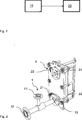
In
Dabei ist es vorzugsweise vorgesehen, dass die Dispersionseinrichtung
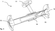
In der
In der
BezugszeichenlisteLIST OF REFERENCE NUMBERS
- 11
- Dispersionseinrichtung dispersion means
- 22
- Plattenwärmeüberträger Plate heat exchangers
- 1010
- Schritt des Mischens Step of mixing
- 1111
- sekundärer Eingang der Dispersionseinrichtung secondary input of the dispersion device
- 1212
- primärer Eingang der Dispersionseinrichtung primary input of the dispersion device
- 1313
- Ausgang der Dispersionseinrichtung Output of the dispersion device
- 1414
- Bereich der Mischdüse Area of the mixing nozzle
- 1515
- Kammer chamber
- 2020
- Schritt der Wärmeübertragung Step of heat transfer
- 2121
- Ausgang an einer Wärmeübertragungseinrichtung Output at a heat transfer device
- 2222
- Eingang an einer Wärmeübertragungseinrichtung Entrance to a heat transfer device
Claims (12)
Priority Applications (1)
| Application Number | Priority Date | Filing Date | Title |
|---|---|---|---|
| DE102016217841.5A DE102016217841B4 (en) | 2016-09-19 | 2016-09-19 | System consisting of a dispersion device and a heat transfer device |
Applications Claiming Priority (1)
| Application Number | Priority Date | Filing Date | Title |
|---|---|---|---|
| DE102016217841.5A DE102016217841B4 (en) | 2016-09-19 | 2016-09-19 | System consisting of a dispersion device and a heat transfer device |
Publications (2)
| Publication Number | Publication Date |
|---|---|
| DE102016217841A1 true DE102016217841A1 (en) | 2018-03-22 |
| DE102016217841B4 DE102016217841B4 (en) | 2024-01-18 |
Family
ID=61302258
Family Applications (1)
| Application Number | Title | Priority Date | Filing Date |
|---|---|---|---|
| DE102016217841.5A Active DE102016217841B4 (en) | 2016-09-19 | 2016-09-19 | System consisting of a dispersion device and a heat transfer device |
Country Status (1)
| Country | Link |
|---|---|
| DE (1) | DE102016217841B4 (en) |
Citations (6)
| Publication number | Priority date | Publication date | Assignee | Title |
|---|---|---|---|---|
| EP0172375A1 (en) | 1984-07-09 | 1986-02-26 | VTH AG Verfahrenstechnik für Heizung | Device for heating a fluid and for cleaning the flue gases of firing equipments |
| DE10218278B4 (en) | 2002-04-19 | 2005-12-01 | Fraunhofer-Gesellschaft zur Förderung der angewandten Forschung e.V. | microreactor |
| US20080190862A1 (en) | 2005-06-03 | 2008-08-14 | Ultrasound Brewery | Solution Reactor and Method for Solution Reaction |
| DE202010008826U1 (en) | 2010-10-18 | 2010-12-16 | Michelbach, Ludwig | Cooling module |
| DE102011110039A1 (en) | 2011-08-12 | 2013-02-14 | Thomas Pollmeier | Ventilation system with coolable PCM heat exchanger and method for operating the ventilation system |
| US20140335002A1 (en) | 2013-05-09 | 2014-11-13 | Paul Scott Northrop | Separating carbon dioxide and hydrogen sulfide from a natural gas stream using co-current contacting systems |
Family Cites Families (2)
| Publication number | Priority date | Publication date | Assignee | Title |
|---|---|---|---|---|
| DE19956378B4 (en) | 1999-11-24 | 2005-12-01 | Daimlerchrysler Ag | Method for introducing various gaseous and / or liquid operating materials into a reaction space |
| WO2008052361A1 (en) | 2006-11-03 | 2008-05-08 | Nxtgen Emission Controls Inc. | Fuel processor |
-
2016
- 2016-09-19 DE DE102016217841.5A patent/DE102016217841B4/en active Active
Patent Citations (6)
| Publication number | Priority date | Publication date | Assignee | Title |
|---|---|---|---|---|
| EP0172375A1 (en) | 1984-07-09 | 1986-02-26 | VTH AG Verfahrenstechnik für Heizung | Device for heating a fluid and for cleaning the flue gases of firing equipments |
| DE10218278B4 (en) | 2002-04-19 | 2005-12-01 | Fraunhofer-Gesellschaft zur Förderung der angewandten Forschung e.V. | microreactor |
| US20080190862A1 (en) | 2005-06-03 | 2008-08-14 | Ultrasound Brewery | Solution Reactor and Method for Solution Reaction |
| DE202010008826U1 (en) | 2010-10-18 | 2010-12-16 | Michelbach, Ludwig | Cooling module |
| DE102011110039A1 (en) | 2011-08-12 | 2013-02-14 | Thomas Pollmeier | Ventilation system with coolable PCM heat exchanger and method for operating the ventilation system |
| US20140335002A1 (en) | 2013-05-09 | 2014-11-13 | Paul Scott Northrop | Separating carbon dioxide and hydrogen sulfide from a natural gas stream using co-current contacting systems |
Also Published As
| Publication number | Publication date |
|---|---|
| DE102016217841B4 (en) | 2024-01-18 |
Similar Documents
| Publication | Publication Date | Title |
|---|---|---|
| DE69917433T2 (en) | METHOD AND DEVICE FOR PRODUCING LIQUID DISPERSES SYSTEMS IN LIQUIDS | |
| EP1426099B1 (en) | Static mixer and method | |
| EP2851118B1 (en) | Device for mixing and for heat exchange and method for its production | |
| EP1311341B1 (en) | Method and statistical micromixer for mixing at least two liquids | |
| DE102005037026B4 (en) | cavitation mixer | |
| EP1510247B1 (en) | Static mixer with polymorphous structure | |
| DE69416846T2 (en) | DEVICE FOR DISTRIBUTING, MIXING AND TAKING A MONOPHASIC FLUIDUM FOR SOLID PARTICLE BEDS | |
| DE69825569T3 (en) | homogenization | |
| WO2001062373A1 (en) | Cavitation mixer | |
| DE10019759C2 (en) | Static mixing system | |
| EP3408014A1 (en) | Hollow chamber x-mixer heat exchanger | |
| EP2368625A1 (en) | Method and device for dispersion | |
| EP2281626A2 (en) | Method and device for emulsifying liquids | |
| EP2321538B1 (en) | Microfluid device | |
| DE102017210271A1 (en) | Heat exchanger, in particular exhaust gas heat exchanger, for a motor vehicle | |
| DE102016217841A1 (en) | System comprising a dispersion device and a heat transfer device, a dispersion device and a method for the transfer of thermal energy | |
| DE102016223703A1 (en) | Heat exchanger, in particular exhaust gas heat exchanger, for a motor vehicle | |
| DE2648086A1 (en) | Static mixer for low and high viscosity liquids - having helically twisted blades in a tubular housing | |
| DE3920123C1 (en) | ||
| DE102015122219A1 (en) | Nozzle device for hot gas welding | |
| DE202016008276U1 (en) | Heat exchanger, in particular exhaust gas heat exchanger, for a motor vehicle | |
| DE102010017523A1 (en) | Method and mixing device for mixing two fluids and their use | |
| DE102012104053B3 (en) | emulsifying | |
| EP3187253A1 (en) | Cavitation reactor for treating a flowable substance | |
| DE2130134C (en) | Device for mixing, homogenizing and emulsifying |
Legal Events
| Date | Code | Title | Description |
|---|---|---|---|
| R012 | Request for examination validly filed | ||
| R082 | Change of representative |
Representative=s name: KUTZENBERGER WOLFF & PARTNER PATENTANWALTSPART, DE |
|
| R083 | Amendment of/additions to inventor(s) | ||
| R016 | Response to examination communication | ||
| R016 | Response to examination communication | ||
| R081 | Change of applicant/patentee |
Owner name: IFL INGENIEURBUERO FUER LEICHTBAU GMBH & CO KG, DE Free format text: FORMER OWNER: TECHNISCHE UNIVERSITAET DRESDEN, 01069 DRESDEN, DE |
|
| R082 | Change of representative |
Representative=s name: KRAUSE, WOLFGANG, DR., DE |
|
| R016 | Response to examination communication | ||
| R018 | Grant decision by examination section/examining division | ||
| R020 | Patent grant now final |