DE102015225718B4 - Method of reducing drive shaft vibration of an eco-friendly vehicle - Google Patents
Method of reducing drive shaft vibration of an eco-friendly vehicle Download PDFInfo
- Publication number
- DE102015225718B4 DE102015225718B4 DE102015225718.5A DE102015225718A DE102015225718B4 DE 102015225718 B4 DE102015225718 B4 DE 102015225718B4 DE 102015225718 A DE102015225718 A DE 102015225718A DE 102015225718 B4 DE102015225718 B4 DE 102015225718B4
- Authority
- DE
- Germany
- Prior art keywords
- torque
- drive shaft
- model
- speed
- model speed
- Prior art date
- Legal status (The legal status is an assumption and is not a legal conclusion. Google has not performed a legal analysis and makes no representation as to the accuracy of the status listed.)
- Active
Links
- 238000000034 method Methods 0.000 title claims abstract description 57
- 238000012546 transfer Methods 0.000 claims abstract description 28
- 230000009467 reduction Effects 0.000 claims abstract description 15
- 238000004364 calculation method Methods 0.000 claims description 134
- 230000008859 change Effects 0.000 claims description 14
- 239000007858 starting material Substances 0.000 claims description 14
- 230000005540 biological transmission Effects 0.000 claims description 11
- 238000010586 diagram Methods 0.000 description 6
- 230000001133 acceleration Effects 0.000 description 4
- 230000003111 delayed effect Effects 0.000 description 4
- 239000000446 fuel Substances 0.000 description 4
- 230000008901 benefit Effects 0.000 description 3
- 238000012937 correction Methods 0.000 description 3
- 230000008569 process Effects 0.000 description 3
- 230000002238 attenuated effect Effects 0.000 description 2
- 238000005516 engineering process Methods 0.000 description 2
- 238000000605 extraction Methods 0.000 description 2
- 238000012545 processing Methods 0.000 description 2
- 238000011084 recovery Methods 0.000 description 2
- UFHFLCQGNIYNRP-UHFFFAOYSA-N Hydrogen Chemical compound [H][H] UFHFLCQGNIYNRP-UHFFFAOYSA-N 0.000 description 1
- 230000000703 anti-shock Effects 0.000 description 1
- 238000007796 conventional method Methods 0.000 description 1
- 230000002950 deficient Effects 0.000 description 1
- 230000000881 depressing effect Effects 0.000 description 1
- 238000013461 design Methods 0.000 description 1
- 230000004069 differentiation Effects 0.000 description 1
- 238000007599 discharging Methods 0.000 description 1
- 230000000694 effects Effects 0.000 description 1
- 230000005611 electricity Effects 0.000 description 1
- 230000008030 elimination Effects 0.000 description 1
- 238000003379 elimination reaction Methods 0.000 description 1
- 230000036541 health Effects 0.000 description 1
- 229910052739 hydrogen Inorganic materials 0.000 description 1
- 239000001257 hydrogen Substances 0.000 description 1
- 238000013017 mechanical damping Methods 0.000 description 1
- 230000007246 mechanism Effects 0.000 description 1
- 230000000116 mitigating effect Effects 0.000 description 1
- 239000003208 petroleum Substances 0.000 description 1
- 230000035939 shock Effects 0.000 description 1
Images


Classifications
-
- B—PERFORMING OPERATIONS; TRANSPORTING
- B60—VEHICLES IN GENERAL
- B60L—PROPULSION OF ELECTRICALLY-PROPELLED VEHICLES; SUPPLYING ELECTRIC POWER FOR AUXILIARY EQUIPMENT OF ELECTRICALLY-PROPELLED VEHICLES; ELECTRODYNAMIC BRAKE SYSTEMS FOR VEHICLES IN GENERAL; MAGNETIC SUSPENSION OR LEVITATION FOR VEHICLES; MONITORING OPERATING VARIABLES OF ELECTRICALLY-PROPELLED VEHICLES; ELECTRIC SAFETY DEVICES FOR ELECTRICALLY-PROPELLED VEHICLES
- B60L15/00—Methods, circuits, or devices for controlling the traction-motor speed of electrically-propelled vehicles
- B60L15/20—Methods, circuits, or devices for controlling the traction-motor speed of electrically-propelled vehicles for control of the vehicle or its driving motor to achieve a desired performance, e.g. speed, torque, programmed variation of speed
-
- B—PERFORMING OPERATIONS; TRANSPORTING
- B60—VEHICLES IN GENERAL
- B60K—ARRANGEMENT OR MOUNTING OF PROPULSION UNITS OR OF TRANSMISSIONS IN VEHICLES; ARRANGEMENT OR MOUNTING OF PLURAL DIVERSE PRIME-MOVERS IN VEHICLES; AUXILIARY DRIVES FOR VEHICLES; INSTRUMENTATION OR DASHBOARDS FOR VEHICLES; ARRANGEMENTS IN CONNECTION WITH COOLING, AIR INTAKE, GAS EXHAUST OR FUEL SUPPLY OF PROPULSION UNITS IN VEHICLES
- B60K6/00—Arrangement or mounting of plural diverse prime-movers for mutual or common propulsion, e.g. hybrid propulsion systems comprising electric motors and internal combustion engines ; Control systems therefor, i.e. systems controlling two or more prime movers, or controlling one of these prime movers and any of the transmission, drive or drive units
- B60K6/20—Arrangement or mounting of plural diverse prime-movers for mutual or common propulsion, e.g. hybrid propulsion systems comprising electric motors and internal combustion engines ; Control systems therefor, i.e. systems controlling two or more prime movers, or controlling one of these prime movers and any of the transmission, drive or drive units the prime-movers consisting of electric motors and internal combustion engines, e.g. HEVs
- B60K6/42—Arrangement or mounting of plural diverse prime-movers for mutual or common propulsion, e.g. hybrid propulsion systems comprising electric motors and internal combustion engines ; Control systems therefor, i.e. systems controlling two or more prime movers, or controlling one of these prime movers and any of the transmission, drive or drive units the prime-movers consisting of electric motors and internal combustion engines, e.g. HEVs characterised by the architecture of the hybrid electric vehicle
- B60K6/48—Parallel type
-
- B—PERFORMING OPERATIONS; TRANSPORTING
- B60—VEHICLES IN GENERAL
- B60W—CONJOINT CONTROL OF VEHICLE SUB-UNITS OF DIFFERENT TYPE OR DIFFERENT FUNCTION; CONTROL SYSTEMS SPECIALLY ADAPTED FOR HYBRID VEHICLES; ROAD VEHICLE DRIVE CONTROL SYSTEMS FOR PURPOSES NOT RELATED TO THE CONTROL OF A PARTICULAR SUB-UNIT
- B60W10/00—Conjoint control of vehicle sub-units of different type or different function
- B60W10/04—Conjoint control of vehicle sub-units of different type or different function including control of propulsion units
- B60W10/06—Conjoint control of vehicle sub-units of different type or different function including control of propulsion units including control of combustion engines
-
- B—PERFORMING OPERATIONS; TRANSPORTING
- B60—VEHICLES IN GENERAL
- B60W—CONJOINT CONTROL OF VEHICLE SUB-UNITS OF DIFFERENT TYPE OR DIFFERENT FUNCTION; CONTROL SYSTEMS SPECIALLY ADAPTED FOR HYBRID VEHICLES; ROAD VEHICLE DRIVE CONTROL SYSTEMS FOR PURPOSES NOT RELATED TO THE CONTROL OF A PARTICULAR SUB-UNIT
- B60W10/00—Conjoint control of vehicle sub-units of different type or different function
- B60W10/04—Conjoint control of vehicle sub-units of different type or different function including control of propulsion units
- B60W10/08—Conjoint control of vehicle sub-units of different type or different function including control of propulsion units including control of electric propulsion units, e.g. motors or generators
-
- B—PERFORMING OPERATIONS; TRANSPORTING
- B60—VEHICLES IN GENERAL
- B60W—CONJOINT CONTROL OF VEHICLE SUB-UNITS OF DIFFERENT TYPE OR DIFFERENT FUNCTION; CONTROL SYSTEMS SPECIALLY ADAPTED FOR HYBRID VEHICLES; ROAD VEHICLE DRIVE CONTROL SYSTEMS FOR PURPOSES NOT RELATED TO THE CONTROL OF A PARTICULAR SUB-UNIT
- B60W20/00—Control systems specially adapted for hybrid vehicles
- B60W20/10—Controlling the power contribution of each of the prime movers to meet required power demand
- B60W20/15—Control strategies specially adapted for achieving a particular effect
-
- B—PERFORMING OPERATIONS; TRANSPORTING
- B60—VEHICLES IN GENERAL
- B60W—CONJOINT CONTROL OF VEHICLE SUB-UNITS OF DIFFERENT TYPE OR DIFFERENT FUNCTION; CONTROL SYSTEMS SPECIALLY ADAPTED FOR HYBRID VEHICLES; ROAD VEHICLE DRIVE CONTROL SYSTEMS FOR PURPOSES NOT RELATED TO THE CONTROL OF A PARTICULAR SUB-UNIT
- B60W30/00—Purposes of road vehicle drive control systems not related to the control of a particular sub-unit, e.g. of systems using conjoint control of vehicle sub-units
- B60W30/18—Propelling the vehicle
- B60W30/20—Reducing vibrations in the driveline
-
- B—PERFORMING OPERATIONS; TRANSPORTING
- B60—VEHICLES IN GENERAL
- B60K—ARRANGEMENT OR MOUNTING OF PROPULSION UNITS OR OF TRANSMISSIONS IN VEHICLES; ARRANGEMENT OR MOUNTING OF PLURAL DIVERSE PRIME-MOVERS IN VEHICLES; AUXILIARY DRIVES FOR VEHICLES; INSTRUMENTATION OR DASHBOARDS FOR VEHICLES; ARRANGEMENTS IN CONNECTION WITH COOLING, AIR INTAKE, GAS EXHAUST OR FUEL SUPPLY OF PROPULSION UNITS IN VEHICLES
- B60K6/00—Arrangement or mounting of plural diverse prime-movers for mutual or common propulsion, e.g. hybrid propulsion systems comprising electric motors and internal combustion engines ; Control systems therefor, i.e. systems controlling two or more prime movers, or controlling one of these prime movers and any of the transmission, drive or drive units
- B60K6/20—Arrangement or mounting of plural diverse prime-movers for mutual or common propulsion, e.g. hybrid propulsion systems comprising electric motors and internal combustion engines ; Control systems therefor, i.e. systems controlling two or more prime movers, or controlling one of these prime movers and any of the transmission, drive or drive units the prime-movers consisting of electric motors and internal combustion engines, e.g. HEVs
- B60K6/42—Arrangement or mounting of plural diverse prime-movers for mutual or common propulsion, e.g. hybrid propulsion systems comprising electric motors and internal combustion engines ; Control systems therefor, i.e. systems controlling two or more prime movers, or controlling one of these prime movers and any of the transmission, drive or drive units the prime-movers consisting of electric motors and internal combustion engines, e.g. HEVs characterised by the architecture of the hybrid electric vehicle
- B60K6/48—Parallel type
- B60K2006/4825—Electric machine connected or connectable to gearbox input shaft
-
- B—PERFORMING OPERATIONS; TRANSPORTING
- B60—VEHICLES IN GENERAL
- B60L—PROPULSION OF ELECTRICALLY-PROPELLED VEHICLES; SUPPLYING ELECTRIC POWER FOR AUXILIARY EQUIPMENT OF ELECTRICALLY-PROPELLED VEHICLES; ELECTRODYNAMIC BRAKE SYSTEMS FOR VEHICLES IN GENERAL; MAGNETIC SUSPENSION OR LEVITATION FOR VEHICLES; MONITORING OPERATING VARIABLES OF ELECTRICALLY-PROPELLED VEHICLES; ELECTRIC SAFETY DEVICES FOR ELECTRICALLY-PROPELLED VEHICLES
- B60L2240/00—Control parameters of input or output; Target parameters
- B60L2240/10—Vehicle control parameters
- B60L2240/12—Speed
-
- B—PERFORMING OPERATIONS; TRANSPORTING
- B60—VEHICLES IN GENERAL
- B60L—PROPULSION OF ELECTRICALLY-PROPELLED VEHICLES; SUPPLYING ELECTRIC POWER FOR AUXILIARY EQUIPMENT OF ELECTRICALLY-PROPELLED VEHICLES; ELECTRODYNAMIC BRAKE SYSTEMS FOR VEHICLES IN GENERAL; MAGNETIC SUSPENSION OR LEVITATION FOR VEHICLES; MONITORING OPERATING VARIABLES OF ELECTRICALLY-PROPELLED VEHICLES; ELECTRIC SAFETY DEVICES FOR ELECTRICALLY-PROPELLED VEHICLES
- B60L2240/00—Control parameters of input or output; Target parameters
- B60L2240/40—Drive Train control parameters
- B60L2240/42—Drive Train control parameters related to electric machines
- B60L2240/423—Torque
-
- B—PERFORMING OPERATIONS; TRANSPORTING
- B60—VEHICLES IN GENERAL
- B60L—PROPULSION OF ELECTRICALLY-PROPELLED VEHICLES; SUPPLYING ELECTRIC POWER FOR AUXILIARY EQUIPMENT OF ELECTRICALLY-PROPELLED VEHICLES; ELECTRODYNAMIC BRAKE SYSTEMS FOR VEHICLES IN GENERAL; MAGNETIC SUSPENSION OR LEVITATION FOR VEHICLES; MONITORING OPERATING VARIABLES OF ELECTRICALLY-PROPELLED VEHICLES; ELECTRIC SAFETY DEVICES FOR ELECTRICALLY-PROPELLED VEHICLES
- B60L2240/00—Control parameters of input or output; Target parameters
- B60L2240/40—Drive Train control parameters
- B60L2240/48—Drive Train control parameters related to transmissions
- B60L2240/486—Operating parameters
-
- B—PERFORMING OPERATIONS; TRANSPORTING
- B60—VEHICLES IN GENERAL
- B60L—PROPULSION OF ELECTRICALLY-PROPELLED VEHICLES; SUPPLYING ELECTRIC POWER FOR AUXILIARY EQUIPMENT OF ELECTRICALLY-PROPELLED VEHICLES; ELECTRODYNAMIC BRAKE SYSTEMS FOR VEHICLES IN GENERAL; MAGNETIC SUSPENSION OR LEVITATION FOR VEHICLES; MONITORING OPERATING VARIABLES OF ELECTRICALLY-PROPELLED VEHICLES; ELECTRIC SAFETY DEVICES FOR ELECTRICALLY-PROPELLED VEHICLES
- B60L2260/00—Operating Modes
- B60L2260/40—Control modes
- B60L2260/44—Control modes by parameter estimation
-
- B—PERFORMING OPERATIONS; TRANSPORTING
- B60—VEHICLES IN GENERAL
- B60W—CONJOINT CONTROL OF VEHICLE SUB-UNITS OF DIFFERENT TYPE OR DIFFERENT FUNCTION; CONTROL SYSTEMS SPECIALLY ADAPTED FOR HYBRID VEHICLES; ROAD VEHICLE DRIVE CONTROL SYSTEMS FOR PURPOSES NOT RELATED TO THE CONTROL OF A PARTICULAR SUB-UNIT
- B60W30/00—Purposes of road vehicle drive control systems not related to the control of a particular sub-unit, e.g. of systems using conjoint control of vehicle sub-units
- B60W30/18—Propelling the vehicle
- B60W30/20—Reducing vibrations in the driveline
- B60W2030/206—Reducing vibrations in the driveline related or induced by the engine
-
- B—PERFORMING OPERATIONS; TRANSPORTING
- B60—VEHICLES IN GENERAL
- B60W—CONJOINT CONTROL OF VEHICLE SUB-UNITS OF DIFFERENT TYPE OR DIFFERENT FUNCTION; CONTROL SYSTEMS SPECIALLY ADAPTED FOR HYBRID VEHICLES; ROAD VEHICLE DRIVE CONTROL SYSTEMS FOR PURPOSES NOT RELATED TO THE CONTROL OF A PARTICULAR SUB-UNIT
- B60W50/00—Details of control systems for road vehicle drive control not related to the control of a particular sub-unit, e.g. process diagnostic or vehicle driver interfaces
- B60W2050/0001—Details of the control system
- B60W2050/0002—Automatic control, details of type of controller or control system architecture
- B60W2050/0008—Feedback, closed loop systems or details of feedback error signal
-
- B—PERFORMING OPERATIONS; TRANSPORTING
- B60—VEHICLES IN GENERAL
- B60W—CONJOINT CONTROL OF VEHICLE SUB-UNITS OF DIFFERENT TYPE OR DIFFERENT FUNCTION; CONTROL SYSTEMS SPECIALLY ADAPTED FOR HYBRID VEHICLES; ROAD VEHICLE DRIVE CONTROL SYSTEMS FOR PURPOSES NOT RELATED TO THE CONTROL OF A PARTICULAR SUB-UNIT
- B60W50/00—Details of control systems for road vehicle drive control not related to the control of a particular sub-unit, e.g. process diagnostic or vehicle driver interfaces
- B60W2050/0001—Details of the control system
- B60W2050/0019—Control system elements or transfer functions
- B60W2050/0028—Mathematical models, e.g. for simulation
- B60W2050/0037—Mathematical models of vehicle sub-units
- B60W2050/0041—Mathematical models of vehicle sub-units of the drive line
-
- B—PERFORMING OPERATIONS; TRANSPORTING
- B60—VEHICLES IN GENERAL
- B60W—CONJOINT CONTROL OF VEHICLE SUB-UNITS OF DIFFERENT TYPE OR DIFFERENT FUNCTION; CONTROL SYSTEMS SPECIALLY ADAPTED FOR HYBRID VEHICLES; ROAD VEHICLE DRIVE CONTROL SYSTEMS FOR PURPOSES NOT RELATED TO THE CONTROL OF A PARTICULAR SUB-UNIT
- B60W2510/00—Input parameters relating to a particular sub-units
- B60W2510/08—Electric propulsion units
- B60W2510/081—Speed
-
- B—PERFORMING OPERATIONS; TRANSPORTING
- B60—VEHICLES IN GENERAL
- B60W—CONJOINT CONTROL OF VEHICLE SUB-UNITS OF DIFFERENT TYPE OR DIFFERENT FUNCTION; CONTROL SYSTEMS SPECIALLY ADAPTED FOR HYBRID VEHICLES; ROAD VEHICLE DRIVE CONTROL SYSTEMS FOR PURPOSES NOT RELATED TO THE CONTROL OF A PARTICULAR SUB-UNIT
- B60W2510/00—Input parameters relating to a particular sub-units
- B60W2510/10—Change speed gearings
- B60W2510/104—Output speed
- B60W2510/1045—Output speed change rate
-
- B—PERFORMING OPERATIONS; TRANSPORTING
- B60—VEHICLES IN GENERAL
- B60W—CONJOINT CONTROL OF VEHICLE SUB-UNITS OF DIFFERENT TYPE OR DIFFERENT FUNCTION; CONTROL SYSTEMS SPECIALLY ADAPTED FOR HYBRID VEHICLES; ROAD VEHICLE DRIVE CONTROL SYSTEMS FOR PURPOSES NOT RELATED TO THE CONTROL OF A PARTICULAR SUB-UNIT
- B60W2710/00—Output or target parameters relating to a particular sub-units
- B60W2710/06—Combustion engines, Gas turbines
- B60W2710/0666—Engine torque
-
- B—PERFORMING OPERATIONS; TRANSPORTING
- B60—VEHICLES IN GENERAL
- B60W—CONJOINT CONTROL OF VEHICLE SUB-UNITS OF DIFFERENT TYPE OR DIFFERENT FUNCTION; CONTROL SYSTEMS SPECIALLY ADAPTED FOR HYBRID VEHICLES; ROAD VEHICLE DRIVE CONTROL SYSTEMS FOR PURPOSES NOT RELATED TO THE CONTROL OF A PARTICULAR SUB-UNIT
- B60W2710/00—Output or target parameters relating to a particular sub-units
- B60W2710/08—Electric propulsion units
- B60W2710/083—Torque
-
- B—PERFORMING OPERATIONS; TRANSPORTING
- B60—VEHICLES IN GENERAL
- B60W—CONJOINT CONTROL OF VEHICLE SUB-UNITS OF DIFFERENT TYPE OR DIFFERENT FUNCTION; CONTROL SYSTEMS SPECIALLY ADAPTED FOR HYBRID VEHICLES; ROAD VEHICLE DRIVE CONTROL SYSTEMS FOR PURPOSES NOT RELATED TO THE CONTROL OF A PARTICULAR SUB-UNIT
- B60W2710/00—Output or target parameters relating to a particular sub-units
- B60W2710/10—Change speed gearings
- B60W2710/1022—Input torque
-
- B—PERFORMING OPERATIONS; TRANSPORTING
- B60—VEHICLES IN GENERAL
- B60Y—INDEXING SCHEME RELATING TO ASPECTS CROSS-CUTTING VEHICLE TECHNOLOGY
- B60Y2200/00—Type of vehicle
- B60Y2200/90—Vehicles comprising electric prime movers
- B60Y2200/92—Hybrid vehicles
-
- Y—GENERAL TAGGING OF NEW TECHNOLOGICAL DEVELOPMENTS; GENERAL TAGGING OF CROSS-SECTIONAL TECHNOLOGIES SPANNING OVER SEVERAL SECTIONS OF THE IPC; TECHNICAL SUBJECTS COVERED BY FORMER USPC CROSS-REFERENCE ART COLLECTIONS [XRACs] AND DIGESTS
- Y02—TECHNOLOGIES OR APPLICATIONS FOR MITIGATION OR ADAPTATION AGAINST CLIMATE CHANGE
- Y02T—CLIMATE CHANGE MITIGATION TECHNOLOGIES RELATED TO TRANSPORTATION
- Y02T10/00—Road transport of goods or passengers
- Y02T10/10—Internal combustion engine [ICE] based vehicles
- Y02T10/40—Engine management systems
-
- Y—GENERAL TAGGING OF NEW TECHNOLOGICAL DEVELOPMENTS; GENERAL TAGGING OF CROSS-SECTIONAL TECHNOLOGIES SPANNING OVER SEVERAL SECTIONS OF THE IPC; TECHNICAL SUBJECTS COVERED BY FORMER USPC CROSS-REFERENCE ART COLLECTIONS [XRACs] AND DIGESTS
- Y02—TECHNOLOGIES OR APPLICATIONS FOR MITIGATION OR ADAPTATION AGAINST CLIMATE CHANGE
- Y02T—CLIMATE CHANGE MITIGATION TECHNOLOGIES RELATED TO TRANSPORTATION
- Y02T10/00—Road transport of goods or passengers
- Y02T10/60—Other road transportation technologies with climate change mitigation effect
- Y02T10/62—Hybrid vehicles
-
- Y—GENERAL TAGGING OF NEW TECHNOLOGICAL DEVELOPMENTS; GENERAL TAGGING OF CROSS-SECTIONAL TECHNOLOGIES SPANNING OVER SEVERAL SECTIONS OF THE IPC; TECHNICAL SUBJECTS COVERED BY FORMER USPC CROSS-REFERENCE ART COLLECTIONS [XRACs] AND DIGESTS
- Y02—TECHNOLOGIES OR APPLICATIONS FOR MITIGATION OR ADAPTATION AGAINST CLIMATE CHANGE
- Y02T—CLIMATE CHANGE MITIGATION TECHNOLOGIES RELATED TO TRANSPORTATION
- Y02T10/00—Road transport of goods or passengers
- Y02T10/60—Other road transportation technologies with climate change mitigation effect
- Y02T10/64—Electric machine technologies in electromobility
-
- Y—GENERAL TAGGING OF NEW TECHNOLOGICAL DEVELOPMENTS; GENERAL TAGGING OF CROSS-SECTIONAL TECHNOLOGIES SPANNING OVER SEVERAL SECTIONS OF THE IPC; TECHNICAL SUBJECTS COVERED BY FORMER USPC CROSS-REFERENCE ART COLLECTIONS [XRACs] AND DIGESTS
- Y02—TECHNOLOGIES OR APPLICATIONS FOR MITIGATION OR ADAPTATION AGAINST CLIMATE CHANGE
- Y02T—CLIMATE CHANGE MITIGATION TECHNOLOGIES RELATED TO TRANSPORTATION
- Y02T10/00—Road transport of goods or passengers
- Y02T10/60—Other road transportation technologies with climate change mitigation effect
- Y02T10/72—Electric energy management in electromobility
Landscapes
- Engineering & Computer Science (AREA)
- Transportation (AREA)
- Mechanical Engineering (AREA)
- Chemical & Material Sciences (AREA)
- Combustion & Propulsion (AREA)
- Automation & Control Theory (AREA)
- Power Engineering (AREA)
- Electric Propulsion And Braking For Vehicles (AREA)
- Physics & Mathematics (AREA)
- Human Computer Interaction (AREA)
- General Physics & Mathematics (AREA)
- Mathematical Physics (AREA)
Abstract
Verfahren zum Reduzieren der Vibration einer Antriebswelle eines umweltfreundlichen Fahrzeugs, das Verfahren umfassend:• Erfassen einer tatsächlichen Geschwindigkeit der Antriebswelle von der ein Drehmoment eines Antriebsmotors, der das Fahrzeug antreibt, ausgegeben wird;• Berechnen einer Modellgeschwindigkeit der Antriebswelle;• Erhalten einer Vibrationskomponente basierend auf einer Abweichung zwischen der erfassten tatsächlichen Geschwindigkeit der Antriebswelle und der errechneten Modellgeschwindigkeit; und• Erzeugen eines Vibrationsreduzierungs-Ausgleichsdrehmoments zum Reduzieren der Vibration der Antriebswelle aus der Vibrationskomponente,wobei der Berechnungsschritt umfasst:◯ Berechnen eines benötigten Ausgabedrehmoments der Antriebswelle basierend auf einem an die Antriebswelle gelieferten Drehmoment;◯ Schätzen eines Eingabedrehmoments der Antriebswelle, welches der Antriebswelle mithilfe der tatsächlichen Geschwindigkeit der Antriebswelle eingegeben wird;◯ Schätzen eines Störmoments mithilfe des benötigten Ausgabedrehmoments der Antriebswelle und des Eingabedrehmoments der Antriebswelle;◯ Berechnen eines Modelleingabedrehmoments der Antriebswelle, welches erhalten wird durch Hinzuaddieren des Störmoments zu dem benötigten Ausgabedrehmoment der Antriebswelle unter Verwendung des geschätzten Störmoments; undBerechnen der Modellgeschwindigkeit unter Verwendung eines Antriebswellenmodells, welches das Eingabedrehmoment des Antriebswellenmodells als Eingabewert aufnimmt dadurch gekennzeichnet, dassder Schritt zum Schätzen des Eingabedrehmoments der Antriebswelle umfasst: Schätzen des Eingabedrehmoments der Antriebswelle unter Verwendung einer Transferfunktion des Antriebswellenmodells und der tatsächlichen Geschwindigkeit (ω) der Antriebswelle,wobei das Eingabedrehmoment der Drehwelle (Tacc') mithilfe der folgenden Gleichung abgeschätzt wird: Tacc' = Q(s) × ω/Gm(s), bei der Q(s) eine Transferfunktion eines Filters ist, und Gm(s) die Transferfunktion des Antriebswellenmodels ist.A method for reducing vibration of a drive shaft of an environmentally friendly vehicle, the method comprising:• detecting an actual speed of the drive shaft from which torque of a drive motor driving the vehicle is output;• calculating a model speed of the drive shaft;• obtaining a vibration component based on a deviation between the detected actual drive shaft speed and the calculated model speed; and• generating a vibration reduction compensation torque for reducing vibration of the drive shaft from the vibration component,wherein the calculating step comprises:◯ calculating a required output torque of the drive shaft based on a torque supplied to the drive shaft;◯ estimating an input torque of the drive shaft, which is applied to the drive shaft using the actual drive shaft speed is input;◯ estimating a disturbance torque using the required drive shaft output torque and the input shaft torque;◯ calculating a model input shaft torque obtained by adding the disturbance torque to the required drive shaft output torque using the estimated disturbance torque; andcalculating the model speed using a driveshaft model which takes the input torque of the driveshaft model as an input characterized in thatthe step of estimating the input torque of the driveshaft comprises: estimating the input torque of the driveshaft using a transfer function of the driveshaft model and the actual speed (ω) of the driveshaft, where the input torque of the rotary shaft (Tacc') is estimated using the following equation: Tacc'=Q(s)×ω/Gm(s), where Q(s) is a transfer function of a filter and Gm(s) is the transfer function of the driveshaft model.
Description
TECHNISCHES GEBIETTECHNICAL AREA
Die vorliegende Offenbarung betrifft ein Verfahren zum Reduzieren einer Antriebswellenvibration eines umweltfreundlichen Fahrzeugs. Insbesondere betrifft die vorliegende Offenbarung ein Steuerverfahren zum Reduzieren der Antriebswellenvibration eines umweltfreundlichen Fahrzeugs bei dem eine von einer Antriebswelle erzeugte Vibration mithilfe eines mit der Antriebswelle mechanisch verbundenen Motors verringert wird.The present disclosure relates to a method for reducing drive shaft vibration of an eco-friendly vehicle. More particularly, the present disclosure relates to a control method for reducing drive shaft vibration of an eco-friendly vehicle, in which vibration generated from a drive shaft is reduced using a motor mechanically connected to the drive shaft.
HINTERGRUNDBACKGROUND
Im Allgemeinen wird ein umweltfreundliches Fahrzeug wie ein reines Elektrofahrzeug (EV) oder ein Hybrid-Elektrofahrzeug (HEV) mit einem als eine Antriebsquelle verwendeten Elektromotor angetrieben.In general, an environmentally friendly vehicle such as a pure electric vehicle (EV) or a hybrid electric vehicle (HEV) is driven with an electric motor used as a drive source.
Das reine Elektrofahrzeug wird nur mithilfe der Leistung des Elektromotors angetrieben, der über einen Batteriestrom betrieben wird, und das HEV wird angetrieben durch die effiziente Kombination der Energie eines Motors (Engl. engine: Motor bzw. Maschine) und der Energie des Elektromotors.The pure electric vehicle is powered only by the power of the electric motor, which runs on battery power, and the HEV is powered by the efficient combination of the energy of an engine and the energy of the electric motor.
Andere Beispiele des umweltfreundlichen Fahrzeugs können ein Brennstoffzellenfahrzeug (Fuel Cell Electric Vehicle, FCEV) umfassen, das angetrieben wird durch Betreiben eines Elektromotors, der von einer Brennstoffzelle erzeugte Energie nutzt.Other examples of the eco-friendly vehicle may include a fuel cell electric vehicle (FCEV) that is powered by operating an electric motor that uses energy generated by a fuel cell.
Das FCEV ist ebenfalls ein Fahrzeug, das mithilfe eines Elektromotors angetrieben wird, und kann grob zusammen mit dem EV und dem HEV als das EV, das von elektrischer Energie angetrieben wird, klassifiziert werden.The FCEV is also a vehicle powered by an electric motor, and can be roughly classified as the EV powered by electric energy along with the EV and the HEV.
Dabei fungiert die Batterie 18 als eine Antriebsquelle (Stromquelle) des Fahrzeugs und ist mit dem Antriebsmotor 13 durch den Wechselrichter 16 in einer ladbaren und entladbaren Weise verbunden, und der Wechselrichter 16 richtet einen Gleichstrom der Batterie 18 in einen dreiphasigen Wechselstrom um und speist den Antriebsmotor 13 mit dem umgerichteten Strom, um den Antriebsmotor 13 anzutreiben.At this time, the
Das BMS 19 sammelt Batteriestatusinformationen wie beispielsweise eine Spannung, einen Strom, eine Temperatur, einen Ladezustand (State of Charge, SOC) (%) usw. der Batterie 18. Dabei stellt das BMS 19 die gesammelten Batteriezustandsinformationen einem anderen Controller des Fahrzeugs bereit, oder ist mithilfe der Batteriezustandsinformationen direkt am Laden und Entladen der Batterie beteiligt.The
Wie in der Figur veranschaulicht umfasst das HEV einen Motor 11 und den Antriebsmotor 13, welche nacheinander angeordnet sind, um als Antriebsquelle zum Fahren eines Fahrzeugs zu fungieren, eine zwischen dem Motor 11 und dem Antriebsmotor 13 bereitgestellte Motorkupplung 12, um die Stromzufuhr herzustellen oder zu blockieren, das Getriebe 14 zum Verlagern der Energie des Motors 11 und des Antriebsmotors 13 und Übertragen der verlagerten Energie an eine Antriebswelle, und einen direkt mit dem Motor 11 verbundenen Starter-Generator (MG2) 15, der in der Lage ist, Strom zu übertragen.As illustrated in the figure, the HEV includes an
Die Motorkupplung 12 stellt zwischen den beiden Antriebsquellen eine stromleitende Verbindung her oder blockiert diese, das heißt zwischen dem Motor 11 und dem Antriebsmotor 13, die das Fahrzeug durch einen Schließ- oder Öffnungsvorgang antreiben.The
Zusätzlich ist eine Batterie 18, die als Stromquelle des Fahrzeugs fungiert, durch einen Wechselrichter 16 in einer ladbaren und entladbaren Weise mit dem Antriebsmotor 13 und dem Starter-Generator 15 verbunden. Der Wechselrichter 16 richtet einen Gleichstrom der Batterie 18 in einen dreiphasigen Wechselstrom um und speist den Antriebsmotor 13 und den Starter-Generator 15 mit dem umgerichteten Strom, um den Antriebsmotor 13 und den Starter-Generator 15 anzutreiben.In addition, a
Der Starter-Generator 15 übernimmt die Funktion eines Anlassers und eines Generators. Der Starter-Generator 15 startet den Motor 11 durch Übertragen dessen Energie an den Motor 11 mittels eines Kraftübertragungsmechanismus (zum Beispiel eines Keilriemens und einer Keilriemenscheibe) beim Fahren oder erzeugt Strom durch Aufnahme einer von dem Motor 11 übertragenen Rotationskraft und lädt die Batterie 18 mit während eines Erzeugungsvorgangs erzeugter elektrischer Energie.The
Jedoch ist es bei dem oben beschriebenen herkömmlichen umweltfreundlichen Fahrzeug nachteilig, dass ein mechanischer Dämpfungseffekt eines bestehenden Drehmomentwandlers nicht ausgenutzt werden kann.However, in the conventional environmentally friendly vehicle described above, there is a disadvantage that a mechanical damping effect of an existing torque converter cannot be utilized.
Darum bestand ein Problem im Hinblick auf einen verschlechterten Komfort und Bedienbarkeit aufgrund einer Vibrationsphänomens wie beispielsweise Schock oder Ruckeln (augenblickliche und schnelle Bewegung) zusammen mit dem Auftreten einer Antriebswellenvibration, wenn eine Geschwindigkeit verändert wird, wenn ein „tip-in/out“ Vorgang (Vorgang des Durchdrückens oder Freigebens des Gaspedals) ausgeführt wird und wenn eine Motorkupplung defekt ist, usw.Therefore, there has been a problem in terms of deteriorated comfort and operability due to a vibration phenomenon such as shock or jerking (instantaneous and quick movement) together with the occurrence of a drive shaft vibration when a speed is changed when a "tip-in/out" operation ( operation of depressing or releasing the accelerator pedal) and when an engine clutch is defective, etc.
Das bedeutet, dass eine Vibration einer Drehmomentquelle (Antriebsmaschine oder Motor), oder eine Vibration von außen selten abgeschwächt wird, da ein zwischen der Drehmomentquelle und dem Antriebssystem angeordneter Dämpfer klein ist und nicht verwendet wird.That is, since a damper interposed between the torque source and the drive system is small and is not used, vibration of a torque source (engine or engine), or vibration from the outside is rarely attenuated.
Eine Vibrationskomponente der Antriebswelle muss extrahiert werden, um die durch die Antriebswelle auftretende Vibration zu vermindern. Die Vibrationsminderungsleistung variiert gemäß der Genauigkeit der Extraktion der Vibrationskomponente, weshalb es wichtig ist, die Vibrationskomponente exakt zu extrahieren.A vibration component of the drive shaft needs to be extracted in order to reduce the vibration occurring through the drive shaft. The vibration reducing performance varies according to the accuracy of extraction of the vibration component, so it is important to accurately extract the vibration component.
Bei einer herkömmlichen Antiruckel-Steuertechnologie als Verfahren zum Unterdrücken einer Vibration einer Antriebswelle zum Lösen des obenstehenden Problems wird eine Abweichung zwischen einer Modellgeschwindigkeit und einer tatsächlichen Geschwindigkeit als Vibration erkannt, die Abweichung zwischen den Geschwindigkeiten wird mit einem bestimmten Wert multipliziert, und der multiplizierte Wert wird rückgekoppelt, wodurch die Vibration unterdrückt wird.In a conventional anti-shudder control technology as a method of suppressing vibration of a drive shaft to solve the above problem, a deviation between a model speed and an actual speed is recognized as vibration, the deviation between the speeds is multiplied by a certain value, and the multiplied value is feedback, whereby the vibration is suppressed.
Beispielsweise wurden eine Vorrichtung und Verfahren für eine Anti-Ruckel-Steuerung untersucht, bei denen eine Bezugsgeschwindigkeitsabweichung und ein Durchschnittswert einer Bezugsgeschwindigkeitsabweichung aus einer Geschwindigkeitsabweichung zwischen einer Modellgeschwindigkeit und einer tatsächlichen Geschwindigkeit eines Motors berechnet werden, und bestimmt wurde, ob es zu Vibrationen von einer Antriebswelle kommt. Eine Größe eines Drehmoments zur Motorkorrektur für das Anti-Ruckeln wird zur Verminderung der Antriebswellenvibration berechnet, um ein Motordrehmoment zu steuern, wenn eine von der Antriebswelle auftretende Vibration festgestellt wird.For example, an apparatus and methods for anti-judder control were studied, in which a reference speed deviation and an average value of a reference speed deviation are calculated from a speed deviation between a model speed and an actual speed of a motor, and it was determined whether there was vibration from a drive shaft comes. A magnitude of torque for engine correction for anti-shudder is calculated to reduce drive shaft vibration to control engine torque when vibration occurring from the drive shaft is detected.
Bei der Technologie wird ein Idealmodell für die Antriebswelle entworfen, d.h. ein Modell, das in der Lage ist, eine ideale Geschwindigkeit (Modellgeschwindigkeit) der Antriebswelle zu berechnen und die Vibration ignoriert, und ein Nettodrehmoment der Antriebswelle erhalten durch Subtrahieren eines Motorschleppmoments von einer Motordrehmomentanweisung wird in das Modell eingegeben, wodurch eine Geschwindigkeit der Antriebswelle unter Ausschluss einer Vibrationskomponente (nachfolgend als eine Modellgeschwindigkeit bezeichnet) erhalten wird.In the technology, an ideal drive shaft model is designed, i.e. a model capable of calculating an ideal speed (model speed) of the drive shaft and ignoring the vibration, and a net drive shaft torque is obtained by subtracting an engine drag torque from an engine torque command is inputted into the model, whereby a speed of the drive shaft excluding a vibration component (hereinafter referred to as a model speed) is obtained.
Hierbei kann das Modell zur Berechnung der Modellgeschwindigkeit nicht genau ein in einem tatsächlichen Fahrzeug erzeugtes Ladedrehmoment etc. berücksichtigen, und somit enthält eine berechnete Modellgeschwindigkeit einen Fehler. Um den Fehler zu korrigieren, wird eine Differenz zwischen der Modellgeschwindigkeit und der tatsächlichen Geschwindigkeit des Motors mit einem bestimmten Zuwachswert multipliziert, um ein Korrekturdrehmoment zu berechnen, und dann wird das Nettodrehmoment der Antriebswelle korrigiert.Here, the model for calculating the model speed cannot accurately consider a charging torque, etc. generated in an actual vehicle, and thus a calculated model speed contains an error. In order to correct the error, a difference between the model speed and the actual speed of the motor is multiplied by a certain increment value to calculate a correction torque, and then the net torque of the drive shaft is corrected.
Jedoch wird eine Korrektur nur ausgeführt, wenn die Differenz zwischen der Modellgeschwindigkeit und der tatsächlichen Geschwindigkeit vorhanden ist, und daher ist die Genauigkeit gering.However, correction is performed only when there is the difference between the model speed and the actual speed, and therefore the accuracy is low.
Zusätzlich wurden ein Verfahren und ein System zum Steuern des Anti-Ruckelns untersucht, bei dem eine Modellgeschwindigkeit mithilfe einer Geschwindigkeit eines Rads, das mechanisch mit einem Antriebsmotor verbunden ist, berechnet wird.In addition, an anti-judder control method and system in which a model speed is calculated using a speed of a wheel mechanically connected to a drive motor has been studied.
Wird eine Modellgeschwindigkeit wie obenstehend mithilfe einer Geschwindigkeit eines Rads berechnet, ist es möglich, die Modellgeschwindigkeit genau zu berechnen, da eine auf das Rad wirkende Kraft groß ist und somit die von einer Antriebswelle auftretende Vibration abgeschwächt wird.When a model speed is calculated using a speed of a wheel as above, it is possible to calculate the model speed accurately because a force acting on the wheel is large and thus vibration occurring from a drive shaft is mitigated.
Zusätzlich kann die Modellgeschwindigkeit genau berechnet werden, da die Radgeschwindigkeit eine Komponente ist, die durch Abschwächen der Antriebswellenvibration erzeugt wird. Ein Lastgrad ist gering, da die Modellgeschwindigkeit nur mithilfe von Signalverarbeitung für die Radgeschwindigkeit berechnet wird.In addition, since the wheel speed is a component generated by mitigating the drive shaft vibration, the model speed can be calculated accurately. A degree of load is low because the model speed is calculated using only wheel speed signal processing.
Jedoch wird, auch wenn das Rad mechanisch mit der Antriebswelle verbunden ist, die Radgeschwindigkeit verglichen mit einer Geschwindigkeit der Antriebswelle in einer dynamischen Beziehung verzögert. Ändert sich ein Fahrzeugzustand rasch, beispielsweise wenn ein Fahrzeug beschleunigt oder verzögert wird, kann eine Verzögerungskomponente zunehmen, und daher kann eine fehlerhafte Vibrationskomponente extrahiert werden.However, even if the wheel is mechanically connected to the drive shaft, the wheel speed is decelerated in a dynamic relationship compared to a speed of the drive shaft. A vehicle state changes rapidly, for example when a vehicle accelerates or is delayed, a delay component may increase, and therefore an erroneous vibration component can be extracted.
Wenn die Vibrationskomponente aufgrund der oben beschriebenen Verzögerung fehlerhaft extrahiert wird, kann ein Ausgleichsdrehmoment zum Reduzieren der aus der fehlerhaft extrahierten Vibrationskomponente bestimmten Vibration ausgegeben werden, derart, dass eine Beschleunigung/Verzögerung des Fahrzeugs verhindert wird.When the vibration component is erroneously extracted due to the delay described above, compensation torque for reducing the vibration determined from the erroneously extracted vibration component can be output so that acceleration/deceleration of the vehicle is prevented.
Es wurde ein Verfahren zum Erreichen einer Modellgeschwindigkeit entwickelt, bei dem ein Idealmodell für eine Antriebswelle entworfen wurde und ein berechnetes Nettodrehmoment der Antriebswelle in das Modell eingegeben wird.A method for achieving a model speed has been developed in which an ideal model for a driveshaft is designed and a calculated net torque of the driveshaft is fed into the model.
Hierbei wird angenommen, dass ein in der erhaltenen Modellgeschwindigkeit enthaltender Fehler ein Fehler ist, der durch ein an ein Fahrzeug anliegendem Störmoment erzeugt wird. Nachdem der Fehler eingeschätzt wurde, wird das Störmoment durch ein Nettodrehmomentkomponente der Antriebswelle ausgeglichen, um die Modellgeschwindigkeit zu berechnen.Here, it is assumed that an error included in the obtained model speed is an error generated by disturbance torque applied to a vehicle. After the error has been estimated, the disturbance torque is balanced by a net torque component of the driveshaft to calculate the model speed.
Es ist daher möglich, eine Modellgeschwindigkeit verglichen mit einem existierenden Modellgeschwindigkeitsberechnungsschema mithilfe eines Drehmoments genauer zu berechnen.It is therefore possible to calculate a model speed more accurately using a torque compared to an existing model speed calculation scheme.
Das Störmoment wird berechnet durch Eingeben einer gemessenen Geschwindigkeit einer Antriebswelle in einen Kehrwert eines ausgestalteten Antriebswellenmodells, um eine Drehmomenteingabe auf die Antriebswelle zu schätzen, und dann das geschätzte Drehmoment mit dem Eingabenettodrehmoment der Antriebswelle zu vergleichen.The disturbance torque is calculated by inputting a measured speed of a driveshaft into a reciprocal of a designed driveshaft model to estimate a torque input to the driveshaft and then comparing the estimated torque to the driveshaft net torque input.
Bei einem Kehrwert einer Transferfunktion des Antriebswellenmodells, kann eine Ordnung des Zählers größer als eine Ordnung des Nenners sein, was einer Differentiation im mathematischen Sinn entspricht. Wenn die Transferfunktion verwendet wird, treten Signalgeräusche der gemessenen Geschwindigkeit der Antriebswelle auf.In the case of an inverse value of a transfer function of the drive shaft model, an order of the numerator can be greater than an order of the denominator, which corresponds to differentiation in the mathematical sense. When the transfer function is used, there is signal noise of the measured drive shaft speed.
Ein gattungsgemäßes Verfahren wie es in den Oberbegriffen der Patentansprüch 1 und 13 definiert ist, ist in der
ZUSAMMENFASSUNG DER ERFINDUNGSUMMARY OF THE INVENTION
Die vorliegende Erfindung erfolgte in dem Bestreben, die oben beschriebenen Probleme aus dem Stand der Technik zu lösen. Ein Aspekt des vorliegenden erfindungsgemäßen Konzepts stellt ein Verfahren zum Reduzieren einer Antriebswellenvibration eines umweltfreundlichen Fahrzeugs bereit, das in der Lage ist, die von einer Antriebswelle erzeugte Vibration effektiv zu reduzieren, indem eine Modellgeschwindigkeitsberechnung derart verbessert wird, dass eine genaue Vibrationskomponente extrahiert werden kann.The present invention was made in an attempt to solve the above-described problems in the prior art. An aspect of the present inventive concept provides a method for reducing drive shaft vibration of an eco-friendly vehicle capable of effectively reducing vibration generated from a drive shaft by improving a model speed calculation so that an accurate vibration component can be extracted.
Gemäß einer Ausführungsform der vorliegenden Offenbarung umfasst ein Verfahren zum Reduzieren einer Antriebswellenvibration eines umweltfreundlichen Fahrzeugs die Merkmale des Patentanspruchs 1.According to an embodiment of the present disclosure, a method for reducing drive shaft vibration of an eco-friendly vehicle includes the features of
Gemäß einer weiteren Ausführungsform der vorliegenden Offenbarung umfasst das Verfahren zum Reduzieren einer Antriebswellenvibration eines umweltfreundlichen Fahrzeugs die Merkmale des Patentanspruchs 13.According to another embodiment of the present disclosure, the method for reducing drive shaft vibration of an eco-friendly vehicle includes the features of
Weitere Aspekte und Ausführungsformen der vorliegenden Erfindung werden untenstehend erläutert.Further aspects and embodiments of the present invention are discussed below.
Es sei angemerkt, dass die Begriffe „Fahrzeug“ und „fahrzeug-“ und andere ähnliche Begriffe wie hier verwendet Kraftfahrzeuge im allgemeinen wie etwa Personenfahrzeuge beinhaltend Sport Utility Vehicles (SUVs) Busse, Lastkraftwagen, verschiedenste Nutzfahrzeuge, Wasserfahrzeuge umfassend eine Vielzahl von Booten und Schiffen, Flugzeuge und dergleichen und beinhaltend Hybridfahrzeuge, Elektrofahrzeuge , Plug-In Hybridelektrofahrzeuge, Wasserstoff-getriebene Fahrzeuge oder andere Fahrzeuge mit alternativen Kraftstoffen (z. Bsp. Kraftstoffe, die aus anderen Quellen als Erdöl gewonnen werden). Wie hier bezugnehmend erläutert wird, ist ein Hybridfahrzeug ein Fahrzeug, das zwei oder mehr Antriebsquellen besitzt, zum Bespiel Fahrzeuge, die sowohl Benzin- als auch elektrogetrieben sind.It should be noted that the terms "vehicle" and "vehicle" and other similar terms as used herein include motor vehicles in general such as passenger vehicles including sport utility vehicles (SUVs), buses, trucks, various commercial vehicles, watercraft including a variety of boats and ships , airplanes and the like and including hybrid vehicles, electric vehicles, plug-in hybrid electric vehicles, hydrogen powered vehicles or other alternative fuel vehicles (e.g. fuels derived from sources other than petroleum). As discussed herein by reference, a hybrid vehicle is a vehicle that has two or more sources of power, for example vehicles that are both gasoline and electric powered.
Figurenlistecharacter list
Die obenstehenden und weiteren Merkmale der vorliegenden Offenbarung werden nun in Bezugnahme auf gewisse Ausführungsbeispiele davon beschrieben, die in den beigefügten Zeichnungen dargestellt sind und lediglich zu Veranschaulichungszwecken dienen und daher die vorliegende Erfindung nicht beschränken sollen, wobei die Zeichnungen zeigen, in:
-
1 ein Blockdiagramm, das eine Systemkonfiguration eines Elektrofahrzeugs (EV) gemäß der verwandten Technik zeigt; -
2 ein Blockdiagramm, das eine Systemkonfiguration eines Hybridelektrofahrzeugs (HEV) gemäß der verwandten Technik veranschaulicht; -
3 ein Diagramm, das ein Steuersystem zum Reduzieren einer Antriebswellenvibration eines umweltfreundlichen Fahrzeugs gemäß einer Ausführungsform der vorliegenden Offenbarung veranschaulicht; -
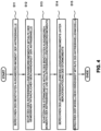
4 ein Ablaufdiagramm, das ein Berechnungsverfahren der Modellgeschwindigkeit bei einem Verfahren zum Reduzieren einer Antriebswellenvibration des umweltfreundlichen Fahrzeugs gemäß einer Ausführungsform der vorliegenden Offenbarung veranschaulicht; -
5 ein Diagramm, das eine Konfiguration eines Steuersystems zum Reduzieren einer Antriebswellenvibration in einem umweltfreundlichen Fahrzeug veranschaulicht, das in der Lage ist, ein Modellgeschwindigkeitsberechnungsschma gemäß einer anderen Ausführungsform der vorliegenden Offenbarung auszuwählen; -
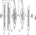
6 ein Ablaufdiagramm, das ein Verfahren zum Auswählen eines Modellgeschwindigkeitsberechnungsschemas und einer Modellgeschwindigkeit gemäß einer Schaltstufe gemäß einer anderen Ausführungsform der vorliegenden Offenbarung zeigt; -
7 ein Ablaufdiagramm, das ein Verfahren zum Auswählen eines Modellgeschwindigkeitsberechnungsschemas und einer Modellgeschwindigkeit gemäß einer Fahrzeuggeschwindigkeit, einem Wert eines Gaspedalpositionssensors (APS), und einem Wert eines Bremspedalsensors (BPS) gemäß einer anderen Ausführungsform der vorliegenden Offenbarung darstellt; und -
8 und9 Diagramme, die ein Verfahren veranschaulichen zum Berechnen eines Startwertes einer Modellgeschwindigkeit zum Zeitpunkt des Wechsels zu einem Radgeschwindigkeits-basierten Modellgeschwindigkeitsberechnungsschma gemäß den Fahrzeugzustandsinformationen wie beispielsweise einer Fahrzeuggeschwindigkeit, einem Wert eines GPPS und einem Wert eines BPS gemäß einer anderen Ausführungsform in der vorliegenden Offenbarung.
-
1 12 is a block diagram showing a system configuration of an electric vehicle (EV) according to the related art; -
2 a block diagram showing a system configuration of a hybrid electric vehicle (HEV) illustrated according to the related art; -
3 12 is a diagram illustrating a control system for reducing drive shaft vibration of an eco-friendly vehicle according to an embodiment of the present disclosure; -
4 12 is a flowchart illustrating a model speed calculation method in a method for reducing drive shaft vibration of the eco-friendly vehicle according to an embodiment of the present disclosure; -
5 12 is a diagram illustrating a configuration of a control system for reducing drive shaft vibration in an eco-friendly vehicle capable of selecting a model speed calculation scheme according to another embodiment of the present disclosure; -
6 14 is a flowchart showing a method for selecting a model speed calculation scheme and a model speed according to a shift stage according to another embodiment of the present disclosure; -
7 14 is a flow chart illustrating a method for selecting a model speed calculation scheme and a model speed according to a vehicle speed, an accelerator pedal position sensor (APS) value, and a brake pedal sensor (BPS) value according to another embodiment of the present disclosure; and -
8th and9 Diagrams illustrating a method of calculating a starting value of a model speed at the time of switching to a wheel speed-based model speed calculation scheme according to the vehicle state information such as a vehicle speed, a value of a GPPS, and a value of a BPS according to another embodiment in the present disclosure.
Es sei darauf hingewiesen, dass die beigefügten Zeichnungen nicht notwendigerweise maßstabsgetreu sind und eine vereinfachte Wiedergabe verschiedener bevorzugter Merkmale zeigen, welche die Grundprinzipien der Erfindung wiedergeben. Die spezifischen Ausgestaltungsmerkmale der vorliegenden Erfindung wie hierin offenbart, beinhaltend beispielsweise spezifische Abmessungen, Ausrichtungen, Positionen und Formen, werden teilweise insbesondere durch die vorgesehene Anwendung und Anwendungsumgebung bestimmt.It should be noted that the accompanying drawings are not necessarily to scale, presenting a simplified representation of various preferred features that reflect the basic principles of the invention. The specific design features of the present invention as disclosed herein, including, for example, specific dimensions, orientations, locations, and shapes will be determined in part particularly by the intended application and use environment.
In den Figuren beziehen sich Bezugszeichen auf gleiche oder gleichwertige Teile der vorliegenden Erfindung in den verschiedenen Figuren der Zeichnungen.In the figures, reference numbers refer to the same or equivalent parts of the present invention in the different figures of the drawings.
DETAILLIERTE BESCHREIBUNGDETAILED DESCRIPTION
Nachfolgend wir genauer Bezug genommen auf verschiedene Ausführungsformen, deren Beispiele in den beigefügten Zeichnungen dargestellt sind und untenstehend beschrieben werden. Obgleich die Erfindung im Zusammenhang mit beispielhaften Ausführungsformen beschrieben werden wird, sei angemerkt, dass die vorliegende Beschreibung die Erfindung nicht auf diese beispielhaften Ausführungsformen beschränkt.In the following, reference will be made in more detail to various embodiments, examples of which are illustrated in the accompanying drawings and described below. Although the invention will be described in connection with exemplary embodiments, it should be understood that present description does not limit the invention to those exemplary embodiments.
Die vorliegende Offenbarung betrifft ein Verfahren zur Reduzierung einer Antriebswellenvibration eines umweltfreundlichen Fahrzeugs, bei dem von einer Antriebswelle erzeugte Vibrationen unter Verwendung eines Motors, der mechanisch mit der Antriebswelle verbunden ist, reduziert werden. Insbesondere stellt die vorliegende Offenbarung ein verbessertes Verfahren zum Berechnen einer Modellgeschwindigkeit bereit, derart, dass eine genaue Vibrationskomponente extrahiert werden kann.The present disclosure relates to a method for reducing drive shaft vibration of an eco-friendly vehicle, in which vibration generated from a drive shaft is reduced using a motor mechanically connected to the drive shaft. In particular, the present disclosure provides an improved method for calculating a model velocity such that an accurate vibration component can be extracted.
Wie obenstehend beschrieben wurde, muss eine Vibrationskomponente der Antriebswelle extrahiert werden, um von der Antriebswelle ausgehende Vibrationen zu verringern. Die Vibrationsreduktionsleistung variiert gemäß der Genauigkeit der Extrahierung der Vibrationskomponente, weshalb es wichtig ist, die Vibrationskomponente genau zu extrahieren.As described above, in order to reduce vibration from the drive shaft, a vibration component of the drive shaft needs to be extracted. The vibration reduction performance varies according to the accuracy of extracting the vibration component, so it is important to accurately extract the vibration component.
Die Vibrationskomponente der Antriebswelle wird wie untenstehend extrahiert. Ein Idealmodell für die Antriebswelle, d.h. ein Berechnungsmodell, das in der Lage ist, eine Idealgeschwindigkeit (Modellgeschwindigkeit) der Antriebswelle zu berechnen, das keine Vibration berücksichtigt, wird entworfen. Eine der Geschwindigkeit der Antriebswelle entsprechende Modellgeschwindigkeit unter Ausschluss der Vibrationskomponente wird berechnet mithilfe des Berechnungsmodells, wodurch die Vibrationskomponente extrahiert wird mithilfe einer Differenz zwischen der errechneten Modellgeschwindigkeit und einer tatsächlichen Geschwindigkeit, die einer tatsächlichen Geschwindigkeit einer Antriebswelle entspricht.The vibration component of the drive shaft is extracted as below. An ideal model for the drive shaft, that is, a calculation model capable of calculating an ideal speed (model speed) of the drive shaft that does not take vibration into account is designed. A model speed corresponding to the drive shaft speed excluding the vibration component is calculated using the calculation model, whereby the vibration component is extracted using a difference between the calculated model speed and an actual speed corresponding to an actual speed of a drive shaft.
Wenn die Modellgeschwindigkeit genau als die Idealgeschwindigkeit der Antriebswelle unter Ausschluss der Vibrationskomponente berechnet wird, kann durch Berechnen der Differenz zwischen den beiden Geschwindigkeiten eine genaue Vibrationskomponente extrahiert werden. Jedoch enthält die berechnete Modellgeschwindigkeit verglichen mit der Idealgeschwindigkeit unter Ausschluss der Vibrationskomponente eine Fehlerkomponente.If the model speed is accurately calculated as the ideal drive shaft speed excluding the vibration component, then by calculating the difference between the two speeds, accurate vibra tion component are extracted. However, the calculated model speed contains an error component compared to the ideal speed excluding the vibration component.
Um den Fehler zu eliminieren, wird die Differenz zwischen der Modellgeschwindigkeit und der tatsächlichen Geschwindigkeit (tatsächliche Geschwindigkeit der Antriebswelle) erhalten, und dann die Fehlerbehebungssteuerung unter Benutzung eines Hochpassfilters (HPF) etc. angewendet. Eine angemessene Ordnung einer Fehlerbeseitigungssteuerung muss auf Grundlage einer Form (Ordnung) der Fehlerkomponente ermittelt werden.In order to eliminate the error, the difference between the model speed and the actual speed (actual speed of the drive shaft) is obtained, and then error recovery control using a high-pass filter (HPF), etc. is applied. An appropriate order of error recovery control needs to be determined based on a form (order) of the error component.
Im Allgemeinen nimmt die Ordnung der Fehlerbeseitigungssteuerung proportional zu der Ordnung der Fehlerkomponente zu, und ein Auftreten einer Phasenverzögerung nimmt zu, da die Ordnung der Fehlerbeseitigungssteuerung zunimmt. Daher kann eine verschiedene Vibrationskomponente von der aktuellen Vibration extrahiert werden.In general, the order of the debugging control increases in proportion to the order of the error component, and an occurrence of phase lag increases as the order of the debugging control increases. Therefore, a different vibration component can be extracted from the actual vibration.
Das bedeutet, dass eine genaue Vibrationskomponente extrahiert werden kann, wenn die Ordnung der Fehlerkomponente minimiert wird. Die Modellgeschwindigkeit muss berechnet werden, um ein Wert zu sein, der so nahe wie möglich an der Idealgeschwindigkeit der Antriebswelle liegt, unter Ausschluss der Vibrationskomponente, um die Ordnung der Fehlerbehebungssteuerung beinhaltend den Filter, etc. zu reduzieren.This means that an accurate vibration component can be extracted when the order of the error component is minimized. The model speed needs to be calculated to be a value as close as possible to the ideal drive shaft speed excluding the vibration component in order to reduce the order of the debugging control including the filter, etc.
In dieser Hinsicht kann ein auf ein Fahrzeug wirkendes Störmoment mithilfe einer Störungsbeobachtungsvorrichtung beachtet werden, wenn die Modellgeschwindigkeit berechnet wird, und das Störmoment kann ausgeglichen werden, wenn die Modellgeschwindigkeit berechnet wird, wodurch die Ordnung einer in der Modellgeschwindigkeit enthaltenen Fehlerkomponente minimiert wird. Auf diese Weise kann die Genauigkeit der Extrahierung der Vibrationskomponente verbessert werden.In this regard, a disturbance torque acting on a vehicle can be observed using a disturbance observer when the model speed is calculated, and the disturbance torque can be canceled when the model speed is calculated, thereby minimizing the order of an error component included in the model speed. In this way, the accuracy of extracting the vibration component can be improved.
Die vorliegende Offenbarung kann sowohl bei dem reinen Elektrofahrzeug (EV) mit der in
Die Antriebswelle ist eine Welle, von der ein Drehmoment des Antriebsmotors 13 in die Systeme aus den
Daher kann in der untenstehenden Beschreibung eine Geschwindigkeit der Antriebswelle durch eine Geschwindigkeit des Motors ersetzt werden, und ein Modell der Antriebswelle kann durch ein Modell des Motors ersetzt werden.Therefore, in the description below, a speed of the drive shaft can be replaced with a speed of the motor, and a model of the drive shaft can be replaced with a model of the motor.
Die vorliegende Offenbarung wird nun untenstehend in Bezugnahme auf
Das in
In Bezugnahme auf
Der Motordrehmomentanweisungswert T1 kann ein von einer Fahrzeugsteuereinheit (FSE) oder einer Hybridsteuereinheit (HSE-nicht dargestellt) an das Motorsteuergerät 17 gelieferter Anweisungswert sein.The engine torque command value T 1 may be a command value provided to the
Zusätzlich steuert in der vorliegenden Erfindung das Motorsteuergerät 17 eine Drehmomentausgabe des Antriebsmotors 13 mithilfe eines finalen Drehmomentanweisungswerts T1' der berechnet wird, um den Motordrehmomentanweisungswert T1 durch das Vibrationsreduzierungs-Ausgleichsdrehmoment Tvib auszugleichen, so dass eine von der Antriebswelle erzeugte Vibration verringert werden kann.In addition, in the present invention, the
Das Drehmoment T1' wird von dem Antriebsmotor 13 gemäß einer Drehmomentanweisung ausgegeben, welche durch das Vibrationsreduzierungs-Ausgleichsdrehmoment Tvib ausgeglichen wird, weshalb T1' ein tatsächliches Ausgabedrehmoment von dem Antriebsmotor sein kann.The torque T 1 ' is output from the driving
Zudem sind T2 und T3 Drehmomentwerte, die für den Motor 11 und den Starter-Generator (zweiter Motor direkt mit dem Motor verbunden) (MG2) 15 benötigt werden, und können Drehmomentausgabewerte des Motors 11 und des Starter-Generators 15 sein, die gemäß deren Anweisungswerten gesteuert werden.In addition, T 2 and T 3 are torque values required for the
Jedoch sind in dem Elektrofahrzeug der Motor 11 und der Starter-Generator 15 nicht vorhanden, weshalb sowohl T2 als auch T3 jeweils 0 werden.However, in the electric vehicle, the
Zudem ist Tbrake ein Drehmomentwert, der für eine Bremse benötigt wird, und Tload ist ein Fahrzeuglastdrehmoment, das durch einen Neigungswinkel einer Straße, auf der das Fahrzeug gefahren wird, erzeugt wird. Tload ist ein Drehmomentwert, der aus dem Neigungswinkel und einem Gewicht des Fahrzeugs berechnet werden kann.In addition, T brake is a torque value required for a brake, and T load is a vehicle load torque generated by an inclination angle of a road on which the vehicle is driven. T load is a torque value that can be calculated from the lean angle and a weight of the vehicle.
In Bezugnahme auf
In Bezugnahme auf ![]()
![]()
In Bezugnahme auf
In Bezugnahme auf
Hierbei sind mit Ausnahme des Störmoments d alle der oben beschriebenen an der Antriebswelle bereitgestellten Drehmomente bekannte Werte. Daher kann eine Modellgeschwindigkeit ωm genau berechnet werden, wenn ein Schätzwert d' des Störmoments so nahe wie möglich an dem tatsächlichen Störmoment d erhalten werden kann.With the exception of the disturbance torque d, all of the torques provided on the drive shaft described above are known values. Therefore, a model speed ω m can be calculated accurately if an estimated value d' of the disturbance torque as close as possible to the actual disturbance torque d can be obtained.
Die tatsächliche Antriebswellengeschwindigkeit ω wird durch einen Sensor etc. gemessen und erhalten und wird als Variable in einem Verfahren zur Berechnung der Modellgeschwindigkeit ωm und einem Verfahren zum Extrahieren einer Vibrationskomponente ωvib verwendet.The actual driving shaft speed ω is measured and obtained by a sensor, etc., and is used as a variable in a method of calculating the model speed ω m and a method of extracting a vibration component ω vib .
Das Vibrationsreduzierungs-Ausgleichsdrehmoment Tvib zum Reduzieren der von einer Antriebswelle erzeugten Vibration kann erhalten werden durch ein Verfahren zum Berechnen der Modellgeschwindigkeit ωm, ein Verfahren zum Extrahieren der Vibrationskomponente ωvib mithilfe eines Hochpassfilters HPF oder eines Bandpassfilters (BPF) aus einer Differenz Δω zwischen der berechneten Modellgeschwindigkeit ωm und der gemessenen tatsächlichen Geschwindigkeit ω, und ein Verfahren zum Berechnen des Vibrationsreduzierungs-Ausgleichsdrehmoments Tvib basierend auf der extrahierten Vibrationskomponente ωvib und Fahrzustandsinformationen wie etwa einem Fahrmodus, einer Schaltstufe, etc. des Fahrzeugs.The vibration reduction compensation torque T vib for reducing the vibration generated by a drive shaft can be obtained by a method of calculating the model speed ω m , a method of extracting the vibration component ω vib using a high-pass filter HPF or a band-pass filter (BPF) from a difference Δω between the calculated model speed ω m and the measured actual speed ω, and a method of calculating the vibration reduction compensation torque T vib based on the extracted vibration component ω vib and driving condition information such as a driving mode, a gear stage, etc. of the vehicle.
Hierbei wird die Modellgeschwindigkeit ωm berechnet durch einen Antriebswellenmodellgeschwindigkeitsberechner 200 basierend auf einer Drehmomentkomponenteneingabe an die Antriebswelle des Fahrzeugs. Wie in
Das benötigte Ausgabedrehmoment der Antriebswelle Tnet' kann berechnet werden durch einen Berechner für das benötigte Ausgabedrehmoment der Antriebswelle 210, der die Drehmomente T1, T2, T3, und Tbrake, die für den Antriebsmotor 13, den Motor 11, den Starter-Generator 15, und die Bremse (nicht dargestellt) benötigt werden, und ein Fahrzeuglastdrehmoment Tload als Eingaben aufnimmt (S11), und kann erhalten werden Subtrahieren des Fahrzeuglastdrehmoments Tload von den Drehmomenten, die für die Drehmomentquellen des Fahrzeugs benötigt werden, welche Drehmomente auf die Antriebswelle aufbringen.The required output shaft torque T net ' can be calculated by a required output
Die Drehmomentquellen des Fahrzeugs können dem Antriebsmotor 13, dem Motor 11, dem Starter-Generator 15, und der Bremse entsprechen. Hierbei ist das für die Bremse benötigte Drehmoment Tbrake ähnlich dem Lastdrehmoment Tload ein negatives Drehmoment. Somit kann das benötigte Ausgabedrehmoment der Antriebswelle Tnet' nach der folgenden Gleichung berechnet werden:![]()
![]()
Hierbei kann das für den Antriebsmotor 13 benötigte Drehmoment T1 einem Drehmomentanweisungswert für den Antriebsmotor entsprechen und alle Drehmomente T2, T3, und Tbrake, die für den Motor 11, den Starter-Generator 15, und die Bremse benötigt werden, entsprechen Drehmomentwerten, die in Drehmomente der Welle des Antriebsmotors (MG1) gewandelt wurden.Here, torque T 1 required for
In diesem Moment können die für den Motor 11 und den Starter-Generator 15 benötigten Drehmomente T2 und T3 Werten entsprechen, die erhalten werden durch Umwandeln von Werten einer Motordrehmomentanweisung und einer Starter-Generator Drehmomentanweisung in Drehmomente der Welle des Antriebsmotors (MG1), und das für die Bremse benötigte Drehmoment Tbrake kann einem umgewandelten Wert eines Bremsmoments entsprechen, das von einer Bremse eines Antriebsrads erzeugt wird.At this moment, the torques T 2 and T 3 required for the
Als nächstes wird das Antriebswelleneingabedrehmoment Tacc' unter Verwendung der gemessenen tatsächlichen Geschwindigkeit ω der Antriebswelle (S12) von einer Antriebswelleneingabedrehmoment-Abschätzeinheit 220 aus
Wie oben erläutert, dreht sich die Antriebswelle mit der Geschwindigkeit ω, wenn das tatsächliche Antriebswellendrehmoment Tacc auf die Antriebswelle aufgebracht wird. Wenn eine Transferfunktion in der Antriebswelle 100 als G(s) bezeichnet wird, können die tatsächliche Geschwindigkeit der Antriebswelle ω und das Antriebswelleneingabedrehmoment Tacc durch die folgenden Gleichungen ausgedrückt werden:![]()
![]()
![]()
![]()
In der obigen Gleichung (4) ist G(s) die Transferfunktion in der tatsächlichen Antriebswelle 100. Wenn eine Transferfunktion eines idealen Antriebswellenmodells, welches die tatsächliche Antriebswelle 100 als Modell darstellt, das bedeutet, das Antriebswellenmodell 241 mit dem die ideale Modellgeschwindigkeit ωm unter Vernachlässigung der Vibration berechnet werden soll, als Gm(s) bezeichnet wird, kann somit das Antriebswelleneingabedrehmoment Tacc' unter Verwendung von Gm(s) anstelle von G(s) in Gleichung 4 geschätzt werden.In the above equation (4), G(s) is the transfer function in the
In der Annahme, dass die Antriebswelle ein starrer Körper ist und ein geschätzter Wert des Antriebswelleneingabedrehmoments als Tacc' bezeichnet wird, kann der geschätzte Wert des Antriebswelleneingabedrehmoments durch die folgende Gleichung ausgedrückt werden:![]()
![]()
In Gleichung (5) bezeichnet Jm ein Trägheitsmoment der Antriebswelle, die ein starrer Körper ist.In Equation (5), J m denotes a moment of inertia of the drive shaft, which is a rigid body.
In Bezugnahme auf Gleichung (5) ist die Transferfunktion Gm(s) zum Berechnen des geschätzten Werts des Antriebswelleneingabedrehmoments Tacc', das auf die Antriebswelle aufgebracht wird, aus der tatsächlichen Geschwindigkeit der Antriebswelle ω ein System, bei dem eine Ordnung des Zählers größer ist als eine Ordnung des Nenners. Daher wird die Transferfunktion Gm(s) aus mathematischer Sicht durch Differenzieren (Engl. differentiate: Differenzieren bzw. ggf. Dividieren) der tatsächlichen Antriebswellengeschwindigkeit und Multiplizieren mit dem Trägheitsmoment berechnet, und ist daher gegenüber einer Rauschkomponente der tatsächlichen Geschwindigkeit der Antriebswelle anfällig.Referring to equation (5), the transfer function G m (s) for calculating the estimated value of the drive shaft input torque T acc ' applied to the drive shaft from the actual speed of the drive shaft ω is a system in which an order of the numerator is larger is as an order of the denominator. Therefore, from a mathematical point of view, the transfer function G m (s) is calculated by differentiating the actual drive shaft speed and multiplying it by the moment of inertia, and is therefore vulnerable to a noise component of the actual drive shaft speed.
In dieser Hinsicht können der Nenner und der Zähler unter Verwendung des Filters Q die gleiche Ordnung besitzen. Wenn ein primärer Tiefpassfilter LPF in der vorliegenden Ausführungsform eingesetzt wird, kann das Antriebswelleneingabedrehmoment Tacc' wie aus der folgenden Gleichung abgeschätzt werden:![]()
![]()
Q(s) ist eine Transferfunktion des LPF, und eine Zeitkonstante τ des LPF Q ist größer als eine Frequenz einer Vibrationskomponente, derart, dass ein durch die Vibrationskomponente geschätztes Drehmoment ausgeschlossen werden kann.Q(s) is a transfer function of the LPF, and a time constant τ of the LPF Q is larger than a frequency of a vibration component, so that a torque estimated by the vibration component can be excluded.
Die Transferfunktion Q(s) des Filters wird derart eingestellt, dass eine Ordnung des Zählers zu jeder Zeit kleiner oder gleich einer Ordnung des Nenners in Q(s)/Gm(s) ist, und der Filter wird zusätzlich derart angewendet, dass eine Ordnung des Zählers konstant kleiner oder gleich einer Ordnung des Nenners ist in der Transferfunktion Q(s)/Gm(s) zum Berechnen des geschätzten Werts des Antriebswelleneingabedrehmoments Tacc' aus der tatsächlichen Geschwindigkeit der Antriebswelle ω, wodurch eine gewisse Robustheit gegenüber der Rauschkomponente sichergestellt wird.The transfer function Q(s) of the filter is adjusted such that an order of the numerator is less than or equal to an order of the denominator in Q(s)/G m (s) at all times, and the filter is additionally applied such that a Order of the numerator is constantly less than or equal to an order of the denominator in the transfer function Q(s)/G m (s) for calculating the estimated value of the driveshaft input torque T acc ' from the actual speed of the driveshaft ω, thereby providing some robustness to the noise component is ensured.
Als nächstes wird der geschätzte Wert d' des Störmoments von einer Störmoment-Abschätzeinheit 230 berechnet, die das benötigte Ausgabedrehmoment der Antriebswelle Tnet' und das Antriebswelleneingabedrehmoment Tacc' als Eingabewerte aufnimmt und kann berechnet werden als Differenz zwischen dem benötigten Ausgabedrehmoment der Antriebswelle Tnet', welches von der Berechnungseinheit 210 für das benötigte Ausgabedrehmoment der Antriebswelle berechnet wird, und dem Antriebswelleneingabedrehmoment Tacc', welches von der Antriebswelleneingabedrehmoment-Abschätzeinheit 220 berechnet wird.Next, the estimated value d' of the disturbance torque is calculated by a disturbance
In diesem Moment wird der gleiche Filter Q wie derjenige Filter, der verwendet wird, wenn das Antriebswelleneingabedrehmoment abgeschätzt wird, auf das benötigte Ausgabedrehmoment der Antriebswelle Tnet' angewendet, welches von der Berechnungseinheit 210 für das benötige Ausgabedrehmoment der Antriebswelle ausgegeben wird, derart, dass eine Phasenverzögerung und eine Betragsänderung, die von dem Filter auftreten, auf ähnliche Weise von dem benötigten Ausgabedrehmoment der Antriebswelle auftreten, und der geschätzte Wert d' des Störmoments berechnet wird unter Verwendung des benötigten Ausgabedrehmoments der Antriebswelle, welches einer Tiefpassfilterung durch den Filter Q unterzogen wird.At this moment, the same filter Q as the filter used when estimating the drive shaft input torque is applied to the required drive shaft output torque T net ', which is output from the required drive shaft output
Wenn der primäre LPF verwendet wird, kann das Störmoment d' gemäß der folgenden Gleichung abgeschätzt werden: ![]()
![]()
Wenn das Störmoment d' wie oben angegeben abgeschätzt wird, wird das Antriebswellenmodelleingabedrehmoment Tm zum Berechnen der Modellgeschwindigkeit unter Verwendung des geschätzten Störmoments d' und dem benötigten Ausgabedrehmoment der Antriebswelle Tnet' berechnet, wobei letzteres von der Berechnungseinheit 210 für das benötigte Ausgabedrehmoment der Antriebswelle berechnet wird. In diesem Moment kann eine Gleichung zur Berechnung des Antriebswellenmodelldrehmoments Tm zur Berechnung der Modellgeschwindigkeit durch die folgende Gleichung ausgedrückt werden:![]()
![]()
Wie oben beschrieben, wenn das Antriebswellenmodelleingabedrehmoment Tm berechnet wird, wird die Modellgeschwindigkeit ωm durch eine Geschwindigkeitsberechnungseinheit 240 berechnet, welche das Antriebswellenmodelleingabedrehmoment Tm als Eingabewert aufnimmt. In diesem Moment kann die Modellgeschwindigkeit ωm durch eine untenstehende Gleichung aus dem Antriebswellenmodelleingabedrehmoment Tm unter Verwendung der Transferfunktion Gm(s) des Antriebswellenmodells 241 berechnet werden:![]()
![]()
Wenn die Modellgeschwindigkeit ωm wie oben beschrieben berechnet wird, erhält eine Vibrationskomponentenberechnungseinheit 300 eine Vibrationskomponente basierend auf einer Abweichung Δ ω zwischen der Modellgeschwindigkeit ωm und der tatsächlichen Geschwindigkeit ω. In diesem Moment kann die Vibrationskomponente ωvib berechnet werden durch Anwenden einer Fehlerbeseitigungssteuerung wie etwa dem Hochpassfilter HPF, etc. auf die Differenz Δω zwischen der Modellgeschwindigkeit ωm und der tatsächlichen Geschwindigkeit ω.When the model speed ω m is calculated as described above, a vibration
Nachdem die Vibrationskomponente ωvib erhalten wurde, berechnet eine Berechnungseinheit 400 für das Vibrationsreduzierungs-Ausgleichsdrehmoment das Vibrationsreduzierungs-Ausgleichsdrehmoment Tvib basierend auf der extrahierten Vibrationskomponente ωvib und Fahrzustandsinformationen wie etwa einem Fahrtmodus, einer Gangstufe, etc., des Fahrzeugs.After the vibration component ω vib is obtained, a vibration reduction compensation
Die Vibrationskomponente ωvib unter Verwendung der Modellgeschwindigkeit ωm und der tatsächlichen Geschwindigkeit ω und dem Vibrationsreduzierungs-Ausgleichsdrehmoment Tvib basierend auf der berechneten Vibrationskomponente ωvib und den Fahrzustandsinformationen des Fahrzeugs kann unter Verwendung des herkömmlichen Verfahrens berechnet werden.The vibration component ω vib using the model speed ω m and the actual speed ω and the vibration reduction compensation torque T vib based on the calculated vibration component ω vib and the vehicle running state information can be calculated using the conventional method.
Wenn das Vibrationsreduzierungs-Ausgleichsdrehmoment Tvib wie oben beschrieben erhalten wird, gleicht das Motorsteuergerät MCU 17 den Drehmomentanweisungswert T1 für den Antriebsmotor 13 durch das Vibrationsreduzierungs-Ausgleichsdrehmoment Tvib aus und steuert eine Drehmomentausgabe des Antriebsmotors 13 gemäß des ausgeglichenen finalen Drehmomentanweisungswerts T1'.When the vibration reduction compensation torque T vib is obtained as described above, the
Gemäß einer anderen Ausführungsform kann eine Vielzahl von Modellgeschwindigkeitsberechnungsschemata angewendet werden, und eines aus der Vielzahl von Modellgeschwindigkeitsberechnungsschemata kann auf Grundlage von Fahrzeugzustandsinformationen ausgewählt werden.According to another embodiment, a plurality of model speed calculation schemes may be applied, and one of the plurality of model speed calculation schemes may be selected based on vehicle state information.
Ein Verfahren zum Auswählen eines Modellgeschwindigkeitsberechnungsschemas wird zusätzlich bereitgestellt, derart, dass ein Vorteil jedes Modellgeschwindigkeitsberechnungsschemas gemäß einem Fahrzeugzustand angewendet werden kann.
Die Ausführungsform aus
Zusätzlich ist das andere der beiden Modellgeschwindigkeitsberechnungsschemata ein herkömmliches Modellgeschwindigkeitsberechnungsschema.In addition, the other of the two model speed calculation schemes is a conventional model speed calculation scheme.
Das Modellgeschwindigkeitsberechnungsschema gemäß der Ausführungsform der
Zudem ist das herkömmliche Modellgeschwindigkeitsberechnungsschema ein Schema zur Berechnung einer Modellgeschwindigkeit ωm' unter Verwendung einer Radgeschwindigkeit. Die Radgeschwindigkeit ist eine Komponente, die erzeugt wird, wenn eine Vibration der Antriebswelle abgeschwächt wird. Somit, wenn die Radgeschwindigkeit verwendet wird, kann eine genaue Modellgeschwindigkeit berechnet werden. Zudem wird die Modellgeschwindigkeit nur mithilfe von Signalverarbeitung für die Radgeschwindigkeit berechnet, weshalb ein Lastfaktor gering ist.In addition, the conventional model speed calculation scheme is a scheme for calculating a model speed ω m ' using a wheel speed. The wheel speed is a component generated when vibration of the drive shaft is attenuated. Thus, when wheel speed is used, an accurate model speed can be calculated. In addition, the model speed is calculated only using signal processing for the wheel speed, therefore a load factor is small.
Deshalb erlaub die Ausführungsform aus
Zudem wird eine durch das drehmomentbasierte Modellgeschwindigkeitsberechnungsschema erhaltene Modellgeschwindigkeit ωm als eine drehmomentbasierte Modellgeschwindigkeit bezeichnet, und eine durch das radgeschwindigkeitsbasierte Modellgeschwindigkeitsberechnungsschema erhaltene Modellgeschwindigkeit ωm' wird als radgeschwindigkeitsbasierte Modellgeschwindigkeit bezeichnet.In addition, a model speed ω m obtained by the torque-based model speed calculation scheme is referred to as a torque-based model speed, and a model speed ω m ' obtained by the wheel speed-based model speed calculation scheme is referred to as a wheel speed-based model speed.
In Bezugnahme auf
Das Bezugszeichen 202 bezeichnet eine Modellgeschwindigkeitsauswahleinheit, die ein Modellgeschwindigkeitsberechnungsschema auswählt und wechselt und eine Modellgeschwindigkeit ausgibt, die gemäß dem ausgewählten Modellgeschwindigkeitsberechnungsschema in der untenstehenden Beschreibung berechnet wurde.
Zunächst können Fahrzeugzustandsinformationen einer Gangstufe eines Getriebes in einem Fahrzeug beinhaltend dem Getriebe entsprechen, und ein Modellgeschwindigkeitsberechnungsschema wird gemäß der Gangstufe ausgewählt.First, vehicle state information may correspond to a gear ratio of a transmission in a vehicle including the transmission, and a model speed calculation scheme is selected according to the gear ratio.
In einem niedrigen Gang, der kleiner oder gleich einem eingestellten Gang ist, ist ein Übersetzungsverhältnis der Antriebswelle zu einem Rad groß, und daher kann eine Verzögerungskomponente einer Radgeschwindigkeit aus Sicht der Antriebswelle groß sein. Deshalb wird vorteilhafterweise die drehmomentbasierte Modellgeschwindigkeit ωm verwendet. Im Gegensatz dazu wird in einer hohen Gangstufe , die größer ist als der eingestellte Gang, die radgeschwindigkeitsbasierte Modellgeschwindigkeit ωm'vorteilhafterweise verwendet.In a low gear that is less than or equal to a set gear, a gear ratio of the drive shaft to a wheel is large, and therefore a deceleration component of a wheel speed viewed from the drive shaft may be large. Therefore, the torque-based model speed ω m is advantageously used. In contrast, in a high gear that is greater than the set Gear using wheel speed based model speed ω m 'advantageously.
Wenn der Gang geschaltet wird, das heißt wenn eine Gangschaltung als gestartet bestimmt wird, wird ein nach dem Gangschalten zu verwendendes Modellgeschwindigkeitsberechnungsschema auf Grundlage einer Zielgangstufe des Gangschaltens in S22 bestimmt.When the gear is shifted, that is, when a gear shift is determined to be started, a model speed calculation scheme to be used after the gear shift is determined based on a target gear stage of the gear shift in S22.
Wenn das Modellgeschwindigkeitsberechnungsschema gemäß der Zielgangstufe bestimmt wurde, wird bestimmt, ob ein gegenwärtig verwendetes Modellgeschwindigkeitsberechnungsschema gewechselt werden muss, indem das bestimmte Modellgeschwindigkeitsberechnungsschema nach einem Gangschalten mit dem gegenwärtig verwendeten Modellgeschwindigkeitsberechnungsschema in S23 verglichen wird.When the model speed calculation scheme has been determined according to the target gear stage, it is determined whether a currently used model speed calculation scheme needs to be changed by comparing the determined model speed calculation scheme after a gear shift with the currently used model speed calculation scheme in S23.
Wenn das Modellgeschwindigkeitsberechnungsschema nach dem Gangschalten von dem gegenwärtigen Modellgeschwindigkeitsberechnungsschema verschieden ist, wird in S24 bestimmt, ob das Gangschalten tatsächlich abgeschlossen ist. Wenn der tatsächliche Abschluss des Gangschaltens von einem Signal einer Getriebesteuerung bestätigt wurde, wird das gegenwärtige Modellgeschwindigkeitsberechnungsschema zu dem neuen Modellgeschwindigkeitsberechnungsschema gewechselt, das gemäß der Zielgangstufe in S25 bestimmt wird.When the model speed calculation scheme after the gear shift is different from the current model speed calculation scheme, it is determined in S24 whether the gear shift is actually completed. When the actual completion of gear shifting has been confirmed by a signal from a transmission controller, the current model speed calculation scheme is switched to the new model speed calculation scheme determined according to the target gear ratio in S25.
Wenn hierbei ein Modellgeschwindigkeitsberechnungsschema gewechselt wird von dem radgeschwindigkeitsbasierten Modellgeschwindigkeitsberechnungsschema hin zu dem drehmomentbasierten Modellgeschwindigkeitsberechnungsschema, wird eine tatsächliche Geschwindigkeit der Antriebswelle ω zum Zeitpunkt des Wechsels als Ausgangswert für die Modellgeschwindigkeitsberechnung (Anfangsmodellgeschwindigkeit ωm) verwendet.Here, when a model speed calculation scheme is changed from the wheel speed-based model speed calculation scheme to the torque-based model speed calculation scheme, an actual drive shaft speed ω at the time of change is used as an initial value for the model speed calculation (initial model speed ω m ).
Wenn ein Modellgeschwindigkeitsberechnungsschema von dem drehmomentbasierten Modellgeschwindigkeitsberechnungsschema hin zu dem radgeschwindigkeitsbasierten Modellgeschwindigkeitsberechnungsschema gewechselt wird, kann das Berechnungsschema unmittelbar unter Verwendung einer Radgeschwindigkeit zum Zeitpunkt des Wechsels gewechselt werden.When a model speed calculation scheme is switched from the torque-based model speed calculation scheme to the wheel speed-based model speed calculation scheme, the calculation scheme can be switched immediately using a wheel speed at the time of switching.
Mit anderen Worten wird eine Modellgeschwindigkeit ωm', die durch das gewechselte radgeschwindigkeitsbasierte Modellgeschwindigkeitsberechnungsschema berechnet wurde, unmittelbar als Modellgeschwindigkeitsanfangswert zum Zeitpunkt des Abschlusses des Gangschaltens verwendet. Da eine Vibrationsreduzierungs-Drehmomentausgleichsfunktion zum Zeitpunkt des Gangschaltens deaktiviert ist, wird die Funktion mit Abschluss des Gangschaltens initialisiert, und dann wird die Funktion reaktiviert, ist ein Anfangs- bzw. Ausgangswert einer Modellgeschwindigkeit zum Zeitpunkt des Wechselns des Berechnungsschemas nicht problematisch.In other words, a model speed ω m ' calculated by the switched wheel speed-based model speed calculation scheme is immediately used as a model speed initial value at the time of gear shift completion. Since a vibration reduction torque compensation function is disabled at the time of gear shifting, the function is initialized upon completion of gear shifting, and then the function is reactivated, an initial value of a model speed at the time of switching the calculation scheme is not problematic.
Als nächstes können eine Fahrzeuggeschwindigkeit und/oder ein Wert eines Gaspedalpositionssensors (APS) und/oder ein Wert eines Bremspedalsensors (BPS) einer Fahrzeugzustandsinformation entsprechen, die ein Modellgeschwindigkeitsberechnungsschema als ein auf ein Fahrzeug, das keine Getriebe beinhaltet, anwendbares Beispiel bestimmt.Next, a vehicle speed and/or an accelerator pedal position sensor (APS) value and/or a brake pedal sensor (BPS) value may correspond to vehicle state information that determines a model speed calculation scheme as an example applicable to a vehicle that does not include transmissions.
Wenn Fahrzeuggeschwindigkeitsinformationen verwendet werden, wird das drehmomentbasierte Modellgeschwindigkeitsberechnungsschema (drehmomentbasierte Modellgeschwindigkeit wird ausgewählt) unter der Bedingung einer geringen Geschwindigkeit verwendet, die geringer oder gleich einer vorgegebenen Bezugsfahrzeuggeschwindigkeit ist, und das radgeschwindigkeitsbasierte Modellgeschwindigkeitsberechnungsschema wird (radgeschwindigkeitsbasierte Modellgeschwindigkeit wird ausgewählt) unter der Bedingung einer hohen Geschwindigkeit, welche die Bezugsfahrzeuggeschwindigkeit übersteigt, verwendet.When vehicle speed information is used, the torque-based model speed calculation scheme is used (torque-based model speed is selected) under a low speed condition that is less than or equal to a predetermined reference vehicle speed, and the wheel speed-based model speed calculation scheme is used (wheel speed-based model speed is selected) under a high speed condition, which exceeds the reference vehicle speed is used.
Zudem ist der APS ein Sensor zum Detektieren eines Betätigungszustands eines Gaspedals, und der BPS ist ein Sensor zum Detektieren eines Betätigungszustands eines Bremspedals. Das Fahrzeug wird als in einem schnell beschleunigten Zustand bestimmt, wenn eine Änderungsrate (oder der Änderungsbetrag) eines Werts des APS größer oder gleich einem ersten Referenzwert ist, und wird als in einem schnell verzögerten Zustand bestimmt, wenn eine Änderungsrate (oder der Änderungsbetrag) eines Werts der BPS größer oder gleich einem zweiten Referenzwert ist.+In addition, the APS is a sensor for detecting an operation state of an accelerator pedal, and the BPS is a sensor for detecting an operation state of a brake pedal. The vehicle is determined to be in a rapidly accelerated state when a rate of change (or the change amount) of a value of the APS is greater than or equal to a first reference value, and is determined to be in a rapidly decelerating state when a rate of change (or the change amount) of a value of the BPS is greater than or equal to a second reference value.+
Wenn das Fahrzeug als in einem schnell beschleunigten/verzögerten Zustand basierend auf dem Wert des APS und dem Wert des BPS bestimmt wird, wird das drehmomentbasierte Modellgeschwindigkeitsberechnungsschema verwendet (drehmomentbasierte Modellgeschwindigkeit wird ausgewählt). Andernfalls wird das radgeschwindigkeitsbasierte Modellgeschwindigkeitsberechnungsschema verwendet (radgeschwindigkeitsbasierte Modellgeschwindigkeit wird ausgewählt).When the vehicle is determined to be in a rapidly accelerated/decelerated state based on the value of APS and the value of BPS, the torque-based model speed calculation scheme is used (torque-based model speed is selected). Otherwise, the wheel speed based model speed calculation scheme is used (wheel speed based model speed is selected).
Wenn ein Modellgeschwindigkeitsberechnungsschema basierend auf gegenwärtigen Fahrzeugzustandsinformationen wie etwa einer Fahrzeuggeschwindigkeit, einem Wert des APS, oder einem Wert der BPS wie oben beschrieben bestimmt wird, wird das bestimmte Modellgeschwindigkeitsberechnungsschema mit einem gegenwärtig verwendeten Modellgeschwindigkeitsberechnungsschema verglichen, um zu bestimmen, ob das Modellgeschwindigkeitsberechnungsschema gewechselt werden muss.When a model speed calculation scheme is determined based on current vehicle state information such as a vehicle speed, a value of APS, or a value of BPS as described above, the determined model speed calculation scheme is compared to a currently used model speed calculation scheme to determine whether the model speed calculation scheme needs to be changed.
Wenn das Modellgeschwindigkeitsberechnungsschema gewechselt werden muss, wird das Modellgeschwindigkeitsberechnungsschema hin zu einem neuen Modellgeschwindigkeitsberechnungsschema gewechselt, welches basierend auf den gegenwärtigen Fahrzeugzustandsinformationen in S23' bestimmt wurde.When the model speed calculation scheme needs to be changed, the model speed calculation scheme is changed to a new model speed calculation scheme determined based on the current vehicle state information in S23'.
Wenn das Modellgeschwindigkeitsberechnungsschema von dem radgeschwindigkeitsbasierten Modellgeschwindigkeitsberechnungsschema hin zu dem drehmomentbasierten Modellgeschwindigkeitsberechnungsschema gewechselt wird in einem Verfahren zum Wechseln eines Modellgeschwindigkeitsberechnungsschemas wie oben beschrieben (Verändern einer Modellgeschwindigkeit), wird ein radgeschwindigkeitsbasierter Modellgeschwindigkeitswert zum Zeitpunkt des Wechsels als Anfangswert einer drehmomentbasierten Modellgeschwindigkeit verwendet.When the model speed calculation scheme is switched from the wheel speed-based model speed calculation scheme to the torque-based model speed calculation scheme in a method for switching a model speed calculation scheme as described above (changing a model speed), a wheel speed-based model speed value at the time of switching is used as an initial value of a torque-based model speed.
Wenn das Modellgeschwindigkeitsberechnungsschema von dem drehmomentbasierten Modellgeschwindigkeitsberechnungsschema hin zu dem radgeschwindigkeitsbasierten Modellgeschwindigkeitsberechnungsschema gewechselt wird, wird ein Wert gemäß einer Radgeschwindigkeit bestimmt, weshalb ein Anfangspunkt nicht gesetzt werden kann. Deshalb kann ein unterbrochener Punkt einer Modellgeschwindigkeit zum Zeitpunkt des Wechsels erzeugt werden.When the model speed calculation scheme is switched from the torque-based model speed calculation scheme to the wheel speed-based model speed calculation scheme, a value is determined according to a wheel speed, and therefore an initial point cannot be set. Therefore, a broken point of a model speed can be generated at the time of switching.
Ein unterbrochener Punkt einer Modellgeschwindigkeit, der erzeugt wird, wenn die Vibrationsreduzierungs-Drehmomentausgleichsfunktion kontinuierlich aktiviert ist, ist ein Faktor, der die Vibrationskomponentenextraktionsleistung verschlechtert, weshalb ein Anfangspunkt einer radgeschwindigkeitsbasierten Modellgeschwindigkeit virtuell gesetzt werden muss, wenn ein Berechnungsschema gewechselt wird. Eine Gleichung zur Berechnung einer Modellgeschwindigkeit durch Setzen eines virtuellen Anfangspunkts ist nachfolgend angegeben:![]()
ωm'' ist eine Modellgeschwindigkeit, auf die ein virtueller Anfangspunkt angewendet wird, wenn ein Berechnungsschema gewechselt wird, und die Modellgeschwindigkeit ωm'' des virtuellen Anfangspunkts ist eine Modellgeschwindigkeit zum Zeitpunkt des Wechsels zu dem radgeschwindigkeitsbasierten Modellgeschwindigkeitsberechnungsschema.
ωm_init ist ein Differenzwert zwischen der drehmomentbasierten Modellgeschwindigkeit ωm und der radgeschwindigkeitsbasierten Modellgeschwindigkeit ωm' zum Zeitpunkt des Verwendens eines Anfangswerts (zum Zeitpunkt des Wechselns eines Berechnungsschemas), und ωm_offset ist ein Wert, der gesetzt wird, um von 0 bis ωm_init mit einer konstanten Steigung oder Muster zu variieren. Zum Beispiel kann ωm_offset unter Verwendung des in ![]()
ω m '' is a model speed to which a virtual start point is applied when a calculation scheme is switched, and the model speed ω m '' of the virtual start point is a model speed at the time of switching to the wheel speed-based model speed calculation scheme.
ω m_init is a difference value between the torque-based model speed ω m and the wheel speed-based model speed ω m ' at the time of using an initial value (at the time of changing a calculation scheme), and ω m_offset is a value set to from 0 to ω m_init to vary with a constant slope or pattern. For example, ω m_offset can be calculated using the in
In Bezugnahme auf
Wenn ein zu setzender Anfangswert ωm'' als Modellgeschwindigkeitswert des radgeschwindigkeitsbasierten Berechnungsschemas zum Zeitpunkt des Wechselns eines Berechnungsschemas bestimmt wird, ist es möglich, eine Modellgeschwindigkeit unter Ausschluss eines unterbrochenen Punkts wie in
Wie vorstehend erläutert, schlägt die vorliegende Offenbarung ein verbessertes Modellgeschwindigkeitsberechnungsschema vor, das in der Lage ist, eine genaue Vibrationskomponente zu extrahieren in einem Verfahren zum Reduzieren von Vibrationen, die von einer Antriebswelle eines umweltfreundlichen Fahrzeugs erzeugt werden.As explained above, the present disclosure proposes an improved model speed calculation scheme capable of extracting an accurate vibration component in a method for reducing vibrations generated from a drive shaft of an eco-friendly vehicle.
In der verwandten Technik wurde eine Modellgeschwindigkeit mithilfe einer Radgeschwindigkeit oder basierend auf einem Antriebswelleneingabedrehmoment mithilfe eines Antriebswellenmodells berechnet. Wenn die Modellgeschwindigkeit mithilfe der Radgeschwindigkeit berechnet wurde, ist eine Genauigkeit der Modellgeschwindigkeit hoch. Jedoch kann eine fehlerhafte Vibrationskomponente extrahiert werden, da eine Modellgeschwindigkeit verglichen mit einer tatsächlichen Geschwindigkeit zum Zeitpunkt einer Beschleunigung/Verzögerung eines Fahrzeugs verzögert ist. Wenn die Modellgeschwindigkeit basierend auf dem Antriebswelleneingabedrehmoment berechnet wird durch Gestalten des Antriebswellenmodells, ist die Modellgeschwindigkeit zum Zeitpunkt einer Beschleunigung/Verzögerung eines Fahrzeugs nicht verzögert. Jedoch ist die Genauigkeit der Modellgeschwindigkeit aufgrund einer Ungenauigkeit des Modells und einem Lastdrehmoment, etc., verschlechtert.In the related art, a model speed was calculated using a wheel speed or based on a drive shaft input torque using a drive shaft mo dell's charged. When the model speed is calculated using the wheel speed, an accuracy of the model speed is high. However, since a model speed is delayed compared to an actual speed at the time of acceleration/deceleration of a vehicle, an erroneous vibration component may be extracted. When the model speed is calculated based on the drive shaft input torque by designing the drive shaft model, the model speed at the time of acceleration/deceleration of a vehicle is not delayed. However, the accuracy of the model speed is deteriorated due to inaccuracy of the model and load torque, etc.
Auf der anderen Seite wird gemäß der vorliegenden Offenbarung ein Antriebswellenmodell entworfen und eine Modellgeschwindigkeit basierend auf einem Antriebswelleneingabedrehmoment berechnet, weshalb die Modellgeschwindigkeit zum Zeitpunkt der Beschleunigung/Verzögerung eines Fahrzeugs nicht verzögert ist. Zur gleichen Zeit wird ein an das Fahrzeug geliefertes Störmoment durch eine Störmomentbeachtungseinheit beobachtet und die Modellgeschwindigkeit wird basierend auf dem Störmoment berechnet, weshalb die Genauigkeit der Modellgeschwindigkeit verbessert werden kann. Deshalb ist es möglich, eine Vibrationskomponente genauer zu extrahieren.On the other hand, according to the present disclosure, a drive shaft model is designed and a model speed is calculated based on drive shaft input torque, therefore the model speed is not delayed at the time of acceleration/deceleration of a vehicle. At the same time, a disturbance torque supplied to the vehicle is observed by a disturbance torque observation unit, and the model speed is calculated based on the disturbance torque, therefore the accuracy of the model speed can be improved. Therefore, it is possible to more accurately extract a vibration component.
Gemäß einem Steuerverfahren zum Reduzieren einer Antriebswellenvibration eines umweltfreundlichen Fahrzeugs der vorliegenden Offenbarung wird ein Modellgeschwindigkeitsberechnungsschema derart verbessert, dass eine genaue Vibrationskomponente extrahiert werden kann, wodurch die von einer Antriebswelle erzeugten Vibrationen wirksam vermindert werden.According to a control method for reducing drive shaft vibration of an eco-friendly vehicle of the present disclosure, a model speed calculation scheme is improved such that an accurate vibration component can be extracted, thereby effectively reducing vibration generated from a drive shaft.
Zudem wird ein drehmomentbasiertes Modellgeschwindigkeitsberechnungsschema oder ein radgeschwindigkeitsbasiertes Modellgeschwindigkeitsberechnungsschema ausgewählt und verwendet, wenn eine Modellgeschwindigkeit berechnet wird, wodurch sich im Ergebnis die Vorteile beider Berechnungsschemata in Abhängigkeit eines Fahrzeugzustands einstellen.In addition, a torque-based model speed calculation scheme or a wheel-speed-based model speed calculation scheme is selected and used when calculating a model speed, resulting in the advantages of both calculation schemes depending on a vehicle condition.
Claims (20)
Applications Claiming Priority (2)
| Application Number | Priority Date | Filing Date | Title |
|---|---|---|---|
| KR1020150113631A KR101704243B1 (en) | 2015-08-12 | 2015-08-12 | Control method for drive shaft vibration reduction of eco-friendly vehicle |
| KR10-2015-0113631 | 2015-08-12 |
Publications (2)
| Publication Number | Publication Date |
|---|---|
| DE102015225718A1 DE102015225718A1 (en) | 2017-02-16 |
| DE102015225718B4 true DE102015225718B4 (en) | 2023-03-23 |
Family
ID=57907870
Family Applications (1)
| Application Number | Title | Priority Date | Filing Date |
|---|---|---|---|
| DE102015225718.5A Active DE102015225718B4 (en) | 2015-08-12 | 2015-12-17 | Method of reducing drive shaft vibration of an eco-friendly vehicle |
Country Status (4)
| Country | Link |
|---|---|
| US (1) | US9925891B2 (en) |
| KR (1) | KR101704243B1 (en) |
| CN (1) | CN106428012B (en) |
| DE (1) | DE102015225718B4 (en) |
Families Citing this family (14)
| Publication number | Priority date | Publication date | Assignee | Title |
|---|---|---|---|---|
| JP6243279B2 (en) * | 2014-04-02 | 2017-12-06 | カルソニックカンセイ株式会社 | Driving force control device for electric vehicle |
| CA3021274C (en) * | 2016-04-19 | 2019-11-05 | Nissan Motor Co., Ltd. | Control method for electric vehicle and control device for electric vehicle |
| US10245971B2 (en) * | 2017-03-06 | 2019-04-02 | Gates Corporation | Motor-generator system |
| JP6645471B2 (en) * | 2017-04-18 | 2020-02-14 | トヨタ自動車株式会社 | Vehicle driving force control device |
| CN110021288B (en) * | 2018-01-10 | 2021-07-30 | 郑州宇通客车股份有限公司 | Active noise reduction control method and system for vehicle |
| KR102463487B1 (en) | 2018-06-04 | 2022-11-03 | 현대자동차주식회사 | Control apparatus and method for generating drive torque command of eco-friendly vehicle |
| KR102529518B1 (en) | 2018-06-22 | 2023-05-04 | 현대자동차주식회사 | Control apparatus and method for generating drive torque command of eco-friendly vehicle |
| KR102692281B1 (en) * | 2019-04-01 | 2024-08-06 | 현대자동차주식회사 | Motor toruqe control method for motor driven vehicle |
| KR102639086B1 (en) * | 2019-08-30 | 2024-02-22 | 현대자동차주식회사 | Apparatus for controlling motor torque for hybrid vehicle and method for controlling motor torque thereof and hybrid vehicle including the same |
| KR20210066965A (en) | 2019-11-28 | 2021-06-08 | 현대자동차주식회사 | Control system and method for drive shaft vibration reduction of eco-friendly vehicle |
| KR20210076489A (en) * | 2019-12-16 | 2021-06-24 | 현대자동차주식회사 | Apparatus for controlling regenerative braking torque of electric vehicle and method thereof |
| KR20210077037A (en) * | 2019-12-16 | 2021-06-25 | 현대자동차주식회사 | Hybrid vehicle and method of controlling speed limit for the same |
| EP4201723B1 (en) | 2020-08-24 | 2024-09-11 | Nissan Motor Co., Ltd. | Hybrid vehicle control method and hybrid vehicle control device |
| KR20220048144A (en) | 2020-10-12 | 2022-04-19 | 현대자동차주식회사 | Method for controlling driving force of vehicle |
Citations (5)
| Publication number | Priority date | Publication date | Assignee | Title |
|---|---|---|---|---|
| US20030029653A1 (en) | 2001-08-07 | 2003-02-13 | Jatco Ltd | Parallel hybrid vehicle |
| US20110112709A1 (en) | 2009-11-06 | 2011-05-12 | Hyundai Motor Company | Anti-jerk control apparatus and method for hybrid electric vehicle |
| US20120081051A1 (en) | 2010-09-30 | 2012-04-05 | Aisin Aw Co., Ltd. | Control device |
| US20130184918A1 (en) | 2010-07-23 | 2013-07-18 | Nissan Motor Co., Ltd. | Vibration-inhibition control apparatus for electrically driven vehicle, and vibration-inhibition control method for electrically driven vehicle |
| DE102013225504A1 (en) | 2013-05-09 | 2014-11-13 | Hyundai Motor Company | Method and system for controlling anti-jerk or anti-ruck of a vehicle |
Family Cites Families (10)
| Publication number | Priority date | Publication date | Assignee | Title |
|---|---|---|---|---|
| JP3114470B2 (en) * | 1993-12-09 | 2000-12-04 | 株式会社日立製作所 | Automotive control device |
| JP3508742B2 (en) * | 2001-06-18 | 2004-03-22 | 日産自動車株式会社 | Vehicle vibration suppression control device using electric motor |
| JP2004129416A (en) * | 2002-10-03 | 2004-04-22 | Yaskawa Electric Corp | Method and apparatus for controlling control of vibration of motor controller |
| JP4123960B2 (en) | 2003-02-14 | 2008-07-23 | 日産自動車株式会社 | Control device for hybrid vehicle |
| JP4872884B2 (en) * | 2007-11-01 | 2012-02-08 | トヨタ自動車株式会社 | Diesel engine vehicle vibration control system |
| DE102010029937A1 (en) * | 2010-06-10 | 2012-05-03 | Robert Bosch Gmbh | Method and device for reducing vibrations on an output shaft of a drive motor |
| KR101289221B1 (en) | 2011-11-30 | 2013-07-29 | 재단법인 포항산업과학연구원 | Electric vehicle and vibration reduction control method in drive shaft thereof |
| JP5861554B2 (en) | 2012-04-18 | 2016-02-16 | 日産自動車株式会社 | Vibration suppression control device for vehicle |
| KR101449112B1 (en) * | 2012-08-10 | 2014-10-08 | 현대자동차주식회사 | Vibration reduction of power train by controlling motor toque of electric vehicle |
| KR101448746B1 (en) | 2012-10-17 | 2014-10-10 | 현대자동차 주식회사 | Method and system for controlling anti-jerk of electric vehicle |
-
2015
- 2015-08-12 KR KR1020150113631A patent/KR101704243B1/en active IP Right Grant
- 2015-12-02 US US14/957,582 patent/US9925891B2/en active Active
- 2015-12-17 DE DE102015225718.5A patent/DE102015225718B4/en active Active
- 2015-12-18 CN CN201510958654.XA patent/CN106428012B/en active Active
Patent Citations (5)
| Publication number | Priority date | Publication date | Assignee | Title |
|---|---|---|---|---|
| US20030029653A1 (en) | 2001-08-07 | 2003-02-13 | Jatco Ltd | Parallel hybrid vehicle |
| US20110112709A1 (en) | 2009-11-06 | 2011-05-12 | Hyundai Motor Company | Anti-jerk control apparatus and method for hybrid electric vehicle |
| US20130184918A1 (en) | 2010-07-23 | 2013-07-18 | Nissan Motor Co., Ltd. | Vibration-inhibition control apparatus for electrically driven vehicle, and vibration-inhibition control method for electrically driven vehicle |
| US20120081051A1 (en) | 2010-09-30 | 2012-04-05 | Aisin Aw Co., Ltd. | Control device |
| DE102013225504A1 (en) | 2013-05-09 | 2014-11-13 | Hyundai Motor Company | Method and system for controlling anti-jerk or anti-ruck of a vehicle |
Also Published As
| Publication number | Publication date |
|---|---|
| US20170043677A1 (en) | 2017-02-16 |
| KR101704243B1 (en) | 2017-02-22 |
| US9925891B2 (en) | 2018-03-27 |
| DE102015225718A1 (en) | 2017-02-16 |
| CN106428012A (en) | 2017-02-22 |
| CN106428012B (en) | 2020-12-04 |
Similar Documents
| Publication | Publication Date | Title |
|---|---|---|
| DE102015225718B4 (en) | Method of reducing drive shaft vibration of an eco-friendly vehicle | |
| DE102012224294B4 (en) | Method and system for anti-jerk control of an electric vehicle | |
| DE102014106214B4 (en) | Hybrid vehicle and control method for a hybrid vehicle | |
| DE102016223777A1 (en) | Anti-jolt control system and method for environmentally friendly vehicle | |
| WO2017084888A1 (en) | Operation of a drive apparatus of a hybrid vehicle and hybrid vehicle | |
| WO2017084887A1 (en) | Method for controlling a drive device of a hybrid vehicle and hybrid vehicle | |
| EP2497940B1 (en) | Method for operating a rail-free vehicle | |
| DE102013207530A1 (en) | NUTZBREMSUNGSSTEUERUNG FOR REDUCING DRIVE VELOCITY VIBRATIONS | |
| DE102013225391A1 (en) | Method and system for controlling an engine clutch of a hybrid vehicle | |
| DE112008003049T5 (en) | Drive control device for a vehicle | |
| DE102013220391A1 (en) | SYSTEM AND METHOD FOR CONVERTING A DRIVING MODE AND CONTROLLING THE SWITCHING OF A HYBRID VEHICLE | |
| DE102008027658A1 (en) | Method for starting internal combustion engine of hybrid vehicle, involves starting internal combustion engine from drove operation mode, in which internal combustion engine is deactivated and is decoupled by coupling device | |
| DE112008002106T5 (en) | Vehicle, driving device and their control method | |
| DE102016114339A1 (en) | Driving force control device for a vehicle | |
| DE102015115500A1 (en) | hybrid vehicle | |
| DE112012001156T5 (en) | Control device for an internal combustion engine and control method for an internal combustion engine | |
| DE102014103785A1 (en) | Power generation control device of a hybrid vehicle | |
| DE102013114760A1 (en) | A method and system for controlling downshifting for a hybrid vehicle | |
| DE102015225477A1 (en) | DEVICE AND METHOD FOR CONTROLLING A DRIVING MODE OF A HYBRID ELECTRIC VEHICLE | |
| DE112004001343T5 (en) | Power output device and motor vehicle | |
| DE112007002476T5 (en) | Braking / driving force control device | |
| DE102017100459A1 (en) | SYSTEM AND METHOD FOR CONTROLLING TRANSMISSION CONTROL | |
| DE102014112871A1 (en) | Apparatus and method for controlling an engine clutch of a hybrid electric vehicle | |
| DE102013112419A1 (en) | Method and system for anti-jerk control of a hybrid electric vehicle | |
| DE112019001944T5 (en) | CONTROL STRATEGIES FOR SINGLE AND MULTIMODAL ELECTRIC SECONDARY OR TRAILING ELECTRIC AXES |
Legal Events
| Date | Code | Title | Description |
|---|---|---|---|
| R012 | Request for examination validly filed | ||
| R016 | Response to examination communication | ||
| R018 | Grant decision by examination section/examining division | ||
| R020 | Patent grant now final |