DE102015114372B4 - intake system - Google Patents
intake system Download PDFInfo
- Publication number
- DE102015114372B4 DE102015114372B4 DE102015114372.0A DE102015114372A DE102015114372B4 DE 102015114372 B4 DE102015114372 B4 DE 102015114372B4 DE 102015114372 A DE102015114372 A DE 102015114372A DE 102015114372 B4 DE102015114372 B4 DE 102015114372B4
- Authority
- DE
- Germany
- Prior art keywords
- air
- duct
- control
- intake system
- engine
- Prior art date
- Legal status (The legal status is an assumption and is not a legal conclusion. Google has not performed a legal analysis and makes no representation as to the accuracy of the status listed.)
- Expired - Fee Related
Links
- 239000012530 fluid Substances 0.000 claims abstract description 9
- 238000004891 communication Methods 0.000 claims abstract description 8
- 238000005192 partition Methods 0.000 claims abstract description 8
- 238000010304 firing Methods 0.000 claims description 8
- 239000002826 coolant Substances 0.000 claims description 4
- 238000011144 upstream manufacturing Methods 0.000 claims description 2
- 238000002485 combustion reaction Methods 0.000 description 8
- 238000010586 diagram Methods 0.000 description 8
- 238000001816 cooling Methods 0.000 description 6
- 239000000498 cooling water Substances 0.000 description 3
- 239000000446 fuel Substances 0.000 description 3
- 238000007906 compression Methods 0.000 description 1
- 238000007796 conventional method Methods 0.000 description 1
- 230000001419 dependent effect Effects 0.000 description 1
- 230000000694 effects Effects 0.000 description 1
- 238000000034 method Methods 0.000 description 1
- 239000003208 petroleum Substances 0.000 description 1
- 230000004043 responsiveness Effects 0.000 description 1
Images


Classifications
-
- F—MECHANICAL ENGINEERING; LIGHTING; HEATING; WEAPONS; BLASTING
- F02—COMBUSTION ENGINES; HOT-GAS OR COMBUSTION-PRODUCT ENGINE PLANTS
- F02M—SUPPLYING COMBUSTION ENGINES IN GENERAL WITH COMBUSTIBLE MIXTURES OR CONSTITUENTS THEREOF
- F02M35/00—Combustion-air cleaners, air intakes, intake silencers, or induction systems specially adapted for, or arranged on, internal-combustion engines
- F02M35/10—Air intakes; Induction systems
- F02M35/104—Intake manifolds
-
- F—MECHANICAL ENGINEERING; LIGHTING; HEATING; WEAPONS; BLASTING
- F02—COMBUSTION ENGINES; HOT-GAS OR COMBUSTION-PRODUCT ENGINE PLANTS
- F02B—INTERNAL-COMBUSTION PISTON ENGINES; COMBUSTION ENGINES IN GENERAL
- F02B29/00—Engines characterised by provision for charging or scavenging not provided for in groups F02B25/00, F02B27/00 or F02B33/00 - F02B39/00; Details thereof
- F02B29/04—Cooling of air intake supply
- F02B29/0406—Layout of the intake air cooling or coolant circuit
-
- F—MECHANICAL ENGINEERING; LIGHTING; HEATING; WEAPONS; BLASTING
- F02—COMBUSTION ENGINES; HOT-GAS OR COMBUSTION-PRODUCT ENGINE PLANTS
- F02M—SUPPLYING COMBUSTION ENGINES IN GENERAL WITH COMBUSTIBLE MIXTURES OR CONSTITUENTS THEREOF
- F02M35/00—Combustion-air cleaners, air intakes, intake silencers, or induction systems specially adapted for, or arranged on, internal-combustion engines
- F02M35/10—Air intakes; Induction systems
- F02M35/10006—Air intakes; Induction systems characterised by the position of elements of the air intake system in direction of the air intake flow, i.e. between ambient air inlet and supply to the combustion chamber
- F02M35/10013—Means upstream of the air filter; Connection to the ambient air
-
- F—MECHANICAL ENGINEERING; LIGHTING; HEATING; WEAPONS; BLASTING
- F02—COMBUSTION ENGINES; HOT-GAS OR COMBUSTION-PRODUCT ENGINE PLANTS
- F02M—SUPPLYING COMBUSTION ENGINES IN GENERAL WITH COMBUSTIBLE MIXTURES OR CONSTITUENTS THEREOF
- F02M35/00—Combustion-air cleaners, air intakes, intake silencers, or induction systems specially adapted for, or arranged on, internal-combustion engines
- F02M35/10—Air intakes; Induction systems
- F02M35/10006—Air intakes; Induction systems characterised by the position of elements of the air intake system in direction of the air intake flow, i.e. between ambient air inlet and supply to the combustion chamber
- F02M35/10026—Plenum chambers
- F02M35/10032—Plenum chambers specially shaped or arranged connecting duct between carburettor or air inlet duct and the plenum chamber; specially positioned carburettors or throttle bodies with respect to the plenum chamber
-
- F—MECHANICAL ENGINEERING; LIGHTING; HEATING; WEAPONS; BLASTING
- F02—COMBUSTION ENGINES; HOT-GAS OR COMBUSTION-PRODUCT ENGINE PLANTS
- F02M—SUPPLYING COMBUSTION ENGINES IN GENERAL WITH COMBUSTIBLE MIXTURES OR CONSTITUENTS THEREOF
- F02M35/00—Combustion-air cleaners, air intakes, intake silencers, or induction systems specially adapted for, or arranged on, internal-combustion engines
- F02M35/10—Air intakes; Induction systems
- F02M35/10006—Air intakes; Induction systems characterised by the position of elements of the air intake system in direction of the air intake flow, i.e. between ambient air inlet and supply to the combustion chamber
- F02M35/10026—Plenum chambers
- F02M35/10039—Intake ducts situated partly within or on the plenum chamber housing
-
- F—MECHANICAL ENGINEERING; LIGHTING; HEATING; WEAPONS; BLASTING
- F02—COMBUSTION ENGINES; HOT-GAS OR COMBUSTION-PRODUCT ENGINE PLANTS
- F02M—SUPPLYING COMBUSTION ENGINES IN GENERAL WITH COMBUSTIBLE MIXTURES OR CONSTITUENTS THEREOF
- F02M35/00—Combustion-air cleaners, air intakes, intake silencers, or induction systems specially adapted for, or arranged on, internal-combustion engines
- F02M35/10—Air intakes; Induction systems
- F02M35/10006—Air intakes; Induction systems characterised by the position of elements of the air intake system in direction of the air intake flow, i.e. between ambient air inlet and supply to the combustion chamber
- F02M35/10026—Plenum chambers
- F02M35/10045—Multiple plenum chambers; Plenum chambers having inner separation walls
-
- F—MECHANICAL ENGINEERING; LIGHTING; HEATING; WEAPONS; BLASTING
- F02—COMBUSTION ENGINES; HOT-GAS OR COMBUSTION-PRODUCT ENGINE PLANTS
- F02M—SUPPLYING COMBUSTION ENGINES IN GENERAL WITH COMBUSTIBLE MIXTURES OR CONSTITUENTS THEREOF
- F02M35/00—Combustion-air cleaners, air intakes, intake silencers, or induction systems specially adapted for, or arranged on, internal-combustion engines
- F02M35/10—Air intakes; Induction systems
- F02M35/10242—Devices or means connected to or integrated into air intakes; Air intakes combined with other engine or vehicle parts
- F02M35/10268—Heating, cooling or thermal insulating means
-
- F—MECHANICAL ENGINEERING; LIGHTING; HEATING; WEAPONS; BLASTING
- F02—COMBUSTION ENGINES; HOT-GAS OR COMBUSTION-PRODUCT ENGINE PLANTS
- F02M—SUPPLYING COMBUSTION ENGINES IN GENERAL WITH COMBUSTIBLE MIXTURES OR CONSTITUENTS THEREOF
- F02M35/00—Combustion-air cleaners, air intakes, intake silencers, or induction systems specially adapted for, or arranged on, internal-combustion engines
- F02M35/10—Air intakes; Induction systems
- F02M35/104—Intake manifolds
- F02M35/1045—Intake manifolds characterised by the charge distribution between the cylinders/combustion chambers or its homogenisation
-
- F—MECHANICAL ENGINEERING; LIGHTING; HEATING; WEAPONS; BLASTING
- F02—COMBUSTION ENGINES; HOT-GAS OR COMBUSTION-PRODUCT ENGINE PLANTS
- F02M—SUPPLYING COMBUSTION ENGINES IN GENERAL WITH COMBUSTIBLE MIXTURES OR CONSTITUENTS THEREOF
- F02M35/00—Combustion-air cleaners, air intakes, intake silencers, or induction systems specially adapted for, or arranged on, internal-combustion engines
- F02M35/10—Air intakes; Induction systems
- F02M35/104—Intake manifolds
- F02M35/112—Intake manifolds for engines with cylinders all in one line
-
- Y—GENERAL TAGGING OF NEW TECHNOLOGICAL DEVELOPMENTS; GENERAL TAGGING OF CROSS-SECTIONAL TECHNOLOGIES SPANNING OVER SEVERAL SECTIONS OF THE IPC; TECHNICAL SUBJECTS COVERED BY FORMER USPC CROSS-REFERENCE ART COLLECTIONS [XRACs] AND DIGESTS
- Y02—TECHNOLOGIES OR APPLICATIONS FOR MITIGATION OR ADAPTATION AGAINST CLIMATE CHANGE
- Y02T—CLIMATE CHANGE MITIGATION TECHNOLOGIES RELATED TO TRANSPORTATION
- Y02T10/00—Road transport of goods or passengers
- Y02T10/10—Internal combustion engine [ICE] based vehicles
- Y02T10/12—Improving ICE efficiencies
Landscapes
- Engineering & Computer Science (AREA)
- Chemical & Material Sciences (AREA)
- Combustion & Propulsion (AREA)
- Mechanical Engineering (AREA)
- General Engineering & Computer Science (AREA)
- Physics & Mathematics (AREA)
- Thermal Sciences (AREA)
- Supercharger (AREA)
Abstract
Ein Einlasssystem, aufweisend:einen Ladeluftkühler (10), welcher eingerichtet ist, um Luft zu kühlen, welche einem Motor zugeführt wird, undeinen Einlasskrümmer (100), welcher eingerichtet ist, um die Luft, welche durch den Ladeluftkühler (10) hindurch tritt, in zumindest einen Zylinder (70) hinein zuzuführen, und welcher einen ersten Kanal (101) und einen zweiten Kanal (102) hat,wobei die Luft, welche vom Ladeluftkühler (10) ausgegeben wird, zumindest in einen vom ersten Kanal (101) und vom zweiten Kanal (102) hinein selektiv zugeführt wird,wobei zumindest ein Zylinder (71, 74), welcher mit dem ersten Kanal (101) kommuniziert, von zumindest einem Zylinder (72, 73), welcher mit dem zweiten Kanal (102) kommuniziert, separiert ist,wobei der Ladeluftkühler (10) aufweisteine erste Luftleitung (11), welche mit dem ersten Kanal (101) in Fluidkommunikation ist,eine zweite Luftleitung (12), welche mit dem zweiten Kanal (102) in Fluidkommunikation ist, undeine Trennstruktur (15), welche bereitgestellt ist, um den Ladeluftkühler in die erste Luftleitung (11) und die zweite Luftleitung (12) zu unterteilen und um Luft, welche durch die erste Luftleitung (11) und durch die zweite Luftleitung (12) hindurch tritt, voneinander zu separieren.An intake system, comprising: an intercooler (10) arranged to cool air supplied to an engine, and an intake manifold (100) arranged to cool the air passing through the intercooler (10). into at least one cylinder (70) and which has a first duct (101) and a second duct (102), the air which is discharged from the charge air cooler (10) being fed into at least one of the first duct (101) and is selectively fed into from the second duct (102), wherein at least one cylinder (71, 74) communicating with the first duct (101) of at least one cylinder (72, 73) communicating with the second duct (102). , the charge air cooler (10) comprising a first air duct (11) in fluid communication with the first duct (101), a second air duct (12) in fluid communication with the second duct (102), and a partition structure (15), which ready is designed to divide the charge air cooler into the first air duct (11) and the second air duct (12) and to separate air which passes through the first air duct (11) and through the second air duct (12) from one another.
Description
Hintergrund der ErfindungBackground of the Invention
Gebiet der Erfindungfield of invention
Die vorliegende Erfindung betrifft ein Einlasssystem. Insbesondere betrifft die vorliegende Erfindung ein Einlasssystem, welches eingerichtet ist, um Luft in einen jeden Zylinder (z.B. eine Brennkammer, z.B. eines Verbrennungsmotors) durch verzweigte Passagen eines Einlasskrümmers zuzuführen mittels Steuerns von Luft, welche durch ein Luftsteuerventil in den Einlasskrümmer hinein zugeführt wird.The present invention relates to an intake system. In particular, the present invention relates to an intake system configured to supply air into each cylinder (e.g., a combustion chamber, e.g., of an internal combustion engine) through branched passages of an intake manifold by controlling air supplied through an air control valve into the intake manifold.
Beschreibung der bezogenen TechnikDescription of related technique
Im Allgemeinen ist ein Dieselmotor mit einem Turbolader und einem Zwischenkühler/Ladeluftkühler bereitgestellt, um eine große Ausgabeleistung zu erreichen. Der Dieselmotor mit einem Turbolader empfängt mehr externe Luft durch einen Verdichter (des Turboladers).In general, a diesel engine is provided with a turbocharger and an intercooler/intercooler in order to achieve a large output. The diesel engine with a turbocharger receives more external air through a compressor (the turbocharger).
Zu diesem Zeitpunkt wird die externe Luft, welche empfangen wird, verdichtet bei einer hohen Temperatur durch Wärme, welche beim Verdichtungsvorgang entsteht. Da diese verdichtete Luft mit hoher Temperatur (aufgeladene Luft / Ladeluft) eine niedrige Dichte hat, wenn die Ladeluft dem Motor zugeführt wird, fällt die Aufladungseffizienz des Motors ab.At this time, the external air that is received is compressed at a high temperature by heat generated in the compression process. Since this high-temperature compressed air (supercharged air/charged air) has a low density when the supercharged air is supplied to the engine, the supercharging efficiency of the engine drops.
Deshalb kann der Motor mit einem Zwischenkühler/Ladeluftkühler bereitgestellt sein, um die Ladeluft zu kühlen und/oder die Dichte zu steigern.Therefore, the engine may be provided with an intercooler/intercooler to cool the charge air and/or increase density.
Der Ladeluftkühler ist eingeteilt in einen luftgekühlten Ladeluftkühler und einen wassergekühlten Ladeluftkühler. Der luftgekühlte Ladeluftkühler ist als eine ähnliche Struktur wie die eines Kühlrippenkühlers gestaltet. Das heißt, der luftgekühlte Ladeluftkühler kühlt die Ladeluft, die dem Motor zugeführt wird, unter Verwendung einer Luft, welche strömt, während das Fahrzeug fährt. Der wassergekühlte Ladeluftkühler ist eine Vorrichtung, welche die Ladeluft unter Verwendung eines Kühlmittels (z.B. Kühlwasser) kühlt. Der wassergekühlte Ladeluftkühler hat den Vorzug einer höheren Ansprechempfindlichkeit und Kühleffizienz als der luftgekühlte Ladeluftkühler.The intercooler is divided into an air-cooled intercooler and a water-cooled intercooler. The air-cooled intercooler is designed in a structure similar to that of a finned radiator. That is, the air-cooled intercooler cools the charge air that is supplied to the engine using air that flows while the vehicle is running. The water-cooled intercooler is a device that cools the charge air using a coolant (e.g. cooling water). The water-cooled intercooler has the merit of higher responsiveness and cooling efficiency than the air-cooled intercooler.
Gekühlte Luft, welche durch den Ladeluftkühler hindurch getreten ist, wird dem Motor durch den Einlasskrümmer zugeführt.Cooled air that has passed through the charge air cooler is supplied to the engine through the intake manifold.
Der Einlasskrümmer kann integral mit dem Ladeluftkühler geformt sein. Der Einlasskrümmer, welcher integral/einstückig mit dem Ladeluftkühler geformt ist, hat den Vorzug einer hohen Kühleffizienz, da die gekühlte Luft dem Motor durch den Einlasskrümmer hindurchtretend direkt zugeführt wird. Jedoch hat dieser Einlasskrümmer, welcher integral/einstückig mit dem Ladeluftkühler geformt ist, ein Problem einer Einlassinterferenz, da der Einlasskrümmer mit allen Zylindern (des Motors)(gleichzeitig) kommuniziert, und es ist schwierig, die Luft zu jedem Zylinder gleichmäßig / zu gleichen Teilen zuzuführen.The intake manifold may be integrally molded with the charge air cooler. The intake manifold, which is integrally formed with the intercooler, has the merit of high cooling efficiency since the cooled air is directly supplied to the engine passing through the intake manifold. However, this intake manifold integrally molded with the intercooler has a problem of intake interference because the intake manifold communicates with all cylinders (of the engine) (simultaneously), and it is difficult to evenly distribute air to each cylinder to supply
Die in diesem Abschnitt „Hintergrund der Erfindung“ offenbarten Informationen dienen lediglich dem besseren Verständnis des allgemeinen Hintergrundes der Erfindung und sollen nicht als eine Bestätigung oder irgendeine Form von Vorschlag verstanden werden, dass diese Informationen den Stand der Technik bilden, der dem Fachmann schon bekannt ist.The information disclosed in this Background section is only for enhancement of understanding of the general background of the invention and should not be taken as an endorsement or any form of suggestion that this information forms the prior art that is already known to a person skilled in the art .
Beispielsweise ist aus
Erläuterung der ErfindungExplanation of the invention
Zahlreiche Aspekte der vorliegenden Erfindung sind darauf gerichtet, ein Einlasssystem bereitzustellen, welches die Vorteile des Verbesserns der Kühlleistung und der Kühleffizienz hat durch Steuern der Flussrate und/oder des Pfads von Luft durch ein Luftsteuerventil in Übereinstimmung mit einer Zündreihenfolge eines jeden Zylinders (z.B. eines Verbrennungsmotors) und durch Leiten der Luft durch einen separaten Pfad hindurch zu jedem Zylinder.Numerous aspects of the present invention are directed to providing an intake system that has the advantages of improving cooling performance and cooling efficiency by controlling the flow rate and/or path of air through an air control valve in accordance with a firing order of each cylinder (e.g., an internal combustion engine ) and by directing the air through a separate path to each cylinder.
Die vorliegende Erfindung stellt ein Einlasssystem gemäß Anspruch 1 bereit. Weitere Ausführungsformen des Einlasssystems sind aus den abhängigen Ansprüchen bekannt.The present invention provides an intake system according to
Das Einlasssystem weist auf: einen Zwischenkühler/Ladeluftkühler, welcher eingerichtet ist, um Luft zu kühlen, die einem Motor (z.B. einem Verbrennungsmotor) zugeführt wird, und einen Einlasskrümmer, welcher eingerichtet ist, um die Luft, welche durch den Ladeluftkühler hindurchtritt, in zumindest einen Zylinder (z.B. eine Brennkammer des Verbrennungsmotors) hinein zuzuführen, und welcher einen ersten Kanal (z.B. einen ersten Einlasskanal) und einen zweiten Kanal (z.B. einen zweiten Einlasskanal) hat, wobei die Luft, die vom Ladeluftkühler ausgegeben wird, zumindest in einen vom ersten und vom zweiten Kanal hinein selektiv zugeführt wird, und wobei zumindest ein Zylinder, welcher mit dem ersten Kanal (z.B. fluid-)kommuniziert, von zumindest einem Zylinder, welcher mit dem zweiten Kanal (z.B. fluid-)kommuniziert, separiert ist.The intake system includes: an intercooler/intercooler configured to cool air entering an engine (eg, a Ver internal combustion engine) and an intake manifold which is configured to feed the air which passes through the intercooler into at least one cylinder (e.g. a combustion chamber of the internal combustion engine) and which has a first duct (e.g. a first intake duct) and a second duct (eg, a second intake duct), wherein the air discharged from the charge air cooler is selectively introduced into at least one of the first and second ducts, and wherein at least one cylinder which is connected to the first duct (eg, fluid-) communicates, separated from at least one cylinder which communicates with the second channel (e.g. fluid).
Der Ladeluftkühler kann ein wassergekühlter Ladeluftkühler sein, welcher eingerichtet ist, um die Luft durch Wärmeaustausch mit einem Kühlmittel (z.B. Kühlwasser, z.B. eines Verbrennungsmotorkühlkreislaufs) zu kühlen.The charge air cooler can be a water-cooled charge air cooler which is set up to cool the air by exchanging heat with a coolant (e.g. cooling water, e.g. of an internal combustion engine cooling circuit).
Das Einlasssystem kann weiter aufweisen ein Luftsteuerventil, welches an einer stromaufwärts gelegenen Seite des Ladeluftkühlers positioniert ist und die Luft steuert, welche in den Ladeluftkühler hinein zugeführt wird, und eine Luftleitung, welche die Luft in das Luftsteuerventil einspeist und die Luft, welche vom Luftsteuerventil ausgegeben wird, in den Einlasskrümmer hinein zuführt.The intake system may further include an air control valve that is positioned on an upstream side of the charge air cooler and controls the air that is supplied into the charge air cooler, and an air line that feeds the air into the air control valve and the air that is discharged from the air control valve is fed into the intake manifold.
Der erste Kanal bzw. der zweite Kanal können in einer Längsrichtung der Luftleitung zueinander symmetrisch sein(z.B. gleich lang sein, z.B. symmetrisch verzweigt sein).The first channel or the second channel can be symmetrical to one another in a longitudinal direction of the air duct (e.g. have the same length, e.g. be symmetrically branched).
Der Ladeluftkühler kann eine erste Luftleitung, um mit dem ersten Kanal in Fluidkommunikation zu sein, eine zweite Luftleitung, um mit dem zweiten Kanal in Fluidkommunikation zu sein, und eine Trennstruktur (z.B. eine Trennwand) aufweisen, welche zum Separieren der Luft bereitgestellt ist, welche durch die erste Luftleitung und die zweite Luftleitung hindurch tritt.The charge air cooler may include a first air duct to be in fluid communication with the first duct, a second air duct to be in fluid communication with the second duct, and a partition structure (e.g., a partition) provided to separate the air that is passes through the first air line and the second air line.
Die Luft, welche durch das Luftsteuerventil hindurch tritt, kann in die erste Luftleitung bzw. die zweite Luftleitung (d.h. in den ersten Kanal bzw. in den zweiten Kanal) hinein selektiv zugeführt werden.The air passing through the air control valve may be selectively admitted into the first air line and the second air line (i.e., the first duct and the second duct, respectively).
Das Luftsteuerventil kann ein Steuergehäuse und eine Steuerplatte (z.B. einen z.B. im wesentlichen plattenförmigen Absperrkörper) aufweisen, wobei das Steuergehäuse eingerichtet sein kann, um in einem Inneren der Luftleitung (z.B. auch die Luftleitung umgebend) angeordnet zu sein, um die Steuerplatte zu fixieren, und wobei die Steuerplatte in solch einer Gestalt geformt sein kann, dass die Luft, welche durch das Innere der Luftleitung hindurch tritt, blockiert ist.The air control valve can have a control housing and a control plate (e.g. an essentially plate-shaped shut-off body), wherein the control housing can be set up to be arranged in an interior of the air line (e.g. also surrounding the air line) in order to fix the control plate and wherein the control plate may be formed in such a shape that air passing through the interior of the air duct is blocked.
Das Steuergehäuse kann (zumindest im Wesentlichen) in einer Ringgestalt geformt sein und die Steuerplatte kann in einer Halbkreis-Plattengestalt geformt sein.The control housing may be formed (at least substantially) in a ring shape and the control plate may be formed in a semi-circular plate shape.
Wenn die Steuerplatte eingerichtet ist, um sich in einer Richtung im oder entgegen dem Uhrzeigersinn zu drehen, sodass eine Position (davon) geändert wird, können die erste Luftleitung und die zweite Luftleitung (d.h. der erste Kanal und der zweite Kanal) eingerichtet sein, um selektiv blockiert zu sein.When the control plate is configured to rotate in a clockwise or counterclockwise direction so that a position (of it) is changed, the first air duct and the second air duct (i.e., the first channel and the second channel) may be configured to being selectively blocked.
Das Einlasssystem kann weiter eine Steuerungsvorrichtung, welche eingerichtet ist, um die Steuerplatte in Übereinstimmung mit einer Drehzahl und/oder einer Zündreihenfolge des Motors zu steuern, und eine Sensoreinheit aufweisen, welche eingerichtet ist, um Informationen über die Drehzahl und die Zündreihenfolge des Motors zur Steuerungsvorrichtung zu schicken.The intake system may further comprise a control device configured to control the control plate in accordance with a speed and/or a firing order of the engine, and a sensor unit configured to transmit information about the speed and the firing order of the engine to the control device to send.
Wenn die Drehzahl des Motors niedriger ist als eine vorbestimmte Drehzahl und eine Zündung in dem Zylinder erfolgt, welcher mit dem ersten Kanal in (Fluid-)Kommunikation ist, kann die Steuerungsvorrichtung eingerichtet sein, um die Steuerplatte zu steuern, sich zu drehen, sodass die zweite Luftleitung (bzw. der zweite Kanal) blockiert/getrennt ist.When the speed of the engine is lower than a predetermined speed and ignition occurs in the cylinder which is in (fluid) communication with the first port, the control device may be arranged to control the control plate to rotate so that the second air line (or duct) is blocked/disconnected.
Wenn die Drehzahl des Motors niedriger ist als eine vorbestimmte Drehzahl und eine Zündung in dem Zylinder erfolgt, welcher mit dem zweiten Kanal in (Fluid-)Kommunikation ist, kann die Steuerungsvorrichtung eingerichtet sein, um die Steuerplatte zu steuern, sich zu drehen, sodass die erste Luftleitung (bzw. der erste Kanal) blockiert/getrennt ist.When the speed of the engine is lower than a predetermined speed and ignition occurs in the cylinder which is in (fluid) communication with the second port, the control device may be arranged to control the control plate to rotate so that the first air line (or duct) is blocked/disconnected.
Wenn die Motordrehzahl eine vorbestimmte Drehzahl überschreitet, kann die Steuerungsvorrichtung eingerichtet sein, um die Steuerplatte zu steuern, sich zu drehen, sodass die erste Luftleitung und die zweite Luftleitung (bzw. der erste und der zweite Kanal) offen sind.When the engine speed exceeds a predetermined speed, the controller may be configured to control the control plate to rotate so that the first air duct and the second air duct (or the first and second channels) are open.
Es ist zu verstehen, dass der Begriff „Fahrzeug“ oder „Fahrzeug-...“ oder irgendein anderer ähnlicher Begriff, welcher hier verwendet wird, Kraftfahrzeuge im Allgemeinen einschließt wie z.B. Personenkraftfahrzeuge, einschließlich sogenannter Sportnutzfahrzeuge (SUV), Busse, Lastwagen, zahlreiche kommerzielle Fahrzeuge, sowie z.B. Wasserfahrzeuge, einschließlich einer Vielzahl an Booten und Schiffen, sowie auch z.B. Flugzeuge und dergleichen, und ferner auch Hybridfahrzeuge, elektrische Fahrzeuge, Plug-in Hybridelektrofahrzeuge, wasserstoffbetriebene Fahrzeuge und andere Fahrzeuge für alternative Treibstoffe (z.B. Treibstoffe, welche aus anderen Ressourcen als Erdöl hergestellt werden). Ein sogenanntes Hybridfahrzeug, auf welches hier Bezug genommen wird, ist ein Fahrzeug, das zwei oder mehr Energiequellen hat, z.B. Fahrzeuge, welche sowie mit Benzin als auch elektrisch betrieben werden.It is to be understood that the term "vehicle" or "vehicle-..." or any other similar term used herein includes motor vehicles in general, such as passenger cars, including so-called sport utility vehicles (SUVs), buses, trucks, numerous commercial vehicles, such as watercraft, including a variety of boats and ships, as well as aircraft and the like, and also hybrid vehicles, electric vehicles, plug-in hybrid electric vehicles, hydrogen-powered vehicles and other alternative fuel vehicles (e.g., fuels that produced from resources other than petroleum). A so-called hybrid vehicle, referred to herein, is a vehicle that has two or more sources of energy, eg vehicles that are both gasoline and electric powered.
Figurenlistecharacter list
-
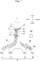
1 ist eine schematische Darstellung, welche zeigt, dass in einem Niederdrehzahlbereich (z.B. während eines Niederdrehzahlbetriebs des Motors, z.B. des Verbrennungsmotors) Luft in einen ersten Kanal gemäß der vorliegenden Erfindung hinein zugeführt wird.1 12 is a schematic diagram showing that in a low speed range (eg, during low speed operation of the engine, eg, the internal combustion engine), air is supplied into a first duct according to the present invention. -
2 ist eine schematische Darstellung, welche zeigt, dass in einem Niederdrehzahlbereich Luft in einen zweiten Kanal gemäß der vorliegenden Erfindung hinein zugeführt wird.2 Fig. 12 is a schematic diagram showing that in a low speed range, air is supplied into a second duct according to the present invention. -
3 ist eine schematische Darstellung, welche zeigt, dass in einem Hochdrehzahlbereich Luft in einen ersten Kanal und einen zweiten Kanal gemäß der vorliegenden Erfindung hinein zugeführt wird.3 12 is a schematic diagram showing that in a high speed range, air is supplied into a first duct and a second duct according to the present invention. -
4 ist eine Querschnittansicht eines Abschnitts „A“ der1 , welcher eine Querschnittansicht eines Luftsteuerventils gemäß der vorliegenden Erfindung ist.4 12 is a cross-sectional view of a portion "A" of FIG1 12, which is a cross-sectional view of an air control valve according to the present invention. -
5 ist ein Blockdiagramm des beispielhaften Einlasssystems gemäß der vorliegenden Erfindung.5 Figure 12 is a block diagram of the exemplary intake system in accordance with the present invention.
Es sollte klar sein, dass die angehängten Zeichnungen nicht notwendigerweise maßstabsgetreu sind und eine etwas vereinfachte Darstellungsweise von verschiedenen Merkmalen darstellen, welche die Grundprinzipien der Erfindung aufzeigen. Die spezifischen Konstruktionsmerkmale der vorliegenden Erfindung, unter anderem z.B. konkrete Abmessungen, Richtungen, Positionen und Formen, wie sie hierin offenbart sind, werden teilweise von der jeweiligen geplanten Anwendung und Nutzungsumgebung vorgegeben.It should be understood that the appended drawings are not necessarily to scale, presenting a somewhat simplified representation of various features and indicating the principles of the invention. The specific design features of the present invention, including but not limited to, the specific dimensions, directions, locations, and shapes disclosed herein will be dictated in part by the particular intended application and use environment.
Detaillierte BeschreibungDetailed description
Die
Wie es in den
Das Luftsteuerventil 50 steuert einen Pfad von der Luft, welche in den Ladeluftkühler 10 in Übereinstimmung mit einer Zündreihenfolge hinein zugeführt wird. Wie es in der
Das Steuergehäuse 51 ist um einen Umfang der Innenseitenfläche der Luftleitung 3 herum geformt. Eine Querschnittgestalt des Steuergehäuses 51 entspricht im Wesentlichen der der Luftleitung 3. Das heißt, falls die Querschnittgestalt der Luftleitung 3 in einer Kreisgestalt geformt ist, kann das Steuergehäuse 51 in einer Ringgestalt geformt sein, aber es ist nicht darauf beschränkt. Die Steuerplatte 52 ist in einer Gestalt geformt, welche (zumindest im Wesentlichen) die Hälfte des Steuergehäuses 51 ist, und ist mit einem Inneren des Steuergehäuses 51 gekuppelt, um drehbar zu sein. Falls die Querschnittgestalt des Steuergehäuses 51 in einer Ringgestalt geformt ist, kann die Steuerplatte 52 in einer Halbkreisgestalt geformt sein, aber sie ist darauf nicht beschränkt. Die Steuerplatte 52 kann irgendeine Gestalt haben, sodass ein Teil(bereich) einer Innenseite des Steuergehäuses 51 selektiv geschlossen ist/wird. Die Steuerplatte 52 ist eingerichtet, um die Luft zu blockieren. Der Offen-Abschnitt 53 ist in solch einer Gestalt geformt, dass es der Luft erlaubt wird, dort hindurch zu treten, wenn dieser in der Zeichnung rechts und/oder links offen ist (d.h., der Offen-Abschnitt 53 wird z.B. von einer Achse in einer Oben-unten-Richtung in den Zeichnungen begrenzt). Deshalb ist die Luft(strömung), wie es in der
Ein Basisabschnitt 55 ist mit der Steuerplatte 52 gekuppelt, um durch eine Mitte des Steuergehäuses 51 hindurchzutreten. Der Basisabschnitt 55 kann integral mit der Steuerplatte 52 geformt sein, und die zugehörigen Enden des Basisabschnitts 55 können mit der Innenseite des Steuergehäuses 51 gekuppelt sein. Die Steuerplatte 52 kann durch den Basisabschnitt 55 fixiert sein, um sich mit Bezug auf den Basisabschnitt 55 in einer Richtung im oder entgegen dem Uhrzeigersinn zu drehen. Als solches wird die Steuerplatte 52 gedreht, und deshalb können die Steuerplatte 52 und der Offen-Abschnitt 53 eine Position untereinander ändern (d.h. der Offen-Abschnitt und die Steuerplatte können ihre Position tauschen).A
Wenn die Steuerplatte 52 gedreht wird/ist, ist eine Seite der Steuerplatte 52 (z.B. ein Rand bzw. ein Ende der Steuerplatte 52) eingerichtet, um selektiv mit einer Innenseitenfläche (Der Luftleitung) in einer Links- oder Rechts-Richtung in der Zeichnung (vgl. z.B. die
Der Ladeluftkühler 10 ist eingerichtet, um die Luft zu kühlen, welche vom Luftsteuerventil 50 aus zugeführt wird, und speist die gekühlte Luft in den Einlasskrümmer 100 hinein ein. Der Ladeluftkühler 10 kann ein wassergekühlter Ladeluftkühler sein, welcher eingerichtet ist, um Luft durch Wärmeaustausch mit einem Kühlmittel (z.B. Kühlwasser) zu kühlen, aber er ist nicht darauf beschränkt. Der Ladeluftkühler 10 ist mit einer Trennstruktur (z.B. einer Trennwand) 15 bereitgestellt, welche zum Basisabschnitt 55 in einer Vertikalrichtung in der Zeichnung korrespondiert (z.B. zu einer Oben-Unten-Richtung in der
Der Ladeluftkühler 10 kann mit einer ersten Luftleitung 11, welche mit Bezug auf die Trennstruktur 15 links angeordnet ist, und einer zweiten Luftleitung 12 bereitgestellt sein, welche mit Bezug auf die Trennstruktur 15 rechts angeordnet ist.The
Die erste Luftleitung 11 oder die zweite Luftleitung 12 können selektiv vom Luftsteuerventil 50 die Luft empfangen oder nicht empfangen. Das heißt, falls die Steuerplatte 52 die linke Seite der Luftleitung 3 blockiert, dann ist die Luft, welche durch das Luftsteuerventil 50 hindurch tritt, eingerichtet, um in der zweiten Luftleitung 12 zu strömen. Falls die Steuerplatte 52 die rechte Seite der Luftleitung 3 blockiert, dann ist die Luft, welche durch das Luftsteuerventil 50 hindurch tritt, eingerichtet, um in die erste Luftleitung 11 hinein zugeführt zu werden.The
Der Einlasskrümmer 100 ist eingerichtet, um die Luft, welche durch den Ladeluftkühler 10 hindurch tritt, in jeden Zylinder 70 hinein zuzuführen. Der Einlasskrümmer 100 weist den ersten Kanal 101 und den zweiten Kanal 102 auf. Der erste Kanal 101 ist eingerichtet, um mit der ersten Luftleitung 11 verbunden zu sein und um die Luft, welche von der ersten Leitung 11 zugeführt wird, in zumindest einen Zylinder 70 hinein auszugeben. Der zweite Kanal 102 ist eingerichtet, um mit der zweiten Luftleitung 12 verbunden zu sein und um die Luft, welche von der zweiten Luftleitung 12 aus zugeführt wird, in zumindest einen Zylinder 70 hinein auszugeben. Wie es in der
Der erste Kanal 101 und der zweite Kanal 102 können in einer Längsrichtung der Luftleitung 3 symmetrisch sein (z.B. können die beiden Kanäle gleich lang und/oder z.B. symmetrisch verzweigt sein, d.h., können z.B. zumindest im Wesentlichen einen gleichen Strömungswiderstand haben). Deshalb kann die Luft, welche durch den ersten Kanal 101 oder den zweiten Kanal 102 hindurch tritt, gleichmäßig / zu gleichen Teilen in jeden Zylinder 70 hinein zugeführt werden.The
Das Einlasssystem 1 weist weiter eine Steuerungsvorrichtung 200 auf, um ein Drehungsmaß der Steuerplatte 52 zu steuern. Die Steuerungsvorrichtung 200 kann durch einen oder mehrere Prozessoren umgesetzt sein, welche/r durch ein vorbestimmtes Programm aktiviert werden/wird.The
Die
Wie es in der
Die Steuerungsvorrichtung 200 steuert das Drehungsmaß der Steuerplatte 52 auf der Basis von Informationen, welche von der Sensorvorrichtung 150 übertragen werden, wie beispielsweise der Drehzahl oder der Zündreihenfolge des Motors.The
In der folgenden Beschreibung, wenn die Drehzahl des Motors niedriger ist als eine vorbestimmte Drehzahl, ist dies als ein Niederdrehzahlbereich bezeichnet, und, wenn die Drehzahl des Motors die vorbestimmte Drehzahl überschreitet, ist dies als ein Hochdrehzahlbereich bezeichnet.In the following description, when the rotation speed of the engine is lower than a predetermined rotation speed, it is referred to as a low-speed range, and when the rotation speed of the engine exceeds the predetermined rotation speed, it is referred to as a high-speed range.
Die
Die
Wie es oben beschrieben ist, kann die Luft selektiv dem ersten Kanal 101 oder dem zweiten Kanal 102 separat in Übereinstimmung mit einer Zündreihenfolge eines jeden Zylinders während des Niederdrehzahlbereichs des Motors zugeführt werden. Deshalb kann die Motoreffizienz gleich zu der der herkömmlichen Technik sein, trotz einer relativ gering(er)en Luftmenge. Im Detail soll in einem herkömmlichen Einlasssystem Luft (gleichzeitig) zu allen Zylindern 70 zugeführt werden, wie beispielsweise dem ersten, dem zweiten, dem dritten und dem vierten Zylinder 71, 72, 73 und 74. Jedoch kann gemäß der vorliegenden Erfindung die Luft (selektiv auch) nur dem ersten und dem vierten Zylinder 71, 74 oder dem zweiten und dem dritten Zylinder 72 und 73 zugeführt werden. Da der erste Kanal 101 und der zweite Kanal 102 voneinander separat sind, kann eine Strömungsinterferenz im Einlasskrümmer 100 moderat/abgeschwächt sein. Weiter, wenn die Menge der (dem Motor zugeführten) Luft reduziert ist, kann die Effizienz des Ladeluftkühlers 10 verbessert sein.As described above, the air can be selectively supplied to the
Die
Die Steuerungsvorrichtung 200 steuert die Steuerplatte 52, um in einer Längsrichtung der Luftleitung 3 positioniert zu sein (z.B. zumindest im Wesentlichen parallel zu dieser). Das heißt, die Steuerplatte 52 ist eingerichtet, um sich in einer Oben-Unten-Richtung zu befinden. Deshalb kann die Luft durch den Offen-Abschnitt 53 hindurch treten, welcher an beiden Seiten der Luftleitung 3 geformt ist. Die Luft, welche durch den Offen-Abschnitt 53 hindurch tritt, wird zu allen Zylindern 70 durch den ersten Kanal und den zweiten Kanal 102 durch Geführt-Werden durch die erste Luftleitung 11 und die zweite Luftleitung 12 hindurch zugeführt. Zum Beispiel kann die Luft in den ersten, den zweiten, den dritten und den vierten Zylinder 71, 72, 73 und 74 hinein zugeführt werden. Dementsprechend wird die Menge der Luft während des Hochdrehzahlbereichs ausreichend zugeführt, und eine Ausgabeleistung des Motors kann verbessert sein.The
Wie es oben beschrieben ist, gemäß zahlreichen Ausführungsformen der vorliegenden Erfindung, steuert das Luftsteuerventil 50 die Strömungsrate und/oder den Pfad der Luft in Übereinstimmung mit der Zündreihenfolge und/oder der Drehzahl des Motors. Die Strömungsrate der Luft ist eingerichtet, um basierend auf einer Motorbedingung (z.B. einer Motordrehzahl) in jeden Zylinder 70 hinein geströmt zu werden. Das heißt, wenn die Drehzahl des Motors niedriger ist als die vorbestimmte Drehzahl, wird die Luft(-Strömung), welche durch das Luftsteuerventil 50 hindurch tritt, reduziert, wodurch die Kühlungseffizienz des Ladeluftkühlers 10 verbessert sein kann.As described above, according to various embodiments of the present invention, the
Ebenfalls kann die Einlassinterferenz minimiert sein und kann die Einlasseffizienz eines jeden Zylinder 70 verbessert sein, wenn die Luft, welche in den Einlasskrümmer 100 hinein zugeführt wird, in jeden Zylinder 70 durch die separate Passage hinein gespeist/geleitet wird.Also, when the air supplied into the
Darüber hinaus, falls die Einlasseffizienz eines jeden Zylinders 70 verbessert ist, liegen Effekte des Verringerns des Kraftstoffverbrauchs vor.Furthermore, if the intake efficiency of each
Zur Erleichterung der Erklärung und zur genauen Definition in den angehängten Ansprüchen werden die Begriffe „oben“ oder „unten“, „innen“ oder „außen“ und etc. verwendet, um Merkmale der beispielhaften Ausführungsformen mit Bezug auf die Positionen der in den Figuren gezeigten Merkmale zu beschreiben.For ease of explanation and for precise definition in the appended claims, the terms "top" or "bottom", "inside" or "outside" and etc. are used to identify features of the exemplary embodiments with reference to the positions of those shown in the figures to describe characteristics.
Claims (13)
Applications Claiming Priority (2)
| Application Number | Priority Date | Filing Date | Title |
|---|---|---|---|
| KR1020140166790A KR101610164B1 (en) | 2014-11-26 | 2014-11-26 | Intake system |
| KR10-2014-0166790 | 2014-11-26 |
Publications (2)
| Publication Number | Publication Date |
|---|---|
| DE102015114372A1 DE102015114372A1 (en) | 2016-06-02 |
| DE102015114372B4 true DE102015114372B4 (en) | 2022-10-13 |
Family
ID=55908047
Family Applications (1)
| Application Number | Title | Priority Date | Filing Date |
|---|---|---|---|
| DE102015114372.0A Expired - Fee Related DE102015114372B4 (en) | 2014-11-26 | 2015-08-28 | intake system |
Country Status (3)
| Country | Link |
|---|---|
| US (1) | US9816469B2 (en) |
| KR (1) | KR101610164B1 (en) |
| DE (1) | DE102015114372B4 (en) |
Citations (3)
| Publication number | Priority date | Publication date | Assignee | Title |
|---|---|---|---|---|
| DE4433165C1 (en) | 1994-09-16 | 1995-12-21 | Mtu Friedrichshafen Gmbh | Plate=type heat exchanger |
| DE19858771A1 (en) | 1997-12-22 | 1999-07-01 | Avl List Gmbh | Multicylinder internal combustion engine |
| DE102012022416A1 (en) | 2011-11-30 | 2013-06-06 | Cummins Intellectual Property, Inc. | Intercooler arrangement |
Family Cites Families (10)
| Publication number | Priority date | Publication date | Assignee | Title |
|---|---|---|---|---|
| US5337724A (en) | 1991-09-30 | 1994-08-16 | Mazda Motor Corporation | Intake system for an internal combustion engine with a supercharger |
| US5551387A (en) * | 1995-02-24 | 1996-09-03 | Ortech Corporation | Tuned intake manifold for OTTO cycle engines |
| US6955149B1 (en) * | 2004-08-05 | 2005-10-18 | General Motors Corporation | Variable intake manifold with trimode resonance tuning control valve |
| KR20070023084A (en) | 2005-08-23 | 2007-02-28 | 현대자동차주식회사 | Swirl control valve |
| JPWO2008108234A1 (en) | 2007-02-20 | 2010-06-10 | トヨタ自動車株式会社 | Internal combustion engine |
| JP2011190744A (en) * | 2010-03-15 | 2011-09-29 | Denso Corp | Intake air cooling device for internal combustion engine |
| KR101628402B1 (en) | 2010-12-06 | 2016-06-08 | 현대자동차주식회사 | Apparatus for cooling the charged air of Diesel Engine with water cooling type intercooler and cooling method therefor |
| JP5948883B2 (en) * | 2012-01-17 | 2016-07-06 | マツダ株式会社 | Engine intake system |
| KR20140076218A (en) | 2012-12-12 | 2014-06-20 | 현대자동차주식회사 | Cooling system using engine cover for vehicle |
| DE102014000450B4 (en) * | 2013-02-18 | 2016-02-18 | Modine Manufacturing Company | Inlet manifold with intercooler |
-
2014
- 2014-11-26 KR KR1020140166790A patent/KR101610164B1/en active IP Right Grant
-
2015
- 2015-08-07 US US14/821,410 patent/US9816469B2/en active Active
- 2015-08-28 DE DE102015114372.0A patent/DE102015114372B4/en not_active Expired - Fee Related
Patent Citations (3)
| Publication number | Priority date | Publication date | Assignee | Title |
|---|---|---|---|---|
| DE4433165C1 (en) | 1994-09-16 | 1995-12-21 | Mtu Friedrichshafen Gmbh | Plate=type heat exchanger |
| DE19858771A1 (en) | 1997-12-22 | 1999-07-01 | Avl List Gmbh | Multicylinder internal combustion engine |
| DE102012022416A1 (en) | 2011-11-30 | 2013-06-06 | Cummins Intellectual Property, Inc. | Intercooler arrangement |
Also Published As
| Publication number | Publication date |
|---|---|
| US20160146166A1 (en) | 2016-05-26 |
| KR101610164B1 (en) | 2016-04-08 |
| US9816469B2 (en) | 2017-11-14 |
| DE102015114372A1 (en) | 2016-06-02 |
Similar Documents
| Publication | Publication Date | Title |
|---|---|---|
| DE102015111390A1 (en) | Internal combustion engine system with coolant control valve | |
| DE102010010594B4 (en) | Cooling circuit for an internal combustion engine | |
| DE102019101242B4 (en) | Thermal management system and method for a vehicle | |
| DE102014116762B4 (en) | Combustion engine with coolant control valve | |
| DE102016207771B4 (en) | Hybrid charge air cooler system using multiple cooling media and method of controlling the hybrid charge air cooler system using multiple cooling media | |
| DE102013206082A1 (en) | Device and method for engine warm-up | |
| DE102014117557B4 (en) | automotive engine cooling system | |
| EP2522843A1 (en) | Supercharged internal combustion engine with separate exhaust manifolds and method to operate such an engine | |
| DE102015116168A1 (en) | Engine system, which has two cooling circuits | |
| DE102014114218A1 (en) | COMBUSTION ENGINE SYSTEM WITH TURBOLADER | |
| DE102018104026A1 (en) | ENGINE CONTROL | |
| DE102019105893A1 (en) | Thermal management system and method for a vehicle drive system | |
| EP3853453B1 (en) | Cooling system and method for configuring a cooling system | |
| DE102014117876B4 (en) | Coolant control valve that selectively supplies coolant to an EGR cooler | |
| DE102017221062A1 (en) | Exhaust gas recirculation device | |
| DE102015113069A1 (en) | intake system | |
| DE102015115680A1 (en) | Radiator for a vehicle | |
| DE102014117872B4 (en) | Vehicle air flow control system | |
| DE102015114372B4 (en) | intake system | |
| DE102014117661B4 (en) | Cooling device for a bus | |
| DE102017207363A1 (en) | COMBUSTION ENGINE CYLINDER HEAD WITH INTEGRATED EXHAUST GASKET WITH MULTIPLE CHANNELS AND MULTIPLE CONNECTIONS | |
| EP3374620B1 (en) | Internal combustion engine | |
| DE102013011563B4 (en) | Cooling circuit of an internal combustion engine and method for operating a cooling circuit | |
| EP1284343B1 (en) | Cooling system for a motor vehicle and related motor vehicle | |
| DE102021123698A1 (en) | Test bench for an engine |
Legal Events
| Date | Code | Title | Description |
|---|---|---|---|
| R012 | Request for examination validly filed | ||
| R016 | Response to examination communication | ||
| R018 | Grant decision by examination section/examining division | ||
| R020 | Patent grant now final | ||
| R119 | Application deemed withdrawn, or ip right lapsed, due to non-payment of renewal fee |