DE102015114239B3 - Method for adjusting the print quality of an electrophotographic printer - Google Patents
Method for adjusting the print quality of an electrophotographic printer Download PDFInfo
- Publication number
- DE102015114239B3 DE102015114239B3 DE102015114239.2A DE102015114239A DE102015114239B3 DE 102015114239 B3 DE102015114239 B3 DE 102015114239B3 DE 102015114239 A DE102015114239 A DE 102015114239A DE 102015114239 B3 DE102015114239 B3 DE 102015114239B3
- Authority
- DE
- Germany
- Prior art keywords
- transfer
- photoconductor
- transfer roller
- toner
- voltage
- Prior art date
- Legal status (The legal status is an assumption and is not a legal conclusion. Google has not performed a legal analysis and makes no representation as to the accuracy of the status listed.)
- Expired - Fee Related
Links
Images


Classifications
-
- G—PHYSICS
- G03—PHOTOGRAPHY; CINEMATOGRAPHY; ANALOGOUS TECHNIQUES USING WAVES OTHER THAN OPTICAL WAVES; ELECTROGRAPHY; HOLOGRAPHY
- G03G—ELECTROGRAPHY; ELECTROPHOTOGRAPHY; MAGNETOGRAPHY
- G03G15/00—Apparatus for electrographic processes using a charge pattern
- G03G15/50—Machine control of apparatus for electrographic processes using a charge pattern, e.g. regulating differents parts of the machine, multimode copiers, microprocessor control
- G03G15/5033—Machine control of apparatus for electrographic processes using a charge pattern, e.g. regulating differents parts of the machine, multimode copiers, microprocessor control by measuring the photoconductor characteristics, e.g. temperature, or the characteristics of an image on the photoconductor
- G03G15/5041—Detecting a toner image, e.g. density, toner coverage, using a test patch
-
- G—PHYSICS
- G03—PHOTOGRAPHY; CINEMATOGRAPHY; ANALOGOUS TECHNIQUES USING WAVES OTHER THAN OPTICAL WAVES; ELECTROGRAPHY; HOLOGRAPHY
- G03G—ELECTROGRAPHY; ELECTROPHOTOGRAPHY; MAGNETOGRAPHY
- G03G15/00—Apparatus for electrographic processes using a charge pattern
- G03G15/06—Apparatus for electrographic processes using a charge pattern for developing
- G03G15/10—Apparatus for electrographic processes using a charge pattern for developing using a liquid developer
-
- G—PHYSICS
- G03—PHOTOGRAPHY; CINEMATOGRAPHY; ANALOGOUS TECHNIQUES USING WAVES OTHER THAN OPTICAL WAVES; ELECTROGRAPHY; HOLOGRAPHY
- G03G—ELECTROGRAPHY; ELECTROPHOTOGRAPHY; MAGNETOGRAPHY
- G03G15/00—Apparatus for electrographic processes using a charge pattern
- G03G15/14—Apparatus for electrographic processes using a charge pattern for transferring a pattern to a second base
- G03G15/16—Apparatus for electrographic processes using a charge pattern for transferring a pattern to a second base of a toner pattern, e.g. a powder pattern, e.g. magnetic transfer
- G03G15/1605—Apparatus for electrographic processes using a charge pattern for transferring a pattern to a second base of a toner pattern, e.g. a powder pattern, e.g. magnetic transfer using at least one intermediate support
Landscapes
- Engineering & Computer Science (AREA)
- Microelectronics & Electronic Packaging (AREA)
- Physics & Mathematics (AREA)
- General Physics & Mathematics (AREA)
- Electrostatic Charge, Transfer And Separation In Electrography (AREA)
Abstract
Mit einem Verfahren, bei dem das Oberflächenpotential eines ein Testtonerbild aufweisenden Messfelds auf dem Fotoleiter nach dem Transfer dieses Testtonerbildes auf eine Transferwalze mit einer Potenzialmesssonde gemessen wird, kann die Effizienz des Transfers von Tonerbildern vom Fotoleiter auf die Transferwalze ermittelt werden. Die Transferwalzenspannung an der Transferwalze kann so eingestellt werden, dass das von der Potenzialmesssonde gemessene Oberflächenpotenzial des Messfeldes ein Minimum annimmt.With a method in which the surface potential of a measuring field having a test toner image is measured on the photoconductor after transferring this test toner image to a transfer roller with a potential measuring probe, the efficiency of transfer of toner images from the photoconductor to the transfer roller can be determined. The transfer roll tension at the transfer roll can be adjusted so that the surface potential of the measuring field measured by the potential measuring probe assumes a minimum.

Description
Die Erfindung betrifft einen elektrofotografischen Drucker zum Bedrucken eines Aufzeichnungsträgers mit Tonerpartikeln eines Entwicklergemischs, die mit Hilfe eines Flüssigentwicklers aufgetragen werden.The invention relates to an electrophotographic printer for printing a recording medium with toner particles of a developer mixture, which are applied by means of a liquid developer.
Bei solchen Druckern wird ein auf einem Fotoleiter erzeugtes Ladungsbild mit Hilfe des Flüssigentwicklers mittels Elektrophorese eingefärbt. Das so entstandene Tonerbild wird mittelbar über ein Transferelement oder unmittelbar auf den Aufzeichnungsträger übertragen. Der Flüssigentwickler weist in einem gewünschten Verhältnis Tonerpartikel und Trägerflüssigkeit auf. Als Trägerflüssigkeit wird vorzugsweise Mineralöl verwendet. Um die Tonerpartikel mit einer elektrostatischen Ladung zu versehen, können dem Flüssigentwickler Ladungssteuerstoffe hinzugefügt werden. Zusätzlich können weitere Additive zugegeben werden, um beispielsweise die gewünschte Viskosität oder ein gewünschtes Trocknungsverhalten des Flüssigentwicklers zu erhalten.In such printers, a charge image formed on a photoconductor is colored by electrophoresis with the aid of the liquid developer. The resulting toner image is transferred indirectly via a transfer element or directly onto the recording medium. The liquid developer has toner particles and carrier liquid in a desired ratio. The carrier liquid used is preferably mineral oil. To provide the toner particles with an electrostatic charge, charge control agents may be added to the liquid developer. In addition, further additives may be added to obtain, for example, the desired viscosity or drying behavior of the liquid developer.
Solche Drucker sind bekannt, beispielsweise aus
Ein Druckwerk eines elektrofotografischen Druckers besteht im Wesentlichen aus einer Elektrofotografiestation, einer Entwicklerstation und einer Transferstation. Kern der Elektrofotografiestation ist ein fotoelektrischer Bildträger, der an seiner Oberfläche eine fotoelektrische Schicht aufweist (ein sogenannter Fotoleiter). Der Fotoleiter ist z. B. als Fotoleiterwalze ausgebildet, die sich an verschiedenen Elementen zum Erzeugen eines Druckbildes vorbei dreht. Der Fotoleiter wird zunächst von allen Verunreinigungen gereinigt. Hierzu ist eine Löschlichteinrichtung vorhanden, die noch auf der Oberfläche des Fotoleiters verbliebene Ladungen löscht. Nach der Löschlichteinrichtung reinigt eine Reinigungseinrichtung den Fotoleiter mechanisch ab, um gegebenenfalls noch auf der Oberfläche des Fotoleiters vorhandene Tonerpartikel, gegebenenfalls Schmutzpartikel und verbliebene Trägerflüssigkeit zu entfernen. Anschließend wird der Fotoleiter durch eine Aufladeeinrichtung auf ein vorbestimmtes elektrostatisches Aufladepotenzial aufgeladen. Hierzu weist die Aufladeeinrichtung z. B. eine Korotroneinrichtung auf. Durch Einstellung des Stroms, der der Korotroneinrichtung zugeführt wird, ist das Aufladepotenzial des Fotoleiters steuerbar. Nach der Aufladeeinrichtung ist ein Zeichengenerator angeordnet, der über optische Strahlung den Fotoleiter je nach gewünschtem Druckbild entlädt. Dadurch entsteht ein Ladungsbild des Druckbilds.A printing unit of an electrophotographic printer essentially consists of an electrophotography station, a developer station and a transfer station. The core of the electrophotography station is a photoelectric image carrier having on its surface a photoelectric layer (a so-called photoconductor). The photoconductor is z. B. formed as a photoconductor roller, which rotates past various elements for generating a printed image. The photoconductor is first cleaned of all impurities. For this purpose, a Löschlichteinrichtung is present, which deletes still remaining on the surface of the photoconductor charges. After the extinguishing device, a cleaning device mechanically cleans the photoconductor, in order to remove any toner particles, if necessary dirt particles and residual carrier liquid, which may still be present on the surface of the photoconductor. Subsequently, the photoconductor is charged by a charging device to a predetermined electrostatic charging potential. For this purpose, the charging device z. B. on a corotron device. By adjusting the current supplied to the corotron device, the charging potential of the photoconductor is controllable. After the charging device, a character generator is arranged, which discharges the photoconductor via optical radiation depending on the desired printed image. This creates a charge image of the printed image.
Das durch den Zeichengenerator erzeugte Ladungsbild des Druckbilds wird durch die Entwicklerstation mit Tonerpartikeln eingefärbt. Die Entwicklerstation weist hierzu z. B. eine sich drehende Entwicklerwalze auf, die eine Schicht Flüssigentwickler an den Fotoleiter heranführt. Zwischen dem Fotoleiter und der Entwicklerwalze besteht ein Entwicklungsnip, in dem ein elektrisches Feld erzeugt wird, auf Grund dessen die geladenen Tonerpartikel elektrophoretisch von der Entwicklerwalze auf den Fotoleiter zu den Bildstellen auf dem Fotoleiter wandern. In den Nichtbildstellen geht kein Toner auf den Fotoleiter über, weil die Richtung des elektrischen Feldes, das sich aus dem Potenzial auf der Entwicklerwalze und dem Aufladepotenzial an der Entwicklungsstelle auf dem Fotoleiter ergibt, die geladenen Tonerpartikel abstößt.The charge image generated by the character generator of the print image is colored by the developer station with toner particles. The developer station has z. For example, a rotating developer roll advances a layer of liquid developer to the photoconductor. Between the photoconductor and the developer roller there is a development nip in which an electric field is generated, as a result of which the charged toner particles electrophoretically migrate from the developer roller onto the photoconductor to the image locations on the photoconductor. In the non-image areas, toner does not transfer to the photoconductor because the direction of the electric field resulting from the potential on the developer roller and the charge potential at the development site on the photoconductor repels the charged toner particles.
Das eingefärbte Bild, das Tonerbild, dreht sich mit dem Fotoleiter bis zu einer Transferstelle, bei der das Tonerbild auf eine Transferwalze oder auf den Aufzeichnungsträger direkt übertragen wird. Von der Transferwalze kann das Tonerbild auf den Aufzeichnungsträger zum Druckbild umgedruckt werden.The inked image, the toner image, rotates with the photoconductor to a transfer point where the toner image is transferred directly to a transfer roller or to the recording medium. From the transfer roller, the toner image can be printed on the recording medium to the printed image.
Wichtig für eine hochwertige Druckqualität ist ein effektiver und stabiler elektrophoretischer Transfer vom Fotoleiter auf nachfolgende Komponenten wie z. B. eine Transferwalze oder einen Aufzeichnungsträger. Derzeit kann die Transfereffizienz vom Fotoleiter auf die Transferwalze z. B. indirekt über die Messung der Tonerkonzentration in der Fotoleiterreinigung bestimmt werden. Diese Messung ist aufgrund von Schwankungen der Reinigungseffizienz und der angetragenen Tonermenge ungenau und langsam, da der Toner für ein ausreichendes Probenvolumen mehrere Minuten gesammelt werden muss.Important for a high-quality print quality is an effective and stable electrophoretic transfer from the photoconductor to downstream components such. B. a transfer roller or a recording medium. Currently, the transfer efficiency of the photoconductor on the transfer roller z. B. be determined indirectly via the measurement of toner concentration in the photoconductive cleaning. This measurement is inaccurate and slow due to variations in cleaning efficiency and the amount of toner applied, as the toner must be collected for several minutes for a sufficient sample volume.
In
Der Erfindung liegt das Problem zugrunde, ein Verfahren für einen elektrofotografischen Drucker zum Bedrucken eines Aufzeichnungsträgers anzugeben, mit dem der Transfer von Tonerbildern von einem Fotoleiter auf ein Übernahmemittel für die Tonerbilder, z. B. auf eine Transferwalze einer Transferstation oder einen Aufzeichnungsträger, optimiert wird.The invention is based on the problem, a method for an electrophotographic printer for printing a recording medium with the transfer of toner images from a photoconductor on a takeover means for the toner images, z. B. on a transfer roller of a transfer station or a recording medium is optimized.
Dieses Problem wird bei einem Digitaldrucker zum Bedrucken eines Aufzeichnungsträgers mit einem Verfahren mit den Merkmalen von Anspruch 1 gelöst. Vorteilhafte Ausgestaltungen der Erfindung sind in den Unteransprüchen wiedergegeben.This problem is solved in a digital printer for printing a record carrier by a method having the features of claim 1. Advantageous embodiments of the invention are given in the dependent claims.
In der folgenden Erläuterung der Erfindung wird als Beispiel eines Übernahmemittels für Tonerbilder eine Transferwalze angenommen, auf die über eine Transferstelle vom Fotoleiter die Tonerbilder übertragen werden. Als Transferstelle wird dabei der Nip zwischen dem Fotoleiter und der Transferwalze bezeichnet. Um den Übergang der Tonerbilder auf die Transferwalze über die Transferstelle zu fördern, kann über die Transferstelle eine Transferspannung gelegt werden, die so gepolt ist, dass der Toner vom Fotoleiter zur Transferwalze gezogen wird. Zur Einstellung dieser Transferspannung kann an die Transferwalze eine Transferwalzenspannung angelegt werden, die das Potenzial auf der Oberfläche der Transferwalze festlegt.In the following explanation of the invention, as an example of a transfer means for toner images, a transfer roller to which the toner images are transferred by a photoconductor via a transfer site is assumed. The transfer point is the nip between the photoconductor and the transfer roller. In order to promote the transfer of the toner images on the transfer roller via the transfer point, a transfer voltage can be applied via the transfer point, which is polarized so that the toner is drawn from the photoconductor to the transfer roller. To set this transfer voltage, a transfer roller tension can be applied to the transfer roller, which sets the potential on the surface of the transfer roller.
Mit einem Verfahren, bei dem das Oberflächenpotential eines ein Testtonerbild aufweisenden Messfelds auf dem Fotoleiter nach dem Transfer dieses Testtonerbildes mit einer Potenzialmesssonde gemessen wird, kann die Effizienz des Transfers von Tonerbildern vom Fotoleiter auf die Transferwalze ermittelt werden. Die Transferwalzenspannung an der Transferwalze kann so eingestellt werden, dass das von der Potenzialmesssonde gemessene Oberflächenpotenzial ein Minimum annimmt. Alternativ kann der Transfer der Tonerbilder vom Fotoleiter auf die Transferwalze auf das Verhältnis der Oberflächenpotenziale des Messfeldes auf dem Fotoleiter vor und nach der Transferstelle geregelt werden. Als Testtonerbild kann das Tonerbild eines Druckbildes verwendet werden oder es kann ein besonders gestaltetes Tonerbild eingesetzt werden.With a method in which the surface potential of a measuring field having a test toner image is measured on the photoconductor after the transfer of this test toner image with a potential measuring probe, the efficiency of the transfer of toner images from the photoconductor to the transfer roller can be determined. The transfer roll tension at the transfer roll can be adjusted so that the surface potential measured by the potential probe becomes a minimum. Alternatively, the transfer of the toner images from the photoconductor to the transfer roller can be controlled to the ratio of surface potentials of the measurement field on the photoconductor before and after the transfer site. As a toner toner image, the toner image of a printed image may be used, or a specially designed toner image may be used.
Durch die Regelung des Transfers der Tonerbilder vom Fotoleiter auf die Transferwalze kann sichergestellt werden, dass die Effizienz beim Transfer der Tonerbilder vom Fotoleiter zur Transferwalze nahe am oder im Optimum liegt, d. h. die Druckqualität wird optimiert und zudem die nachfolgende Fotoleiterreinigung entlastet. Insbesondere bei einem Wechsel der Transferwalze kann eine chargenbedingte Variation in der elektrischen Leitfähigkeit zu einer Veränderung der optimalen Transferspannung über die Transferstelle führen. Zudem machen Alterungseffekte eine kontinuierliche Optimierung erforderlich.By controlling the transfer of the toner images from the photoconductor to the transfer roller, it can be ensured that the efficiency in transferring the toner images from the photoconductor to the transfer roller is close to or at the optimum; H. the print quality is optimized and also the subsequent photoconductive cleaning is relieved. In particular when the transfer roller is changed, a charge-related variation in the electrical conductivity can lead to a change in the optimum transfer voltage via the transfer point. In addition, aging effects require continuous optimization.
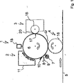
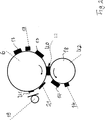
Ein Ausführungsbeispiel der Erfindung wird im Folgenden anhand der schematischen Figuren näher erläutert. Es zeigen:An embodiment of the invention will be explained in more detail below with reference to the schematic figures. Show it:
Der prinzipielle Aufbau eines elektrophoretischen Druckwerks
Das Druckwerk
Kern der Elektrofotografiestation
Der Fotoleiter
Nach der Löschlichteinrichtung
Anschließend wird der Fotoleiter
Das durch den Zeichengenerator
Das eingefärbte Bild, das Tonerbild, dreht sich mit dem Fotoleiter
Nach dem Transfer der Tonerbilder
Um den Transfer der Tonerbilder
Ziel der Erfindung ist es nun, die Transferwalzenspannung U2 derart einzustellen, dass die von den Tonerbildern
Ein Beispiel einer Messkurve MK kann
Aus der Messkurve MK kann somit die optimale Transferwalzenspannung U2opt abgelesen werden, bei der der Resttoner
Wenn bei der Messkurve MK die abfallende Flanke
Die Messkurve MK kann anhand von Tonerbildern von Druckbildern auf dem Fotoleiter
Vorteilhaft ist auch, zusätzlich zur Potenzialmesssonde
Die Effizienz des Tonerübergangs auf die Transferwalze
Um die Verhältnisse über die Breite des Fotoleiters
Der von der Potenzialmesssonde
Im Druckbetrieb kann die Messkurve MK in einer Druckersteuerung gespeichert werden und bei Abweichung des Oberflächenpotenzials U1 des Messfeldes vom Minimalwert die Transferwalzenspannung U2 um einen vorgegebenen Wert so geändert werden, dass die erste Potenzialmesssonde
Das Verfahren ist für die angegebenen Elemente des Druckgeräts wie Fotoleiterwalze
BezugszeichenlisteLIST OF REFERENCE NUMBERS
- U0U0
- Transferspannungtransfer voltage
- U1U1
-
Oberflächenpotenzial auf dem Fotoleiter
6 Surface potential on thephotoconductor 6 - U2U2
- TransferwalzenspannungTransfer roller voltage
- 11
- Druckwerkprinting unit
- 22
- ElektrofotografiestationElectrophotography station
- 33
- Entwicklerstationdeveloper station
- 44
- Transferstationtransfer station
- 55
- Aufzeichnungsträgerrecord carrier
- 66
- Fotoleiterphotoconductor
- 77
- LöschlichteinrichtungErasing light device
- 88th
- Reinigungseinrichtungcleaning device
- 99
- Auffangwannedrip tray
- 1010
- Rakeldoctor
- 1111
- Aufladeeinrichtungcharging
- 1212
- Transferstelletransfer Agent
- 1313
- Tonerbild auf dem FotoleiterToner image on the photoconductor
- 1414
- Tonerbild auf der TransferwalzeToner image on the transfer roller
- 1515
- ZeichengeratorZeichengerator
- 1616
- Entwicklerwalzedeveloper roller
- 1717
- Entwicklungsstelledevelopment office
- 1818
- Transferwalzetransfer roller
- 1919
- PotenzialmesssondePotential probe
- 2020
- Entwicklungspaltdevelopment gap
- 2121
- ResttonerbildResidual toner image
- 2222
- Abfallende Flanke von U1Falling edge of U1
- 2323
- Umkehrbereich von U1Reversal area of U1
- 2424
- Steigende Flanke von U1Rising edge of U1
Claims (3)
Priority Applications (1)
| Application Number | Priority Date | Filing Date | Title |
|---|---|---|---|
| DE102015114239.2A DE102015114239B3 (en) | 2015-08-27 | 2015-08-27 | Method for adjusting the print quality of an electrophotographic printer |
Applications Claiming Priority (1)
| Application Number | Priority Date | Filing Date | Title |
|---|---|---|---|
| DE102015114239.2A DE102015114239B3 (en) | 2015-08-27 | 2015-08-27 | Method for adjusting the print quality of an electrophotographic printer |
Publications (1)
| Publication Number | Publication Date |
|---|---|
| DE102015114239B3 true DE102015114239B3 (en) | 2016-09-15 |
Family
ID=56801224
Family Applications (1)
| Application Number | Title | Priority Date | Filing Date |
|---|---|---|---|
| DE102015114239.2A Expired - Fee Related DE102015114239B3 (en) | 2015-08-27 | 2015-08-27 | Method for adjusting the print quality of an electrophotographic printer |
Country Status (1)
| Country | Link |
|---|---|
| DE (1) | DE102015114239B3 (en) |
Citations (2)
| Publication number | Priority date | Publication date | Assignee | Title |
|---|---|---|---|---|
| DE4336690A1 (en) * | 1993-10-27 | 1995-05-04 | Henning Dipl Phys Dr Frunder | Device for measuring electrical potential contrasts (potential differences) |
| US5926669A (en) * | 1996-08-06 | 1999-07-20 | Ricoh Company, Ltd. | Image forming apparatus and method of forming an image with enhanced transfer condition settings |
-
2015
- 2015-08-27 DE DE102015114239.2A patent/DE102015114239B3/en not_active Expired - Fee Related
Patent Citations (2)
| Publication number | Priority date | Publication date | Assignee | Title |
|---|---|---|---|---|
| DE4336690A1 (en) * | 1993-10-27 | 1995-05-04 | Henning Dipl Phys Dr Frunder | Device for measuring electrical potential contrasts (potential differences) |
| US5926669A (en) * | 1996-08-06 | 1999-07-20 | Ricoh Company, Ltd. | Image forming apparatus and method of forming an image with enhanced transfer condition settings |
Similar Documents
| Publication | Publication Date | Title |
|---|---|---|
| DE19810788C2 (en) | Transmission bias control method for an image forming apparatus using the electrophotographic method | |
| DE2520810A1 (en) | METHOD AND DEVICE FOR APPLYING A PRELOAD VOLTAGE TO A DEVELOPMENT ELECTRODE OF AN ELECTROPHOTOGRAPHIC DEVICE | |
| WO2008101954A1 (en) | Method and device for detecting electric potential and electric charges in a printer or copier | |
| DE2555854B2 (en) | Electrostatic recording device | |
| DE2830461A1 (en) | METHOD AND DEVICE FOR CONTROLLING THE EDUCATION OF ELECTROPHOTOGRAPHIC IMAGES | |
| DE3637101A1 (en) | DEVICE WITH A PHOTO LADDER, IN PARTICULAR COPIER | |
| DE2325962A1 (en) | ELECTROPHOTOGRAPHIC COPYING PROCESS | |
| DE2558453C3 (en) | Device for developing an electrostatic charge image | |
| DE2855074A1 (en) | SURFACE POTENTIAL MEASURING DEVICE | |
| DE69725364T2 (en) | Image forming apparatus | |
| DE19730729B4 (en) | Color imaging device and associated color imaging method | |
| DE3728493C2 (en) | ||
| DE69733099T2 (en) | Cleaning method of a contact charging device in an electrographic device | |
| DE10001859A1 (en) | Electronic imaging device and method for controlling the same | |
| DE2145259A1 (en) | ELECTROPHOTOGRAPHIC DEVELOPMENT PROCESS | |
| DE2550846A1 (en) | DEVELOPMENT DEVICE FOR AN ELECTROPHOTOGRAPHIC COPY DEVICE | |
| DE69618335T2 (en) | Imaging device and charging element therefor | |
| DE3837528C2 (en) | Electrophotographic copier | |
| DE2925099C2 (en) | Developing device for an electrophotographic copier | |
| DE102009024600B4 (en) | Method and apparatus for transferring a quantity of electrically charged toner particles between at least two toner carriers | |
| DE2614318C3 (en) | Development method for an electrophotographic copier and apparatus for carrying out the method | |
| EP2100193B1 (en) | Method and device for processing a measurement signal for detecting a property of a toner mark | |
| DE102015107938A1 (en) | Method and developer station for adjusting the coloration of an image carrier of a toner-based digital printer | |
| DE102013101446B4 (en) | Method for adjusting the print quality of an electrophotographic printer | |
| DE69125406T2 (en) | Charger |
Legal Events
| Date | Code | Title | Description |
|---|---|---|---|
| R012 | Request for examination validly filed | ||
| R079 | Amendment of ipc main class |
Free format text: PREVIOUS MAIN CLASS: G03G0015000000 Ipc: G03G0015160000 |
|
| R016 | Response to examination communication | ||
| R018 | Grant decision by examination section/examining division | ||
| R020 | Patent grant now final | ||
| R119 | Application deemed withdrawn, or ip right lapsed, due to non-payment of renewal fee |