DE102015114201A1 - Reactor and process for the catalytic conversion of a gas mixture - Google Patents
Reactor and process for the catalytic conversion of a gas mixture Download PDFInfo
- Publication number
- DE102015114201A1 DE102015114201A1 DE102015114201.5A DE102015114201A DE102015114201A1 DE 102015114201 A1 DE102015114201 A1 DE 102015114201A1 DE 102015114201 A DE102015114201 A DE 102015114201A DE 102015114201 A1 DE102015114201 A1 DE 102015114201A1
- Authority
- DE
- Germany
- Prior art keywords
- catalyst bed
- gas mixture
- heat exchanger
- pressure vessel
- reactor
- Prior art date
- Legal status (The legal status is an assumption and is not a legal conclusion. Google has not performed a legal analysis and makes no representation as to the accuracy of the status listed.)
- Ceased
Links
- 239000000203 mixture Substances 0.000 title claims abstract description 119
- 238000006243 chemical reaction Methods 0.000 title claims abstract description 27
- 230000003197 catalytic effect Effects 0.000 title claims abstract description 22
- 238000000034 method Methods 0.000 title claims description 9
- 239000003054 catalyst Substances 0.000 claims abstract description 172
- 239000007789 gas Substances 0.000 claims abstract description 121
- QGZKDVFQNNGYKY-UHFFFAOYSA-N Ammonia Chemical compound N QGZKDVFQNNGYKY-UHFFFAOYSA-N 0.000 claims abstract description 32
- IJGRMHOSHXDMSA-UHFFFAOYSA-N Atomic nitrogen Chemical compound N#N IJGRMHOSHXDMSA-UHFFFAOYSA-N 0.000 claims abstract description 22
- 239000007795 chemical reaction product Substances 0.000 claims abstract description 19
- 238000001816 cooling Methods 0.000 claims abstract description 19
- 229910021529 ammonia Inorganic materials 0.000 claims abstract description 16
- 230000015572 biosynthetic process Effects 0.000 claims abstract description 12
- 238000003786 synthesis reaction Methods 0.000 claims abstract description 12
- 239000001257 hydrogen Substances 0.000 claims abstract description 11
- 229910052739 hydrogen Inorganic materials 0.000 claims abstract description 11
- 229910052757 nitrogen Inorganic materials 0.000 claims abstract description 11
- UFHFLCQGNIYNRP-UHFFFAOYSA-N Hydrogen Chemical compound [H][H] UFHFLCQGNIYNRP-UHFFFAOYSA-N 0.000 claims description 5
- 150000002431 hydrogen Chemical class 0.000 claims description 5
- 238000007036 catalytic synthesis reaction Methods 0.000 claims 1
- 125000004435 hydrogen atom Chemical class [H]* 0.000 abstract 1
- XEEYBQQBJWHFJM-UHFFFAOYSA-N Iron Chemical compound [Fe] XEEYBQQBJWHFJM-UHFFFAOYSA-N 0.000 description 2
- 230000008646 thermal stress Effects 0.000 description 2
- BUHVIAUBTBOHAG-FOYDDCNASA-N (2r,3r,4s,5r)-2-[6-[[2-(3,5-dimethoxyphenyl)-2-(2-methylphenyl)ethyl]amino]purin-9-yl]-5-(hydroxymethyl)oxolane-3,4-diol Chemical compound COC1=CC(OC)=CC(C(CNC=2C=3N=CN(C=3N=CN=2)[C@H]2[C@@H]([C@H](O)[C@@H](CO)O2)O)C=2C(=CC=CC=2)C)=C1 BUHVIAUBTBOHAG-FOYDDCNASA-N 0.000 description 1
- 206010063493 Premature ageing Diseases 0.000 description 1
- 208000032038 Premature aging Diseases 0.000 description 1
- 230000002411 adverse Effects 0.000 description 1
- 238000007599 discharging Methods 0.000 description 1
- 239000008246 gaseous mixture Substances 0.000 description 1
- 229910052742 iron Inorganic materials 0.000 description 1
- 238000012423 maintenance Methods 0.000 description 1
- 238000013021 overheating Methods 0.000 description 1
- 239000012495 reaction gas Substances 0.000 description 1
Images
Classifications
-
- B—PERFORMING OPERATIONS; TRANSPORTING
- B01—PHYSICAL OR CHEMICAL PROCESSES OR APPARATUS IN GENERAL
- B01J—CHEMICAL OR PHYSICAL PROCESSES, e.g. CATALYSIS OR COLLOID CHEMISTRY; THEIR RELEVANT APPARATUS
- B01J8/00—Chemical or physical processes in general, conducted in the presence of fluids and solid particles; Apparatus for such processes
- B01J8/02—Chemical or physical processes in general, conducted in the presence of fluids and solid particles; Apparatus for such processes with stationary particles, e.g. in fixed beds
- B01J8/04—Chemical or physical processes in general, conducted in the presence of fluids and solid particles; Apparatus for such processes with stationary particles, e.g. in fixed beds the fluid passing successively through two or more beds
- B01J8/0403—Chemical or physical processes in general, conducted in the presence of fluids and solid particles; Apparatus for such processes with stationary particles, e.g. in fixed beds the fluid passing successively through two or more beds the fluid flow within the beds being predominantly horizontal
- B01J8/0407—Chemical or physical processes in general, conducted in the presence of fluids and solid particles; Apparatus for such processes with stationary particles, e.g. in fixed beds the fluid passing successively through two or more beds the fluid flow within the beds being predominantly horizontal through two or more cylindrical annular shaped beds
- B01J8/0415—Chemical or physical processes in general, conducted in the presence of fluids and solid particles; Apparatus for such processes with stationary particles, e.g. in fixed beds the fluid passing successively through two or more beds the fluid flow within the beds being predominantly horizontal through two or more cylindrical annular shaped beds the beds being superimposed one above the other
-
- B—PERFORMING OPERATIONS; TRANSPORTING
- B01—PHYSICAL OR CHEMICAL PROCESSES OR APPARATUS IN GENERAL
- B01J—CHEMICAL OR PHYSICAL PROCESSES, e.g. CATALYSIS OR COLLOID CHEMISTRY; THEIR RELEVANT APPARATUS
- B01J8/00—Chemical or physical processes in general, conducted in the presence of fluids and solid particles; Apparatus for such processes
- B01J8/02—Chemical or physical processes in general, conducted in the presence of fluids and solid particles; Apparatus for such processes with stationary particles, e.g. in fixed beds
- B01J8/04—Chemical or physical processes in general, conducted in the presence of fluids and solid particles; Apparatus for such processes with stationary particles, e.g. in fixed beds the fluid passing successively through two or more beds
- B01J8/0496—Heating or cooling the reactor
-
- B—PERFORMING OPERATIONS; TRANSPORTING
- B01—PHYSICAL OR CHEMICAL PROCESSES OR APPARATUS IN GENERAL
- B01J—CHEMICAL OR PHYSICAL PROCESSES, e.g. CATALYSIS OR COLLOID CHEMISTRY; THEIR RELEVANT APPARATUS
- B01J2208/00—Processes carried out in the presence of solid particles; Reactors therefor
- B01J2208/00008—Controlling the process
- B01J2208/00017—Controlling the temperature
- B01J2208/00106—Controlling the temperature by indirect heat exchange
- B01J2208/00168—Controlling the temperature by indirect heat exchange with heat exchange elements outside the bed of solid particles
- B01J2208/00194—Tubes
-
- B—PERFORMING OPERATIONS; TRANSPORTING
- B01—PHYSICAL OR CHEMICAL PROCESSES OR APPARATUS IN GENERAL
- B01J—CHEMICAL OR PHYSICAL PROCESSES, e.g. CATALYSIS OR COLLOID CHEMISTRY; THEIR RELEVANT APPARATUS
- B01J2208/00—Processes carried out in the presence of solid particles; Reactors therefor
- B01J2208/00008—Controlling the process
- B01J2208/00017—Controlling the temperature
- B01J2208/00106—Controlling the temperature by indirect heat exchange
- B01J2208/00168—Controlling the temperature by indirect heat exchange with heat exchange elements outside the bed of solid particles
- B01J2208/00212—Plates; Jackets; Cylinders
- B01J2208/00221—Plates; Jackets; Cylinders comprising baffles for guiding the flow of the heat exchange medium
-
- B—PERFORMING OPERATIONS; TRANSPORTING
- B01—PHYSICAL OR CHEMICAL PROCESSES OR APPARATUS IN GENERAL
- B01J—CHEMICAL OR PHYSICAL PROCESSES, e.g. CATALYSIS OR COLLOID CHEMISTRY; THEIR RELEVANT APPARATUS
- B01J2208/00—Processes carried out in the presence of solid particles; Reactors therefor
- B01J2208/00008—Controlling the process
- B01J2208/00017—Controlling the temperature
- B01J2208/0053—Controlling multiple zones along the direction of flow, e.g. pre-heating and after-cooling
-
- B—PERFORMING OPERATIONS; TRANSPORTING
- B01—PHYSICAL OR CHEMICAL PROCESSES OR APPARATUS IN GENERAL
- B01J—CHEMICAL OR PHYSICAL PROCESSES, e.g. CATALYSIS OR COLLOID CHEMISTRY; THEIR RELEVANT APPARATUS
- B01J2219/00—Chemical, physical or physico-chemical processes in general; Their relevant apparatus
- B01J2219/00002—Chemical plants
- B01J2219/00018—Construction aspects
- B01J2219/00024—Revamping, retrofitting or modernisation of existing plants
Landscapes
- Chemical & Material Sciences (AREA)
- Organic Chemistry (AREA)
- Chemical Kinetics & Catalysis (AREA)
- Physics & Mathematics (AREA)
- Fluid Mechanics (AREA)
- Devices And Processes Conducted In The Presence Of Fluids And Solid Particles (AREA)
Abstract
Die vorliegende Erfindung betrifft einen Reaktor zur katalytischen Umsetzung eines Gasgemischs, insbesondere zur katalytischen Ammoniaksynthese aus einem Gasgemisch umfassend im Wesentlichen Stickstoff und Wasserstoff, mit einem Druckbehälter (2), welcher einen Einlass (3) für das Gasgemisch und einen Auslass (4) für das Reaktionsprodukt aufweist, mit einem ersten Katalysatorbett (10), einem zweiten Katalysatorbett (20) und einem dritten Katalysatorbett (30), welche derart angeordnet sind, dass das durch den Einlass (4) eingeleitete Gasgemisch zunächst durch das erste Katalysatorbett (10), dann durch das zweite Katalysatorbett (20) und schließlich durch das dritte Katalysatorbett (30) zum Auslass (4) geleitet wird, mit einem ersten Wärmetauscher (11) zum Abkühlen des aus dem ersten Katalysatorbett (10) ausströmenden Gasgemischs und mit einem zweiten Wärmetauscher (21) zum Abkühlen des aus dem zweiten Katalysatorbett (20) ausströmenden Gasgemischs, wobei der Reaktor (1) einen dritten Wärmetauscher (31) zum Abkühlen des aus dem dritten Katalysatorbett (30) in Richtung des Auslasses (4) ausströmenden Gasgemischs aufweist.The present invention relates to a reactor for the catalytic conversion of a gas mixture, in particular for catalytic ammonia synthesis from a gas mixture comprising essentially nitrogen and hydrogen, with a pressure vessel (2) having an inlet (3) for the gas mixture and an outlet (4) for the Reaction product having a first catalyst bed (10), a second catalyst bed (20) and a third catalyst bed (30), which are arranged such that the introduced through the inlet (4) gas mixture first through the first catalyst bed (10), then through the second catalyst bed (20) and finally through the third catalyst bed (30) to the outlet (4), comprising a first heat exchanger (11) for cooling the gas mixture flowing out of the first catalyst bed (10) and a second heat exchanger (21 ) for cooling the gas mixture flowing out of the second catalyst bed (20), wherein the reactor (1) has a third heat exchanger (31) for cooling the effluent from the third catalyst bed (30) in the direction of the outlet (4) gas mixture.
Description
Stand der TechnikState of the art
Die vorliegende Erfindung betrifft einen Reaktor zur katalytischen Umsetzung eines Gasgemischs, insbesondere zur katalytischen Ammoniaksynthese aus einem Gasgemisch umfassend im Wesentlichen Stickstoff und Wasserstoff, mit einem Druckbehälter, welcher einen Einlass für das Gasgemisch und einen Auslass für das Reaktionsprodukt aufweist, mit einem ersten Katalysatorbett, einem zweiten Katalysatorbett und einem dritten Katalysatorbett, welche derart angeordnet sind, dass das durch den Einlass eingeleitete Gasgemisch zunächst durch das erste Katalysatorbett, dann durch das zweite Katalysatorbett und schließlich durch das dritte Katalysatorbett zum Auslass geleitet wird, mit einem ersten Wärmetauscher zum Abkühlen des aus dem ersten Katalysatorbett ausströmenden Gasgemischs und mit einem zweiten Wärmetauscher zum Abkühlen des aus dem zweiten Katalysatorbett ausströmenden Gasgemischs. Ferner betrifft die Erfindung einen Einsatz für einen Druckbehälter eines derartigen Reaktors. Ein weiterer Gegenstand der Erfindung ist ein Verfahren zur katalytischen Umsetzung eines Gasgemischs, insbesondere zur katalytischen Ammoniaksynthese aus einem Gasgemisch umfassend im Wesentlichen Stickstoff und Wasserstoff, in einem Reaktor mit einem Druckbehälter, wobei das Gasgemisch durch einen Einlass des Druckbehälters eingeleitet wird und das Reaktionsprodukt durch einen Auslass des Druckbehälters abgezogen wird, wobei das durch den Einlass eingeleitete Gasgemisch zunächst durch das erste Katalysatorbett, dann durch das zweite Katalysatorbett und schließlich durch das dritte Katalysatorbett zum Auslass geleitet wird, wobei das aus dem ersten Katalysatorbett ausströmende Gasgemisch in einem ersten Wärmetauscher abgekühlt wird und wobei das aus dem zweiten Katalysatorbett ausströmende Gasgemisch in einem zweiten Wärmetauscher abgekühlt wird.The present invention relates to a reactor for the catalytic conversion of a gas mixture, in particular for the catalytic ammonia synthesis from a gas mixture comprising essentially nitrogen and hydrogen, with a pressure vessel, which has an inlet for the gas mixture and an outlet for the reaction product, with a first catalyst bed, a second catalyst bed and a third catalyst bed, which are arranged such that the introduced through the inlet gas mixture is first passed through the first catalyst bed, then through the second catalyst bed and finally through the third catalyst bed to the outlet, with a first heat exchanger for cooling of the first catalyst bed effluent gas mixture and with a second heat exchanger for cooling the effluent from the second catalyst bed gas mixture. Furthermore, the invention relates to an insert for a pressure vessel of such a reactor. Another object of the invention is a process for the catalytic conversion of a gas mixture, in particular for catalytic ammonia synthesis from a gas mixture comprising substantially nitrogen and hydrogen, in a reactor with a pressure vessel, wherein the gas mixture is introduced through an inlet of the pressure vessel and the reaction product by a The outlet of the pressure vessel is withdrawn, wherein the introduced through the inlet gas mixture is first passed through the first catalyst bed, then through the second catalyst bed and finally through the third catalyst bed to the outlet, wherein the effluent from the first catalyst bed gas mixture is cooled in a first heat exchanger and wherein the gas mixture flowing out of the second catalyst bed is cooled in a second heat exchanger.
Ein derartiger Reaktor zur katalytischen Umsetzung eines Gasgemischs ist beispielsweise aus der
Die katalytische Ammoniaksynthese aus Wasserstoff und Stickstoff ist eine exotherme Reaktion. Es besteht die Gefahr, dass die Katalysatorbetten durch die freiwerdende Reaktionswärme zu stark erwärmt werden und dadurch vorzeitig altern. Zu Abführung der Reaktionswärme sind daher den im Strömungsfluss des Gasgemisches an erster und zweiter Stelle angeordneten Katalysatorbetten Wärmetauscher zugeordnet, welche das aus dem jeweiligen Katalysatorbett austretende Gasgemisch abkühlen, bevor es in das nachfolgende Katalysatorbett einströmt. Das aus dem unteren Katalysatorbett ausströmende Gasgemisch wird über den Auslass des Druckbehälters abgezogen.Catalytic ammonia synthesis from hydrogen and nitrogen is an exothermic reaction. There is a risk that the catalyst beds are heated too much by the released heat of reaction and thus age prematurely. To dissipate the heat of reaction, heat exchangers are therefore assigned to the catalyst beds arranged in the flow flow of the gas mixture at the first and second positions, which cool the gas mixture emerging from the respective catalyst bed before it flows into the subsequent catalyst bed. The effluent from the lower catalyst bed gas mixture is withdrawn through the outlet of the pressure vessel.
Bei dem bekannten Reaktor hat es sich für einige Anwendungsfälle als nachteilig herausgestellt, dass das aus dem Druckbehälter austretende Reaktionsprodukt relativ hohe Temperaturen aufweist. Die das Reaktionsprodukt aufnehmenden Anlagen, welche die Reaktionsprodukte des Reaktors aufnehmen, werden daher mit erhöhten Temperaturen beansprucht. In the known reactor, it has been found to be disadvantageous for some applications that the exiting from the pressure vessel reaction product has relatively high temperatures. The reaction product receiving systems which receive the reaction products of the reactor are therefore claimed at elevated temperatures.
Offenbarung der ErfindungDisclosure of the invention
Die Aufgabe der vorliegenden Erfindung ist es, die thermische Beanspruchung solcher Anlagen zu verringern, welche Reaktionsprodukte des Reaktors aufnehmen.The object of the present invention is to reduce the thermal stress on such equipment which receive reaction products of the reactor.
Bei einem Reaktor der eingangs genannten Art wird die Aufgabe dadurch gelöst, dass der Reaktor einen dritten Wärmetauscher zum Abkühlen des aus dem dritten Katalysatorbett in Richtung des Auslasses ausströmenden Gasgemischs aufweist.In a reactor of the type mentioned above, the object is achieved in that the reactor has a third heat exchanger for cooling the effluent from the third catalyst bed in the direction of the outlet gas mixture.
Durch den dritten Wärmetauscher kann das aus dem dritten Katalysatorbett austretende Gasgemisch, welches insbesondere Reaktionsprodukte wie beispielsweise gasförmiges Ammoniak enthält, innerhalb des Druckbehälters abgekühlt werden, bevor es über den Auslass des Druckbehälters abgezogen wird. Durch den dritten Wärmetauscher kann somit die thermische Beanspruchung solcher Anlagen verringert werden, welche die Reaktionsprodukte des Reaktors aufnehmen. Es ist nicht erforderlich, den Druck oder die Temperatur innerhalb des Druckbehälters zu verändern, um die Temperatur der austretenden Reaktionsprodukte zu beeinflussen. Zudem kann die Wärme, welche von dem aus dem dritten Katalysatorbett ausströmenden Gasgemisch abgegeben wird, genutzt werden, um das in den Druckbehälter einströmende Gasgemisch zu erwärmen. Through the third heat exchanger, the gaseous mixture leaving the third catalyst bed, which contains, in particular, reaction products such as, for example, gaseous ammonia, can be cooled within the pressure vessel before it is withdrawn via the outlet of the pressure vessel. By the third heat exchanger thus the thermal stress of such systems can be reduced, which absorb the reaction products of the reactor. It is not necessary to change the pressure or temperature within the pressure vessel to affect the temperature of the exiting reaction products. In addition, the heat which is emitted by the gas mixture flowing out of the third catalyst bed can be used to heat the gas mixture flowing into the pressure vessel.
Gemäß einer vorteilhaften Ausgestaltung sind das erste Katalysatorbett, das zweite Katalysatorbett und das dritte Katalysatorbett in einem zylindrischen Reaktionsbereich des Druckbehälters angeordnet, wobei der Druckbehälter ein entlang einer Zylinderachse des Reaktionsbereichs verlaufendes Zentralrohr aufweist, über welches der Einlass des Druckbehälters mit dem dritten Wärmetauscher verbunden ist. Über das Zentralrohr kann das über den Einlass zugeführte Gasgemisch zunächst dem dritten Wärmetauscher zugeführt werden, um durch die Wärme des aus dem dritten Katalysatorbett austretenden Gasgemischs erwärmt zu werden. Die Anordnung des Zentralrohrs auf der Zylinderachse bietet den konstruktiven Vorteil, dass das erste Katalysatorbett und das zweite Katalysatorbett sowie der erste Wärmetauscher und der zweite Wärmetauscher in dem das Zentralrohr umgebenden ringförmigen Raum angeordnet werden können. According to an advantageous embodiment, the first catalyst bed, the second catalyst bed and the third catalyst bed are arranged in a cylindrical reaction area of the pressure vessel, wherein the pressure vessel has a central tube running along a cylinder axis of the reaction area, via which the inlet of the Pressure vessel is connected to the third heat exchanger. Via the central tube, the gas mixture supplied via the inlet can first be fed to the third heat exchanger in order to be heated by the heat of the gas mixture emerging from the third catalyst bed. The arrangement of the central tube on the cylinder axis offers the constructive advantage that the first catalyst bed and the second catalyst bed as well as the first heat exchanger and the second heat exchanger can be arranged in the annular space surrounding the central tube.
Als besonders vorteilhaft hat sich eine Ausgestaltung herausgestellt, bei welcher das Zentralrohr durch eine zentrale Ausnehmung des ersten Wärmetauschers und eine zentrale Ausnehmung des zweiten Wärmetauschers verläuft. Die Durchführung des Zentralrohrs durch zentrale Ausnehmungen des ersten Wärmetauschers und des zweiten Wärmetauschers ermöglicht es, Wärmeaustauschflächen der Wärmetauscher derart in dem die Ausnehmung umgebenden Bereich anzuordnen, dass die Größe der Wärmeaustauschfläche nicht negativ durch die Durchführung des Zentralrohrs beeinflusst wird. A particularly advantageous embodiment has been found in which the central tube extends through a central recess of the first heat exchanger and a central recess of the second heat exchanger. The passage of the central tube through central recesses of the first heat exchanger and the second heat exchanger makes it possible to arrange heat exchange surfaces of the heat exchanger in the area surrounding the recess, that the size of the heat exchange surface is not adversely affected by the implementation of the central tube.
Bevorzugt ist es ferner, wenn der erste Wärmetauscher, der zweite Wärmetauscher und der dritte Wärmetauscher derart miteinander verbunden sind, dass das Gasgemisch ausgehend von dem dritten Wärmetauscher durch den zweiten Wärmetauscher in den ersten Wärmetauscher geleitet wird. Die Verbindung des dritten Wärmetauschers mit dem zweiten Wärmetauscher und/oder die Verbindung des zweiten Wärmetauschers mit dem ersten Wärmetauscher kann über Leitungen erfolgen. Insofern wird es möglich, das in den Druckbehälter eingeleitete Gasgemisch im Gegenstrom zu dem durch die drei Katalysatorbetten strömenden Gasgemisch durch die drei Wärmetauscher des Reaktors zu leiten und dabei zu erwärmen. It is further preferred if the first heat exchanger, the second heat exchanger and the third heat exchanger are connected to one another such that the gas mixture is passed from the third heat exchanger through the second heat exchanger into the first heat exchanger. The connection of the third heat exchanger to the second heat exchanger and / or the connection of the second heat exchanger to the first heat exchanger can take place via lines. In this respect, it becomes possible to pass the gas mixture introduced into the pressure vessel in countercurrent to the gas mixture flowing through the three catalyst beds through the three heat exchangers of the reactor and thereby to heat it.
Eine vorteilhafte Ausgestaltung sieht vor, dass das dritte Katalysatorbett hohlzylindrisch ausgebildet ist, wobei der dritte Wärmetauscher von dem dritten Katalysatorbett konzentrisch umgeben ist. Durch eine derartige Anordnung des dritten Wärmetauschers innerhalb eines Innenradius des hohlzylindrischen dritten Katalysatorbetts, ist es nicht erforderlich, zusätzlichen Bauraum für den dritten Wärmetauscher oberhalb oder unterhalb des dritten Katalysatorbetts innerhalb des Druckbehälters bereitzustellen. Bevorzugt ist der dritte Wärmetauscher auf der Zylinderachse des zylindrischen Reaktionsbereichs angeordnet. Besonders bevorzugt ist eine Ausgestaltung, bei welcher das erste Katalysatorbett und/ das zweite Katalysatorbett hohlzylindrisch ausgebildet sind. Der erste Wärmetauscher und/oder der zweite Wärmetauscher kann von dem ersten Katalysatorbett bzw. dem zweiten Katalysatorbett konzentrisch umgeben sein. An advantageous embodiment provides that the third catalyst bed is formed as a hollow cylinder, wherein the third heat exchanger is surrounded concentrically by the third catalyst bed. Such an arrangement of the third heat exchanger within an inner radius of the hollow cylindrical third catalyst bed, it is not necessary to provide additional space for the third heat exchanger above or below the third catalyst bed within the pressure vessel. Preferably, the third heat exchanger is arranged on the cylinder axis of the cylindrical reaction region. Particularly preferred is an embodiment in which the first catalyst bed and / or the second catalyst bed are formed as a hollow cylinder. The first heat exchanger and / or the second heat exchanger may be surrounded concentrically by the first catalyst bed or the second catalyst bed.
Bevorzugt ist der dritte Wärmetauscher als Rohr-Wärmetauscher, insbesondere als U-Rohr-Wärmetauscher, ausgebildet. Solche Rohr-Wärmetauscher können Rohre aufweisen, durch welche ein erstes Medium, beispielsweise das durch den Einlass einströmende Gasgemisch, strömt und einen die Rohre umgebenden Mantelraum, durch welche ein zweites Medium, beispielsweise das aus dem dritten Katalysatorbett strömende Gasgemisch, strömt. Besonders bevorzugt ist der dritte Wärmetauscher als U-Rohr-Wärmetauscher ausgebildet, welcher U-förmige Rohre aufweist. In die U-förmigen Rohre kann das durch den Einlass einströmende Gasgemisch eingeleitet werden. Durch die Verwendung eines U-Rohr-Wärmetauschers ergibt sich der konstruktive Vorteil, dass die Zuleitung und Abführung des durch die U-Rohre geleiteten Mediums, beispielsweise des durch den Einlass einströmenden Gasgemischs, auf derselben Seite des dritten Wärmetauschers erfolgen kann. Insofern ist es möglich, das Gasgemisch insbesondere durch das Zentralrohr von oben in den dritten Wärmetauscher einzuleiten und auch nach oben in Richtung des zweiten Wärmetauschers abzuführen. Bevorzugt ist es, wenn der Rohr-Wärmetauscher, insbesondere der U-Rohr-Wärmetauscher, einen die Rohre umgebenden Mantelraum aufweist, in welchem Umlenkbleche angeordnet sind, über welche das aus dem dritten Katalysatorbett ausströmende Gasgemisch umgelenkt wird. Die Umlenkbleche können ringförmig und/oder scheibenförmig ausgestaltet sein. Preferably, the third heat exchanger is designed as a tube heat exchanger, in particular as a U-tube heat exchanger. Such tube heat exchangers can have tubes through which a first medium, for example the gas mixture flowing through the inlet, flows and a jacket space surrounding the tubes, through which a second medium, for example the gas mixture flowing out of the third catalyst bed, flows. Particularly preferably, the third heat exchanger is designed as a U-tube heat exchanger, which has U-shaped tubes. Into the U-shaped tubes, the gas mixture flowing in through the inlet can be introduced. The use of a U-tube heat exchanger results in the design advantage that the supply and discharge of the medium conducted through the U-tubes, for example the gas mixture flowing through the inlet, can take place on the same side of the third heat exchanger. In this respect, it is possible to introduce the gas mixture in particular through the central tube from above into the third heat exchanger and also to dissipate upward in the direction of the second heat exchanger. It is preferred if the tube heat exchanger, in particular the U-tube heat exchanger, has a jacket space surrounding the tubes, in which deflecting plates are arranged, via which the gas mixture flowing out of the third catalyst bed is deflected. The baffles may be configured annular and / or disc-shaped.
Eine vorteilhafte Ausgestaltung sieht vor, dass der dritte Wärmetauscher über eine Bypass-Leitung mit einem Steuereinlass des Druckbehälters verbunden ist. Über den Steuereinlass und die Bypass-Leitung kann während des Betriebs des Reaktors ein Gas oder Gasgemisch zugeleitet werden, welches eine Temperatur aufweist, die von der Temperatur des über den Einlass des Druckbehälters eingeleiteten Gasgemischs abweicht. Insofern ist es anhand der Bypass-Leitung und des Steuereinlasses möglich, die Temperatur des Gasgemischs in dem dritten Wärmetauscher einzustellen. Besonders bevorzugt weist der Wärmetauscher einen thermisch mit dem dritten Katalysatorbett gekoppelten Mantelraum auf, in welchen die Bypass-Leitung mündet, so dass es möglich ist, anhand der Bypass-Leitung und des Steuereinlasses die Temperatur des dritten Katalysatorbetts einzustellen. Um eine Steuerung und/oder Regelung der Temperatur innerhalb des ersten, zweiten und/oder dritten Katalysatorbetts zu ermöglichen, kann der Reaktor einen oder mehrere Temperatursensoren aufweisen, welche insbesondere innerhalb des ersten, zweiten und/oder dritten Katalysatorbetts angeordnet sind. Der Temperatursensor kann insbesondere als Thermoelement ausgebildet sein. An advantageous embodiment provides that the third heat exchanger is connected via a bypass line to a control inlet of the pressure vessel. During operation of the reactor, a gas or gas mixture which has a temperature which deviates from the temperature of the gas mixture introduced via the inlet of the pressure vessel can be supplied via the control inlet and the bypass line. In this respect, it is possible on the basis of the bypass line and the control inlet to adjust the temperature of the gas mixture in the third heat exchanger. Particularly preferably, the heat exchanger has a jacket space which is thermally coupled to the third catalyst bed and into which the bypass line opens, so that it is possible to set the temperature of the third catalyst bed based on the bypass line and the control inlet. In order to enable control and / or regulation of the temperature within the first, second and / or third catalyst bed, the reactor may comprise one or more temperature sensors, which are arranged in particular within the first, second and / or third catalyst bed. The temperature sensor can be designed in particular as a thermocouple.
Bevorzugt ist es, wenn das erste Katalysatorbett, das zweite Katalysatorbett und das dritte Katalysatorbett derart innerhalb des Druckbehälters angeordnet sind, dass sie von dem Gasgemisch in einer radialen Strömungsrichtung durchströmbar sind.It is preferred if the first catalyst bed, the second catalyst bed and the third catalyst bed are arranged within the pressure vessel such that they can be flowed through by the gas mixture in a radial flow direction.
Zur Lösung der Aufgabe wird ferner ein Einsatz für einen Druckbehälter eines Reaktors zur katalytischen Umsetzung eines Gasgemischs vorgeschlagen, insbesondere eines Reaktors zur katalytischen Ammoniaksynthese aus einem Gasgemisch umfassend im Wesentlichen Stickstoff und Wasserstoff, mit einem ersten Katalysatorbett, einem zweiten Katalysatorbett und einem dritten Katalysatorbett, welche derart angeordnet sind, dass das durch einen Einlass des Druckbehälters eingeleitete Gasgemisch zunächst durch das erste Katalysatorbett, dann durch das zweite Katalysatorbett und schließlich durch das dritte Katalysatorbett zum Auslass geleitet wird, mit einem ersten Wärmetauscher zum Abkühlen des aus dem ersten Katalysatorbett ausströmenden Gasgemischs und mit einem zweiten Wärmetauscher zum Abkühlen des aus dem zweiten Katalysatorbett ausströmenden Gasgemischs, wobei der Einsatz einen dritten Wärmetauscher zum Abkühlen des aus dem dritten Katalysatorbett in Richtung eines Auslasses des Druckbehälters ausströmenden Gasgemischs aufweist.To solve the problem, a use for a pressure vessel of a reactor for the catalytic conversion of a gas mixture is proposed, in particular a reactor for catalytic ammonia synthesis from a gas mixture comprising essentially nitrogen and hydrogen, with a first catalyst bed, a second catalyst bed and a third catalyst bed are arranged such that the gas mixture introduced through an inlet of the pressure vessel is first passed through the first catalyst bed, then through the second catalyst bed and finally through the third catalyst bed to the outlet, with a first heat exchanger for cooling the effluent from the first catalyst bed gas mixture and a second heat exchanger for cooling the gas mixture flowing out of the second catalyst bed, the insert comprising a third heat exchanger for cooling the gas from the third catalyst bed towards an outlet of the first catalyst bed Comprises pressure vessel effluent gas mixture.
Mit dem Einsatz können dieselben Vorteile erreicht werden, wie sie bereits im Zusammenhang mit dem erfindungsgemäßen Reaktor beschrieben worden sind. Der Einsatz kann nach Art einer Nachrüstlösung in einen Druckbehälter eines bereits installierten Reaktors eingesetzt werden. With the use of the same advantages can be achieved, as have already been described in connection with the reactor according to the invention. The insert can be used in the manner of a retrofit solution in a pressure vessel of an already installed reactor.
Bei einem Verfahren der eingangs genannten Art wird die Aufgabe dadurch gelöst, dass das aus dem dritten Katalysatorbett in Richtung des Auslasses ausströmende Gasgemisch in einem dritten Wärmetauscher abgekühlt wird. In a method of the type mentioned above, the object is achieved in that the effluent from the third catalyst bed in the direction of the outlet gas mixture is cooled in a third heat exchanger.
Bei dem Verfahren können dieselben Vorteile erreicht werden, wie sie bereits im Zusammenhang mit dem erfindungsgemäßen Reaktor beschrieben worden sind. In the method, the same advantages can be achieved, as have already been described in connection with the reactor according to the invention.
Bei dem Einsatz und dem Verfahren können auch die im Zusammenhang mit dem Reaktor beschriebenen vorteilhaften Merkmale allein oder kumulativ Verwendung finden.In the use and the method, the advantageous features described in connection with the reactor can also be used alone or cumulatively.
Weitere Einzelheiten, Merkmale und Vorteile der Erfindung ergeben sich aus den Zeichnungen, sowie aus der nachfolgenden Beschreibung einer bevorzugten Ausführungsform anhand der Zeichnung. Die Zeichnung illustriert dabei lediglich eine beispielhafte Ausführungsform der Erfindung, welche den Erfindungsgedanken nicht einschränkt. Further details, features and advantages of the invention will become apparent from the drawings, as well as from the following description of a preferred embodiment with reference to the drawing. The drawing illustrates only an exemplary embodiment of the invention, which does not limit the inventive idea.
Kurze Beschreibung der FigurBrief description of the figure
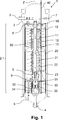
Die
Ausführungsformen der ErfindungEmbodiments of the invention
In der
Der Druckbehälter
Innerhalb des Druckbehälters
Die Führung des Gasgemischs durch die Katalysatorbetten
Die Katalysatorbetten
In dem ersten Wärmetauscher
Bei dem Reaktor
Zudem kann die in dem Reaktor entstehende Reaktionswärme zum Vorwärmen des in den Druckbehälter
Die Ausgestaltung des dritten Wärmetauschers
Insofern ist es möglich, ein Gasgemisch mit verringerter Temperatur in den Einlass
Der Druckbehälter
Ein dritter Steuereinlass
Insofern kann bei dem Reaktor
Der Reaktor
Bei dem Reaktor
Mit dem Reaktor
Der vorstehend beschriebene Reaktor
BezugszeichenlisteLIST OF REFERENCE NUMBERS
- 11
- Reaktor reactor
- 22
- Druckbehälter pressure vessel
- 2.12.1
- Reaktionsbereich reaction region
- 33
- Einlass inlet
- 44
- Auslass outlet
- 55
- Rohr pipe
- 66
- erster Steuereinlass first tax entrance
- 77
- zweiter Steuereinlass second tax inlet
- 88th
- dritter Steuereinlass third control inlet
- 99
- Bypass-Leitung Bypass line
- 1010
- erstes Katalysatorbett first catalyst bed
- 1111
- erster Wärmetauscher first heat exchanger
- 1212
- Wärmetauscherrohr heat exchanger tube
- 1313
- Umlenkblech baffle
- 2020
- zweites Katalysatorbett second catalyst bed
- 2121
- zweiter Wärmetauscher second heat exchanger
- 2222
- Wärmetauscherrohr heat exchanger tube
- 2323
- Umlenkblech baffle
- 3030
- drittes Katalysatorbett third catalyst bed
- 3131
- dritter Wärmetauscher third heat exchanger
- 3232
- U-Rohr U-tube
- 3333
- Umlenkblech baffle
- 3434
- Mantelraum shell space
- 4040
- Temperatursensor temperature sensor
- 5050
- Zentralrohr central tube
- 6060
- Einsatz commitment
- ZZ
- Zylinderachse cylinder axis
ZITATE ENTHALTEN IN DER BESCHREIBUNG QUOTES INCLUDE IN THE DESCRIPTION
Diese Liste der vom Anmelder aufgeführten Dokumente wurde automatisiert erzeugt und ist ausschließlich zur besseren Information des Lesers aufgenommen. Die Liste ist nicht Bestandteil der deutschen Patent- bzw. Gebrauchsmusteranmeldung. Das DPMA übernimmt keinerlei Haftung für etwaige Fehler oder Auslassungen.This list of the documents listed by the applicant has been generated automatically and is included solely for the better information of the reader. The list is not part of the German patent or utility model application. The DPMA assumes no liability for any errors or omissions.
Zitierte PatentliteraturCited patent literature
- DE 102006061847 A1 [0002] DE 102006061847 A1 [0002]
Claims (10)
Priority Applications (4)
| Application Number | Priority Date | Filing Date | Title |
|---|---|---|---|
| DE102015114201.5A DE102015114201A1 (en) | 2015-08-26 | 2015-08-26 | Reactor and process for the catalytic conversion of a gas mixture |
| DK16757882.2T DK3341113T3 (en) | 2015-08-26 | 2016-08-26 | Reactor and process for the catalytic conversion of a gas mixture |
| PCT/EP2016/070194 WO2017032880A1 (en) | 2015-08-26 | 2016-08-26 | Reactor and method for catalytic conversion of a gas mixture |
| EP16757882.2A EP3341113B1 (en) | 2015-08-26 | 2016-08-26 | Reactor and method for catalytic conversion of a gas mixture |
Applications Claiming Priority (1)
| Application Number | Priority Date | Filing Date | Title |
|---|---|---|---|
| DE102015114201.5A DE102015114201A1 (en) | 2015-08-26 | 2015-08-26 | Reactor and process for the catalytic conversion of a gas mixture |
Publications (1)
| Publication Number | Publication Date |
|---|---|
| DE102015114201A1 true DE102015114201A1 (en) | 2017-03-02 |
Family
ID=56842818
Family Applications (1)
| Application Number | Title | Priority Date | Filing Date |
|---|---|---|---|
| DE102015114201.5A Ceased DE102015114201A1 (en) | 2015-08-26 | 2015-08-26 | Reactor and process for the catalytic conversion of a gas mixture |
Country Status (4)
| Country | Link |
|---|---|
| EP (1) | EP3341113B1 (en) |
| DE (1) | DE102015114201A1 (en) |
| DK (1) | DK3341113T3 (en) |
| WO (1) | WO2017032880A1 (en) |
Cited By (3)
| Publication number | Priority date | Publication date | Assignee | Title |
|---|---|---|---|---|
| CN107055570A (en) * | 2017-03-21 | 2017-08-18 | 武汉金中石化工程有限公司 | Low-pressure synthetic ammonia equipment and low-pressure synthetic ammonia method |
| WO2019149434A1 (en) * | 2018-02-01 | 2019-08-08 | Siemens Aktiengesellschaft | Plug flow reactor and method for operating a plug flow reactor |
| WO2024088648A1 (en) | 2022-10-27 | 2024-05-02 | Casale Sa | Chemical reactor with a heat exchanger |
Citations (5)
| Publication number | Priority date | Publication date | Assignee | Title |
|---|---|---|---|---|
| EP0222069A2 (en) * | 1985-09-13 | 1987-05-20 | Ammonia Casale S.A. | Converter for heterogeneous synthesis more particularly for ammonia, methanol and higher alcohols |
| DE69732781T2 (en) * | 1997-11-28 | 2006-02-02 | Ammonia Casale S.A. | Process for the in-situ modernization of a heterogeneous exothermic synthesis reactor |
| DE102006061847A1 (en) | 2006-12-21 | 2008-06-26 | Uhde Gmbh | Ammonia converter comprises a radially flowed-through catalyst bed, which concentrically surrounds a heat exchanger, an external- and/or an internal annular space and a main flow direction formed by the catalyst bed |
| EP2610001A1 (en) * | 2011-12-27 | 2013-07-03 | Ammonia Casale S.A. | Adiabatic multi-bed catalytic converter with inter-bed cooling and a related process |
| EP2759338A1 (en) * | 2013-01-29 | 2014-07-30 | Ammonia Casale S.A. | Adiabatic multi-bed catalytic converter with inter-bed cooling |
Family Cites Families (3)
| Publication number | Priority date | Publication date | Assignee | Title |
|---|---|---|---|---|
| DE1957696A1 (en) * | 1969-11-17 | 1971-05-19 | Lentia Gmbh | Ammonia synthesis catalytic reactor |
| AT306745B (en) * | 1971-05-24 | 1973-04-25 | Chemie Linz Ag | Device for performing high-pressure syntheses, for example ammonia synthesis |
| EP0332757A3 (en) * | 1987-12-24 | 1990-03-07 | Ammonia Casale S.A. | Converters for heterogeneous catalytic synthesis, particularly for ammonia and methanol, under pressure |
-
2015
- 2015-08-26 DE DE102015114201.5A patent/DE102015114201A1/en not_active Ceased
-
2016
- 2016-08-26 EP EP16757882.2A patent/EP3341113B1/en active Active
- 2016-08-26 WO PCT/EP2016/070194 patent/WO2017032880A1/en not_active Ceased
- 2016-08-26 DK DK16757882.2T patent/DK3341113T3/en active
Patent Citations (5)
| Publication number | Priority date | Publication date | Assignee | Title |
|---|---|---|---|---|
| EP0222069A2 (en) * | 1985-09-13 | 1987-05-20 | Ammonia Casale S.A. | Converter for heterogeneous synthesis more particularly for ammonia, methanol and higher alcohols |
| DE69732781T2 (en) * | 1997-11-28 | 2006-02-02 | Ammonia Casale S.A. | Process for the in-situ modernization of a heterogeneous exothermic synthesis reactor |
| DE102006061847A1 (en) | 2006-12-21 | 2008-06-26 | Uhde Gmbh | Ammonia converter comprises a radially flowed-through catalyst bed, which concentrically surrounds a heat exchanger, an external- and/or an internal annular space and a main flow direction formed by the catalyst bed |
| EP2610001A1 (en) * | 2011-12-27 | 2013-07-03 | Ammonia Casale S.A. | Adiabatic multi-bed catalytic converter with inter-bed cooling and a related process |
| EP2759338A1 (en) * | 2013-01-29 | 2014-07-30 | Ammonia Casale S.A. | Adiabatic multi-bed catalytic converter with inter-bed cooling |
Cited By (4)
| Publication number | Priority date | Publication date | Assignee | Title |
|---|---|---|---|---|
| CN107055570A (en) * | 2017-03-21 | 2017-08-18 | 武汉金中石化工程有限公司 | Low-pressure synthetic ammonia equipment and low-pressure synthetic ammonia method |
| CN107055570B (en) * | 2017-03-21 | 2023-07-25 | 武汉金中石化工程有限公司 | Low-pressure ammonia synthesis equipment and low-pressure ammonia synthesis method |
| WO2019149434A1 (en) * | 2018-02-01 | 2019-08-08 | Siemens Aktiengesellschaft | Plug flow reactor and method for operating a plug flow reactor |
| WO2024088648A1 (en) | 2022-10-27 | 2024-05-02 | Casale Sa | Chemical reactor with a heat exchanger |
Also Published As
| Publication number | Publication date |
|---|---|
| WO2017032880A1 (en) | 2017-03-02 |
| EP3341113A1 (en) | 2018-07-04 |
| DK3341113T3 (en) | 2020-07-13 |
| EP3341113B1 (en) | 2020-04-08 |
Similar Documents
| Publication | Publication Date | Title |
|---|---|---|
| DE2201528C2 (en) | Reaction apparatus for carrying out exothermic and endothermic catalytic processes with radial flow of the heat exchange medium | |
| EP0864830B1 (en) | Heat exchanger with U-shaped tubes | |
| DE2513499C2 (en) | ||
| DE2815856A1 (en) | REACTOR | |
| DD297697A5 (en) | ROHRBUENDEL-HEAT EXCHANGER | |
| DE102018113735A1 (en) | Process, tube bundle reactor and reactor system for carrying out catalytic gas phase reactions | |
| EP1681091B1 (en) | Reactor with tube bundle for carrying out exothermal or endothermal reactions | |
| DD262420A1 (en) | REACTOR FOR THE AMMONIA SYNTHESIS | |
| EP3536763A1 (en) | Quench system | |
| DE69009267T2 (en) | Combined heat exchange system for ammonia synthesis reaction streams. | |
| DE69105986T2 (en) | AMMONIA SYNTHESIS APPARATUS. | |
| EP3341113B1 (en) | Reactor and method for catalytic conversion of a gas mixture | |
| EP3497392B1 (en) | Use of a plate heat exchanger and of a synthesis device, and method for producing a product | |
| WO2019233674A1 (en) | Method and reactor system for carrying out catalytic gas phase reactions | |
| DE3819453A1 (en) | DEVICE FOR CARRYING OUT EXOTHERMAL, CATALYTIC GAS REACTIONS FOR AMMONIA OR METHANOL SYNTHESIS | |
| DE2803945C2 (en) | Device for increasing the ammonia build-up during catalytic ammonia synthesis | |
| DE2903644C2 (en) | Heat exchanger for a gas-cooled nuclear reactor plant | |
| DE10102963C1 (en) | Equalizing pressure between inside of hot gas guiding channel and annular chamber in coal gasifier comprises forming sliding site gas-tight with respect to hot gas fed into hot gas guiding channel | |
| EP0369556B1 (en) | Process and apparatus for indirectly heating a process gas stream in a reaction space for an endothermal reaction | |
| DE2936199C2 (en) | Process for superheating gaseous media | |
| DE1217934B (en) | Method and device for intensifying the formation of ammonia in catalytic ammonia synthesis | |
| EP0345505A2 (en) | Apparatus for carrying out exothermal, catalytical gas reactions for ammoniac or methanol synthesis | |
| DE1244730B (en) | Spherical reactor with a catalyst bed for carrying out exothermic gas reactions at elevated temperatures and pressures, especially for ammonia or methanol synthesis | |
| DE102016221967A1 (en) | Process for the production of ammonia and ammonia synthesis converter | |
| DE541608C (en) | Apparatus for the synthetic production of ammonia |
Legal Events
| Date | Code | Title | Description |
|---|---|---|---|
| R012 | Request for examination validly filed | ||
| R081 | Change of applicant/patentee |
Owner name: THYSSENKRUPP AG, DE Free format text: FORMER OWNERS: THYSSENKRUPP AG, 45143 ESSEN, DE; THYSSENKRUPP INDUSTRIAL SOLUTIONS AG, 45143 ESSEN, DE Owner name: THYSSENKRUPP INDUSTRIAL SOLUTIONS AG, DE Free format text: FORMER OWNERS: THYSSENKRUPP AG, 45143 ESSEN, DE; THYSSENKRUPP INDUSTRIAL SOLUTIONS AG, 45143 ESSEN, DE |
|
| R082 | Change of representative |
Representative=s name: KUTZENBERGER WOLFF & PARTNER PATENTANWALTSPART, DE |
|
| R081 | Change of applicant/patentee |
Owner name: THYSSENKRUPP INDUSTRIAL SOLUTIONS AG, DE Free format text: FORMER OWNERS: THYSSENKRUPP AG, 45143 ESSEN, DE; THYSSENKRUPP INDUSTRIAL SOLUTIONS AG, 45143 ESSEN, DE Owner name: THYSSENKRUPP AG, DE Free format text: FORMER OWNERS: THYSSENKRUPP AG, 45143 ESSEN, DE; THYSSENKRUPP INDUSTRIAL SOLUTIONS AG, 45143 ESSEN, DE |
|
| R082 | Change of representative |
Representative=s name: KUTZENBERGER WOLFF & PARTNER PATENTANWALTSPART, DE |
|
| R081 | Change of applicant/patentee |
Owner name: THYSSENKRUPP AG, DE Free format text: FORMER OWNERS: THYSSENKRUPP AG, 45143 ESSEN, DE; THYSSENKRUPP INDUSTRIAL SOLUTIONS AG, 45143 ESSEN, DE Owner name: THYSSENKRUPP INDUSTRIAL SOLUTIONS AG, DE Free format text: FORMER OWNERS: THYSSENKRUPP AG, 45143 ESSEN, DE; THYSSENKRUPP INDUSTRIAL SOLUTIONS AG, 45143 ESSEN, DE |
|
| R082 | Change of representative |
Representative=s name: KUTZENBERGER WOLFF & PARTNER PATENTANWALTSPART, DE |
|
| R002 | Refusal decision in examination/registration proceedings | ||
| R003 | Refusal decision now final |