DE102015114017B4 - Control valve - Google Patents
Control valve Download PDFInfo
- Publication number
- DE102015114017B4 DE102015114017B4 DE102015114017.9A DE102015114017A DE102015114017B4 DE 102015114017 B4 DE102015114017 B4 DE 102015114017B4 DE 102015114017 A DE102015114017 A DE 102015114017A DE 102015114017 B4 DE102015114017 B4 DE 102015114017B4
- Authority
- DE
- Germany
- Prior art keywords
- valve
- sleeve
- valve rod
- elements
- control valve
- Prior art date
- Legal status (The legal status is an assumption and is not a legal conclusion. Google has not performed a legal analysis and makes no representation as to the accuracy of the status listed.)
- Active
Links
Images


Classifications
-
- F—MECHANICAL ENGINEERING; LIGHTING; HEATING; WEAPONS; BLASTING
- F16—ENGINEERING ELEMENTS AND UNITS; GENERAL MEASURES FOR PRODUCING AND MAINTAINING EFFECTIVE FUNCTIONING OF MACHINES OR INSTALLATIONS; THERMAL INSULATION IN GENERAL
- F16K—VALVES; TAPS; COCKS; ACTUATING-FLOATS; DEVICES FOR VENTING OR AERATING
- F16K1/00—Lift valves or globe valves, i.e. cut-off apparatus with closure members having at least a component of their opening and closing motion perpendicular to the closing faces
- F16K1/32—Details
- F16K1/48—Attaching valve members to screw-spindles
-
- F—MECHANICAL ENGINEERING; LIGHTING; HEATING; WEAPONS; BLASTING
- F16—ENGINEERING ELEMENTS AND UNITS; GENERAL MEASURES FOR PRODUCING AND MAINTAINING EFFECTIVE FUNCTIONING OF MACHINES OR INSTALLATIONS; THERMAL INSULATION IN GENERAL
- F16K—VALVES; TAPS; COCKS; ACTUATING-FLOATS; DEVICES FOR VENTING OR AERATING
- F16K11/00—Multiple-way valves, e.g. mixing valves; Pipe fittings incorporating such valves
- F16K11/02—Multiple-way valves, e.g. mixing valves; Pipe fittings incorporating such valves with all movable sealing faces moving as one unit
- F16K11/04—Multiple-way valves, e.g. mixing valves; Pipe fittings incorporating such valves with all movable sealing faces moving as one unit comprising only lift valves
- F16K11/044—Multiple-way valves, e.g. mixing valves; Pipe fittings incorporating such valves with all movable sealing faces moving as one unit comprising only lift valves with movable valve members positioned between valve seats
-
- F—MECHANICAL ENGINEERING; LIGHTING; HEATING; WEAPONS; BLASTING
- F16—ENGINEERING ELEMENTS AND UNITS; GENERAL MEASURES FOR PRODUCING AND MAINTAINING EFFECTIVE FUNCTIONING OF MACHINES OR INSTALLATIONS; THERMAL INSULATION IN GENERAL
- F16K—VALVES; TAPS; COCKS; ACTUATING-FLOATS; DEVICES FOR VENTING OR AERATING
- F16K11/00—Multiple-way valves, e.g. mixing valves; Pipe fittings incorporating such valves
- F16K11/02—Multiple-way valves, e.g. mixing valves; Pipe fittings incorporating such valves with all movable sealing faces moving as one unit
- F16K11/04—Multiple-way valves, e.g. mixing valves; Pipe fittings incorporating such valves with all movable sealing faces moving as one unit comprising only lift valves
- F16K11/048—Multiple-way valves, e.g. mixing valves; Pipe fittings incorporating such valves with all movable sealing faces moving as one unit comprising only lift valves with valve seats positioned between movable valve members
Abstract
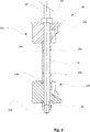
Stellventil umfassend ein Stellelement (10, 40), mit einer Ventilstange (26) und mindestens zwei mit der Ventilstange (26) verbundene Ventilelemente (12a, 12b), wobei zwischen den Ventilelementen (12a, 12b) wenigstens eine Hülse (14a, 14b, 16) vorgesehen ist, wobei die Ventilstange (26) in der Hülse (14a, 14b, 16) geführt ist, wobei die Hülse (14a, 14b. 16) und die Ventilelemente (12a, 12b) je eine zugeordnete Dichtfläche besitzen, dadurch gekennzeichnet, dass die zugewandten Enden von Hülse (14a, 14b, 16) und Ventilelement (12a, 12b) derart ausgebildet sind, dass sich wenigstens eine Formschlussstruktur (18a, 18b) ergibt, die in Umfangsrichtung die Hülse (14a, 14b, 16) und das Ventilelement (12a, 12b) formschlüssig verbindet und dass die Ventilstange (26) einen Abschnitt mit einem Kantprofil aufweist, der im montierten Zustand axial aus der von der Hülse (14a, 14b) entfernt gelegenen Seite des Ventilelements (12b) herausragt und ferner eine Fixierhülse (30) vorgesehen ist, die Formschlussstrukturen (18a, 18b) aufweist, die mit dem Stellelement (40) zusammenwirken, so dass dieses formschlüssig in Umfangrichtung festgelegt ist, wobei die Fixierhülse (30) eine zum Kantprofil der Ventilstange (26) korrespondierende Aufnahmestruktur zur in Umfangsrichtung formschlüssigen Aufnahme der Ventilstange (26) aufweist.Control valve comprising an actuating element (10, 40), having a valve rod (26) and at least two valve elements (12a, 12b) connected to the valve rod (26), wherein at least one sleeve (14a, 14b, 14a, 12b) between the valve elements (12a, 12b) 16) is provided, wherein the valve rod (26) in the sleeve (14a, 14b, 16) is guided, wherein the sleeve (14a, 14b, 16) and the valve elements (12a, 12b) each have an associated sealing surface, characterized in that the facing ends of the sleeve (14a, 14b, 16) and valve element (12a, 12b) are formed such that at least one form-fit structure (18a, 18b) results in the circumferential direction of the sleeve (14a, 14b, 16) and the valve element (12a, 12b) positively connects and that the valve rod (26) has a portion with a Kant profile, which protrudes axially in the mounted state of the sleeve (14a, 14b) side of the valve element (12b) and further a Fixing sleeve (30) is provided, d The form-fitting structures (18a, 18b) which cooperate with the adjusting element (40) so that it is fixed in the circumferential direction, wherein the fixing sleeve (30) to the edge profile of the valve rod (26) corresponding receiving structure for circumferentially positive reception of the valve stem (26).
Description
Die Erfindung betrifft ein Stellventil gemäß dem Oberbegriff des Anspruchs 1.The invention relates to a control valve according to the preamble of claim 1.
Die
Die
Die
Es ist Aufgabe der Erfindung, eine vereinfachte Ausgestaltung eines Mehrsitzventils mit mindestens zwei Ventilsitzen mit einer hohen Leckageklasse anzugeben.It is an object of the invention to provide a simplified embodiment of a multi-seat valve with at least two valve seats with a high leakage class.
Diese Aufgabe wird durch die kennzeichnenden Merkmale des Anspruchs 1 in Verbindung mit seinen Oberbegriffsmerkmalen gelöst.This object is achieved by the characterizing features of claim 1 in conjunction with its preamble features.
Die Unteransprüche bilden vorteilhafte Weiterbildungen der Erfindung.The dependent claims form advantageous developments of the invention.
In bekannter Weise umfasst ein Stellventil ein Stellelement mit einer Ventilstange und mehrere mit der Ventilstange verbundene Ventilelemente, wobei zur Beabstandung der beiden Ventilelemente zueinander zwischen den Ventilelementen wenigstens eine Hülse vorgesehen ist. Die Ventilelemente wirken je mit einem Ventilsitz zur Steuerung des Fluidstroms durch das Stellventil zusammen. Die Ventilstange ist in der Hülse geführt, wobei die Hülse und die Ventilelemente je eine einander zugeordnete Dichtfläche besitzen.In known manner, a control valve comprises an actuating element with a valve rod and a plurality of valve elements connected to the valve rod, wherein at least one sleeve is provided for spacing the two valve elements to each other between the valve elements. The valve elements each cooperate with a valve seat for controlling the fluid flow through the control valve. The valve rod is guided in the sleeve, wherein the sleeve and the valve elements each have an associated sealing surface.
Erfindungsgemäß sind die zugewandten Enden von Hülse und Ventilelement derart ausgebildet, dass sich wenigstens eine Formschlussstruktur ergibt, die in Umfangsrichtung die Hülse und das Ventilelement formschlüssig verbindet. Durch eine baueinheitliche Anformung der Formschlussstrukturen an das Ventilelement und die Hülse kann eine Vereinfachung des Aufbaus erzielt werden.According to the invention, the facing ends of the sleeve and the valve element are designed such that at least one positive locking structure results, which connects the sleeve and the valve element in a form-fitting manner in the circumferential direction. By a uniform construction of the form-fitting structures of the valve element and the sleeve simplification of the structure can be achieved.
Vorzugsweise sind die korrespondierenden Formschlussstrukturen an ihren zugewandten Enden derart angeordnet, dass sich diese an einem Niveau vollumlaufend an einer Berührfläche berühren also einen im Wesentlichen planen Flächenabschnitt bilden und eine umfänglich geschlossene Dichtfläche bilden. Auf diese Weise kann allein über die ohnehin zur Fixierung der Ventilelemente eingebrachte Spannkraft die Abdichtung des Übergangs zwischen Hülse und Ventilelement erfolgen, so dass eine äußerst geringe Leckage in den Innenraum der Hülse zugelassen wird.Preferably, the corresponding interlocking structures are arranged at their facing ends such that they touch at a level fully rotating on a contact surface thus form a substantially planar surface portion and form a circumferentially closed sealing surface. In this way, the sealing of the transition between the sleeve and the valve element can take place solely via the clamping force introduced anyway for fixing the valve elements, so that an extremely small leakage into the interior of the sleeve is permitted.
Die wenigstens eine Hülse kann lösbar oder baueinheitlich am Ventilelement angeordnet sein.The at least one sleeve can be arranged detachably or structurally on the valve element.
Die Ventilelemente können vorzugsweise eine axiale Ausnehmung aufweisen, in welche an die Hülse angeformte Formschlussstrukturen eingreifen.The valve elements may preferably have an axial recess, in which engage with the sleeve molded form-fitting structures.
Erfindungsgemäß weist die Ventilstange einen Abschnitt mit einem Kantprofil auf. Dieses Kantprofil überragt im montierten Zustand axial aus der von der Hülse entfernt gelegenen Seite das Ventilelement, So kann zur Montage ferner eine weitere Hülse, Fixierhülse, vorgesehen sein, die Formschlussstrukturen aufweist, die mit dem Ventilelement zusammenwirken, so dass dieses formschlüssig in Umfangsrichtung festgelegt ist. Die Fixierhülse weist zudem eine zum Kantprofil der Ventilstange korrespondierende Aufnahmestruktur zur in Umfangsrichtung formschlüssigen Aufnahme der Ventilstange auf. Dies sorgt für eine Drehsicherung des Ventilelements gegenüber der Ventilstange. Die Ventilstange weist insbesondere an ihrem Ende ein Gewinde auf, auf welches eine Mutter zur Aufbringung der Spannkraft aufschraubbar ist.According to the invention, the valve rod has a section with an edge profile. In the mounted state, this edge profile projects axially beyond the valve element from the side remote from the sleeve. Thus, a further sleeve, fixing sleeve, can be provided for mounting, which has positive locking structures which interact with the valve element so that it is fixed in the circumferential direction in a form-fitting manner , The fixing sleeve also has a receiving profile corresponding to the edge profile of the valve rod for receiving the valve rod in a form-locking manner in the circumferential direction. This ensures a rotation of the valve element against the valve stem. The valve rod has, in particular at its end a thread on which a nut for applying the clamping force can be screwed.
Die Dichthülse kann an ihrem in Axialrichtung von dem Ventilelement beabstandeten Ende wenigstens eine Einkerbung aufweisen, in welche an eine Zwischenscheibe angeformte Formschlussnasen eingreifen können. Dadurch erfolgt eine verbesserte Rückdrehsicherung der Mutter.The sealing sleeve may have at least one notch in its axial direction away from the valve element end, in which an intermediate disc molded form-locking lugs can intervene. This results in an improved reverse rotation of the mother.
Bevorzugt kann vorgesehen sein, dass die Formschlussstruktur gebildet ist, indem ein axialer Versatz an der Hülse vorgesehen ist, der in einen komplementären axialen Versatz am Stellelement eingreift. Der Versatz ist insbesondere derart gestaltet, dass Hülse und Ventilelement, die im Übergangsbereich denselben Außendurchmesser haben, Wandbereiche derart ausgenommen sind, dass sich radial innen an der Mantelfläche eine in Umfangsrichtung geschlossene Dichtfläche ergibt, Die Formschlussstrukturen sind also radial von der zentralen Ausnehmung der Hülse beabstandet angeordnet.Preferably, it can be provided that the form-fitting structure is formed by an axial offset is provided on the sleeve, which engages in a complementary axial offset on the adjusting element. The offset is in particular designed such that sleeve and valve element, which have the same outer diameter in the transition region, wall areas are excluded such that radially inwardly on the lateral surface a circumferentially closed sealing surface results, the interlocking structures are thus radially spaced from the central recess of the sleeve arranged.
Vorzugsweise sind also die Bereiche des axialen Versatzes im Querschnitt kreissegmentartig ausgestaltet. Durch die gerundete Außenfläche wird ein ideales Strömungsverhalten erreicht, wobei durch die in Richtung radial nach innen durch eine Sekante begrenzte Formschlussstruktur eine ausreichend große umfänglich durchgängige Dichtfläche bereitgestellt wird.Preferably, therefore, the regions of the axial offset in cross-section are configured like a circle segment. Due to the rounded outer surface, an ideal flow behavior is achieved, wherein a sufficiently large circumferentially continuous sealing surface is provided by the radially inwardly limited by a secant form-fitting structure.
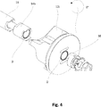
Gemäß einer vorteilhaften Weiterbildung der Erfindung weist ein Ventilelement an seinem in Axialrichtung gesehenen oberen und unteren Ende Formschlussstrukturen auf. Die oberen und unteren Formschlussstrukturen sind so ausgebildet, dass ein identisches Gegenstück in beide Formschlussstrukturen drehsichernd und abdichtend eingreifen kann. Dadurch wird eine hohe Flexibilität in der Anwendung der Ventilelemente geschaffen. So können mit denselben Ventilelementen sowohl Verteiler- als auch Mischeranordnungen realisiert werden.According to an advantageous development of the invention, a valve element has positively locking structures on its upper and lower ends, which are viewed in the axial direction. The upper and lower interlocking structures are designed so that an identical counterpart can engage in a rotationally locking and sealing manner in both interlocking structures. This creates a high degree of flexibility in the application of the valve elements. Thus, both distributor and mixer arrangements can be realized with the same valve elements.
So kann beispielsweise eine mit Formschlussstrukturen versehene Abstandshülse sowohl mit der Oberseite als auch mit der Unterseite des Ventilelements verbunden werden.Thus, for example, provided with positive locking structures spacer sleeve can be connected to both the top and with the bottom of the valve element.
An der dem Steuerbereich abgewandten Seite des Ventilelements (Oberseite) kann die Formschlussstruktur insbesondere in Form einer Senkung ausgebildet sein, in welche an der Abstandshülse angeformte Formschlussnasen eingreifen können. Erfindungsgemäß besteht, insbesondere innerhalb der Senkungen, eine Kreisringfläche, deren radiale Ausdehnung derart bemessen ist, dass sie eine Abdichtung zulässt.On the side of the valve element (upper side) facing away from the control region, the form-fitting structure can be designed in particular in the form of a countersink, into which form-locking noses formed on the spacer sleeve can engage. According to the invention consists, in particular within the subsidence, an annular surface whose radial extent is dimensioned such that it allows a seal.
Auf diese Weise kann ein einer einfachen und einer hohen Leckageanforderung gerecht werdendes Stellventil angegeben werden.In this way, a simple and a high leakage requirement expectant expectant control valve can be specified.
Weitere Vorteile, Merkmale und Anwendungsmöglichkeiten der vorliegenden Erfindung ergeben sich aus der nachfolgenden Beschreibung in Verbindung mit den in den Zeichnungen dargestellten Ausführungsbeispielen.Further advantages, features and possible applications of the present invention will become apparent from the following description in conjunction with the embodiments illustrated in the drawings.
In der Beschreibung, in den Ansprüchen und in der Zeichnung werden die in der unten aufgeführten Liste der Bezugszeichen verwendeten Begriffe und zugeordneten Bezugszeichen verwendet. In der Zeichnung bedeutet:In the description, the claims, and the drawing, the terms and associated reference numerals used in the list of reference numerals below are used. In the drawing:
Ferner ist eine Fixierhülse
Durch die Erfindung wird ein einfaches, hohen Leckageanforderungen gerecht werdendes, und flexibles Stellventil geschaffen.The invention provides a simple, high leakage requirements expectant, and flexible control valve is created.
BezugszeichenlisteLIST OF REFERENCE NUMBERS
- 1010
- Stellelementactuator
- 12a, 12b12a, 12b
- Ventilelementvalve element
- 14a, 14b14a, 14b
- FormschlusshülseForm-fitting sleeve
- 1616
- Abstandshülsespacer
- 18a, 18b18a, 18b
- FormschlussstrukturenForm-fitting structures
- 2020
- Oberseitetop
- 20a, 20b20a, 20b
- Oberseitetop
- 22a, 22b22a, 22b
- Senkungenreductions
- 2424
- Anlageelementcontact element
- 2626
- Ventilstangevalve rod
- 2828
- Muttermother
- 3030
- Fixierhülsefixing sleeve
- 3232
- Beilegscheibewasher
- 4040
- Stellelementactuator
- 4242
- Senkungenreductions
- DD
- Dichtflächesealing surface
Claims (5)
Priority Applications (2)
| Application Number | Priority Date | Filing Date | Title |
|---|---|---|---|
| DE102015114017.9A DE102015114017B4 (en) | 2015-08-24 | 2015-08-24 | Control valve |
| CN201620927922.1U CN206468827U (en) | 2015-08-24 | 2016-08-23 | Regulating valve |
Applications Claiming Priority (1)
| Application Number | Priority Date | Filing Date | Title |
|---|---|---|---|
| DE102015114017.9A DE102015114017B4 (en) | 2015-08-24 | 2015-08-24 | Control valve |
Publications (2)
| Publication Number | Publication Date |
|---|---|
| DE102015114017A1 DE102015114017A1 (en) | 2017-03-02 |
| DE102015114017B4 true DE102015114017B4 (en) | 2018-02-08 |
Family
ID=58011064
Family Applications (1)
| Application Number | Title | Priority Date | Filing Date |
|---|---|---|---|
| DE102015114017.9A Active DE102015114017B4 (en) | 2015-08-24 | 2015-08-24 | Control valve |
Country Status (2)
| Country | Link |
|---|---|
| CN (1) | CN206468827U (en) |
| DE (1) | DE102015114017B4 (en) |
Families Citing this family (1)
| Publication number | Priority date | Publication date | Assignee | Title |
|---|---|---|---|---|
| WO2020116322A1 (en) * | 2018-12-05 | 2020-06-11 | 株式会社不二工機 | Valve device |
Citations (4)
| Publication number | Priority date | Publication date | Assignee | Title |
|---|---|---|---|---|
| US1851016A (en) * | 1929-12-19 | 1932-03-29 | John J Skelly | Valve |
| DE1070896B (en) * | 1959-12-10 | |||
| EP2397727B1 (en) * | 2010-06-21 | 2012-11-28 | Krones AG | Multi-part valve disc |
| US20140083515A1 (en) * | 2012-09-27 | 2014-03-27 | Emerson Process Management Regulator Technologies, Inc. | Slam shut safety device having disc anti-rotation |
-
2015
- 2015-08-24 DE DE102015114017.9A patent/DE102015114017B4/en active Active
-
2016
- 2016-08-23 CN CN201620927922.1U patent/CN206468827U/en active Active
Patent Citations (4)
| Publication number | Priority date | Publication date | Assignee | Title |
|---|---|---|---|---|
| DE1070896B (en) * | 1959-12-10 | |||
| US1851016A (en) * | 1929-12-19 | 1932-03-29 | John J Skelly | Valve |
| EP2397727B1 (en) * | 2010-06-21 | 2012-11-28 | Krones AG | Multi-part valve disc |
| US20140083515A1 (en) * | 2012-09-27 | 2014-03-27 | Emerson Process Management Regulator Technologies, Inc. | Slam shut safety device having disc anti-rotation |
Also Published As
| Publication number | Publication date |
|---|---|
| CN206468827U (en) | 2017-09-05 |
| DE102015114017A1 (en) | 2017-03-02 |
Similar Documents
| Publication | Publication Date | Title |
|---|---|---|
| DE4121524C2 (en) | Screw connection | |
| EP3439774B1 (en) | Mixing shaft | |
| DE2453635A1 (en) | PRELOADED DIFFERENTIAL DOUBLE NUT | |
| DE10034748A1 (en) | Detachable connecting element for a vehicle wheel, with a screw part and a support ring | |
| WO2010028746A1 (en) | Brake disk having a brake disk pot | |
| EP3132146B1 (en) | Fastening device | |
| DE102011078256A1 (en) | Screw and method of making a screw thread | |
| EP3601865B1 (en) | Pipe coupling | |
| DE10220233A1 (en) | Mother and process for its manufacture | |
| EP3105462B1 (en) | Machine element | |
| EP3538776B1 (en) | Headlamp with a housing and a set screw | |
| DE19632917B4 (en) | Bremsenjustiermechanismus | |
| WO2013093900A1 (en) | Jaw or claw-shaped gap seal | |
| DE2462474A1 (en) | SPRINKLER HEAD FOR A SPRINKLER SYSTEM | |
| DE102015114017B4 (en) | Control valve | |
| WO2011110457A1 (en) | Annular, axial securing element | |
| DE102008001381B3 (en) | unit | |
| CH703184A1 (en) | Spherical plain bearings. | |
| DE102013201073A1 (en) | Hollow wheel for planetary gear of wind turbine, has truncated cone-or funnel-shaped connecting surface in area of its two front sides, which extends in circumferential direction for coupling with housing section of planetary gear | |
| EP2143961B1 (en) | Bore sealing arrangement | |
| DE102016219889A1 (en) | seal | |
| DE102016216087B4 (en) | Actuator, in particular a rear axle steering | |
| WO2003011672A1 (en) | Device for locking the final positions of moving switch points | |
| DE102012015504B4 (en) | Component with screw-in section and assembly equipped with it | |
| DE102019218402B4 (en) | Spring dome for a hydraulic valve and hydraulic valve with such a spring dome |
Legal Events
| Date | Code | Title | Description |
|---|---|---|---|
| R012 | Request for examination validly filed | ||
| R016 | Response to examination communication | ||
| R018 | Grant decision by examination section/examining division | ||
| R020 | Patent grant now final |