DE102014216488B4 - MOTOR DRIVEN COMPRESSOR - Google Patents

MOTOR DRIVEN COMPRESSOR Download PDF

Info

Publication number
DE102014216488B4
DE102014216488B4 DE102014216488.5A DE102014216488A DE102014216488B4 DE 102014216488 B4 DE102014216488 B4 DE 102014216488B4 DE 102014216488 A DE102014216488 A DE 102014216488A DE 102014216488 B4 DE102014216488 B4 DE 102014216488B4
Authority
DE
Germany
Prior art keywords
insulator
shield
cover
peripheral portion
motor
Prior art date
Legal status (The legal status is an assumption and is not a legal conclusion. Google has not performed a legal analysis and makes no representation as to the accuracy of the status listed.)
Active
Application number
DE102014216488.5A
Other languages
German (de)
Other versions
DE102014216488A1 (en
Inventor
Yusuke c/o K.K. TOYOTA JIDOSHOKKI Kinoshita
c/o KABUSHIKI KAISHA TOYOTA JIDOSHO Suitou Ken
Tatsushi K.K. TOYOTA JIDOSHOKKI Mori
Kazuhiro c/o K.K. TOYOTA JIDOSHOKKI Kuroki
Tatsuya c/o K.K. TOYOTA JIDOSHOKKI Koide
c/o KABUSHIKI KAISHA TOYOTA JIDOSH Yano Junya
Takuro c/o KABUSHIKI KAISHA TOYOTA JIDOS Mizuno
Current Assignee (The listed assignees may be inaccurate. Google has not performed a legal analysis and makes no representation or warranty as to the accuracy of the list.)
Toyota Industries Corp
Original Assignee
Toyota Industries Corp
Priority date (The priority date is an assumption and is not a legal conclusion. Google has not performed a legal analysis and makes no representation as to the accuracy of the date listed.)
Filing date
Publication date
Application filed by Toyota Industries Corp filed Critical Toyota Industries Corp
Publication of DE102014216488A1 publication Critical patent/DE102014216488A1/en
Application granted granted Critical
Publication of DE102014216488B4 publication Critical patent/DE102014216488B4/en
Active legal-status Critical Current
Anticipated expiration legal-status Critical

Links

Images

Classifications

    • HELECTRICITY
    • H02GENERATION; CONVERSION OR DISTRIBUTION OF ELECTRIC POWER
    • H02KDYNAMO-ELECTRIC MACHINES
    • H02K11/00Structural association of dynamo-electric machines with electric components or with devices for shielding, monitoring or protection
    • H02K11/30Structural association with control circuits or drive circuits
    • H02K11/33Drive circuits, e.g. power electronics
    • HELECTRICITY
    • H02GENERATION; CONVERSION OR DISTRIBUTION OF ELECTRIC POWER
    • H02KDYNAMO-ELECTRIC MACHINES
    • H02K11/00Structural association of dynamo-electric machines with electric components or with devices for shielding, monitoring or protection
    • H02K11/01Structural association of dynamo-electric machines with electric components or with devices for shielding, monitoring or protection for shielding from electromagnetic fields, i.e. structural association with shields
    • H02K11/014Shields associated with stationary parts, e.g. stator cores
    • H02K11/0141Shields associated with casings, enclosures or brackets
    • HELECTRICITY
    • H02GENERATION; CONVERSION OR DISTRIBUTION OF ELECTRIC POWER
    • H02KDYNAMO-ELECTRIC MACHINES
    • H02K5/00Casings; Enclosures; Supports
    • H02K5/04Casings or enclosures characterised by the shape, form or construction thereof
    • H02K5/06Cast metal casings
    • HELECTRICITY
    • H02GENERATION; CONVERSION OR DISTRIBUTION OF ELECTRIC POWER
    • H02KDYNAMO-ELECTRIC MACHINES
    • H02K5/00Casings; Enclosures; Supports
    • H02K5/04Casings or enclosures characterised by the shape, form or construction thereof
    • H02K5/10Casings or enclosures characterised by the shape, form or construction thereof with arrangements for protection from ingress, e.g. water or fingers
    • HELECTRICITY
    • H02GENERATION; CONVERSION OR DISTRIBUTION OF ELECTRIC POWER
    • H02KDYNAMO-ELECTRIC MACHINES
    • H02K5/00Casings; Enclosures; Supports
    • H02K5/04Casings or enclosures characterised by the shape, form or construction thereof
    • H02K5/22Auxiliary parts of casings not covered by groups H02K5/06-H02K5/20, e.g. shaped to form connection boxes or terminal boxes
    • H02K5/225Terminal boxes or connection arrangements

Abstract

Ein motorgetriebener Verdichter hat ein Metallgehäuse, das eine Verdichtungseinheit und einen Elektromotor aufnimmt, und eine an das Gehäuse gekoppelte Abdeckung. Die Abdeckung und das Gehäuse definieren eine Aufnahmekammer, die einen Motorantriebsschaltkreis aufnimmt, der den Elektromotor antreibt. Die Abdeckung hat einen Metallschild, das ein elektromagnetisches Geräusch blockiert, einen äußeren Isolator aus Harz, der an einer Außenseite des Schilds befestigt ist und einen äußeren Umfangsabschnitt hat, und einen inneren Isolator aus Harz, der an einer Innenseite des Schilds befestigt ist und einen äußeren Umfangsabschnitt hat. Der Schild, der äußere Isolator und der innere Isolator sind voneinander getrennt und zusammengestapelt. Der Schild ist zwischen dem äußeren Isolator und dem inneren Isolator gehalten. Der äußere Umfangsabschnitt des äußeren Isolators ist mit dem äußeren Umfangsabschnitt des inneren Isolators gefügt.

Figure DE102014216488B4_0000
A motor-driven compressor has a metal housing accommodating a compression unit and an electric motor, and a cover coupled to the housing. The cover and the housing define a receiving chamber that houses a motor drive circuit that drives the electric motor. The cover has a metal shield that blocks an electromagnetic noise, an outer insulator made of resin attached to an outer side of the shield and having an outer peripheral portion, and an inner insulator made of resin attached to an inner side of the shield and an outer one Peripheral section has. The shield, the outer insulator and the inner insulator are separated and stacked together. The shield is held between the outer insulator and the inner insulator. The outer peripheral portion of the outer insulator is joined to the outer peripheral portion of the inner insulator.
Figure DE102014216488B4_0000

Description

Die vorliegende Erfindung betrifft einen motorgetriebenen Verdichter.The present invention relates to a motor-driven compressor.

Ein motorgetriebener Verdichter hat ein Metallgehäuse, das eine Verdichtungseinheit aufnimmt, die ein Kältemittel verdichtet und abgibt, und einen Elektromotor, der die Verdichtungseinheit antreibt. Eine Abdeckung, die eine Aufnahmekammer definiert, ist an das Gehäuse gekoppelt. Die Aufnahmekammer nimmt einen Motorantriebsschaltkreis auf, der den Elektromotor antreibt.A motor-driven compressor has a metal housing that houses a compression unit that compresses and discharges a refrigerant, and an electric motor that drives the compression unit. A cover defining a receiving chamber is coupled to the housing. The receiving chamber receives a motor drive circuit that drives the electric motor.

Wenn die Abdeckung aus Metall hergestellt ist, steigt das Gesamtgewicht des motorgetriebenen Verdichters. Die Verwendung einer Harzabdeckung gestattet es, dass der motorgetriebene Verdichter leichter wird. Jedoch würde eine Harzabdeckung ein elektromagnetisches Geräusch von außerhalb des Verdichters zu dem Motorantriebsschaltkreis übertragen. Zusätzlich kann durch die Harzabdeckung ein elektromagnetisches Geräusch von dem Motorantriebsschaltkreis aus dem Verdichter ausströmen.If the cover is made of metal, the total weight of the motor-driven compressor increases. The use of a resin cover allows the motor-driven compressor to become lighter. However, a resin cover would transmit electromagnetic noise from outside the compressor to the motor drive circuit. In addition, electromagnetic noise from the motor drive circuit may leak from the compressor through the resin cover.

Entsprechend ist in der Druckschrift JP 2008 - 215236 A ein metallischer Leiter (Schild) auf einem Harzisolator gestapelt und an diesem befestigt. Ein elektromagnetisches Geräusch von außen wird durch den Leiter blockiert und zu einem Gehäuse übertragen. Dies begrenzt das elektromagnetische Geräusch, das in eine Aufnahmekammer eindringt, die einen Motorantriebsschaltkreis aufnimmt, durch den Isolator. Zusätzlich wird ein elektromagnetisches Geräusch von dem Motorantriebsschaltkreis durch den Leiter blockiert und zu dem Gehäuse übertragen. Dies begrenzt das Ausströmen von einem elektromagnetischen Geräusch von dem Motorantriebsschaltkreis nach außen durch den Isolator.Accordingly, in the document JP 2008 - 215236 A a metallic conductor (shield) stacked on a resin insulator and secured thereto. An electromagnetic noise from outside is blocked by the conductor and transmitted to a housing. This limits the electromagnetic noise entering a receiving chamber accommodating a motor drive circuit through the insulator. In addition, electromagnetic noise from the motor drive circuit is blocked by the conductor and transmitted to the housing. This limits the outflow of electromagnetic noise from the motor drive circuit to the outside through the insulator.

Wenn die äußere Oberfläche des Leiters freigelegt ist, kann die Umgebungsluft den Leiter erodieren. Somit kann ein Isolator (äußerer Isolator) an der äußeren Oberfläche des Leiters befestigt sein. Der Isolator bedeckt die äußere Oberfläche des Leiters so, dass der Leiter nicht zu der Umgebungsluft freigelegt ist. Außerdem kann ein Isolator (innerer Isolator) auf der inneren Oberfläche des Leiters gestapelt sein und daran befestigt sein, um den Motorantriebsschaltkreis von dem Leiter zu isolieren, so dass der Isolator zwischen dem Motorantriebsschaltkreis und dem Leiter angeordnet ist.When the outer surface of the conductor is exposed, the ambient air may erode the conductor. Thus, an insulator (outer insulator) may be attached to the outer surface of the conductor. The insulator covers the outer surface of the conductor so that the conductor is not exposed to the ambient air. In addition, an insulator (inner insulator) may be stacked on and fixed to the inner surface of the conductor to insulate the motor drive circuit from the conductor so that the insulator is disposed between the motor drive circuit and the conductor.

Formen kann durchgeführt werden, um eine derartige dreischichtige Abdeckung mit an den äußeren und inneren Oberflächen des Leiters befestigten Isolatoren auszubilden. Insbesondere wenn ein Leiter in einer Form angeordnet ist, wird die Form an den inneren und äußeren Seiten des Leiters mit einem geschmolzenem Harz gefüllt. Das geschmolzene Harz wird dann ausgehärtet, um Harzisolatoren auszubilden, die auf den inneren und äußeren Oberflächen des Leiters gestapelt und an diesem befestigt sind. Dies bildet die dreischichtige Abdeckung mit Isolatoren, die an den äußeren und inneren Oberflächen des Leiters befestigt sind.Shaping may be performed to form such a three-layer cover with insulators attached to the outer and inner surfaces of the conductor. In particular, when a conductor is arranged in a mold, the mold on the inner and outer sides of the conductor is filled with a molten resin. The molten resin is then cured to form resin insulators stacked and fixed to the inner and outer surfaces of the conductor. This forms the three-layer cover with insulators attached to the outer and inner surfaces of the conductor.

Wenn die Abdeckung nach dem Formen auf Raumtemperatur zurückgeführt wird, unterliegen der Leiter, der äußere Isolator und der innere Isolator einer thermischen Kontraktion. Da der lineare Ausdehnungskoeffizient des Leiters sich von dem der Isolatoren unterscheidet, unterscheidet sich der Grad der thermischen Kontraktion des Leiters von dem der Isolatoren. Das Anhaften zwischen dem Leiter und dem Isolator kann eine gleichmäßige Kontraktion von jeder Schicht behindern. Dies kann den Leiter und die Isolatoren während der thermischen Kontraktion verformen. Als Ergebnis können die gewünschte Form und Abmessungsgenauigkeit der Abdeckung nicht erhalten werden.When the cover is returned to room temperature after molding, the conductor, outer insulator and inner insulator undergo thermal contraction. Since the linear expansion coefficient of the conductor differs from that of the insulators, the degree of thermal contraction of the conductor differs from that of the insulators. The adhesion between the conductor and the insulator can hinder a uniform contraction of each layer. This can deform the conductor and insulators during thermal contraction. As a result, the desired shape and dimensional accuracy of the cover can not be obtained.

Die Druckschrift EP 2 500 516 A2 offenbart einen elektrischen Verdichter. Dieser weist eine an ein metallisches Gehäuse gekoppelte Abdeckung auf. Die Abdeckung und das Gehäuse bilden eine Aufnahmekammer aus, die einen Motorantriebsschaltkreis aufnimmt, der einen Elektromotor antreibt. Die Abdeckung hat einen Metallschild, der eine elektromagnetisches Geräusch blockiert, einen äußeren Isolator aus Harz, der an einer äußeren Seite des Schilds befestigt ist, und einen inneren Isolator aus Harz, der an einer Innenseite des Schilds befestigt ist. Der Schild ist zwischen den inneren und äußeren Isolatoren gehalten.The publication EP 2 500 516 A2 discloses an electric compressor. This has a coupled to a metallic housing cover. The cover and the housing form a receiving chamber that houses a motor drive circuit that drives an electric motor. The cover has a metal shield that blocks electromagnetic noise, a resin outer insulator attached to an outer side of the shield, and an inner resin insulator attached to an inside of the shield. The shield is held between the inner and outer insulators.

Es ist die Aufgabe der vorliegenden Offenbarung, einen motorgetriebenen Verdichter bereitzustellen, der eine Abdeckung hat, die die gewünschte Form und eine hohe Abmessungsgenauigkeit aufweist.It is the object of the present disclosure to provide a motor-driven compressor having a cover having the desired shape and a high dimensional accuracy.

Die Aufgabe der Erfindung wird durch einen Verdichter nach Anspruch 1 gelöst. Vorteilhafte Ausführungsformen werden gemäß den abhängigen Ansprüchen ausgeführt.The object of the invention is achieved by a compressor according to claim 1. Advantageous embodiments are set forth in the dependent claims.

Die vorliegende Erfindung betrifft einen motorgetriebenen Verdichter mit einem Metallgehäuse, das eine Verdichtungseinheit und einen Elektromotor aufnimmt, und einer an das Gehäuse gekoppelten Abdeckung. Die Abdeckung und das Gehäuse definieren eine Aufnahmekammer, die einen Motorantriebsschaltkreis aufnimmt, der den Elektromotor antreibt. Die Abdeckung hat einen Metallschild, der ein elektromagnetisches Geräusch blockiert, einen äußeren Harzisolator, der an einer äußeren Seite des Schilds befestigt ist und einen äußeren Umfangsabschnitt aufweist, und einen inneren Harzisolator, der an einer Innenseite des Schilds befestigt ist und einen äußeren Umfangsabschnitt hat. Der Schild, der äußere Isolator und der innere Isolator sind voneinander getrennt und zusammengestapelt. Der Schild ist zwischen dem äußeren Isolator und dem inneren Isolator gehalten. Der äußere Umfangsabschnitt des äußeren Isolators ist mit dem äußeren Umfangsabschnitt des inneren Isolators gefügt.The present invention relates to a motor-driven compressor having a metal housing accommodating a compacting unit and an electric motor and a cover coupled to the housing. The cover and the housing define a receiving chamber that houses a motor drive circuit that drives the electric motor. The cover has a metal shield that blocks electromagnetic noise, an outer resin insulator attached to an outer side of the shield and having an outer peripheral portion, and an inner resin insulator attached to an inner side of the shield and has an outer peripheral portion. The shield, the outer insulator and the inner insulator are separated and stacked together. The shield is held between the outer insulator and the inner insulator. The outer peripheral portion of the outer insulator is joined to the outer peripheral portion of the inner insulator.

Vorteile der vorliegenden Erfindung werden aus der folgenden Beschreibung deutlich, die in Zusammenhang mit den begleitenden Zeichnungen zu sehen ist, die mittels Beispiel die Grundlagen der Erfindung darstellt.Advantages of the present invention will become apparent from the following description, taken in conjunction with the accompanying drawings, illustrating by way of example the principles of the invention.

Figurenlistelist of figures

Die Erfindung wird zusammen mit Aufgaben und Vorteilen davon am besten mit Bezug auf die folgende Beschreibung der derzeit bevorzugten Ausführungsformen zusammen mit den anhängenden Zeichnungen verstanden werden, in denen:

  • 1A eine Teil-Querschnittsansicht ist, die einen motorgetriebenen Verdichter einer Ausführungsform zeigt;
  • 1B eine vergrößerte Querschnittsansicht ist, die den äußeren Umfangsabschnitt der Abdeckung des motorgetriebenen Verdichters der 1A zeigt;
  • 2 eine vergrößerte Querschnittsansicht ist, die elektrische Bauteile eines Motorantriebsschaltkreises und von Verbindungsabschnitten zeigt;
  • 3 eine explodierte Querschnittsansicht der Abdeckung ist;
  • 4A eine Querschnittsansicht ist, die eine Form zeigt, bevor sie mit einem geschmolzenen Harz gefüllt wird; und
  • 4B eine Querschnittsansicht ist, die die Form zeigt, nachdem sie mit geschmolzenem Harz gefüllt wurde.
The invention, together with objects and advantages thereof, will be best understood by reference to the following description of the presently preferred embodiments taken in conjunction with the annexed drawings, in which:
  • 1A Fig. 10 is a partial cross-sectional view showing a motor-driven compressor of an embodiment;
  • 1B is an enlarged cross-sectional view, the outer peripheral portion of the cover of the motor-driven compressor of 1A shows;
  • 2 is an enlarged cross-sectional view showing electrical components of a motor drive circuit and connecting portions;
  • 3 is an exploded cross-sectional view of the cover;
  • 4A is a cross-sectional view showing a shape before being filled with a molten resin; and
  • 4B is a cross-sectional view showing the mold after it has been filled with molten resin.
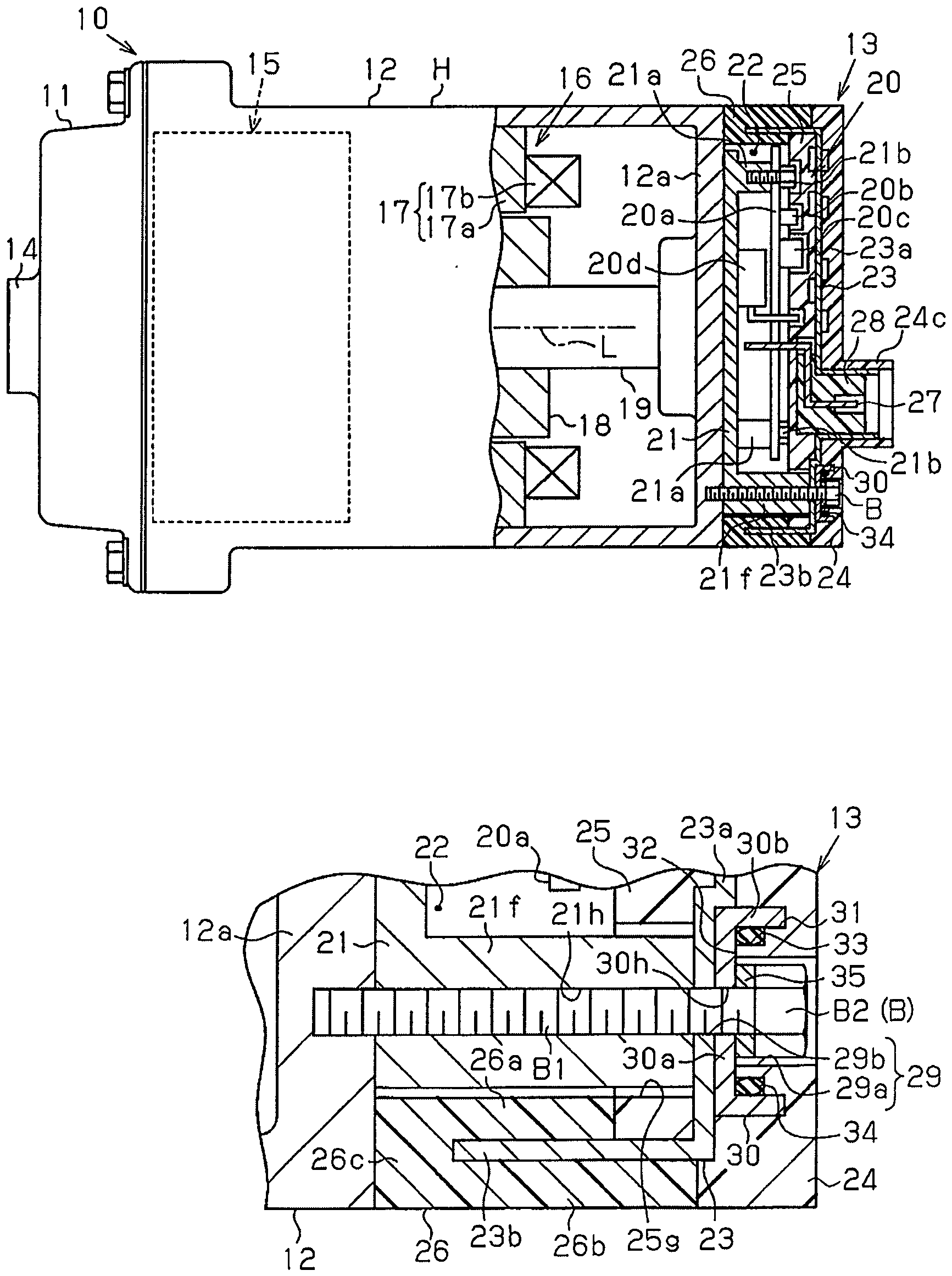
Mit Bezug auf 1A bis 4B wird nun ein motorgetriebener Verdichter einer Ausführungsform beschrieben. Der motorgetriebene Verdichter ist in einem Fahrzeug installiert und wird mit einer Fahrzeugklimaanlagenvorrichtung verwendet.Regarding 1A to 4B Now, a motor-driven compressor of an embodiment will be described. The motor-driven compressor is installed in a vehicle and used with a vehicle air conditioning apparatus.

Wie aus 1A ersichtlich ist, hat ein motorgetriebener Verdichter 10 ein Gehäuse H, das ein zylindrisches Abgabegehäuseelement 11 und ein zylindrisches Ansauggehäuseelement 12 hat, das an das Abgabegehäuseelement 11 gekoppelt ist. Das Abgabegehäuseelement 11 und das Ansauggehäuseelement 12 sind aus einem Metall hergestellt, bevorzugt aus Aluminium, und jedes hat ein offenes Ende und ein geschlossenes Ende. Das Ansauggehäuseelement 12 weist eine Umfangswand mit einem Ansauganschluss (nicht gezeigt) auf. Der Ansauganschluss ist mit einem externen Kältemittelkreislauf (nicht gezeigt) verbunden. Das Abgabegehäuseelement 11 hat einen Abgabeanschluss 14, der mit dem externen Kältemittelkreislauf verbunden ist. Das Ansauggehäuseelement 12 nimmt eine Verdichtungseinheit 15 (in 1A mit gestrichelten Linien dargestellt) auf, die ein Kältemittel verdichtet, und einen Elektromotor 16, der die Verdichtungseinheit 15 antreibt. Obwohl dies in den Zeichnungen nicht gezeigt ist, hat die Verdichtungseinheit 15 der vorliegenden Ausführungsform eine feste Schnecke, die in dem Ansauggehäuseelement 12 befestigt ist, und eine bewegliche Schnecke, die zu der festen Schnecke gerichtet ist.How out 1A it can be seen has a motor-driven compressor 10 a housing H, which is a cylindrical dispensing housing element 11 and a cylindrical suction housing member 12 has that to the dispensing housing element 11 is coupled. The discharge housing element 11 and the suction housing member 12 are made of a metal, preferably of aluminum, and each has an open end and a closed end. The intake housing element 12 has a peripheral wall with a suction port (not shown). The suction port is connected to an external refrigerant circuit (not shown). The discharge housing element 11 has a discharge connection 14 , which is connected to the external refrigerant circuit. The intake housing element 12 takes a compaction unit 15 (in 1A shown with dashed lines), which compresses a refrigerant, and an electric motor 16 who is the compaction unit 15 drives. Although not shown in the drawings, the compacting unit has 15 In the present embodiment, a fixed screw, which in the Ansauggehäuseelement 12 is fixed, and a movable screw, which is directed to the fixed screw.

Ein Stator 17 ist an der inneren Oberfläche des Ansauggehäuseelements 12 befestigt. Der Stator 17 hat einen Statorkern 17a, der an der inneren Oberfläche des Ansauggehäuseelements 12 befestigt ist, und Spulen 17b, die um Zähne (nicht gezeigt) des Statorkerns 17a gewickelt sind. Eine drehbare Drewelle 19 erstreckt sich durch den Stator 17 in dem Ansauggehäuseelement 12. Ein Rotor 18 ist an der Drehwelle 19 befestigt.A stator 17 is on the inner surface of the Ansauggehäuseelements 12 attached. The stator 17 has a stator core 17a attached to the inner surface of the suction housing element 12 is attached, and coils 17b around teeth (not shown) of the stator core 17a are wound. A rotatable three-shaft 19 extends through the stator 17 in the suction housing element 12 , A rotor 18 is at the rotary shaft 19 attached.

Das Ansauggehäuseelement 12 weist eine Endwand 12a auf, an die eine Abdeckung 13 gekoppelt ist. Die Abdeckung 13 ist zylindrisch und hat ein offenes Ende und ein geschlossenes Ende. Eine ebene Kopplungsbasis 21 ist zwischen dem Ansauggehäuseanschluss 12 und der Abdeckung 13 angeordnet. Die Kopplungsbasis 21 ist aus einem Metall hergestellt, bevorzugt aus Aluminium. Die Kopplungsbasis 21 ist mit der Endwand 12a des Ansauggehäuseelements 12 gekoppelt. Die Kopplungsbasis 21 ist thermische mit dem Ansauggehäuseelement 12 gekoppelt. Die Kopplungsbasis 21 bildet einen Abschnitt des Ansauggehäuseelements 12 (Gehäuse H).The intake housing element 12 has an end wall 12a on, to which a cover 13 is coupled. The cover 13 is cylindrical and has an open end and a closed end. A level coupling base 21 is between the intake housing connection 12 and the cover 13 arranged. The coupling base 21 is made of a metal, preferably of aluminum. The coupling base 21 is with the end wall 12a the intake housing element 12 coupled. The coupling base 21 is thermal with the intake housing element 12 coupled. The coupling base 21 forms a portion of the Ansauggehäuseelements 12 (Housing H).

Die Abdeckung 13 und die Kopplungsbasis 21 definieren eine Aufnahmekammer 22. die Aufnahmekammer 22 nimmt einen Motorantriebsschaltkreis 20 auf, der den Elektromotor 16 antreibt. Der Motorantriebsschaltkreis 20 hat eine flache Schaltkreistafel 20a und eine Mehrzahl elektrische Bauteile 20b, 20c und 20d, die elektrisch mit der Schaltkreistafel 20a verbunden sind.The cover 13 and the coupling base 21 define a receiving chamber 22 , the receiving chamber 22 takes a motor drive circuit 20 on, the electric motor 16 drives. The motor drive circuit 20 has a flat circuit board 20a and a plurality of electrical components 20b . 20c and 20d that is electrically connected to the circuit board 20a are connected.

Die Oberfläche der Kopplungsbasis 21 gegenüber der Endwand 12a des Ansauggehäuseelements 12 hat eine Mehrzahl Naben 21a, die sich in der axialen Richtung der Drehwelle 19 erstrecken. Die Schaltkreistafel 20a ist mit den Naben 21a durch das Befestigen von Kopplungsschrauben 21b an den Naben 21a gekoppelt. Der Motorantriebsschaltkreis 20 ist mit dem elektrischen Motor 16 durch Drähte (nicht gezeigt) verbunden. In der vorliegenden Ausführungsform sind die Verdichtungseinheit 15, der Elektromotor 16 und der Motorantriebsschaltkreis 20 in dieser Reihenfolge entlang der Achse L der Drehwelle 19 (in der axialen Richtung) angeordnet.The surface of the coupling base 21 opposite the end wall 12a the intake housing element 12 has a number of hubs 21a extending in the axial direction of the rotary shaft 19 extend. The circuit board 20a is with the hubs 21a by attaching coupling screws 21b at the hubs 21a coupled. The motor drive circuit 20 is with the electric motor 16 connected by wires (not shown). In the present embodiment, the compression unit 15 , of the electric motor 16 and the motor drive circuit 20 in this order along the axis L of the rotary shaft 19 arranged (in the axial direction).

In der vorliegenden Ausführungsform dienen die Schaltkreistafel 20a, die elektrischen Bauteile 20b, 20c und 20d und die Kopplungsschrauben 21d als Bauteile des Motorantriebsschaltkreises 20.In the present embodiment, the circuit board is used 20a , the electrical components 20b . 20c and 20d and the coupling screws 21d as components of the motor drive circuit 20 ,

Die Abdeckung 13 hat einen Schild 23, einen ebenen äußeren Isolator 24, der an der Außenseite (äußere Oberfläche) des Schilds 23 befestigt ist, und einen ebenen inneren Isolator 25, der an der Innenseite (innere Oberfläche) des Schilds 23 befestigt ist. Der Schild 23 ist von einer dünnen aus einem Metall hergestellten Platte ausgebildet, bevorzugt aus Aluminium, und blockiert ein elektromagnetisches Geräusch. Die äußeren und inneren Isolatoren 24 und 25 sind aus einem Harz hergestellt. Der Schild 23 und die Isolatoren 24 und 25 sind zusammengestapelt. Der Schild 23 hat einen flachen Deckel 23a, der zwischen dem äußeren Isolator 24 und dem inneren Isolator 25 gehalten ist, und einen rohrförmigen Abschnitt 23b, der sich von dem Rand des Deckels 23a in der axialen Richtung der drehenden Welle 19 erstreckt.The cover 13 has a sign 23 , a level outer insulator 24 attached to the outside (outer surface) of the shield 23 is attached, and a level internal insulator 25 which is on the inside (inner surface) of the shield 23 is attached. The shield 23 is formed of a thin plate made of a metal, preferably of aluminum, and blocks an electromagnetic noise. The outer and inner insulators 24 and 25 are made of a resin. The shield 23 and the insulators 24 and 25 are stacked together. The shield 23 has a flat lid 23a that is between the outer insulator 24 and the inner insulator 25 is held, and a tubular section 23b that extends from the edge of the lid 23a in the axial direction of the rotating shaft 19 extends.

Wie aus 1B ersichtlich ist, sind der äußere Umfangsabschnitt des äußeren Isolators 24 und der äußere Umfangsabschnitt des inneren Isolators 25 miteinander durch ein ringförmiges Harzanschlussstück 26 gefügt. Das Anschlussstück 26 hat einen inneren Anschlussstückabschnitt 26a, der an der Innenseite des rohrförmigen Abschnitts 23b des Schilds 23 angeordnet ist. Der innere Anschlussstückabschnitt 26a ist mit dem äußeren Umfangsabschnitt des inneren Isolators 25 kontinuierlich. Das Anschlussstück 26 hat ebenfalls einen äußeren Anschlussstückabschnitt 26b, der an der Außenseite des rohrförmigen Abschnitts 23b des Schilds 23 angeordnet ist. Der äußere Anschlussstückabschnitt 26b ist mit dem äußeren Umfangsabschnitt des äußeren Isolators 24 kontinuierlich. Außerdem hat das Anschlussstück 26 einen Verbindungsabschnitt 26c, der an dem distalen Ende des rohrförmigen Abschnitts 23b des Schilds 23 angeordnet ist. Der Verbindungsabschnitt 26c verbindet den inneren Anschlussstückabschnitt 26a mit dem äußeren Anschlussstückabschnitt 26b.How out 1B is apparent, are the outer peripheral portion of the outer insulator 24 and the outer peripheral portion of the inner insulator 25 through each other through an annular resin fitting 26 together. The connection piece 26 has an inner connector section 26a which is on the inside of the tubular section 23b of the shield 23 is arranged. The inner connector section 26a is with the outer peripheral portion of the inner insulator 25 continuously. The connection piece 26 also has an outer fitting section 26b placed on the outside of the tubular section 23b of the shield 23 is arranged. The outer fitting section 26b is with the outer peripheral portion of the outer insulator 24 continuously. In addition, the connector has 26 a connection section 26c at the distal end of the tubular section 23b of the shield 23 is arranged. The connecting section 26c connects the inner connector section 26a with the outer fitting portion 26b ,

Wie aus 2 ersichtlich ist, ist die innere Oberfläche des äußeren Isolators 24 zu dem Motorantriebsschaltkreis 20 gerichtet (zu dem Schild 23 gerichtet), und hat Aussparungen 24a, wo der äußere Isolator 24 der Schild 23 nicht berührt, und Vorsprünge 24t, wo der äußere Isolator 24 der Schild 23 berührt. Die äußere Oberfläche des inneren Isolators 25 ist von dem Motorantriebsschaltkreis 20 weg gerichtet (zu dem Schild 23 gerichtet), und hat Aussparungen 25a, wo der innere Isolator 25 den Schild 23 nicht berührt, und Vorsprünge 25t, wo der innere Isolators 25 den Schild 23 berührt. Außerdem ist die innere Oberfläche des inneren Isolators 25 zu dem Motorantriebsschaltkreis 20 gerichtet und hat Aussparungen 25b bis 25e. Aufgrund der Aussparungen 25b und 25c ist ein Zusammenstoßen zwischen dem inneren Isolator 25 und den elektrischen Bauteilen 20b und 20c vermieden. Aufgrund der Aussparung 25d ist ein Zusammenstoßen zwischen dem inneren Isolator 25 und dem distalen Ende einer Führung 201d vermieden, die sich von dem elektrischen Bauteil 20d zu dem inneren Isolator 25 erstreckt. Aufgrund der Aussparung 25e ist ein Zusammenstoßen zwischen dem inneren Isolator 25 und einer Kopplungsschraube 21b vermieden. Zusätzlich hat die innere Oberfläche des inneren Isolators 25 Vorsprünge 25k, die sich zwischen den elektrischen Bauteilen 20b und 20c erstrecken, die Führung 201d des elektrischen Bauteils 20d und die Kopplungsschraube 21b.How out 2 is apparent, is the inner surface of the outer insulator 24 to the motor drive circuit 20 directed (to the sign 23 directed), and has recesses 24a where the outer insulator 24 the shield 23 not touched, and protrusions 24t where the outer insulator 24 the shield 23 touched. The outer surface of the inner insulator 25 is from the motor drive circuit 20 directed away (to the sign 23 directed), and has recesses 25a where the inner insulator 25 the shield 23 not touched, and protrusions 25t where the inner insulator 25 the shield 23 touched. In addition, the inner surface of the inner insulator 25 to the motor drive circuit 20 directed and has recesses 25b to 25e , Because of the recesses 25b and 25c is a collision between the inner insulator 25 and the electrical components 20b and 20c avoided. Because of the recess 25d is a collision between the inner insulator 25 and the distal end of a guide 201d avoided, which differs from the electrical component 20d to the inner insulator 25 extends. Because of the recess 25e is a collision between the inner insulator 25 and a coupling screw 21b avoided. In addition, the inner surface of the inner insulator has 25 projections 25k that is between the electrical components 20b and 20c extend the lead 201d of the electrical component 20d and the coupling screw 21b ,

Die äußere Oberfläche des Deckels 23a des Schilds 23 hat einen rohrförmigen inneren Verbindungsabschnitt 23c, der sich in der axialen Richtung der drehenden Welle 19 erstreckt. Die äußere Oberfläche des äußeren Isolators 24, der von dem Motorantriebsschaltkreis 20 weg gerichtet ist (und dem Schild 23), hat einen rohrförmigen äußeren Verbindungsabschnitt 24c, der sich in der axialen Richtung der Drehwelle 19 erstreckt. Der innere Verbindungsabschnitt 23c ist an der inneren Seite des äußeren Verbindungsabschnitts 24c angeordnet.The outer surface of the lid 23a of the shield 23 has a tubular inner connecting portion 23c moving in the axial direction of the rotating shaft 19 extends. The outer surface of the outer insulator 24 that of the motor drive circuit 20 is directed away (and the shield 23 ), has a tubular outer connecting portion 24c extending in the axial direction of the rotary shaft 19 extends. The inner connection section 23c is on the inner side of the outer joint portion 24c arranged.

Ein Verbinder 28 ist zwischen dem Schild 23 und dem inneren Isolator 25 befestigt. Der Verbinder 28 hat einen Metallanschluss 27, der elektrisch mit einer externen Leistungszufuhr (Fahrzeugbatterie) verbunden ist. der Metallanschluss 27 hat einen ersten Endabschnitt und einen zweiten Endabschnitt, der dem ersten Endabschnitt gegenüberliegt. Der Verbinder 28 hat ebenfalls einen Halteabschnitt 28a und einen Flansch 28b. Der Halteabschnitt 28a ist in dem inneren Verbindungsabschnitt 23c des Schilds 23 angeordnet und hält den ersten Endabschnitt des Metallanschlusses 27. Der Flansch 28b erstreckt sich von dem proximalen Ende des Halteabschnitts 28a zu dem zweiten Endabschnitt des Metallanschlusses 27. Der erste Endabschnitt des Metallanschlusses 27 erstreckt sich durch eine Aussparung in dem distalen Ende des Halteabschnitts 28a und ist nach außen freigelegt, um mit einer externen Leistungszufuhr verbunden zu werden.A connector 28 is between the shield 23 and the inner insulator 25 attached. The connector 28 has a metal connection 27 which is electrically connected to an external power supply (vehicle battery). the metal connection 27 has a first end portion and a second end portion opposite to the first end portion. The connector 28 also has a holding section 28a and a flange 28b , The holding section 28a is in the inner connecting portion 23c of the shield 23 arranged and holds the first end portion of the metal terminal 27 , The flange 28b extends from the proximal end of the holding portion 28a to the second end portion of the metal terminal 27 , The first end portion of the metal terminal 27 extends through a recess in the distal end of the holding portion 28a and is exposed to the outside to be connected to an external power supply.

Die äußere Oberfläche des inneren Isolators 25 hat eine Aufnahmeaussparung 25f, die das proximale Ende des Halteabschnitts 28a und des Flanschs 28b aufnimmt. Der Flansch 28b ist zwischen dem Boden der Aufnahmeaussparung 25f und dem Deckel 23a des Schilds 23 gehalten und positioniert. Der Abschnitt des inneren Isolators 25, der den Boden der Aufnahmeaussparung 25f definiert, hat eine Einfügebohrung 25h, die den zweiten Endabschnitt des Metallanschlusses 27 empfängt. Der zweite Endabschnitt des Metallanschlusses 27 erstreckt sich durch die Einfügebohrung 25h und ist elektrisch mit der Schaltkreistafel 20a verbunden.The outer surface of the inner insulator 25 has a recording recess 25f connecting the proximal end of the holding section 28a and the flange 28b receives. The flange 28b is between the bottom of the receiving recess 25f and the lid 23a of the shield 23 held and positioned. The section of the inner insulator 25 holding the bottom of the receiving recess 25f defined, has one fitting bore 25h that the second end portion of the metal terminal 27 receives. The second end portion of the metal terminal 27 extends through the insertion hole 25h and is electrically connected to the circuit board 20a connected.

Wie aus 1B ersichtlich ist, hat die Oberfläche der Kopplungsbasis 21 gegenüber der Endwand 12a des Ansauggehäuseelements 12 eine Mehrzahl Naben 21f (nur eine ist in 1B gezeigt), die sich der axialen Richtung der Drehwelle 19 erstreckt. Jede Nabe 21f hat ein flaches distales Ende, das mit der inneren Oberfläche des Deckels 23a des Schilds 23 in Berührung ist. Die Nabe 21f erstreckt sich durch eine Durchgangsbohrung 25g, die in dem inneren Isolator 25 ausgebildet ist. Zusätzlich hat jede Nabe 21f eine Durchgangsbohrung 21h.How out 1B can be seen, has the surface of the coupling base 21 opposite the end wall 12a the intake housing element 12 a plurality of hubs 21f (only one is in 1B shown), which is the axial direction of the rotary shaft 19 extends. Every hub 21f has a flat distal end that matches the inner surface of the lid 23a of the shield 23 is in contact. The hub 21f extends through a through hole 25g in the inner insulator 25 is trained. In addition, every hub has 21f a through hole 21h ,

Die Abdeckung 13 hat Einfügebohrungen 29, in die Schrauben B eingefügt werden können. Jede Einfügebohrung 29 hat eine erste Einfügebohrung 29a, die in dem äußeren Isolator 24 ausgebildet ist, und eine zweite Einfügebohrung 29b, die in dem Schild 23 ausgebildet ist. Die erste Einfügebohrung 29a hat einen größeren Durchmesser als die zweite Einfügebohrung 29b. Die erste Einfügebohrung 29a ist mit der zweiten Einfügebohrung 29b ausgerichtet. Jede Schraube B hat eine Gewindestange B1 und einen Kopf B2, die an dem proximalen Ende der Gewindestange B1 angeordnet ist.The cover 13 has insertion holes 29 , in which screws B can be inserted. Each insertion hole 29 has a first insertion hole 29a in the outer insulator 24 is formed, and a second insertion hole 29b in the sign 23 is trained. The first insertion hole 29a has a larger diameter than the second insertion hole 29b , The first insertion hole 29a is with the second insertion hole 29b aligned. Each screw B has a threaded rod B1 and a head B2 attached to the proximal end of the threaded rod B1 is arranged.

Ein Abstandhalter 30 ist zwischen dem Kopf B2 von jeder Schraube B und dem Schild 23 angeordnet. Der Abstandhalter 30 ist aus einem Metall hergestellt, bevorzugt aus Aluminium, und bildet einen Abschnitt des Schilds 23. Der Abstandhalter 30 hat einen flachen Endabschnitt 30a und eine rohrförmigen Abschnitt 30b, der sich von dem Rand des Endabschnitts 30a rechtwinklig zu dem Endabschnitt 30a erstreckt. Der Endabschnitt 30a hat eine Einfügebohrung 30h, in die die Stange B1 der Schraube B eingefügt werden kann. Die Stange B1 ist durch die erste Einfügebohrung 29a, die Einfügebohrung 30h, die zweite Einfügebohrung 29b und die Durchgangsbohrung 21h eingefügt. Dann wird die Stange B1 an der Endwand 12a des Ansauggehäuseelements 12 befestigt. Dies koppelt die Abdeckung 13 an die Endwand 12a des Ansauggehäuseelements 12. Die Kopplungsbasis 21 ist zwischen der Abdeckung 13 und der Endwand 12a angeordnet.A spacer 30 is between the head B2 from each screw B and the shield 23 arranged. The spacer 30 is made of a metal, preferably of aluminum, and forms a portion of the shield 23 , The spacer 30 has a flat end section 30a and a tubular section 30b that extends from the edge of the end section 30a perpendicular to the end portion 30a extends. The end section 30a has an insertion hole 30h into the bar B1 the screw B can be inserted. The pole B1 is through the first insertion hole 29a , the insertion hole 30h , the second insertion hole 29b and the through hole 21h inserted. Then the pole B1 on the end wall 12a the intake housing element 12 attached. This couples the cover 13 to the end wall 12a the intake housing element 12 , The coupling base 21 is between the cover 13 and the end wall 12a arranged.

Die innere Oberfläche des äußeren Isolators 24 hat ringförmige Nuten 31. Aufnahmeaussparungen 32 sind zwischen der inneren Oberfläche des äußeren Isolators 24 und dem Schild 23 ausgebildet. Jede ringförmige Nut 31 empfängt den rohrförmigen Abschnitt 30b des entsprechenden Abstandhalters 30, und jede Aufnahmeaussparung 32 nimmt den Endabschnitt 30a des entsprechenden Abstandhalters 30 auf.The inner surface of the outer insulator 24 has annular grooves 31 , receiving recesses 32 are between the inner surface of the outer insulator 24 and the shield 23 educated. Each annular groove 31 receives the tubular section 30b the corresponding spacer 30 , and every recording recess 32 takes the end section 30a the corresponding spacer 30 on.

Der äußere Isolator 24 hat ebenfalls eine Dichtungsaufnahmenut 33, die an der Innenseite jeder ringförmigen Nut 31 angeordnet ist. Die Dichtungsaufnahmenuten 33 sind ringförmig und mit den entsprechenden der ringförmigen Nuten 31 und der Aufnahmeaussparungen 32 kontinuierlich. Jede Dichtungsaufnahmenut 33 nimmt ein ringförmiges Dichtelement 34 auf, das die erste Einfügebohrung 29a umgibt. Das Dichtelement 34 ist zwischen der inneren Oberfläche des rohrförmigen Abschnitts 30b des Abstandhalters 30 und der Wand der Dichtungsaufnahmenut 33 gehalten, die zu der inneren Oberfläche des rohrförmigen Abschnitts 30b gerichtet ist. Somit wird das Dichtelement 34 in einer Richtung rechtwinklig zu der Achse der Stange B1 der Schraube B verdichtet. Das Dichtelement 34 dichtet den Spalt zwischen dem Schild 23 und dem äußeren Isolator 24 ab.The outer insulator 24 also has a seal receiving groove 33 placed on the inside of each annular groove 31 is arranged. The seal intake grooves 33 are annular and with the corresponding annular grooves 31 and the recording cutbacks 32 continuously. Each gasket intake groove 33 takes an annular sealing element 34 on, this is the first insertion hole 29a surrounds. The sealing element 34 is between the inner surface of the tubular portion 30b of the spacer 30 and the wall of the gasket intake groove 33 held to the inner surface of the tubular portion 30b is directed. Thus, the sealing element 34 in a direction perpendicular to the axis of the rod B1 the screw B compacted. The sealing element 34 seals the gap between the shield 23 and the outer insulator 24 from.

Der Kopf B2 jeder Schraube B ist in der entsprechenden ersten Einfügebohrung 29a angeordnet. Eine Scheibe 35 ist zwischen dem Endabschnitt 30a von jedem Abstandhalter 30 und dem Kopf B2 der entsprechenden Schraube B in der axialen Richtung der Stange B1 der Schraube B angeordnet. Die Scheibe 35, die aus einem Metall hergestellt ist, bevorzugt aus Aluminium, umgibt die Stange B1. Die Scheibe 35 dichtet den Spalt zwischen dem Endabschnitt 30a des Abstandhalters 30 und dem Kopf B2 der Schraube B ab. Der Abschnitt des Schilds 23, der die zweite Einfügebohrung 29b umgibt, ist zwischen dem Kopf B2 der Schraube B und der Nabe 21f gehalten. Die axiale Kraft der Schraube B ist auf diesen Abschnitt durch den Abstandhalter 30 und die Scheibe 35 aufgebracht, ohne auf den inneren Isolator 24 oder den äußeren Isolator 25 aufgebracht zu werden.The head B2 each screw B is in the corresponding first insertion hole 29a arranged. A disk 35 is between the end section 30a from each spacer 30 and the head B2 the corresponding screw B in the axial direction of the rod B1 the screw B arranged. The disc 35 made of a metal, preferably of aluminum, surrounds the rod B1 , The disc 35 seals the gap between the end portion 30a of the spacer 30 and the head B2 from the B screw. The section of the shield 23 , the second insertion hole 29 b surrounds, is between the head B2 the screw B and the hub 21f held. The axial force of screw B is on this section through the spacer 30 and the disc 35 Applied without affecting the inner insulator 24 or the outer insulator 25 to get upset.

Das Verfahren zum Herstellen der Abdeckung wird nun beschrieben.The method of manufacturing the cover will now be described.

Mit Bezug auf 3 werden im Voraus der äußere Isolator 24 und der innere Isolator 25 getrennt geformt. Dann wird der Verbinder 28 an dem inneren Isolator 25 derart angebracht, dass die Einfügebohrung 25h den zweiten Endabschnitt des Metallanschlusses 27 empfängt, und die Aufnahmeaussparung 25f das proximale Ende des Halteabschnitts 28a und den Flansch 28b des Verbinders 28 aufnimmt. Dann ist der Schild 23 an der äußeren Oberfläche des inneren Isolators 25 angebracht. Dies positioniert den Halteabschnitt 28a in dem inneren Verbindungsabschnitt 23c.Regarding 3 Become the outer insulator in advance 24 and the inner insulator 25 shaped separately. Then the connector 28 on the inner insulator 25 mounted so that the insertion hole 25h the second end portion of the metal terminal 27 receives, and the recording recess 25f the proximal end of the holding section 28a and the flange 28b of the connector 28 receives. Then the sign 23 on the outer surface of the inner insulator 25 appropriate. This positions the holding section 28a in the inner connecting portion 23c ,

Dann ist der Abstandhalter 30, der das Dichtelement 34 aufnimmt, in der ringförmigen Nut 31 und der Aufnahmeaussparung 32 des äußeren Isolators 24 angeordnet. Der äußere Isolator 24 ist dann an der äußeren Oberfläche des Deckels 23a des Schilds 23 angebracht. Dies positioniert den inneren Verbindungsabschnitt 23c in dem äußeren Verbindungsabschnitt 24c. Zusätzlich ist der Schild 23 zwischen dem äußeren Isolator 24 und dem inneren Isolator 25 gehalten.Then the spacer 30 that is the sealing element 34 receives, in the annular groove 31 and the recording recess 32 of the outer insulator 24 arranged. The outer insulator 24 is then on the outer surface of the lid 23a of the shield 23 appropriate. This positions the inner connection section 23c in the outer one connecting portion 24c , In addition, the shield 23 between the outer insulator 24 and the inner insulator 25 held.

Wie aus 4A ersichtlich ist, sind der Schild 23, der äußere Isolator 24 und der innere Isolator 25 in einer Form 40 angeordnet, die ein erstes Formelement 40a und ein zweites Formelement 40b hat. Dies bildet eine Füllhöhlung 41 in der Form 40 aus. Die Füllhöhlung 41 erstreckt sich von dem äußeren Umfangsabschnitt des äußeren Isolators 24, geht neben dem distalen Ende des rohrförmigen Abschnitts 23b des Schilds 23 vorbei, und erstreckt sich zu dem äußeren Umfangsabschnitt des inneren Isolators 25.How out 4A is apparent, are the shield 23 , the outer insulator 24 and the inner insulator 25 in a form 40 arranged, which is a first form element 40a and a second mold element 40b Has. This forms a Füllhöhlung 41 in the shape 40 out. The filling cavity 41 extends from the outer peripheral portion of the outer insulator 24 , passes next to the distal end of the tubular section 23b of the shield 23 over, and extends to the outer peripheral portion of the inner insulator 25 ,

Wie als 4B ersichtlich ist, ist die Füllhöhlung 41 mit geschmolzenem Harz gefüllt, das dann ausgehärtet wird. Dies bildet das Anschlussstück 26 in der Füllhöhlung 41. Das Anschlussstück 26 fügt den äußeren Umfangsabschnitt des äußeren Isolators 24 mit dem äußeren Umfangsabschnitt des inneren Isolators 25. Dies bildet die dreischichtige Abdeckung 13, in welcher der äußere Isolator 24 an der äußeren Oberfläche des Schilds 23 befestigt ist, und der innere Isolator 25 an der inneren Oberfläche des Schilds 23 befestigt ist. Wenn die Abdeckung 13 von der Form 40 entfernt und auf Raumtemperatur zurückgeführt wird, unterliegt das Anschlussstück 26 einer thermischen Kontraktion. Dies bildet die Abdeckung 13, die die gewünschte Form und eine hohe Abmessungsgenauigkeit aufweist.Such as 4B can be seen, is the Füllhöhlung 41 filled with molten resin, which is then cured. This forms the connection piece 26 in the filling cavity 41 , The connection piece 26 inserts the outer peripheral portion of the outer insulator 24 with the outer peripheral portion of the inner insulator 25 , This forms the three-layer cover 13 in which the outer insulator 24 on the outer surface of the shield 23 is attached, and the inner insulator 25 on the inner surface of the shield 23 is attached. If the cover 13 from the mold 40 removed and returned to room temperature, subject to the fitting 26 a thermal contraction. This forms the cover 13 which has the desired shape and a high dimensional accuracy.

Der Betrieb der vorliegenden Ausführungsform wird nun beschrieben.The operation of the present embodiment will now be described.

Die Abdeckung 13 wird durch das lediglich Fügen des äußeren Umfangsabschitts des äußeren Isolators 24 mit dem äußeren Umfangsabschnitt des inneren Isolators 25 mit dem Anschlussstück 26 ausgebildet, wenn der Schild 23 zwischen dem äußeren Isolator 24 und dem inneren Isolator 25 gehalten ist. Dies begrenzt allgemein die thermische Kontraktion des Schilds 23, des äußeren Isolators 24 und des inneren Isolators 25, die verursacht werden würde, falls ein Formen durchgeführt werden würde, um die dreischichtige Abdeckung 13 auszubilden. Falls die dreischichtige Abdeckung 13 durch das Durchführen eines Formens ausgebildet werden würde, könnten sich der Schild 23, der äußere Isolator 24 und der innere Isolator 25 verformen, falls diese Abschnitte sich nicht gleichmäßig zusammenziehen. Diesbezüglich begrenzt die vorliegende Ausführungsform eine derartige Verformung. Dies gestattet es, dass die Abdeckung 13 die gewünschte Form und eine hohe Abmessungsgenauigkeit aufweist.The cover 13 is achieved by merely joining the outer peripheral portion of the outer insulator 24 with the outer peripheral portion of the inner insulator 25 with the connector 26 trained when the shield 23 between the outer insulator 24 and the inner insulator 25 is held. This generally limits the thermal contraction of the shield 23 , the outer insulator 24 and the inner insulator 25 that would be caused if molding were performed to the three-layer cover 13 train. If the three-layer cover 13 would be formed by performing a molding, could the shield 23 , the outer insulator 24 and the inner insulator 25 deform if these sections do not contract evenly. In this regard, the present embodiment limits such deformation. This allows the cover 13 has the desired shape and a high dimensional accuracy.

Der motorgetriebene Verdichter 10 ist in einem Fahrzeug eingebaut. Somit können die Wärme von der Fahrzeugmaschine und die Wärme der Umgebungsluft die Abdeckung 13 verformen. Jedoch begrenzen die Aussparungen 24a, 25a, 25b, 25c, 25d und 25e und die Vorsprünge 24t, 25k und 25t die durch die Wärme verursachte Verformung der Abdeckung 13. Dies verbessert die Lebensdauer der Abdeckung 13. Das Dichtelement 34 ist zwischen dem äußeren Isolator 24 und dem Abstandhalter 30 angeordnet. Das Dichtelement 34 dichtet den Spalt zwischen dem äußeren Isolator 24 und dem Abstandhalter 30 ab, das Dichtelement 34 dichtet nämlich den Spalt zwischen dem Schild 23 und dem äußeren Isolator 24 ab. Somit stellt das Dichtelement 34 die Abdichtung zwischen dem Schild 23 und dem äußeren Isolator 24 sicher. Dies blockiert das Eindringen von Fremdstoffen wie z. B. Wasser und Staub in die Aufnahmekammer 22 durch den Spalt zwischen dem Schild 23 und dem äußeren Isolator 24.The motor-driven compressor 10 is installed in a vehicle. Thus, the heat from the vehicle engine and the heat of the ambient air can cover 13 deform. However, the recesses limit 24a . 25a . 25b . 25c . 25d and 25e and the projections 24t . 25k and 25t the deformation of the cover caused by the heat 13 , This improves the life of the cover 13 , The sealing element 34 is between the outer insulator 24 and the spacer 30 arranged. The sealing element 34 seals the gap between the outer insulator 24 and the spacer 30 from, the sealing element 34 namely seals the gap between the shield 23 and the outer insulator 24 from. Thus, the sealing element 34 the seal between the shield 23 and the outer insulator 24 for sure. This blocks the penetration of foreign substances such. As water and dust in the receiving chamber 22 through the gap between the shield 23 and the outer insulator 24 ,

Außerdem umgibt das Dichtelement 34 die erste Einfügebohrung 29a. Dies blockiert das Eindringen von Fremdstoffen von der ersten Einfügebohrung 29a in die Aufnahmekammer 22 durch den Spalt zwischen dem Schild 23 und dem äußeren Isolator 24, wenn die Abdeckung 13 mit der Schraube B an das Ansauggehäuseelement 12 gekoppelt wird.In addition, the sealing element surrounds 34 the first insertion hole 29a , This blocks the entry of foreign matter from the first insertion hole 29a in the receiving chamber 22 through the gap between the shield 23 and the outer insulator 24 if the cover 13 with the screw B to the intake housing 12 is coupled.

Der Abschnitt des Schilds 23, der die zweite Einfügebohrung 29b umgibt, ist zwischen dem Kopf B2 der Schraube B und der Nabe 21f gehalten. Die Axialkraft der Schraube B wird durch den Abstandhalter 30 auf diesen Abschnitt aufgebracht, und nicht auf den äußeren Isolator 24 oder den inneren Isolator 25 aufgebracht. Wenn die Abdeckung 13 mit der Schraube B an das Ansauggehäuseelement 12 gekoppelt ist, sind der äußere Isolator 24 und der innere Isolator 25 nicht zwischen dem Kopf B2 und der Nabe 21f gehalten. Somit verformt die Axialkraft der Schraube B den äußeren Isolator 24 oder den inneren Isolator 25 nicht. Dies vermeidet eine Verschlechterung der Dichtung des Ansauggehäuseelements 12 mit der Abdeckung 13, die verursacht werden würde, wenn der äußere Isolator 24 oder der innere Isolator 25 sich verformt und die Schraube B lockert.The section of the shield 23 , the second insertion hole 29b surrounds, is between the head B2 the screw B and the hub 21f held. The axial force of screw B is through the spacer 30 applied to this section, and not to the outer insulator 24 or the inner insulator 25 applied. If the cover 13 with the screw B to the intake housing 12 coupled are the outer insulator 24 and the inner insulator 25 not between the head B2 and the hub 21f held. Thus, the axial force of the screw B deforms the outer insulator 24 or the inner insulator 25 Not. This avoids deterioration of the seal of the suction housing member 12 with the cover 13 that would be caused if the outer insulator 24 or the inner insulator 25 deforms and loosens the screw B.

Die Vorteile der vorliegenden Ausführungsform werden nun beschrieben.

  1. (1) Die Abdeckung 13, die den Schild 23, den äußeren Isolator 24 und den inneren Isolator 25 hat, die voneinander getrennt sind, ist durch Fügen des äußeren Umfangsabschnitts des äußeren Isolators 24 an den äußeren Umfangsabschnitt des inneren Isolators 25 mit dem Anschlussstück 26 ausgebildet, wenn der Schild 23 zwischen dem äußeren Isolator 24 und dem inneren Isolator 25 gehalten ist. Somit kann die dreischichtige Abdeckung 13, in der der Schild 23, der äußere Isolator 24 und der innere Isolator 25 integriert sind, lediglich durch Fügen des äußeren Umfangsabschnitts des äußeren Isolators 24 an den äußeren Umfangsabschnitt des inneren Isolators 25 ausgebildet werden, wenn der Schild 23 zwischen dem äußeren Isolator 24 und dem inneren Isolator 25 gehalten ist. Dies begrenzt die allgemeine thermische Kontraktion des Schilds 23, des äußeren Isolators 24 und des inneren Isolators 25, die verursacht werden würde, falls die dreischichtige Abdeckung 13 durch Formen ausgebildet werden würde. In der dreischichtigen Abdeckung 13, die durch Formen ausgebildet ist, können der Schild 23, der äußere Isolator 24 und der innere Isolator 25 sich verformen, falls diese Abschnitte sich nicht gleichmäßig zusammenziehen. Die vorliegende Ausführungsform begrenzt eine derartige Verformung. Dies gestattet es, dass die Abdeckung 13 die gewünschte Form und eine hohe Abmessungsgenauigkeit aufweist.
  2. (2) Der äußere Isolator 24 und der innere Isolator 25 haben die Aussparungen 24a und 25a, wo eine Berührung mit dem Schild 23 nicht auftritt, und die Vorsprünge 24t und 25t, wo eine Berührung mit dem Schild 23 auftritt. Im Vergleich mit einer Struktur, in der die gesamte Oberfläche des äußeren Isolators 24, der zu dem Schild 23 gerichtet ist, und die gesamte Oberfläche des inneren Isolators 25, der zu dem Schild 23 gerichtet ist, in naher Berührung mit dem Schild 23 sind, begrenzen die Aussparungen 24a und 25a und die Vorsprünge 24t und 25t die Verformung der Abdeckung 13, die durch Wärme verursacht werden kann. Dies verbessert die Lebensdauer der Abdeckung 13.
  3. (3) Der innere Isolator 25 hat die Aussparungen 25b, 25c, 25d und 25e, so dass der innere Isolator 25 nicht mit den elektrischen Bauteilen 20b und 20c zusammenstößt, die Führung 201d des elektrischen Bauteils 20d und die Kopplungsschraube 21b. Der innere Isolator 25 hat ebenfalls die Vorsprünge 25k, die sich zwischen den elektrischen Bauteilen 20b und 20c erstrecken, die Führung 201d der elektrischen Bauteile 20d und die Kopplungsschraube 21b. Die Aussparungen 25b, 25c, 25d und 25e gestatten es, dass der Abstand zwischen dem inneren Isolator 25 und dem Motorantriebsschaltkreis 20 minimiert ist. Dies reduziert die Größe des motorgetriebenen Verdichters 10. Zusätzlich verstärken die Vorsprünge 25k den inneren Isolator 25.
  4. (4) Das Anschlussstück 26 fügt den äußeren Umfangsabschnitt des äußeren Isolators 24 und den äußeren Umfangsabschnitt des inneren Isolators 25. Dies gestattet eine einfache Verbindung des äußeren Umfangsabschnitts des äußeren Isolators 24 und des äußeren Umfangsabschnitts des inneren Isolators 25.
  5. (5) Der Verbinder 28, der elektrisch mit der externen Leistungszufuhr verbunden ist, ist zwischen dem Schild 23 und dem inneren Isolator 25 befestigt. Dies gestattet, dass der Verbinder 28 lediglich durch Halten des Verbinders 28 zwischen dem Schild 23 und dem inneren Isolator 25 befestigt ist.
  6. (6) Das Dichtelement 34, dass das Eindringen von Fremdstoffen in die Aufnahmekammer 22 verhindert, ist zwischen dem Schild 23 und dem äußeren Isolator 24 angeordnet. Das Dichtelement 34 dichtet den Spalt zwischen dem Schild 23 und dem äußeren Isolator 24 ab. Somit stellt das Dichtelement 34 die Dichtung zwischen dem Schild 23 und dem äußeren Isolator 24 sicher. Dies blockiert das Eindringen von Fremdstoffen in die Aufnahmekammer 22 durch den Spalt zwischen dem Schild 23 und dem äußeren Isolator 24.
  7. (7) Das Dichtelement 34 ist in einer Richtung rechtwinklig zu der Achse der Schraube B verdichtet. Falls das Dichtelement 34 in der axialen Richtung der Schraube B verdichtet werden würde, würde z. B. das Dichtelement 34 eine elastische Kraft erzeugen, die wirkt, um die ursprüngliche Form des Dichtelements 34 wiederherzustellen. Dies würde zwischen dem Schild 23 und dem äußeren Isolator 24 einen Spalt erzeugen. Die vorliegende Ausführungsform vermeidet ein derartiges Problem.
  8. (8) Das Dichtelement 34 umgibt die erste Einfügebohrung 29a. Dies blockiert das Eindringen von Fremdstoffen von der ersten Einfügebohrung 29a in die Aufnahmekammer 22 durch den Spalt zwischen dem Schild 23 und dem äußeren Isolator 24, wenn die Abdeckung 13 an das Ansauggehäuseelement 12 mit der Schraube B gekoppelt wird.
  9. (9) Der Abschnitt des Schilds 23, der die zweite Einfügebohrung 29b umgibt, ist zwischen dem Kopf B2 der Schraube B und der Nabe 21f gehalten. Die Axialkraft der Schraube B ist auf diesen Abschnitt durch den Abstandhalter 30 aufgebracht und nicht auf den äußeren Isolator 24 oder den inneren Isolator 25 aufgebracht. Wenn die Abdeckung 13 mit der Schraube B an das Ansauggehäuseelement 12 gekoppelt ist, sind der äußere Isolator 24 und der innere Isolator 25 nicht zwischen dem Kopf B2 und der Nabe 21f gehalten. Somit verformt die Axialkraft der Schraube B den äußeren Isolator 24 oder den inneren Isolator 25 nicht. Dies vermeidet eine Verschlechterung der Dichtung zwischen dem Ansauggehäuseelement 12 und der Abdeckung 13, die verursacht werden würde, wenn der äußere Isolator 24 oder der innere Isolator 25 sich verformt und die Schraube B lockert.
  10. (10) Falls der äußere Isolator 24 und der innere Isolator 25 durch Füllen einer Form mit geschmolzenem Harz an den äußeren und inneren Seiten des Schilds 23 und dann Härten des geschmolzenen Harzes ausgebildet werden würde, müsste ein Stift in der Form angeordnet sein, um den Schild 23 in der Form zu halten und zu befestigen. Dies würde jedoch eine unnötige Bohrung in dem geformten äußeren Isolator 24 oder dem inneren Isolator 25 an der Position ausbilden, an der der Stift während des Formens angeordnet war. In der vorliegenden Ausführungsform sind der äußere Isolator 24 und der innere Isolator 25 getrennt im Voraus geformt und weisen keine unnötige Bohrung auf. Dies verbessert die Qualität der Abdeckung 13.
  11. (11) Falls zusätzlich der äußere Isolator 24 und der innere Isolator 25 durch Füllen einer Form mit geschmolzenem Harz an den äußeren und inneren Seiten des Schilds 23 ausgebildet werden würden, wie voranstehend beschrieben wurde, würden Begrenzungen auf die Formen des äußeren Isolators 24 und des inneren Isolators 25 aufgrund der Begrenzung der Richtung ausgeübt werden, in der die geformte Abdeckung von der Form entfernt wird. Jedoch sind in der vorliegenden Ausführungsform der äußere Isolator 24 und der innere Isolator 25 im Voraus geformt und weisen die gewünschte Form und eine hohe Abmessungsgenauigkeit auf. Somit können unnötige Abschnitte von dem äußeren Isolator 24 und dem inneren Isolator 25 weggelassen werden. Dies reduziert das Gewicht der Abdeckung 13.
The advantages of the present embodiment will now be described.
  1. (1) The cover 13 that the shield 23 , the outer insulator 24 and the inner insulator 25 has, which are separated from each other, is by joining the outer peripheral portion of the outer insulator 24 to the outer peripheral portion of the inner insulator 25 with the connector 26 educated, if the shield 23 between the outer insulator 24 and the inner insulator 25 is held. Thus, the three-layer cover 13 in which the sign 23 , the outer insulator 24 and the inner insulator 25 are integrated, merely by joining the outer peripheral portion of the outer insulator 24 to the outer peripheral portion of the inner insulator 25 be trained when the shield 23 between the outer insulator 24 and the inner insulator 25 is held. This limits the general thermal contraction of the shield 23 , the outer insulator 24 and the inner insulator 25 that would be caused if the three-layered cover 13 would be formed by molding. In the three-layer cover 13 that is formed by forms, the shield can 23 , the outer insulator 24 and the inner insulator 25 deform if these sections do not contract evenly. The present embodiment limits such deformation. This allows the cover 13 has the desired shape and a high dimensional accuracy.
  2. (2) The outer insulator 24 and the inner insulator 25 have the recesses 24a and 25a where a touch with the shield 23 does not occur, and the projections 24t and 25t where a touch with the shield 23 occurs. In comparison with a structure in which the entire surface of the outer insulator 24 that to the shield 23 is directed, and the entire surface of the inner insulator 25 that to the shield 23 is directed, in close contact with the shield 23 are, limit the recesses 24a and 25a and the projections 24t and 25t the deformation of the cover 13 that can be caused by heat. This improves the life of the cover 13 ,
  3. (3) The inner insulator 25 has the cutouts 25b . 25c . 25d and 25e so that the inner insulator 25 not with the electrical components 20b and 20c collides, the leadership 201d of the electrical component 20d and the coupling screw 21b , The inner insulator 25 also has the projections 25k that is between the electrical components 20b and 20c extend the lead 201d the electrical components 20d and the coupling screw 21b , The recesses 25b . 25c . 25d and 25e allow it, that the distance between the inner insulator 25 and the motor drive circuit 20 is minimized. This reduces the size of the motor driven compressor 10 , In addition, the tabs reinforce 25k the inner insulator 25 ,
  4. (4) The fitting 26 inserts the outer peripheral portion of the outer insulator 24 and the outer peripheral portion of the inner insulator 25 , This allows a simple connection of the outer peripheral portion of the outer insulator 24 and the outer peripheral portion of the inner insulator 25 ,
  5. (5) The connector 28 , which is electrically connected to the external power supply, is between the shield 23 and the inner insulator 25 attached. This allows the connector 28 only by holding the connector 28 between the shield 23 and the inner insulator 25 is attached.
  6. (6) The sealing element 34 that the intrusion of foreign matter into the receiving chamber 22 is prevented, between the shield 23 and the outer insulator 24 arranged. The sealing element 34 seals the gap between the shield 23 and the outer insulator 24 from. Thus, the sealing element 34 the seal between the shield 23 and the outer insulator 24 for sure. This blocks the entry of foreign matter into the receiving chamber 22 through the gap between the shield 23 and the outer insulator 24 ,
  7. (7) The sealing element 34 is compressed in a direction perpendicular to the axis of the bolt B. If the sealing element 34 would be compressed in the axial direction of the screw B, z. B. the sealing element 34 generate an elastic force that acts to the original shape of the sealing element 34 restore. This would be between the sign 23 and the outer insulator 24 create a gap. The present embodiment avoids such a problem.
  8. (8) The sealing element 34 surrounds the first insertion hole 29a , This blocks the entry of foreign matter from the first insertion hole 29a in the receiving chamber 22 through the gap between the shield 23 and the outer insulator 24 if the cover 13 to the suction housing element 12 coupled with the screw B.
  9. (9) The section of the shield 23 , the second insertion hole 29b surrounds, is between the head B2 the screw B and the hub 21f held. The axial force of screw B is on this section through the spacer 30 applied and not on the outer insulator 24 or the inner insulator 25 applied. If the cover 13 with the screw B to the intake housing 12 coupled are the outer insulator 24 and the inner insulator 25 not between the head B2 and the hub 21f held. Thus, the axial force of the screw B deforms the outer insulator 24 or the inner insulator 25 Not. This avoids deterioration of the seal between the suction housing member 12 and the cover 13 that would be caused if the outer insulator 24 or the inner insulator 25 deforms and loosens the screw B.
  10. (10) If the outer insulator 24 and the inner insulator 25 by filling a mold with molten resin on the outer and inner sides of the shield 23 and then hardening the molten resin would, a pin would have to be arranged in the form to the shield 23 to hold and fix in the mold. However, this would create an unnecessary bore in the molded outer insulator 24 or the inner insulator 25 form at the position where the pin was located during molding. In the present embodiment, the outer insulator 24 and the inner insulator 25 formed separately in advance and have no unnecessary bore. This improves the quality of the cover 13 ,
  11. (11) If additionally the outer insulator 24 and the inner insulator 25 by filling a mold with molten resin on the outer and inner sides of the shield 23 would be formed as described above, would have limitations on the shapes of the outer insulator 24 and the inner insulator 25 due to the limitation on the direction in which the molded cover is removed from the mold. However, in the present embodiment, the outer insulator 24 and the inner insulator 25 formed in advance and have the desired shape and a high dimensional accuracy. Thus, unnecessary portions of the outer insulator 24 and the inner insulator 25 be omitted. This reduces the weight of the cover 13 ,

Es sollte Fachleuten deutlich sein, dass die vorliegende Erfindung auf viele andere bestimmte Weisen ausgeführt werden kann, ohne von dem Geist und Bereich der Erfindung abzuweichen. Insbesondere sollte verstanden werden, dass die vorliegende Erfindung in den folgenden Formen ausgeführt sein kann.It should be apparent to those skilled in the art that the present invention may be embodied in many other specific ways without departing from the spirit and scope of the invention. In particular, it should be understood that the present invention may be embodied in the following forms.

Der äußere Umfangsabschnitt des Deckels 23a des Schilds 23 kann eine Durchgangsbohrung haben, und der äußere Isolator 24 kann einen Vorsprung haben, der sich so durch die Durchgangsbohrung des Deckels 23 erstreckt, dass das Anschlussstück 26 und der Vorsprung miteinander gefügt sind. In diesem Fall wird zusätzlich zu der Verbindung zwischen dem äußeren Umfangsabschnitt des äußeren Isolators 24 und dem äußeren Umfangsabschnitt des inneren Isolators 25 durch das Anschlussstück 26 die Verbindung zwischen dem Anschlussstück 26 und dem äußeren Isolator 24 durch den Vorsprung erlangt. Dies verbessert den Zusammenbau des Schilds 23, des äußeren Isolators 24 und des inneren Isolators 25.The outer peripheral portion of the lid 23a of the shield 23 can have a through hole, and the outer insulator 24 can have a projection that extends through the through hole of the lid 23 that extends the fitting 26 and the projection are joined together. In this case, in addition to the connection between the outer peripheral portion of the outer insulator 24 and the outer peripheral portion of the inner insulator 25 through the connector 26 the connection between the connector 26 and the outer insulator 24 obtained by the projection. This improves the assembly of the shield 23 , the outer insulator 24 and the inner insulator 25 ,

Jeder aus äußerem Isolator 24 und innerem Isolator 25 kann einen äußeren Umfangsabschnitt haben, der sich in der axialen Richtung der drehenden Welle 19 über das distale Ende des rohrförmigen Abschnitts 23b des Schilds 23 erstreckt. In diesem Fall können die äußeren Umfangsabschnitte der äußeren und inneren Isolatoren 24 und 25 miteinander durch Schmelzen und dann Aushärten der distalen Enden der äußeren Umfangsabschnitte miteinander gefügt werden.Everyone from outer insulator 24 and inner insulator 25 may have an outer peripheral portion extending in the axial direction of the rotating shaft 19 over the distal end of the tubular portion 23b of the shield 23 extends. In this case, the outer peripheral portions of the outer and inner insulators 24 and 25 be joined together by melting and then curing the distal ends of the outer peripheral portions.

Die Anzahl der Aussparungen 24a und 25a der Isolatoren 24 und 25 ist nicht begrenzt, solange die Festigkeit der Isolatoren 24 und 25 sichergestellt ist.The number of recesses 24a and 25a the insulators 24 and 25 is not limited, as long as the strength of the insulators 24 and 25 is ensured.

Der äußere Isolator 24 muss nicht die Aussparungen 24a oder die Vorsprünge 24t haben.The outer insulator 24 does not have the recesses 24a or the projections 24t to have.

Der innere Isolator 25 muss nicht die Aussparungen 25a oder die Vorsprünge 25t haben.The inner insulator 25 does not have the recesses 25a or the projections 25t to have.

Die innere Oberfläche des inneren Isolators 25 muss nicht die Aussparungen 25b, 25c, 15d und 25e oder die Vorsprünge 25k haben.The inner surface of the inner insulator 25 does not have the recesses 25b . 25c . 15d and 25e or the projections 25k to have.

Der Verbinder 28 kann zwischen dem Schild 23 und dem äußeren Isolator 24 befestigt sein.The connector 28 can between the shield 23 and the outer insulator 24 be attached.

Das Dichtelement 34 kann in der axialen Richtung der Schraube B verdichtet sein.The sealing element 34 may be compressed in the axial direction of the screw B.

Das Dichtelement 34 kann in einer Richtung verdichtet sein, die die Achse der Schraube B schneidet.The sealing element 34 may be compressed in a direction that intersects the axis of the screw B.

Der Schild 23 kann aus einem leitenden Material wie z. B. Eisen oder Kupfer hergestellt sein.The shield 23 can be made of a conductive material such. As iron or copper.

Der äußere Isolator 24 und der innere Isolator 25 können aus unterschiedlichen Materialien hergestellt sein. Zum Beispiel kann der äußere Isolator 24 aus einem Harz hergestellt sein, das einen hohen Korrosionswiderstand aufweist, und der innere Isolator 25 kann aus einem Harz hergestellt sein, das eine hohe Festigkeit aufweist.The outer insulator 24 and the inner insulator 25 can be made of different materials. For example, the outer insulator 24 be made of a resin having a high corrosion resistance, and the inner insulator 25 may be made of a resin having a high strength.

Die Kopplungsbasis 21 kann weggelassen werden.The coupling base 21 can be omitted.

Die Scheibe 35 kann weggelassen werden. In diesem Fall wirkt der Abstandhalter 30 als eine Scheibe.The disc 35 can be omitted. In this case, the spacer acts 30 as a slice.

Ein Dichtelement kann zwischen dem Anschlussstück 26 der Abdeckung 13 und der Endwand 12a des Ansauggehäuseelements 12 angeordnet sein.A sealing element can between the connection piece 26 the cover 13 and the end wall 12a the intake housing element 12 be arranged.

Die Verdichtungseinheit 15, der elektrische Motor 16 und der Motorantriebsschaltkreis 20 müssen nicht in dieser Reihenfolge in der axialen Richtung der Drehwelle 19 angeordnet sein. Zum Beispiel kann die Abdeckung 13 an der Umfangswand des Ansauggehäuseelements 12 befestigt sein, und der Motorantriebsschaltkreis 20 kann in einer Aufnahmekammer aufgenommen sein, die durch die Umfangswand des Ansauggehäuseelements 12 und der Abdeckung 13 definiert ist.The compaction unit 15 , the electric motor 16 and the motor drive circuit 20 do not have to be in this order in the axial direction of the rotary shaft 19 be arranged. For example, the cover 13 on the peripheral wall of the suction housing member 12 be attached, and the motor drive circuit 20 may be received in a receiving chamber, which through the peripheral wall of the Ansauggehäuseelements 12 and the cover 13 is defined.

Die Verdichtungseinheit 15 kann z. B. von einer Art mit Kolben oder einer Art mit Flügel sein.The compaction unit 15 can z. B. of a kind with a piston or a kind with wings.

Der motorgetriebene Verdichter 10 ist nicht auf Fahrzeugklimaanlagenvorrichtungen begrenzt, sondern ist auch auf andere Klimaanlagenvorrichtungen anwendbar.The motor-driven compressor 10 is not limited to vehicle air conditioning devices, but is also applicable to other air conditioning devices.

Die vorliegenden Beispiele und Ausführungsformen sind als darstellend und nicht beschränkend zu berücksichtigen, und die Erfindung ist nicht auf die hierin gegebenen Details begrenzt. Der Schutzbereich ist durch die anhängenden Ansprüche definiert.The present examples and embodiments are to be considered as illustrative and not restrictive, and the invention is not limited to the details given herein. The scope of protection is defined by the appended claims.

Claims (6)

Motorgetriebener Verdichter (10) mit: einem Metallgehäuse (H), das eine Verdichtungseinheit (15) und einen Elektromotor (16) aufnimmt; und einer an das Gehäuse (H) gekoppelten Abdeckung (13), wobei die Abdeckung (13) und das Gehäuse (H) eine Aufnahmekammer definieren, die einen Motorantriebsschaltkreis (20) aufnimmt, der den Elektromotor (16) antreibt, wobei die Abdeckung (13) hat: einen Metallschild (23), der ein elektromagnetisches Geräusch blockiert, einen äußeren Isolator (24) aus Harz, der an einer Außenseite des Schilds (23) befestigt ist und einen äußeren Umfangsabschnitt hat, und einen inneren Isolator (25) aus Harz, der an einer Innenseite des Schilds (23) befestigt ist und einen äußeren Umfangsabschnitt hat, wobei der Schild (23), der äußere Isolator (24) und der innere Isolator (25) voneinander getrennt und zusammengestapelt sind, der Schild (23) zwischen dem äußeren Isolator (24) und dem inneren Isolator (25) gehalten ist, dadurch gekennzeichnet, dass der äußere Umfangsabschnitt des äußeren Isolators (24) mit dem äußeren Umfangsabschnitt des inneren Isolators (25) gefügt ist, wobei zumindest eines aus äußerem Isolator (24) und innerem Isolator (25) eine Aussparung (24a, 25a) hat, wo eine Berührung mit dem Schild (23) nicht auftritt, und einen Vorsprung (24t, 25t), wo eine Berührung mit dem Schild (23) auftritt. A motor-driven compressor (10) comprising: a metal housing (H) housing a compression unit (15) and an electric motor (16); and a cover (13) coupled to the housing (H), the cover (13) and the housing (H) defining a receiving chamber receiving a motor drive circuit (20) driving the electric motor (16), the cover ( 13) has: a metal shield (23) blocking an electromagnetic noise, an outer insulator (24) made of resin attached to an outside of the shield (23) and having an outer peripheral portion, and an inner insulator (25) Resin attached to an inside of the shield (23) and having an outer peripheral portion, the shield (23), the outer insulator (24) and the inner insulator (25) being separated and stacked together, the shield (23) between the outer insulator (24) and the inner insulator (25), characterized in that the outer peripheral portion of the outer insulator (24) is joined to the outer peripheral portion of the inner insulator (25), to at least one of outer insulator (24) and inner insulator (25) has a recess (24a, 25a) where contact with the shield (23) does not occur, and a projection (24t, 25t) where contact with the shield (23) occurs. Motorgetriebener Verdichter (10) nach Anspruch 1 , wobei der Motorantriebsschaltkreis (20) eine Mehrzahl Bauteile (20b, 20c) hat, und der innere Isolator (25) eine Aussparung (25b, 25c, 25d, 25e) hat, die so konfiguriert ist, dass der innere Isolator (25) nicht mit zumindest einem der Bauteile (20b, 20c) zusammenstößt, und einen Vorsprung (25k), der sich zwischen den Bauteilen (20b, 20c) erstreckt.Motor-driven compressor (10) after Claim 1 wherein the motor drive circuit (20) has a plurality of components (20b, 20c), and the inner insulator (25) has a recess (25b, 25c, 25d, 25e) configured so that the inner insulator (25) does not with at least one of the components (20b, 20c) collides, and a projection (25k) extending between the components (20b, 20c). Motorgetriebener Verdichter (10) nach einem der Ansprüche 1 oder 2, außerdem mit einem Harzanschlussstück (26), das den äußeren Umfangsabschnitt des äußeren Isolators (24) und den äußeren Umfangsabschnitt des inneren Isolators (25) fügt.Motor driven compressor (10) according to one of Claims 1 or 2 , further comprising a resin fitting (26) which inserts the outer peripheral portion of the outer insulator (24) and the outer peripheral portion of the inner insulator (25). Motorgetriebener Verdichter (10) nach einem der Ansprüche 1 bis 3, außerdem mit einem Verbinder (28), der elektrisch mit einer externen Leistungszufuhr verbunden ist, wobei der Verbinder (28) zwischen dem Schild (23) und einem aus äußerem Isolator (24) und innerem Isolator (25) befestigt ist.Motor driven compressor (10) according to one of Claims 1 to 3 , further comprising a connector (28) electrically connected to an external power supply, the connector (28) being mounted between the shield (23) and one of outer insulator (24) and inner insulator (25). Motorgetriebener Verdichter (10) nach einem der Ansprüche 1 bis 4, außerdem mit einem Dichtelement (34), das zwischen dem Schild (23) und dem äußeren Isolator (24) angeordnet ist, wobei das Dichtelement (34) konfiguriert ist, ein Eindringen von Fremdstoffen durch einen Spalt zwischen dem Schild (23) und dem äußeren Isolator (24) in die Aufnahmekammer (22) zu blockieren.Motor driven compressor (10) according to one of Claims 1 to 4 , further comprising a sealing member (34) disposed between the shield (23) and the outer insulator (24), the sealing member (34) being configured to prevent foreign matter from entering through a gap between the shield (23) and the shield outer insulator (24) into the receiving chamber (22) to block. Motorgetriebener Verdichter (10) nach einem der Ansprüche 1 bis 5, außerdem mit einer in dem Gehäuse (H) aufgenommenen und zusammen mit einem Rotor (18) des Elektromotors (16) gedrehten Drehwelle (19), wobei die Verdichtungseinheit (15), der elektrische Motor (16) und der Motorantriebsschaltkreis (20) in dieser Reihenfolge entlang einer Achse (L) der Drehwelle (19) angeordnet sind.Motor driven compressor (10) according to one of Claims 1 to 5 further comprising a rotary shaft (19) received in the housing (H) and rotated together with a rotor (18) of the electric motor (16), the compression unit (15), the electric motor (16) and the motor drive circuit (20) this order along an axis (L) of the rotary shaft (19) are arranged.
DE102014216488.5A 2013-08-23 2014-08-20 MOTOR DRIVEN COMPRESSOR Active DE102014216488B4 (en)

Applications Claiming Priority (2)

Application Number Priority Date Filing Date Title
JP2013173264A JP5888298B2 (en) 2013-08-23 2013-08-23 Electric compressor
JP2013-173264 2013-08-23

Publications (2)

Publication Number Publication Date
DE102014216488A1 DE102014216488A1 (en) 2015-02-26
DE102014216488B4 true DE102014216488B4 (en) 2019-02-14

Family

ID=52446988

Family Applications (1)

Application Number Title Priority Date Filing Date
DE102014216488.5A Active DE102014216488B4 (en) 2013-08-23 2014-08-20 MOTOR DRIVEN COMPRESSOR

Country Status (5)

Country Link
US (1) US9831747B2 (en)
JP (1) JP5888298B2 (en)
KR (1) KR101607006B1 (en)
CN (1) CN104421136B (en)
DE (1) DE102014216488B4 (en)

Families Citing this family (14)

* Cited by examiner, † Cited by third party
Publication number Priority date Publication date Assignee Title
WO2016112980A1 (en) * 2015-01-15 2016-07-21 Pierburg Pump Technology Gmbh Electric motor vehicle secondary assembly
JP2016180402A (en) * 2015-03-25 2016-10-13 株式会社豊田自動織機 Motor compressor
JP2017072071A (en) * 2015-10-07 2017-04-13 株式会社豊田自動織機 Motor compressor
CN105571207B (en) * 2016-02-19 2017-11-03 厦门松芝汽车空调有限公司 A kind of trolley air conditioner compressor set
US10707719B2 (en) * 2016-07-01 2020-07-07 Nidec Motor Corporation Insulative insert for motor controller can
JP2018157613A (en) * 2017-03-15 2018-10-04 日本電産サンキョー株式会社 motor
JP6972482B2 (en) * 2017-06-26 2021-11-24 Kyb株式会社 Electronics
JP6927118B2 (en) 2018-03-29 2021-08-25 株式会社豊田自動織機 In-vehicle electric compressor
JP7040406B2 (en) * 2018-10-31 2022-03-23 株式会社豊田自動織機 Electric compressor
JP7035999B2 (en) * 2018-12-27 2022-03-15 株式会社豊田自動織機 Electric compressor
AT16878U1 (en) * 2019-06-19 2020-11-15 Elra Antriebstechnik Vertriebs Ges M B H DC motor
JP2021092168A (en) * 2019-12-09 2021-06-17 株式会社豊田自動織機 Electric compressor, and manufacturing method for electric compressor
JP7400459B2 (en) * 2019-12-26 2023-12-19 株式会社豊田自動織機 electric compressor
KR20230137148A (en) * 2022-03-21 2023-10-04 한온시스템 주식회사 Electric compressor

Citations (2)

* Cited by examiner, † Cited by third party
Publication number Priority date Publication date Assignee Title
JP2008215236A (en) 2007-03-06 2008-09-18 Mitsubishi Heavy Ind Ltd On-vehicle motor-driven compressor
EP2500516A2 (en) 2011-03-16 2012-09-19 Kabushiki Kaisha Toyota Jidoshokki Compressor

Family Cites Families (8)

* Cited by examiner, † Cited by third party
Publication number Priority date Publication date Assignee Title
JPH03128640A (en) * 1989-10-11 1991-05-31 Mitsubishi Electric Corp Housing structure of motor
JPH04105951U (en) * 1991-02-22 1992-09-11 トヨタ自動車株式会社 Cylinder head cover mounting device
JP2004228126A (en) * 2003-01-20 2004-08-12 Denso Corp Housing for electronic circuit
JP4372479B2 (en) * 2003-08-05 2009-11-25 真和工業株式会社 Inverter cover
JP2009257292A (en) * 2008-04-21 2009-11-05 Calsonic Kansei Corp Electric compressor
JP4555874B2 (en) * 2008-05-29 2010-10-06 レノボ・シンガポール・プライベート・リミテッド Manufacturing method of electronic device casing and electronic device casing
JP5522009B2 (en) * 2010-12-02 2014-06-18 株式会社豊田自動織機 Electric compressor
JP5751291B2 (en) * 2013-07-30 2015-07-22 株式会社豊田自動織機 Electric compressor

Patent Citations (2)

* Cited by examiner, † Cited by third party
Publication number Priority date Publication date Assignee Title
JP2008215236A (en) 2007-03-06 2008-09-18 Mitsubishi Heavy Ind Ltd On-vehicle motor-driven compressor
EP2500516A2 (en) 2011-03-16 2012-09-19 Kabushiki Kaisha Toyota Jidoshokki Compressor

Also Published As

Publication number Publication date
CN104421136B (en) 2017-01-18
CN104421136A (en) 2015-03-18
KR101607006B1 (en) 2016-03-28
DE102014216488A1 (en) 2015-02-26
US20150054365A1 (en) 2015-02-26
JP2015040548A (en) 2015-03-02
US9831747B2 (en) 2017-11-28
KR20150022689A (en) 2015-03-04
JP5888298B2 (en) 2016-03-16

Similar Documents

Publication Publication Date Title
DE102014216488B4 (en) MOTOR DRIVEN COMPRESSOR
EP1827934B1 (en) Electrohydraulic pressure control device for automotive brake systems
DE102016103244A1 (en) MOTOR-DRIVEN COMPRESSOR
DE102012204182A1 (en) Motor-driven compressor
DE102016216848B4 (en) High frequency discharge ignition device
DE112017002406B4 (en) Drive device and pump device
DE102015208382B4 (en) Electric compressor
DE102014104332A1 (en) Motor-driven compressor and method of manufacture thereof
DE102015119560A1 (en) ELECTRONIC DEVICE AND MOTOR DRIVEN COMPRESSOR PROVIDED IN A VEHICLE
EP1952509B1 (en) Motor/pump assembly with improved sealing
DE102016213790A1 (en) Electric motor and method for producing a stator for the electric motor
DE112008000492T5 (en) Electric compressor with integral inverter
DE102016105422A1 (en) ELECTRIC COMPRESSOR
DE102015222767B4 (en) Electric compressor
DE102015119265A1 (en) Electric motor with control electronics
DE102019109693A1 (en) Drive unit with an electrical machine and with a control unit
DE102021111290A1 (en) Motor housing cover arrangement of an electric motor with components surrounded by molding compound
DE102018110176A1 (en) Electric motor and method for its production
DE19709778A1 (en) Electric motor-pump unit for vehicle braking system
DE102016118965A1 (en) Electric compressor
DE102005032971A1 (en) Inverter motor, has inverter electronics whose components are distributively arranged on printed circuit boards, which can be folded against each other and form printed circuit board line using flexible, electrical connection units
DE102020133720A1 (en) Electric compressor
DE112021000717T5 (en) Hermetic connection, electric compressor and connection method using the hermetic connection
DE102017103514A1 (en) Stator for an electric motor
DE102020003754A1 (en) Drive comprising an electric motor, a converter and an intermediate part arranged between the electric motor and converter

Legal Events

Date Code Title Description
R012 Request for examination validly filed
R016 Response to examination communication
R018 Grant decision by examination section/examining division
R020 Patent grant now final